

Sony HDVF-C30W Maintenance Manual

ELECTRONIC VIEWFINDER
HDVF-C30W
MAINTENANCE MANUAL
1st Edition
Serial No. 10001 and Higher

! WARNING
This manual is intended for qualified service personnel only.
To reduce the risk of electric shock, fire or injury, do not perform any servicing other than that
contained in the operating instructions unless you are qualified to do so. Refer all servicing to
qualified service personnel.
! WARNUNG
Die Anleitung ist nur für qualifiziertes Fachpersonal bestimmt.
Alle Wartungsarbeiten dürfen nur von qualifiziertem Fachpersonal ausgeführt werden. Um die
Gefahr eines elektrischen Schlages, Feuergefahr und Verletzungen zu vermeiden, sind bei
Wartungsarbeiten strikt die Angaben in der Anleitung zu befolgen. Andere als die angegeben
Wartungsarbeiten dürfen nur von Personen ausgeführt werden, die eine spezielle Befähigung
dazu besitzen.
! AVERTISSEMENT
Ce manual est destiné uniquement aux personnes compétentes en charge de l’entretien. Afin
de réduire les risques de décharge électrique, d’incendie ou de blessure n’effectuer que les
réparations indiquées dans le mode d’emploi à moins d’être qualifié pour en effectuer d’autres.
Pour toute réparation faire appel à une personne compétente uniquement.
HDVF-C30W

Table of Contents
Manual Structure
Purpose of this manual ........................................................................................ 3 (E)
Relative manual ................................................................................................... 3 (E)
Contents ............................................................................................................... 4 (E)
1. Service Overview
1-1. Check Item before Starting Maintenance ..............................................1-1 (E)
1-2. Check Item after Completing Maintenance .......................................... 1-1 (E)
1-3. Board Layouts ....................................................................................... 1-1 (E)
1-4. Circuit Description ................................................................................1-2 (E)
1-5. Input and Output Signals of Connectors ............................................... 1-2 (E)
1-6. Functions of On-board Switches and Controls ..................................... 1-3 (E)
1-6-1. PR-267 Board .......................................................................1-3 (E)
1-6-2. VR-208 Board ...................................................................... 1-6 (E)
1-7. Replacing the Main Parts ...................................................................... 1-6 (E)
1-7-1. Replacing the LCD Panel .....................................................1-6 (E)
1-7-2. Replacing the Protection Glass ............................................ 1-8 (E)
1-7-3. Replacing the Anti-Glare Sheet ........................................... 1-9 (E)
1-8. Setup after Replacement of the Main Parts and Board ....................... 1-11 (E)
1-8-1. When the LCD Panel is Replaced ......................................1-11 (E)
1-8-2. When the PR-267 Board is Replaced .................................1-11 (E)
1-9. Fixtures and Measuring Instruments ...................................................1-12 (E)
1-9-1. List of Fixtures and Measuring Instruments ...................... 1-12 (E)
1-9-2. How to Extend the RE-208 Board ..................................... 1-12 (E)
1-10. Diagnostics ..........................................................................................1-13 (E)
1-10-1. Diagnostics of the PR-267 Board and the LCD Panel ....... 1-13 (E)
1-10-2. Voltage Check of the RE-208 Board ................................. 1-19 (E)
1-11. How to Measure Luminance ............................................................... 1-19 (E)
1-12. Precautions When Repairing the High-Voltage Areas of
the DC/AC Inverter Transformer ........................................................1-20 (E)
1-13. Rewriting the PLD Internal Data ........................................................ 1-20 (E)
1-14. Notes on Repair Parts ..........................................................................1-21 (E)
1-15. Unleaded Solder ..................................................................................1-21 (E)
1-16. Recommended Replacement Parts ......................................................1-22 (E)
1-17. Viewfinder Rotating Torque Adjustment ............................................ 1-23 (E)
1-18. When Rotation of Viewfinder Becomes Difficult .............................. 1-24 (E)
HDVF-C30W
1 (E)

2. Spare Parts
2-1. Notes on Repair Parts .................................................................................. 2-1
2-2. Exploded Views .......................................................................................... 2-2
2-3. Electrical Parts List ..................................................................................... 2-5
2-4. Packing Materials and Supplied Accessories List .................................... 2-13
2-5. Optional Fixtures List ............................................................................... 2-13
3. Semiconductor Pin Assignments
4. Block Diagram
Overall Block.......................................................................................................... 4-1
5. Schematic Diagrams
RE-208 .................................................................................................................... 5-1
PR-267 ....................................................................................................................5-2
SW-1092 ................................................................................................................. 5-5
VR-280 ................................................................................................................... 5-5
Frame Wiring.......................................................................................................... 5-6
6. Board Layouts
PR-267 ....................................................................................................................6-1
RE-208 .................................................................................................................... 6-2
SW-1092 ................................................................................................................. 6-2
VR-280 ................................................................................................................... 6-2
2 (E)
HDVF-C30W

Purpose of this manual
Relative manual
Manual Structure
This manual is the maintenance manual for Electronic Viewfinder HDVF-C30W.
This manual describes the information items necessary when the unit is supplied and
installed, items that premise the service based on the components parts such as main
parts replacement, schematic diagrams, board layouts and spare parts lists, assuming
use of system and service engineers.
Besides this maintenance manual the following manual is available for this unit.
..
. Operation Manual (Supplied with this unit)
..
This manual is necessary for application and operation of this unit.
..
. “Semiconductor Pin Assignments” CD-ROM (Available on request)
..
This “Semiconductor Pin Assignments” CD-ROM allows you to search for
semiconductors used in B&P Company equipment.
Semiconductors that cannot be searched for on this CD-ROM are listed in the
maintenance manual for the corresponding unit. The maintenance manual contains
a complete list of all semiconductors and their ID Nos., and thus should be used
together with the CD-ROM.
Part number: 9-968-546-XX
HDVF-C30W
3 (E)

Contents
The following are summaries of the each section for understanding the manual.
Section 1 Service Overview
Describes information about board locations, connector input/output signals, and
replacement of LCD panel.
Section 2 Spare Parts
Describes parts list, exploded views and supplied accessories used in the unit.
Section 3 Semiconductor Pin Assignments
Contains information on semiconductors used for the unit.
It includes a complete list of the semiconductors and their ID Nos. for retrieving
information on “Semiconductor Pin Assignments” CD-ROM, which is available
separately.
Please refer to this section together with the “Semiconductor Pin Assignments”
CD-ROM.
Information on the semiconductors not contained in the CD-ROM at the time of
issue of this manual, if any, is given in this section as well.
Section 4 Block Diagram
Describes overall block diagram of this unit.
Section 5 Schematic Diagrams
Describes schematic diagrams for every circuit board and frame wiring .
Section 6 Board Layouts
Describes board layouts for every circuit board.
4 (E)
HDVF-C30W
Section 1
Service Overview
1-1. Check Item before Starting
Maintenance
Before connecting to the HDW-750/730 series camcorder,
confirm these two points beforehand.
If either one or both of these points is satisfied, the HDVFC30W that is connected to the HD camcorder will have the
B/W video picture on display.
If this error occurs, modification of the HD camcorder is
needed.
Points to be confirmed
1. Version number of the ROM on the AT-143 board of
HD camcorder is “V1.51 or lower”.
n
Version number can be confirmed using the DIAGNOSIS menu of HD camcorder.
2. Serial number falls within the followings:
HDW-750 : 70001 to 70557
HDW-750 : 10001 to 10400, 20001 to 20003
HDW-750P : 40001 to 40097
HDW-750CE : 40001 to 40036
HDW-730 : 10001 to 10053
1-3. Board Layouts
SW-1092
RE-208
PR-267
VR-280
If modification of HD camcorder is needed, contact your
local Sony Sales Office/Service Center.
1-2. Check Item after Completing
Maintenance
When maintenance work is completed, check that the
SEL1/SEL2 selector switch is set to the SEL1 position
(lower position).
If it is set to the SEL2 position (upper position), the
BRIGHT/CONTR/PEAKING adjustment controls are
disabled.
HDVF-C30W
1-1 (E)
1-4. Circuit Description
PR-267 board
The input Y, Pb and Pr signals are passed through the
buffer and the pre-filter and are A/D-converted to the 10bit digital signals. Then resultant signals are sent to the
FPGA.
The digital input Y, Pb and Pr signals are clamped inside
the FPGA, receive the BRIGHT, CONTRAST and PEAKING controls, and are finally converted to the RGB signals
that are output to LCD. The above controls are realized by
A/D-converting the analog control voltages from the VR280 board and are supplied to FPGA.
The H1 signal and H2 signal are generated from the sync
signal by the two comparators. The H1 signal extracts the
zero-cross point of the three-level sync signal and the H2
signal extracts the sync signal near the zero-cross point.
The H1 and H2 signals are supplied to FPGA that generates the H and V sync signals. The LCD drive pulse signals
are generated from the H and V sync signals. The LCD
drive pulse signals that are thus generated are supplied to
LCD together with the RGB video signal and the LCD
gamma correction voltage.
The various controls from the camera and VF are sent
through IIC and are processed by FPGA from which the
control commands are distributed to the respective circuits
as the control signals as necessitated.
RE-208 board
The RE-208 board contains the following three types of
voltage regulator. 1. The voltage regulator supplying the
analog and digital signal processing, generating the 3.1 V
regulated voltage. 2. The voltage regulators supplying the
LCD drive voltages, generating the 10.5 V, 20 V and -7.2
V regulated voltages. 3. The voltage regulator supplying
the CCFL drive regulated voltage.
The maximum contrast of LCD is set by the variable
resistor located inside the LCD. The LCD contrast can be
controlled within the range with the use of CONTRAST
under the maximum contrast set by the above variable
resistor.
VR-280 board
The VR-280 board contains the two sets of BRIGHT,
CONTRAST and PEAKING controls. One set of these
controls is for the external control. The other set of these
controls is for the internal control. Either the external or
the internal controls can be selected with the use of the
SEL switch. The VR-280 board contains the tally lamp
drive circuit that turns on or off the TALLY lamp in
accordance with the command supplied from the camera.
The VR-280 board contains also the switch that inverts the
scanning direction from the right or left of display screen.
This switch is interlocked with the viewfinder barrel
presence so that the appropriate scanning direction is
automatically selected as the viewfinder barrel is installed.
SW-1092 board
The SW-1092 board contains the tally, zebra, marker,
B&W and MAG function selector switches. The status
information of these selector switches is sent to the PR-267
board.
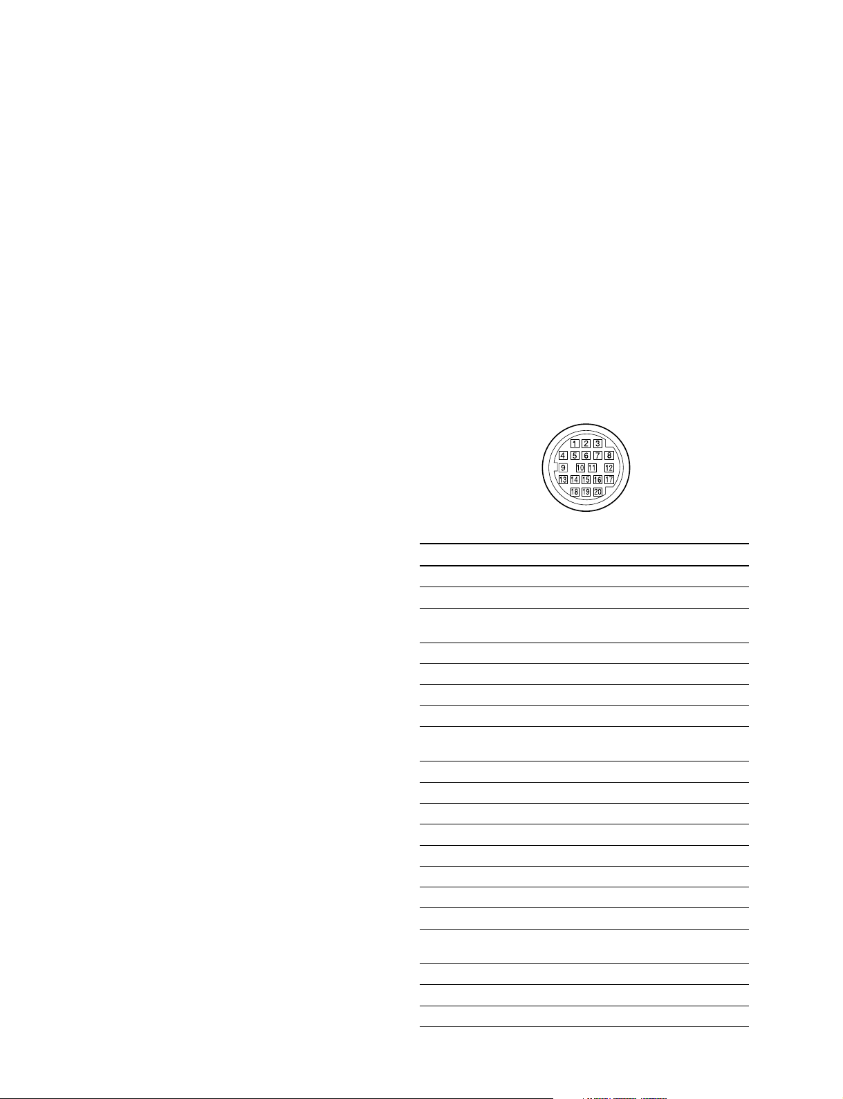
1-5. Input and Output Signals of
Connectors
VF (20P MALE)
(EXTERNAL VIEW)
Pin No. Signal Name I/O Specifications
1 S-DATA IN/OUT TTL level
2 NC No connection
3 POWER IN POWER ON : OPEN
OFF CTL POWER OFF : GND
4 SCK IN TTL level
5 NC No connection
6 NC No connection
7 NC No connection
8 G TALLY IN ON : 5 V
OFF : GND
9 NC No connection
10 NC No connection
11 NC No connection
12 Y VIDEO IN 1.0 V p-p Zo = 75 Z
13 VIDEO GND GND for VIDEO
14 Pb VIDEO IN 0.7 V p-p Zo = 75 Z
15 Pr VIDEO IN 0.7 V p-p Zo = 75 Z
16 NC No connection
17 R TALLY IN ON : 5 V
OFF : GND
18 NC No connection
19 UNREG GND GND for UNREG
20 UNREG IN DC 10.5 V to 17 V
1-2 (E)
HDVF-C30W
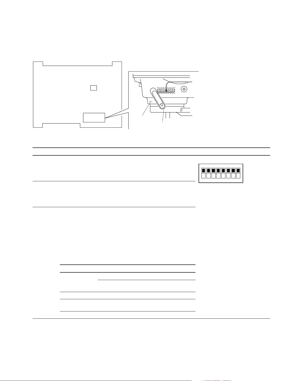
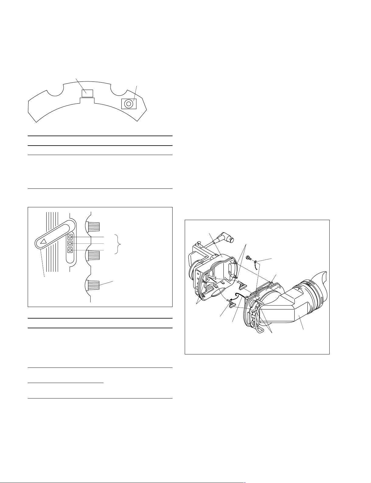
1-6. Functions of On-board Switches and Controls
1-6-1. PR-267 Board
S2
S1
Side panel
Switch cover
S1
S1 Switch
Ref. No. Description Factory setting
S1-1 Selects whether to enable all of the indicators in the upper and lower sections
of the LCD screen, or only the BATT indicator.
OFF : Enable all indicators.
ON : Enable the BATT indicator only.
S1-2 Selects the function of the B&W button on the front panel, B&W display priority
S1-3
or grayscale display priority.
OFF : Priority given to B&W display.
ON : Priority given to grayscale display.
Selects whether the PEAKING variable resistor (RV2/VR-208 board) on the front
panel and the PEAKING control on the side panel should work together with
the MAG button on the front panel or the SEL1/SEL2 switch on the side panel.
OFF : Work together with the SEL1/SEL2 switch.
ON : Work together with the MAG button.
This allows you to use different peaking settings for magnified and normal
display.
The following table shows the relationship between switch S1-3 settings and
the times when the PEAKING control and the PEAKING variable resistor are
enabled and disabled.
12345678
OFF (Upper side)All OFF
ON (Lower side)
HDVF-C30W
S1-3: OFF S1-3: ON
SEL1/SEL2 switch
SEL1 SEL2 ON OFF
PEAKING control*Yes No No Yes
PEAKING adjustment
variable resistor
* : Refer to the Section 1-6-2. (Yes : Enabled, No : Disabled)
*
No Yes Yes No
MAG button
(Magnified display) (Normal display)
(Continued to next page)
1-3 (E)
(Continued from previous page)
Ref. No. Description Factory setting
S1-4 Selects whether the magnified section of the picture is fixed as the center
S1-5 Not used.
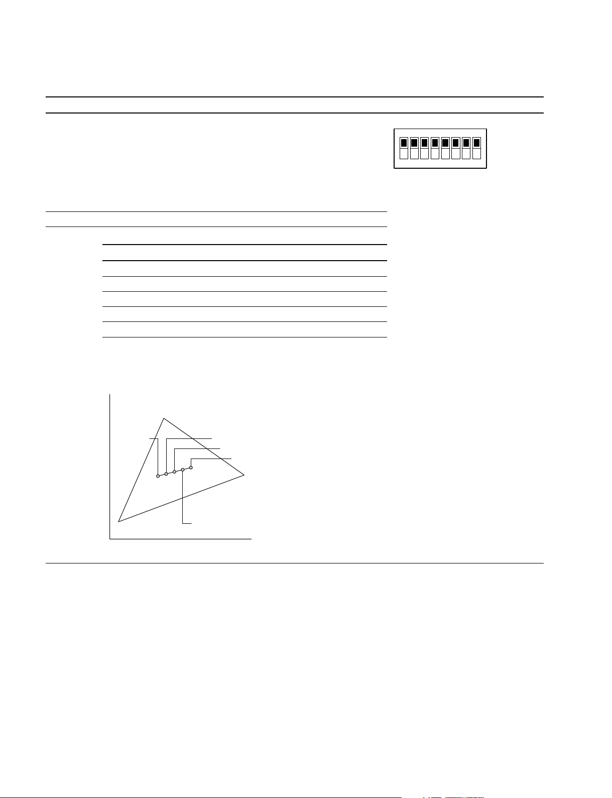
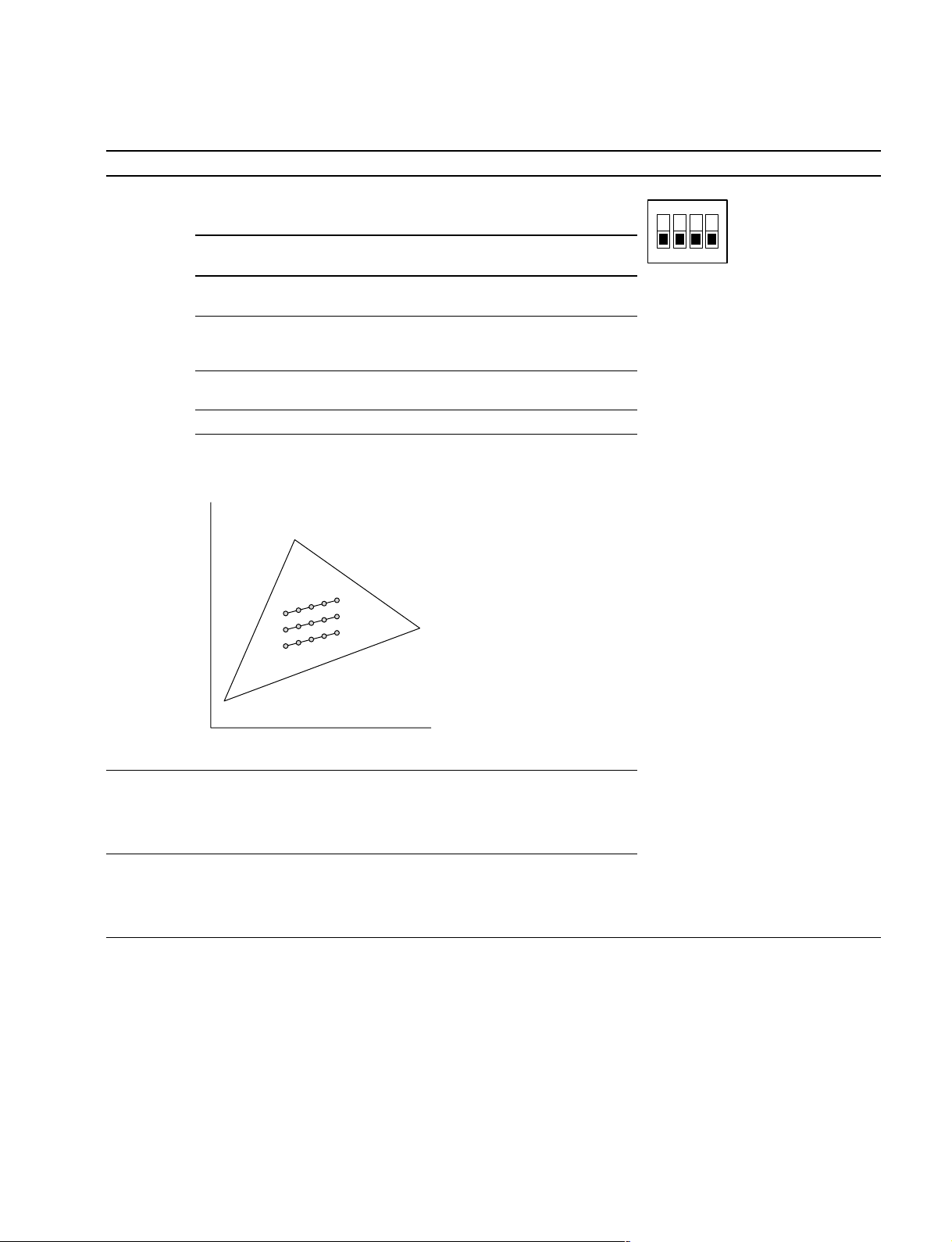
S1-6 to 8 Adjust color temperature.
section or can be selected from the upper left, upper right, lower left, lower right,
and center sections.
(Refer to “Magnifying the Picture” of the Operation Manual for the selection method.)
OFF : Selectable from among the 5 sections.
ON : Fixed as the center section.
In this case, the display automatically returns to normal about 5 seconds
after the MAG button is pressed.
S1-6 S1-7 S1-8 Color temperature
OFF OFF OFF Factory setting (approx. 6500 K)
ON OFF OFF Decreases approx. 500 K (becomes reddish)
OFF ON OFF Increases approx. 500 K (becomes bluish)
ON ON OFF Increases approx. 1000 K (becomes bluish)
OFF OFF ON Increases approx. 1500 K (becomes bluish)
n
Color temperature does not change except by the above switch combinations.
The screen display luminance decreases as a result of color temperature
adjustment.
12345678
OFF (Upper side)All OFF
ON (Lower side)
y
+1500 K
B
Chromaticity diagram
G
+1000 K
+500 K
_500 K
R
[6500 K]
x
1-4 (E)
HDVF-C30W
S2 Switch
1234
All OFF
ON
Ref. No. Description Factory setting
S2-1, 2 Selects whether to enlarge the range of color temperature
adjustment range or not on the y-axis of the chromaticity diagram
with the use of the switch S1-6 to S1-8.
S2-1 S2-2 Chromaticity (y-axis direction)
__
(WB
_Y) (WB
__
OFF OFF Factory default setting (As shown in 1 on the
ON OFF Chromaticity is adjusted toward the minus
OFF ON Chromaticity is adjusted toward the plus (Green)
ON ON _
n
The switches S2-1 and S2-2 should be adjusted in combination
with the switches S1-6 through S1-8.
y
++
+Y)
++
following diagram)
(Magenta) direction. (As shown in 2 on the
following diagram)
direction. (As shown in 3 on the following diagram)
G
3
1
2
B
S2-3 Selects direction of the display scanning forcibly from the right or the left.
OFF : Normal direction (The switch S2 on the VR-208 board is enabled.)
ON : Direction of scanning can be selected forcibly (The switch S2 on the
VR-208 board is disbled.)
S2-4 TEST SAW waveform output switch
ON : Generates the TEST SAW waveform within viewfinder.
Use the TEST SAW signal to check the video signal system using the
EX-909 board.
R
x
HDVF-C30W
1-5 (E)
1-6-2. VR-208 Board
1-7. Replacing the Main Parts
Switch
S2
S1
A side
Ref. No. Description
S1 SEL1/SEL2 selector switch (on side panel)
S2 Selects direction of the display scanning from the
right or the left.
When the viewfinder barrel is installed, this switch is
set to ON so that the scanning in the reverse
direction is obtained.
Variable Resistor
RV4
Adjustment variable
RV6
resistor
RV2
1-7-1. Replacing the LCD Panel
n
Replacement of the LCD panel backlight:
The backlight of the LCD panel has the life of about
40,000 hours as far as the set color temperature remains
constant.
Replace the backlight when luminance of the backlight
decreases to 150 cd/m2 or less as a guideline.
Replacement of the backlight only is not possible. Replace
the entire LCD panel.
1. Loosen the four screws (with drop-safe) securing the
rear chassis and remove the rear chassis.
2. Disconnect the harness from the harness clamp and
disconnect the harness from the connectors (CN1,
CN3) on the PR-267 board.
3. Remove the screw (PS2 x 4) and remove the GND
terminal.
Rear chassis
Screws
(with drop-safe)
PS2 x 4
GND terminal
Adjustment variable
resistor cover
Ref. No. Description
RV2 PEAKING adjustment This adjustment is enabled
RV4 BRIGHTNESS They can be adjusted when
adjustment the SEL1/SEL2 selector
RV6 CONTRAST
adjustment
PEAKING control
by setting of the SEL1/SEL2
selector switch or that of the
MAG button.
For details, refer to Section
1-6-1, Switch S1-3.
switch (on the side panel) is
set to the SEL2 position.
Screws
(with drop-safe)
Harness
Harness
clamp
Viewfinder main unit
PR-267 board
(CN1 and CN3)
Viewfinder
barrel
1-6 (E)
HDVF-C30W
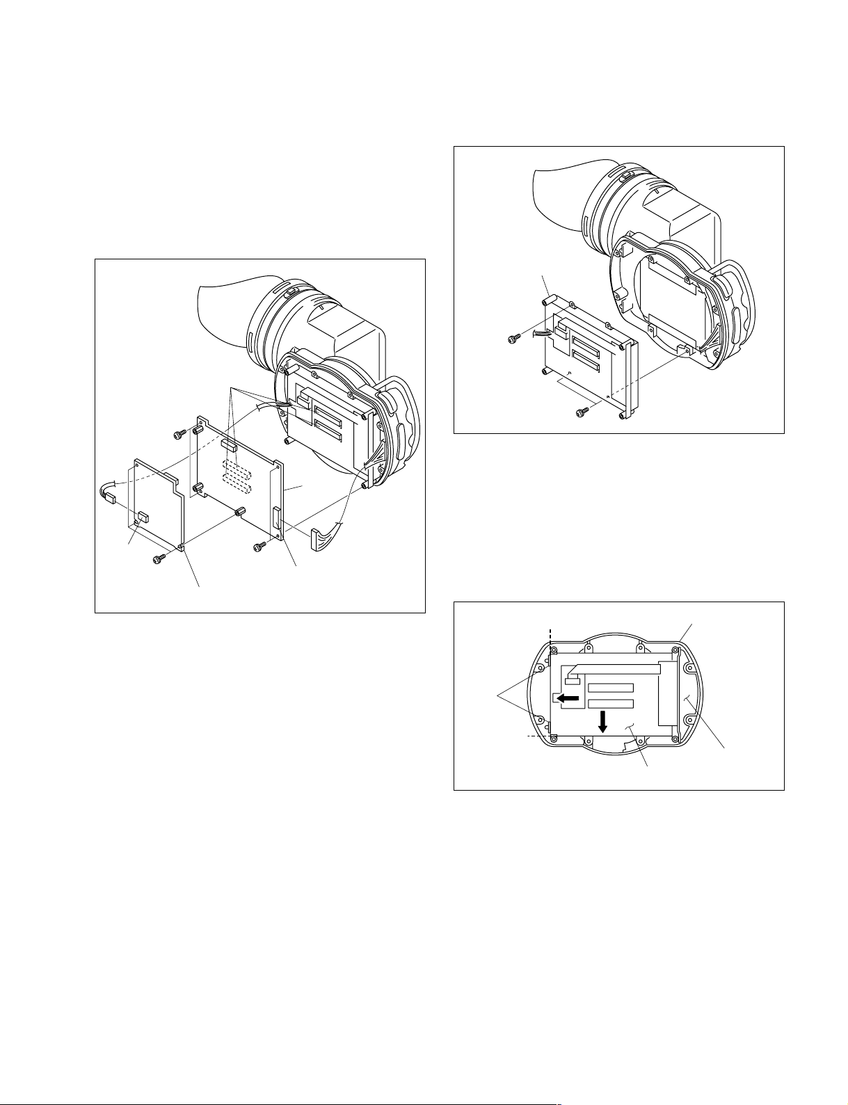
4. Disconnect the harness from the connector (CN2) on
a
VR-280 board
b
Front chassis
LCD panel
Ribs
the RE-208 board.
5. Disconnect the harness from the connector (CN7) on
the PR-267 board.
6. Remove the three screws (M2 x 5) and remove the
RE-208 board from the PR-267 board.
7. Remove the four screws (PS2 x 4) and remove the
board-to-board connector from the PR-267 board.
Board-to-board
connectors
PS2 x 4
PR-267
board
CN2
M2 x 5
PS2 x 4
CN7
RE-208 board
8. Remove the three screws (PS2 x 4) and remove the
LCD panel.
LCD panel
PS2 x 4
PS2 x 4
9. Install the new LCD panel.
Precaution for installation
When installing the new LCD panel, be careful not to
attach dust or fingerprint on the display area of the
LCD panel.
Installation position
Install the LCD panel by pushing it against the sides
“a” and “b” as far as it can go, of the front chassis.
10. Perform the setting of the switches S1 and S2 of the
PR-267 board. (Refer to Section 1-8-1.)
11. Install the removed parts by reversing the steps 1 to 7
of removal.
Precaution for installation
Be sure to insert the connectors to the circuit board
HDVF-C30W
securely for sure connection of the connectors.
1-7 (E)
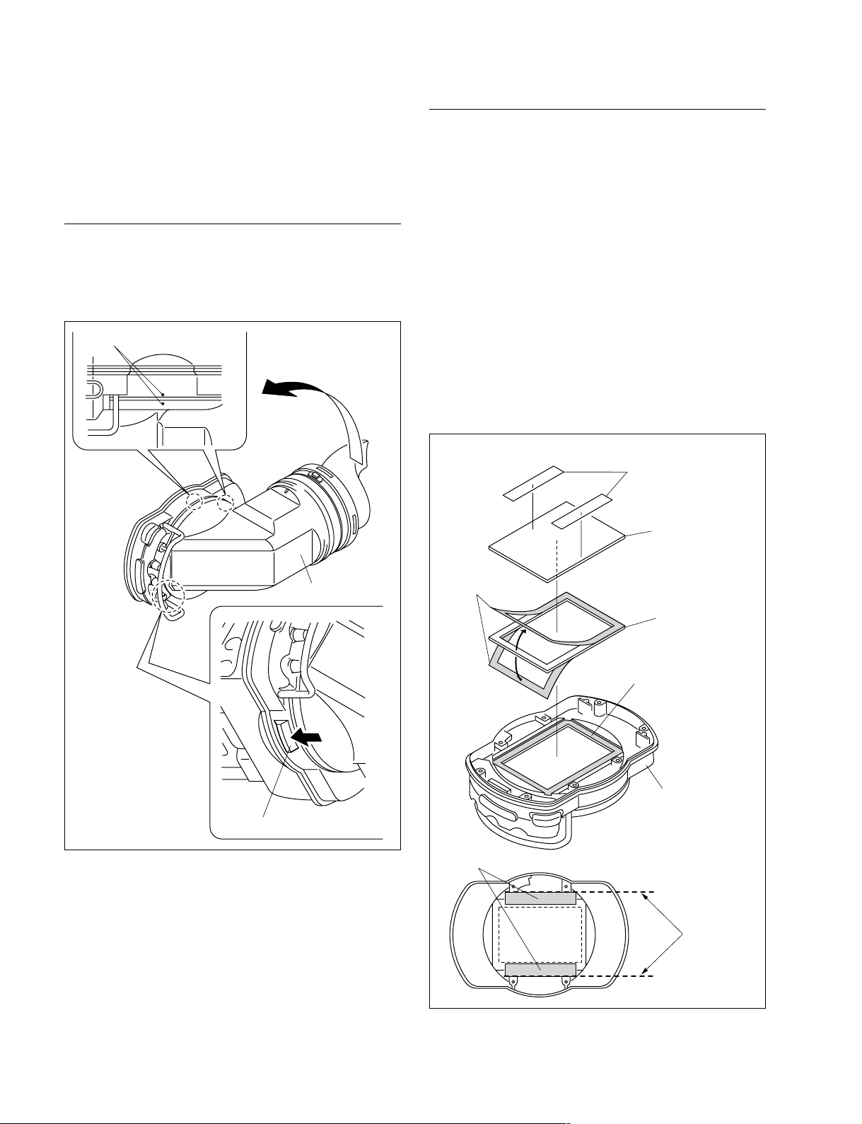
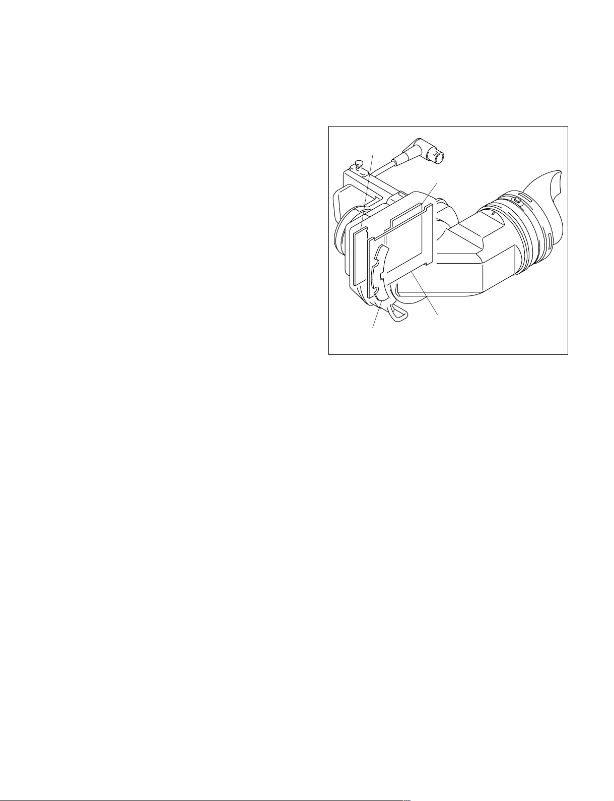
1-7-2. Replacing the Protection Glass
Installation
Parts to be prepared in addition to the protection glass:
. Glass cushion, 1 piece : 3-776-618-xx
. Radiation sheet, 2 pieces : 3-776-623-xx
Removal
1. Push the RELEASE knob in the direction of the arrow
A to release the lock and remove the viewfinder barrel
by rotating it in the direction of the arrow B.
Red marks
Fig. 2
B
6. Peel off the protection sheet from the new glass
cushion and attach the new glass cushion to the
attaching surface.
Precaution for attaching the glass cushion
. Attach the glass cushion so that any portion of the
glass cushion should not protrude from the attaching
surface.
. Attach the glass cushion with care so that any
wrinkle should not be generated.
7.
Peel off the protection sheet form the surface of the glass
cushion attached, and install the new protection glass.
8. Attach the two radiation sheets to the positions as
shown in the illustration.
9.
Install the removed parts by reversing the steps of removal.
Radiation sheets
Protection glass
Viewfinder barrel
A
RELEASE knob
Fig. 1
2. Remove the viewfinder main unit and then remove the
LCD panel.
(Perform steps 1 to 3, 5 and 8 of “1-7-1. Replacing the
LCD Panel.”)
3. Peel off the two radiation sheets.
4. Peel off the protection glass from glass cushion to
remove it.
5. Peel off the glass cushion from the front chassis and
wipe the attaching surface of the glass cushion with
alcohol.
1-8 (E)
Protection
sheets
Glass cushion
Attaching surface
Front chassis
Radiation sheets
Align the
radiation
sheets with
the walls.
Precaution for installation
Align the red marks when installing the viewfinder
barrel. (Fig. 2)
HDVF-C30W
1-7-3. Replacing the Anti-Glare Sheet
The three different types of anti-glare sheet are used as
shown below in this model.
Replace the desired type of anti-glare sheet as necessitated.
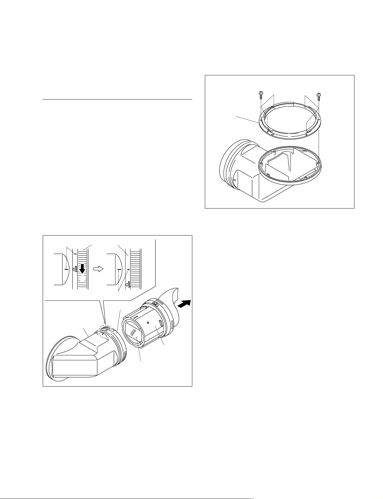
3. Remove the six screws (tapping screw M2 x 5) and
remove the bayonet ring (TUBE) from the viewfinder
barrel.
Tapping screws
M2 x 5
Tapping screws
M2 x 5
Replacing the Anti-Glare Sheet (Ring)
Required part
Anti-glare sheet (Ring) 1 piece : 3-789-426-xx
1. Push the RELEASE knob to release the lock and
remove the viewfinder barrel. (Refer to Section 1-7-2,
step 1.)
2. Rotate the fixed ring fully in the direction of the arrow
A and align the key marks (red lines) of the fixed ring
with that of the viewfinder barrel. Then remove the
viewfinder lens unit.
n
Be extremely careful not to give any scar on the
polarizing filter surface of the viewfinder lens unit
during the removal and installation procedures.
Red lines
Fixed rings
A
Bayonet ring
(TUBE)
Viewfinder barrel
Red lines
Fixed ring
Viewfinder
lens unit
Polarizing filter surface
HDVF-C30W
1-9 (E)
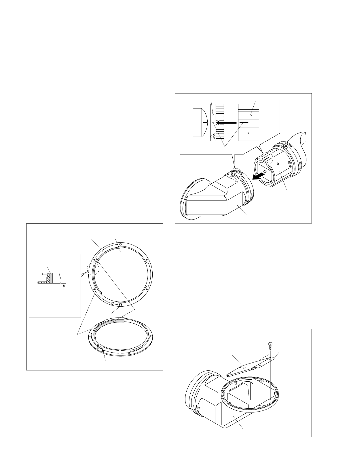
4. Peel off the anti-glare sheet (ring) from the bayonet
ring (TUBE) and wipe the attaching surface with
alcohol.
5. Place the bayonet ring (TUBE) on a flat work bench
with its viewfinder barrel attaching surface facing
downward.
6. Peel off the protection sheet of the new anti-glare sheet
(ring). Align the shorter end-surface of the new antiglare sheet with the flange end surface (side “a”) of the
bayonet ring (TUBE). Attach the new anti-glare sheet
(ring) to the bayonet ring (TUBE) by pressing downward.
Precaution for attaching the anti-glare sheet
(ring)
. Attach the anti-glare sheet (ring) with care so that
the anti-glare sheet (ring) should not float or any
wrinkle should not be generated.
. Attach the anti-glare sheet (ring) so that it should not
protrude exceeding the circumference to which the
viewfinder barrel of the bayonet ring (TUBE) is
going to be installed. (If it protrudes exceeding the
circumference, the anti-glare sheet (ring) becomes
visible on the mirror inside the viewfinder barrel.)
7. Install the removed parts by reversing the steps 1 to 3
of removal.
Precaution for installation
Align the alignment mark (red) of the viewfinder lens
unit with that of the alignment mark (red) of the fixed
ring when installing the viewfinder lens unit, and
insert the viewfinder lens unit.
Fixed ring
Red lines
Viewfinder lens unit
Viewfinder
lens unit
Viewfinder barrel
Anti-glare sheet
(ring)
It should not protrude
exceeding the bottom
end.
Side view
Bayonet rings
(TUBE)
Flange
Side “a”
Slot
Slot
Top view
Anti-glare
sheet (ring)
Replacing the Anti-Glare Sheet (Upper) and (Lower)
Required parts
. Anti-glare sheet (Upper) 1 piece : 3-789-424-xx
. Anti-glare sheet (Lower) 1 piece : 3-789-425-xx
1. Execute steps 1 through 3 of the anti-glare sheet (ring)
replacement procedure.
2. Remove the two screws (tapping screw M2 x 5) and
remove the mirror assembly from the viewfinder barrel.
n
Be extremely careful not to give any scar or stain on
the mirror surface during the removal and installation
procedures.
Tapping screws
M2 x 5
Mirror surface
Mirror
assembly
1-10 (E)
Viewfinder barrel
HDVF-C30W
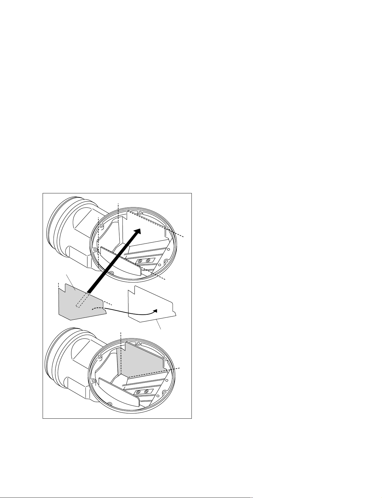
3. Peel off the anti-glare sheet (Upper) and (Lower) from
the viewfinder barrel.
4. Peel off the protection sheet of the new anti-glare sheet
(Upper). Align the new anti-glare sheet with the sides
“a” and “b” of the viewfinder barrel. Attach the new
anti-glare sheet (Upper) to the viewfinder barrel.
Precaution for attaching the anti-glare sheet
(Upper)
. Fold the sides “e” and “f” of the sheet so that they fit
to the shape of the barrel and then attach them.
. Attach the anti-glare sheet (Upper) including the
sides “e” and “f” with care so that the anti-glare
sheet (Upper) should not float or should not create
any wrinkle.
5. Similarly, align the anti-glare sheet (Lower) with the
sides “c” and “f” and attach it to the viewfinder barrel.
a
c
1-8. Setup after Replacement of the
Main Parts and Board
1-8-1. When the LCD Panel is Replaced
Return the settings of the switches S1 (C-2) and S2 (B-2)
on the PR-267 board to the default setting when shipped
from the factory.
S1-6 to S1-8 : OFF (Preset the chromaticity setting.)
S2-1 to S2-4 : All OFF
1-8-2. When the PR-267 Board is Replaced
Set the switches S1 (C2) and S2 (B-2) settings to the
original setting of the board.
Anti-glare sheet
(Upper)
a
b
d
b
e
Protection sheet
f
6. Install the removed parts by reversing the steps 1 and 2
of removal.
HDVF-C30W
1-11 (E)
1-9. Fixtures and Measuring Instruments
1-9-1. List of Fixtures and Measuring
Instruments
Name of the fixture/ Sony part Application
measuring instrument
EX-909 board A-8346-442-A Used to check the
RE-208 EX unit A-8346-433-A Used to check the
Connecting cable 1-827-086-21 . Used to check the
Pattern box PTB-500 J-6029-140-B Used to adjust
PLD download tool J-7120-140-A Used to rewrite the
Luminance meter
* : Use of the Minolta Model LS-100 Luminance Meter is recommended.
number
PR-267 board
RE-208 board
. Used to rewrite the
brightness
PLD data
*
_ Used to adjust the
brightness
PR-267/RE-208
board
PLD data
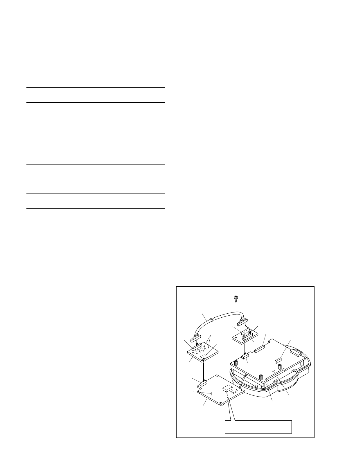
1-9-2. How to Extend the RE-208 Board
1.
Remove the viewfinder barrel.
(Refer to Section 1-7-2, setp 1.)
2. Perform steps 1 to 3 of “1-7-1. Replacing the LCD
Panel.”
3. Remove the RE-208 board.
(Refer to Section 1-7-2, step 6.)
n
Do not disconnect the harness from the connector CN2
on the RE-208 board.
4. Connect the EX-907 board to the CN2 connector on
the PR-267 board. Because this connector is easy to
be dropped off, secure the EX-907 board with the
screw that was removed in the step 3.
5. Connect the EX-908 board to the CN1 connector on
the RE-208 board.
6. Connect the connecting harness to the CN2 on the EX907 and the EX-908 board, respectively.
c
Side A of the RE-208 board has high-voltage area of
DC/AC inverter transformer.
While turning on the electricity, perform the checks
with extreme care so that you might not get the electric
shock. (Refer to Section 1-12.)
7. Connect the connecting cable to the CN1 connector on
the PR-267 board and the camera.
n
Attach the insulating tape to the GND terminal of the
connecting cable.
PS2 x 4
Connecting harness
EX-907
board
CN1
CN3
CN2
CN2
PR-267 board
LCD panel
CN2
EX-908
board
CN1
B side
CN1
TP terminals
CN1
RE-208
board
1-12 (E)
DC/AC inverter transformer:
Caution! High Voltage (A side)
HDVF-C30W
 Loading...