

Page 1
HD ELECTRONIC VIEWFINDER
HDVF-700A
電気製品は、安全のための注意事項を守らないと、火災
や人身事故になることがあり、危険です。
このオペレーションマニュアルには、事故を防ぐための重要な注意事項と製
品の取り扱いかたを示してあります。このオペレーションマニュアルをよく
お読みのうえ、製品を安全にお使いください。お読みになったあとは、いつ
でも見られるところに必ず保管してください。
OPERATION MANUAL
[Japanese/English]
1st Edition (Revised 1)
Page 2

目次
警告 ................................................................................................................
注意 ................................................................................................................
概要 .....................................................................................................................
各部の名称と働き ...............................................................................................
カメラに取り付ける ............................................................................................
位置を調節する ─チルティング操作 .................................................................
画面を調整する ...................................................................................................
アクセサリーを取り付ける ..............................................................................
仕様 ..................................................................................................................
2(J)
2(J)
3(J)
4(J)
6(J)
8(J)
9(J)
10(J)
12(J)
日
本
語
1(J)
Page 3
下記の注意を守らないと、
火災や感電により死亡や大けがにつながることがあります。
分解しない、改造しない
分解したり、改造したりすると、感電の原因となります。
ビューファインダー内部の調整や点検を行う必要がある場合は、必ずソニー
のサービス担当者にご依頼ください。
内部に水や異物を入れない
水や異物が入ると火災の原因となります。
万一、水や異物が入ったときは、すぐにカメラの電源を切り、接続コードを
抜いて、ソニーのサービス担当者または営業担当者にご相談ください。
下記の注意を守らないと、
けがをしたり周辺の物品に損害を与えることがあります。
油煙、湯気、湿気、ほこりの多い場所では設置•使用しない
上記のような場所で設置・使用すると、火災や感電の原因となります。
ビューファインダーの取り付けは確実に行う
ビューファインダーは確実に固定してください。正しく取り付けられていな
いと、落下してけがの原因となることがあります。
2(J)
Page 4
安全のために
電気製品はまちがった使い方をすると、火災や感電などにより死亡や大けが
など人身事故につながることがあり、危険です。
事故を防ぐために次のことを必ずお守りください。
安全のための注意事項を守る
2(J)ページの注意事項をよくお読みください。
定期点検を実施する
長期間安全に使用していただくために、定期点検を実施することをおすすめ
します。点検の内容や費用については、ソニーのサービス担当者または営業
担当者にご相談ください。
故障したら使用を中止する
ソニーのサービス担当者または営業担当者にご連絡ください。
万一、異常が起きたら
1 カメラの電源を切る。
異常な音、
•
におい、煙
が出たら
落下させた
•
ら
,
2 接続コードを抜く。
3 ソニーのサービス担当者または営業担当者に修
理を依頼する。
警告・注意表示の意味
このオペレーションマニュアル
および製品では、次のような表
示をしています。表示の内容を
よく理解してから本文をお読み
ください。
この表示の注意事項を守らない
と、火災や感電などにより死亡
や大けがなど人身事故につなが
ることがあります。
この表示の注意事項を守らない
と、けがをしたり周辺の物品に
損害を与えることがあります。
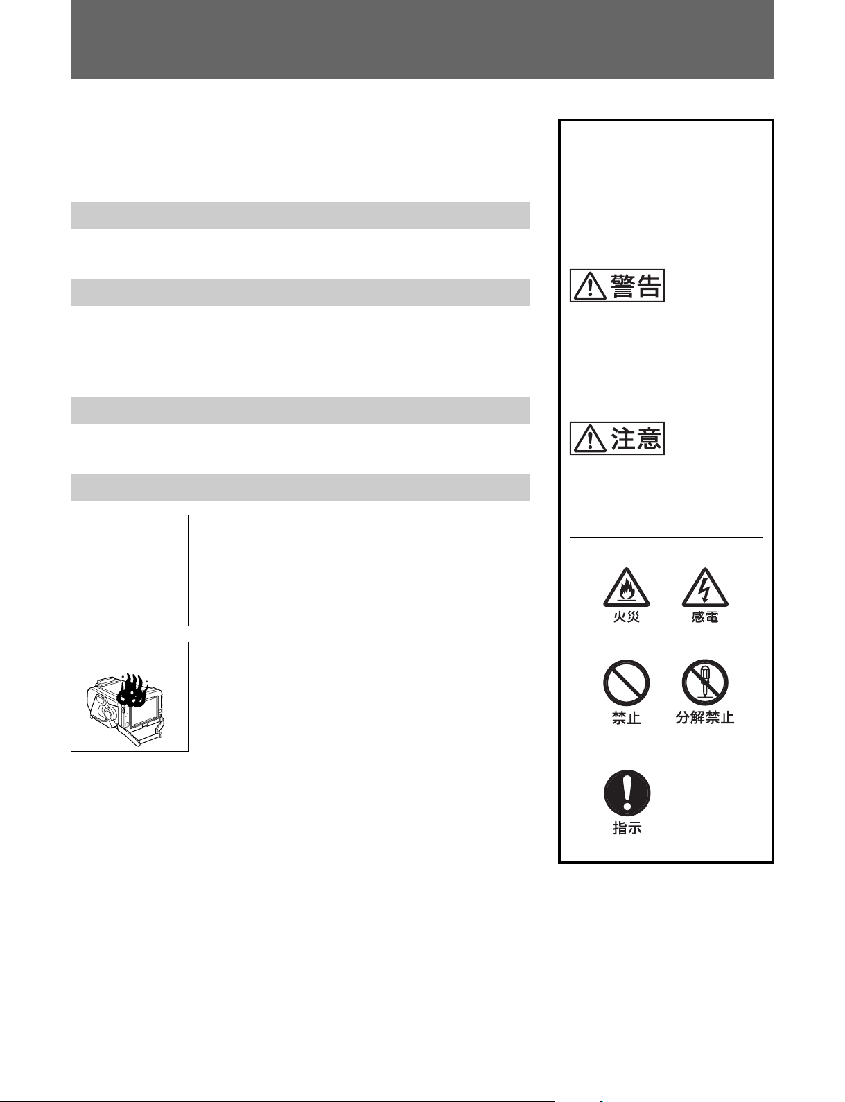
注意を促す記号
炎が出たら
すぐにカメラの電源を切り、消火する。
,
行為を禁止する記号
行為を指示する記号
Page 5

概要
HDエレクトロニックビ ューファインダーHDVF-700Aは、ソニーハイ
ビジョンカラーカメラ用 の 7 インチ白黒ビューファインダーです。
本機には以下のような特長があります。
マルチスキャン
カメラからの制 御 信号により、これまでの 60iに加えて、24PsF や
50iなどの各種フォーマットに 対 応します。
表示が可能
16:9
カメラコントロールユニットな どの外部機器からの操作により、画面
を16:9または4:3表示に切り換えられます。
高解像度
高性能ブラウン管を採用し、水平解像度800本以上の高解像度を
実現しています。
安定した画像
タリーランプ
タリー信 号によって点灯する2系統(レッドおよび グリーン) のタリーラ
ンプを備えています。
優れた操作性
高さを 3 段 階 に設定でき、チルティング角度は、最大上方向に60°
下方向に50°まで変えることが できます。
防滴構造
多少の雨にも耐えられる防滴構造により、戸外での撮影にも適して
います。
スタジオ用屋内フードおよびOB用屋外フードを
取り付け可能
堅牢で操作性のよいスタジオ用屋内フード(付属)と、遮光性に優
れているOB用屋外フード(別売り)を 取り付けることが できます 。
高圧安定回路により、画面の明るさに関係なく、ひずみの少ない
安定した画像が得られます。
連続可変ピーキング補正
連続可変ピーキング補正回路により、シャープな画像が 得られ 、カ
メラ のピント合わせが容易です。
省エネルギー設計
入力電圧の許容範囲が広く(10.5 〜 17V)、しかも低消費電力
(33W)です。
3(J)
Page 6
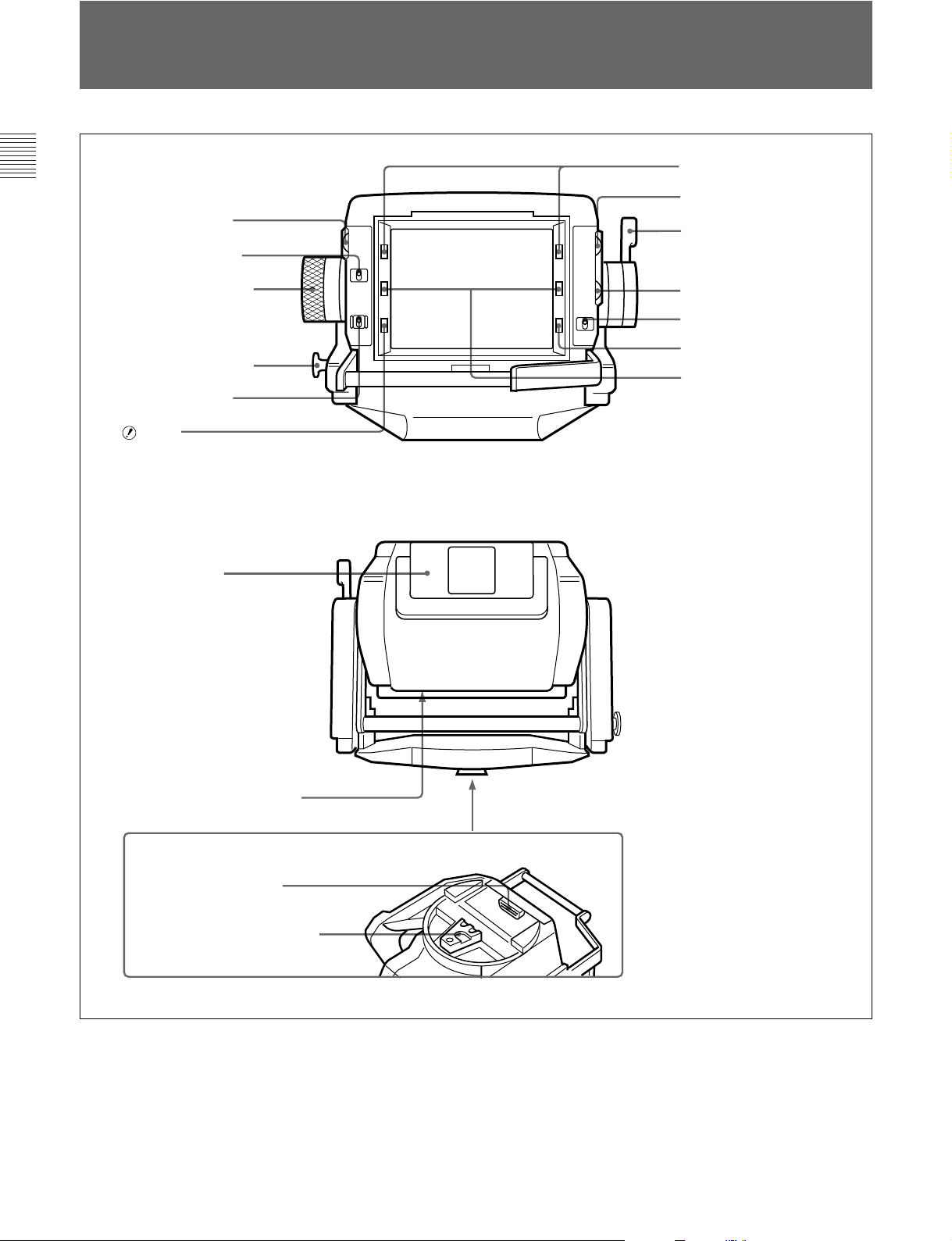
各部の名称と働き
7 グリーンタリーランプ
1
PEAKING
2
PEAKING
3 フリクション調節ノブ
リフトロック解除ノブ
4
5
POWER
6 ランプ
qf 外部タリーランプ
つまみ
スイッチ
スイッチ
前面
後面
8
BRIGHT
ロックレバー
9
0
CONTRAST
qa
TALLY ON/OFF
qs
BATT
qd レッドタリーランプ
つまみ
つまみ
ランプ
スイッチ
qg 外部タリー光量調節ボリューム
qh カメラ端子
qj マウントウェッジ
4(J)
底面
Page 7
1
PEAKING(
PEAKINGスイッチ 2がONのとき、画像の輪郭を補正できます。
右に回すと補正量が多くなります。調整可能範囲は0〜18dB で
す。
2
PEAKING(
PEAKINGつまみ1 の機能をコントロールします。
:ピーキングを補正できる。
ON
:PEAKINGつまみ1が働かなくなり、補正量が0になる。
OFF
3
フリクション調節ノブ
チルティング操作のフリクションを 希望の度合いに調節します。
4 リフトロック解除ノブ
このノブを引っ張っりながら、本機の高さを調節します。高さを、標
準位置(低位置)、最高位置または中間位置に調節してノブを離す
と、本 機はその高さに固定されます。
ピーキング調整)つまみ
ピーキング調整)スイッチ
1)
0
CONTRAST(
画面のコントラストを調節します。
qa
TALLY ON/OFF(
外部タリーランプ qfをコントロールします。
:タリーランプ が機能する。
ON
:タリーランプ が機能しない(レッドタリー 信 号 が カメラに 供
OFF
給され ても、点灯しません)。
qs
BATT (
カメラに 接 続した バッテリーの電圧が下がると点滅します。バッテ
リー が使用できなくなると点灯します。
動作中断を防ぐため、バッテリーが点滅を開始した時点で、すば
やくバッテリーを交換してください 。
◆点滅を開始する電圧を、カメラ側で設定することができます。詳しくは、
使用しているカメラのマニュアルをご 覧ください 。
コントラスト調整)つまみ
タリーオン/オフ)スイッチ
バッテリー)ランプ
1)
5
POWER(電源)
カメラから本機への電源供給をON/OFFします。
6
(注意)
カメラがある特定 の 状 態になったとき点 灯します。どの状態で点灯
させるかは、カメラで設定できます。
◆ランプが点灯する条 件を設 定/ 確認する方法については、使用して
いるカメラのマ ニュアルをご覧ください。
7 グリーンタリーランプ
カメラにグリーンタリー 信 号 が供給されると点灯(緑)します。
8
BRIGHT(
画面の明るさ(輝度)を調節します。
9
ロックレバー
本機を希望の角度に固定するレバーです。レバーをカメラのレンズ
側に倒すと固定され、手前に倒すと、フリクション調節ノブ 3で調
整されたフリクションで角度を調節できます。
スイッチ
ランプ
2)
明るさ調整)つまみ
1)
qd レッドタリーランプ
カメラにレッドタリー 信 号 が供給されると点灯(赤)します。
qf
外部タリーランプ
カメラにレッドタリー 信 号 が供給されると点灯(赤)します。0から9ま
でのナンバープレート( 付属)を取り付けて、カメラの番 号を表示で
きます。
外部タリー光量調節ボリューム
qg
調整用ドライバーなどを差し込んで光量を調整できます。右方向に
回すと明るくなり、左方向に回すと暗くなります 。
カメラ端子
qh
カメラのビューファインダー端子と接続します。
qj
マウントウェッジ
本機をカメラに取り付けるとき、カメラ上面のV字型溝にはめます。
(D-sub 25ピン)
2)
..............................................................................................................................................................................................................................................................
1) これらのつまみによる調整はカメラ映 像出力には影 響しません。
2) このランプの明るさは、本機内部のつまみで調整できます。操作につい
ては、ソニーのサービス担当者にご依頼ください。
5(J)
Page 8
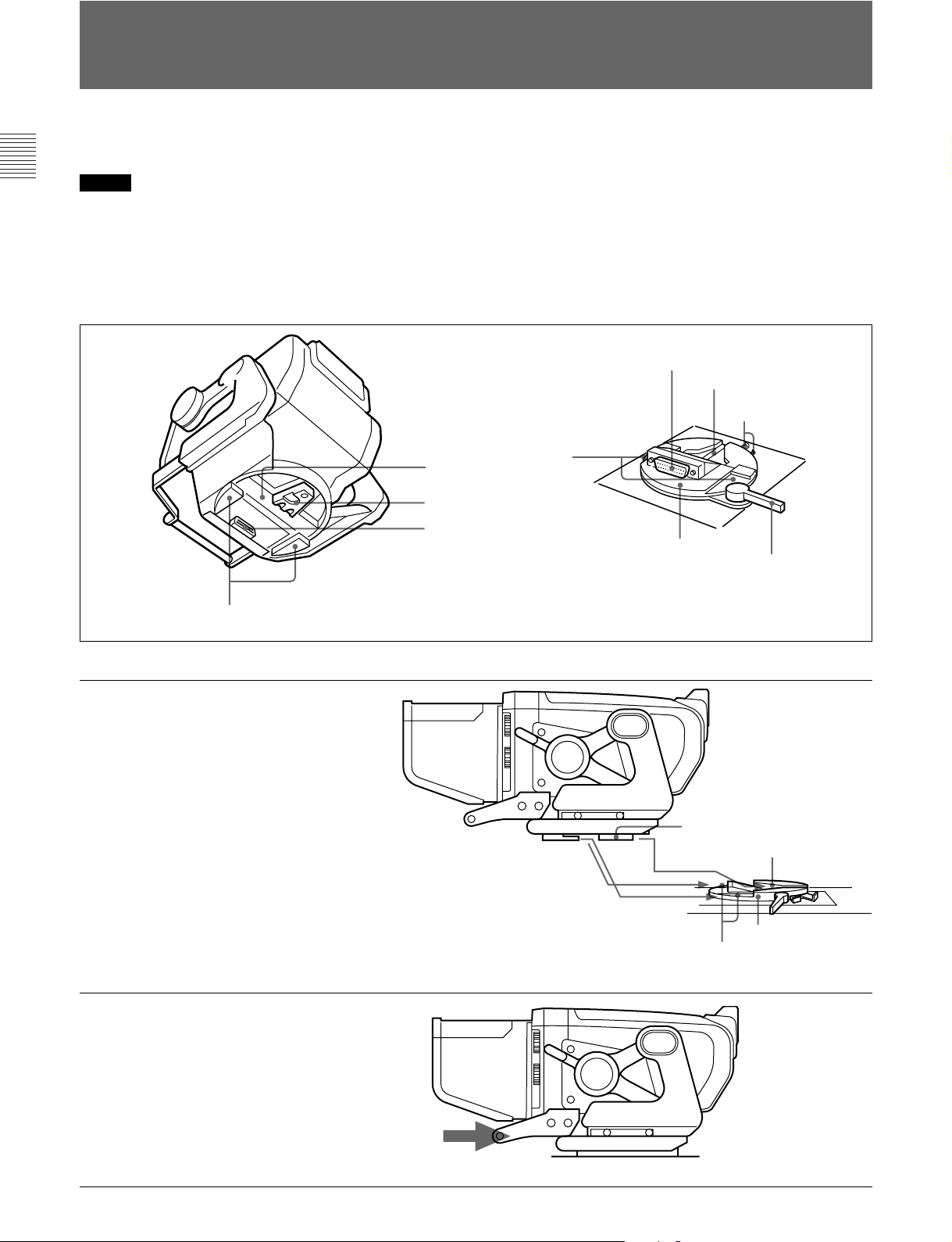
カメラに取り付ける
本機をカメラ上面のパンベース受け台(下図)に取り付けます。
ご注意
• 本機をカメラに取り付け/ 取り外しするときは 、かならず本機を標
準位置(最低位置)にロックしてください。
• ビューファインダーを取り付ける前に、カメラの パンベース受け台
のVF端子が、カメラのコントロールパネルを基 準にして時計回り
に90゜の向きになっていることを確認してください。
パンベース
マウントウェッジ
カメラ端子
本機底面
突起部
◆本機の位置を変える方法については、「位置を調節する―チルティング
操作」(8(J)ページ)の手順をご覧ください。
端子
VF
字型溝
V
ロック解除つまみ
溝
パンベース受け台
パンニングロックレバー
ビューファインダー取り付け部
(カメラ上面)
1 マウントウェッジを V 字型溝に、突起部
をパンベース受け台の左右の溝に合
わせて、本機をパンベース受け台に
乗せる。
2 本機の取っ手を持って、本機を押す。
カメラ端子が、VF端子に接続されま
す。
ビューファインダー取り付け機構
突起部
マウントウェッジ
字型溝
V
パンベース受け台
溝
カメラのコントロールパネル側
6(J)
カメラのコントロールパネル側
Page 9
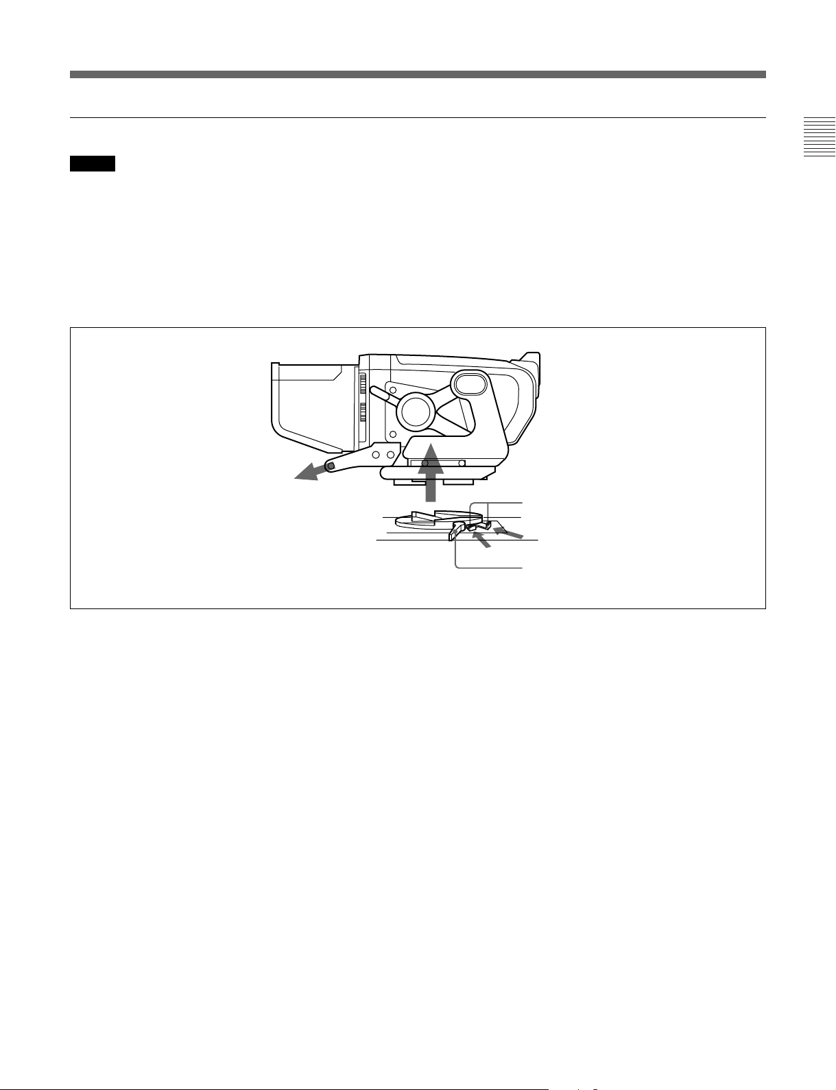
取り外すときは
ご注意
ビューファインダーを取り外す前に、カメラのパンニングロックレ
バーを解除し、ビューファインダーをカメラのコントロールパネルを 基
準にして時計回りに 90゜回転させてください。この位 置 でないと、
ビューファインダーを 取り外すことができません。
ロック 解除つまみを押し込んだまま、本機の取っ手を持って本機を
引き上げ、取り外します。
ロック解除つまみ
カメラのコントロールパネル側
パンニングロックレバー
7(J)
Page 10

位置を調節する ―チルティング操作
ご注意
本機をカメラに取り付け たままカメラを移動するときは、本機を標準
位置(最低位置)まで引き下げ、ロックレ バ ーをレン ズ 側 に 倒し てく
ださい。また、リフトロック解 除ノブ が 、標準位置の溝にはまってい
ることを 確 認し てください。
1 ロックレバ ーを 手 前に倒す。
ロックレバー
2 リフトロック解 除ノブを引っぱりながら、本機の取っ手を持って、
本機を最高位置または中間位置まで引き上げます。
3 フリクション調節ノブを回し て、フリクションを 調 節 する。
フリクション調節ノブ
4 チルティング角度を調節する。
チルティング角度を調節した後は、ロックレ バ ーをカ メラのレン
ズ側に倒してロックします。
°
25
60
°
ご注意
このとき、リフトロック 解 除ノブの みを持って引き上げると、高さ設定
が正常にロックされないときがありますので、必ず取っ手を持って
引き上げ てください。
中間位置
25
°
最高位置
50
°
8(J)
Page 11

画面を調整する
4
3
1 BRIGHT つまみを回して、画面の明るさを調節する。
明るくす るには、時計方向に回します。
ご注意
BRIGHTつまみが反時計方向いっぱいになっていると、画像
が出ないことがありますのでご注意ください 。
2 CONTRASTつまみを回して、画面のコントラストを調節する。
1
2
3 PEAKING 切り換えスイッチを O N にする。
4 PEAKING つまみを回して、ピーキングを補正する。
輪郭をはっきりとさせるには、時計方向に回します。
9(J)
Page 12

アクセサリーを取り付ける
フードを取り付けるには
スタジ オ 用屋内フード(付属)の取り付けかたを説明します。
OB用屋外フードVFH-770(別売り)の取り付けかたも同じです。
1 溝に引っかけて、取り付ける。
2 ネジを回して固定する。
溝
フードは上方向に30°向きを変えることが できます。
屋内フード
ネジ
10(J)
Page 13

用屋外フード(別売り
OB
屋外フードが 動きにくいときや、逆に所定の位置に留まりにくいとき
は、コインネジで調 節します。右に回すと動きが重くなり、左へ回す
と軽くなります。
)
コインネジ
ナンバープレートを取り付けるには
ナンバープレート( 付 属 ) の 左 右 のつめを外部タリーランプ の溝に差
し込みます。
ナンバープレート
1
外部タリーランプ
11(J)
Page 14

仕様
一般
電源 DC10.5〜17.0V(カメラから供給)
消費電力 33W
使用温度 −20℃〜+ 45℃
質量 5.0kg(フード含まず)
外形寸法(単位:mm)
265
178
362
300
CRT
90 度偏向7型モノクローム
寸法 160×131mm(幅 /高さ)
有効画面 120×90mm(水平 /垂直、アスペクト比
4:3)
1080/ 60i/ 33.75kHz/ 60Hz
1035/ 59.94i/ 33.72kHz/ 59.94Hz
1035/ 60i/ 33.75kHz/ 60Hz
ビデオ入力 1.0Vp-p±6dB、75Ω終端
ビデオ入力 1.0Vp-p±6dB(SMPTE240M)、75Ω
終端
直流再生 バックポーチタイプ
バックポーチレベ ル:ピーク値 2%以下、
(APL変動10%〜 90%に対する黒
レベル変動)
周波数特性 0.1〜23MHz(± 2dB)
23〜27MHz(±3dB)
ピーキング 0dB 〜18dB(17MHz)
同期 引き込み範囲:水平±500Hz 以上、垂直
−10Hz以上
水平保持範囲:± 500Hz 以上
接続端子
カメラ端 子 D-sub25ピン
偏向および高圧系
輝度 500cd/m
解像度 中心部:800本
周辺部:600本
画面ひずみ 2.0% 以下
高圧レギュレーション
±2%以内
高圧電圧 12.5kV(標準)
2
入力電圧および信号特性
対応フォーマット
有効走査線数/フォーマット/ 水平走査線周波数 /
垂直走査線周波数
1080/ 23.98PsF/ 26.97kHz/ 47.95Hz
1080/ 24PsF/ 27kHz/ 48Hz
1080/ 25PsF/ 28.13kHz/ 50Hz
1080/ 29.97PsF/ 33.72kHz/ 59.94Hz
1080/ 30PsF/ 33.75kHz/ 60Hz
1080/ 50i/ 28.13kHz/ 50Hz
1080/ 59.94i/ 33.72kHz/ 59.94Hz
付属品
屋内フード(1)
ナンバ ープレート(1)
ヒューズ(1)
オペレーションマニュアル(1)
別売り品
屋外フードVFH-770
関連製品
HDカラービデオカメラHDC-900/950
ラージレンズ アダ プター CA-905L
ビューファインダーサドル BKP-9057
本機の仕様および外観は、改良のため予告なく変更することがあ
ります が 、ご了承ください。
12(J)
Page 15

Page 16

WARNING
To prevent fire or shock hazard, do not
expose the unit to rain or moisture.
Dangerously high voltages are present
inside the set. Do not open the cabinet.
Refer servicing to qualified personnel
only.
Pour les clients européens
Ce produit portant la marque CE est conforme à la Directive
sur la compatibilité électromagnétique (EMC) (89/336/CEE)
émise par la Commission de la Communauté européenne.
La conformité à cette directive implique la conformité aux
normes européennes suivantes:
• EN55103-1: Interférences électromagnétiques (émission)
• EN55103-2: Sensibilité électromagnétique (immunité)
Ce produit est prévu pour être utilisé dans les
environnements électromagnétiques suivants:
E1 (résidentiel), E2 (commercial et industrie légère), E3
(urbain extérieur) et E4 (environnement EMC contrôlé ex.
studio de télévision).
For the customers in the USA
This equipment has been tested and found to comply with
the limits for a Class A digital device, pursuant to Part 15 of
the FCC Rules. These limits are designed to provide
reasonable protection against harmful interference when the
equipment is operated in a commercial environment. This
equipment generates, uses, and can radiate radio frequency
energy and, if not installed and used in accordance with the
instruction manual, may cause harmful interference to radio
communications. Operation of this equipment in a residential
area is likely to cause harmful interference in which case the
user will be required to correct the interference at his own
expense.
You are cautioned that any changes or modifications not
expressly approved in this manual could void your authority
to operate this equipment.
The shielded interface cable recommended in this manual
must be used with this equipment in order to comply with the
limits for a digital device pursuant to Subpart B of Part 15 of
FCC Rules.
For the customers in Europe
This product with the CE marking complies with the EMC
Directive (89/336/EEC) issued by the Commission of the
European Community.
Compliance with this directive implies conformity to the
following European standards:
• EN55103-1: Electromagnetic Interference (Emission)
• EN55103-2: Electromagnetic Susceptibility (Immunity)
This product is intended for use in the following
Electromagnetic Environment(s):
E1 (residential), E2 (commercial and light industrial), E3
(urban outdoors) and E4 (controlled EMC environment, ex.
TV studio).
Für Kunden in Europa
Dieses Produkt besitzt die CE-Kennzeichnung und erfüllt die
EMV-Richtlinie (89/336/EWG) der EG-Kommission.
Angewandte Normen:
• EN55103-1: Elektromagnetische Verträglichkeit
(Störaussendung)
• EN55103-2: Elektromagnetische Verträglichkeit
(Störfestigkeit),
für die folgenden elektromagnetischen Umgebungen: E1
(Wohnbereich), E2 (kommerzieller und in beschränktem
Maße industrieller Bereich), E3 (Stadtbereich im Freien) und
E4 (kontrollierter EMV-Bereich, z.B. Fernsehstudio)
Page 17

Table of Contents
English
Overview ............................................................................................... 2(E)
Location and Function of Parts .......................................................... 3(E)
Attaching to the Camera ..................................................................... 6(E)
Adjusting the Position — Tilting........................................................ 8(E)
Adjusting the Screen ........................................................................... 9(E)
Attaching Accessories ........................................................................ 10(E)
Specifications...................................................................................... 12(E)
1(E)
Page 18

Overview
The HDVF-700A HD Electronic Viewfinder is a 7type monochrome viewfinder for use with a Sony
high-definition color camera.
This viewfinder has the following features:
Multiscan
In addition to the 60i format, formats such as 24PsF
and 50i are supported for control signals from the
camera.
16:9 display capability
When operated from an external device such as a
camera control unit, the screen can be switched
between 16:9 and 4:3 display modes.
High resolution
The viewfinder uses a high-resolution cathode-ray
tube, providing 800 or more lines of horizontal
resolution.
Tally lamps
The viewfinder has red and green tally lamps which
light in response to tally signals.
Superior usability
The viewfinder height may be set to one of three
positions, and it may be tilted up to 60º upwards or 50º
downwards.
Drip-proof construction
The drip-proof design is able to withstand light rain,
making the viewfinder well suited to outdoor use.
Studio monitor hood, outdoor hood
The viewfinder may be fitted with a strong, easy-touse studio hood (supplied), or an outdoor broadcasting
(OB) hood with excellent shading ability (option).
Stable picture
A high-voltage regulation circuit provides a stable
image with a minimum of distortion, regardless of
screen brightness.
Continuously variable peaking
A continuously variable peaking circuit provides a
sharp image, making it easy to focus the camera.
Energy-saving design
The viewfinder will accept a wide range of power
supply voltage (from 10.5 to 17 volts) with low power
consumption (33 watts).
2(E)
Page 19

Location and Function of Parts
1 PEAKING control
2 PEAKING switch
7 Green tally lamps
8 BRIGHT control
9 Lock lever
3 Friction adjustment
knob
4 Lift-lock release knob
5 POWER switch
6 indicator
qf External tally lamp
0 CONTRAST control
qa TALLY ON/OFF switch
qs BATT indicator
qd Red tally lamps
Front
Rear
qg External tally dimmer control
qh CAMERA connector
qj Mounting wedge
Bottom
3(E)
Page 20

Location and Function of Parts
1 PEAKING control
1)
When the PEAKING switch 2 is set to ON, this
control can be used to sharpen the edges in the picture.
Turning the control clockwise will increase the
sharpness. The peaking can be adjusted from 0 to 18
dB.
2 PEAKING switch
When this switch is set to ON, peaking can be adjusted
using the PEAKING control
set to OFF, the PEAKING control
1. When the switch is
1 is disabled, and
the peaking value will be 0 dB.
3 Friction adjustment knob
Used to adjust the amount of friction in the tilting
mechanism.
4 Lift-lock release knob
The viewfinder height can be adjusted while pulling
this knob. By releasing the knob after adjusting the
height to the standard (low), middle position, or top
position, the viewfinder will remain fixed at that
height.
5 POWER switch
Turns the power supply from the camera to the
viewfinder on and off.
(attention) indicator
6
This indicator lights when the camera detects certain
conditions. The particular conditions which cause the
indicator to light up are set by the camera.
For information on how to set up and verify the conditions
under which the indicator will light, refer to the manual
for the camera being used.
7 Green tally lamps
2)
Light up when the camera receives a green tally signal.
8 BRIGHT (brightness) control
1)
Used to adjust the picture brightness.
9 Lock lever
This lever is used to lock the viewfinder into a desired
angle. The angle is locked when the lever is pushed
towards the camera lens. When the lever is pulled
toward the back of the camera, the angle can be
adjusted. The tilt mechanism will resist movement
with the amount of friction set by the friction
adjustment knob
0 CONTRAST control
3.
1)
Used to adjust the picture contrast.
qa TALLY ON/OFF switch
Controls the external tally lamp qf. When set to ON,
the external tally lamp will operate. When set to OFF,
the lamp will not operate (will not light in response to
a tally signal).
qs BATT (battery) indicator
This indicator blinks when the voltage output of the
camera battery drops. When the battery reaches a
point that it may no longer be used, the indicator will
light up.
To prevent camera shutdown due to the battery
running down, change the battery as soon as possible
after this indicator begins blinking.
The threshold battery voltage value to make this indicator
begin blinking is set by the camera. For details, refer to the
manual for the camera.
qd Red tally lamps
2)
Light up when the camera receives a red tally signal.
qf External tally lamp
Lights up red in response to a red tally signal. Can be
used to display the camera number by attaching one of
the supplied number plates (0 through 9).
qg External tally dimmer control
Used to adjust the brightness of the external tally lamp.
Use a screwdriver to turn the control clockwise to
increase the brightness, or counterclockwise to dim the
lamp.
........................................................................................................................................................................................
1) These controls have no effect on the camera’s video
output signals.
2) The brightness of these lamps can be adjusted using
controls inside the viewfinder body. For more
information, contact qualified Sony service personnel.
4(E)
Page 21

qh CAMERA connector (D-sub 25-pin)
Used to connect to the camera’s viewfinder connector.
qj Mounting wedge
To attach the viewfinder to a camera, the mounting
wedge is inserted into the V-shaped groove on the top
of the camera.
5(E)
Page 22

Attaching to the Camera
The viewfinder is attached to the panning base
mounting plate (see the figure below) on the top of the
camera.
Note
• When attaching the viewfinder to or removing it from
a camera, always be sure to lock the viewfinder in
standard position (the lowest position).
Panning base
Mounting wedge
CAMERA connector
Bottom of viewfinder
Protrusions
• Before attaching the viewfinder to the camera, check
to be sure that the VF connector on the camera's
panning base mounting plate faces in the direction
90º clockwise to the camera's control panel.
For more information on adjusting the viewfinder position,
see the section “Adjusting the Position – Tilting” on page
8(E).
VF connector
V-shaped groove
Lock release tabs
Depressions
Panning base
mounting plate
Viewfinder attachment shoe (top of camera)
Panning lock lever
1 Aligning the mounting wedge
with the V-shaped groove, and
the protrusions on the
viewfinder with the
depressions on the left and
right of the panning base
mounting plate, set the
viewfinder on the panning base
mounting plate.
2 Holding on to the handle, push
the viewfinder forwards.
The CAMERA connector will
mate with the camera’s VF
connector.
Viewfinder attachment mechanism
Protrusions
Mounting wedge
V-shaped groove
Panning base mounting plate
Depressions
Camera’s control panel side
6(E)
Camera’s control panel side
Page 23

Removing the viewfinder
Note
Before detaching the viewfinder from the camera,
release the camera's panning lock lever and turn the
viewfinder in the direction 90º clockwise to the
camera's control panel. You cannot detach the
viewfinder from the camera unless it is in this position.
While pushing in the lock release tabs, grasp the
viewfinder handle and lift the viewfinder to remove it
from the camera.
Camera’s control panel side
Lock release tabs
Panning lock lever
7(E)
Page 24

Adjusting the Position — Tilting
Note
When moving the camera with the viewfinder
attached, always lower the viewfinder to its standard
(lowest) position and push the lock lever towards the
camera lens. Also, verify that the lift-lock release
knob is fitted into the standard position depression.
1 Pull the lock lever towards the rear of the camera.
Lock lever
2 While pulling the lift-lock release knob, grasp the
viewfinder handle and lift the viewfinder to its
middle or top position.
3 Turn the friction adjustment knob to set the desired
tilt friction.
Friction
adjustment knob
4 Adjust the tilt angle.
After setting the viewfinder to the desired angle,
push the lock lever towards the camera lens to lock
the viewfinder in position.
60°
Note
If the viewfinder is raised while holding onto the liftlock release knob only, the viewfinder may not lock
properly in the desired height position. Always lift the
viewfinder while holding onto both the lift-lock release
knob and the handle.
Middle position
25°
25°
60°
Top position
8(E)
Page 25

Adjusting the Screen
4
3
1 Turn the BRIGHT control to adjust the brightness
of the screen. Turning the control clockwise
makes the picture brighter.
Note
When the BRIGHT control is turned
counterclockwise as far as it will go, no picture
may be displayed on the screen.
2 Turn the CONTRAST control to adjust the screen
contrast.
1
2
3 Set the PEAKING switch to ON.
4 Turn the PEAKING control to adjust the peaking.
Turn the control clockwise to make edges in the
image sharper.
9(E)
Page 26

Attaching Accessories
Attaching hoods
This section describes how to attach the supplied
studio monitor hood. The VFH-770 Outdoor Hood
(sold separately) is attached in the same manner.
1 Hook the hood on the
projection over the screen.
Projection
2 Tighten the screw to fix the
hood in place.
The hood direction can be adjusted up by 30º.
Studio monitor hood
Screw
10(E)
Page 27

Outdoor (OB) hood (sold separately)
When the outdoor hood is difficult to move, or when it
won’t stay in a set position, adjust the tilt friction using
the screw. Turning the screw clockwise will tighten
the joint, and turning it counterclockwise will loosen it.
Screw
Attaching a number plate
Insert the tabs on the sides of the required number
plate (supplied) into the slots on the sides of the
external tally lamp.
1
Number plate
External tally lamp
11(E)
Page 28

Specifications
General
Power supply 10.5 to 17.0 V DC (supplied by the
camera)
Power consumption
33 W
Operating temperature
–20°C to +45°C (–4°F to +113°F)
Mass 5.0 kg (11 lb) not including hood
External dimensions:
265 mm (10 1/2 in)
178 mm
(7 1/8 in)
362 mm (14 3/8 in)
300 mm (11 7/8 in)
CRT
7-type monochrome, 90° deflection
Dimensions 160 × 131 mm (6 3/8 × 5 1/4 in)
Picture size 120 × 90 mm (4
(4:3 aspect ratio)
3
/4 × 3 5/8 in)
1080 / 60i / 33.75kHz / 60Hz
1035 / 59.94i / 33.72kHz / 59.94Hz
1035 / 60i / 33.75kHz / 60Hz
Video input 1.0 Vp-p±6 dB, 75-Ω terminated
Video input 1.0 Vp-p ±6 dB (SMPTE 240M),
75-Ω terminated
DC restoration Back porch type
Back porch level: within 2% of
peak
(The fluctuation in black level
against 10% to 90% fluctuation in
APL)
Frequency response
0.1 to 23 MHz (±2 dB)
23 to 27 MHz (±3 dB)
Peaking 0 to 18 dB (17 MHz)
Synchronization Line pull range:
Horizontal, ±500 Hz or more
Vertical, –10 Hz or more
Line hold range:
±500 Hz or more
Connectors
CAMERA connector
D-sub 25-pin
Deflection and high voltage
Brightness 500 cd/m
Resolution 800 lines at center
600 lines at edges
Geometric distortion
2.0% or less
EHT voltage regulation
within ±2.0%
EHT voltage 12.5 kV (standard)
2
Input voltages and signal characteristics
Supported formats
Effective scanning lines / Format / Horizontal
scanning frequency / Vertical scanning frequency
1080 / 23.98PsF / 26.97kHz / 47.95Hz
1080 / 24PsF / 27kHz / 48Hz
1080 / 25PsF / 28.13kHz / 50Hz
1080 / 29.97PsF / 33.72kHz / 59.94Hz
1080 / 30PsF / 33.75kHz / 60Hz
1080 / 50i / 28.13kHz / 50Hz
1080 / 59.94i / 33.72kHz / 59.94Hz
Supplied accessories
Studio monitor hood (1)
Number plate (1)
Fuse (1)
Operation manual (1)
Optional accessories
VFH-770 Outdoor Hood
Related products
HDC-900/950 HD Color Video Camera
CA-905L Large Lens Adaptor
BKP-9057 Viewfinder Saddle
Design and specifications are subject to change
without notice.
12(E)
Page 29

The material contained in this manual consists of
information that is the property of Sony Corporation and is
intended solely for use by the purchasers of the equipment
described in this manual.
Sony Corporation expressly prohibits the duplication of any
portion of this manual or the use thereof for any purpose
other than the operation or maintenance of the equipment
described in this manual without the express written
permission of Sony Corporation.
Le matériel contenu dans ce manuel consiste en
informations qui sont la propriété de Sony Corporation et
sont destinées exclusivement à l’usage des acquéreurs de
l’équipement décrit dans ce manuel.
Sony Corporation interdit formellement la copie de quelque
partie que ce soit de ce manuel ou son emploi pour tout
autre but que des opérations ou entretiens de l’équipement
à moins d’une permission écrite de Sony Corporation.
Das in dieser Anleitung enthaltene Material besteht aus
Informationen, die Eigentum der Sony Corporation sind,
und ausschließlich zum Gebrauch durch den Käufer der in
dieser Anleitung beschriebenen Ausrüstung bestimmt sind.
Die Sony Corporation untersagt ausdrücklich die
Vervielfältigung jeglicher Teile dieser Anleitung oder den
Gebrauch derselben für irgendeinen anderen Zweck als die
Bedienung oder Wartung der in dieser Anleitung
beschriebenen Ausrüstung ohne ausdrückliche schriftliche
Erlaubnis der Sony Corporation.
Page 30

HDVF-700A(SY, 和, 英)
3-204-044-02(1)
Sony Corporation
B & P Company
Printed in Japan
2005.02.13
2000
 Loading...