

Sony HDS-X5800 User Manual

ROUTING SWITCHER PROCESSOR
HDS-X5800
33 INPUT BOARD SET
HKS-5810M
HKS-5810SD
34 CASCADE INPUT BOARD SET
HKS-5811M
HKS-5811SD
33 INPUT DISTRIBUTION BOARD
HKS-5820M
264 x 34 MATRIX BOARD
HKS-5830M
HKS-5830SD
34 OUTPUT BOARD SET
HKS-5860M
HKS-5860SD
INSTALLATION MANUAL
1st Edition (Revised 2)

! WARNING
This manual is intended for qualified service personnel only.
To reduce the risk of electric shock, fire or injury, do not perform any servicing other than that
contained in the operating instructions unless you are qualified to do so. Refer all servicing to
qualified service personnel.
! WARNUNG
Die Anleitung ist nur für qualifiziertes Fachpersonal bestimmt.
Alle Wartungsarbeiten dürfen nur von qualifiziertem Fachpersonal ausgeführt werden. Um die
Gefahr eines elektrischen Schlages, Feuergefahr und Verletzungen zu vermeiden, sind bei
Wartungsarbeiten strikt die Angaben in der Anleitung zu befolgen. Andere als die angegeben
Wartungsarbeiten dürfen nur von Personen ausgeführt werden, die eine spezielle Befähigung
dazu besitzen.
! AVERTISSEMENT
Ce manual est destiné uniquement aux personnes compétentes en charge de l’entretien. Afin
de réduire les risques de décharge électrique, d’incendie ou de blessure n’effectuer que les
réparations indiquées dans le mode d’emploi à moins d’être qualifié pour en effectuer d’autres.
Pour toute réparation faire appel à une personne compétente uniquement.
HDS-X5800 Serial No. 10001 and Higher
HKS-5810M Serial No. 10001 and Higher
HKS-5810SD Serial No. 10001 and Higher
HKS-5811M Serial No. 10001 and Higher
HKS-5811SD Serial No. 10001 and Higher
HKS-5820M Serial No. 10001 and Higher
HKS-5830M Serial No. 10001 and Higher
HKS-5830SD Serial No. 10001 and Higher
HKS-5860M Serial No. 10001 and Higher
HKS-5860SD Serial No. 10001 and Higher
HDS-X5800

Attention-when the product is installed in Rack:
(For HDS-X5800)
For the customers in the Netherlands
Voor de klanten in Nederland
1. Prevention against overloading of branch circuit
When this product is installed in a rack and is
supplied power from an outlet on the rack, please
make sure that the rack does not overload the supply
circuit.
2. Providing protective earth
When this product is installed in a rack and is
supplied power from an outlet on the rack, please
confirm that the outlet is provided with a suitable
protective earth connection.
3. Internal air ambient temperature of the rack
When this product is installed in a rack, please make
sure that the internal air ambient temperature of the
rack is within the specified limit of this product.
4. Prevention against achieving hazardous
condition due to uneven mechanical loading
When this product is installed in a rack, please make
sure that the rack does not achieve hazardous
condition due to uneven mechanical loading.
5. Install the equipment while taking the operating
temperature of the equipment into consideration
For the operating temperature of the equipment, refer
to the specifications of the Operation Manual.
Hoe u de batterijen moet verwijderen, leest u in de
Onderhoudshandleiding.
Gooi de batterij niet weg maar lever deze in als klein
chemisch afval (KCA).
Für Kunden in Deutschland
Entsorgungshinweis: Bitte werfen Sie nur entladene
Batterien in die Sammelboxen beim Handel oder den
Kommunen. Entladen sind Batterien in der Regel dann,
wenn das Gerät abschaltet und signalisiert “Batterie
leer” oder nach längerer Gebrauchsdauer der Batterien
“nicht mehr einwandfrei funktioniert”. Um
sicherzugehen, kleben Sie die Batteriepole z.B. mit
einem Klebestreifen ab oder geben Sie die Batterien
einzeln in einen Plastikbeutel.
6. When performing the installation, keep the rear of
the unit 10 cm (4 inches) or more away from walls
in order to obtain proper exhaust and radiation of
heat.
When using a LAN cable:
For safety,do not connect to the connector for
peripheral device wiring that might have excessive
voltage.
HDS-X5800
1 (P)


Table of Contents
Manual Structure
Purpose of this manual ........................................................................................ 3 (E)
Related manuals................................................................................................... 3 (E)
Contents ............................................................................................................... 4 (E)
Trademarks .......................................................................................................... 4 (E)
1. Installation
1-1. Installation Procedure............................................................................ 1-1 (E)
1-2. Operating Environment .........................................................................1-2 (E)
1-3. Power Supply ........................................................................................ 1-2 (E)
1-3-1. Power Specifications ............................................................1-2 (E)
1-3-2. Power Cord ........................................................................... 1-2 (E)
1-4. Installation Space .................................................................................. 1-3 (E)
1-5. Rack Mounting ...................................................................................... 1-4 (E)
1-5-1. Precautions for Rack Mounting ...........................................1-4 (E)
1-5-2. Rack Mounting Procedure .................................................... 1-5 (E)
1-6. Installation of Optional Boards ............................................................. 1-7 (E)
1-6-1. Table of Optional Boards ..................................................... 1-7 (E)
1-6-2. List of Installation Slots ....................................................... 1-7 (E)
1-6-3. Installation/Removal of Plug-in Boards ............................... 1-8 (E)
1-6-4. Installation/Removal of Connector Boards ........................1-10 (E)
1-7. Matching Connectors and Cables........................................................ 1-12 (E)
1-8. Input and Output Signals of Connectors ............................................. 1-13 (E)
1-9. System Connection.............................................................................. 1-14 (E)
1-9-1. S-BUS Data Link ...............................................................1-14 (E)
1-10. How to Extend Inputs and Outputs ..................................................... 1-16 (E)
1-10-1. Equipment Required for System Extension ....................... 1-16 (E)
1-10-2. How to Configure Optional Boards ...................................1-18 (E)
1-10-3. Cascade Connection Example ............................................1-19 (E)
1-10-4. Output Extension Example ................................................1-20 (E)
1-10-5. Input/Output Extension Example .......................................1-21 (E)
1-10-6. Control System Connection Example and Setup ............... 1-22 (E)
HDS-X5800
1 (E)

1-11. Setting the On-Board Switches and Description of LEDs ..................1-23 (E)
1-11-1. CPU-339 Board (HDS-X5800) .......................................... 1-23 (E)
1-11-2. MX-103 Board (HKS-5830M) ........................................... 1-30 (E)
1-11-3. MX-104 Board (HKS-5830SD) ......................................... 1-32 (E)
1-11-4. IPM-98 Board (HKS-5820M) ............................................ 1-32 (E)
1-11-5. EQ-91 Board (HKS-5811M) ..............................................1-33 (E)
1-11-6. EQ-92 Board (HKS-5811SD) ............................................ 1-33 (E)
1-11-7. FP-129 Board (HDS-X5800) .............................................1-34 (E)
1-11-8. CNI-11 Board (HKS-5810M) ............................................ 1-38 (E)
1-11-9. CNI-12 Board (HKS-5810M) ............................................ 1-38 (E)
1-11-10. CNI-13 Board (HKS-5810SD) ........................................... 1-38 (E)
1-11-11. CNI-14 Board (HKS-5810SD) ........................................... 1-39 (E)
1-11-12. CNO-13 Board (HKS-5860M) ........................................... 1-39 (E)
1-11-13. CNO-14 Board (HKS-5860M) ........................................... 1-39 (E)
1-11-14. CNO-15 Board (HKS-5860SD) ......................................... 1-40 (E)
1-11-15. CNO-16 Board (HKS-5860SD) ......................................... 1-40 (E)
1-11-16. SPG-16 Board (HDS-X5800) ............................................1-40 (E)
1-11-17. RM-192 Board (HDS-X5800) ............................................ 1-41 (E)
1-11-18. TR-127 Board (HDS-X5800) ............................................. 1-41 (E)
1-12. Setting IP Address ............................................................................... 1-42 (E)
2. Service Overview
2-1. Main Parts Location .............................................................................. 2-1 (E)
2-2. Removing/Installing the Front Panel ....................................................2-4 (E)
2-3. Error Indication ..................................................................................... 2-5 (E)
2-3-1. Error Number Display on the CPU-339 Board .................... 2-5 (E)
2-3-2. Front Panel Status Indication (LE-251/FP-129 Board) ........ 2-6 (E)
2-4. Cleaning Filter ..................................................................................... 2-12 (E)
2-5. CPU Battery ........................................................................................ 2-12 (E)
2-6. Data Backup ........................................................................................2-13 (E)
2-6-1. Connection .........................................................................2-13 (E)
2-6-2. Installing BZR-20 ............................................................... 2-14 (E)
2-6-3. Uploading Data ..................................................................2-15 (E)
2-6-4. Downloading Data .............................................................2-16 (E)
2 (E)
HDS-X5800

Purpose of this manual
Related manuals
Manual Structure
This manual is the installation manual of Routing Switcher Processor HDS-X5800
and the optional boards.
This manual is intended for use by trained system and service engineers, and
describes the information on installing the HDS-X5800.
Besides this Installation Manual, the following manuals are prepared for HDSX5800 and the optional boards.
..
. Operation Manual (Supplied with HDS-X5800)
..
This manual describes the application and operation of HDS-X5800.
..
. System Setup Manual (Supplied with HDS-X5800)
..
This manual describes the software initialization or operation confirmation.
..
. e-Manual (Tentative name) (Available on request)
..
This electronic manual intended for use by trained system and service engineers
describes detailed parts list, block diagrams, schematic diagrams, and board layouts
required for parts-level service.
For obtaining, contact your local Sony Sales Office/Service Center.
..
. Protocol Manual (Available on request)
..
This manual describes the protocol for controlling this unit.
The manual below is provided for the protocol that this unit can support.
If this manual is required, please contact your local Sony Sales Office/Service Center.
S-BUS PROTOCOL AND COMMAND SPECIFICATIONS
(S-BUS remote terminal control protocol)
Part No.: 9-977-477-1X
..
. “Semiconductor Pin Assignments” CD-ROM (Available on request)
..
This “Semiconductor Pin Assignments” CD-ROM allows you to search for
semiconductors used in B&P Company equipment.
Semiconductors that cannot be searched for on this CD-ROM are listed in the
maintenance manual for the corresponding unit. The maintenance manual contains
a complete list of all semiconductors and their ID Nos., and thus should be used
together with the CD-ROM.
Part number: 9-968-546-XX
HDS-X5800
3 (E)

Contents
Trademarks
The following is a summary of all the sections of this manual.
Section 1 Installation
This section describes the operating environment, power supply, installation space,
rack mounting, installation of optional boards, connectors, input and output signals
of connectors, system connection, extension of inputs/outputs and on-board switch/
LED.
Section 2 Service Overview
This section describes the location of main parts, error indication, data backup.
Trademarks and registered trademarks used in this manual are follows.
. Ethernet is a registered trademark of Xerox Corporation.
. IBM and AT are registered trademarks of International Business Machines
Corporation.
. Pentium is a registered trademark of Intel Corporation.
. Windows is a registered trademark of Microsoft Corporation.
4 (E)
HDS-X5800
Section 1
Installation
1-1. Installation Procedure
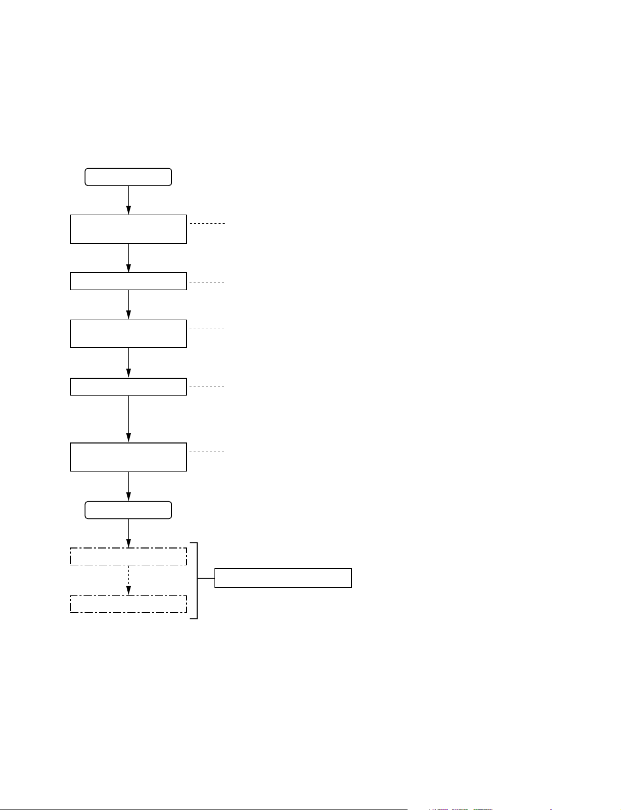
The following chart shows the procedure for installing the unit.
For details of the following chart, refer to the relevant section or related manual.
Start
Operating Environment
Selection of installation
place
1-2.
Power Supply
1-3.
Installation Space
1-4.
Rack mounting
Installation of optional
boards
Connection
Setting the On-Board
Switches
End
Initial setting
Rack Mounting
1-5.
Installation of Optional Boards
1-6.
Matching Connectors and Cables
1-7.
Input and Output Signals of Connectors
1-8.
System Connection
1-9.
How to Extend Inputs and Outputs
1-10.
Setting the On-Board Switches and
1-11.
Description of LEDs
System Setup Manual
Operation check
HDS-X5800
1-1 (E)
1-2. Operating Environment
1-3. Power Supply
1-2. Operating Environment
w
Do not install the unit in a place subject to excessive oil
vapor, steam, moisture, or dust, otherwise a fire or electric
shock may result.
m
. To prevent the temperature rising inside the unit, ensure
there is adequate circulation of air near where the unit is
installed. Never block the ventilation holes.
. Never install the unit near a heat source.
Operating temperature : 5 dC to 40 dC
Storage temperature : _20 dC to +60 dC
Operating humidity : 10% to 90% (no condensation)
1-3. Power Supply
The HDS-X5800 contains the four power supply units as
the standard installation.
The units A1 and B1, and the units A2 and B2 back up the
two power line systems respectively. Therefore, turn on all
of the four power supply units when using the HDSX5800.
(Refer to Section 2-1 for the location of the power supply
units.)
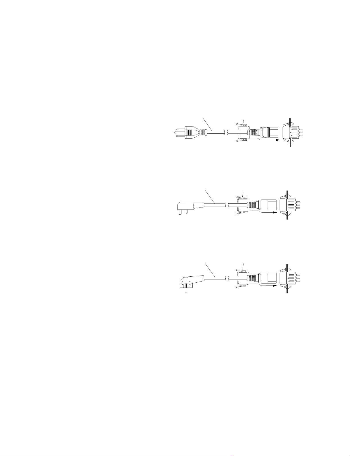
1-3-2. Power Cord
w
The power cords are not supplied with the unit. Be sure to
use power cords that are suitable for the place of operation.
For customers in the U.S.A. and Canada
1 Power cord, 125 V 10 A (2.4 m) : ! 1-557-377-11
2 Plug holder (Black) :
1
For customers in the United Kingdom
1 Power cord, 250 V 10 A (2.4 m) : ! 1-782-165-11
2 Plug holder (Brown) :
1
For customers in European countries except the United Kingdom
1 Power cord, 250 V 10 A (2.0 m) : ! 1-551-631-22
2 Plug holder (Brown) :
1
2
2
2
2-990-242-01
AC inlet
3-613-640-01
AC inlet
3-613-640-01
AC inlet
1-3-1. Power Specifications
Power requirements AC 100 to 240 V ± 10%
Power frequency 50/60 Hz
Current consumption AC100 V : 12 A (max.)
AC240 V : 4 A (max.)
Inrush current
Power consumption 1200 VA (max.)
n
The capacity of the AC power must be commensurate with
the inrush current. If the capacity of the AC power is not
sufficiently large, the breaker of the AC power on the
supply side will trip or the unit will not operate normally.
At power voltage of 100 V : 60 A
(Maximum when all of the four
power supply units are turned on)
At power voltage of 240 V : 85 A
(Maximum when all of the four
power supply units are turned on)
n
For the customer outside of the area as shown above,
please contact your local Sony Sales Office/Service
Center.
1-2 (E)
HDS-X5800
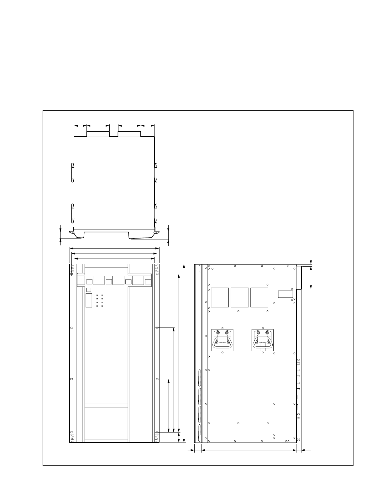
1-4. Installation Space
m
. The rear side of the unit should be at least 40 cm (16 inches) away from walls for ventilation and
maintenance.
. If a fan stops or the exhaust port is blocked, failure or problems may result because the fans at the rear,
top, and bottom of the unit cool the air.
1-4. Installation Space
72 72
31
48124 124
482
465
440
35
13
124
HDS-X5800
562
282.6
844.6
974 (22 U)
64.7
35
520
29
Unit : mm
1-3 (E)

1-5. Rack Mounting
1-5. Rack Mounting
The HDS-X5800 is mounted in the 19-inch standard rack.
To mount the HDS-X5800 in the rack, use the rack mount
kit that is supplied with the HDS-X5800 and follow the
procedure described below.
n
If other than the specified rack mount kit is used, the HDSX5800 may not be mounted in the 19-inch standard rack.
Parts of the supplied rack mount kit
. Support angle 2 pcs
. Bracket 4 pcs
. Support angle fixing screw 8 pcs
(PSW4 x 10 : 7-682-962-01)
. Bracket fixing screw 8 pcs
(B4 x 10 : 7-682-562-04)
Other required parts
To mount in the rack, the supplied rack mount parts and
the following part are required.
. Screw for rack mounting 4 pcs
(B5 x 12 : 7-682-576-04)
1-5-1. Precautions for Rack Mounting
w
. Be sure to mount in the rack with four persons or more.
. Mount in the rack in a stable position.
. To prevent the rack from falling or moving, fix the rack
on a flat and steady floor using bolt or others.
If the rack falls due to the weight of the equipment, it
may cause death or injury.
. After rack mounting, be sure to tighten the screws on the
rack angle and fix the unit in the rack.
If the screws on the rack angle are not tightened, the unit
may slip from the rack and fall, causing injury.
c
When mounting the unit in the rack, note the following:
. Be sure to use the supplied rack mount kit.
If not, injury may result and the equipment may fall due
to insufficient strength.
. Be careful not to catch your fingers or hands in the rack
mount rail or others.
n
If several units are mounted in a rack, it is recommended to
install a ventilation fan to prevent temperature rise inside
the rack.
1-4 (E)
HDS-X5800
1-5. Rack Mounting
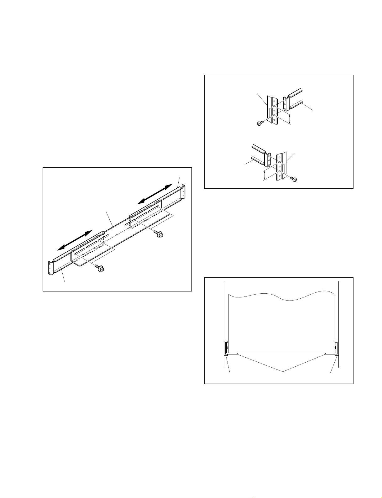
1-5-2. Rack Mounting Procedure
This section describes the rack mounting procedure using
the rack mount kit supplied with the HDS-X5800.
n
Tighten the screws to the following torque.
Tightening torque : 120 x 10_2 N.m {12.2 kgf.cm}
1. Attach the bracket to the support angle tentatively
using the specified four screws.
2. Loosen the front and rear screws that are tentatively
fastened in step 1. Adjust the length of the brackets
according to the depth of the rack.
(The illustration below shows the left bracket.)
Bracket
Support angle
PSW4 x 10
PSW4 x 10
3. Attach the right and left brackets to the rack completely using the specified eight screws.
(The illustration below shows the left bracket.)
Front side
Rack
Bracket
31.75
B4 x 10
Rear side
Rack
Bracket
31.75
B4 x 10
Unit : mm
4. Tighten the screws (four screws each on the right and
left) for adjusting the length of the bracket completely
(the screws that were loosened in step 2).
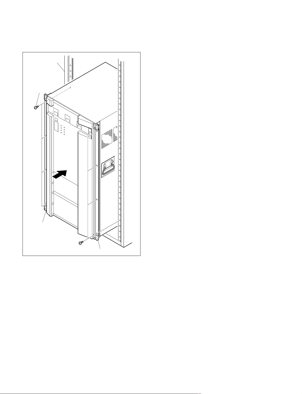
5. Place the right and left ends of the bottom of the HDSX5800 on top of the support angles, and slide the
equipment to the rear.
n
The support angles support the bottom of the HDSX5800 as shown below.
Bracket
n
Maximum depth of bracket : 750 mm
Minimum depth of bracket : 595 mm
Bracket Bracket
Support angles
HDS-X5800
1-5 (E)
1-5. Rack Mounting
6. Fix the rack angle in the rack using the specified eight
screws.
Rack
B5 x 12
Rack angle
B5 x 12
Rack angle
1-6 (E)
HDS-X5800

1-6. Installation of Optional Boards
1-6. Installation of Optional Boards
m
The usable optional boards are different depending on the type of signal to handle.
. The HKS-58xxM is the optional board that supports multi-bit rate signal including the HDTV SDI signal.
For the signal system that handles the HDTV SDI signal, use the HKS-58xxM boards for all the optional boards starting
from input to up to output.
. For the signal system that handles the 270 Mbps serial bit stream signal conforming to the DVB-ASI standard, use the
HKS-5830M board for the matrix board. If the HKS-5830SD board is used, an error may occur in the signal.
. To use the HKS-58xxM board, the software in the CPU-339 board in the HDS-X5800 should be upgraded to version 1.20
or higher.
Type of signal Input board Distribution Matrix board Output board Input expansion
HDTV SDI signal HKS-5810M HKS-5820M HKS-5830M HKS-5860M HKS-5811M
SDTV SDI signal HKS-5810SD/5810M HKS-5820M HKS-5830SD/5830M HKS-5860SD/5860M HKS-5811SD/5811M
DVB-ASI signal HKS-5810SD/5810M HKS-5820M HKS-5830M HKS-5860SD/5860M HKS-5811SD/5811M
1-6-1. Table of Optional Boards
There are the following optional boards for the HDS-X5800.
board board
1-6-2. List of Installation Slots
The HDS-X5800 can be configured to the various configurations in order to support the various systems and to expand
Option name Board configuration
33 INPUT BOARD SET
HKS-5810M
HKS-5810SD
34 CASCADE INPUT
BOARD SET
HKS-5811M Plug-in board : EQ-91 1 pc
HKS-5811SD Plug-in board : EQ-92 1 pc
33 INPUT DISTRIBUTION
BOARD
HKS-5820M Plug-in board : IPM-98 1 pc
264 x 34 MATRIX BOARD
HKS-5830M Plug-in board : MX-103 1 pc
HKS-5830SD Plug-in board : MX-104 1 pc
34 OUTPUT BOARD SET
HKS-5860M
HKS-5860SD
HDS-X5800
Connector board : CNI-11 1 pc
Connector board : CNI-12 1 pc
Connector board : CNI-13 1 pc
Connector board : CNI-14 1 pc
Connector board : CI-29 2 pcs
Connector board : CI-29 2 pcs
Connector board : CNO-13 1 pc
Connector board : CNO-14 1 pc
Connector board : CNO-15 1 pc
Connector board : CNO-16 1 pc
the functions. Select a proper combination of the plug-in
boards and connector boards for these purposes. The
respective boards have the specified slots to which they must
be inserted. Therefore, confirm that the respective boards are
inserted into the specified slots correctly as follows.
For the installation method of the respective boards, refer
to “1-6-3. Installation/Removal of Plug-in Boards” and
“1-6-4. Installation/Removal of Connector Boards”.
n
If any plug-in board or connector board is inserted into
wrong slot, the system error occurs and the HDS-X5800
will not work properly.
Board name
CI-29 _ CASCADE IN slot
CNI-11 _ IN 1 slot
CNI-12 _ IN 2 slot
CNI-13 _ IN 1 slot
CNI-14 _ IN 2 slot
CNO-13 _ OUT 1 slot
CNO-14 _ OUT 2 slot
CNO-15 _ OUT 1 slot
CNO-16 _ OUT 2 slot
EQ-91 Connect it to the _
EQ-92 Connect it to the _
IPM-98 1 IN to 8 IN slot _
MX-103 1 OUT to 8 OUT slot _
MX-104 1 OUT to 8 OUT slot _
Slots of the front side
MX-103 board.
MX-104 board.
Slots of the rear side
1-7 (E)
1-6. Installation of Optional Boards
1-6-3.
Installation/Removal of Plug-in Boards
c
Before installing or removing the boards, be sure to turn
off the power switches and disconnect all of the power
cords (4 cords) from the wall outlet. If the board is attached or removed with the power on, an electric shock
may result or the board may be damaged.
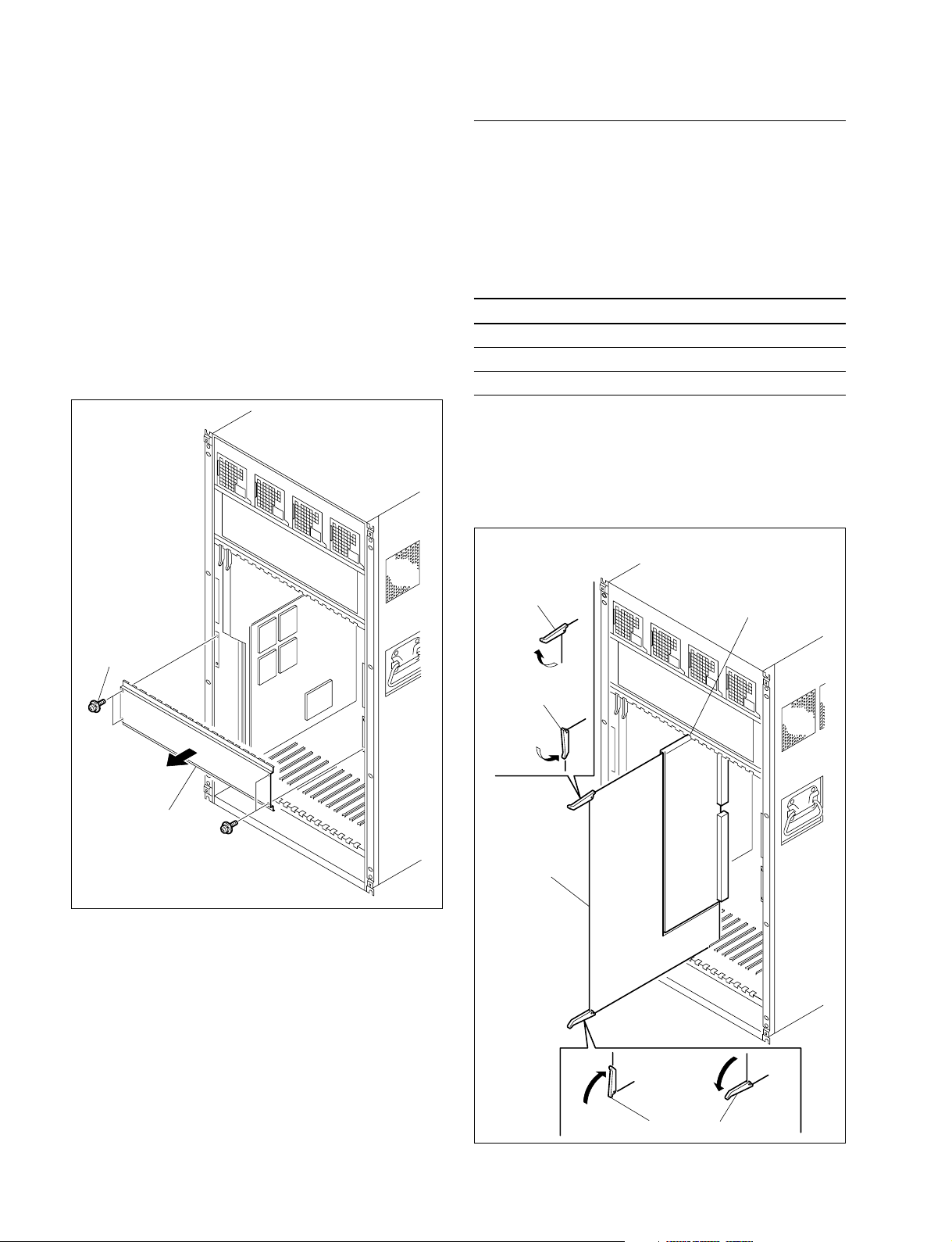
On the front panel side
1. Remove the front panel. (Refer to Section 2-2.)
2. Remove the four screws, and then remove the board
retainer plate.
HKS-5820M/5830M/5830SD
Installation
1. With the eject lever opened, insert the desired board
into the corresponding slot.
n
Insert the board while applying equal force to the eject
levers at both ends of the board.
Model name Board name Installation slot
HKS-5820M IPM-98 IN slot
HKS-5830M MX-103 OUT slot
HKS-5830SD MX-104 OUT slot
2. While closing the eject levers in the direction of the
arrow A, push in the board.
n
Check that the board is securely connected to the MB939 board.
(In the case of the HKS-5820M)
PSW3 x 6
Board retainer plate
Eject lever
IN slot
B
Eject lever
A
PSW3 x 6
IPM-98 board
1-8 (E)
A
B
Eject levers
3. Attach the board retainer plate and the front panel.
HDS-X5800
1-6. Installation of Optional Boards
Removal
1. Open the eject levers of the board in the direction of
arrow B.
2. Remove the board from the HDS-X5800.
n
Remove the board while applying equal force to the eject
levers at both ends of the board.
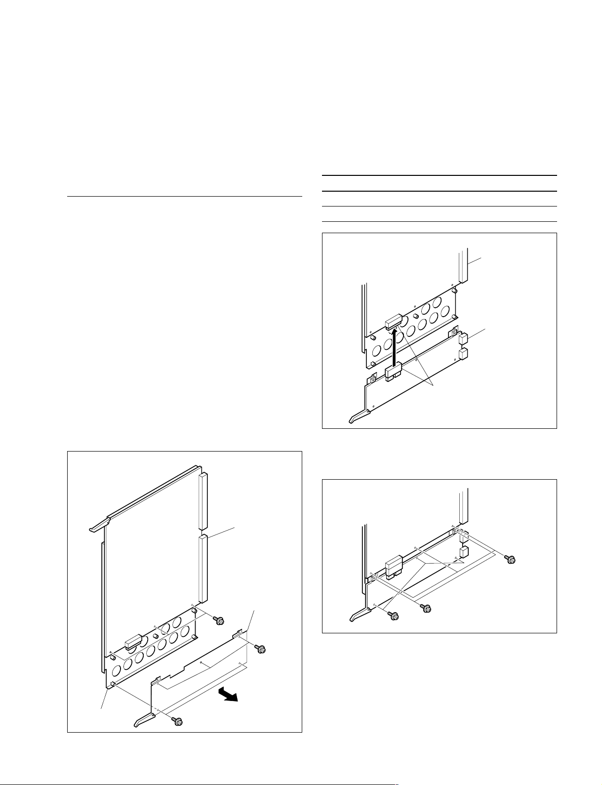
HKS-5811M/5811SD (EQ Board)
The HKS-5811M/5811SD consists of the two types of the
boards : EQ board (EQ-91 board/EQ-92 board) and CI-29
boards.
Installation and removal of the EQ board are described below.
For the CI-29 board, refer to Section 1-6-4.
n
When
the EQ board
is going to be installed in the existing
MX board (MX-103/MX-104 board), remove the MX board
from the slot beforehand. (Refer to this section “HKS5820M/5830M/5830SD”.)
2. Install the desired board into the corresponding shield
plate.
m
. When inserting the EQ board, be careful that the
side-B (soldering side) of the EQ board must not
touch the shield plate.
. Check that the EQ board is securely connected.
Model name Board name Installation slot
HKS-5811M EQ-91 Shield plate of the MX-103 board
HKS-5811SD EQ-92 Shield plate of the MX-104 board
(In the case of the HKS-5811SD)
MX-104 board
EQ-92 board
Installation
1. Remove the eight screws and remove the board
bracket (MX).
n
Keep the removed board bracket (MX).
(In the case of the HKS-5811SD)
MX-104 board
Board bracket (MX)
PSW3 x 6
PSW3 x 6
Connectors
3. Secure the EQ board with the eight screws removed in
step 1.
PSW3 x 6
PSW3 x 6
PSW3 x 6
4. Install the MX board.
(Refer to this section “
HKS-5820M/5830M/5830SD
”.)
Shield plate (MX)
HDS-X5800
Removal
Remove it by reversing the installation procedure.
PSW3 x 6
1-9 (E)
1-6. Installation of Optional Boards
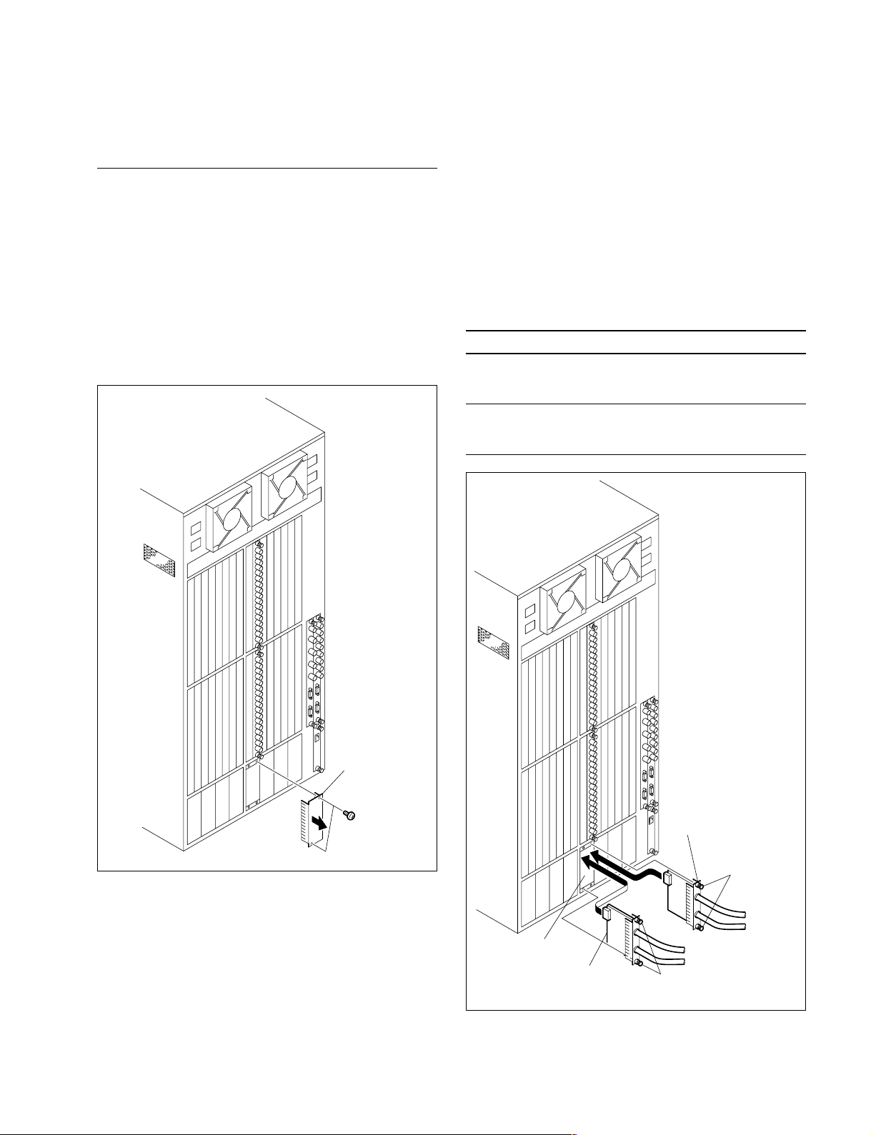
1-6-4. Installation/Removal of Connector
Boards
c
Before installing or removing the boards, be sure to turn
off the power switches and disconnect all of the power
cords (4 cords) from the wall outlet. If the board is attached or removed with the power on, an electric shock
may result or the board may be damaged.
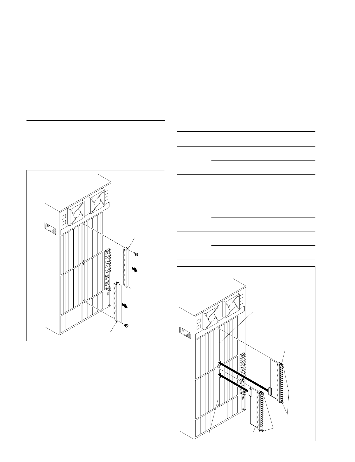
HKS-5810M/5810SD/5860M/5860SD
Installation
1.
Remove the four screws and remove the two blank panels.
n
Keep the removed blank panels.
Blank panel
B3 x 4
2. Insert the desired board into the corresponding slot and
tighten the two screws (with drop-safe) of the each
board.
m
. Insert the board while applying equal force to the
screws at both ends of the board.
. Check that the boards are securely connected to the
MB-939 board.
. Be careful not to turn them upside down by
observing the top and bottom of these boards when
installing the each board.
Option name Board Installation slot
HKS-5810M CNI-11 The IN1 slot of the same position as
HKS-5810SD CNI-13 The IN1 slot of the same position as
HKS-5860M CNO-13 The OUT1 slot of the same position
HKS-5860SD CNO-15
name
in the HKS-5820M (IPM-98 board)
CNI-12 The IN2 slot of the same position as
CNI-14 The IN2 slot of the same position as
CNO-14 The OUT2 slot of the same position
CNO-16
in the HKS-5820M (IPM-98 board)
in the HKS-5820M (IPM-98 board)
in the HKS-5820M (IPM-98 board)
as in the HKS-5830M (MX-103 board)
as in the HKS-5830M (MX-103 board)
The OUT1 slot of the same position as
in the HKS-5830SD (MX-104 board)
The OUT2 slot of the same position as
in the HKS-5830SD (MX-104 board)
1-10 (E)
Blank panel
B3 x 4
(In the case of the HKS-5810SD)
IN 2 slot
CNI-14 board
IN 1 slot
CNI-13 board
Screws
(with drop-safe)
Screws
(with drop-safe)
HDS-X5800
CI-29 board
CI-29 board
Screws
(with drop-safe)
Screws
(with drop-safe)
CASCADE IN slot
1-6. Installation of Optional Boards
Removal
Remove them by reversing the installation procedure.
HKS-5811M/5811SD (CI-29 Board)
The HKS-5811M/5811SD consist of the two types of the
boards: EQ board and CI-29 boards. Installation and
removal of the CI-29 board are described below.
For the EQ board, refer to Section 1-6-3.
Installation
1. Remove the two screws and remove the blank panel.
n
Keep the removed blank panel.
2. Insert a pair of CI-29 boards to the CASCADE IN slot
and tighten the two screws (with drop-safe) of the each
board.
m
. Insert the board while applying equal force to the
screws at both ends of the board.
. Check that the boards are securely connected to the
MB-939 board.
. Be careful not to turn them upside down by
observing the top and bottom of these boards when
installing the each board.
Option name Board name Installation slot
HKS-5811M CI-29 board
(2 boards IN slot of the same position as
as a pair) in the MX-103 board.
HKS-5811SD CI-29 board
(2 boards IN slot of the same position as
as a pair) in the MX-104 board.
Connector side, The CASCADE
Connector side, The CASCADE
HDS-X5800
Blank panel
B3 x 4
Removal
Remove it by reversing the installation procedure.
1-11 (E)

1-7. Matching Connectors and Cables
1-7. Matching Connectors and Cables
To connect the cable to the unit, use the following connectors and cables or their equivalents.
Model name/panel indication Connector name Application connector/cable
Name Sony part No.
HDS-X5800
REMOTE1 A /B1/B2/C/D BNC, 75 Z BNC, 75 Z_
REF IN A/B/C/D BELDEN 8281 cable
HKS-5810SD
SDTV Serial VIDEO INPUT 1 to 33
HKS-5860SD
SDTV Serial VIDEO OUTPUT 1 to 34
HKS-5810M
Serial VIDEO INPUT 1 to 33 BNC, 75 Z BNC, 75 Z_
HKS-5860M BELDEN 1694 cable
Serial VIDEO OUTPUT 1 to 34
HDS-X5800
REMOTE2 A/B D-sub 9-pin, Female D-sub 9-pin, Male
Connector 9-pin Male 1-560-651-00
Junction Shell 9-pin 1-561-749-00
HDS-X5800
REMOTE3 D-sub 9-pin, Male D-sub 9-pin, Female
Connector 9-pin Female 1-563-815-21
Junction Shell 9-pin 1-561-749-00
HDS-X5800
ALARM D-sub Mini 15-pin, Female D-sub Mini 15-pin, Male _
HDS-X5800
DATA RJ-45 modular jack 100BASE-TX standard _
*1 : The following crimp contact is required for the plug.
AWG#18 to #22 : 1-566-493-21
AWG#22 to #24 : 1-564-774-11
AWG#24 to #30 : 1-564-775-11
*1
1-12 (E)
HDS-X5800

_ EXT VIEW _
1
5
11
15
6
10
1-8. Input and Output Signals of Connectors
1-8. Input and Output Signals of
Connectors
The input and output signals of the connectors at the rear
panel are as follows.
REMOTE2 A/B : RS-422A (D-sub 9-pin, Female)
5
_ EXT VIEW _
Pin No. Signal name Input/Output Function
1FG _ Frame ground
2 TX (_) O Transmitted data (_)
3 RX (+) I Received data (+)
4 GND _ Common ground
5 __No connection
6 GND _ Common ground
7 TX (+) O Transmitted data (+)
8 RX (_) I Received data (_)
9 __No connection
The frame ground and the common ground are connected
internally inside the system.
REMOTE3 : RS-232C (D-sub 9-pin, Male)
1
69
ALARM : D-sub Mini 15-pin, Female
Pin No. Signal name Input/Output Function
1 ALARM-3 O Alarm drive-3
2 ALARM-1 O Alarm drive-1
3 ALARM-4 O Alarm drive-4
4GND _ Ground
5 ALARM-5 O Alarm drive-5
6 to 8 GND _ Ground
9 ALARM-6 O Alarm drive-6
10 GND _ Ground
11 GND _ Ground
12 ALARM-2 O Alarm drive-2
13 to 15 GND _ Ground
n
Specifications of the alarm output
Open collector output
Voltage that can be applied to the terminal : 0 to 20 V
Pull-in current :
Maximum 50 mA when the output transistor is
saturated (output terminal voltage is 1 V or less).
Output terminal voltage x pull-in current < 50 mV
when the output transistor is non-saturated.
1
5
DATA :
96
_ EXT VIEW _
Pin No. Signal name Input/Output Function
1 DCD I Date carrier detect
2 RX I Received data
3 TX O Transmitted data
4 DTR O Data terminal ready
5 GND _ Signal ground
6 DSR I Date set ready
7 RTS O Request to send
8 CTS I Clear to send
9 __No connection
Pin-6 (DSR) is connected to pin-1 (DCD) internally inside
the system.
HDS-X5800
10BASE-T/100BASE-TX (RJ-45 8-pin Modular jack)
1
_ EXT VIEW _
Pin No. Signal name Input/Output Function
1 TDB O Transmitted data B
2 TDA O Transmitted data A
3 RDB I Received data B
4 BI_D3+_ (*1)
5 BI_D3__ (*1)
6 RDA I Received data A
7 BI_D4+_ (*1)
8 BI_D4__ (*1)
*1 : This signal line is not used in this system. It is connected to the
termination circuit inside the system.
8
1-13 (E)
 Loading...