

Sony HDS-7100 User Manual

Operation Software
HZS-7060
User’s Guide
HD Digital Video Switcher
HDS-7100
Volume 2
1st Edition
Software Version 1.00 and Later
English

NOTICE TO USERS
© 2000 Sony Corporation. All rights reserved. This manual
or the software described herein, in whole or in part, may
not be reproduced, translated or reduced to any machine
readable form without prior written approval from Sony
Corporation.
SONY CORPORATION PROVIDES NO WARRANTY WITH
REGARD TO THIS MANUAL, THE SOFTWARE OR
OTHER INFORMATION CONTAINED HEREIN AND
HEREBY EXPRESSLY DISCLAIMS ANY IMPLIED
WARRANTIES OF MERCHANTABILITY OR FITNESS FOR
ANY PARTICULAR PURPOSE WITH REGARD TO THIS
MANUAL, THE SOFTWARE OR SUCH OTHER
INFORMATION. IN NO EVENT SHALL SONY
CORPORATION BE LIABLE FOR ANY INCIDENTAL,
CONSEQUENTIAL OR SPECIAL DAMAGES, WHETHER
BASED ON TORT, CONTRACT, OR OTHERWISE,
ARISING OUT OF OR IN CONNECTION WITH THIS
MANUAL, THE SOFTWARE OR OTHER INFORMATION
CONTAINED HEREIN OR THE USE THEREOF.
Sony Corporation reserves the right to make any
modification to this manual or the information contained
herein at any time without notice.
The software described herein may also be governed by
the terms of a separate user license agreement.

Table of Contents
Chapter 1
Overview
Chapter 2
Location and
Function of
Parts
Chapter 3
ThreeDimensional
Transformations
(Continued)
HDS-7100 System Introduction............................................... 1-2
System Configuration...................................................... 1-2
Operation Software ......................................................... 1-3
Features ........................................................................... 1-5
Channel Assignments ............................................................... 1-7
Starting Up and Powering Off................................................. 1-8
Examples of DME Effects ........................................................ 1-9
Three-Dimensional Transformations .............................. 1-9
Background and Edge Effects ....................................... 1-10
Freeze and Afterimage Effects...................................... 1-10
Overall Image Effects ................................................... 1-11
Video Signal Effects ..................................................... 1-11
Nonlinear Effects .......................................................... 1-12
Control Panel ............................................................................ 2-2
Transformation Operation Section......................................... 2-3
Keyframe Operation Section ................................................... 2-6
Channel Selection Section...................................................... 2-10
Menu Operation Section ........................................................ 2-12
Numeric Keypad Section ....................................................... 2-14
Transformation Basics ............................................................. 3-2
Basic Procedure............................................................... 3-2
Source Coordinate Frame and Target Coordinate
Frame....................................................................... 3-4
Three-Dimensional Coordinates ..................................... 3-5
Specializing the Effect of the Trackball and Z-Ring ...... 3-7
Moving the Image ..................................................................... 3-9
Moving in the Source Coordinate Frame ........................ 3-9
Moving in the Target Coordinate Frame....................... 3-11
Rotating the Image ................................................................. 3-13
Rotating in the Source Coordinate Frame ..................... 3-13
Rotating in the Target Coordinate Frame...................... 3-15
Moving the Axes of Rotation ................................................. 3-17
Moving the Axes of Rotation in the Source Coordinate
Frame..................................................................... 3-17
Moving the Axes of Rotation in the Target Coordinate
Frame..................................................................... 3-19
Table of Contents
i

Table of Contents
Chapter 3
ThreeDimensional
Transformations
(Continued)
Chapter 4
Menu
Operations
Magnifying or Shrinking the Image ..................................... 3-21
Magnifying or Shrinking in the Source Coordinate
Frame..................................................................... 3-21
Magnifying or Shrinking in the Target Coordinate
Frame..................................................................... 3-22
Changing the Skew, Aspect Ratio or Perspective
of the Image..................................................................... 3-23
Changing the Skew or Aspect Ratio of the Image ........ 3-23
Changing the Perspective of the Image......................... 3-26
Setting the Number of Rotations (Spin Function) ............... 3-28
Menu Tree ................................................................................. 4-2
Menu Display and Basic Operations....................................... 4-4
Menu Display .................................................................. 4-4
Basic Menu Screen Operations ....................................... 4-5
Initial Screen ............................................................................. 4-8
Example Screen............................................................... 4-8
Basic Operations in the Initial Screen ............................. 4-8
Top Menu Screens .................................................................... 4-9
Example Screen............................................................... 4-9
Basic Operations in a Top Menu................................... 4-10
Parameter Setting Screens..................................................... 4-11
Example Screen............................................................. 4-11
Basic Operations in a Parameter Setting Screen ........... 4-12
Chapter 5
Special Effects
Operations
(Continued)
Table of Contents
ii
Quick Enabler........................................................................... 5-3
QUICK ENABLER Settings – 1..................................... 5-3
Auto Cube Function ................................................................. 5-5
Number of Channels ....................................................... 5-5
Creating, Moving, and Rotating a Cube.......................... 5-5
Creating, Moving, and Rotating a Slab ........................... 5-8
Background and Edge Effects ............................................... 5-10
Effect Selection – 10 ..................................................... 5-10
BKGD (Background) Settings – 11 .............................. 5-11
BORDER Settings – 12................................................. 5-13
CROP Settings – 13 ...................................................... 5-16
DROP SHADOW Settings – 14.................................... 5-18

Chapter 5
Special Effects
Operations
(Continued)
(Continued)
Freeze and Afterimage Effects .............................................. 5-20
Effect Selection – 20 ..................................................... 5-21
INPUT FREEZE Settings – 21 ..................................... 5-22
MOTION DECAY Settings – 22 .................................. 5-24
TRAIL Settings – 23 ..................................................... 5-27
WIND Settings – 24 ...................................................... 5-29
KEYFRAME STROBE Settings – 25........................... 5-31
MULTI FREEZE Settings – 26..................................... 5-32
Overall Image Effects............................................................. 5-34
Effect Selection – 30 ..................................................... 5-34
MULTI MOVE Settings – 31 ....................................... 5-35
DEFOCUS Settings – 32............................................... 5-36
BLUR Settings – 33 ...................................................... 5-37
DIM Settings – 34 ......................................................... 5-38
Video Signal Effects................................................................ 5-39
Effect Selection – 40 ..................................................... 5-39
POSTER (Posterization) & NEGA (Negative) Settings
– 41........................................................................ 5-40
SEPIA & MONO (Monochrome) Settings – 42 ........... 5-42
CONTRAST Settings – 43............................................ 5-43
MOSAIC Settings – 44 ................................................. 5-45
MASK Settings – 45 .................................................... 5-46
Nonlinear Effects .................................................................... 5-48
Effect Selection – 100 ................................................... 5-48
WAVE Settings – 101 ................................................... 5-51
MOSAIC GLASS Settings – 102.................................. 5-56
FLAG Settings – 103 .................................................... 5-56
RIPPLE Settings – 104.................................................. 5-57
RINGS Settings – 105 ................................................... 5-59
BROKEN GLASS Settings – 106................................. 5-60
FLYING BARS Settings – 107..................................... 5-61
SPLIT Settings – 108 .................................................... 5-62
SPLIT SLIDE Settings – 109 ........................................ 5-63
CHARACTER TRAIL Settings – 110 .......................... 5-65
MIRROR Settings – 111 ............................................... 5-66
LENS Settings – 112 ..................................................... 5-67
CIRCLE Settings – 113................................................. 5-68
PANORAMA Settings – 114 ........................................ 5-69
Table of Contents
iii

Table of Contents
Chapter 5
Special Effects
Operations
(Continued)
Chapter 6
Input/Output
Signal
Operations
Chapter 7
Keyframe
Effects
(Continued)
PAGETURN Settings – 120.......................................... 5-70
ROLL Settings – 121 .................................................... 5-72
CYLINDER Settings – 122........................................... 5-73
SPHERE Settings – 123 ................................................ 5-75
RIPPLE 2 Settings – 130............................................... 5-76
TWIST Settings – 131................................................... 5-78
EXPLOSION Settings – 132......................................... 5-80
SWIRL Settings – 133 .................................................. 5-82
BLIND Settings – 134................................................... 5-84
KALEIDOSCOPE Settings – 135................................. 5-86
MULTI MIRROR Settings – 136 ................................. 5-88
MELT Settings – 137 .................................................... 5-89
Lighting ................................................................................... 5-92
Effect Selection – 300 ................................................... 5-93
LIGHTING Settings – 301............................................ 5-93
DME Selection and Input/Output Signals.............................. 6-2
Selecting Input/Output Operations – 50................................. 6-3
Video Signal and Key Signal Settings – 51 ............................. 6-4
Inverting the Input Signal – 55................................................ 6-6
Overview.................................................................................... 7-2
Keyframes and Effects .................................................... 7-2
Basic Procedure............................................................... 7-3
Registers and Channels ............................................................ 7-4
Accessing Registers ........................................................ 7-4
Channel Selection............................................................ 7-6
Generating and Editing Keyframes ........................................ 7-7
Creating New Keyframes ................................................ 7-7
Parameter Settings Which Can Be Included in
Keyframes ............................................................... 7-8
Editing Keyframes .......................................................... 7-9
Time Settings ................................................................ 7-16
Path Settings............................................................................ 7-18
Selecting Settings – 60 .................................................. 7-18
Basic Operations for Path Settings – 61 to 68............... 7-20
Spline Curve Settings .................................................... 7-22
Table of Contents
iv

Chapter 7
Keyframe
Effects
(Continued)
Executing Effects .................................................................... 7-27
Saving Effects.......................................................................... 7-28
Effect Run Mode Settings – 71 .............................................. 7-29
Chapter 8
Effect Utilities
Chapter 9
Status
Displays
Effect Utility Selection – 70...................................................... 8-2
Register Utilities........................................................................ 8-4
Register Operations – 72 ................................................. 8-4
Changing Register Names – 73..................................... 8-10
Channel-to-Channel Register Copy – 74 ...................... 8-12
Disk Utilities ............................................................................ 8-14
Overview ....................................................................... 8-14
Floppy Disk Operations – 77 ........................................ 8-15
Color Mattes – 78.................................................................... 8-25
Snapshots................................................................................. 8-27
Overview ....................................................................... 8-27
Snapshot Operations – 75.............................................. 8-28
Changing Snapshot Names – 76 ................................... 8-32
Channel-to Channel Snapshot Copy – 79 ..................... 8-33
Memory Recall........................................................................ 8-34
Memory Recall Selection – 500 .................................... 8-34
Memory Recall Panel Operations – 501 ....................... 8-35
Memory Recall Setup Operations – 502 ....................... 8-37
Selecting Status Display – 600 ................................................. 9-2
Three-Dimensional Transformation Status
Display – 601 ..................................................................... 9-3
Keyframe Three-Dimensional Transformation
Parameter Display – 602 .................................................. 9-4
Mouse-Driven Three-Dimensional Transformation
Operations – 606 ............................................................... 9-6
Keyframe Effect Timeline Status Display – 610 .................... 9-8
Table of Contents
v

Table of Contents
Chapter 10
Setup
Operations
Selecting Setup Items – 700 ................................................... 10-2
Global Channel Settings – 701............................................... 10-5
Settings Related to Operation – 702...................................... 10-7
Adjusting the Trackball and Z-Ring – 703 ........................ 10-10
Setting Up the GPI – 704...................................................... 10-13
FREZE Button Settings – 705 ............................................. 10-16
Screen Saver Setting – 706................................................... 10-18
Settings Related to Operation 2 – 707................................. 10-19
Automatic Key Selection Settings – 713 ............................. 10-21
Signal Processing Settings – 716.......................................... 10-23
Signal Processing Settings 2 – 717....................................... 10-25
System Settings – 721 ........................................................... 10-26
System Configuration Screen – 722 .................................... 10-28
Displaying the Software Version – 723 ............................... 10-29
Software Installation ............................................................ 10-30
Installing the Software in the Control Panel ............... 10-31
Installing the Software in the Processor – 724............ 10-32
Settings for the DME LINK™ Function – 725 .................. 10-34
Spare Port Settings – 726 ..................................................... 10-35
Index ........................................................................................... I-1
Table of Contents
vi

Chapter 1
Overview
HDS-7100 System Introduction............................................... 1-2
System Configuration ......................................................... 1-2
Operation Software............................................................. 1-3
Features............................................................................... 1-5
Channel Assignments ............................................................... 1-7
Starting Up and Powering Off................................................. 1-8
Examples of DME Effects ........................................................ 1-9
Three-Dimensional Transformations.................................. 1-9
Background and Edge Effects .......................................... 1-10
Freeze and Afterimage Effects ......................................... 1-10
Overall Image Effects ....................................................... 1-11
Video Signal Effects ......................................................... 1-11
Nonlinear Effects .............................................................. 1-12
1 Overview
HDS-7100 System Introduction
This manual is Volume 2 of the User’s Guide for the HZS-7060
Operation Software.
The User’s Guide consists of two volumes, and this volume covers
control of the HDS-7100 internal DME (option) from the BKDM3010 DME Control Panel Unit.
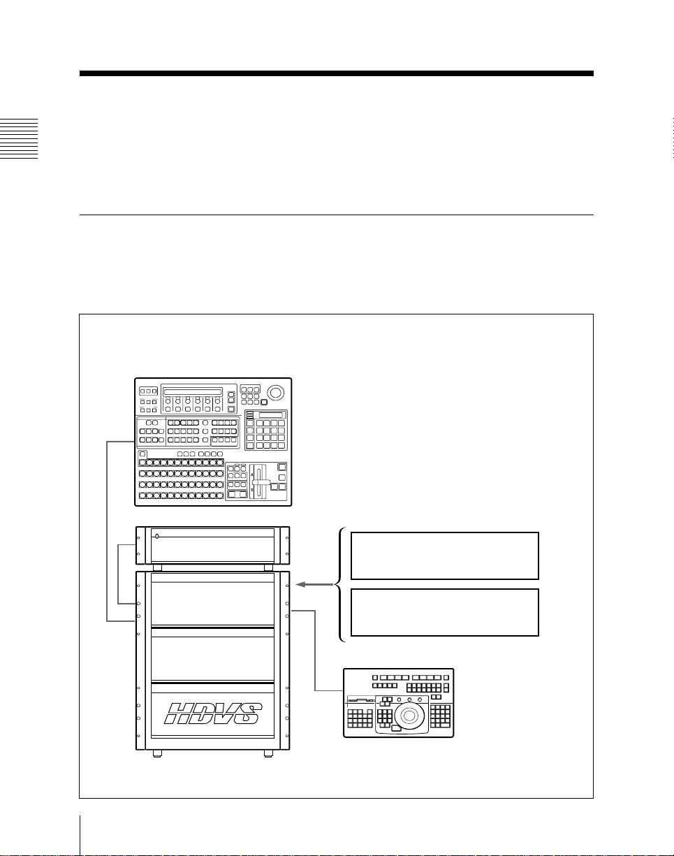
System Configuration
The following figure shows an example configuration of an HDS7100 system.
BKDS-2010 Switcher Control Panel
For details of operations from this panel,
refer to Volume 1.
1-2
HKDS-7695 Power Supply Unit
HDS-7100 High Definition
Digital Video Switcher
Chapter 1 Overview
Internal DME (option)
HKDS-7061 Video Modifier Board
HKDS-7071 Digital Multi Effects
Board
BKDM-3010 DME Control Panel
This manual (Volume 2) covers operations
from this panel.

Terms used in this manual
In this manual the following terms (other than product names) are
used to refer to this software product and related devices.
Term used in this manual Corresponding device and function
“Internal DME” or “DME” DME functions provided by installing HKDS-
“External DME” HDME-7000 High Definition Digital Multi
“DME control panel”
or “control panel”
“Switcher” HDS-7100 High Definition Digital
Menu monitor
7061 and HKDS-7071 in the switcher
Effects connected to the switcher
BKDM-3010 DME Control Panel Unit
Video Switcher
VGA Data Display Unit
Operation Software
The HZS-7060 Operation Software provides for control of an
HDS-7100 High Definition Digital Video Switcher and internal
DME function.
ROM packs, disks and manuals included in the HZS-7060
The following ROM packs, disks and User’s Guide volumes are
included in the product.
1 Overview
Label Contents
SYSTEM ROM PACK 1
SYSTEM ROM PACK 2 Switcher control panel software
SYSTEM DISK 1
SYSTEM DISK 2
User’s Guide Volume 1
User’s Guide Volume 2
(this manual)
Switcher processor software (including software
for the HKDS-7061)
Internal DME software (for the HKDS-7071)
Software for the BKDM-3010 DME Control Panel
Description of switcher operating procedures
Description of operating procedures for the
internal DME controlled from the BKDM-3010
DME Control Panel
Chapter 1 Overview
1-3

1 Overview
HDS-7100 System Introduction
Installing software, and User’s Guide volumes used
Use the disks and User’s Guide volumes included in the HZS-7060
according to the following table of objectives.
Objective Control
Operating
the switcher
Operating
the internal
DME
panel
BKDS-2010
BKDM-3010 DISK 1 and
ROM packs or
disks used
ROM PACK 1
and ROM
PACK 2
DISK 2
Software
installation
destination
BKDS-2010
Switcher
Control Panel
BKDM-3010
DME Control
Panel
User’s Guide
volume for
reference
Volume 1
Volume 2
For details of the method of installing DISK 1 and DISK 2 in the
BKDM-3010, see page 10-30 in this manual.
For ROM PACK installation procedure, refer to Volume 1.
Note
With the HDS-7100, you can use either an internal DME (HKDS7061 and HKDS-7071) or an external DME (HDME-7000 or
similar connected to the EXT DME 1 connector). However, it is
not possible to use both together.
To use an internal DME, in “PERIPH” of the SETUP menu, set
“DME” to “INT” (see Volume 1).
For the operations when an external DME is selected (“EXT”),
refer to the HZDM-7020 User’s Guide.
1-4
Chapter 1 Overview

Features
Installing the HKDS-7061 and HKDS-7071 in the HDS-7100
switcher allows you to use the internal DME function. This
provides the following features.
Three-dimensional image transformations
The system offers a range of three-dimensional processes both
with respect to the source coordinates (that is, the input video
space) and the target coordinates (that is, the video space of the
output), including shifting, rotation, and zoom functions. Smooth
and accurate manipulation is provided by the x-y track ball and Zring.
Special effects functions
The following are some of the special effects you can apply to a
video image:
• Background coloring and edge effects
• Freeze and strobe effects, using recursive memory functions, and
afterimage effects
• Overall image effects (“multi move,” and defocusing, for
example)
• Video and key signal transformations (negative image, mosaic
effects, etc.)
• Various nonlinear effects (waves, page turns, and so forth)
• Lighting effects
1 Overview
Keyframe effects
You can save DME image states and special effects as keyframes.
By building a series of keyframes for appropriate points on the
time axis, you can build and save an effect, for which the system
automatically provides the interpolation between each successive
pair of keyframes.
Simultaneous display of two menus
You can display two menus simultaneously on the screen. This
allows parallel display of the settings for two effects, or operations
in one menu while watching the status in another.
Chapter 1 Overview
1-5

1 Overview
HDS-7100 System Introduction
Quick menu access
The menus are arranged in a shallow hierarchy, with each group of
logically associated menus accessible from a single top-menu
button. Most on/off functions and parameter settings can be made
from a menu within one layer of top menu.
Each menu also has a page number, which makes it possible to
access any menu directly from menus in the other menu groups by
entering its page number from the numeric keypad.
Editor interfaces
It is possible to use an editing control unit such as the BVE-2000
or BVE-9100 connected to either the Sony 9-pin remote interface
or the GPI interface, for execution of key frame and other effects.
Note
The photographs and figures of screen examples in this User’s
Guide illustrate the case where the aspect ratio is set to the 4:3
mode. When the 16:9 mode is selected, the screen aspect ratio is
16:9.
1-6
Chapter 1 Overview

Channel Assignments
Channels which can be used
For the HDS-7100 internal DME function, the available DME
channels are automatically assigned as follows, depending on the
configuration of the HKDS-7061 Video Modifier Board and
HKDS-7071 Digital Multi Effects Board installation.
1 Overview
Channel
DME channel 1 Can be used.
DME channel 2 Can be used. This channel provides input freeze, picture
Global channel Can be used for the channel 1. Cannot be used.
Input video selection
Use the auxiliary buses of the switcher for input video to the
internal DME as follows.
Channel number
DME 1
DME 2
1) Tha same signal is input to DME 1 and DME 2.
Option Configuration
HKDS-7061 and HKDS-7071 HKDS-7061 only
Cannot be used.
This channel provides threedimensional transformations,
background and edge effects, picture
modifiers, video modifiers, nonlinear
effects, and so on.
modifiers, video modifiers, and other effects.
Application
Video input
Key input
External video input
Video input
Key input
External video input
Bus used
DME V (Press the VM V DME
V button.)
DME K (Press the VM K DME
K button.)
1)
DME VM EXT
VM V (Hold down the SHIFT
button and press the VM V
DME V button.)
VM K (Hold down the SHIFT
button and press the VM K
DME K button.)
1)
DME VM EXT
Chapter 1 Overview
1-7

1 Overview
Starting Up and Powering Off
Starting up
Powering on the processor and menu monitor starts the system,
and the initial screen (see page 4-8) appears on the menu monitor.
The system is now ready for control panel and menu operations.
Start-up state
It is possible to save function on/off settings and parameter values
in nonvolatile memory, and arrange to recall these settings
automatically when the system is started.
If no such setting is made, the system starts up with the factory
default settings.
For details see “OPERATION menu” on page 10-7.
Powering off
You can power off the system regardless of the current display on
the menu monitor.
Note
Do not power the unit off during any of the following operations.
• While a floppy disk is being accessed (see “Floppy Disk
Operations – 77” on page 8-15)
This may cause files on the floppy disk, or backup copies of data
in the processor (contents of effect registers or snapshot registers)
to be corrupted.
• During installation of the software (see “Installing the Software
in the Processor – 724” on page 10-32)
• While writing setup data
If the unit is powered off during operation, the data being written
may be corrupted. If you power the unit off inadvertently, restart
the system with the factory default settings, then make the required
settings or restore the settings by loading again from the floppy
disk.
1-8
Chapter 1 Overview
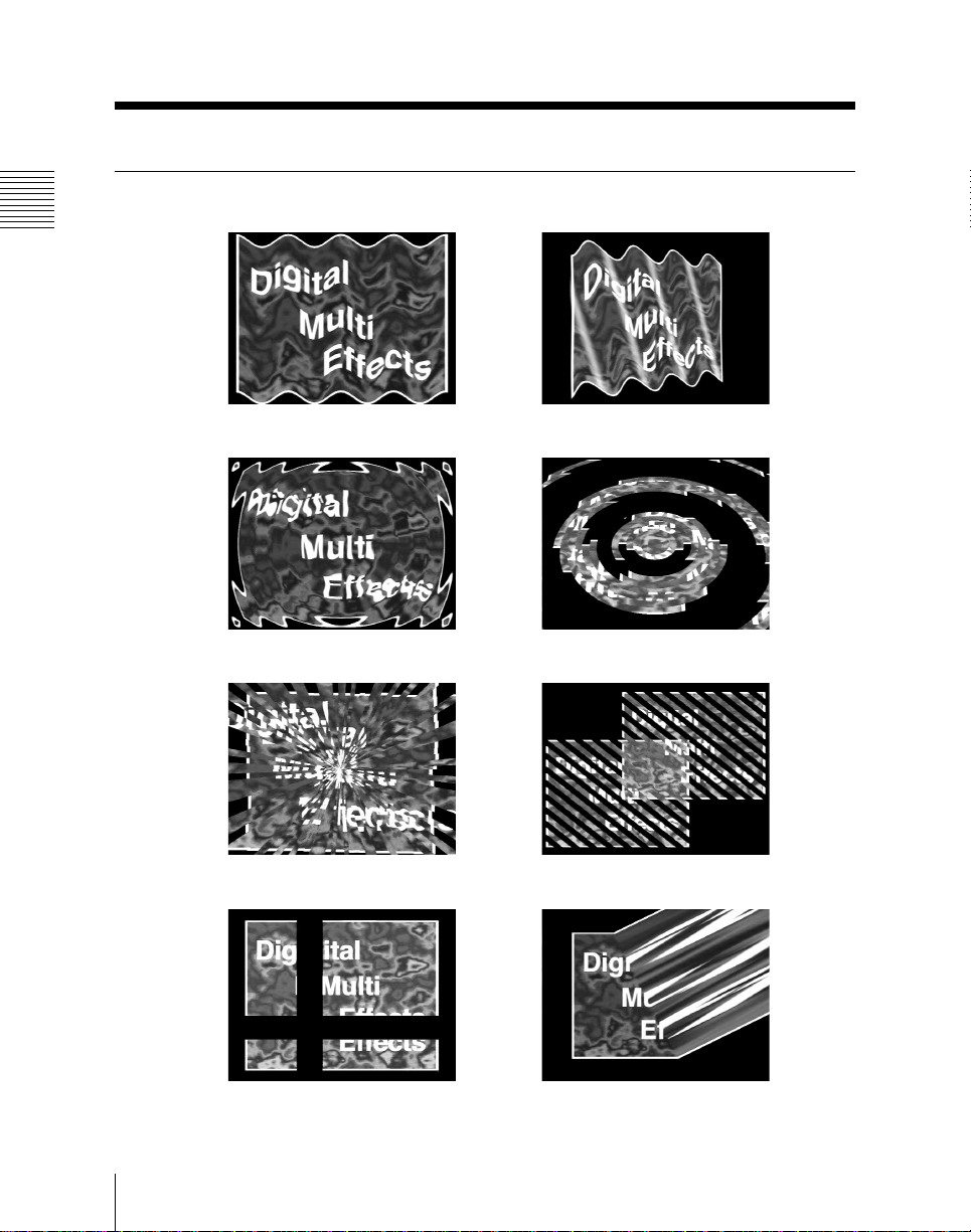
Examples of DME Effects
This section illustrates some of the effects which the internal DME
can produce, using photographs. It also refers to the page numbers
(in parentheses) on which the corresponding procedures are
described.
The following screen examples illustrate the case where the aspect
ratio is set to the 4:3 mode. When the 16:9 mode is selected, the
screen aspect ratio is 16:9. (See page 10-27.)
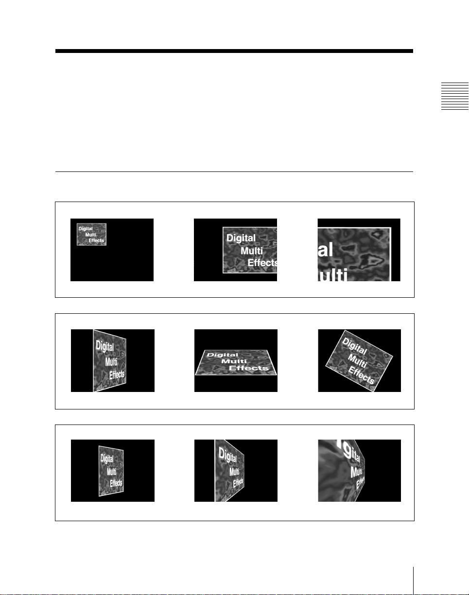
Three-Dimensional Transformations
kk
Displacement in 3-D space (page 3-9)
1 Overview
kk
Rotation in 3-D space (page 3-13)
kk
Perspective deformation (page 3-26)
Chapter 1 Overview
1-9
1 Overview
Examples of DME Effects
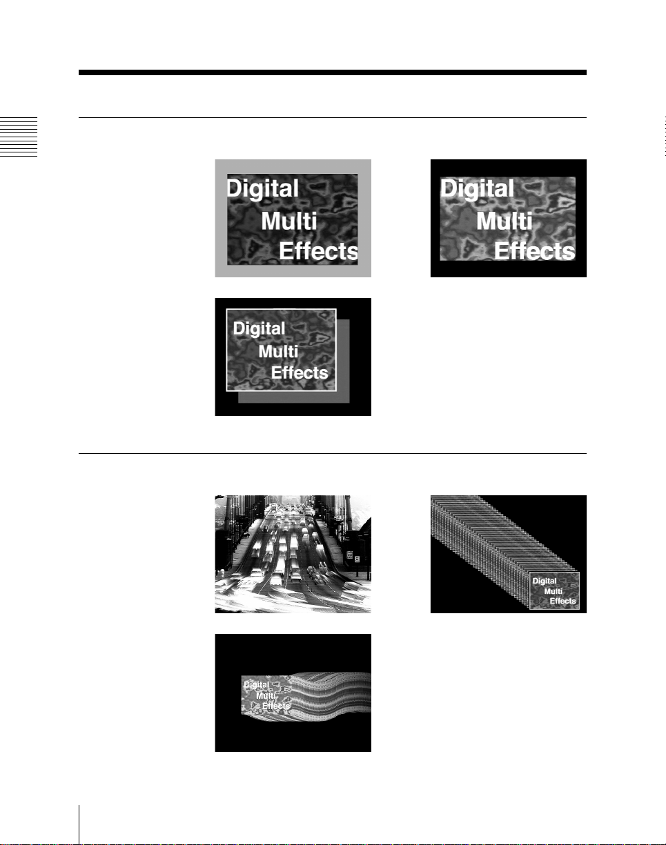
Background and Edge Effects
BORDER (page 5-13) CROP (page 5-16)
DROP SHADOW (page 5-18)
Freeze and Afterimage Effects
MOTION DECAY (page 5-24) TRAIL (page 5-27)
WIND (page 5-29)
1-10
Chapter 1 Overview
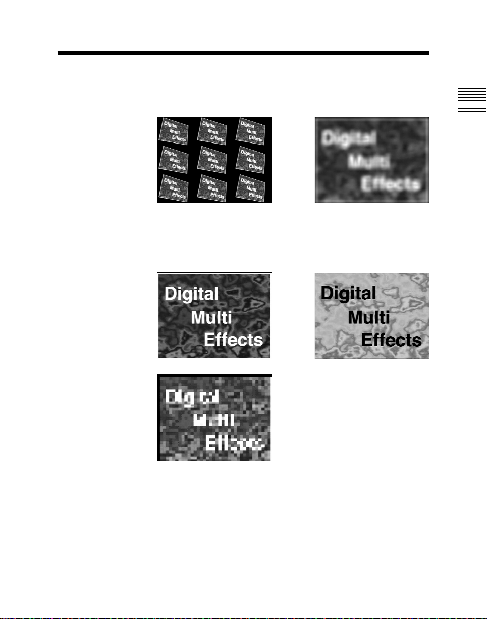
Overall Image Effects
MULTI MOVE (page 5-35) DEFOCUS (page 5-36)
Video Signal Effects
1 Overview
k
NEGA (page 5-40)
MOSAIC (page 5-45)
Chapter 1 Overview
1-11
1 Overview
Examples of DME Effects
Nonlinear Effects
WAVE (page 5-51) FLAG (page 5-56)
RIPPLE (page 5-57) RINGS (page 5-59)
1-12
BROKEN GLASS (page 5-60) FLYING BARS (page 5-61)
SPLIT (page 5-62) CHARACTER TRAIL (page 5-65)
Chapter 1 Overview
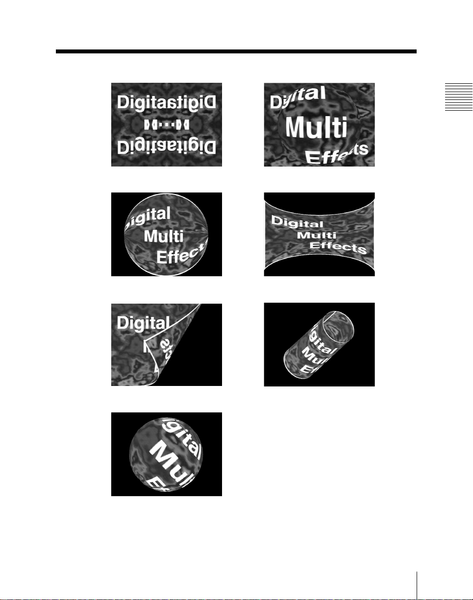
MIRROR (page 5-66) LENS (page 5-67)
CIRCLE (page 5-68) PANORAMA (page 5-69)
PAGETURN (page 5-70) CYLINDER (page 5-73)
1 Overview
SPHERE (page 5-75)
Chapter 1 Overview
1-13

Chapter 2
Location and Function of Parts
Control Panel ............................................................................ 2-2
Transformation Operation Section......................................... 2-3
Keyframe Operation Section ................................................... 2-6
Channel Selection Section ...................................................... 2-10
Menu Operation Section ........................................................ 2-12
Numeric Keypad Section ....................................................... 2-14

Control Panel
The control panel is divided into a number
of blocks, as shown in the following
figure. A page number in parenthesis after
a block name indicates the page on which
a more detailed description starts.
Channel selection section
2 Location and Function of Parts
EDIT
ENABL
RUN REW REVS
CNST
DUR
SHIFT
Keyframe operation section
KF
RECAL
EFF
KF
DUR
EFF
PREVKFNEXT
(page 2-6)
(page 2-10)
STORE
EFF
STP
NEXT
KF
MOD
DEL
ALL
TC
GOTO
KF
KF
SWITCH
WINDW
CLR
WORK
BUFF
UNDEL
UNDO
MOD
BEFR
INSRT
Menu operation section
(page 2-12)
F1 F2 F3 F4 F5 F6 F7 F8 EXIT
10
20
30
GLBL CH1 CH2
ASP
SKEW
PERS
ORTHG
BKGD
FREZE
EDGE
RECUR
100
MON–
GRAPH
LINEAR
RUN
CURSR
CTRL
TRGTSRCE
LOC
LOC
SIZE
XYZ
AXIS
ROT
LOC
40
PIX
VIDEO
MOD
MOD
200
300
400 500
LIGHT
EFF
XYZ
VELO
CTR
HOLD
SEL/FINE
Transformation
operation
section (page 2-14)
section (page 2-3)
50
60
70
IN
PATH
EFF
OUT
CTRL
UTLTY
600
700
SHOT
BOX
STATS
KNOB
LEFT
*
78
/
45
+
12
–
0
FREZE
SET/
DIAG
KNOB
KNOB
CTR
RIGHT
9 +/–
6 CLR
3
ENTER
•
Numeric keypad
LAST
MENU
PAGE
TRIM
2-2
Control panel blocks
Chapter 2 Location and Function of Parts
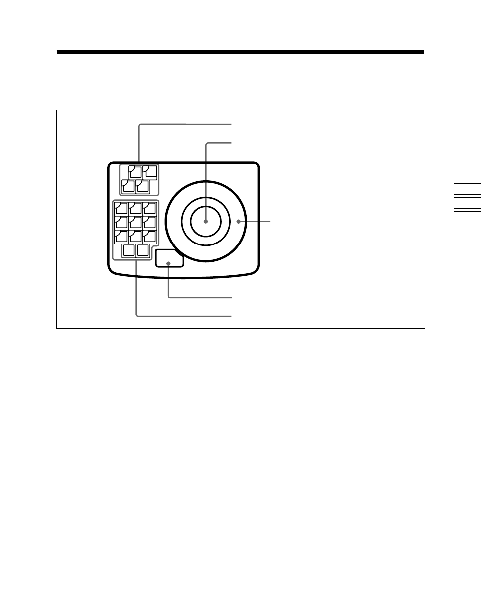
T ransformation Operation Section
The transformation operation section is
used for three-dimensional image
manipulation and cursor movement on
menu screens.
1 Function allocation section
2 Trackball
RUN
CURSR
CTRL
TRGTSRCE
ASP
LOC
LOC
SKEW
SIZE
XYZ
PERS
AXIS
ORTHG
ROT
LOC
XYZ
VELO
CTR
HOLD
3 Z-ring
SEL/FINE
2 Location and Function of Parts
4 SEL/FINE button
5 Transformation mode selection section
Transformation Operation Section
1 Function allocation section
Press any one of these buttons, turning it
on, to allocate the trackball 2 and Z-ring
3 as follows.
RUN CTRL (control) button: Allocates
CURSR (cursor) button: Allocates the
trackball to cursor movement on the
menu screens.
1)
This also allocates the Z-ring to adjust
the parameter at the cursor position.
the trackball and Z-ring to effect
execution.
SRCE (source) button: Allocates the
trackball and Z-ring to transformation
operation in the source coordinate
frame, that is, the coordinates based
on the video image itself.
1)
TRGT (target) button: Allocates the
2 Trackball
Depending on the state of the buttons in
the function allocation section 1,
trackball operation can be allocated to
effect execution, x- and y-axis movement
in transformation operations, or cursor
movement on the menu screens.
trackball and Z-ring to transformation
operation in the target coordinate
frame, that is, the coordinates based
on the output video space on the main
.................................................................................................................................................................................................................................................
monitor.
1) The rate of movement of image or cursor can be
varied in the TRACK BALL menu (page 10-10).
1)
Chapter 2 Location and Function of Parts
2-3

Transformation Operation Section
3 Z-ring
Depending on the state of the buttons in
the function allocation section 1, Z-ring
operation can be allocated to effect
execution, z-axis movement in
transformation operations, or to
adjustment of the parameter at the cursor
position.
controls the skew of the image, and
the Z-ring controls the aspect ratio.
When the SRCE button is lit, pressing
this button while holding down the
SHIFT button in the keyframe
operation section displays the X, Y,
and RATE parameters in the threedimensional parameter display section
of the menu screen. You can then
4 SEL/FINE (select/fine) button
The function of this button depends on the
2 Location and Function of Parts
selection made in the function allocation
section, as follows.
• When the CURSR button is lit, the SEL/
FINE button selects the item at the cursor
position, or toggles a function on or off.
When the cursor is indicating a parameter
value, pressing the SEL/FINE button
enables parameter input from the
numeric keypad.
• When the RUN CTRL, SRCE or TRGT
button is lit, holding down the SEL/FINE
button changes the effect of the trackball
or Z-ring to a fine adjustment.
1)
2)
change the image sizes in the x- and ydirections separately by using the
trackball, and adjust the aspect ratio
using the Z-ring.
When the TRGT button is lit, the
trackball and Z-ring vary the
perspective of the image.
2)
LOC (location) SIZE button: The Z-ring
changes the size of the image, and the
trackball moves the image in the xand y-directions.
LOC (location) XYZ button: The
trackball moves the image in the xand y-directions and the Z-ring moves
the image in the z-direction.
ORTHG (orthogonal) button: When
5 Transformation mode selection
section
When either of the SRCE and TRGT
buttons in the function allocation section
1 is lit, the buttons in this section
determine the nature of the transformation
carried out in the corresponding set of
coordinates.
ASP/SKEW/PERS (aspect/skew/
this button is lit, the image moves only
in the one of the x- and y-directions in
which the trackball is moved more. In
other words, this button can be used
for movement in the x- or y-direction
only.
When this button is off, the movement
of the image directly reflects the
movement of the trackball.
perspective) button: When the
SRCE button is lit, the trackball
.................................................................................................................................................................................................................................................
1) In this manual, the operation of pressing the SEL/
FINE button with the cursor on a particular item
is referred to as “clicking” on that item. Equally,
if the mouse is used to place the cursor on an
item, pressing and releasing a mouse button once
is also referred to as “clicking” on the item.
2) The rate of fineness or the function of the buttons
can be varied in the TRACK BALL menu (page
10-10).
2-4
Chapter 2 Location and Function of Parts

AXIS LOC (location) button: When this
button is lit, the axis of rotation of the
image is moved, in the x- and ydirections by the trackball, and in the
z-direction by the Z-ring.
ROT (rotation) button: The trackball
rotates the image about the x- and yaxes, and the Z-ring about the z-axis.
Pressing this button while holding
down the SHIFT button in the
keyframe operation section changes
the three-dimensional parameter
display section of the menu screen to
the TRGT SPIN display or SRCE
SPIN display according to the setting
of the function allocation section.
This enables you to use the spin
function.
X, Y, Z buttons: Use these buttons to
restrict the axes affected by movement
of the trackball and Z-ring.
Additionally, when one of these
buttons is lit, the numeric keypad can
be used to input coordinate data for
that axis.
CTR (center) button: Pressing this
button changes the current data values
for the trackball or Z-ring positions to
closest system-specified values (i.e.
provides a detent function).
Immediately pressing this button once
more reverts to the system default
1)
values.
VELO (velocity) HOLD button: If you
hold down this button, then move the
trackball or Z-ring, the movement
continue when you release the
2 Location and Function of Parts
trackball or Z-ring as long as you hold
down the button.
2)
.................................................................................................................................................................................................................................................
1) Using the spin function (page 3-28) in place of the
ROT button enables you to specify the number of
rotations when creating an effect.
2) The rate of movement can be varied in the
TRACK BALL menu (page 10-10).
Chapter 2 Location and Function of Parts
2-5
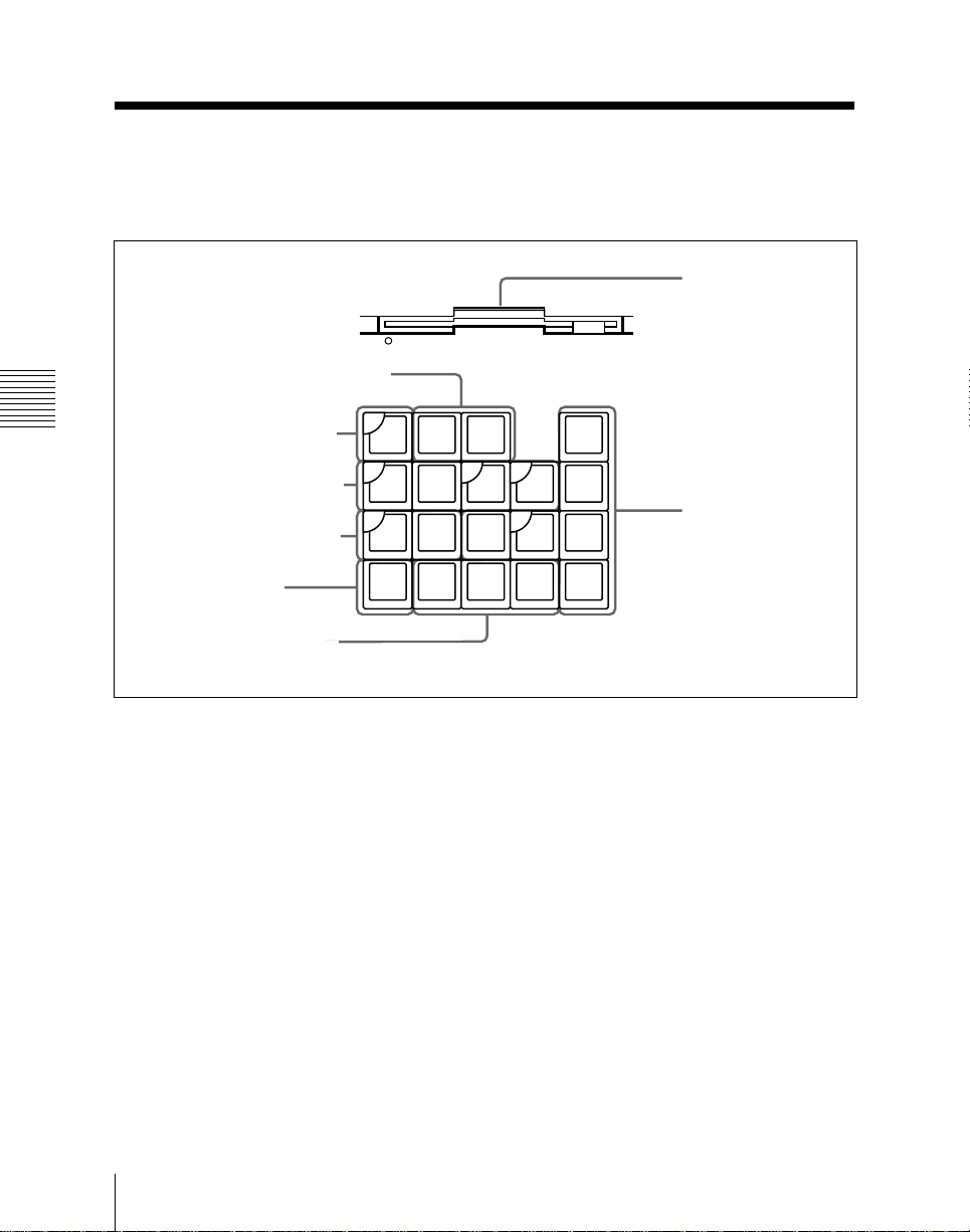
Keyframe Operation Section
The keyframe operation section is used for
creating, editing and executing keyframe
effects.
1 Effect store and recall section
8 Floppy disk drive
2 Location and Function of Parts
2 KF EDIT ENABL button
3 Effect execution section
4 Duration setting section
5 SHIFT button
6 Keyframe shift section
1 Effect store and recall section
RECAL EFF (recall effect) button:
Pressing this button then entering a
register number recalls the effect
stored in that register.
Entering a period “.” in place of the
number selects the next vacant register
after the currently recalled register.
Pressing this button then entering 0
returns to the state before recalling the
current effect, that is, to the state
before carrying out the edit.
KF
RECAL
EDIT
ENABL
RUN REW REVS
CNST
DUR
SHIFT
STORE
EFF
EFF
KF
DUR
DEL
EFF
PREVKFNEXT
STP
NEXT
KF
MOD
ALL
TC
GOTO
KF
KF
Keyframe operation section
STORE EFF (effect) button: Pressing
CLR
WORK
BUFF
UNDEL
UNDO
7 Keyframe editing
MOD
BEFR
INSRT
section
this button then entering a register
number saves a keyframe effect in the
corresponding register.
Again, entering a period “.” in place of
the number selects the next vacant
register after the currently recalled
register.
2-6
Chapter 2 Location and Function of Parts

2 KF (keyframe) EDIT ENABL
(enable) button
When this button is lit, the system is in
edit mode; that is, keyframes can be
created and edited. During effect
execution, however, creating and editing is
inhibited, regardless of the state of this
button.
When this button is off, the BEFR/INSRT,
MOD, DEL, UNDEL/UNDO, MOD ALL
and KF/DUR EFF buttons are disabled.
3 Effect execution section
RUN button: Pressing this button
executes a keyframe effect from the
current position to the last keyframe.
Pressing the button while the effect is
being executed pauses the effect, and
pressing it a third time resumes
execution.
If the current position is the last
keyframe, the system returns to the
initial keyframe and executes the
whole effect.
While the effect is being executed, this
button lights green.
REW (rewind) button: This rewinds the
currently recalled effect to the initial
keyframe, unless the REVS button is
lit, in which case it winds forward to
the last keyframe.
REVS (reverse) button: When this
button is lit, you can execute the effect
in the reverse direction, using the
RUN button.
STP (stop) NEXT KF (keyframe)
button: When this button is lit,
pressing the RUN button executes the
effect from the current position to the
next keyframe.
4 Duration setting section
CNST DUR (constant duration) button:
When this button is lit, inserting a
keyframe or deleting a keyframe does
not change the total duration of the
effect. Also, inserting or deleting a
keyframe does not change the position
on the time axis of any other
keyframes.
KF/DUR EFF(keyframe/effect duration)
button: Press this button on its own
to enter the total effect duration from
the numeric keypad.
Press this button while holding down
the SHIFT button 5 to enter a
keyframe duration from the numeric
keypad.
5 SHIFT button
Holding down this button while pressing
one of the buttons with two function
indications written on it (for example
UNDEL and UNDO) carries out the upper
function (for example UNDEL).
2 Location and Function of Parts
Chapter 2 Location and Function of Parts
2-7

Keyframe Operation Section
6 Keyframe shift section
PREV KF (previous keyframe) button:
Moves to the keyframe immediately
before the position at which the effect
is currently stopped.
NEXT KF (next keyframe) button:
Moves to the keyframe immediately
after the position at which the effect is
currently stopped.
TC/GO TO KF (time code/go to
keyframe) button: Press this button
2 Location and Function of Parts
on its own to move to a keyframe
whose number you enter from the
numeric keypad. Press this button
while holding down the SHIFT button
5 to move to a position specified by
entering a time code from the numeric
keypad.
7 Keyframe editing section
CLR (clear) WORK BUFF (buffer)
button: Pressing this button once
clears only the three-dimensional
transformation parameters held in the
working keyframe buffer. Pressing it
immediately a second time clears the
remainder of the information held in
the working keyframe buffer, and
returns it to the initial state. You can
make the initial state in the setup
menu (see page 10-7).
The working keyframe buffer is an
area of memory which holds the
instantaneous state of the effect.
While the effect is positioned on a
keyframe, this corresponds to the
contents of the keyframe, and while
the effect is between keyframes, to a
result of interpolation.
Pressing this button while holding
down the SHIFT button 5 in the
keyframe operation section resets all
parameter values in the active window
displayed on the menu screen to their
default values.
UNDEL/UNDO (undelete/undo) button:
Pressing this button on its own returns
the working keyframe buffer to the
state before it was last overwritten.
To remove a keyframe inserted with
the BEFR/INS button, for example,
press this button before carrying out
any other operation.
This button affects operations with the
BEFR/INS, DEL, MOD, KF /DUR
EFF buttons.
Pressing this button while holding
down the SHIFT button 5 inserts the
last deleted keyframe at the position
where the effect is currently stopped.
DEL (delete) button: This deletes the
current keyframe. If the effect is
currently stopped between two
keyframes, this deletes the
immediately previous keyframe.
MOD (modify) ALL button: When
amending, deleting or copying
keyframes, you can specify the range
of keyframes to which the operation
applies.
For details of how to specify the
range of keyframes to which the
operation applies, see page 7-12.
2-8
Chapter 2 Location and Function of Parts

MOD (modify) button: Rewrites the
current keyframe to be the same as the
current state of the working keyframe
buffer. If the effect is currently
stopped between two keyframes, this
overwrites the immediately previous
keyframe.
BEFR/INSRT (before/insert) button:
Inserts the contents of the working
keyframe buffer as a new keyframe.
Pressing this button on its own inserts
the new keyframe after the current
keyframe, if the effect is currently
stopped on a keyframe.
Pressing this button while holding
down the SHIFT button 5 inserts the
new keyframe before the current
keyframe.
If the effect is stopped between
keyframes, the new keyframe is
inserted at the current position.
8 Floppy disk drive
This accepts a 3.5-inch floppy disk for
loading or saving the contents of registers.
It is also used when upgrading the system
to load new software from disk into the
flash memory.
The indicator below and to the left of the
floppy disk drive lights during a disk
access.
2 Location and Function of Parts
Chapter 2 Location and Function of Parts
2-9
 Loading...