

Sony HDR-TG5,HDR-TG5V,HDR-TG5VE,HDR-TG7VE,HDR-TG5E Service Manual
Revision History
Revision History
Sony EMCS Co.
SERVICE MANUAL
LEVEL 2
Link
SERVICE NOTE
MODEL INFORMATION TABLE
SPECIFICATIONS
FRAME SCHEMATIC DIAGRAM
BLOCK DIAGRAMS
DISASSEMBLY
PRINTED WIRING BOARDS
REPAIR PARTS LIST
SCHEMATIC DIAGRAMS
Link
HDR-TG5/TG5E/TG5V/TG5VE/TG7VE_L2
Ver. 1.0 2009.03
2009C0500-1
© 2009.3
Published by Kohda TEC9-852-682-31
US Model
Canadian Model
AEP Model
UK Model
E Model
Australian Model
Hong Kong Model
Chinese Model
Korea Model
Tourist Model
Japanese Model
The components identified by
mark 0 or dotted line with
mark 0 are critical for safety.
Replace only with part number specified.
Les composants identifiés par une
marque 0 sont critiques pour la
sécurité.
Ne les remplacer que par une pièce
portant le numéro spécifié.
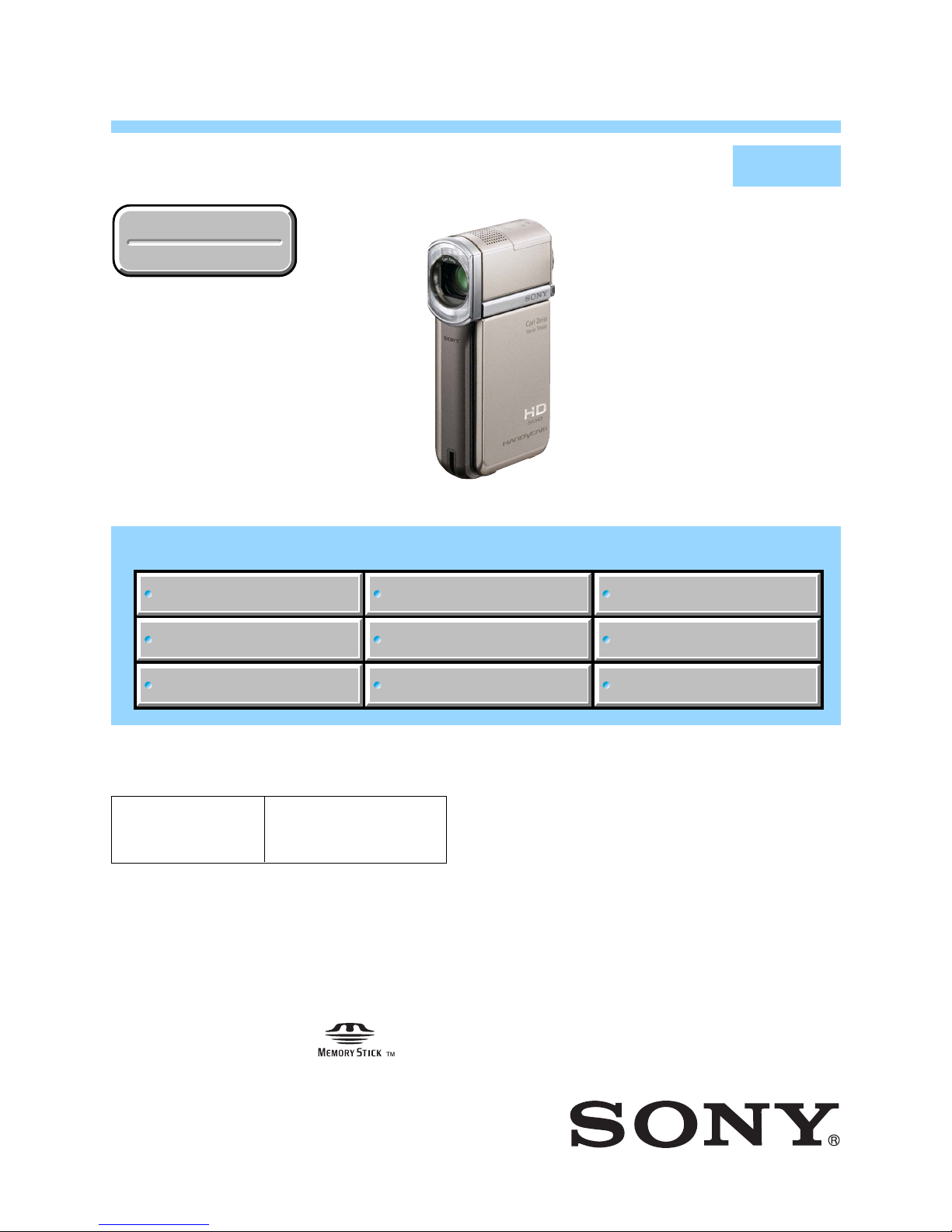
Photo: HDR-TG5V
DIGITAL HD VIDEO CAMERA RECORDER
• Precaution on Replacing the Internal Memory (MS7308)
• Precaution on Replacing the VC-561 Board
• Precaution on Replacing the Cabinet (L)
HDR-TG5/TG5E/TG5V/
TG5VE/TG7VE

— 2 —
HDR-TG5/TG5E/TG5V/TG5VE/TG7VE_L2
ENGLISH JAPANESE
ENGLISH JAPANESE
SPECIFICATIONS
These specifications are extracted from instruction
manual of HDR-TG5E/TG5VE/TG7VE.
System
Signal format: PAL color, CCIR standards HDTV
1080/50i specication
Movie recording format:
Video: HD: MPEG-4 AVC/H.264 AVCHD
format compatible
SD: MPEG-2 PS
Audio: Dolby Digital 2ch
Dolby Digital Stereo Creator
Photo le format
: DCF Ver.2.0 Compatible
: Exif Ver.2.21 Compatible
: MPF Baseline Compatible
Recording media (Movie/Photo)
Internal memory: 16 GB
“Memory Stick PRO Duo” media
HDR-TG5E:
When measuring media capacity, 1 GB equals
1 billion bytes, a portion of which is used for
data management.
HDR-TG5VE/TG7VE:
When measuring media capacity, 1 GB equals
1 billion bytes, a portion of which is used for
system management and/or application les.
e capacity used for this purpose is
approximately 1.24 GB.
Image device: 3.6 mm (1/5 type) CMOS sensor
Recording pixels (photo, 4:3):
Max. 4.0 mega (2 304
× 1 728) pixels
*
Gross: Approx. 2 360 000 pixels
Eective (movie, 16:9):
Approx. 1 430 000 pixels
Eective (photo, 16:9):
Approx. 1 490 000 pixels
Eective (photo, 4:3):
Approx. 1 990 000 pixels
Lens:
Carl Zeiss Vario-Tessar
10
× (Optical), 20 ×, 120 × (Digital)
F1.8 ~ 2.3
Focal length:
f=3.2 ~ 32.0 mm (5/32 ~ 1 5/16 in.)
When converted to a 35 mm still camera
For movies
**
: 43 ~ 507 mm (1 3/4 ~ 20 in.)
(16:9)
For photos: 38 ~ 380 mm (1 1/2 ~ 15 in.) (4:3)
Color temperature: [AUTO], [ONE PUSH],
[INDOOR] (3 200 K), [OUTDOOR] (5 800
K)
Minimum illumination
5 lx (lux) ([AUTO SLW SHUTTR] is set to [ON],
shutter speed 1/25 second)
*
e unique pixel array of Sony’s ClearVid
and the image processing system
(BIONZ) allow still image resolution
equivalent to the sizes described.
**
e focal length gures are actual gures
resulting from wide angle pixel readout.
Input/Output connectors
A/V Remote Connector: Component/video and
audio output jack
LCD screen
Picture: 6.7 cm (2.7 type, aspect ratio 16:9)
Tot al numb er of pixels: 211 200 (960
× 220)
General
Power requirements: DC 6.8 V/7.2 V (battery
pack) DC 8.4 V (AC Adaptor)
Ave ra ge power consumption: During camera
recording, using LCD screen at normal
brightness: HD: 3.1 W SD: 2.4 W
Operating temperature: 0
°C to 40 ° C (32 °F to
104 °F)
Storage tempe rature: –20
°C to + 60 ° C (-4 °F to
+140 °F)
Dimensions (approx.): 30
× 117 × 62 mm (1 3/16
× 4 5/8 × 2 1/2 in.) (w/h/d) including the
projecting parts
30
× 117 × 62 mm (1 3/16 × 4 5/8 × 2 1/2
in.) (w/h/d) including the projecting parts,
and the supplied rechargeable battery pack
attached
Mass (approx.)
HDR-TG5E:
220 g (7 oz) main unit only
270 g (9 oz) including the supplied
rechargeable battery pack
HDR-TG5VE/TG7VE:
230 g (8 oz) main unit only
280 g (9 oz) including the supplied
rechargeable battery pack
“Handycam” Station Cradle DCRA-C250
Input/Output connectors
A/V OUT jack: Component/
video and audio output jack
HDMI OUT jack: Type A (19-pin)
USB jack: mini-B
(HDR-TG7VE: output only)
Dedicated USB Terminal Adaptor
Input/Output connectors
USB jack: mini-B
(HDR-TG7VE: output only)
AC Adaptor AC-L200C/AC-L200D
Power requirements: AC 100 V - 240 V,
50 Hz/60 Hz
Current consumption: 0.35 A - 0.18 A
Power consumption: 18 W
Output voltage: DC 8.4 V
*
Operating temperature: 0 °C to 40 ° C (32 °F to
104 °F)
Storage temperature: –20
°C to + 60 ° C (-4 °F to
+140 °F)
Dimensions (approx.): 48 ×
29 × 81 mm (1 15/16
× 1 3/16 × 3 1/4 in.) (w/h/d) excluding the
projecting parts
Mass (approx.): 170 g (6.0 oz) excluding the
power cord (mains lead)
*
See the label on the AC Adaptor for other
specications.
Rechargeable battery pack NP-FH50
Maximum output voltage: DC 8.4 V
Output voltage: DC 6.8 V
Maximum charge voltage: DC 8.4 V
Maximum charge current: 1.75 A
Capacity
typical: 6.1 Wh (900 mAh)
minimum: 5.9 Wh (870 mAh)
Typ e: Li-ion
Design and specications of your camcorder and
accessories are subject to change without notice.
Manufactured under license from Dolby
Laboratories.
•

— 3 —
HDR-TG5/TG5E/TG5V/TG5VE/TG7VE_L2
ENGLISH JAPANESE
ENGLISH JAPANESE
SPECIFICATIONS
These specifications are extracted from instruction
manual of HDR-TG5/TG5V.
System
Signal format: NTSC color, EIA standards HDTV
1080/60i specication
Movie re cording format:
Video: HD: MPEG-4 AVC/H.264 AVCHD
format compatible
SD: MPEG-2 PS
Audio: Dolby Digital 2ch
Dolby Digital Stereo Creator
Photo le format
: DCF Ver.2.0 Compatible
: Exif Ver.2.21 Compatible
: MPF Baseline Compatible
Recording media (Movie/Photo)
Internal memory: 16 GB
“Memory Stick PRO Duo” media
HDR-TG5:
When measuring media capacity, 1 GB equals
1 billion bytes, a portion of which is used for
data management.
HDR-TG5V:
When measuring media capacity, 1 GB equals
1 billion bytes, a portion of which is used for
system management and/or application les.
e capacity used for this purpose is
approximately 1.24 GB.
Image device: 3.6 mm (1/5 type) CMOS sensor
Recording pixels (photo, 4:3):
Max. 4.0 mega (2 304
× 1 728) pixels
*
Gross: Approx. 2 360 000 pixels
Eective (movie, 16:9):
Approx. 1 430 000 pixels
Eective (photo, 16:9):
Approx. 1 490 000 pixels
Eective (photo, 4:3):
Approx. 1 990 000 pixels
Lens:
Carl Zeiss Vario-Tessar
10
× (Optical), 20 ×, 120 × (Digital)
F1.8 ~ 2.3
Focal length:
f=3.2 ~ 32.0 mm (5/32 ~ 1 5/16 in.)
When converted to a 35 mm still camera
For movies
**
: 43 ~ 507 mm (1 3/4 ~ 20 in.)
(16:9)
For photos: 38 ~ 380 mm (1 1/2 ~ 15 in.) (4:3)
Color temperature: [AUTO], [ONE PUSH],
[INDOOR] (3 200 K), [OUTDOOR] (5 800
K)
Minimum illumination
5 lx (lux) ([AUTO SLW SHUTTR] is set to [ON],
shutter speed 1/30 second)
*
e unique pixel array of Sony’s ClearVid
and the image processing system
(BIONZ) allow still image resolution
equivalent to the sizes described.
**
e focal length gures are actual gures
resulting from wide angle pixel readout.
Input/Output connectors
A/V Remote Connector: Component/video and
audio output jack
LCD screen
Picture: 6.7 cm (2.7 type, aspect ratio 16:9)
Tot al numb er of pixels: 211 200 (960
× 220)
General
Power requi rements: DC 6.8 V/7.2 V (battery
pack) DC 8.4 V (AC Adaptor)
Ave ra ge power consumption: During camera
recording, using LCD screen at normal
brightness: HD: 3.1 W SD: 2.4 W
Operating temperature: 0
°C to 40 ° C (32 °F to
104 °F)
Storage tempe rature: –20
°C to + 60 °C (-4 °F to
+140 °F)
Dimensions (approx.): 30
× 117 × 62 mm (1 3/16
× 4 5/8 × 2 1/2 in.) (w/h/d) including the
projecting parts
30
× 117 × 62 mm (1 3/16 × 4 5/8 × 2 1/2
in.) (w/h/d) including the projecting parts,
and the supplied rechargeable battery pack
attached
Mass (approx.)
HDR-TG5:
220 g (7 oz) main unit only
270 g (9 oz) including the supplied
rechargeable battery pack
HDR-TG5V:
230 g (8 oz) main unit only
280 g (9 oz) including the supplied
rechargeable battery pack
“Handycam” Station Cradle DCRA-C250
Input/Output connectors
A/V OUT jack: Component/
video and audio output jack
HDMI OUT jack: Type A (19-pin)
USB jack: mini-B
Dedicated USB Terminal Adaptor
Input/Output connectors
USB jack: mini-B
AC Adaptor AC-L200C/AC-L200D
Power requirements: AC 100 V - 240 V,
50 Hz/60 Hz
Current consumption: 0.35 A - 0.18 A
Power consumption: 18 W
Output voltage: DC 8.4 V
*
Operating temperature: 0 °C to 40 ° C (32 °F to
104 °F)
Storage tempe rature: –20
°C to + 60 °C (-4 °F to
+140 °F)
Dimensions (approx.): 48
× 29 × 81 mm (1 15/16
× 1 3/16 × 3 1/4 in.) (w/h/d) excluding the
projecting parts
Mass (approx.): 170 g (6.0 oz) excluding the
power cord (mains lead)
*
See the label on the AC Adaptor for other
specications.
Rechargeable battery pack NP-FH50
Maximum output voltage: DC 8.4 V
Output voltage: DC 6.8 V
Maximum charge voltage: DC 8.4 V
Maximum charge current: 1.75 A
Capacity
typical: 6.1 Wh (900 mAh)
minimum: 5.9 Wh (870 mAh)
Typ e: Li-ion
Design and specications of your camcorder and
accessories are subject to change without notice.
Manufactured under license from Dolby
Laboratories.
•
— 4 —
ENGLISH JAPANESE
ENGLISH JAPANESE
HDR-TG5/TG5E/TG5V/TG5VE/TG7VE_L2
概略仕様
システム
信号方式:
NTSC
カラー、
EIA
標準方式
ビデオ記録方式
映像:
HD
画質:
MPEG-4 AVC/H.264
AVCHD
規格準拠
SD
画質:
MPEG-2 PS
音声:
Dolby Digital 2ch
ドルビーデジタルステレオクリエーター搭載
静止画ファイルフォーマット
:
DCF Ver2.0
準拠
:
Exif Ver2.21
準拠
:
MPF Baseline
準拠
記録メディア(動画・静止画)
内蔵メモリー
16GB
PRO
容量は、1GBを10億バイトで計算した場合の数
値です。
また管理用ファイル、アプリケーションファイ
ルなどを含むため、実際に使用できる容量は減
少します。これに使用される容量は約
1.24GB
で
す。
撮像素子:
3.6 mm(1/5型)CMOS
センサー
記録画素数:静止画時
最大
400
万画素相当
*
(
2304×1728)(4:3
時)
総画素数:約
236
万画素
動画時有効画素数(
16:9
):約
143
万画素
静止画時有効画素数(
16:9
):約
149
万画素
静止画時有効画素数(
4:3
):約
199
万画素
ズームレンズ:カール ツァイス バリオテッサー
10
倍(光学)、20倍、
120
倍(デジタル)
F1.8〜2.3
f=3.2
〜
32.0 mm
35mm
カメラ換算では
動画撮影時
**
:
43〜507 mm(16:9
)
静止画撮影時:
38〜380 mm(4:3
)
]内屋[、]ュシップンワ[、]トーオ[:え換り切度温色
(
3 200 K
(]外屋[、)
5 800 K
)
最低被写体照度:
5 lx
ッャシロストーオ[()スクル(
ドーピスータッャシ、]入[]タ
1/30
秒)
*
ソニー独自のクリアビッド画素配列と画像処
理システム
BIONZ
により、静止画は表記の記
録サイズを実現しています。
**
広角画素読み出しによる実動作値
入/出力端子
A/V
リモート端子:コンポーネント、映像音声出力兼
用端子
液晶画面
画面サイズ:
6.7 cm(2.7
型、アスペクト比16:9)
総ドット数:
211 200
ドット
横
960×縦220
電源部、その他
電源電圧:バッテリー端子入力
6.8 V/7.2 V
DC
端子入力
8.4 V
消費電力:液晶画面の明るさ標準:
HD:3.1 W
SD
:
2.4 W
動作温度:0℃〜40℃
保存温度:−
20℃〜+60
℃
外形寸法:
30×117×62 mm
)き行奥×さ高×幅()む含を部起突(
30×117×62 mm
(突起部を含む、付属バッテリー装着状態)
(幅×高さ×奥行き)
本体質量:
約
230 g
(本体のみ)
撮影時総質量:
約
280 g
(付属バッテリー含む。)
DCRA-C250
入/出力端子
A/V OUT
端子:コンポーネント、映像音声出力兼用
端子
HDMI OUT
端子:タイプA(19ピン)
USB
端子:
mini-B
専用
USB
端子アダプター
入
/
出力端子
USB
端子:
mini-B
AC
アダプター
AC-L200C/AC-L200D
電源:
AC 100 V - 240 V、50 Hz/60 Hz
消費電力:
18 W
定格出力:
DC 8.4 V
*
動作温度:0℃〜40℃
保存温度:−
20℃〜+60
℃
外形寸法:約
48×29×81 mm
(最大突起部をのぞ
)き行奥×さ高×幅()く
質量:約
170 g
(本体のみ)
*
その他の仕様についてはACアダプターのラベルを
ご覧ください。
リチャージャブルバッテリーパック
NP-FH50
最大電圧:
DC 8.4 V
公称電圧:
DC 6.8 V
容量:
公称容量:
6.1Wh(900mAh
)
定格(最小)容量:
5.9Wh(870mAh
)
使用電池:
Li-ion
本機やアクセサリーの仕様および外観は、改良のため
予告なく変更することがありますが、ご了承ください。
•
ドルビーラボラトリーズからの実施権に基づ
き製造されています。
— 5 —
HDR-TG5/TG5E/TG5V/TG5VE/TG7VE_L2
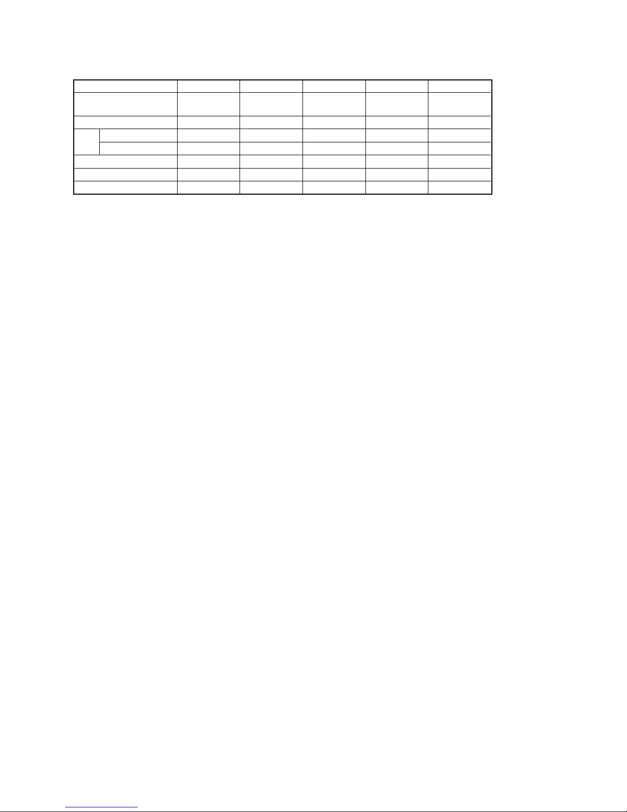
Model information table
•Abbreviation
AR : Argentine model
AUS: Australian model
BR : Brazilian model
CH : Chinese model
CND : Canadian model
EE : East European model
HK : Hong Kong model
J: Japanese model
JE : Tourist model
KR : Korea model
NE : North European model
TH : Thai model
Model HDR-TG5 HDR-TG5E HDR-TG5V HDR-TG5VE HDR-TG7VE
Destination E, KR, JE
E, HK,
US, CND, J AEP, AUS AEP, UK
CH, JE
Color system NTSC PAL NTSC PAL PAL
Data
CAM → PC aaaaa
copy
PC → CAM aaaa ×
GPS ××aaa
GM-055 assy ××aaa
FP-1084 flexible board ××aaa
— 6 —
HDR-TG5/TG5E/TG5V/TG5VE/TG7VE_L2
ENGLISH JAPANESE
ENGLISH JAPANESE
SAFETY-RELATED COMPONENT WARNING!!
COMPONENTS IDENTIFIED BY MARK 0 OR DOTTED LINE WITH
MARK 0 ON THE SCHEMATIC DIAGRAMS AND IN THE PARTS
LIST ARE CRITICAL TO SAFE OPERATION. REPLACE THESE
COMPONENTS WITH SONY PARTS WHOSE PART NUMBERS
APPEAR AS SHOWN IN THIS MANUAL OR IN SUPPLEMENTS
PUBLISHED BY SONY.
1. Check the area of your repair for unsoldered or poorly-soldered
connections. Check the entire board surface for solder splashes
and bridges.
2. Check the interboard wiring to ensure that no wires are
“pinched” or contact high-wattage resistors.
3. Look for unauthorized replacement parts, particularly
transistors, that were installed during a previous repair. Point
them out to the customer and recommend their replacement.
4. Look for parts which, through functioning, show obvious signs
of deterioration. Point them out to the customer and
recommend their replacement.
5. Check the B+ voltage to see it is at the values specified.
6. Flexible Circuit Board Repairing
•Keep the temperature of the soldering iron around 270˚C
during repairing.
• Do not touch the soldering iron on the same conductor of the
circuit board (within 3 times).
• Be careful not to apply force on the conductor when soldering
or unsoldering.
SAFETY CHECK-OUT
After correcting the original service problem, perform the following
safety checks before releasing the set to the customer.
ATTENTION AU COMPOSANT AYANT RAPPORT
À LA SÉCURITÉ!
LES COMPOSANTS IDENTIFÉS PAR UNE MARQUE 0 SUR LES
DIAGRAMMES SCHÉMATIQUES ET LA LISTE DES PIÈCES SONT
CRITIQUES POUR LA SÉCURITÉ DE FONCTIONNEMENT. NE
REMPLACER CES COMPOSANTS QUE PAR DES PIÈSES SONY
DONT LES NUMÉROS SONT DONNÉS DANS CE MANUEL OU
DANS LES SUPPÉMENTS PUBLIÉS PAR SONY.
Unleaded solder
Boards requiring use of unleaded solder are printed with the leadfree mark (LF) indicating the solder contains no lead.
(Caution: Some printed circuit boards may not come printed with
the lead free mark due to their particular size.)
: LEAD FREE MARK
Unleaded solder has the following characteristics.
• Unleaded solder melts at a temperature about 40°C higher than
ordinary solder.
Ordinary soldering irons can be used but the iron tip has to be
applied to the solder joint for a slightly longer time.
Soldering irons using a temperature regulator should be set to
about 350°C.
Caution: The printed pattern (copper foil) may peel away if the
heated tip is applied for too long, so be careful!
• Strong viscosity
Unleaded solder is more viscous (sticky, less prone to flow) than
ordinary solder so use caution not to let solder bridges occur such
as on IC pins, etc.
•Usable with ordinary solder
It is best to use only unleaded solder but unleaded solder may
also be added to ordinary solder.
CAUTION
Danger of explosion if battery is incorrectly replaced.
Replace only with the same or equivalent type.
Dispose of used batteries according to the instructions.
— 7 —
ENGLISH JAPANESE
ENGLISH JAPANESE
HDR-TG5/TG5E/TG5V/TG5VE/TG7VE_L2
1. 注意事項をお守りください。
サービスのとき特に注意を要する個所については,
キャビネット,シャーシ,部品などにラベルや捺印で
注意事項を表示しています。これらの注意書き及び取
扱説明書等の注意事項を必ずお守り下さい。
2. 指定部品のご使用を
セットの部品は難燃性や耐電圧など安全上の特性を
持ったものとなっています。従って交換部品は,使用
されていたものと同じ特性の部品を使用して下さい。
特に回路図,部品表に0印で指定されている安全上重要
な部品は必ず指定のものをご使用下さい。
3. 部品の取付けや配線の引きまわしはもとどおりに
安全上,チューブやテープなどの絶縁材料を使用した
り,プリント基板から浮かして取付けた部品がありま
す。また内部配線は引きまわしやクランパによって発
熱部品や高圧部品に接近しないよう配慮されています
ので,これらは必ずもとどおりにして下さい。
4. サービス後は安全点検を
サービスのために取外したネジ,部品,配線がもとど
おりになっているか,またサービスした個所の周辺を
劣化させてしまったところがないかなどを点検し,安
全性が確保されていることを確認して下さい。
5. チップ部品交換時の注意
• 取外した部品は再使用しないで下さい。
• タンタルコンデンサのマイナス側は熱に弱いため交
換時は注意して下さい。
サービス,点検時には次のことにご注意下さい。
6. フレキシブルプリント基板の取扱いについて
• コテ先温度を270℃前後にして行なって下さい。
• 同一パターンに何度もコテ先を当てないで下さい。
(3回以内)
• パターンに力が加わらないよう注意して下さい。
7. 無鉛半田について
無鉛半田を使用している基板には,無鉛(LeadFree)を意
味するレッドフリーマークがプリントされています。
(注意:基板サイズによっては,無鉛半田を使用して
いてもレッドフリーマークがプリントされて
いないものがあります)
:レッドフリーマーク
無鉛半田には,以下の特性があります。
• 融点が従来の半田よりも約40℃高い。
従来の半田こてをそのまま使用することは可能です
が,少し長めにこてを当てる必要があります。
温度調節機能のついた半田こてを使用する場合,約
350℃に設定して下さい。
注意: 半田こてを長く当てすぎると,基板のパター
ン(銅箔)がはがれてしまうことがあります
ので,注意して下さい。
• 粘性が強い
従来の半田よりも粘性が強いため,IC端子などが半田
ブリッジしないように注意して下さい。
• 従来の半田と混ぜて使用可能
無鉛半田には無鉛半田を追加するのが最適ですが,
従来の半田を追加しても構いません。
注意
電池の交換は,正しく行わないと破裂する恐れがあります。
電池を交換する場合には必ず同じ型名の電池又は同等品と交換
してください。
使用済み電池は,取扱指示に従って処分してください。
1-1
ENGLISH JAPANESE
ENGLISH JAPANESE
HDR-TG5/TG5E/TG5V/TG5VE/TG7VE_L2
1. SERVICE NOTE
1-1. POWER SUPPLY DURING REPAIRS
In this unit, about 10 seconds after power is supplied to the battery terminal using the regulated power supply (8.4 V), the power is shut off so
that the unit cannot operate.
These following method is available to prevent this.
Method:
Use the AC power adaptor (AC-L200C/L200D).
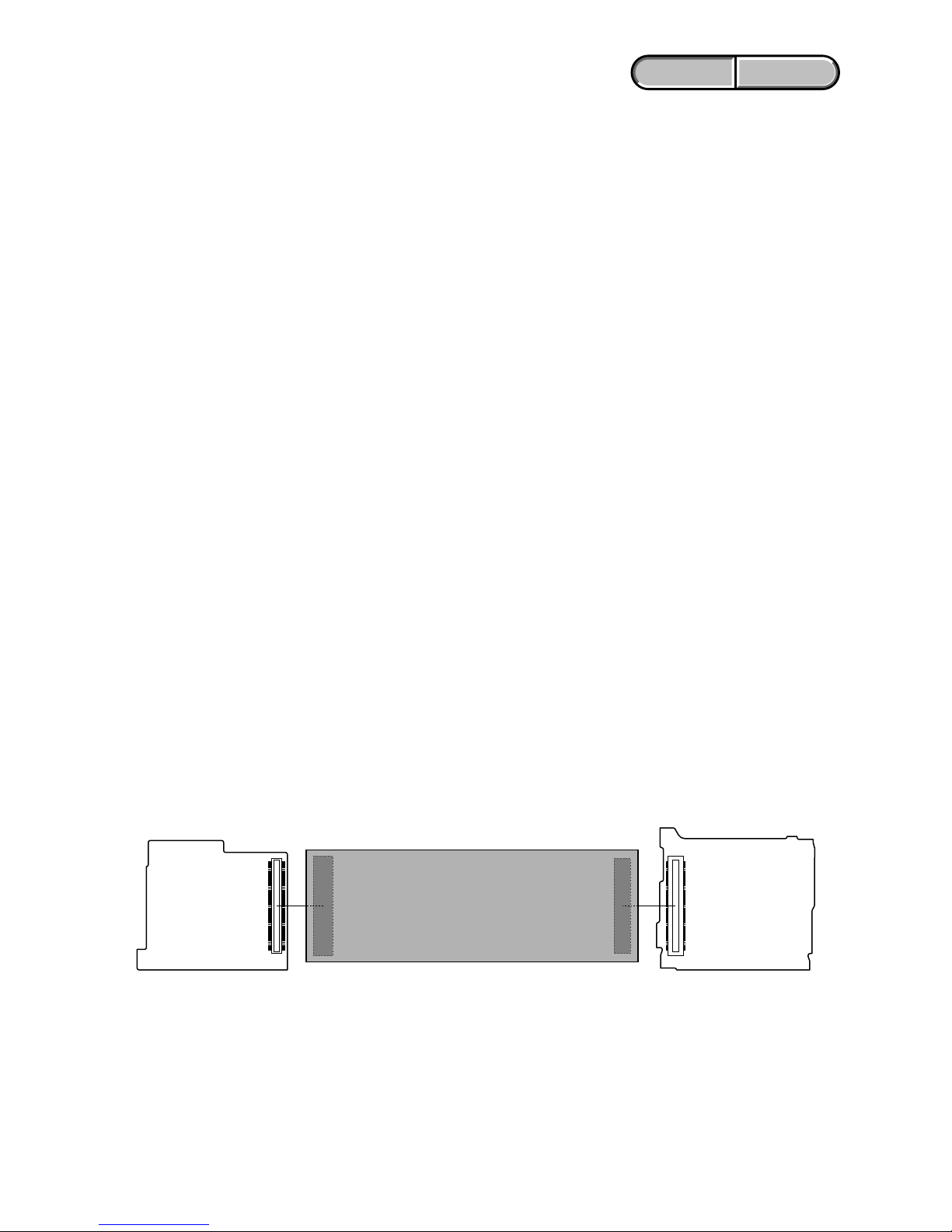
1-3. PRECAUTION ON REPLACING THE VC-561 BOARD
DESTINATION DATA
When you replace to the repairing board, the written destination data of repairing board also might be changed to original setting.
Start the Adjust Manual in the Adjust Station and execute the “DESTINATION DATA WRITE”.
RESTORE DATA
When you replace to the repairing board, get the data from the former one.
Start the Adjust Manual in the Adjust Station and perform “RESTORE DATA” to get the data.
The data getting for this model is as follows.
• USB SERIAL No.
USB SERIAL No.
The set is shipped with a unique ID (USB Serial No.) written in it.
This ID has not been written in a new board for service, and therefore it must be entered after the board replacement.
Start the Adjust Manual in the Adjust Station and execute the “USB SERIAL No. INPUT”.
1-2. PRECAUTION ON REPLACING THE INTERNAL MEMORY (MS7308)
When replacing the internal memory (MS7308 that has been inserted in the MS-423 board), start the Adjust Manual in the Adjust Station and
refer to the “INTERNAL MEMORY ADJUSTMENTS”.
TG5V/TG5VE/TG7VE Only:
Do not factory check the internal memory (MS7308 that has been inserted in the MS-423 board) in which Map Data is installed (TG5V/
TG5VE/TG7VE).
The map data is erased when the factory check is done.
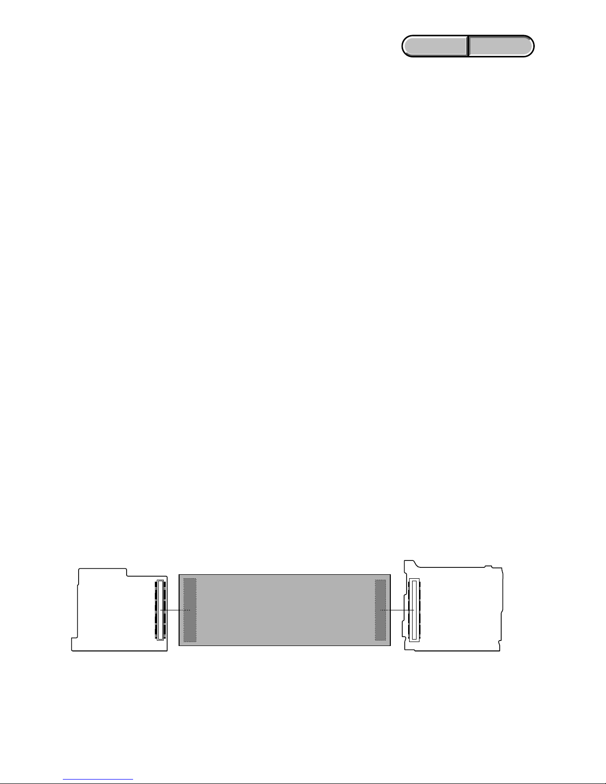
VC-561 BOARD (SIDE B)
Extension cable (120P)
J-6082-656-A
DD-312 BOARD (SIDE A)
CN1001
CN1101
1-4. USING SERVICE JIG
Connect the extension cable (J-6082-656-A) between CN1101 on the DD-312 board and CN1001 on the VC-561 board.
1-2
ENGLISH JAPANESE
ENGLISH JAPANESE
HDR-TG5/TG5E/TG5V/TG5VE/TG7VE_L2
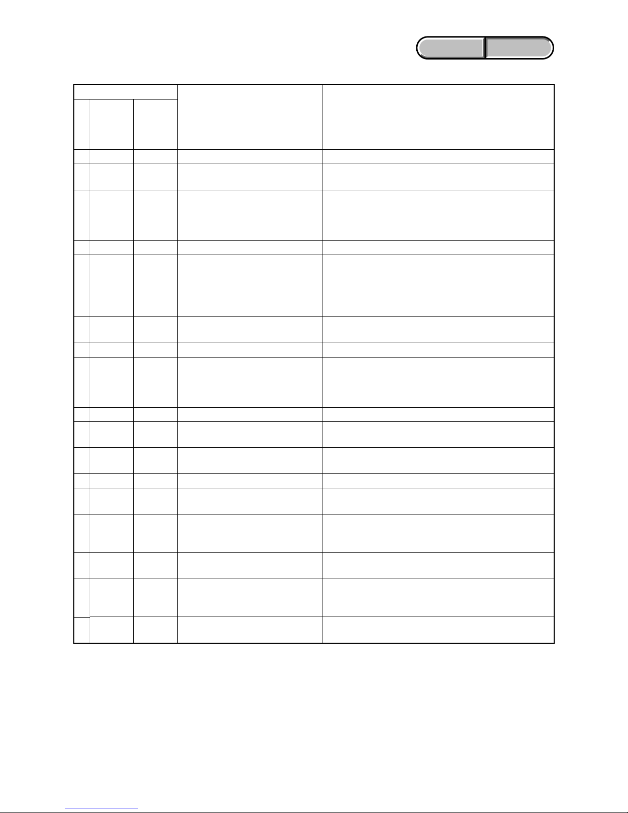
1-5. SELF-DIAGNOSIS FUNCTION
1-5-1. Self-diagnosis Function
When problems occur while the unit is operating, the self-diagnosis
function starts working, and displays on the LCD screen what to
do.
Details of the self-diagnosis functions are provided in the Instruction
manual.
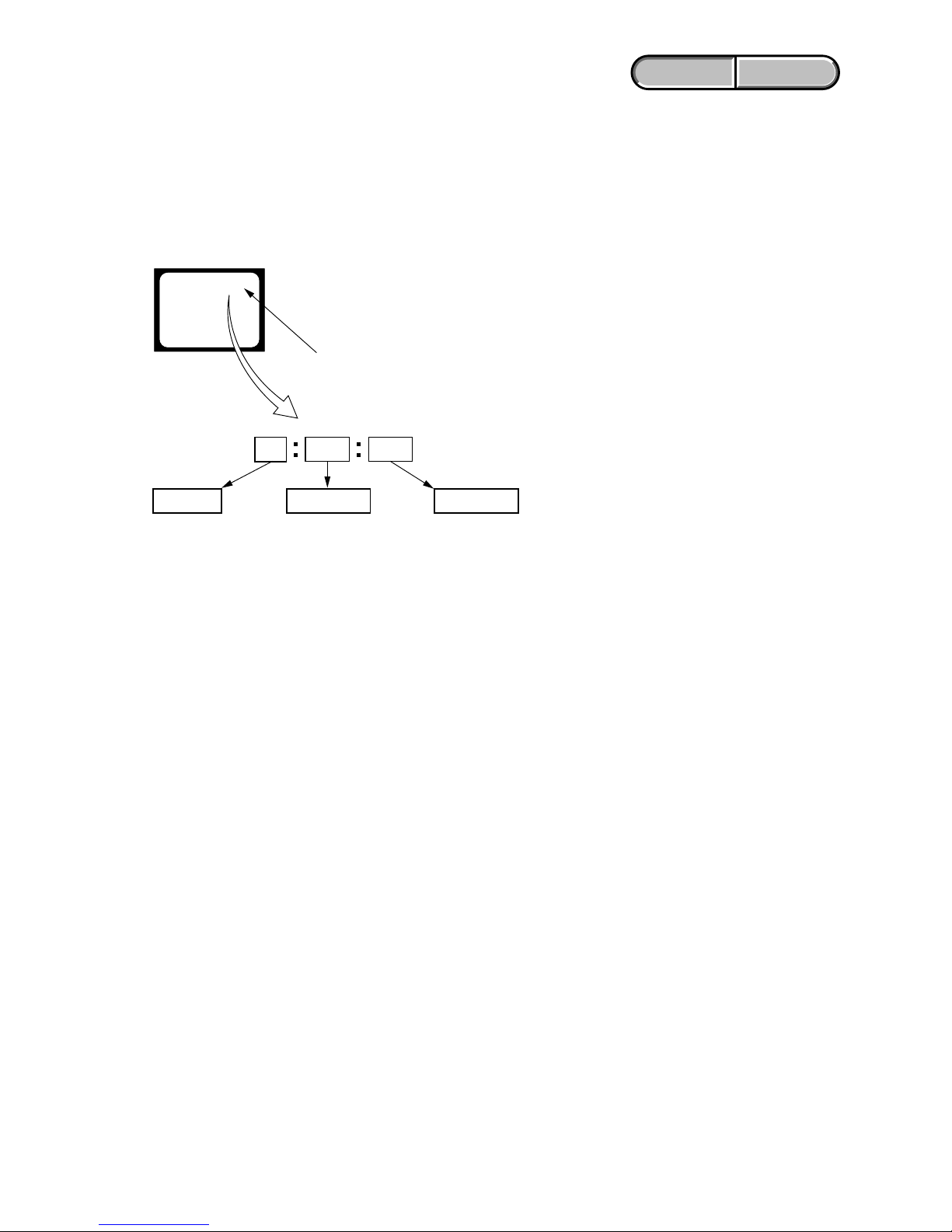
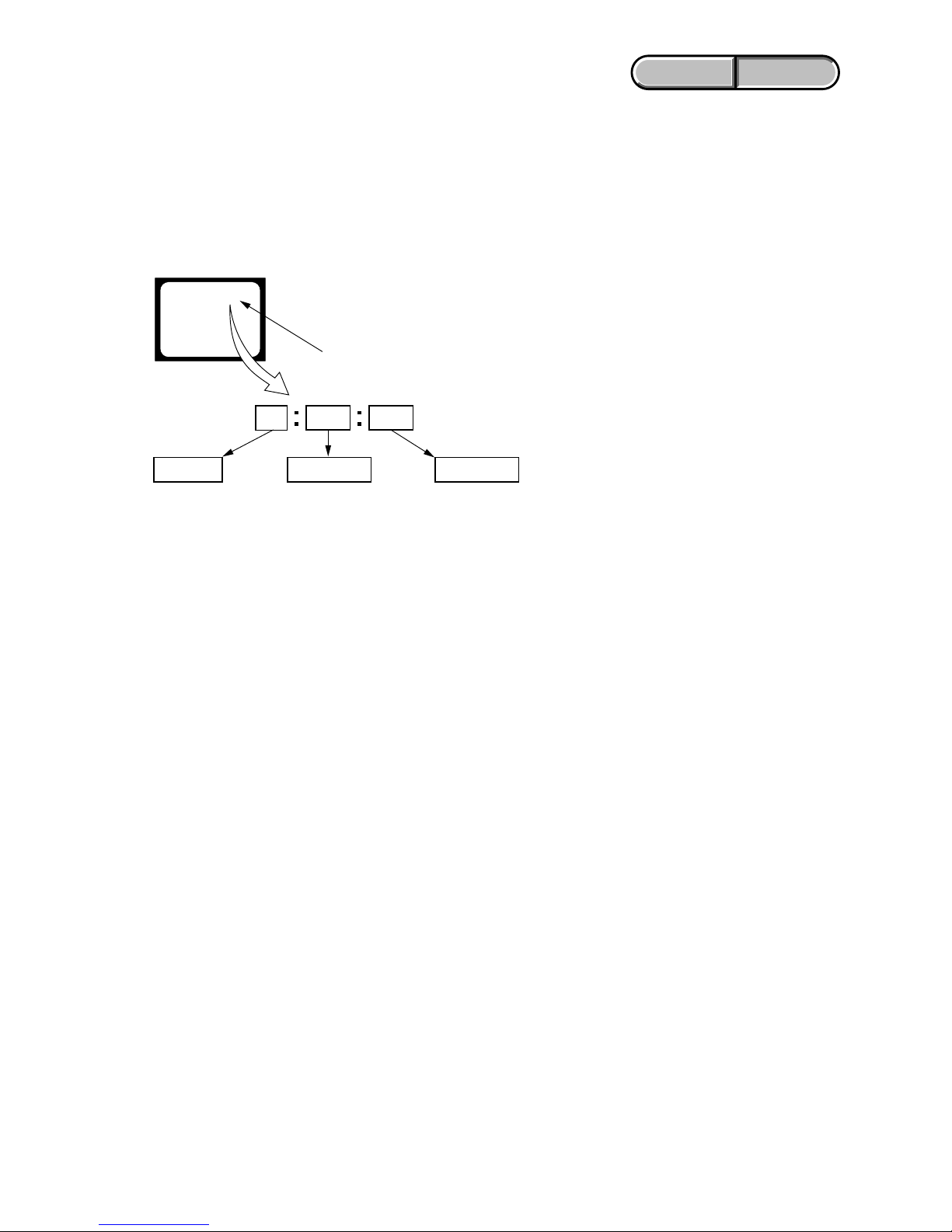
1-5-2. Self-diagnosis Display
When problems occur while the unit is operating, the counter of the
viewfinder or LCD screen shows a 4-digit display consisting of an
alphabet and numbers, which blinks at 3.2 Hz. This 5-character
display indicates the “repaired by:”, “block” in which the problem
occurred, and “detailed code” of the problem.
1 1
3 1C
Repaired by:
Refer to “1-5-3. Self-diagnosis Code Table”.
Indicates the appropriate
step to be taken.
E.g.
31 ....Reload the tape.
32 ....Turn on power again.
Block
Detailed Code
Blinks at 3.2 Hz
C : Corrected by customer
H : Corrected by dealer
E : Corrected by service
engineer
LCD screen
C : 3 1 : 1 1
1-3
ENGLISH JAPANESE
ENGLISH JAPANESE
HDR-TG5/TG5E/TG5V/TG5VE/TG7VE_L2
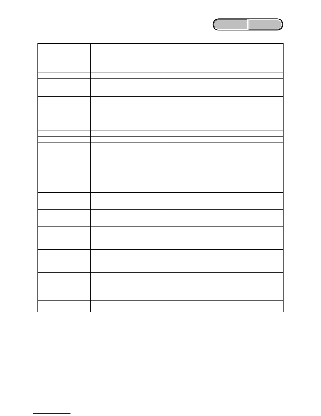
Correction
Use the InfoLITHIUM battery.
Change the battery pack or place it in a cool place.
Format the “Memory Stick Duo”.
Insert a new “Memory Stick Duo”.
Remove the power source.
Reconnect it again and operate your camcorder again.
Retry turn the power on by the power switch. If it does not
recover, check the focus MR sensor of lens block (pin 1, 2 of
CN1003 on the VC-561 board). If it is OK, check the focus
motor drive IC (IC5201 on the VC-561 board).
Make flash memory data correct value. (Note 1)
Inspect or replacement of the internal memory (MS7308)
Inspect the lens block zoom reset sensor (pin wf of CN1003 on
the VC-561 board) when zooming is performed when the zoom
lever is operated, and the zoom motor drive circuit (IC5203 on
the VC-561 board) when zooming is not performed.
Check both C : 32 : 60 and E : 61 : 10 of the self-diagnosis code.
Inspect PITCH/YAW angular velocity sensors (SE6601 on the
GY-016 board) peripheral circuits.
Inspect PITCH/YAW angular velocity sensors (SE6601 on the
GY-016 board) peripheral circuits.
Checking of flash unit or replacement of flash unit.
Inspect the flash memory (IC2101 on the VC-561 board).
Format the internal memory (MS7308).
Insert a new internal memory (MS7308). (Note 2)
Inspect the flash memory (IC2101 on the VC-561 board). If it is
OK, check the CPU (IC1701 on the VC-561 board).
TG5V/TG5VE/TG7VE:
Check whether the flexible board of the GPS module is broken,
and check whether it is inserted imperfectly. If there is no
problem the flexible board, inspect or replacement of the GPS
module.
TG5V/TG5VE/TG7VE:
Inspect or replacement of the internal memory (MS7308).
Symptom/State
Non-standard battery is used.
The battery pack temperature is high.
“Memory Stick Duo” is unformatted.
“Memory Stick Duo” is broken.
Access error
Difficult to adjust focus
(Cannot initialize focus)
Flash memory data are rewritten.
Drive fault
Zoom operations fault
(Cannot initialize zoom lens.)
The abnormalities in initialization of
the focus lens and the abnormalities in
initialization of the zoom lens occurred
simultaneously.
Handshake correction function does not
work well. (With PITCH angular
velocity sensor output stopped.)
Handshake correction function does not
work well. (With YAW angular velocity
sensor output stopped.)
Abnormality when flash is being
charged.
Fault of writing to or erasing the flash
memory
Internal memory is unformatted.
Internal memory is broken.
BGM data error
GPS hardware error
Map area mount error
1-5-3. Self-diagnosis Code Table
C
C
C
C
C
E
E
E
E
E
E
E
E
E
E
E
E
Block
Function
04
06
13
13
32
20
31
61
61
62
62
91
94
94
94
95
96
Detailed
Code
00
00
01
02
60
00
00
10
11
00
01
01
00
01
02
00
00
Self-diagnosis Code
Repaired by:
Note 1: Start the Adjust Manual in the Adjust Station and refer to the “DESTINATION DATA WRITE”.
Note 2: Start the Adjust Manual in the Adjust Station and refer to the “INTERNAL MEMORY ADJUSTMENTS”.
1-4
ENGLISH JAPANESE
ENGLISH JAPANESE
HDR-TG5/TG5E/TG5V/TG5VE/TG7VE_L2
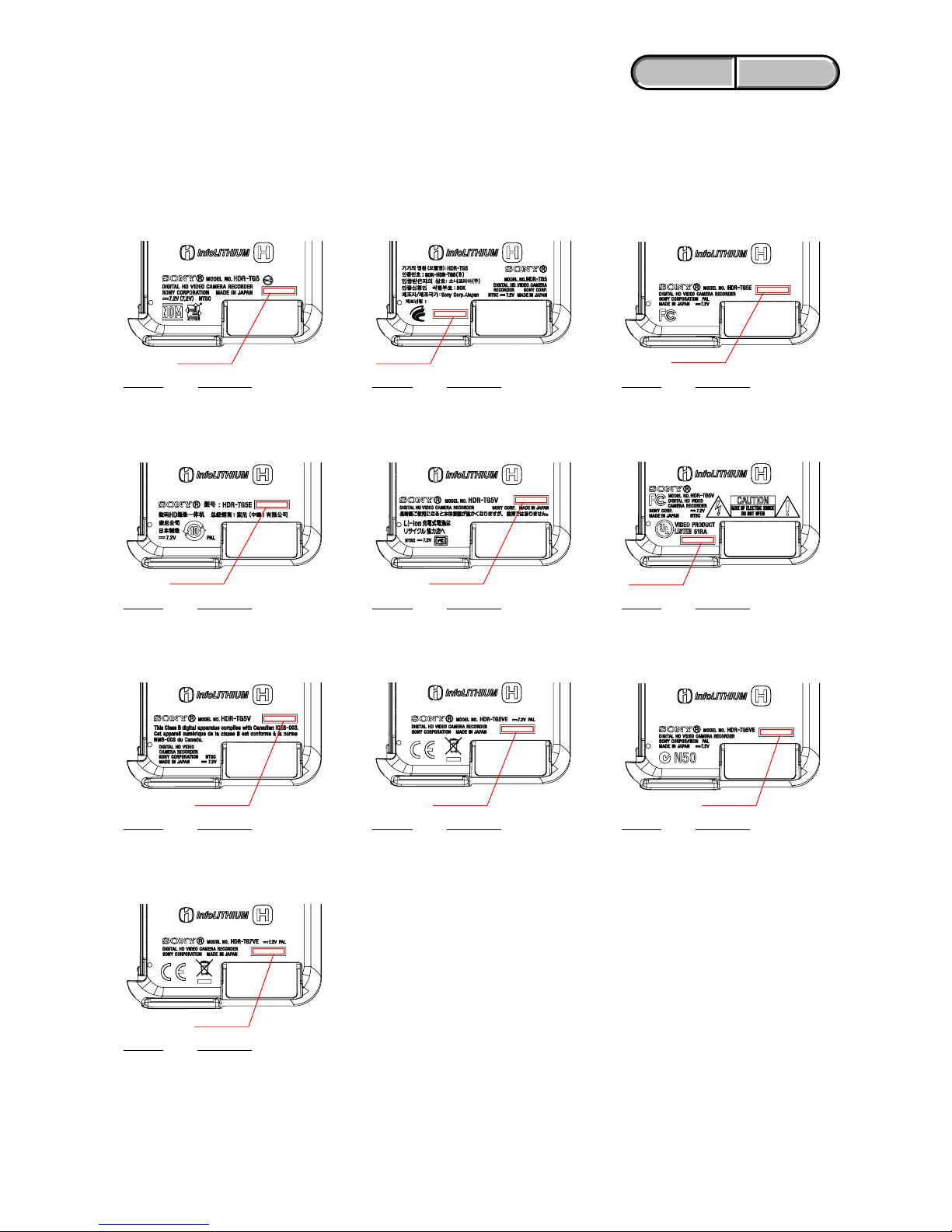
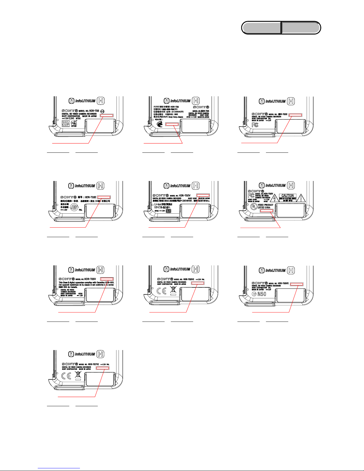
1-6-1. Precaution on ordering the Cabinet (L)
The model display adopts the laser printing method.
Therefore, the Cabinet (L) for replacement differs depending on
the destination.
As similar displays are provided, choose the suitable one for order.
Note: After replacing the Cabinet (L), the serial number for it will
be changed to the one exclusive for service use.
Inform a customer of the serial number change and change
the serial number in the repair data.
1-6. PRECAUTION ON REPLACING THE CABINET (L)
HDR-TG5 (E, JE)
A-1726-248-A CABINET (L (TG5-E23)),
SERVICE
Serial No.
Serial No.
Serial No.
Serial No.
Serial No.
Serial No. Serial No.
Serial No. Serial No.
HDR-TG5 (KR)
A-1726-249-A CABINET (L (TG5-KR2)),
SERVICE
HDR-TG5E (E, HK, JE)
A-1726-251-A CABINET (L (TG5-E34)),
SERVICE
HDR-TG5E (CH)
A-1726-252-A CABINET (L (TG5-CN2)),
SERVICE
HDR-TG5V (J)
A-1726-242-A CABINET (L (TG5-J1)),
SERVICE
HDR-TG5V (US)
A-1726-244-A CABINET (L (TG5-U2)),
SERVICE
HDR-TG5V (CND)
A-1726-245-A CABINET (L (TG5-CA2)),
SERVICE
HDR-TG5VE (AEP)
A-1726-246-A CABINET (L (TG5-CEN)),
SERVICE
HDR-TG5VE (AUS)
A-1726-247-A CABINET (L (TG5-AU2)),
SERVICE
Part No. Description
Part No. Description
Part No. Description
Part No. Description Part No. Description
Part No. Description
Part No. Description Part No. Description Part No. Description
HDR-TG7VE (AEP, UK)
A-1726-253-A CABINET (L (TG7-CEH)),
SERVICE
Part No. Description
Serial No.
1-5
ENGLISH JAPANESE
ENGLISH JAPANESE
HDR-TG5/TG5E/TG5V/TG5VE/TG7VE_L2
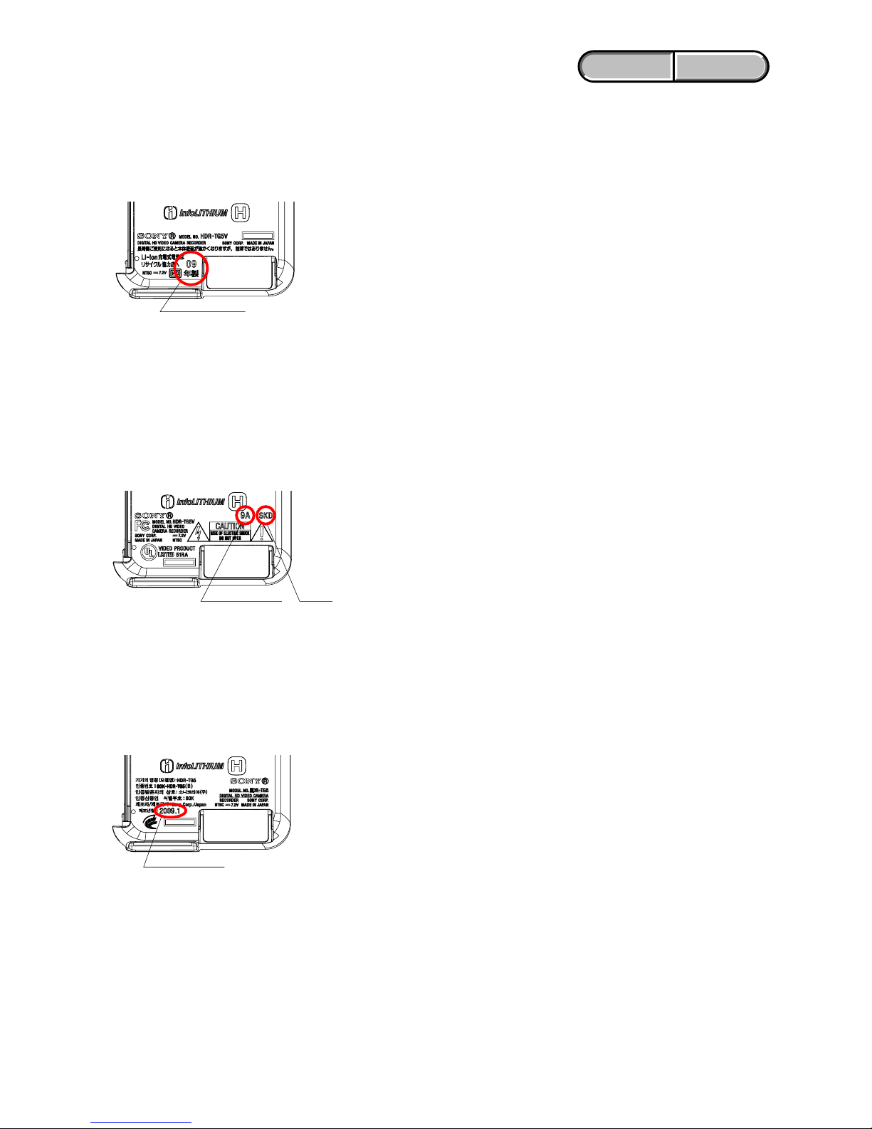
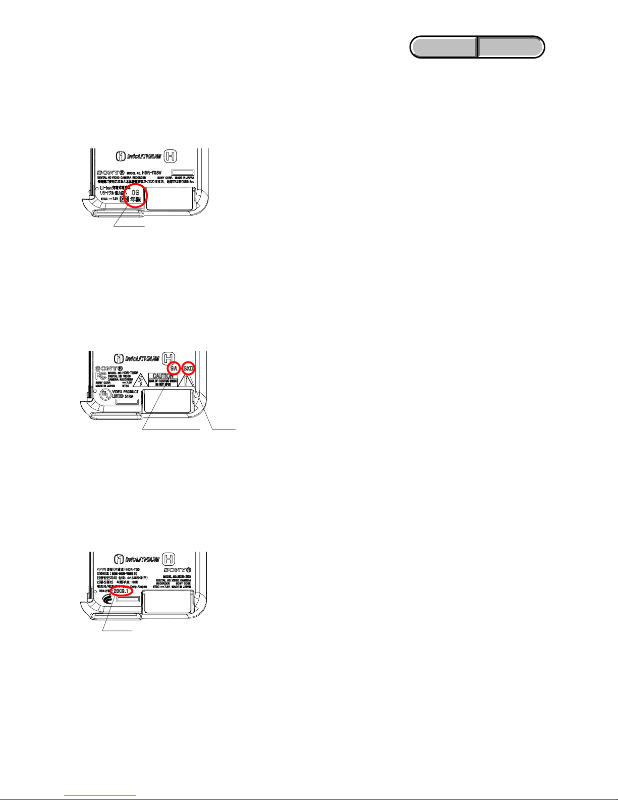
1-6-2. Precaution on Replacing the Cabinet (L) for J Model
The year of manufacture on the labels should be the same as the previous Cabinet (L) (circled portions shown on the below).
Example: For the figure below, attach the “Made of 09 years” label.
* The replacement label and “inset (how to affix)” are supplied together with Cabinet (L) for service.
1-6-3. Precaution on Replacing the Cabinet (L) for US Model
The date of manufacture and the manufacturer on the labels should be the same as the previous Cabinet (L) (circled portions shown on the
below).
Example: For the figure below, attach the “9A” and “SKD” labels.
* The replacement labels and “inset (how to affix)” are supplied together with Cabinet (L) for service.
1-6-4. Precaution on Replacing the Cabinet (L) for KR Model
The date of manufacture on the labels should be the same as the previous Cabinet (L) (circled portions shown on the below).
Example: For the figure below, attach the “2009.1” label.
* The replacement label and “inset (how to affix)” are supplied together with Cabinet (L) for service.
* Affix the label
*
Manufacturing year
HDR-TG5V (J)
* Affix the label
*
Manufacturing year
*
Factory
HDR-TG5V (US)
* Affix the label
HDR-TG5 (KR)
*
Manufacturing year
1-6
ENGLISH JAPANESE
ENGLISH JAPANESE
HDR-TG5/TG5E/TG5V/TG5VE/TG7VE_L2
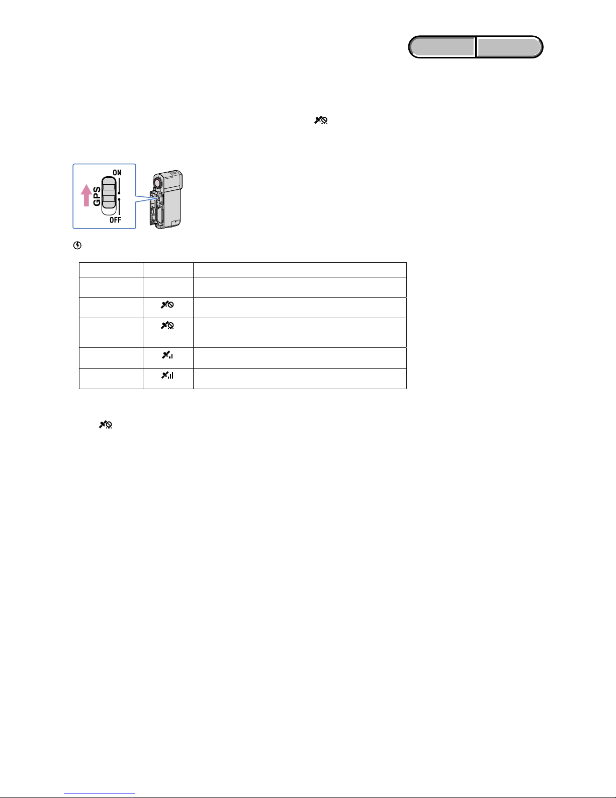
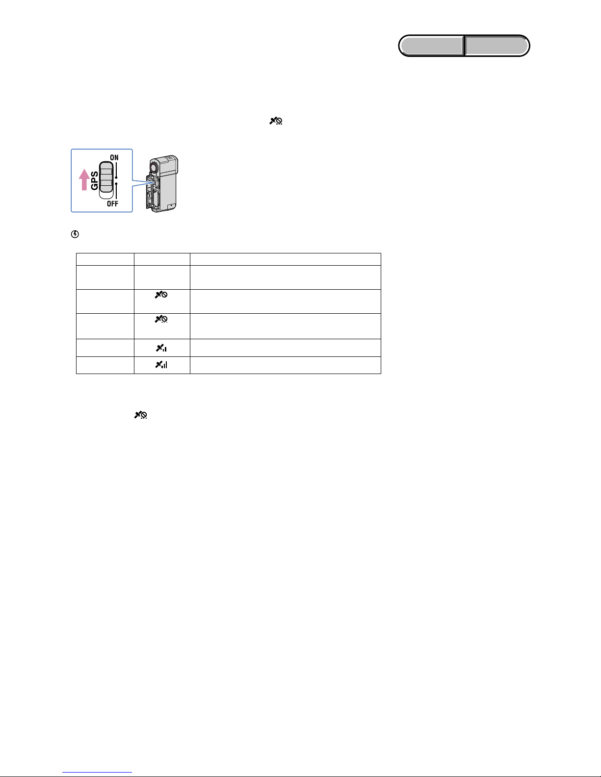
1-7. GPS RECEIVING CHECK (TG5V/TG5VE/TG7VE)
After a part of set was replaced or after the set was assembled, check the reception of GPS signal.
How to check the GPS function
Bring your camcorder to an open area, and set the GPS switch to ON ( appears on the LCD
screen). Your camcorder starts trying to triangulate. When your camcorder triangulates
successfully, it will record the location information at the time movies and photos were recorded.
• The indicator changes according to the strength of GPS signal reception.
Triangulating status GPS indicators GPS reception status
Function off No indicator
The GPS switch is set to OFF, or the GPS receiver is not
functioning normally.
Difficult
Your camcorder cannot find a GPS signal, therefore, it cannot
triangulate. Use your camcorder in an open area.
Processing
Your camcorder is confirming the GPS signal, and will be able
to acquire location information soon. Wait until your camcorder
completes the triangulation.
Triangulating
Your camcorder is receiving a GPS signal, and can acquire location
information.
Triangulating
Your camcorder is receiving a strong GPS signal, and can acquire
location information.
• It may take from several seconds to several minutes to acquire the location information when you use the
GPS for the first time or use it again after long intervals.
• You may not be able to acquire location information depending on the strength of GPS reception.
• When
is displayed and it takes a while to triangulate, set the GPS switch to OFF, then set to ON again.
Notes
1-7
ENGLISH JAPANESE
ENGLISH JAPANESE
HDR-TG5/TG5E/TG5V/TG5VE/TG7VE_L2
1. SERVICE NOTE
1-1. 修理時の電源供給について
本機では,安定化電源(8.4Vdc)からバッテリ端子に電源を供給した場合,約10秒後にシャットオフし,動作しなくなります。
これを避けるため,下記の方法を用いてください。
方法:
DC入力端子を使用する。(ACアダプタ(AC-L200C/L200D)を使用する。)
1-2. 内蔵メモリー(MS7308)交換時の注意
内蔵メモリー(MS-423基板に挿入されたMS7308)を交換の際は,AdjustStationからAdjustManualを起動させて「INTERNAL
MEMORYADJUSTMENTS」を参照してください。
TG5V/TG5VE/TG7VEのみ:
地図データ入り内蔵メモリー(MS-423基板に挿入されたMS7308)(TG5V/TG5VE/TG7VE)にはファクトリーチェックを行
わないでください。
ファクトリーチェックを行うと、地図データが消去されてしまいます。
1-3. VC-561基板交換時の注意
仕向けデータ
補修用基板と交換する時,補修用基板に書かれている仕向けデータは元の設定と違っている場合があります。
AdjustStationからAdjustManualを起動させて「DESTINATIONDATAWRITE」を実行させてください。
リストアデータ
補修用基板と交換する時,交換前の基板よりデータを取得してください。
データの取得はAdjustStationからAdjustManualを起動させて「RESTOREDATA」を実行させてください。
本機で取得されるデータは下記になります。
• USBSERIALNo.
USBシリアルNo.
セットは,1台毎に異なる固有のID(USBSerialNo.)を書き込んだ後,出荷されています。
新品の補修用基板には,このIDが書き込まれていないので,基板交換後にIDを入力する必要があります。
AdjustStationからAdjustManualを起動させて「USBSERIALNo.INPUT」を実行させてください。
1-4. 使用サービス治具
延長ケーブル(J-6082-656-A)をDD-312基板CN1101とVC-561基板CN1001の間に接続します。
VC-561基板(B面側)
延長ケーブル(120P)
J-6082-656-A
DD-312基板(A面側)
CN1001
CN1101
1-8
ENGLISH JAPANESE
ENGLISH JAPANESE
HDR-TG5/TG5E/TG5V/TG5VE/TG7VE_L2
1-5. 自己診断機能
1-5-1. 自己診断機能について
本機の動作に不具合が生じたとき,自己診断機能が働き,
LCD画面に,どう処置したらよいか判断できる表示を行い
ます。自己診断機能については取扱説明書にも掲載されて
います。
1-5-2. 自己診断表示
本機の動作に不具合が生じたとき,ビューファインダまた
はLCD画面のカウンタ表示部分がアルファベットと数字の
4桁表示になり,3.2Hzで点滅します。この5 文字の表示に
よって対応者分類および不具合の生じたブロックの分類,
不具合の詳細コードを示します。
1 1
3 1C
対応者分類
「1-5-3.自己診断コード表」
を参照
対応方法の違いにより分類
例 31 ・・・テープを入れ直す
32 ・・・電源を入れ直す
ブロック分類
詳細コード
3.2Hz点滅
C :お客さま自身で対応
H :販売店で対応
E :サービスエンジニア
で対応
LCD画面
C : 3 1 : 1 1
1-9
ENGLISH JAPANESE
ENGLISH JAPANESE
HDR-TG5/TG5E/TG5V/TG5VE/TG7VE_L2
症状/状態
標準以外のバッテリを使用している
バッテリーが高温になっている
フォーマットしていないメモリー
ステックデュオを入れた
メモリーステックデュオが壊
れている
アクセスエラー
フォーカスが合いにくい
(フォーカスの初期化ができない)
フラッシュメモリが書き換えられて
いる
ドライブ不良
ズーム動作の異常(ズームレンズの
初期化ができない)
フォーカス,ズーム異常
手振れ補正が効きにくい(PITCH
角速度センサ出力張り付き)
手振れ補正が効きにくい(YAW角
速度センサ出力張り付き)
フラッシュの充電異常
フラッシュメモリの書込み/消去動
作不良
フォーマットしていない内蔵メモ
リーを入れた
内蔵メモリーが壊れている
BGMデータ不良
GPSハードエラー
地図領域マウントエラー
対応/方法
インフォリチウムバッテリを使用する。
バッテリーを交換するか,バッテリーを涼しいところに置
く。
メモリーステックデュオをフォーマットする。
新しいメモリーステックデュオに交換する。
電源を外し,再度入れ直してから操作する。
操作スイッチの電源を入れ直す。
復帰しない場合,レンズブロックのフォーカスMRセンサ
(VC-561基板CN10031,2ピン)を点検する。異常なけ
ればフォーカスモータ駆動回路(VC-561基板IC5201)を点
検する。
フラッシュメモリのデータを元の値に戻す。(注1)
内蔵メモリー(MS7308)を点検または交換する。
ズームレバーを操作したときにズーム動作をすれば,レン
ズブロックのズームリセットセンサ(VC-561基板CN1003
wfピン)を点検する。ズーム動作をしなければズームモー
タ駆動回路(VC-561基板IC5203)を点検する。
自己診断コードC:32:60とE:61:10の両方を点検する。
PITCH/YAW角速度センサ(GY-016基板SE6601)周辺回路
を点検する。
PITCH/YAW角速度センサ(GY-016基板SE6601)周辺回路
を点検する。
フラッシュユニットの点検または交換をする。
フラッシュメモリ(VC-561基板IC2101)を点検する。
内蔵メモリー(MS7308)をフォーマットする。
新しい内蔵メモリー(MS7308)に交換する。(注2)
フラッシュメモリ(VC-561基板IC2101)を点検する。異常
なければCPU(VC-561基板IC1701)を点検する。
TG5V/TG5VE/TG7VE:
フレキ切れ,半差し等の点検を行う。問題がない場合は
GPSモジュールを点検または交換する。
TG5V/TG5VE/TG7VE:
内蔵メモリー(MS7308)を点検または交換する。
1-5-3. 自己診断コード表
C
C
C
C
C
E
E
E
E
E
E
E
E
E
E
E
E
ブロック
機能
04
06
13
13
32
20
31
61
61
62
62
91
94
94
94
95
96
詳細
コード
00
00
01
02
60
00
00
10
11
00
01
01
00
01
02
00
00
自己診断コード
対
応
者
注1: AdjustStationからAdjustManualを起動させて「DESTINATIONDATAWRITE」を参照してください。
注2: AdjustStationからAdjustManualを起動させて「INTERNALMEMORYADJUSTMENTS」を参照してください。
1-10
ENGLISH JAPANESE
ENGLISH JAPANESE
HDR-TG5/TG5E/TG5V/TG5VE/TG7VE_L2
1-6. キャビネット(L)交換時の注意
1-6-1. キャビネット(L)注文時の注意
機種の表示部はレーザー印字方式を採用しております。
この為,交換用のキャビネット(L)は機種,仕向けにより
異なります。類似の表示もありますので,該当するものを
選んで注文してください。
注意: キャビネット(L)交換後はシリアルナンバーがサー
ビス専用のシリアルナンバーに変更されます。お客
様への案内と修理データのシリアルナンバー変更を
行ってください。
シリアルナンバー
シリアルナンバー
シリアルナンバー
シリアルナンバー
シリアルナンバー
シリアルナンバー シリアルナンバー
シリアルナンバー シリアルナンバー
シリアルナンバー
HDR-TG5 (E, JE仕向)
A-1726-248-A サ-ビス用キャビL (TG5-E23)
HDR-TG5 (KR仕向)
A-1726-249-A サ-ビス用キャビL (TG5-KR2)
HDR-TG5E (E, HK, JE仕向)
A-1726-251-A サ-ビス用キャビL (TG5-E34)
HDR-TG5E (CH仕向)
A-1726-252-A サ-ビス用キャビL (TG5-CN2)
HDR-TG5V (J仕向)
A-1726-242-A サ-ビス用キャビL (TG5-J1)
HDR-TG5V (US仕向)
A-1726-244-A サ-ビス用キャビL (TG5-U2)
HDR-TG5V (CND仕向)
A-1726-245-A サ-ビス用キャビL (TG5-CA2)
HDR-TG5VE (AEP仕向)
A-1726-246-A サ-ビス用キャビL (TG5-CEN)
HDR-TG5VE (AUS仕向)
A-1726-247-A サ-ビス用キャビL (TG5-AU2)
HDR-TG7VE (AEP, UK仕向)
A-1726-253-A サ-ビス用キャビL (TG7-CEH)
部品コード 部 品 名 部品コード 部 品 名
部品コード 部 品 名
部品コード 部 品 名 部品コード 部 品 名
部品コード 部 品 名
部品コード 部 品 名 部品コード 部 品 名 部品コード 部 品 名
部品コード 部 品 名
1-11
ENGLISH JAPANESE
ENGLISH JAPANESE
HDR-TG5/TG5E/TG5V/TG5VE/TG7VE_L2
1-6-2. 日本向けモデルのキャビネット(L)交換時の注意
交換前のキャビネット(L)に印字されている製造年(下図の○部の表示)と同じ表示のラベルを新しいキャビネット(L)に
貼付けてください。
例:下図では,09年製のラベルを貼る
*ラベルは,サービス用キャビネット(L)部組に「投げ込み(ラベル貼り方)」を含めて同梱されています。
1-6-3. US向けモデルのキャビネット(L)交換時の注意
交換前のキャビネット(L)に印字されている製造年月(下図の○部の表示)と同じ表示のラベルを新しいキャビネット(L)
に貼付けてください。
例:下図では,9AとSKDのラベルを貼る
*ラベルは,サービス用キャビネット(L)に「投げ込み(ラベル貼り方)」を含めて同梱されています。
1-6-4. 韓国向けモデルのキャビネット(L)交換時の注意
交換前のキャビネット(L)に印字されている製造年月(下図の○部の表示)と同じ表示のラベルを新しいキャビネット(L)
に貼付けてください。
例:下図では,2009.1のラベルを貼る
*ラベルは,サービス用キャビネット(L)に「投げ込み(ラベル貼り方)」を含めて同梱されています。
*
ラベルを貼付けてください
*
製造年
HDR-TG5V (J仕向)
*
ラベルを貼付けてください
*
製造年
*
製造所
HDR-TG5V (US仕向)
*
ラベルを貼付けてください
*
製造年
HDR-TG5 (KR仕向)
1-12E
ENGLISH JAPANESE
ENGLISH JAPANESE
HDR-TG5/TG5E/TG5V/TG5VE/TG7VE_L2
1-7. GPS受信確認(TG5V/TG5VE/TG7VE)
部品交換やセット組み立て後は,GPS信号受信確認を行ないます。
GPS機能確認方法
空の開けた場所で,GPSスイッチを「ON」にすると、が表示され、測位準備が行われます。
測位できた場合、動画・静止画の撮影時に位置情報を記録します。
ご注意
• GPS衛星からの電波の受信状況によって画面に表示されるアイコンが変わります。
測位状況 画面表示 GPS受信状況
機能切 非表示 GPSスイッチが「OFF」になっている、
またはエラーが起きている。
測位困難 GPS信号を受信できないため、位置情報が取れない。
空の開けた場所に移動してください。
測位計算中 GPS信号を確認中。しばらくすると位置情報を取得で
きる。測位中になるまでお待ちください。
測位中 GPS信号を受信中。位置情報を取得できる。
測位中 強いGPS信号を受信中。位置情報を取得できる。
• 初めて使う場合やしばらく使わなかった場合は、位置情報を取得できるまで
数十秒から数分かかることがあります。
• GPS受信状況によっては位置情報を取得できないことがあります。
• しばらくの間が表示されて測位に時間がかかる場合は、GPSスイッチを一度
「OFF」にして、再度「ON」にしてください。
2-1
HDR-TG5/TG5E/TG5V/TG5VE/TG7VE_L2
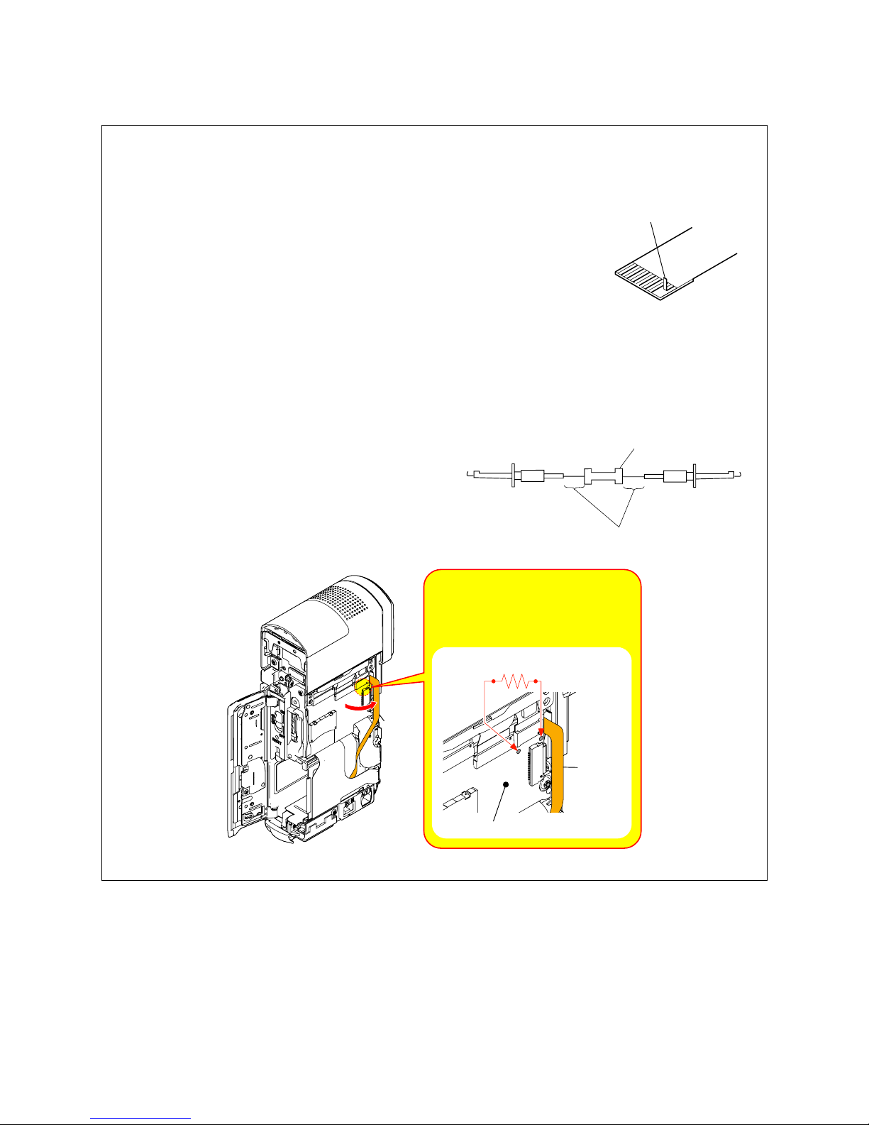
2. DISASSEMBLY
Cut and remove the part of gilt
which comes off at the point.
(Be careful or some
pieces of gilt may be left inside)
NOTE FOR REPAIR
• Make sure that the flat cable and flexible board are not cracked of bent at the terminal.
Do not insert the cable insufficiently nor crookedly.
• When remove a connector, don’t pull at wire of connector. It is possible that a wire is snapped.
• When installing a connector, don’t press down at wire of connector.
It is possible that a wire is snapped.
DISCHARGING OF MS-423 BOARD’S CHARGING CAPACITOR (C001)
The charging capacitor (C001) of MS-423 board is charged up
to the maximum 330 V potential.
There is a danger of electric shock by this high voltage when the
capacitor is handled by hand. The electric shock is caused by
the charged voltage which is kept without discharging when the
main power of the unit is simply turned off. Therefore, the
remaining voltage must be discharged as described below.
1 kΩ/1 W
Wrap insulating tape.
Preparing the Short Jig
To preparing the short jig, a small clip is attached to each end of
a resistor of 1 kΩ /1 W (1-215-869-11).
Wrap insulating tape fully around the leads of the resistor to
prevent electrical shock.
MS-423 Board
Note: High-voltage cautions
Discharging the Capacitor
Short-circuit between the two points
with the short jig about 10 seconds.
R:1 kΩ/1 W
(Part code: 1-215-869-11)
FP-1083
Flexible
Board
FP-1083
Flexible
Board
2-2
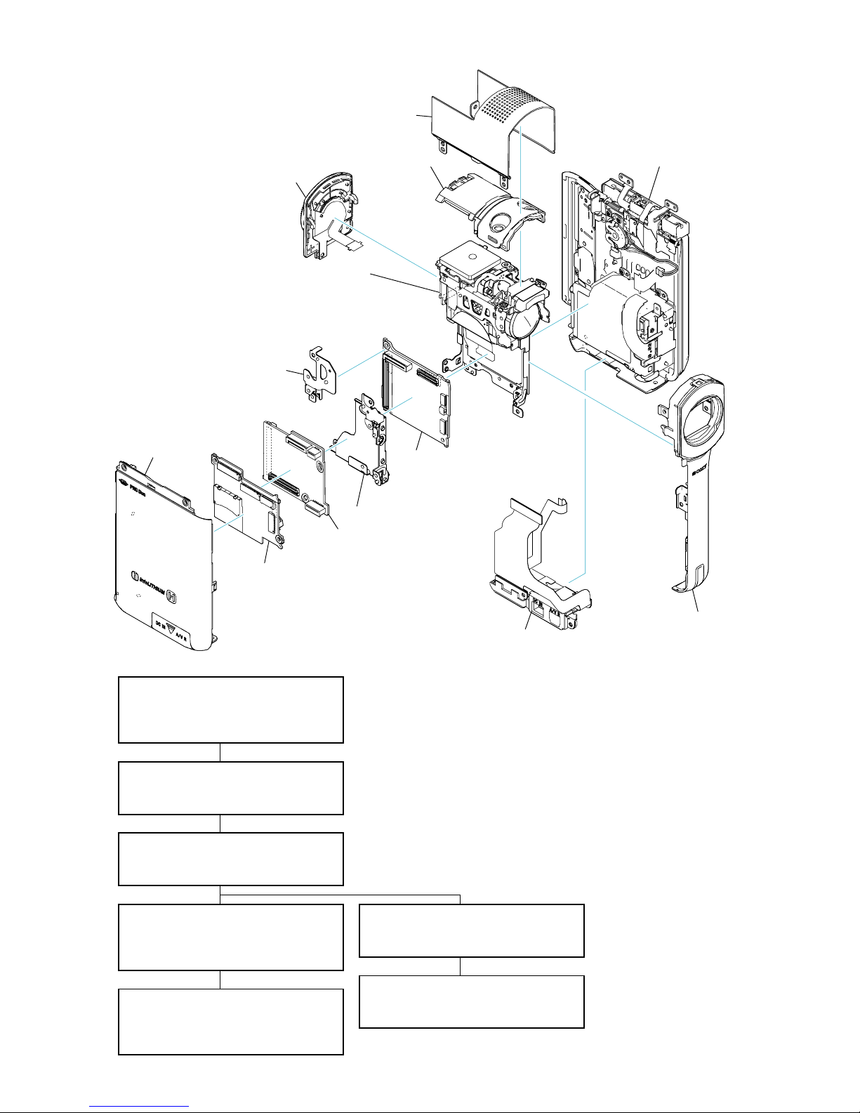
HDR-TG5/TG5E/TG5V/TG5VE/TG7VE_L2
2-1. IDENTIFYING PARTS
2-2-3. JACK HOLDER SECTION
⋅ Jack Holder Block
⋅ Cabinet (R)
2-2-4. MAIN BOARD SECTION
⋅ Top Cabinet (Inner)
⋅ DD-312 Board
⋅ VC-561 Board
2-2-6. CABINET (R) SECTION
⋅ LCD Panel
⋅ BT Frame
2-2-5. LENS BLOCK SECTION
⋅ GM-055 Assy (TG5V/TG5VE/TG7VE)
⋅ GY-016 Board
⋅ Lens Block
2-2-1. OVERALL SECTION
⋅ Control Switch Block (PS31500)
⋅ Cabinet (L)
⋅ Cabinet (Top)
2-2-2. FRONT/MS BOARD SECTION
⋅ Cabinet (Front)
⋅ MS-423 Board
2-2-7.LCD PANEL SECTION
⋅ Hinge Block
⋅ LCD
- DISASSEMBLY FLOW -
Cabinet (R)
⋅ FP-1077 Flexible Board
⋅ FP-1082 Flexible Board
Lens Block
⋅ CM-110 Board
⋅ GY-016 Board
⋅ FP-1078 Flexible Board
⋅ FP-1084 Flexible Board
Jack Holder
⋅ FP-1076 Flexible Board
⋅ FP-1083 Flexible Board
Top Cabinet (Inner)
Control Switch Block
(PS31500)
Cabinet (Top)
Cabinet (L)
Frame (Rear)
Main Frame
Cabinet (Front)
MS-423 Board
VC-561 Board
⋅ FP-1079 Flexible Board
⋅ FP-1080 Flexible Board
DD-312 Board
⋅ FP-1081 Flexible Board
2-3
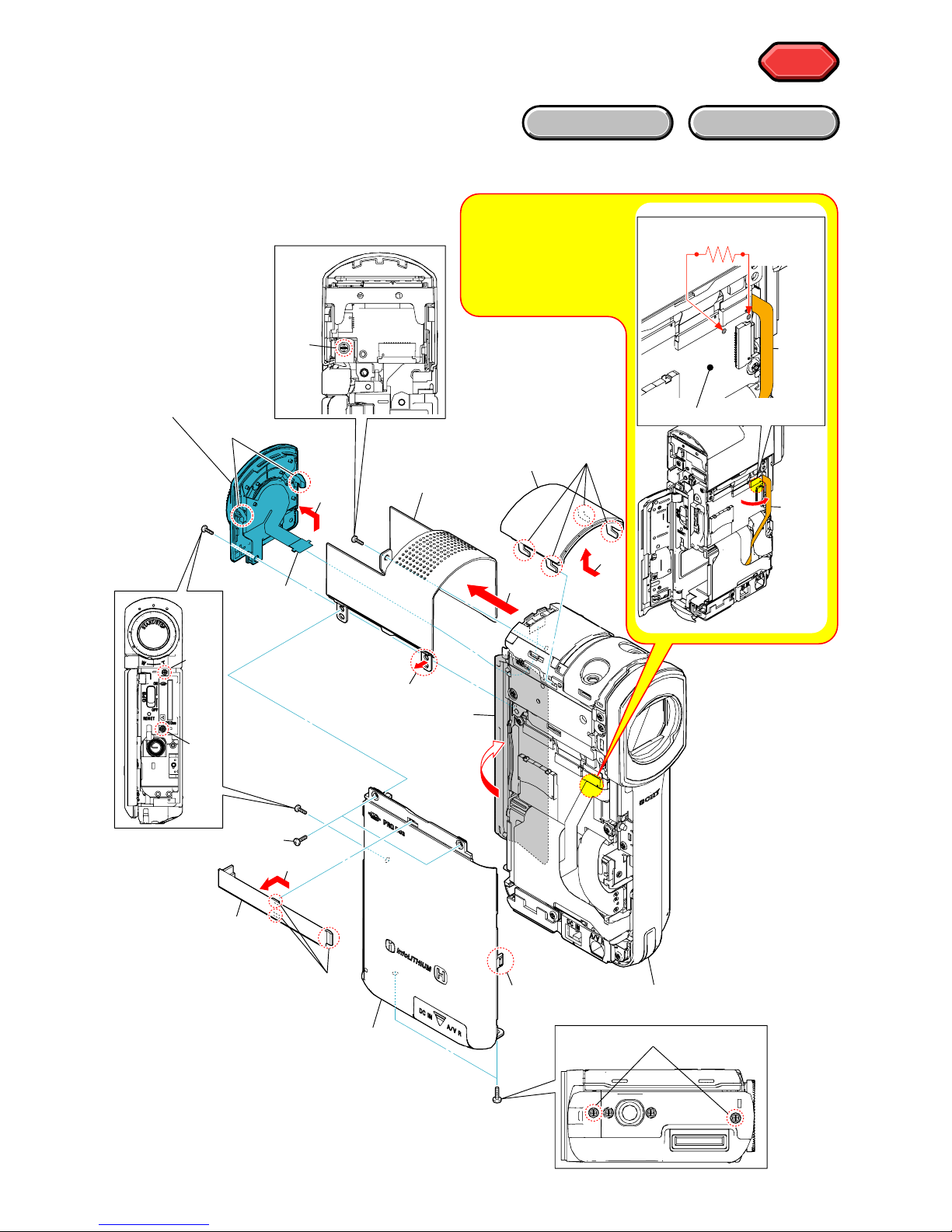
HDR-TG5/TG5E/TG5V/TG5VE/TG7VE_L2
2-2. DISASSEMBLY
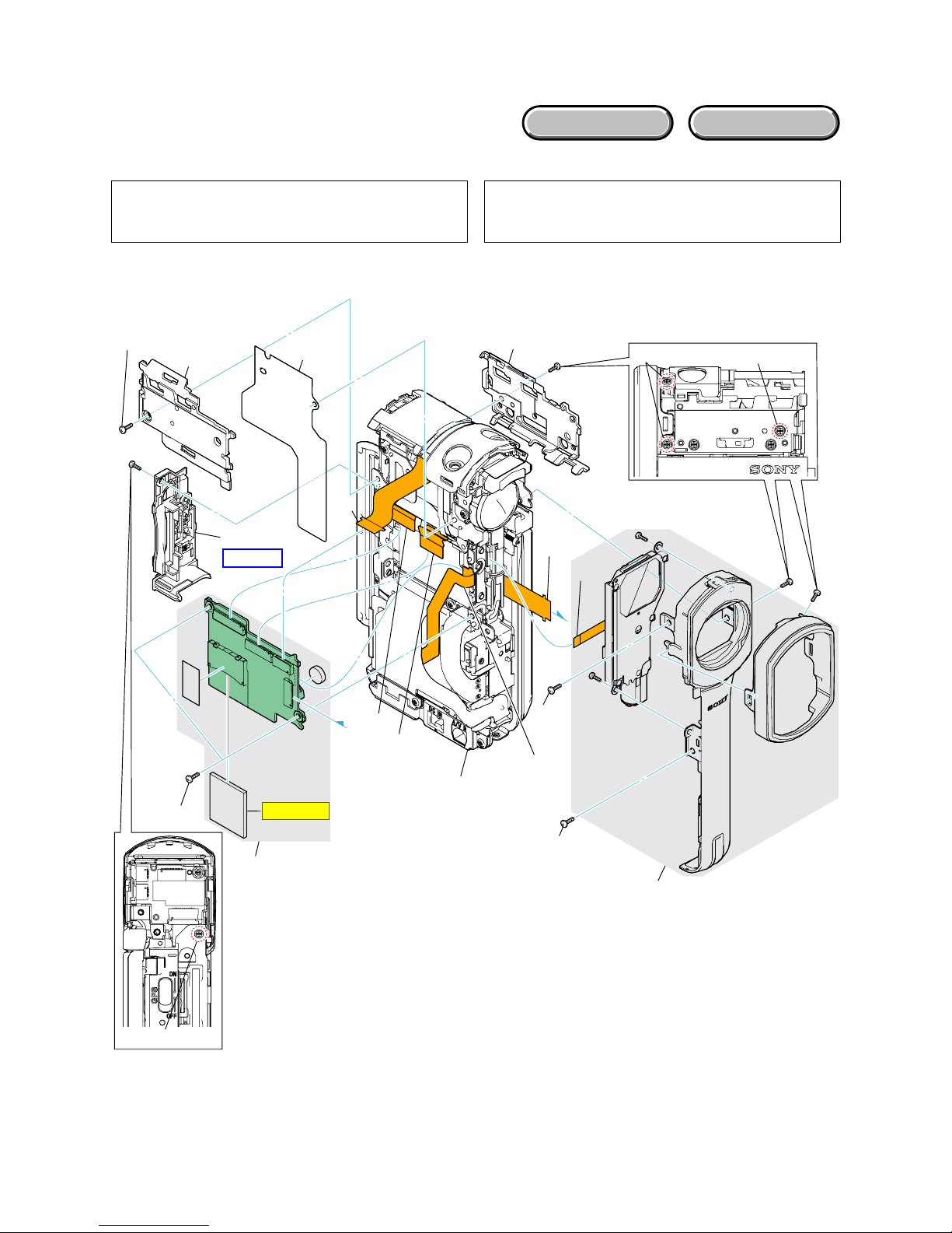
2-2-1. OVERALL SECTION
Follow the disassembly in the numerical order given.
1 Control Switch Block (PS31500) (1-1 to 1-5)
2 Cabinet (L) (2-1 to 2-7)
3 Cabinet (Top) (3-1 to 3-6)
HELP
HELP
EXPLODED VIEW
HARDWARE LIST
1 Control Switch
Block
(PS31500)
1-1
(Open)
1-2
(#2)
1-4 (Claw)
1-3
1-5E
2 Cabinet (L)
2-1
2-3
2-2
(Claw)
2-7E
(Claw)
2-4 (#2)
Front/MS Board Section
(See Page 2-4)
2-5
(#2)
2-6 (#2)
3-6E
3-5
3-4
(#14)
3-1
3-2
(Claw)
3-3
3 Cabinet (Top)
Note: High-voltage cautions
Discharging the Capacitor
Short-circuit between the two
points with the short jig about
10 seconds.
FP-1083
Flexible
Board
MS-423 Board
R:1 kΩ/1 W
(Part code: 1-215-869-11)
FP-1083
Flexible
Board
2-4
HDR-TG5/TG5E/TG5V/TG5VE/TG7VE_L2
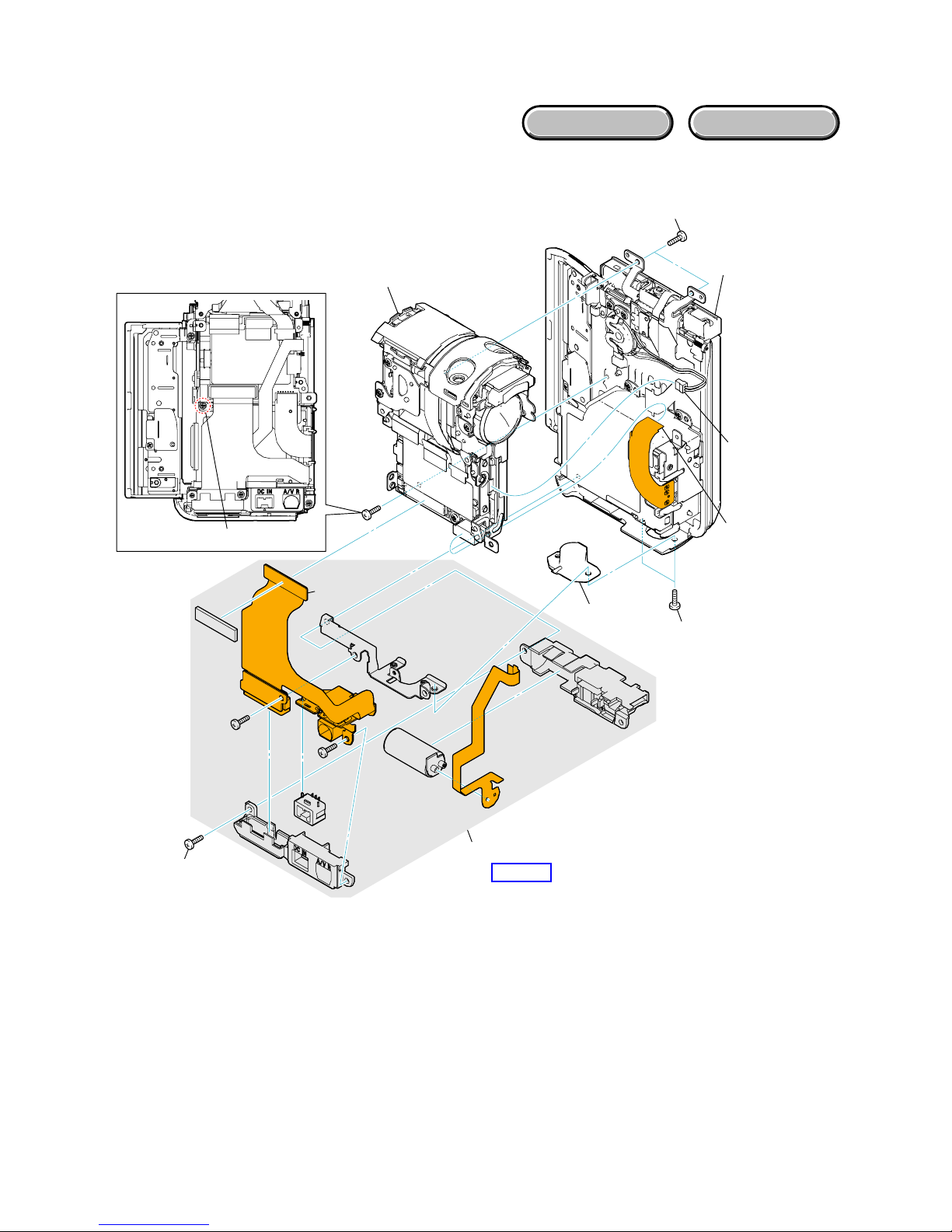
2-2-2. FRONT/MS BOARD SECTION
Follow the disassembly in the numerical order given.
1 Cabinet (Front) (1-1 to 1-4)
2 MS-423 Board (2-1 to 2-13)
EXPLODED VIEW
HARDWARE LIST
A
A
1 Cabinet (Front)
1-1 (#14)
1-2
(#14)
2 MS-423 Board
2-1 (#14)
2-2
Jack Holder Section
(See Page 2-5)
2-3 (#14)
2-12 (#3)
2-13E
2-6 (#14)
2-5
2-4
2-7
2-8
2-10
2-11
2-9
1-3
(#14)
1-4E
MS-423
Note 1, 2
HELP07
Note 1: When replacing the internal memory (MS7308 that has
been inserted in the MS-423 board), start the Adjust
Manual in the Adjust Station and refer to the “INTERNAL
MEMORY ADJUSTMENTS”.
Note 2: Do not factory check the internal memory (MS7308 that
has been inserted in the MS-423 board) in which Map
Data is installed (TG5V/TG5VE/TG7VE). The map data is
erased when the factory check is done.
2-5
HDR-TG5/TG5E/TG5V/TG5VE/TG7VE_L2
2-2-3. JACK HOLDER SECTION
Follow the disassembly in the numerical order given.
1 Jack Holder Block (1-1 to 1-4)
2 Cabinet (R) (2-1 to 2-4)
EXPLODED VIEW
HARDWARE LIST
1 Jack Holder Block
1-2 (#43)
1-3 (#2)
1-4E
1-1
2-1
2-2
2-3 (#14)
2-4E
(#14)
Main Board Section
(See Page 2-6)
HELP01
2 Cabinet (R)
(See Page 2-8)
2-6
HDR-TG5/TG5E/TG5V/TG5VE/TG7VE_L2
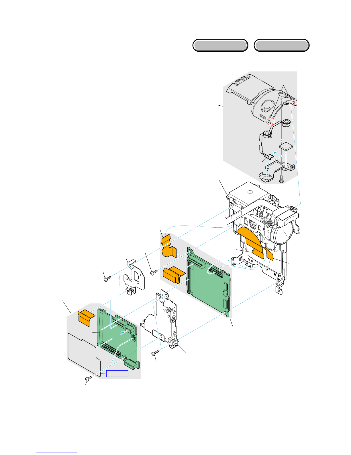
2-2-4. MAIN BOARD SECTION
Follow the disassembly in the numerical order given.
1 Top Cabinet (Inner) (1-1 to 1-2)
2 DD-312 Board (2-1 to 2-2)
3 VC-561 Board (3-1 to 3-8)
EXPLODED VIEW
HARDWARE LIST
VC-561
DD-312
1 Top Cabinet (Inner)
2 DD-312 Board
Lens Block Section
(See Page 2-7)
2-1 (#3)
2-2E
1-1
1-2E
(Claw)
A
A
HELP02
3-3 (#14)
3-1 (#14)
3-2
3-7 (#3)
3-4
3-5
3-6
3-8E
3 VC-561 Board
2-7
HDR-TG5/TG5E/TG5V/TG5VE/TG7VE_L2
EXPLODED VIEW
HARDWARE LIST
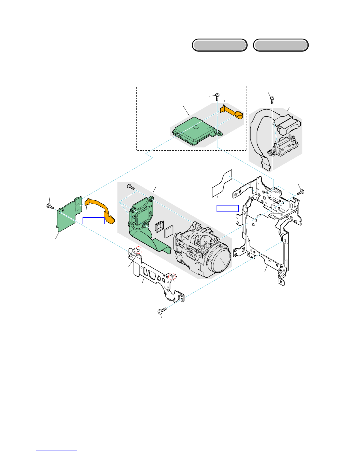
2-2-5. LENS BLOCK SECTION
Follow the disassembly in the numerical order given.
1 GM-055 Assy (TG5V/TG5VE/TG7VE) (1-1 to 1-2)
2 GY-016 Board (2-1 to 2-2)
3 Lens Block (3-1 to 3-9)
1 GM-055 Assy
2 GY-016 Board
2-2E
(#3)
2-1
1-1
1-2E
(#3)
HELP03
HELP04
3-1 (#14)
3-2
3 Lens Block
3-3 (#14)
3-4 (Boss)
3-5 (Claw)
3-7
3-6
3-8 (#5)
3-9E
GY-016
TG5V/TG5VE/TG7VE
 Loading...