

Page 1
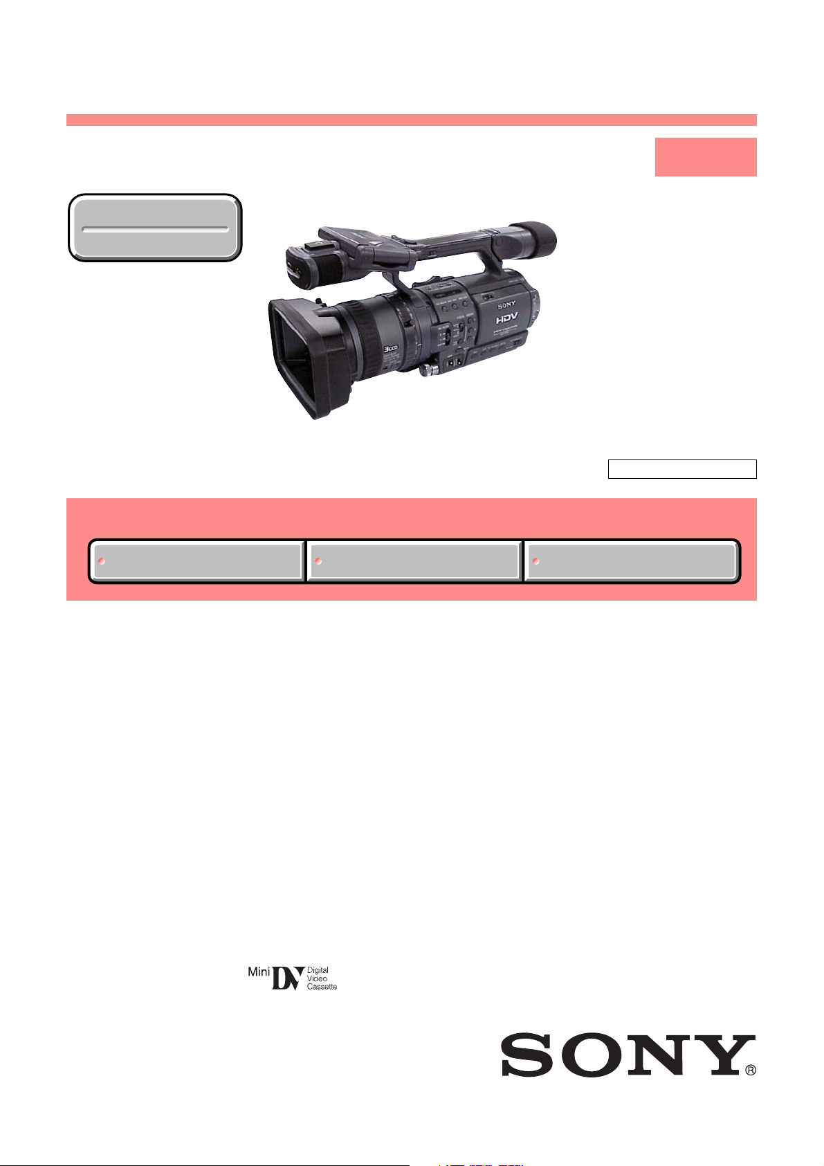
HDR-FX1/FX1E
RMT-840
SERVICE MANUAL
Ver 1.0 2004. 09
Revision History
Revision History
Photo : HDR-FX1
Link
Link
SPECIFICATIONS
SPECIFICATIONS
ACCESSORIES
ACCESSORIES
LEVEL 1
HDR-FX1
US Model
Canadian Model
Korea model
HDR-FX1E
AEP model
UK model
Australian model
Chinese moedl
Hong Kong model
HDR-FX1/FX1E
E model
Tourist model
Z (Z310) MECHANISM
SELF DIAGNOSIS FUNCTION
SELF DIAGNOSIS FUNCTION
• INSTRUCTION MANUAL is shown at the end of this document.
DIGITAL HD VIDEO CAMERA RECORDER
HDR-FX1/FX1E
9-876-770-41
Sony EMCS Co.
2004I1600-1
©2004.9
Published by DI Technical Support Section
Page 2

System
Video recording system (HDV)
2 rotary heads, Helical scanning system
Video recording system (DV)
2 rotary heads, Helical scanning system
Audio recording sys t em (HDV)
Rotary heads, MPEG-1 Audio Layer2
Quantization: 16 bits (Fs 48 kHz, stereo)
Transfer rate: 384 kbps
Audio recording sys t em (DV)
Rotary heads, PCM system
Quantization: 12 bits (Fs 32 kHz, stereo 1,
stereo 2), 16bits (Fs 48 kHz, st er eo)
Video signal
HDR-FX1:
N
TSC color, EIA standards, 1080/60i
specification
HDR-FX1E:
PAL color, CCIR standards, 1080/50i
specification
Usable cassette
Mini DV cassette with the mark
printed
Tape speed (HDV)
Approx. 18.81 mm/s
Tape speed (DV)
SP: Approx. 18.81 mm/s
LP: Approx. 12.56 mm/s
Recording/playback time (HDV)
60 min (using a DVM60 cassette)
Recording/playback time (DV)
SP: 60 min (using a DVM60 cassette)
LP: 90 min (using a DVM60 cassette)
Fast forward/rewind time
Approx. 2 min 40 s (using a DVM60 cassette)
Viewfinder
Electric viewfinder (color)
Image device
6 mm (1/3 type) 3CCD (Charge Co upled
Device)
Gross: Approx. 1 120 000 p ixel s
Effective: Approx. 1 070 000 pixels
Lens
Carl Zeiss Vario-Sonnar T*
Combined power zoom lens
Filter diameter: 72 mm (2 7/ 8 in.)
12 (O ptical)
F = 1.6 ~ 2.8
Focal length
4.5-54mm (3/16- 21/4in.)
When converted to a 35 mm still camera
32.5 - 390 mm (1 5/16 - 15 3/8 in.)
(40 - 480 mm (1 5/8 - 19 in.) in 4:3 TV mode)
Color tempe r ature
[AUTO], [ONE-PUSH A/B], [INDOOR]
(3 200 K), [OUTDOOR] (5 800 K)
Minimum illumination
3 lx (lux) (F 1.6)
SPECIFICATIONS
Input/Output connectors
Audio/Video input/output
Video signal: 1 Vp-p, 75 Ω (ohms),
unbalanced, sync negative
Audio signal: 327 mV (at load im pedance
47 kΩ (kilohms)), Input impedance more than
47 kΩ (kilohms), Output impedance less than
2.2 kΩ (kilohms)
S VIDEO input/output
Luminance signal: 1 Vp-p, 75 Ω (ohms),
un
balanced
HDR-FX1:
Chrominance signal: 0.28 6 Vp-p, 75 Ω
(ohms), unbalanced
HDR-FX1E:
Chrominance signal: 0.3 Vp-p, 75 Ω (ohms),
unbalanced
COMPONENT OUTPUT jack
Y: 1 Vp-p (0.3 V sync ne gat ive)
B/PR, CB/CR: +/- 350 mVp-p, Inpu t
P
impedance 75Ω (ohm s)
Headphones jack
Stereo minijack (Ø 3.5 mm)
LANC jack
Stereo mini-minij ack (Ø 2.5 mm)
MIC jack
Minijack, 0.388 mV low impedance with DC
2.5 to 3.0 V , ou tput impedance 6.8 kΩ
(kilohms) (Ø 3.5 mm), Stereo type
HDV/DV jack
i.LINK Interface (IEEE1394, 4-pin connector
S100)
LCD screen
Picture
8.8 cm (3 .5 type )
Total dot number
250 000 (1 120 × 224)
General
Power requirement s
DC 7.2 V (battery pack)
DC 8.4 V (AC Adaptor)
Average power consumption (when using the
battery pack)
During camera recording using the viewfinder
w
ith normal brig htness:
HDR-FX1:
HDV recordin g 7.4 W
DV recording 6. 9 W
HDR-FX1E:
HDV recordin g 7.3 W
DV recording 6. 9 W
During camera reco rding using the LCD with
normal brightness:
HDR-FX1:
H
DV recording 8.0 W
DV recording 7. 5 W
HDR-FX1E:
HDV recordin g 7.9 W
DV recording 7. 5 W
Operating temp erature
0°C to 40°C (32°F to 104°F)
Storage temperature
-20°C to + 60°C (-4°F to + 140°F)
Dimensions (approx.)
151 × 181 × 365 mm (6 × 71/4 × 14 3/8 in.)
(w/h/d)
Mass (Approx.)
2.0 kg (4 lb 6 1/2 oz) main unit on ly
2.1 kg (4 lb 10 1/8 oz) including the NP-F570
rechargeable battery pack, DVM60 cassette
and lens hood.
Supplied accessories
See page 4.
AC Adaptor AC-L15A/L15B
Power requirement s
AC 100 - 240 V, 50/60 Hz
Current consumption
0.35 - 0.18 A
Power consumption
18 W
Output voltage
DC 8.4 V, 1.5 A
Operating temp erature
0°C to 40°C (32°F to 104°F)
Storage temperature
-20°C to + 60°C (-4°F to + 140°F)
Dimensions (approx.)
56 × 31 × 100 mm (2 1/4 × 11/4 × 4 in.) (w/h/
d) excluding the pr ojecting parts
Mass (approx.)
190 g (6.7 oz) excluding the power cord
Rechargeable battery pack (NP-F570)
Maximum output voltage
DC 8.4 V
Output voltage
DC 7.2 V
Capacity
15.8 Wh (2 200 mAh)
Dimensions (approx.)
38.4 × 20.6 × 70.8 mm
(1 9/16 × 13/16 × 2 7/8 in.) (w/h/d)
Mass (approx.)
100 g (3.5 oz)
Operating temperature
0°C to 40°C (32°F to 104°F)
Type
Lithium ion
Design and specifications are subject to ch
without notice.
HDR-FX1/FX1E
— 2 —
Page 3

SAFETY CHECK-OUT
After correcting the original service problem, perform the following
safety checks before releasing the set to the customer.
1. Check the area of your repair for unsoldered or poorly-soldered
connections. Check the entire board surface for solder splashes
and bridges.
2. Check the interboard wiring to ensure that no wires are
"pinched" or contact high-wattage resistors.
3. Look for unauthorized replacement parts, particularly
transistors, that were installed during a previous repair . Point
them out to the customer and recommend their replacement.
SAFETY-RELATED COMPONENT WARNING!!
COMPONENTS IDENTIFIED BY MARK 0 OR DOTTED LINE WITH
MARK 0 ON THE SCHEMATIC DIAGRAMS AND IN THE PARTS
LIST ARE CRITICAL TO SAFE OPERATION. REPLACE THESE
COMPONENTS WITH SONY PARTS WHOSE PART NUMBERS
APPEAR AS SHOWN IN THIS MANUAL OR IN SUPPLEMENTS
PUBLISHED BY SONY.
CAUTION :
Danger of explosion if battery is incorrectly replaced.
Replace only with the same or equivalent type.
4. Look for parts which, through functioning, show obvious signs
of deterioration. Point them out to the customer and
recommend their replacement.
5. Check the B+ voltage to see it is at the values specified.
6. Flexible Circuit Board Repairing
• Keep the temperature of the soldering iron around 270˚C
during repairing.
• Do not touch the soldering iron on the same conductor of the
circuit board (within 3 times).
• Be careful not to apply force on the conductor when soldering
or unsoldering.
ATTENTION AU COMPOSANT AYANT RAPPORT
À LA SÉCURITÉ!
LES COMPOSANTS IDENTIFÉS PAR UNE MARQUE 0 SUR LES
DIAGRAMMES SCHÉMATIQUES ET LA LISTE DES PIÈCES SONT
CRITIQUES POUR LA SÉCURITÉ DE FONCTIONNEMENT. NE
REMPLACER CES COMPOSANTS QUE PAR DES PIÈSES SONY
DONT LES NUMÉROS SONT DONNÉS DANS CE MANUEL OU
DANS LES SUPPÉMENTS PUBLIÉS PAR SONY.
HDR-FX1/FX1E
— 3 —
Page 4
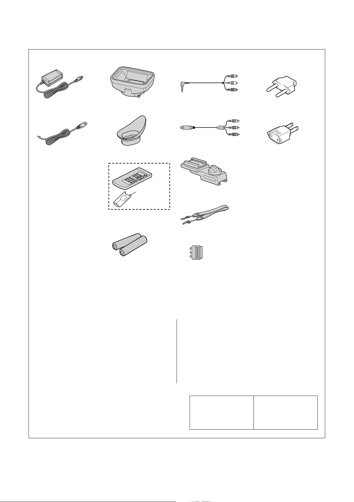
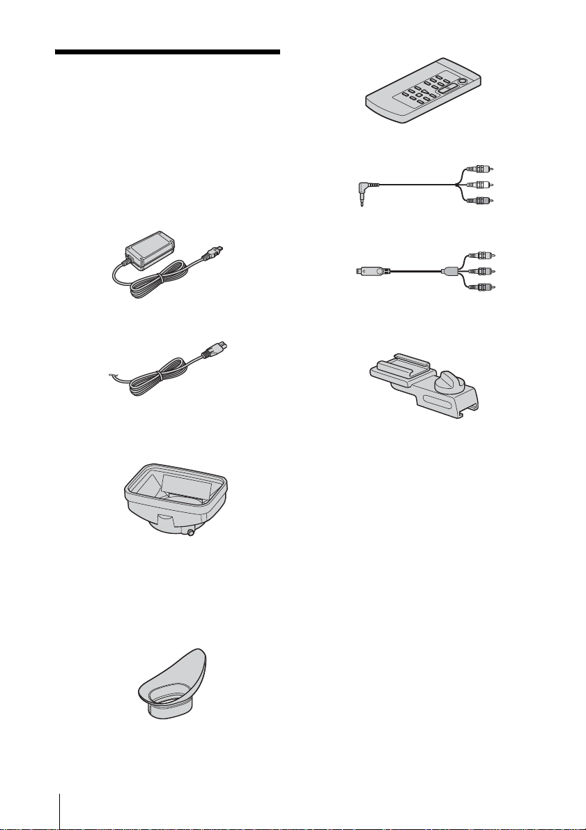
Checking supplied accessories.
Make sure that the following accessories are supplied with your camcorder.
AC adaptor
(AC-L15A/L15B)(1)
0
1-477-533-51
Power cord (Main lead)(1)
(US, CND model)
0
1-790-107-22
Power cord (Main lead)(1)
(AEP model)
0
1-823-150-11
Power cord (Main lead)(1)
(UK model)
0
1-757-401-11
Power cord (Main lead)(1)
(E model)
0
1-769-608-11
Power cord (Main lead)(1)
(HK model)
0
1-783-374-11
Power cord (Main lead)(1)
(JE model)
0
1-790-732-12
Power cord (Main lead)(1)
(KR model)
0
1-823-947-11
Power cord (Main lead)(1)
(AUS model)
0
1-827-945-11
Power cord (Main lead)(1)
(CH model)
0
1-782-476-13
Lens hood (1)
2-186-430-01
Large eyecup (1)
2-179-414-01
Lid battery
case (1)
3-742-854-01
Wireless remote commander
(RMT-840)(1)
1-478-953-21
R6 (size AA) batteries
for the Remote
Commander (2)
(not supplied)
A/V connecting cable (1)
1-824-097-11
Component video cable (1)
1-829-414-21
Shoe adaptor (1)
X-2023-305-1
Shoulder strap (1)
2-021-016-01
21-pin adaptor (1)
(AEP, UK model)
1-770-783-21
2-pin conversion adaptor (1)
(JE model)
1-569-007-12
2-pin conversion adaptor (1)
(E, HK model)
1-569-008-12
Rechargeable battery pack
(NP-F570)(1)
(not supplied)
Cleaning cassette
(DVM-4CLD J)(1)
8-883-121-64
• Abbreviation
CND : Canadian model
AUS : Australian model
CH : Chinese model
HK : Hong Kong model
KR : Korea model
JE : Tourist model
Other accessories
2-178-348-11 MANUAL, INSTRUCTION (ENGLISH)(FX1:US,CND,E,JE)
2-178-348-21 MANUAL, INSTRUCTION (FRENCH)(FX1:CND)
2-178-348-31 MANUAL, INSTRUCTION (SPANISH/PORTUGUESE)
2-178-348-41 MANUAL, INSTRUCTION (TRADITIONAL CHINESE)
2-178-348-51 MANUAL, INSTRUCTION (KOREAN)(FX1:JE,KR)
HDR-FX1/FX1E
(FX1:E,JE)
(FX1:E)
— 4 —
2-178-349-11 MANUAL, INSTRUCTION (ENGLISH)(FX1E)
2-178-349-21 MANUAL, INSTRUCTION (RUSSIAN)(FX1E:E,JE,AEP)
2-178-349-31 MANUAL, INSTRUCTION (SPANISH/PORTUGUESE)
2-178-349-41 MANUAL, INSTRUCTION (FRENCH/GERMAN)(FX1E:AEP)
2-178-349-51 MANUAL, INSTRUCTION (ITALIAN/DUTCH)(FX1E:AEP)
2-178-349-61 MANUAL, INSTRUCTION (ARABIC/PERSIAN)(FX1E:E)
2-178-349-71 MANUAL, INSTRUCTION (TRADITIONAL CHINESE)
2-178-349-81 MANUAL, INSTRUCTION (SIMPLIFIED CHINESE)
Note :
The components identified by
mark 0 or dotted line with mark
0 are critical for safety.
Replace only with part number
specified.
Note :
Les composants identifiés par
une marque 0 sont critiques
pour la sécurité.
Ne les remplacer que par une
pièce portant le numéro spécifié.
(FX1E:AEP)
(FX1E:CH,HK)
(FX1E:E,CH,JE)
Page 5
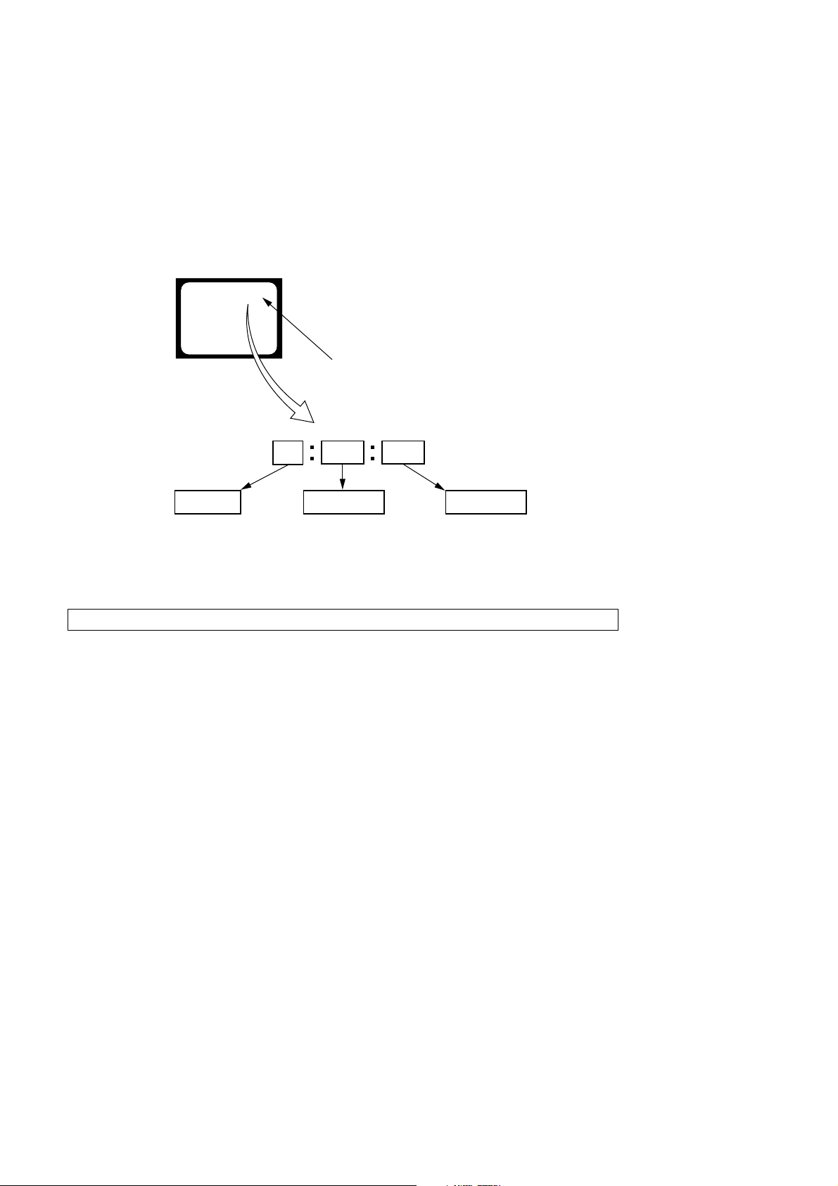
SELF-DIAGNOSIS FUNCTION
1. SELF-DIAGNOSIS FUNCTION
When problems occur while the unit is operating, the self-diagnosis
function starts working, and displays on the viewfinder, or LCD
screen what to do.
Details of the self-diagnosis functions are provided in the Instruction
manual.
Viewfinder or LCD screen
C : 3 1 : 1 1
Blinks at 3.2Hz
1 1
Repaired by:
C : Corrected by customer
H : Corrected by dealer
E : Corrected by service
engineer
3 1C
Block
Indicates the appropriate
step to be taken.
E.g.
31 ....Reload the tape.
32 ....Turn on power again.
2. SELF-DIAGNOSIS DISPLAY
When problems occur while the unit is operating, the counter of the
viewfinder or LCD screen consists of an alphabet and 4-digit number ,
which blinks at 3.2Hz. This 5-character display indicates the
“repaired by:”, “block” in which the problem occurred, and “detailed
code” of the problem.
Detailed Code
Refer to page 6.
Self-diagnosis Code Table.
Note: The self-diagnosis display data will be kept even if the lithium battery (BT591 of FP-959 flexible) is removed.
HDR-FX1/FX1E
— 5 —
Page 6

3. SELF-DIAGNOSIS CODE TABLE
Self-diagnosis Code
Function
Repaired by:
C
C
C
C
C
C
C
C
C
C
C
C
C
C
C
C
C
C
C
C
C
C
C
Block
04
21
22
31
31
31
31
31
31
31
31
31
31
32
32
32
32
32
32
32
32
32
32
Detailed
Code
00
00
00
10
11
20
21
22
23
24
30
40
42
10
11
20
21
22
23
24
30
40
42
Symptom/State
Non-standard battery is used.
Condensation.
Video head is dirty.
LOAD direction. Loading does not
complete within specified time
UNLOAD direction. Loading does not
complete within specified time
T reel side tape slacking when unloading
Winding S reel fault when counting the
rest of tape.
T reel fault.
S reel fault.
T reel fault.
FG fault when starting capstan.
FG fault when starting drum.
FG fault during normal drum operations.
LOAD direction loading motor time-
out.
UNLOAD direction loading motor
time-out.
T reel side tape slacking when
unloading.
Winding S reel fault when counting the
rest of tape.
T reel fault.
S reel fault.
T reel fault.
FG fault when starting capstan.
FG fault when starting drum
FG fault during normal drum
operations
Correction
Use the info LITHIUM battery.
Remove the cassette, and insert it again after one hour.
Clean with the optional cleaning cassette.
Load the tape again, and perform operations from the beginning.
Load the tape again, and perform operations from the beginning.
.
Load the tape again, and perform operations from the beginning.
Load the tape again, and perform operations from the beginning.
Load the tape again, and perform operations from the beginning.
Load the tape again, and perform operations from the beginning.
Load the tape again, and perform operations from the beginning.
Load the tape again, and perform operations from the beginning.
Load the tape again, and perform operations from the beginning.
Load the tape again, and perform operations from the beginning.
Remove the battery or power cable, connect, and perform
operations from the beginning.
Remove the battery or power cable, connect, and perform
operations from the beginning.
Remove the battery or power cable, connect, and perform
operations from the beginning.
Remove the battery or power cable, connect, and perform
operations from the beginning.
Remove the battery or power cable, connect, and perform
operations from the beginning.
Remove the battery or power cable, connect, and perform
operations from the beginning.
Remove the battery or power cable, connect, and perform
operations from the beginning.
Remove the battery or power cable, connect, and perform
operations from the beginning.
Remove the battery or power cable, connect, and perform
operations from the beginning.
Remove the battery or power cable, connect, and perform
operations from the beginning.
Note: Add the sentence as follows.
If other codes are displayed, service is required.
Please send the set to a specialized center.
HDR-FX1/FX1E
— 6 —
Page 7
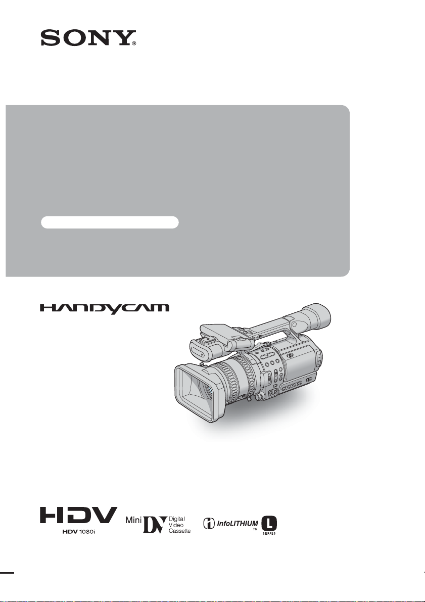
Operating
Instructions
Read this first
Digital HD Video Camera Recorder
2-178-348-11(1)
HDR-FX1
© 2004 Sony Corporation
Page 8
Read this first
Before operating the unit, please read this
manual thoroughl y, and retain it for future
reference.
WARNING
To prevent fire or shock hazard, do no t
expose t h e u nit to rain o r moisture .
This symbol is intended to alert the
user to the pr esence of uninsu late d
“dangerous voltage” within the
product’s enclosure that may be of
sufficient magnitude to constitut e
a risk of electric shock to persons.
This symbol is intended to alert the
user to the presence of important
operating and ma i n te na nce
(servicing) instructions in the
literature accompanying the
appliance.
For customers in the U.S.A. and
CANADA
RECYCLING LITHIUM-ION BATTERIES
Lithium-Ion batter ies are
recyclable.
You can help preserve our
environment by returning your
used rechargeable batteries to the
collection and r ecycling location nearest you.
For more information regarding recycling of
rechargeable batter ies, c al l to ll fr ee 1-800-8228837, or visit http://www.rbrc.org/
Caution: Do not handle damaged or leaking
Lithium-Ion batter ies.
For customers in the U.S.A.
If you have any questions about this product, you
may call:
Sony Customer Information Center 1-800-222SONY (7669)
The number below is for the FCC related matters
only.
Regulatory Information
Declaration of Conformity
Trade Name: SONY
Model No.: HDR-FX1
Responsible Party: Sony Elec tronic s I nc .
Address: 16450 W. Bernardo Dr, San Diego,
CA 92127 U.S.A.
Telephone No.: 858-942-2230
This device complies with Part 15 of the FCC Rules.
Operation is subject to the following two conditions:
(1) This device may not cause harmful interference,
and (2) this device must accep t an y inte r f ere nc e
received, including int erference that may cause
undesired operation.
Owner’s Record
The model and serial nu mb ers are located on the
bottom. Record the serial number in the space
provided below. Refer to these numbers whenever
you call upon your Sony dealer regarding this
product.
Model No. HDR-FX1
Serial No.
Model No.AC-
Serial No.
2
Page 9

CAUTION
You are cautioned tha t any changes or
modifications not expressly approved in this
manual could void your authority to operate this
equipment.
b Note:
• This equipment has been tested and found to comply
with the limits for a Class B digital device, pursuant
to Part 15 of the FCC Rules.
These limits are designed to pr ovide reasonable
protection agains t harmful interference in a
residential installation. This equipment generates,
uses, and can radiate radio fre quen cy en ergy and, if
not installed and used in accorda nc e w ith the
instructions, may cause harmful interference to radio
communications. However, there is no guarantee
that interference will not occur in a particular
installation. If this equipment does cause harmful
interference to radio or television reception, which
can be determined by tu rnin g the eq ui pment off an d
on, the user is encouraged to try to correct the
interference by one or more of the following
measures:
– Reorient or relocate the receiving antenna.
– Increase the separation between the equipment and
receiver.
– Connect the equipment to an outlet on a circuit
different from that into which the receiver is
connected.
– Consult the dealer or an experienced radio/TV
technician for help.
The interface cable supplied must be used with the
equipment in order to comply with the limits fo r a
digital device pursuant to Subpa r t B of Part 15 of
FCC Rules.
Notes on use
Your camcorder is capable of recording in both
HDV and DV formats. You can use only mini DV
cassettes in your camcorder.
The HDV standards
• Digital high-definition (HD) vide o si gna ls are
recorded and played back on a DV format cassette.
• HDV signals are compressed in MPEG2 format,
which is adopted in BS (br oadcast satellite) digit al
and terrestrial digital HDTV broadcastings and in
Blu-ray disc recorders.
Tip
z
• Your camcorder adopts the HDV1080i
specification, which utilizes 1080 effective scanning
lines, within the HDV standards, and records
pictures at the image bit rate of about 25 Mbps. The
i.LINK Interface is adopted as the digital interface
enabling a digital connection with TVs and personal
computers compatible with th e HDV format.
Recording
• Before starting to record, test the recording function
to make sure the picture and sound ar e recor de d
without any problems.
• Compensation for the contents of recordings cannot
be provided, even if recording or playback is not
possible due to a malfunction of the camc or der,
storage med ia, etc.
• TV color systems differ depending on th e country/
region. To view your recordings on a TV, you need
an NTSC system-based TV.
• Television programs, films, video tapes, and other
materials may be copyrighted. Unauthorized
recording of such materials m ay be contrary to the
copyright laws.
The LCD panel, viewfinder, and lens
• The LCD screen and the viewfinder are
manufactured using extremely hi gh- pr e ci sion
technology, so over 99.99% of the pixels are
operational for effec tive use.
However, there may be some tiny black points and /
or bright points (white, red, blue , or gr een in color)
that appear constantly on the LCD scr een a nd the
viewfinder.
These points are norm al results of the ma nufacturing
process and do not affect the recordin g in an y w ay.
• Exposing the LCD screen, the viewfinder, or the lens
to direct sunlight for long periods of time may cause
malfunctions. Be careful when placing the camera
near a window or outdoors.
,continued
3
Page 10
• Do not aim at the sun. Doing so might cause your
camcorder to malfunction. Take pictur e s of the sun
only in low light conditions, such as at dusk .
Playing back HDV tapes on other
devices
A tape recorded in the HDV format cannot be
played back on a d evi ce that is not compatibl e
with the HDV format. The screen appears blue.
Check the conte nt s of tapes by playing them
back on this camcorder prior to playing them
back on other devices.
Connecting other devices
Before connecting your camcorder to other device
such as a VCR or a comp uter with an i.LINK cable ,
be sure to insert the conn ector plug in th e p roper
direction. If you insert the connector plug forcibly
in the wrong direction, the terminal may be
damaged, or this may cause a malfunction of your
camcorder.
Using this manual
The images of the LCD screen and the viewfinder
used on this manual are captured using a digital
still camera, and thus may ap pe ar different from
what you see.
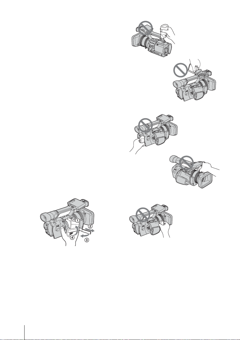
Using the camcorder
• To ensure a good grip, fasten the grip belt as shown
in the following illustra tion.
• Do not hold the camcorder by the following parts.
Viewfinder
LCD panel
Battery pack
Microphone
• You can change the language to be used for screen
display on your camcorder (p. 18).
4
Jack holder
Page 11

Table of Contents
Read this first ............................................................................................. 2
Quick Start Guide
Recording movies ...................................................................................... 8
Getting started
Step 1: Checking supplied items.............................................................. 10
Step 2: Charging the battery pack............................................................ 11
Using an outside power sourc e .................................................................................14
Step 3: Turning the power on................................................................... 14
Step 4: Adjusting the LCD panel and viewfinder...................................... 15
Adjusting the LCD panel ...........................................................................................15
Adjusting the viewfinder .................................................................................. ......... .15
Step 5: Setting the date and time............................................................. 16
Step 6: Inserting a cassette tape.............................................................. 17
Step 7: Setting the screen language........................................................ 18
Recording
Recording movies .................................................................................... 20
Recording for a longer time ................................................................................ 22
Using zoom .............................................................. ................................................. 22
Recording in mirror mode ......................................................................................... 23
Displaying the recording setup in fo r mation – Status check ............................... ....... 24
Adjusting the exposure............................................................................. 25
Adjusting the exposure fo r ba ck l it subjects ........... ............... ..................................... 25
Recording the subject lit by strong light – SPOT LIGHT . .......................................... 25
Adjusting the white balance ......................................................................................26
Recording using manual adjustments...................................................... 27
Adjusting the iris ........................................................................................................ 28
Adjusting the gain .....................................................................................................28
Adjusting the shutter speed ......................................................................................29
Adjusting the volume of light – ND FILTER .............................................................. 30
Displaying the zebra pattern to adjust the brightness ...............................................31
,continued
5
Page 12

Adjusting the focus................................................................................... 32
Adjusting the focus manually .....................................................................................32
Enhancing the outline to focus – PEAKING ..............................................................33
Customizing the picture quality or sound ................................................. 34
Customizing the picture quality – PICTURE PROFILE .............................................34
Adjusting the audio recording level – Microphone volume level ................................36
Recording a picture using various features.............................................. 37
Developing scenes smoothly – Shot transition ..........................................................37
Fading in and out of a scene– FADER ....................................................... .. ..... .... .. ..38
Recording an index signal at the beginning of recording ...........................................39
Recording in 16:9 wide rec mode ....................................................... 40
Reviewing the most recently recorded scenes – Rec Review ................. 41
Playback
Viewing movies ........................................................................................ 42
Playing back in various modes ..................................................................................43
Various playback functions ...................................................................... 44
Searching for the last scene of the most recent recording – END SEARCH .............44
Displaying the screen indicators ................................................................................44
Displaying the date/time and camera settings data – Data code ..............................44
Displaying the video information – Status check .......................................................45
Playing the picture on a TV...................................................................... 46
Viewing the picture on a high definition TV ...............................................................46
Viewing the picture on a 16:9 TV or a 4:3 TV ............................................................48
Locating a scene on a tape for playback.................................................. 49
Searching quickly for a desired scene – Zero set memory ........................................49
Searching for a scene by date of recording – Date search .......................................50
Searching for a recording start point – Index search .................................................50
6
Page 13

Advanced operations
Troubleshooting
Using the Menu
Selecting menu items .........................51
Using the (CAMERA SET) menu
– STDYSHOT TYP/FRAME REC,
etc. ...............................................52
Using the (AUDIO SET) menu
– AUDIO MIX, etc. ........................56
Using the (LCD/VF SET) menu
– LCD COLOR, etc. .....................58
Using the (IN/OUT REC) menu
– REC FORMAT/TV TYPE, etc. ...59
Using the (OTHERS) menu
– CLOCK SET/WORLD TIME,
etc. ...............................................62
Customizing Personal Menu ..............65
Assigning the functions ......................68
Dubbing/Editing
Dubbing to another tape ....................70
Recording pictures from a VCR
or TV ............................................74
Connecting to a computer ..................77
Dubbing sound to a recorded
tape ........................................78
Connecting an analog VCR to the
computer via your camcorde r
– Signal conversion function ........81
Troubleshooting .................................83
Warning indicators and me ss age s .....88
Additional Information
Using your camcorder abroad ............90
HDV format and recording/playback ..91
About the “InfoLITHIUM” battery
pack ..............................................92
About i.LINK .......................................94
Maintenance and precautions ............95
Specification .......................................98
Quick Reference
Identifying parts and controls ...........100
Index ................................................107
Note on the icons used in this manual
: Features available for the HDV
format only.
: Features av ailable for the DV format onl y.
7
Page 14
Quick Start Guide
Recording movies
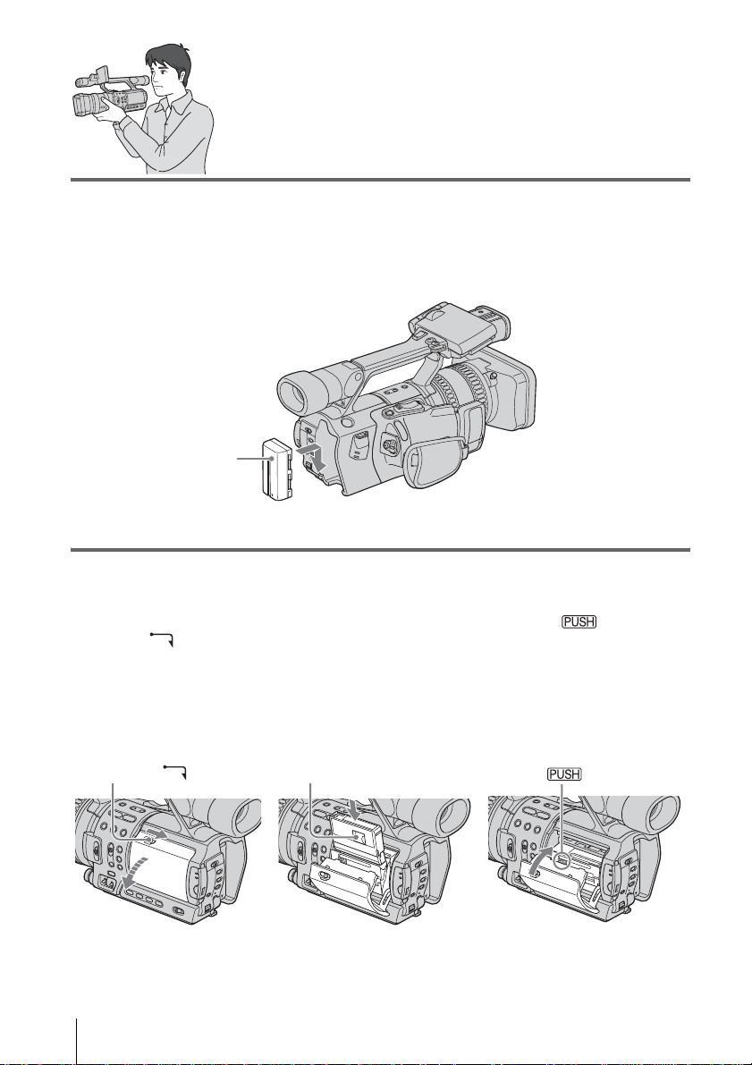
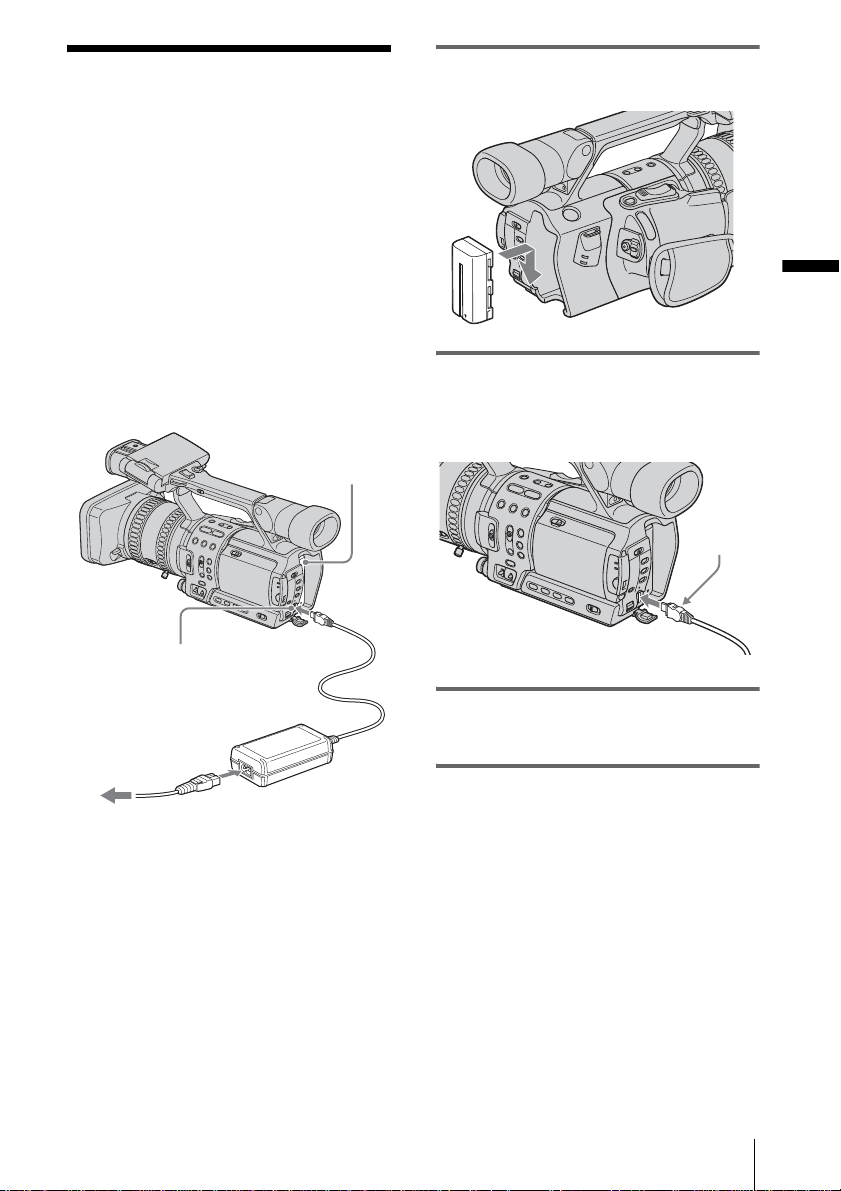
1 Attach the charged battery pack to the camcorder.
To charge the battery, see page 11.
Press the battery pack and slide it down.
Battery Pack
2 Insert a cassette into the camcorder.
a Slide the OPEN/
EJECT lever in
the direction of the
arrow to open the lid.
The cassette compartment
comes out automatically.
OPEN/EJECT lever
Quick Start Guide
8
b Insert the cassette with
its window-side facing
out, then push the center
of the back of the
cassette.
Window-side
c Press on the
cassette
compartment.
Close the cassette lid after
the cassette co m partment
slides back in by itself.
Page 15
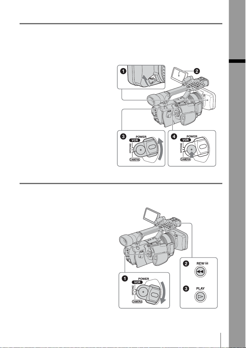
3 Start recording while checking the subject on the LCD screen.
The date and time is not set up in the default setting. To set the date and time, see page16.
The pictures are recorded in the HDV format in t he default setting. To record in the DV format,
see page 60.
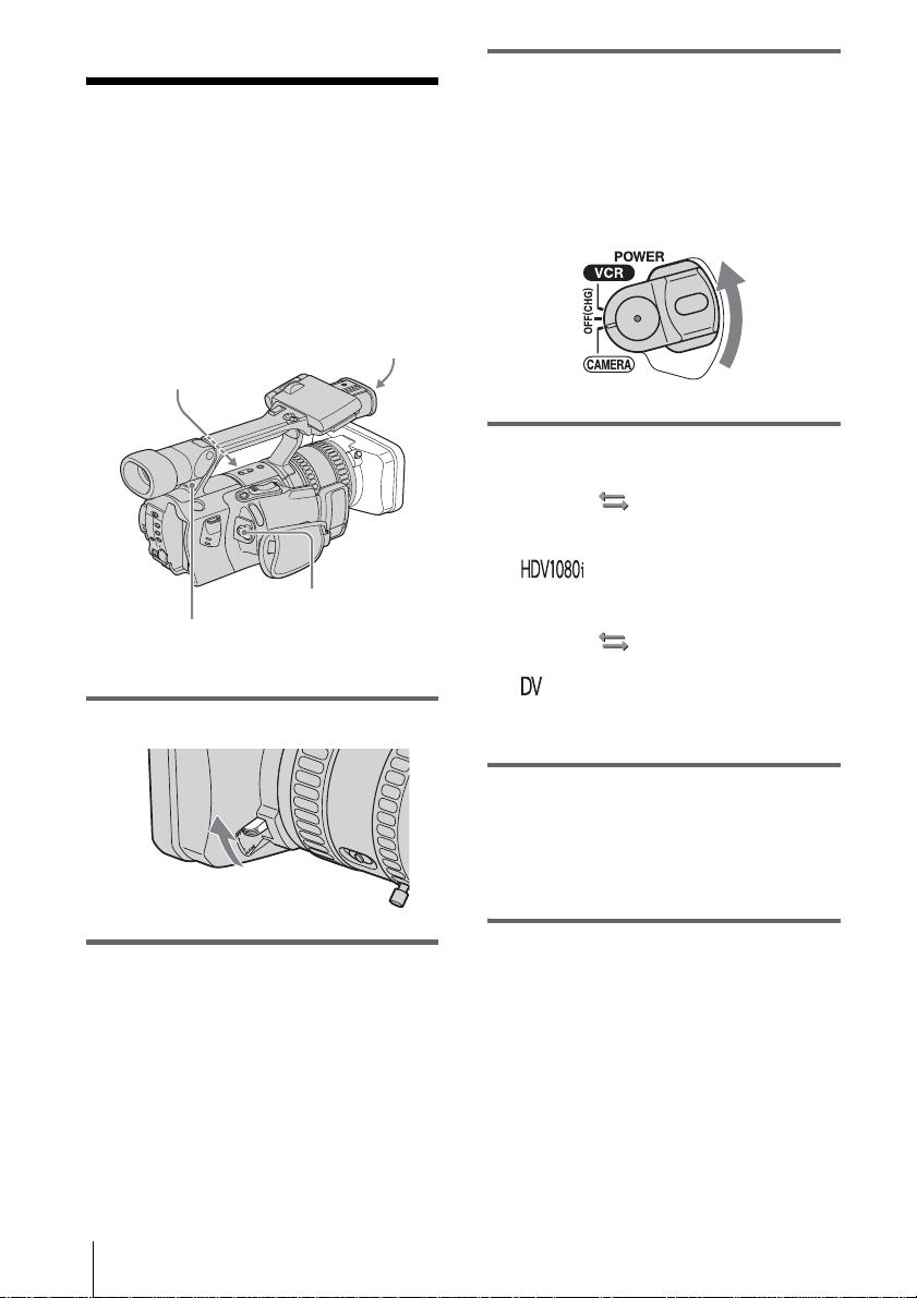
a Open the hood shutter.
b Open the LCD panel and
adjust the angle.
c While pressing the green
button, set the POWER
switch to CAMERA.
d Press REC START/STOP.
Recording starts. To change to
standby mode, pr es s REC
START/STOP again.
4 View the recorded picture on the LCD screen.
Quick Start Guide
a While pressing the green
button, set the POWER
switch to VCR.
b Press m (rewind).
c Press N (play) to start the
playback.
To stop, press x (stop).
To turn off the power, set the POWER
switch to OFF (CHG).
Quick Start Guide
9
Page 16
Getting started
Step 1: Checking
supplied items
Wireless Remote Commander (1)
Make sure you have followi ng items supplied
with your camc order.
The number in pa rentheses indi cates the numbe r
of that item supplied.
AC Adapt or (1)
Power cord (1)
Lens hood (1)
This is attached to your camcorder.
A/V connecting cable (1)
Component video cable (1)
Shoe adaptor (1)
To attach it to your cam corder, see page 104.
Rechargeable battery pa ck NP - F570 (1)
Size AA (R6) batteries (2)
To insert the batteries in the Remote
Commander, see pa ge 105.
Cleaning cassette (1)
b Note
• If you attach an optical filter (optional) or so, remove
the lens hood.
Large eyecup (1)
To attach it to your camcorder, see pag e 16.
Getting started
10
Shoulder strap (1)
To attach it to your cam corder, see page 101.
Operating Instructions (This manual) (1)
Page 17
Step 2: Charging the
battery pack
You can charge the battery by attaching the
“InfoLITHIUM” battery pack (L series) to
your camcorde r .
b Note
• You cannot use batter ie s othe r tha n the
“InfoLITHIUM” battery pack (L series) (p. 92).
• Do not short-circuit the DC plug of the AC Adaptor
with any metallic objects. This may cause a
malfunction.
• Use a nearby wall outlet when using the AC
Adaptor. Disconnect the AC Adaptor from the wall
outlet immediately if a ny ma lf unction occurs.
Battery pack
1 Press the battery pack and slide it
down.
Getting started
2 With the b mark on the DC plug
facing the battery pack, connect the
AC Adaptor to the DC IN jack on your
camcorder.
b mark
DC IN jack
Power cord
To the wall outlet
AC Adaptor
DC plug
3 Connect the power cord to the AC
Adaptor.
4 Connect the power cord to the wall
outlet.
,continued
Getting started
11
Page 18
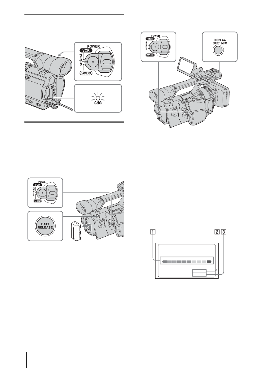
5 Set the POWER switch to OFF (CHG).
The CHG (charg e) lamp lights up and
charging starts.
To check the remaining b attery – Battery
Info
After charging the battery
The CHG (charge) lamp turns off when the
battery is fully charged. Disconnect the AC
Adaptor from the DC IN jack.
To remove the battery pack
Set the POWER switch to OFF (CHG).
1
2 Press BATT RELEASE and slide the
battery pack up.
You can check the battery’s curr ent charge l evel
and its current remaining record in g time both
during charging or when the power is turned off.
The remaining recording time in the selected
recording form at appears.
1 Set the POWER switch to OFF (CHG).
2 Open the LCD panel and adjust the
angle.
3 Pr ess DISPLAY/BATT INFO.
The battery information appears for about
7 seconds.
Keep the butt on pres sed to vi ew it for a bout
20 seconds.
BATTERY INFO
BATTERY CHARGE LEVEL
REC TIME AVAILABLE
LCD SCREEN:
VIEWFI NDER:
A Battery charge level: Displays
approximate remaining amount of
power left in the batt ery pack.
B Possible recording time using the LCD
panel.
C Possible recording time using the
viewfinder.
50%0% 100%
110
min
125 min
Getting started
12
Page 19

Charging time
Approximate number of minutes required when
you fully charge a fully discharged battery pack
at 25°C (77°F). (10 – 30° C (50 – 86°F)
recommended.)
Battery pack
NP-F570 (supplied) 260
NP-F770 370
NP-F970 485
b Note
• NP-F330/F530/500/510/710 battery packs cannot be
used with your camcorder.
Recording time
Approximate nu m ber of minutes availabl e
when you use a full y charged batter y pack at
25°C (77°F).
Recording in the HDV format
Battery pack Continuous
recording
time
NP-F570
(supplied)
NP-F770 235
NP-F970 360
110
125
125
260
255
390
385
Recording in the DV format
Battery pack Continuous
recording
time
NP-F570
(supplied)
NP-F770 255
NP-F970 380
120
130
130
275
275
410
410
Typical
recording
time
60
65
65
130
130
130
200
205
205
Typical
recording
time
65
65
65
140
140
140
210
215
215
• The top figures show an approximate number of
minutes when the LCD BACKLIGHT switch is set
to ON.
• The middle figures show an approximate number of
minutes when the LCD BACKLIGHT switch is set
to OFF.
• The bottom figures show an approximate number of
minutes when recording with the viewfind er.
• “Typical recording time” me ans an approximate
number of minutes when recording while you
repeatedly record, start/stop, move the POWER
switch to change the power mode, and zoom. The
actual battery life may be shorter.
z Tip
• You can also use NP-F550/F730/F750/F960 battery
packs. After charging these battery pa ck s, m ak e a
trial recording with them before an actual recording
to see the recording t ime. The recording time varies
depending on the environment where the camcorder
is used. Press DISPL AY/BATT INFO to disp lay the
recording time on the screen.
Playing time
Approximate number of minutes available
when you use a fully charged battery pack at
25°C (77°F).
HDV format pictures
Battery pack LCD panel
opened*
NP-F570
(supplied)
NP-F770 360 400
NP-F970 545 605
175 195
DV format pictures
Battery pack LCD panel
opened*
NP-F570
(supplied)
NP-F770 415 480
NP-F970 630 725
* With th e LCD BACKLIGHT switch se t to O N .
b Note
• The power will not be supplied from the battery pack
when the AC Adaptor is conn ected to the DC IN ja ck
of your camcorder, even if its power cord is
disconnected from the wall outlet.
• The recording and playback time wil l be shor te r
when you use your camcorder in low temperatur e .
200 235
LCD panel
closed
LCD panel
closed
Getting started
,continued
Getting started
13
Page 20
• The CHG (charge) lamp flashes during charging, or
the battery informat ion w ill not be correctly
displayed in following conditions.
– The ba tte r y pa ck is not attached corr e ctly.
– The batter y pa ck is dam a ge d.
– The batter y pa ck is fully discharged. (For Battery
information only.)
Using an outside power source
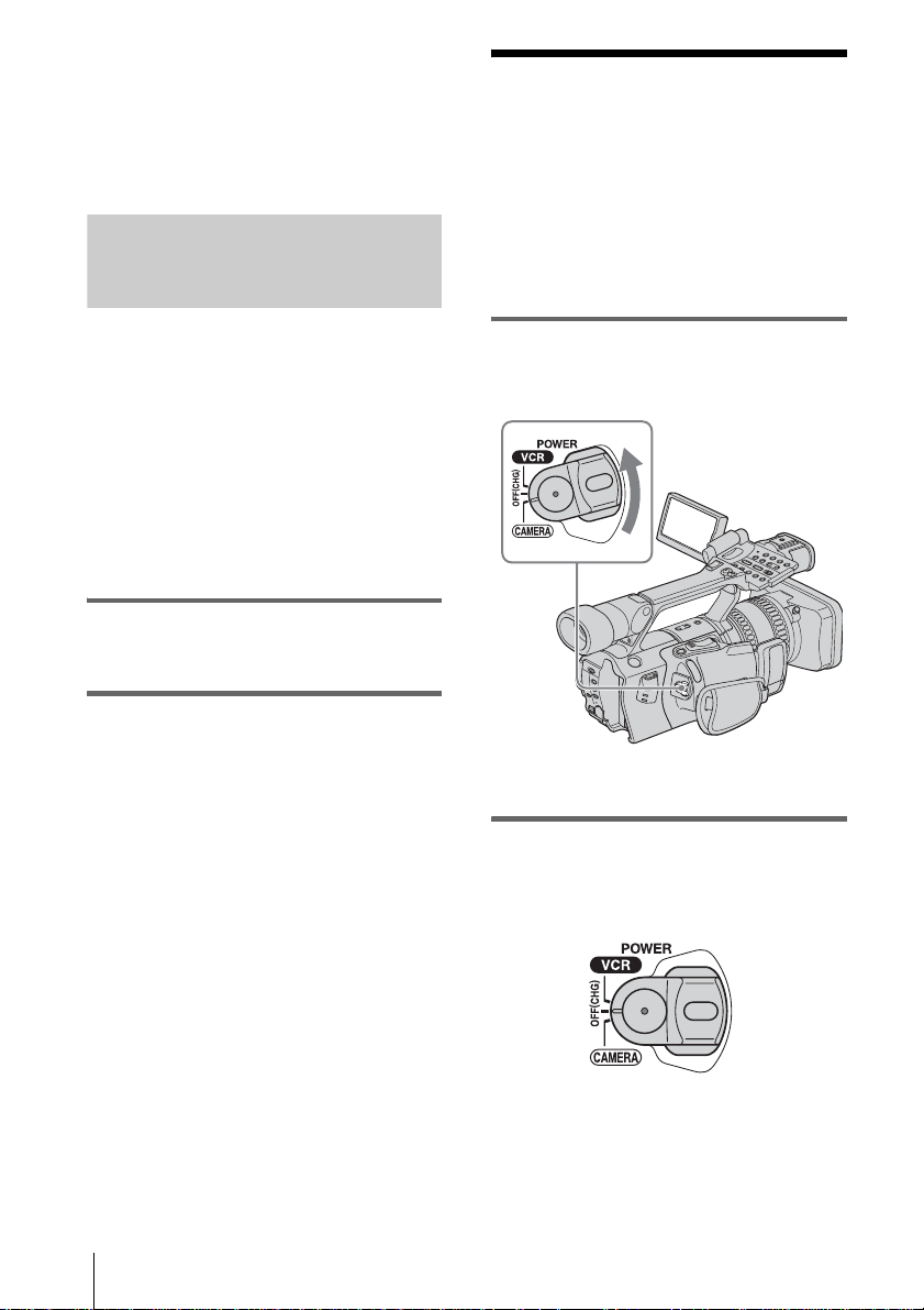
Step 3: Turning the
power on
You need to set the POWER switch to the
respective power mode to record or play back
pictures.
When using this camcorder for the first time,
the [CLOCK SET] screen appears (p. 16).
You can use the AC Adaptor as the power
source when you do not want the battery to
run out. While you are using the AC Adaptor,
the battery pack will not lo se i ts c harge e v en
when it is attached to your cam corder.
PRECAUTION
Even if your camcorder is turned off, AC power
(house current) is still supplied to it while
connected t o the wall outle t via th e AC Adapt or.
Connect your camcorder as shown in
“Step 2: Charging t he battery pack”
(p. 11).
While pressing the green button, set the
POWER switch.
The power turns on.
• CAM ER A : To record pictures.
• VCR: To play or edit picture s.
To turn off the power
Set the POWER switch to OFF (CHG).
Getting started
14
Page 21
Step 4: Adjusting the
LCD panel and
viewfinder
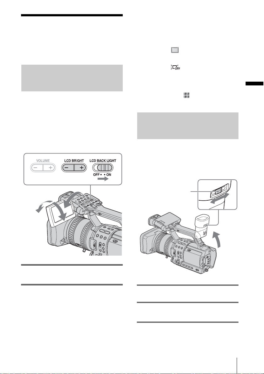
Adjusting the LCD panel
You can adjust the angle and brightness of
the LCD panel to meet various recording
situations.
Even when there are obstruc t ions between
you and the subje ct, you can check the
subject on the LCD screen during recording
by adjusting the angl e of the LCD pa n el.
z Tip
• If you rotate the LCD panel until it faces down, you
can close and restore the LCD panel to the original
position with the LCD screen facing out.
• If you are using the battery pack for power source ,
you can select the brightness by setting [LCD BL
LEVEL] on the [LCD/VF SET] menu
• When you use your camcorder in bright c onditions
using the battery pack, set the LCD BACK LIGHT
switch to OFF ( appears). This position saves
battery power.
• Even if you change the brightness of the LCD panel,
the brightness of recorded pictures is not affected.
• You can turn off the operation confirmation beep by
setting [BEEP] on the (OTHERS) menu to
(p. 62).
[OFF]
(p. 58).
Adjusting the viewfinder
You can view images using the viewfinder
when you close the LCD panel. Use the
viewfinder wh en the batter y is running ou t, or
when the screen is hard to see.
Getting started
Up to about
100 degrees
Open the LCD panel 180 de grees, then
rotate it to the desired position.
180 degrees
To adjust the brightness of the LCD
screen
Adjust the brightness by pressing LCD
BRIGHT – or +.
Viewfinder lens
adjustment lever
1 Lift up the viewfinder.
2 Adjust the viewfinder lens adjustment
lever until the picture is clear.
Getting started
15
Page 22
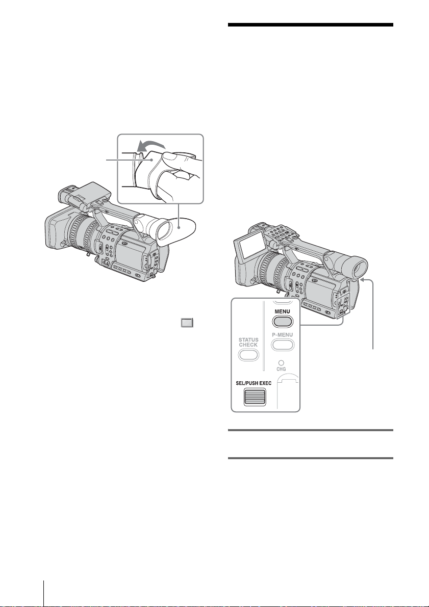
When the picture in the viewfinder is
hard to see
If you cannot see the picture in the viewfinder
clearly under bright circumstances, use the
supplied larg e eyecup.
To attach the large eyecup, stre tch it a l itt le and
align it with the gr oove of the viewfinder, then
slide it up to the end. You can attach the large
eyecup facing either the right or left side.
Step 5: Setting the
date and time
Set the date and time when using this
camcorder for the first time. If you do not set
the date and time, the [CLOCK SET] screen
appears eve ry t im e yo u tur n on your
camcorder.
Large eyecup
(supplied)
z Tip
• To select the brightness of the viewfinder backlight
when you are using the battery pack, select
(LCD/VF SET) menu, then [VF B.LIGHT] (p. 58).
b Note
• If you do not use your camcorder for about 3
months, the built-in rechargeable button-t ype
battery gets discharged and the date and time
settings may be cleared from the memory. In that
case, charge the rechargeable button-type battery
(p. 97) and then set the date and time again.
POWER switch
1 Turn on your camcorder (p. 14).
Getting started
16
2 Open the LCD panel and adjust the
angle.
Proceed to step 6 when you set the clock for
the first time.
Page 23
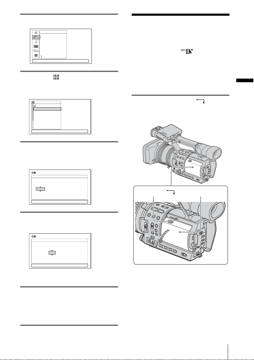
3 Press MENU.
CAMERA SET
WB PRESET
AE RESPONSE
GAIN SETUP
SHOT TRANS
STEADYSHOT
STDYSHOT TYP
FLCKR REDUCE
[MENU]:END
Step 6: Inserting a
cassette tape
You can use mini DV cassettes only.
For details on these cassettes (such as writeprotection), see page 91.
4 Select the (OTHERS) menu by
turning the SEL/PUSH EXEC dial,
then press the dial.
OTHERS
RETURN
ASSIGN BTN
CLOCK SET
WORLD TI ME
LANGUAGE
BEEP
REC LAMP
FORMAT LAMP
[MENU]:END
5 Select [CLOCK SET] by turning the
SEL/PUSH EXEC dial, then press the
dial.
120min
CLOCK SET
AMDMY 12100:JAN2004
[MENU]:CANCEL
6 Set [Y] (year) by turning the SEL/
PUSH EXEC dial, then press the dial.
120min
CLOCK SET
b Note
• Do not force the cassette into the compartment. This
may cause a malfunction of your cam co rd er.
1 Slide the OPEN/EJECT lever in
the direction of the arrow and open the
lid.
OPEN/EJECT lever
Lid
Getting started
AMDMY 12100:JAN2004
[MENU]:CANCEL
You can set any yea r up to the year 2079.
7 Set [M] (month), [D] (day), hour and
minute in the same way as was done in
step 6, then press the dial.
For midnight, set it to 12:00AM.
For midday, set it to 12:00PM.
The cassette compartment automatically
comes out and opens up.
,continued
Getting started
17
Page 24
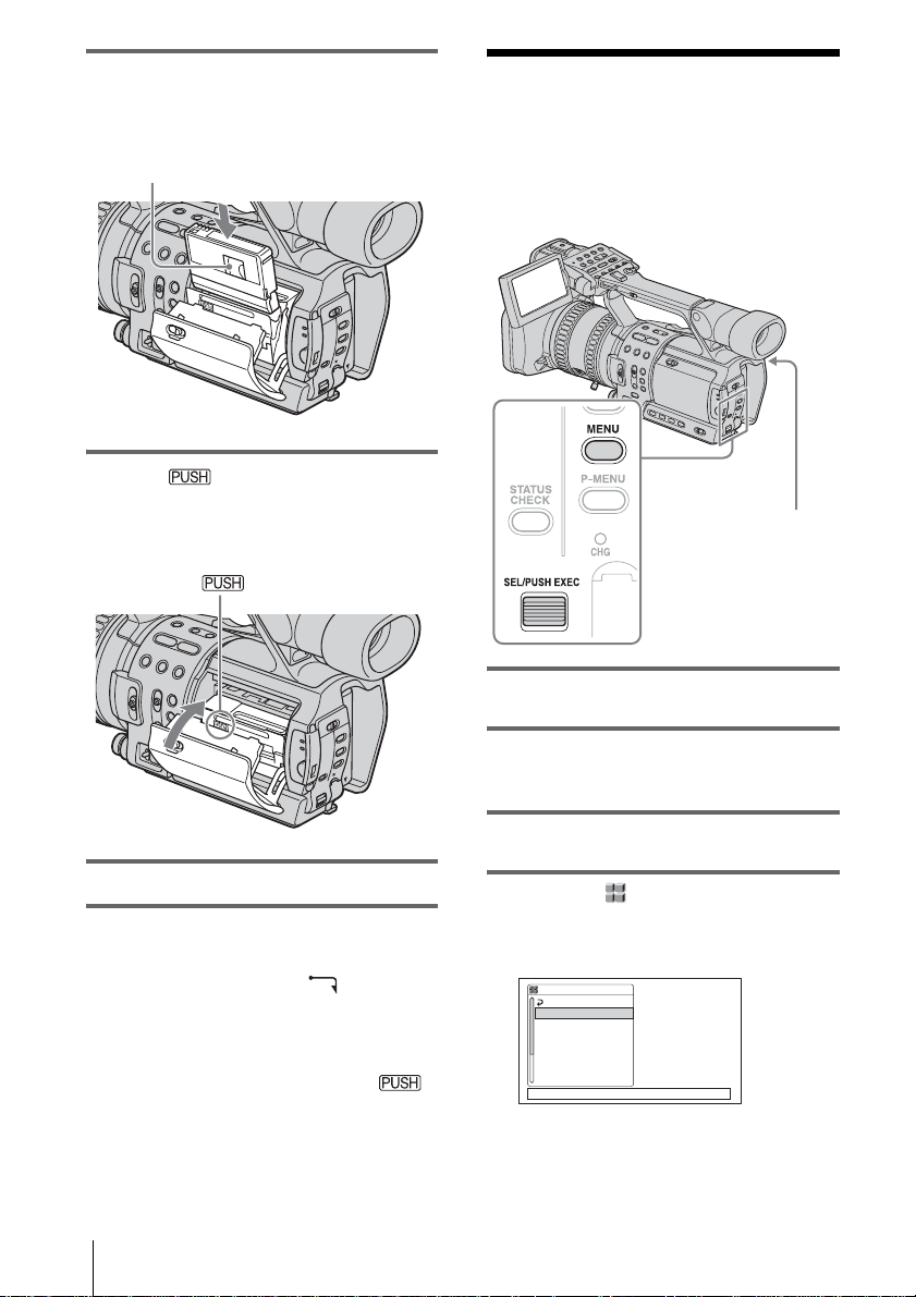
2 Insert a cassette with its window-side
facing out.
Window-side
Push the center of the back
of the cassette lightly.
3 Press on the cassette
compartment.
The cassette compartment automatically
slides back in.
Step 7: Setting the
screen language
You can select the language to be used on the
LCD screen.
POWER switch
1 Turn on your camcorder.
4 Close the lid.
To eject the cassette
Slide the OPEN/EJ E CT lever in the
1
direction of the arrow and open the lid.
The cassette compartment automatically
comes out.
2 T ake out the casset te, then press .
The cassette compartment automatically
slides back in.
3 Close the lid.
Getting started
18
2 Open the LCD panel and adjust the
angle.
3 Press MENU.
4 Select the (OTHERS) menu by
turning the SEL/PUSH EXEC dial,
then press the dial.
OTHERS STBY
RETURN
ASSIGN BTN
CLOCK SET
WORLD TI ME
LANGUAGE
BEEP
REC LAMP
FORMAT LAMP
[MENU]:END
Page 25

5 Select [LANGUAGE] by turning the
SEL/PUSH EXEC dial, then press the
dial.
ENGLISH
[
ENG
SIMP
FRANÇAIS
ESPAÑOL
PORTUGUÊS
0:00:00
]
LANGUAGE
[MENU]:END
6 Select the desir ed lang uage by t urnin g
the SEL/PUSH EXEC dial, then press
the dial.
7 Press MENU to hide the menu screen.
z Tip
• Your camcorder offers [ENG [SIMP]] (simplified
English) for when you cannot find your native
tongue among the options.
Getting started
Getting started
19
Page 26
Recording
Recording movies
You can record movies in either the HDV or
the DV format.
Before recording, follow steps 1 to 7 in
“Getting started” (p. 10 - p. 18).
Movies will be recorded along with stere o
sound.
Camera recording la mp
Format lamps
POWER switch and
Camera recording
lamp
1 Open the shutter of the lens hood.
REC START/STOP
3 While pressing the green button, set
the POWER switch to CAMERA.
The HDV format lamp lights up and your
camcorder is se t t o recording standb y ( the
default setting).
It takes some time f or your camcorder to be
set to recording standby.
4 Select the recording format.
To record in the HDV format
Select the (IN/OUT REC) menu ,
[REC FORMAT], then [HDV1080i] (the
default setting)(p. 60).
appears on the LCD screen and
your camcorder is set to recording standby .
To record in the DV format
Select the (IN/OUT REC) menu ,
[REC FORMAT], then [DV] (p. 60).
appears on the LCD screen, the DV
format lamp lights up, and your camcorder
is set to recording standby.
2 Open the LCD panel and adjust the
angle.
Recording
20
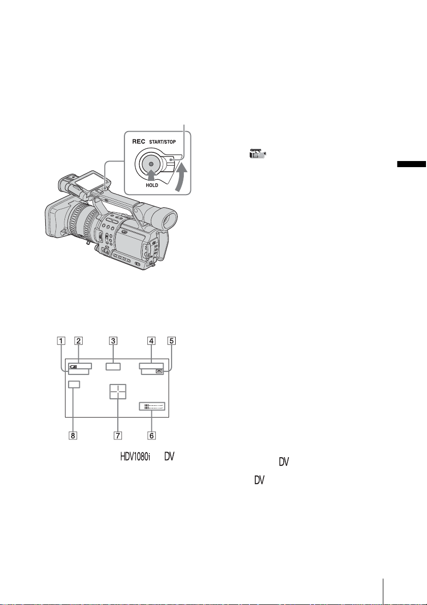
5 Press REC START/STOP.
Recording starts. [REC] appears on the
LCD screen and the Camera recording
lamps light up.
Press REC START/STOP again to stop
recording.
To turn the power off
Set the POWER switch to OFF (CHG).
Page 27
To record from a low-angle
Use the REC START/STO P button on the
handle after releasing the HOLD lever.
To view the picture during recording, face the
LCD panel or the viewfinder upward, or face
the LCD screen down, then clos e and restore the
LCD panel to the original position with t he LCD
screen facing out.
HOLD lever
Indicators displayed during recording
The indicators will not be recorded on the tape.
Date/time and the camera settings data (p. 44)
will not be displayed during recording.
60
min
HDV1080
ND
1
REC
i
A Recording fo rm at ( or )
Recording mo de (SP or LP) is also
displayed in the DV format.
B Remaining battery
The indicated time may not be correct,
depending on the environment where you
are using your cam corder. When you open
or close the LCD pane l, it t akes about
1 minute to display the correct remaining
battery time.
0:00:00
60
min
L
R
C Recording status ( [S TBY ] (standby) or
[REC] (recordin g))
D Time code or tape counte r (h our:
minute: second)
The time code of this camcorder utilizes the
drop-frame s ystem.
E Recording capacity of the tape (p. 64)
F Microphone volume level (p. 36)
G Center marker (p. 55)
The center marker appears at the center of
the screen when [CENTER MARKR] on
the (CAMERA SET) menu is set to
[ON]. It helps composing pictures on the
screen.
H ND filter
If [ND1] or [ND2] flashes on the screen,
activate the ND filter (p. 30).
b Note
• Before changing the battery pack, set the POWER
switch to OFF (CHG).
• When the camcorder is left in recording standby for
more than about 5 minutes, your camcorder exits the
recording standby mode (the drum stops rotating) to
prevent tape wear and battery loss. Sinc e th e power
does not turn off, you can restart recording by
pressing REC START/STOP again. It takes some
time to restart reco r ding, but this not a malfunction.
z Tip
• You can record the color bars on a tape. If you record
movies including the color bars, you can a djust the
color while observing the color bar s whe n you are
viewing the pictures on a TV or monitor. To display
the color bars, press BARS. Press BARS again to
hide the color bars.
• To ensure smooth transition on a tape from the last
recorded scene to the next, note the fo llowing.
– Do not remove the cassette. (The picture will be
recorded continuously without a break even when
you turn the power off).
– Do not record pictures in the HDV format and the
DV format on the same tape.
– Do not record pictures in SP mode and LP mode on
the same tape.
– Avoid st opping then recording a movie in the LP
mode.
• The recording time, date , and the ca m er a se ttings
data are recorded automat ical ly on the tape without
being dis p layed on the scr e en. You can view this
information during playback by pressing DATA
CODE (p. 44).
Recording
,continued
Recording
21
Page 28
• Following functions may not work correctly with the
tape recorded in the HDV format and the DV format
mixed:
– Zero set memory
– Date search
– Index search
Recording for a longer time
On the (IN/OUT REC) menu, select
[ REC MODE], then [LP] (p. 60).
In the LP mode, you can record 1.5 times
longer than you can when record ing in the SP
mode.
A tape recorded in the LP mode should be
played back only on this camcorder.
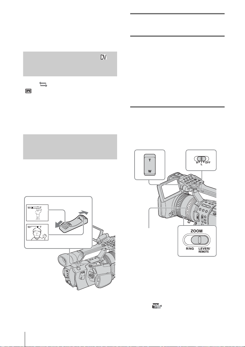
Using zoom
Zoom levers are mounted on the camera itself
and on the handle.
Occasional use of the zoom is effective, but
use it sparingly for the best results.
1 Set the ZOOM switch to LEVER/
REMOTE.
2 Press the power zoom lever slightly for
a slower zoom. Press it further for a
faster zoom.
To record a wider ra nge of view
Press the W side of th e power zoom lever.
The subject appear s farther away (Wide
angle).
To record a closer view
Press the T side of the power zoom lever.
The subject appears closer (Telephoto).
Using the handle zoom
You can adjust the zoom speed with the handle
zoom switch when using the handle zoom lever.
Handle zoom lever
Handle zoom switch
1 cm (approx. 1/2 inch)*
80 cm (approx. 2 5/8 feet)*
* The minimum distance required between your
camcorder and the subject to get a sharp focus with
that side of the le ver.
Recording
22
Zoom ring
1 Set the ZOOM switch to LEVER/
REMOTE.
2 Set the handle zoom switch to H (high) or
L (low).
You can set t he zoom speed of H or L of the
handle zoom lever in [HANDLE ZOOM]
on the (CAMERA SET) menu. In the
default setting, [H] is set t o 6, a nd [L] is se t
to 3 (p. 54).
Page 29
3 Press the handle zoom lever to zoom in or
out.
b Note
• You cannot adjust the zoom spe e d by pres sing the
handle zoom lever. Change the zoom speed by
setting [HANDLE ZOOM] (p. 54).
• You cannot use the handle zoom lever when the
handle zoom swi tc h is set to OFF.
• You cannot change the zoom spe ed of the power
zoom lever on the camera itself by switching the
handle zoom switch.
Using the zoom ring
You can zoom at the desired speed. Fine
adjustment is al so possible.
1 S et the ZOOM switch to RING.
2 R otate the zoom ring to zoom.
b Note
• Rotate the zoom ring at an appr opr ia te spe e d.
Zooming may not be able to catch up the rotating
speed of the ring if it is rotated too fast.
• When you zoom us in g th e Rem ot e Co mma n der , set
the ZOOM switch to LEVER/REMOTE.
• Zoomed position and picture a ngle change wh en the
ZOOM switch is switched from LEVER/REMOTE
to RING.
• If you rotate the zoom r ing fast, motor noise will
become louder as the zoom motor rotates at high
speeds. If the mot or noise is so loud that can be
recorded, use the zoom lever or the Remote
Commander.
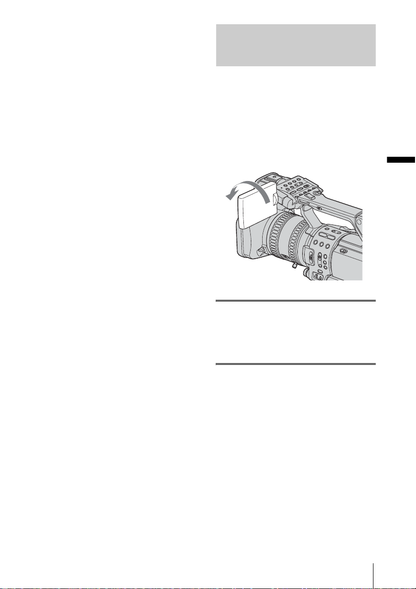
Recording in mirror mode
You can turn the LCD panel towards the
subject so that you and your subject can share
the image being recorded. You can also
utilize this function wh en recording yo urself,
or to keep the attention of small children
attracted to the camcorder while you record
them.
Up to about 100 degrees
Open the LCD panel 180 degrees, then
rotate it towards the subject until it clicks.
A mirror-image of the subject appears on the
LCD screen, but the picture will be normal
when record ed.
Recording
Recording
23
Page 30
Displaying the recording setup
information – Status check
You can check the setup value of the
following items in the standby mode or
during recording.
• Audio setup such as microphone volume level
(p. 36)
• Output setup ([COMPONENT], [i.LINK
CONV], and [TV TYPE] settings) (p. 60)
• Functions assigned to the ASSIGN buttons
(p. 68)
• Pictur e pr ofile setup (p. 34)
b Note
• Information of the picture profile setup does not
appear when it is set to [ O FF].
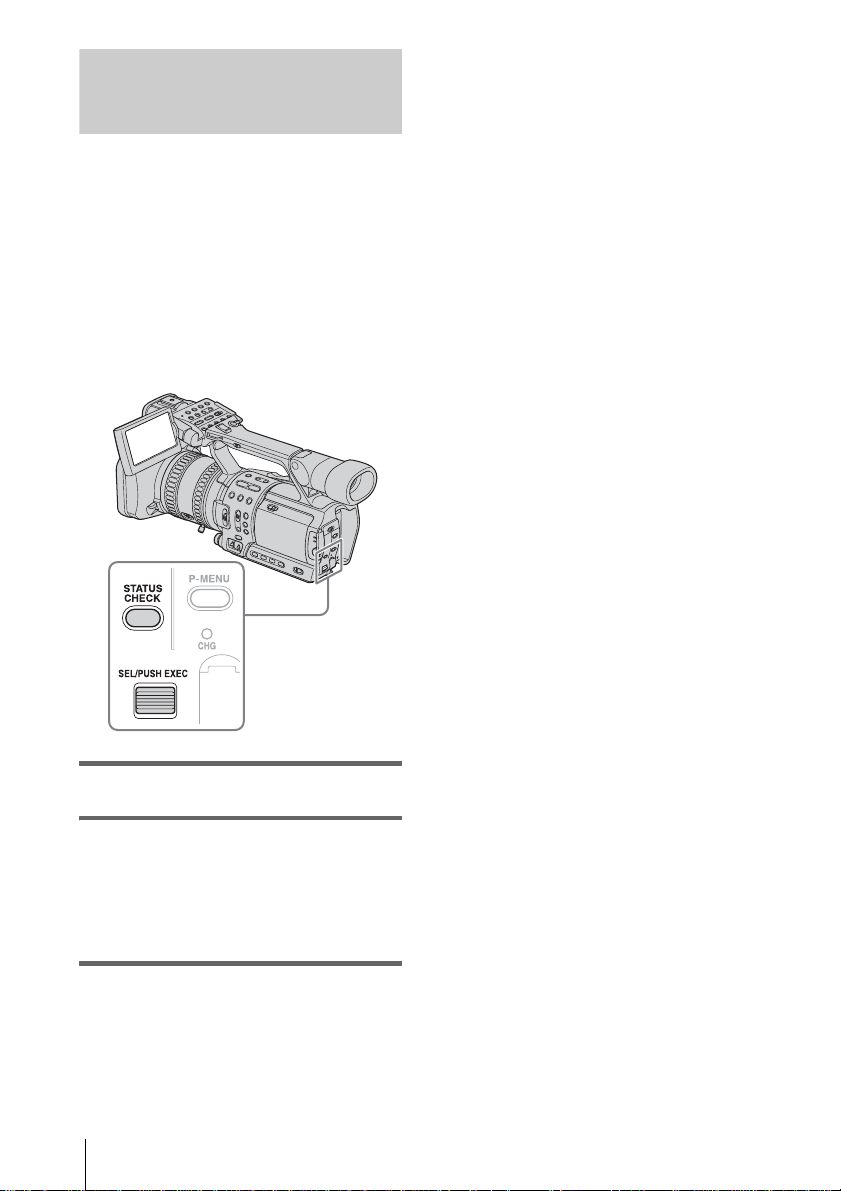
1 Press STATUS CHECK.
2 Turn the SEL/PUSH EXEC dial to
display the desired item.
Each time you turn the dial, the items
appear in the following order:
AUDIO t OUTPUT t ASSIGN t
PICT. PROFILE
To turn off the display of the recording
setup information
Press STATUS CHECK.
Recording
24
Page 31

Adjusting the
exposure
The exposure is adjusted automatically in the
default setting.
If you want to record brighter or darker
pictures than those of the aut o exposure
adjustment, use the manual adjustment
function (p. 27), or customize the picture
quality by using the PICTURE PROFILE
function (p. 34).
Adjusting the exposure for backlit
subjects
When your subject has its back to the sun or
other light, yo u can adjust the exposu re to
prevent the subject from becoming
shadowed.
• You cannot use the back light function if 2 or more
items out of ir is, g ain, an d shutt er speed are ad justed
manually.
Recording the subject lit by
strong light – SPOT LIGHT
When the subject is li t by strong light, such as
in a theater, use the spot light function to
prevent people’s faces from appearing
excessively white.
Recording
Press BACK LIGHT during recording or
in the standby mode.
. appears.
To cancel the back light function, press BACK
LIGHT again.
b Note
• The back light function is canceled when you press
SPOT LIGHT.
During recording or in the standby mode,
press SPOT LIGHT.
appears.
To cancel the spot ligh t fun ct i on, press SPOT
LIGHT again.
b Note
• The spot light function is canceled when you press
BACK LIGHT.
• You cannot use the spot light func tion if 2 or more
items out of ir is, g ain, an d shutt er speed are ad justed
manually.
Recording
25
Page 32

Adjusting the white balance
You can adjust the white balance according
to the light of the recording environment.
The white balance adjustment data for 2
different recording conditions can be set up
and memorized separately in memory A an d
B. During recording, you can recall the setup
data from the memory with the WHT BAL
(white balance) switch. The setup data will be
retained for about 3 months as long as it is not
readjusted even if the power i s di sconnected.
(one-push)
WHT BAL
1 During recording or in the standby
mode, set the AUTO LOCK switch to
the center position to release the auto
lock mode.
2 Press WHT BAL.
3 Set the WHT BAL switch to A or B.
4 Shoot a white subject such as a piece of
paper filling the entire screen under
the same lighting condition as that of
the subject.
5 Press (one-push) WHT BAL.
A or B flashes quickly.
When the white bal ance is adjusted, A
or B lights up and the adjustment data is
memorized.
To recall adjustment data from the
memory
1
During recording or in the standby
mode, set the AUTO LOCK switch to the
center positio n to release the auto lock
mode.
2 Se t the WHT BAL switch to A or B.
3 Pr ess W HT BAL.
The white balance is set to the recalled
adjustment.
b Note
• Avoid subjecting your camco rd er to mech anical
shock while A or B is flashing.
• If A or B does not change from flashing to lit
steadily, your camco rder is unable to set up the wh ite
balance. In this case, use the preset or automatic
white balance.
To use the preset white balance
Your camcorde r has 2 sets of preset whit e
balance values to be selected according to the
light of the recording scene.
1 During recording or in the standby
mode, set the AUTO LOCK switch to the
center positio n to release the auto lock
mode.
2 Pr ess MENU.
3 Select the (CAMERA SET) menu
by turning the SEL/PUSH EXEC dial,
then press the dial .
4 Se lect [WB PRESET] by turning the
SEL/PUSH EXEC dial, the n press the
dial.
5 Select the desire d i te m by turning the
SEL/PUSH EXEC dial, the n press the
dial.
26
Recording
Page 33

Item Recording scene
[OUTDOOR]
()
[INDOOR] (n) • at party or in studios
• general night views,
neon signs, or fireworks
• sunset, sunrise
• under daylight
fluorescent lamps
where lighting
conditions change
quickly
• under video lamps such
as those in a studio, under
sodium lamps, mercury
lamps, or warm white
fluorescent lamps
6 Press MENU to hide the menu screen.
7 Set the WHT BAL switch to PRESET.
8 Press WHT BAL.
The white balance is set to the selected
setting.
To restore the automatic white balance
Press WHT BAL, or se t t he AUTO LOCK
switch to AUTO LOCK.
b Note
• If you set the AUTO LOCK switch to AUTO
LOCK, other manually adj usted items (iris, gain,
shutter speed) al so be come temporarily aut omatic.
Recording using
manual adjustments
You can manually adjust th e iris, gain, etc.
according to the brightness of the recording
scene or in order to obtain desired effects.
Adjust the iris, gain, shutter speed, and white
balance after setting the AUTO LOCK
switch to the center position to release the
auto lock mode.
Depending on the po sition of the AUTO
LOCK switch, you can hold or release the
settings of these functions.
Position Purpose
AUTO LOCK To adjust automaticall y.
Center (to
release the auto
lock mode)
HOLD Select this position after adjusting
See page 26 for details on how to adjust the
white balance.
b Note
• If you want to set the exposure intentionally to other
than a proper level, adjust the iri s, gai n, and shutter
speed manually.
• If you adjust only one of either iris, shutter speed, or
gain manually, you can record with ir is priority,
shutter speed priority, or gain priority, respe c tively.
z Tip
• To adjust the brightness of pictures, set all of the iris,
gain, and shutter speed to the manual adjustment
mode, then rotate the ir is dial.
To adjust manually.
the settings manually to retain
them.
Recording
Recording
27
Page 34

Adjusting the iris
You can manually adjust the light volume
entering the lens.
As the iris is opened (smaller aperture
values), the light volume increases. The
range of focus narrows and only the subject
appears in sharp focus.
As the iris is closed (larger aperture values),
the light volume decreases an d the range of
focus widens.
IRIS dial
To restore automatic adjustment
Press IRIS, or set the AUTO LOCK switch to
AUTO LOCK.
b Note
• If you set the AUTO LOCK switch to AUTO
LOCK, other manually adjusted items (gain, shutter
speed, white balance) also become temporarily
automatic.
• As you shift the zoom from W (wide) to T
(telephoto), the aperture va lu e va ries from F1.6 to
F2.8.
z Tip
• You can select the rotation directio n of th e iris dial
with [IRIS DIAL] on the (OTHERS) menu
(p. 63).
• The iris has an importa nt effect on the “depth of
field,” that is, th e focused range. An open iris makes
the depth of field shallower (s horter focuse d range),
and a closed iris makes the depth of fie ld dee p e r
(longer focused range). Use the iris effectivel y
according to your purpose of recording.
Adjusting the gain
Adjust the gain manually when shooting
blackish or dark objects if you do not want
the AGC (auto gain control) to be activated.
1 During recording or in the standby
mode, set the AUTO LOCK switch to
the center position to release the auto
lock mode.
2 Press IRIS.
The current aperture value (F) appears.
3 Rotate the IRIS dial to a desired
aperture value.
The aperture value (F ) va ries from F1.6 to
F11, and Close, and the cor responding
value appears.
Recording
28
Page 35

1 During recording or in the standby
mode, set the AUTO LOCK switch to
the center position to release the auto
lock mode.
2 Press GAIN.
The current gain value appears.
3 Set the GAIN switch to the desired
position.
3 gain levels (H, M, L) are available.
You can set the value for the respective
positions with [GAIN SETUP] on the
(CAMERA SET) menu (p. 52).
The default settings for each position are
18 dB (H), 9 dB (M) and 0 dB (L).
The larger the num b er, the greater the gai n.
To restore automatic adjustment
Press GAIN, or set the AUTO LOCK switch to
AUTO LOCK.
b Note
• If you set the AUTO LOCK switch to AUTO
LOCK, other manually adj u st ed items (iris, shutter
speed, white balance) also beco me temporarily
automatic.
Adjusting the shutter speed
You can manually adjust and fix the shutter
speed for your conveni e nce. Depending on
the shutter speed, you can make the subject
look still, or on the contrary, emphasize the
fluidity of movement.
Recording
1 During recording or in the standby
mode, set the AUTO LOCK switch to
the center position to release the auto
lock mode.
2 Press SHUTTER SPEED.
3 Adjust the shutter speed by turning
the SEL/PUSH EXEC dial.
You can select a shutter speed between 1/4
second and 1/10000 second.
The selected shutter speed appears on the
screen. For exa m ple, if you select 1/100
second, [100] a ppears. The larger th e
number that appears on the screen , t he
faster the shutter speed. The smaller the
number that appears on the screen , t he
slower the shut te r speed.
,continued
Recording
29
Page 36

To restore automatic adjustment
Press SHUTTER SPEED, or set the AUTO
LOCK s w itch to AU T O LOCK.
b Note
• If you set the AUTO LOCK switch to AUTO
LOCK, other manu ally adjusted items (i ri s, gain,
white balance) also become temporarily automatic.
z Tip
• It is difficult to focus automatically at a lower shutter
speed. Manual focusing with your camcorder
attached to a trip od is recommended.
• The picture may flicker or change colors under
fluorescent lamps, sodium lamps, or mercury lamps.
Adjusting the volume of light
– ND FILTER
You can record the subject cl early by using
the ND filter when the recording
environment is too bright.
There are 2 levels of ND filter setting. ND
filter 1 reduces the volume of light to about
1/6, and ND filter 2 to about 1/32.
If [ND2] flashes
Set the ND FILTER switch to 2 to turn on
[ND2].
If [ND OFF] flashes
Set the ND FILTER switch to OFF to turn off
the indicator.
b Note
• If you move the ND FILTER switch during
recording, the picture and sound may be dis torte d.
• If you adjust the iris manually, no ND filter indicator
will appear even if the ND fi lte r shou ld be activat ed.
z Tip
• If you close the iris extensively when recording a
bright subject, diffraction may occur, resulting in a
fuzzy focus. (This is a common phenome non with
video cameras.) The ND filter suppress es this
phenomenon and gives better recording results.
If [ND1] or [ND2] flashes in the standby
mode, set the ND FILTER switch to the
respectiv e p os i tion.
If [ND1] flashes
Set the ND FILTER switch to 1 to turn on
[ND1].
Recording
30
Page 37

Displaying the zebra pattern to
adjust the brightness
If there is a part of the screen where
brightness is over a certain level, the part may
appear excessively white when played back.
By displaying the zebra pattern on such a
part, you can be reminded to adjust the
brightness before recording.
Select the brightness level to display the
zebra pattern in the menu setting.
Select a value from [70] to [100] or [100+].
If you select [70], the zebra pattern appears
at the part of 70±5 % of th e br i ll i ance
signal.
If you select [100+ ], the zebra pattern
appears at all areas of the brilliance signal
over 100 %.
The default settin g is [100+].
5 Press MENU to hide the menu screen.
6 Set the ZEBRA/PEAKING switch to
ZEBRA.
The zebra pattern wil l appear.
To hide the ze bra pattern
Set the ZEBRA/PEAKING switch to OFF.
b Note
• The zebra pattern is not recorded on the tape.
• You cannot use the zebra pattern when the peak i ng
function is activated (p. 33).
Recording
1 During recording or in the standby
mode, press MENU.
2 Select the (CAMERA SET) menu
by turning the SEL/PUSH EXEC dial,
then press the dial.
3 Select [ZEBRA LEVEL] by turning
the SEL/PUSH EXEC dial, then press
the dial.
4 Select the desired level by turning the
SEL/PUSH EXEC dial, then press the
dial.
Recording
31
Page 38

Adjusting the focus
The focus is adjusted automatically in the
default setting.
1 During recording or in the standby
mode, set the FOCUS switch to MAN
(manual).
9 appears.
Adjusting the focus manually
You can adjust the focus manually according
to the recording conditions.
Use this function in the following cases.
– To record a subject behind a window covered
with raindrops.
– To record horizontal stripes.
– To reco rd a subject with lit tl e contrast
between the subje ct and its background.
– When you w ant to focus on a subject in the
background.
– To reco rd a stationary subj ect using a tripod.
Focus ring
2 Rotate the focus ring and adjust the
focus.
9 changes to when the focus cannot be
adjusted any farther.
when the focus cannot be adjusted any
closer.
Tips for focusing manually
• It is easier to focus on the subject when
you use the zoom function. Move the
power zoom lever towards T (tele ph o t o)
to adjust the focus, and then, towards W
(wide angle) to adjust the zoom for
recording.
• When you want to record a close-up
image of a subject, move the power zoom
lever towards W (wide angle) to fully
magnify the image, then adjust the focus.
To focus on a distant subject
Record the subject with the FOCUS switch sli d
down to INFINITY.
appears.
If you release the switch, it returns to automatic
focusing.
Use this function to record a distant subject
when a close subject is focused using automatic
focusing.
9 changes to
32
To use the expanded focus
Press EXPANDED FOCUS.
[EXPANDED FOCUS] appears and the center
of the screen is magnified by about 2 times. It
will be easier to confirm the focus sett ing during
manual focusing. The screen returns to the
original size after about 5 seconds.
As long as the focus ring is rotated, the image
remains magnified. The image returns to the
original size in ab out 2 seconds after you release
the ring, or when you press REC START/
STOP.
To adjust the focus automatically
Set the FOCUS switch to AUTO.
Recording
Page 39

To focus automatically temporarily
Record the subj ect with PUSH AUT O pressed.
If you release the button, the setting returns to
manual focusing.
Use this function to shift the focus from one
subject to another. The scenes will transition
smoothly.
z Tip
• The focal distance information (for when it is dark
and hard to adjust the focus) appea r s fo r about 3
seconds in the follow ing cases. (It will not be
displayed correctly if you are usi ng a conve r sion
lens (optional).)
– When the focus mode is switched from automatic
to manual.
– When you rotate the focus ring.
Enhancing the outline to focus
– PEAKING
You can enhance the outline of the image on
the screen for easier focusing.
z Tip
• For easier focusing, use peaking tog ethe r wi th the
expanded focus.
Recording
During recording or in standby mode, set
the ZEBRA/PEAKING switch to
PEAKING.
To cancel peaking
Set the ZEBRA/PEAKING switch to OFF.
b Note
• The peaking is not recorded on the tape.
• You cannot use the peaking function when the zebra
pattern is activated (p. 31).
Recording
33
Page 40

Customizing the
picture quality or
sound
Customizing the picture quality
– PICTURE PROFILE
You can customize the picture quality by
adjusting the color intensity, brightness,
white balance, etc. You can set 6 different
picture quality settings depending on the
recording time of day, the weather, or the
camera person, an d store them in the
memory.
Connect your camcorder to a TV or monitor,
and adjust the picture qu ality while observing
the picture on the TV or monitor screen.
At the default setting, [PP1] through [PP6]
are registered with picture quality settings for
the following recording conditions.
Picture profile
number
PP1 Appropriate setting to reco rd in
PP2 Appropriate setting to reco rd in
PP3 Appropriate setting to record
PP4 Appropriate setting to record
PP5 Appropriate setting to record
PP6 Appropriate setting to reco rd in
You can change th e above default setting s a t
your convenie nce.
Recording condition
the HDV format
the DV format
people
film-like pictures
sunset
black and white
1 In the standby mode, press PICTURE
PROFILE.
2 Select a picture profile number by
turning the SEL/PUSH EXEC dial,
then press the dial.
[PP1] through [PP6] are available.
3 Select [SETTING] by turning the SEL/
PUSH EXEC dial, then press the dial.
4 Select an item to be adjusted by
turning the SEL/PUSH EXEC dial,
then press the dial.
5 Adjust the picture quality by turning
the SEL/PUSH EXEC dial, then press
the dial.
Item Adjustment
[COLOR
LEVEL]
[COLOR
PHASE]
[SHARPNESS]
–7 (low) to +7 (high)
–8: black and white
–7 (greenish) to +7 (reddish)
0 (softer) to 15 (clearer)
34
Recording
Page 41

Item Adjustment
[SKINTONE
DTL]
[AE SHIFT] –7 (darker) to +7 (lighter)
[AGC LIMIT] Select the upper limit for the
[AT IRIS
LMT]
[WB SHIFT] –7 (to make white parts
[AWB SENS] To set the auto white balance
[CINEMATONE γ]
To make wrinkles less
noticeable by suppressing the
outlines on the part of skin
color to be enhanced.
[TYPE1] (the color range
recognized as a skin co lor is
narrow) to [TYPE3] (the color
range recognized as a skin
color is wide)
In the case of [TYPE3], the
effect may also be appli ed to a
color that is not a skin color.
[OFF]: no adjustment
gain ([OFF], 12dB, 6dB,
0dB).
[OFF] is 18dB.
Select the highest aperture
value for the automatic
adjustment (F11, F6. 8, F4).
bluish) to +7 (to make white
parts reddish)
operation under a reddish light
source such as an
incandescent lamp or candle,
or under a blueish light source
such as in outdoor shade.
[HIGH] (reddishness or
blueishness is reduced) to
[LOW] (reddishness or
blueishness is increased)
[AWB SENS] is not effective
under a clear sky or the sun.
[ON]: Pictures are recorded
with the gamma curve that
reproduces the natural
gradation sequence, similar to
that of film cameras.
Item Adjustment
[CINEFRAME]
[COPY] To copy a picture profile
[RESET] To restore the default setting
[CINEFRAME 30]:
Pictures are recorded with a
cinema-like atmosph ere. This
produces the feel of
smoothness better than
[CINEFRAME 24].
[CINEFRAME 24]:
Pictures are record ed with the
atmosphere of 24 frames per
second adopted by film
recording.
[OFF]: normal recording
setting to other picture
profiles.
of the picture profile.
6 Repeat steps 4 and 5 to adjust other
items.
7 Select [ RETURN] by turning the
SEL/PUSH EXEC dial, then press the
dial.
8 Select [OK] by turning the SEL/PUSH
EXEC dial, then press the dial.
A picture profile in di cator appears.
To cancel the picture profile recording
Select [OFF] in step 2 , then press the SEL/
PUSH EXEC dial.
To check the picture profile settings
During recording or in the standby mode, press
STATUS CHECK (p. 24).
To copy the picture profile setting to
other picture profiles
1
Press PICTURE PROFILE.
2 Select the number of the picture profile
to be copied from by turni ng t he SEL/
PUSH EXEC dial, then press the dial.
3 Se lect [S ETTI NG] by turnin g the SEL/
PUSH EXEC dial, then press the dial.
Recording
,continued
Recording
35
Page 42

4 Select [COPY] by turning the SEL/
PUSH EXEC dial, then press the dial.
5 Sel ect the number of th e pi cture profile
to be copied to by turn ing the SE L/PUSH
EXEC dial, then press the dial.
6 Select [YES] again by turning the SEL/
PUSH EXEC dial, then press the dial.
If you decide not to copy the s ettings, select
[NO].
7 Pre ss PIC TURE PROFILE.
To reset the picture profile settings
You can reset the pi ct ure profile setting s by
picture profile number. You cannot res et all
picture profile set t ings at once.
1 Pre ss PIC TURE PROFILE.
2 Sel ect the number of th e pi cture profile
to be reset by tu rning the SE L/PUSH
EXEC dial, then press the dial.
3 S el ect [SETTIN G] by turning the SEL/
PUSH EXEC dial, then press the dial.
4 Sele ct [RES ET] by turn ing t he SE L/
PUSH EXEC dial, then press the dial.
5 Select [YES] by turning the SEL/PUSH
EXEC dial, then press the dial.
If you decide not to reset the picture profile,
select [NO].
6 Pre ss PIC TURE PROFILE.
b Note
• If you adjust all of the iris, shut te r sp eed a nd ga in
manually, you cannot obtain the effect of [AE
SHIFT].
• If you adjust the iris manually, you cannot obtain the
effect of [AT IRIS LMT].
• If the object is so bright that the aperture value set in
[AT IRIS LMT] is not appropriate, the shutter speed
may reach 1/2000 automatica lly.
• If you adjust the gain manually, you c an not obtain
the effect of [AGC LIMIT].
• If you select [CINEFRAME 24] when the shutte r
speed is slower than 1/30, the shutt er spe e d is
automatically set to 1/60.
• If you select [CINEFRAME 30] when the shutte r
speed is slower than 1/15, the shutt er spe e d is
automatically set to 1/30.
Adjusting the audio recording
level – Microphone volume level
You can adjust the microphone volume when
recording. Checking the volum e with
headphones is recommended.
1 Open the cover and set the AUTO/
MAN switch to MAN.
The audio level meter appears.
2 During recording or in the standby
mode, adjust the volume by turning
the AUDIO LEVEL dial.
To restore automatic adjustment
Set the AUTO/MAN switch to AUTO.
b Note
• You cannot adjust the volume of au dio input from
the AUDIO/VIDEO jack or the HDV/DV jack.
z Tip
• To check the audio setting info rmation in greater
detail, press STATUS CHECK (p. 24). You can also
check the microphone volume during automatic
adjustment.
36
Recording
Page 43

Recording a picture
using various
features
Developing scenes smoothly
– Shot transition
You can register the settings of focus, zoom,
iris, gain, shutter speed, and white balance,
and then change the recording set ting from
the current one to the registered one, resulting
in a smooth transition of scenes (Shot
transition).
For example, you can shift the focus from
closer objects to farther objects, or change the
depth of field by adjusting the iris. In
addition, you can develop scenes under
different recording conditions smoothly. If
you register the manual adjustment function
of the white balance, the scenes will de velop
smoothly betwe e n objects indoor and those
outdoor.
Use a tripod to avoid camera-shake.
SHOT A
REC
START/STOP
Step 1: Store the settings
1
Press STORE/CHECK/EXEC
repeatedly to turn on the STORE lamp .
2 Adjust the desired items manually.
To adjust the camera setu p items such as iris
manually, set the AUTO LOCK switch to
the center position to release the auto lock
mode. See pages 26 to 29 for details on
adjustment.
3 Press a button (A or B ) t o select the
storage location.
The setting is stored in the selected button.
The settings are cal le d Shot A and Shot B
respectively.
b Note
• If you set the POWER switch to OFF (CHG), the
settings stored in Shot A and B are deleted.
Recording
SHOT B
Set the transition curv e and duration using
[SHOT TRANS] on the (CAMERA
SET) menu (p. 53 ).
Step 2: Check the stored settings (Shot)
1
Press STORE/CHECK/EXEC
repeatedly to turn on the CHECK la mp.
2 Press the button (A or B) in which the
setting was s tored.
The selected sett i ng w i l l t ake effect on the
picture on the screen. The focus, zoom, and
so on, are automatically adjusted as st ored
in the setting.
b Note
• You cannot check the transition time and curve set
using [SHOT TRANS] on the (CAMERA
SET) menu.
,continued
Recording
37
Page 44

Recording using the Shot transition
function
1
Press STORE/CHECK/EXEC
repeatedly to turn on the EXEC lam p.
2 Press REC START/STOP.
3 Press the button (A or B) in which the
desired setting w as stored.
Pictures will be recorded with the settings
that were changed automatically from the
current ones to the stored ones.
Fading in and out of a scene
– FADER
You can add the following effects to
currently recording pictures.
Assign the FADER function to one of the
ASSIGN buttons in advance. See page 68 for
details on how to assign a function.
SHOT TRANS EXEC
b Note
• You cannot zoom, focus, or adjust ma nua l ly while
checking or activating the Shot transition.
• When you change [SHOT TRANS] on the
(CAMERA SET) menu, turn off the STORE/
CHECK/EXEC lamp by pressing the button.
• You cannot return from the stored Shot A or B
settings to previous settings after you activate the
Shot transition during record i ng.
• If you press the following buttons dur ing the shot
transition operation, the operation is canceled:
–PICTURE PROFILE
–MENU
–P-MENU
– EXPANDED FOCUS
– STATUS CHECK
z Tip
• You can record using both settings by making them
change either from Shot A to Shot B or from Shot B
to Shot A. For example, to change from Shot A to
Shot B, turn on the CH ECK lamp and press A
followed by REC START/STOP, then turn on the
EXEC lamp and press B.
• You can rehearse th e s h o t t ran s ition by pressing the
button (A or B), in which the desired setting wa s
stored, before pressing REC START/STOP in step
2.
REC 0:00:05120min
SHOT A
SHOT B
ES
Transition bar
S: start
E: end
To cancel the operation
Press STORE/CHECK/EXEC repeatedly until
the STORE/CHECK/EXEC lamps are all
turned off.
REC START/STOP
[BLACK FADER]
[WHITE FADER]
1 Press the ASSIGN button assigned to
the FADER function in the standby
mode (to fade in) or during recording
(to fade out).
Each time you press the button, the
indicator changes as follows:
[BLACK FAD ER] t [WHITE FADER]
t no display
38
Recording
Page 45

2 Press REC START/STOP.
The FADER indicator stops flashing and
disappears when the fade is complete.
To cancel the operation
Press the ASSIGN button assigned to the
FADER function repeatedly until the FADER
indicators disappear.
b Note
• You cannot use the FADER func tion together with
[FRAME REC] (Frame recording).
Recording an index signal at the
beginning of recording
If you make an index f or a sc e ne , you can
easily search for the scene later (p. 50).
The index function will make it easier to
check the transition of recording or edit your
pictures using index signals.
Assign the index function to one of the
ASSIGN buttons in advance. See page 68 to
assign a function.
Press the ASSIGN button assigned to the
index function.
When pressed during recording
appears for about 7 seconds and an index
signal is recorded.
When pressed in the standby mode
flashes.
After you press REC START/STOP to start
recording, appears for about 7 seconds and
an index signal is recorded.
Recording
To cancel the operation
Before starting to record, press the ASSIGN
button assigned to the index function again.
b Note
• You cannot record an index signal on a recorded tape
afterward.
REC START/STOP
Recording
39
Page 46

Recording in 16:9
wide rec mode
You can display pictures recorded in the DV
format on the entire TV screen by setting
[DV WIDE REC] on the (CAMERA
SET) menu at the time of recording.
Refer to the operating instructions supplied
with your TV as well.
[ON]
Select [ON] to view the recorded pictures on a
16:9 wide TV screen.
On the LCD sc reen or vi ewfin der sc reen
* The playback picture may look different depending
on the TV connected.
On a 4:3 TV screen*
On a 16:9 wide TV
screen
[OFF]
Select [OFF] to view th e re cord ed pic tur es on a
4:3 TV screen.
On the LCD screen or viewfinder screen
The dark bars are
translucent on the screen.
On a 4:3 TV screen
On a 16:9 wide TV
screen*
1 In the standby mode, press MENU.
2 Select the (CAMERA SET) menu
by turning the SEL/PUSH EXEC dial ,
then press the dial.
3 Select [DV WIDE REC] by turning the
SEL/PUSH EXEC dial, then press the
dial.
4 Select [ON] or [OFF ] depending on the
TV, then press the SEL/PUSH EXEC
dial.
5 Press MENU to hide the menu screen.
40
Recording
Page 47

Reviewing the most
recently recorded
scenes – Rec Review
You can view a few seconds of the scene
recorded just before you stopped the tape .
In the standby mode, press REC
REVIEW.
The last few seco nds of the most recen tly
recorded scen e are played back. Then , your
camcorder is set to the standby mode.
Recording
Recording
41
Page 48

Playback
Viewing movies
3 Press m (rewind) to go to the point
you want to view.
Make sure you have a reco r ded cassette
inserted into your camcorder.
Some of the operations are possible using the
Remote Commander.
When you want to play back recordings on
your TV, see page 46.
When playing back the tape, select the
(IN/OUT REC) menu, [VCR HDV/DV],
then [AUTO] (the default setting).
POWER switch
4 Press N (play) to start playback.
To adjust the volume
Adjust the volum e by pressing VOLUM E
– (decrease) / + (increase).
To stop playback
Press x (stop).
To pause
Press X (pau se) during playback.
Press N (play) or X (pause) again to restart the
playback.
Playback stops au to m at ically when the pause
mode continues for more than 5 minutes.
To fast forward or rewind
Press M (fast forward) or m (rewind) in stop
mode.
To review movies on the viewfinder
Close the LCD panel. Then, adjust the
viewfinder ang le .
Indicators displayed during tape
playback
1 Open the LCD panel and adjust the
angle.
2 While pressing the green button, set
the POWER switch to VCR.
Playback
42
min
HDV1080
i
A Format of the play back signal
(HDV1080i or DV) / Recording mode (SP
or LP)
B Remaining battery
C Tape transport indicator
D Time code (hour: minu te: second: fra me)
or tape counter (hour: minute: second)
The time code of this camcorder is of the
drop-frame system.
0:00:00:0060
60
min
Page 49

b Note
• When playing back a tape recorded in the HDV and
DV formats, and the signal switches between HDV
and DV, the picture and sound disappear
temporarily.
• You cannot play back the tape recorded in the HDV
format on video cameras of the DV format or miniDV players.
• Recording mode (SP or LP) appears when a tape
recorded in the DV format is played back.
Playing back in various modes
To fast forward or rewind during
playback – Picture search
Keep on pressing M (fast forward) or m
(rewind) during playback.
To resume normal playback, release the button.
To view the picture while fast
forwarding or rewinding – Skip scan
Keep on pressing M (fast forward) or m
(rewind) while fast forwarding or rewinding the
tape.
To resume fast forwar ding or rewinding, r elease
the button.
To Press
play back frame
by frame
To return to the normal playback mode, press N
(play).
* Horizontal lines may appear at the top, bottom, or in
the center of the scree n. Th is is not a malfunction.
b Note
• Pictures in the HDV format are not output from the
HDV/DV jack when they are paused or played
back in other than normal playback mode.
• Pictures in the HDV format may appear distorted
during:
– Picture search
– Reverse playback
C (frame) on the Remote
Commander during playback
pause.
To reverse direction, press c
(frame) on the Remote
Commander during playback
pause.
Playback
To play back in various modes
You will not hear the recorded sound. Also, you
may see mosaic-like images of the previously
played picture r em aining on the screen.
To Press
change the
playback
direction*
play back slowly y (slow) during playback.
play back 2 times
faster (double
speed)
I (reverse) on the Remote
Commander during playback.
To reverse direction
1 Press I (reverse) on the
Remote Commander.
2 y (slow).
×2 (double speed) on the
Remote Commander during
playback.
To reverse direction
1 Press I (reverse) on the
Remote Commander.
2 ×2 (double speed) on the
Remote Commander.
Playback
43
Page 50

Various playback
functions
b Note
• The END SEARCH function will not work correctly
when there is a blank section between recorded
sections on the tape.
You can locate the end of the l a st recording,
or display the date of recording and camera
settings data.
Searching for the las t scene of the
most recent recording
– END SEARCH
This function is hand y when you hav e played
back the tape, for example, but wan t to start
recording right after the most recently
recorded scene. The END SEARCH function
will not work once you eject the cassette after
you have recorded on the tape.
Displaying the screen indicators
You can choose to display the tim e code, tape
counter, and other information on the screen.
Press DISPALY/BATT INFO.
The indicato r switche s on or off as y ou press th e
button.
z Tip
• You can display the screen indicators during
playback on a TV. Select the (OTHERS) menu,
[DISP OUTPUT], then [V-OUT/PANEL] (p. 64).
However, only playback mode indica tor s a nd ta pe
counter appear when playi ng back a tape re corded in
the HDV format, and [COMPONENT] on the
(IN/OUT REC) menu is set to [1080i/480i].
Displaying the date/time and
camera settings data – Data code
During playback, you can vi ew the date /time
data and the camera settings dat a that are
automatically recorded while recording
pictures on a tape.
1 Set the POWER switch to VCR.
2 Press END SEARCH (VCR).
The last scene of the most recent recording
is played back for about 5 seconds.
To cancel the operation
Press END SEARCH (VCR).
Playback
44
1 Set the POWER switch to VCR.
2 Press DATA CODE on the camcorder
or Remote Commander during
playback or playback pause.
Each time you press the button, the
indicators appear in turn as follows:
Date/time t Camera settings da ta t (no
display)
Page 51

Camera settings data display
In the date/time data display, the date and time
is displayed in the same area.
If you record the picture without setting the
clock, [--- -- ----] and [--:--:--] will appear.
60
min
HDV1080
i
AUTO
F1.7 1006
A SteadyShot off
B Exposure
C Aperture value
If you manually adjust the aperture valu e to
the maximum, appears.
D Gain
E Shutter speed
F White balance
appears when pict ures recorded by
using the sh ot transi tion func tion are p layed
back.
0:00:00
60
min
dB
Displaying the video information
– Status check
You can check the setup value of the
following items.
• Audi o setup such as audio mix (p. 56)
• Output signal setup ([VCR HDV/DV], etc.)
(p. 59)
• Functions assigned to the ASSIGN buttons
(p. 68)
Playback
To hide the camera settings data
Select the (OTHERS) menu, [DATA
CODE] then [DATE] (p. 63).
Each time you press DATA CODE, the date/
time indicator turns on and off.
1 Press STATUS CHECK.
2 Turn the SEL/PUSH EXEC dial to
display the desired item.
Each time you turn the dial, the items
appear in the following order:
AUIDO t OUTPUT t ASSIGN
To turn off the video information
Press STATUS CHECK.
Playback
45
Page 52

Playing the picture on
a TV
Viewing the picture on a high definition TV
TV connections differ depending on the type
of TV.
Connect the supplied AC Adaptor to the wall
outlet for the power supply (p. 14).
Refer also to the instruction manuals supplied
with the devices to be conne cted.
To copy to another tape, see page 70.
When you have an S video jack
on your TV or VCR
S video cable
(optional)
A/V connecting
cable (supplied)
Component video cable (supplied)
i.LINK cable (optional)
Signal flow
Connect your camcorder and your TV
using either cables described below.
To connect the TV using an i.LINK cable
This connection is recommended when your TV
is compatible with HDV/DV and has an i.LINK
jack.
• Before connecting the i.LINK cable, select the
(IN/OUT REC) menu, [VCR HDV/DV],
then [AUTO] (the default setting).
TV
Yellow
White
Red
Green
Blue
Red
• In case of this connection, the TV needs to be
set so that it recognizes that the camcorder is
connected. Refer to th e operating manual
supplied with the TV for the details.
To connect the TV using the component
video cable
• To view the picture recorded in the HDV
format, set [COMPONENT] on the (IN/
OUT REC) menu according to your TV
(p. 60). When the picture recorded in the DV
46
Playback
Page 53

format is played back, an equivalent signal
with [480i] is outp ut, even if [1080i/480i] is
selected.
• O nl y vi deo signals are outp ut fr om the
COMPONENT OUTPUT jack. To output
audio signals, connect the white and red plugs
of the A/V conn ecti ng cable t o the audio in put
jack of your TV.
To connect the TV using the A/V
connecting cable
When there is an S video jack on the device to
be connected, connect it with your camcorder
by the S video jacks using an S video cable
(optional) instead of the yellow video plug of
the A/V connecting cable (supplied) . This
connection p roduces pictur es more fai thfull y on
the TV conne cte d. The audi o w il l no t b e o utpu t
when you connect with the S video cable alone.
b Note
• Be sure that you set [VCR HDV/DV] before
connecting the i.LINK cable. Otherwise, the TV
might not be able to recognize the video signal
correctly.
• Pictures in the DV fo rmat are not output from the
COMPONENT OUT ja ck, if copyri ght protecti on
signals are recorded in the pictures .
z Tip
• If you connect your camcorder to you r TV using
more than one type of cables to ou tput the pictures in
analog signal, the output signals have priority in the
following order:
COMPONENT OUTPUT jack t S video jack t
AUDIO/VIDEO jack
• See page 94 for details on i.LINK.
Playback
When your TV is connected to a VCR
Connect your camcorder to the LINE IN input
on the VCR using the A/V connecting cable. Set
the input selector on the VCR to LINE.
Playback
47
Page 54

Viewing the picture on a 16:9 TV or a 4:3 TV
When you have an S video jack
on your TV or VCR
S video cable
(optional)
A/V connecting
cable (supplied)
Component video cable (supplied)
Signal flow
Connect your camcorder and your TV or
VCR using either cables described below.
To connect the TV using the component
video cable
This connection is recommended when your TV
has COMPONENT VIDEO jacks.
• To view the picture recorded in the HDV
format, set [COMPONENT] on the (IN/
OUT REC) menu acco rding to your TV
(p. 60). When a picture recorded in the DV
format is played back, an equivalent signal
with [480i] is output, even if [1080i/480i] is
selected.
• Only video signals are output from the
COMPONENT OUTPUT jack. To output
audio signals, connect the white and red plugs
of the A/V connecting cable to the audio in put
jack of your TV or VCR.
TV or VCR
Yellow
White
Red
Green
Blue
Red
To connect the TV using the A/V
connecting cable
When there is an S video jack on the device to
be connected, connect it with your camc or der
by the S video jacks usi ng an S video cable
(optional) instead of the yellow video plug of
the A/V connecti ng cable (supplied). U s e an S
video cable to produce high resolution pictures.
The audio will not be output when you connect
with the S video cable alone.
To view the picture on a 4:3 TV
• To view the picture recorded in the HDV
format, select the (IN/OUT REC) menu,
[TV TYPE], then [4:3] (p. 61).
• To view the picture recorded in the DV
format, select the (CAMERA SET)
menu, [DV WIDE REC], then [OFF] before
recording (p. 40).
48
Playback
Page 55

When your TV is connected to a VCR
Connect your camcorder to the LINE IN input
on the VCR using the A/V connecting cable. Set
the input selector on the VCR to LINE.
When your TV is monaural (When your
TV has only one audio input jack)
Connect the yellow plug of the A/V connecting
cable to the video input jack and connect the
white or the red plug to the audio input jack of
your TV or VCR.
When you want to p la y t he s ound in monaural
mode, use a connecting cable (optional) for that
purpose.
b Note
• Pictures in the DV fo rmat are not output from the
COMPONENT OUT ja ck, if copyri ght protecti on
signals are recorded in the pictures .
Locating a scene on a
tape for playback
Searching quickly for a desired
scene – Zero set memory
Playback
1 During playback, press ZERO SET
MEMORY on your camcorder or
Remote Commander at the point you
want to locate later on.
The tape counter is reset t o “0:00:00” and
appears on the screen.
If the tape counte r is not displayed, press
DISPALY/BATT INFO.
2 Press x (stop) when you want to stop
playback.
3 Press m (rewind).
The tape stops automatically when the ta pe
counter reache s “0:00:00.”
4 Press N (play).
The playback starts fro m th e point
designated “0:00:00” on the tape counter.
,continued
Playback
49
Page 56

To cancel the operation
Press ZERO SET MEMORY again.
b Note
• There may be a discrepancy of several sec onds
between the time code and the tape counter.
• Zero set memory will no t function corre ctly if there
is a blank section betwee n r ecor d e d se ctions on the
tape.
• The Date search will not function correctly when
there is a blank section between recorded sections on
the tape.
Searching for a recording start
point – Index search
Searching for a scene by date of
recording – Date search
You can locate the point where the recording
date changes.
SEARCH MODE
. / >
STOP
1 Set the POWER switch to VCR.
2 Press SEARCH MODE on the Remote
Commander repeatedly to select
[DATE SEARCH].
3 Press . (previous)/> (next) on
the Remote Commander to select a
recording date.
You can select the previous or the next date
of the present point o n th e t ape.
Playback starts automatically from the
point where the date changes.
To cancel the operation
Press STOP on the Remote Commander.
b Note
• If 1 day’s recording is less than 2 minutes, your
camcorder may not accurately find the point where
the recording date changes.
You can locate the point wher e an index
signal is recorded (p. 39).
SEARCH MODE
. / >
STOP
1 Set the POWER switch to VCR.
2 Press SEARCH MODE on the Remote
Commander repeatedly to select
[INDEX SEARCH].
3 Press . (previous)/> (next) on
the Remote Commander to select an
index point.
You can select the pr evious or the next
index signal of the present point on the tape.
Playback starts automatically from the
point where the index signal is recorded.
To cancel the operation
Press STOP on the Remote Commander.
b Note
• If 1 day’s recording is less than 2 minutes, your
camcorder may not accurately fin d the index point.
• The Index search will not function co rre c tly when
there is a blank section between recorded sections on
the tape.
50
Playback
Page 57

B
Advanced operations
Using the Menu
Selecting menu items
You can change various settings or make
detailed adjustments using the menu items
displayed on the screen.
IN/OUT REC (p. 59)
OTHERS (p. 62)
OTHERS STBY
RETURN
ASSIGN BTN
CLOCK SET
WORLD TI ME
LANGUAGE
BEEP
REC LAMP
FORMAT LAMP
[MENU]:END
4 Select the desired item by turning the
SEL/PUSH EXEC dial, then press the
dial.
The available menu i t em s var y de pending
on the power mode of your camcorder.
Unavailable items will be grayed out.
POWER switch
1 Turn on the power (p. 14).
2 Press MENU to display the menu
index screen.
CAMERA SET
WB PRESET
AE RESPONSE
GAIN SETUP
SHOT TRANS
STEADYSHOT
STDYSHOT TYP
FLCKR REDUCE
[MENU]:END
STBY
3 Select the icon of the desired menu by
turning the SEL/PUSH EXEC dial,
then press the dial.
CAMERA SET (p. 52)
AUDIO SET (p. 56)
LCD/VF SET (p. 58 )
[MENU]:END
STBY
REMOTE CTRL
ON
OFF
0:00:00120min
5 Select the desired setting by turning
the SEL/PUSH EXEC dial, then press
the dial.
OTHERS STBY
BEEP
REC LAMP
FORMAT LAMP
IRIS DIAL
LETTER SIZE
REMAINING
DISP OUTPUT
REMOTE CTRL
[MENU]:END
OFF
6 Press MENU to hide the menu screen.
To return to the previous screen, select
[ RETURN].
Using the Menu
Using the Menu
51
Page 58

Using the
(CAMERA SET) menu
– STDYSHOT TY P/FRAME REC, etc.
You can select the items listed below on the
CAMERA SET men u . For deta ils on how to
select items, see “Selecting menu items”
(p. 51).
The default settings are marked with G. The
indicators in parentheses appear when the
WB PRESET
Select to use the pre set white balance. Se e page 26 for details.
AE RESPONSE
Select the speed to adjust the exposure automatically, in accordance with the
brightness of the subject. [FAST], [MIDDLE], and [SLOW] are available.
GAIN SETUP
Select the adjustment value for each position (H, M, and L) of the GAIN switch
(p. 28).
1 Select [H], [M], or [L ] by turning the SEL/PUSH EXEC dial, the n press
the dial.
2 S elect an adjustment value by turning the SEL/PUSH EXEC dial, then
press the dial.
0dB, 3dB, 6dB, 9dB, 12dB, 15dB, and 18dB are availab l e. The larger the
number, the greater the gain.
3 Select [OK] by turning the SEL/PUSH EXEC dial, then press the dial.
4 Press MENU to hide the menu screen.
setting is selected. The settings you can adjust
vary depending on the power mode of your
camcorder. The screen shows the items you can
operate at the moment. Unavailable items will
be grayed out.
CAMERA SET STBY
RETURN
WB PRESET
AE RESPONSE
GAIN SETUP
SHOT TRANS
STEADYSHOT
STDYSHOT TYP
FLCKR REDUCE
[MENU]:END
OUTDOOR
Using the Menu
52
Page 59

SHOT TRANS
TRANS TIME
TRANS CURVE
Select this setting to set the transition duration and time. See page 37 for details
on using the shot transition function.
Select the time that takes to make a transition from the current setting to the
selected se tting.
Duration from [2.0 sec] through [15.0 sec] are available. It is set to [4.0 sec] in the
default setting.
Select the transition curve.
The figures belo w show the transitio n curve of each mode.
*1: parameter l evel
*2: transition of time
LINEAR Select to make the transition linearly.
GSOFT STOP Select to make the transition slowly at the end.
*1
*2
*1
Using the Menu
*2
SOFT TRANS Select to make the transition slowly at the
beginning and end, and linearly in between.
b Note
• Before setting [SHO T T RANS], turn off all of the S T O R E /CHECK/EXEC lamps by
pressing the button repeatedly (p . 37).
*1
*2
,continued
Using the Menu
53
Page 60

STEADYSHOT
STDYSHOT TYP
GON Select to activate the SteadyShot function. You can select the type of
the SteadyShot function in [STDYSHOT TYP].
OFF ( ) Select to deactivate the SteadyShot fun ct ion . Sel ect whe n r ecor di ng
using a tripod. More natura l pic tures are produced.
You can also deactivate the Steady Shot function by using the
ASSIGN button assigned to the SteadyShot function (p. 68).
b Note
• The SteadyShot function does not work well when a wide conversion lens other than VCL-
HG0872 (optional) is attached to your camcorder.
• When using VCL-HG0872, select [WIDE CONV.] in [STDYSHOT TYP] below.
You can select the t ype of the SteadyShot f unction that compens at es for camerashake. To release the SteadyShot function, select [OFF] in [STEADYSHOT] or
use the ASSIGN bu tt on assigned to the Ste adyShot function (p. 68).
HARD Select to activate the SteadyShot function with stronger effect. This
mode is not recommended for reco rd ing with camera panning
technique.
GSTANDARD Select to activate the standard SteadyShot function.
SOFT Select to act ivate the SteadyShot function so that it le a v e s a sl ight
unsteadiness on the picture so the picture looks natural.
WIDE CONV. Select when a wide conversion lens (optional) is attached. This mode
is the most effective with Sony VCL-HG087 2 w ide con ve rs ion lens.
FLCKR REDUCE
HANDLE ZOOM
Using the Menu
54
GON Select to record under normal c ondi tions. Flickering of the screen
under a light source such as fluorescen t lamp s wil l be reduced.
OFF Select when you do not want to reduce flickering of the screen.
b Note
• Flickering may not be reduced depe nding on the light source.
Select this item to set the zoom speed of position H and L of the handle zoom
switch (p. 22).
1 S elect [H] or [L] by turning the SEL/PUSH EXEC dial, then press the
dial.
2 Select a zoom speed by turn ing the SEL/PUSH EXEC di al, th en pres s the
dial.
Page 61

ZEBRA LEVEL
CENTER MARKR
FRAME REC
Speeds 1 through 8 are available. The larger the number, the faster the zoom
speed.
3 Select [OK] by turning the SEL/ PUSH EXEC dial, then press the dial.
4 Press MENU to hide the menu screen.
See page 31 for details .
GOFF Select when you do not want to display th e center marker on the
screen (p. 21).
ON Select to display the ce nter marker on the screen.
b Note
• The center marker and its position do not affect the adjustment, setting, or recording in any
way.
You can record pictures with a stop-motion animated effect by alternately
recording a few f rames and then movi ng the subject a little . Op erate your
camcorder using the Remote Commander to prevent camera shake.
GOFF Select to record in the standard recording mode.
ON ( ) Select to record pictures using the FRAME REC function.
1 Select [ON], then press the dial.
2 Press MENU to hide the menu screen.
3 Press REC START/STOP.
A picture (approximately 6 frames) is recorded, and your
camcorder enters the standby mo de.
4 Move the subject and repeat step 3.
Using the Menu
DV WIDE REC
b Note
• When you use frame recording continuously, the remaining tape time will not be indicated
correctly.
• The last scene will be longer than other scenes.
• You cannot record index signals during frame recording.
See page 40 for details .
Using the Menu
55
Page 62

Using the (AUDIO
SET) menu
You can select the items listed below on the
AUDIO SET menu. For details on how to select
items, see “Selecting menu items” (p.51).
The default settings are marked with G. The
indicators in parentheses appear when the
setting is selected. The settings you can adjust
MULTI-SOUND
– AUDIO MIX, etc.
You can select how to pl ay bac k audio on a tape that was re corded in st ereo mode
using anothe r camcorder.
GSTEREO Sele c t to pla y ba c k a ster e o tap e or dua l sound track tape with both
main and sub sound.
1 Select to play back a stereo tape with the l eft channel sound or a du a l
sound track tape with the main sound.
2 Select to play back a stereo tape with the right channel sound or a dual
sound track tape with the sub sound.
b Note
• You can play back a dual sound track cas se tte on thi s camcorder. However, you cannot
record a dual sound track on this cam c or de r.
• The setting returns to [STEREO] when you disconnect the power source from your
camcorder for more than 5 minutes.
vary depending on the power mode of your
camcorder. The screen shows the items you can
operate at the moment. Unavailable items will
be grayed out.
AUDI O SET
RETURN
MULTI–SOUND
AUDI O MIX
AUDI O MODE
WIND
MIC/LINE IN
[MENU]:END
STEREO
AUDIO MIX
AUDIO MODE
Using the Menu
56
You can adjust the audio balance betw een the originally rec or d ed sound (ST1)
and sound added af t er w ards (ST2) on the tape (p. 79).
b Note
• You cannot adjust sound recorded in 16 bit audio mode.
• Only the originally recorded sound will be heard when you disconnect the power source
from your camcorder for more than 5 minutes.
G12BIT Select to record in the 12-bit mode (2 ste r e o sounds).
16BIT ( ) Select to record in the 16-bit mode (1 stereo sound with high quality).
b Note
• When recording in the HDV format, sound is automatically recorded in [16BIT] mode.
Page 63

WIND
MIC/LINE IN
GON Standard setting.
OFF Select when you want to record the sound as it is without reducing the
noise caused by wind.
GEXT MIC Select to input an audio signal when a microphone is connected to the
MIC/LINE ja c k .
LINE Select to input an audio signal when an audio device is connecte d to
the MIC/LINE jack.
Using the Menu
Using the Menu
57
Page 64

Using the (LCD/VF
SET) menu
You can select the items listed below on the
LCD/VF SET menu. For details on how to
select items, see “Selecting menu items”
(p. 51).
The default settings are marked with G. The
settings you can adj ust vary depending on the
LCD COLOR
– LCD COLOR, etc.
Turn the SEL/PUSH EX EC dial to adjust the co lo r on the LCD screen. The
recorded pictur e w i ll not be affected by this setting.
power mode of your camcorder. The screen
shows the items you can operate at the moment .
Unavailable item s w ill be grayed out.
LCD/VF SET
RETURN
LCD COLOR
LCD BL LEVEL
VF B. LIGHT
[MENU]:END
LCD BL LEVEL
VF B.LIGHT
Low intensity
High intensity
You can adjust the brightness of the LCD screen’s backlight. The recorded picture
will not be affected by this setting.
GNORMAL Standard brightness.
BRIGHT Select to brighten the LCD screen.
b Note
• When you connect your camcorder to outs ide powe r so urces, [BRIGHT] is automatically
selected for this setting.
You can adjust the brightness of the viewfinder. The recorded picture will not be
affected by this setting.
GNORMAL S ta nda r d brightness.
BRIGHT To brighten the viewfinder screen.
b Note
• When you connect your camcorder to outs ide powe r so urces, [BRIGHT] is automatically
selected for this setting.
Using the Menu
58
Page 65

Using the (IN/OUT
REC) menu
TYPE, etc.
You can select the items listed below on the IN/
OUT REC menu. For details on how to select
these items, see “Selecti ng menu ite ms” (p . 51).
The default settings are marked with G. The
indicators in parentheses appear when the
VCR HDV/DV
– REC FORMAT/TV
Select the playback signal. Normally sel ect [AUTO].
When the camcorder is connected to another device using an i.LINK cable, select
the signal to be input/output from the HDV/DV jack. The selected signal is
recorded or played back.
GAUTO • Sele c t thi s to pla y ba ck signa ls by switching the format between
HDV and DV automatically.
• For an i.LINK connection, selec t this to record/play back signals
input/output from the HDV/DV jack by switching the format
between HDV and DV automatically.
HDV • Select this to play back the signals in the HDV format only.
• For an i.LINK connection, selec t this to record/play back the input/
output signals in the HDV format only.
Select this when connecting the camcorder to a computer, etc.
(p. 77).
DV • Select this to play back the signals in the DV format only.
• For an i.LINK connection, selec t this to record/play back the input/
output signals in the DV format only.
Select this when connecting the camcorder to a computer, etc.
(p. 77).
setting is selected. The settings you can adjust
vary depending on th e power mode of your
camcorder. The scree n shows the it ems you ca n
operate at the mom ent . U n available items wi ll
be grayed out.
IN/OUT REC
RETURN
VCR HDV/DV
REC MODE
COMPONENT
i . LI NK CONV
TV TYPE
A/V DV OUT
[MENU]:END
AUTO
Using the Menu
b Note
• Disconnect the i.LINK cable before setting [VCR HDV/DV]. Otherwise, the connected TV
may not be able to recognize the video sig nal from this camcorder.
• When [AUTO] is selected and the signal switches between HDV and DV, the picture and
sound disappear tempor aril y.
• When [i.LINK CONV] is set to [ON], pictures are output as follows:
– at [AUTO], an HDV signal is converted to the DV format and output; a DV signal is
output as it is.
– at [HDV], an HDV signal is converted to the DV format and output; a DV signal is not
output.
– at [DV ] , a DV signal is output as it is; an HDV signa l is not output.
,continued
Using the Menu
59
Page 66

REC FORMAT
Selects a recording format when the POWER switch is set at CAMERA. The
format lamp of the selected format will light up during recording.
GHDV1080i
()
DV ( ) Select to recor d in the DV format.
z Tip
• When you output the picture during recording simultaneously to a connected device using
an i.LINK cable, also set [i.LINK CONV] accordingly (p. 60).
REC MODE
GSP ( SP ) Select to record in the SP (Standard Play) mode on a tape.
LP ( LP ) Select to increase the recording time to 1.5 times that of the SP mode
b Note
• You cannot add sound on a tape recorded in the LP mode.
• If you record in the LP mode, a random square noise may appear or sound may be
interrupted when you play back the tape on othe r ca mco rde r s or VCRs .
• When you mix recordings in the SP mode and in the LP mode on one tape, the playback
picture may be distorted or the time code may not be written properly between the scenes.
Select to record in the HDV1080i specification.
(Long Play). The use of Sony Excellence/Master mini DV cassettes is
recommended to get the most out of your c am c or der.
COMPONENT
i.LINK CONV
Using the Menu
60
480i Select when connecting you r camcorder to a TV with the com p onen t
input jack.
G1080i/480i Select when connecting your camcorder to a TV that has the
component input jack and is capab le of di spla ying the 1080i signal.
When the POWER switch is set to CAMERA, this se tting is effective only when
[HDV1080i] is selected in [REC FORMAT].
When the POWER switch is set to VCR, this setting is effective only when
[AUTO] or [HDV] is selected in [VCR HDV/DV].
GOFF Select to output the pictures from the HDV/DV jack in accordance
with the [REC FORMAT] and [VCR HDV/DV] settings.
ON (HDVcDV) Select to always output the pictures in the DV forma t fr om the
HDV/DV jack.
b Note
• See [VCR HDV/DV] for information about an input signal via an i.LINK connection.
Page 67

TV TYPE
• Disconnect the i.LINK cable before setting [i.LINK CONV]. Otherwise, the connected
video device may not be able to recogn iz e the vide o signa l from this camcorder.
You need to convert t he s ignal depending on the TV connected.
G16:9 Select to view your pictures on a 16:9 wide TV.
The recorded pictures will appear as follow s :
When HDV pic tures
are played back
When DV pictures
are played back
A/V c DV OUT
4:3 Select to view your pictures on a 4:3 standard TV.
z Tip
• When you view pictures recorded with [DV WIDE REC] on the (CAMERA SET)
menu set to [ON] on a 4:3 standard TV, pictures may appear as they are in height, but are
compressed in width depending on the TV. If you view the recorded pictures on such type
of 4:3 standard TV, set [DV WIDE REC] to [OFF] before recording.
The recorded pictures will appear as follow s :
When HDV pic tures
are played back
When DV pictures
are played back
You can connect a digital device and an analog device to your camcorder and
convert the signal transmitted from the connected devices to the appropriate signal
on your camcor der.
GOFF Select when you are not using the Signal conversion function.
ON ( ) To output analog images and sound in digital f orma t usi ng your
camcorder.
The analog signal input to the AUDIO/VIDEO jack of your camcorder
will be converted and output from the i.LINK Interface of your
camcorder.
For details, see page 81.
Using the Menu
Using the Menu
61
Page 68

Using the (OTHERS)
menu
etc.
You can select the items listed below on the
OTHERS menu. For details on how to select
these items, see “Selecting menu items” (p. 51).
The default settings are marked with G. The
indicators in parentheses appear when the
ASSIGN BTN
CLOCK SET
WORLD TIME
– CLOCK SET/WORLD TIME,
You can assign functions to the ASS IGN buttons (p. 68).
You can set the dat e and time (p. 16).
You can adjust th e t im e difference when using your camc or der abroad. Set the
time difference by tu rning the SEL/PUSH EXEC dial, the clock will be adjusted
in accordance with the time difference. If you set the time difference to 0, the
clock returns to the originally set time.
setting is selected. The settings you can adjust
vary depending on the power mode of your
camcorder. The screen shows the items you can
operate at the moment. Unavailable items will
be grayed out.
OTHERS
RETURN
ASSIGN BTN
CLOCK SET
WORLD TI ME
LANGUAGE
BEEP
FORMAT LAMP
DATA CODE
[MENU]:END
LANGUAGE
BEEP
Using the Menu
62
You can select or change the language used for the on-screen display (p. 18). You
can select from English, Simplified English, Canadian-French, Latin American
Spanish, Brazilian-Portuguese, Traditional-Chinese, or Korean.
GMELODY Select to play a melody when you start/stop recording, or when an
unusual condition occurs on your camcorder.
NORMAL Select to sound a beep instead of the melody.
OFF Select to cancel the melody, the beep sound, and the shutter sound.
Page 69

REC LAMP
FORMAT LAMP
IRIS DIAL
GON Select to turn on the camera recordin g lamps on the front and rear of
your camcorder during recording.
OFF Select this settin g in th e f o llowing recording si tuations. The camera
recording lamps on the front and rea r wi ll not light up during
recording.
• When you do not want the subject to be ner vous about being
recorded.
• When you are recording close to the subject.
• When the subject reflects the light of the recording lamp.
GON Select to turn on the format lamp. The lamp of the form a t tha t is
selected in [REC FORMAT] lights up when the POWER switch is set
to CAMERA. The lamp of the format that is selected in [VCR HDV/
DV] lights up when th e P O WER switch is set to VCR.
OFF Select when you do not want to turn on the format lamp. The i.LINK
lamp also does not light up.
b Note
• The format lamp lights up according to the format of the playback or of an input signal from
another device when [VCR HDV/DV] on the (IN/OUT REC) menu is set to [AUTO].
You can select the rotation direction of the iris dial to open or close the iris.
GNORMAL Sele ct to ro ta te clo ck w ise whe n looked at from the lens side to close
the iris and decrea se the light volume.
OPPOSITE Select to rotate counter clockwise when looked at from the lens side
to close the iris and decreas e th e li ght volume.
Using the Menu
DATA CODE
LETTER SIZE
Select the item to be displayed when you press DATA CODE (p. 44).
GDATE/CAM Select to display the date and time, or the camera settings data during
playback.
DATE Select to display the date and time during play ba ck.
GNORMAL Sele ct to display the menu screen at normal si ze.
2x Select to display the selected menu item at double the normal height.
,continued
Using the Menu
63
Page 70

REMAINING
DISP OUTPUT
REMOTE CTRL
GAUTO Sele c t to dis p la y the remaining tape indicator for about 8 sec onds:
• After you set the POWER switch to CAMERA or VCR with a
cassette inserted, and your cam co rd er cal cu lates the remaining
amount of tape.
• After you press N (play) or DISPLAY/BATT INFO.
ON Select to always display the remaining tape indicator.
GLCD PANEL Select to show indicators such as the time code on the LCD screen and
in the viewfinder.
V-OUT/PANEL Select to show indicators such as the time code on the TV screen, LCD
screen, and in the viewfinder.
b Note
• You cannot input a signal to your camcor der if you pr e ss DI SPLAY/ BATT INFO while
[V-OUT/PANEL] is selected.
GON Select when using the Remote Commander supplied with your
camcorder.
OFF Select to deactivate the Remo te Commander to prevent your
camcorder from responding to a com ma nd se nt by another VCR
remote control unit.
Using the Menu
64
b Note
• The setting returns to [ON] when you have the power source disconnected from your
camcorder for more than 5 minutes.
Page 71

Customizing Personal
Menu
Adding a menu – Add
The available items vary depending on the
power mode of your camcorder.
Unavailable items will be grayed out.
You can add frequently used menu item s to
Personal Menu, or sort them in the order yo u
like (customizing). You can customize the
Personal Men u for each power mode of your
camcorder.
1 Press P-MENU.
You can add frequently used menu item s to
Personal Menu for easier and faster access.
b Note
• You can add up to 28 menu items each for the
CAMERA and VCR modes. If you want to add
more, you must delete a le ss important menu item
before adding a new menu item (p. 66).
1 Press P-MENU.
P–MENU
END
SHOT TRANS
ASSIGN BTN
REC FORMAT
AE RESPONSE
WB PRESET
GAIN SETUP
[P–MENU]:END
0:00:00120min STBY
2 Select [P-MENU SETUP] by turning
the SEL/PUSH EXEC dial, then press
the dial.
P–MENU SETUP
RETURN
ADD
DELETE
SORT
RESET
[P–MENU]:END
0:00:00120min STBY
Using the Menu
2 Select the desired item by turning the
SEL/PUSH EXEC dial, then press the
dial.
3 Select the desired setting by turning
the SEL/PUSH EXEC dial, then press
the dial.
3 Select [ADD] by turning the SEL/
PUSH EXEC dial, then press the dial.
Sel ect the categor y.
RETURN
CAMERA SET
AUDI O SET
LCD/VF SET
IN/OUT REC
OTHERS
[P–MENU]:END
0:00:00120min STBY
,continued
Using the Menu
65
Page 72

4 Select a menu category by turning the
SEL/PUSH EXEC dial, then press the
dial.
2 Select [P-MENU SETUP] by turning
the SEL/PUSH EXEC dial, then press
the dial.
Select the item.
RETURN
WB PRESET
AE RESPONSE
GAIN SETUP
SHOT TRANS
STEADYSHOT
STDYSHOT TYP
[P–MENU]:END
0:00:00120min STBY
5 Select a menu item by turning the SEL/
PUSH EXEC dial, then press the dial.
The available items vary depending on the
power mode of the camcorder.
Only the available items are displayed.
ADD
STDYSHOT TYP
Add to CAMERA
mode's P–MENU?
[P–MENU]:END
YES
0:00:00120min STBY
NO
6 Select [YES] by turning the SEL/
PUSH EXEC dial, then press the dial.
The menu is added to the end of the list.
7 Press P-MENU.
P–MENU SETUP
RETURN
ADD
DELETE
SORT
RESET
[P–MENU]:END
0:00:00120min STBY
3 Select [DELETE] by turning the SEL/
PUSH EXEC dial, then press the dial.
Select item to delete.
RETURN
SHOT TRANS
ASSIGN BTN
REC FORMAT
AE RESPONSE
WB PRESET
GAIN SETUP
[P–MENU]:END
0:00:00120min STBY
4 Select the item that you want to delete
by turning the SEL/PUSH EXEC dial ,
then press the dial.
DELETE
AE RESPONSE
De l ete f r om CAMERA
mode's P–MENU?
[P–MENU]:END
YES
0:00:00120min STBY
NO
Deleting menu – Delete
1 Press P-MENU.
P–MENU
END
SHOT TRANS
ASSIGN BTN
REC FORMAT
AE RESPONSE
WB PRESET
GAIN SETUP
[P–MENU]:END
Using the Menu
66
5 Select [YES] by turning the SEL/
PUSH EXEC dial, then press the dial.
The selected menu is deleted from Pers onal
Menu.
6 Press P-MENU.
0:00:00120min STBY
Page 73

Arranging the order of menus
displayed on Personal Menu
– Sort
You can sort the menus added to Personal Menu
in the desired order.
1 Press P-MENU.
P–MENU
END
SHOT TRANS
ASSIGN BTN
REC FORMAT
AE RESPONSE
WB PRESET
GAIN SETUP
[P–MENU]:END
0:00:00120min STBY
5 Move the menu item to the desired
place by turning the SEL/PUSH EXEC
dial.
Sel ec t new l ocat ion.
[P–MENU]:END
STBY
1
SHOT TRANS
2
ASSIGN BTN
3
REC FORMAT
4
WB PRESET
5
GAIN SETUP
6
AE RESPONSE
7
ZEBRA LEVEL
0:00:00120min
6 Press the SEL/PUSH EXEC dial.
To sort more items, repeat steps 4 to 6.
7 Press P-MENU.
2 Select [P-MENU SETUP] by turning
the SEL/PUSH EXEC dial, then press
the dial.
P–MENU SETUP
RETURN
ADD
DELETE
SORT
RESET
[P–MENU]:END
0:00:00120min STBY
3 Select [SORT] by turning the SEL/
PUSH EXEC dial, then press the dial.
Sel ect it em to move.
RETURN
1
SHOT TRANS
2
ASSIGN BTN
3
REC FORMAT
4
AE RESPONSE
5
WB PRESET
6
GAIN SETUP
[P–MENU]:END
0:00:00120min STBY
4 Select the menu item yo u want to move
by turning the SEL/PUSH EXEC dial,
then press the dial.
Sel ec t new l ocat ion.
[P–MENU]:END
STBY
1
SHOT TRANS
2
ASSIGN BTN
3
REC FORMAT
4
AE RESPONSE
5
WB PRESET
6
GAIN SETUP
7
ZEBRA LEVEL
0:00:00120min
Initializing the settings – Reset
You can initialize Personal Menu to the defa ult
settings after adding or deleting menus.
1 Press P-MENU.
P–MENU
END
SHOT TRANS
ASSIGN BTN
REC FORMAT
AE RESPONSE
WB PRESET
GAIN SETUP
[P–MENU]:END
0:00:00120min STBY
2 Select [P-MENU SETUP] by turning
the SEL/PUSH EXEC dial, then press
the dial.
P–MENU SETUP
RETURN
ADD
DELETE
SORT
RESET
[P–MENU]:END
0:00:00120min STBY
Using the Menu
,continued
Using the Menu
67
Page 74

3 Select [RESET] by turning the SEL/
PUSH EXEC dial, then press the dial.
RESET
Init ialize
CAMERA mode's
P–MENU se t t i n g ?
[P–MENU]:END
STBY
YES
0:00:00120min
NO
Assigning the
functions
Depending on the functions, you need to assign
them to the ASSIGN buttons to use them. You
can assign single function to each ASSIGN 1/2/
3 button.
4 Select [YES] by turning the SEL/
PUSH EXEC dial, then press the dial.
RESET
Are you sur e?
[P–MENU]:END
STBY
YES
0:00:00120min
NO
5 Select [YES] by turning the SEL/
PUSH EXEC dial, then press the dial.
The Personal Menu settings return to the
default settings.
To cancel initialization, select [NO].
6 Press P-MENU.
Functions you can assign to the ASSIGN
buttons
• [FADER] (p. 38)
• [STEADYSHOT]
• [INDEX SAVE] (p. 39)
• [AUDIO DUB] (p. 79)
• [DISPLAY] (p. 44)
• [BARS] (p. 21)
1 Press MENU.
Using the Menu
68
2 Select the (OTHERS) menu by
turning SEL/PUSH EXEC dial, then
press the dial.
3 Select [ASSIGN BTN] by turning SEL/
PUSH EXEC dial, then press the dial.
4 Select the number of the ASSIGN
button you want to assign the function
Page 75

by turning SEL/PUSH EXEC dial,
then press the dial.
[ASSIGN1] through [ASSIGN3] are
available. [------] is displayed at the number
that no function is assigned.
5 Select the function to be assigned by
turning SEL/PUSH EXEC dial, then
press the dial.
6 Select [OK] by turning SEL/PUSH
EXEC dial, then press the dial.
7 Press MENU to hide the menu.
z Tip
• When you press the ASSIGN button assigned to the
[STEADYSHOT], the SteadyShot function is
released and appears on the LCD screen. To
activate the SteadySho t fu cn ti o n, press the same
button again. You can select the effect le vel of the
SteadyShot function at [STDYSHOT TYP] on the
(CAMERA SET) menu (p. 54).
• There are independent buttons of DISPLAY and
BARS, however you can assign them also to the
ASSIGN buttons at your convenience. You can use
both buttons.
Using the Menu
Using the Menu
69
Page 76

Dubbing/Editing
Dubbing to another
tape
Connecting a VCR
To dub to an HDV compatible device
Connect your camcorder to an HDV compatible
device using an i.LINK cable (optional).
Player
You can copy a picture played back on your
camcorder to other recording devices (such
as VCRs).
Connect your camcorder to a VCR as shown
in the following illustration.
Recorder
HDV/DV jack
Signal flow
To select the video format to be dubbed
The video format to be dubbed depends on the
settings of [VCR HDV/DV] and [i.LINK
CONV] on the (IN/OUT REC) menu.
Before setting these menu items, d isconnect the
i.LINK cable.
• Pictures will be dubbed in the recorded format
when [VCR HDV/DV] is set to [AUTO] and
[i.LINK CONV] is set to [OFF].
• Pictures, including those recorded in the HDV
format, will be dubbed in the DV format when
[VCR HDV/DV] is set to [AUTO], and
[i.LINK CONV] is set to [ON].
• Only pictures in the selected format will be
dubbed when [VCR HDV/DV] is set to
[HDV] or [DV]. Other pictures will be dubbed
as blank portions, so neither picture nor sound
will be dubbed.
Dubbing/Editing
70
i.LINK cable (optional)
HDV/DV jack
b Note
• If you change the settings of [VCR HDV/DV] and
[i.LINK CONV] with the i.LINK cable connected,
the video device may not be able to recognize the
video signal from the camcorder at the tim e of
dubbing.
• When [VCR HDV/DV] is set to [AUTO] and the
signal switches between HDV and DV, the picture
and sound disappear temporar ily.
• When the recorder is an HDR-FX1, set [VCR HDV/
DV] on the (IN/OUT REC) menu to [AUTO]
on the recording HDR-FX1 (p. 74).
Page 77

To dub to a DV device
Connect your camcorder to a VCR usin g an
i.LINK cable (optional).
HDV/DV jack
i.LINK cable (optional)
i.LINK jack
i.LINK compatible
devices
Signal flow
To select the video format to be dubbed
The video format to be dubbed depends o n th e
settings of [VCR HDV/DV] (p. 59) and [i.LINK
CONV] (p. 60) in the (IN/OUT REC)
menu. Before setting these menu items,
disconnect the i.LINK cable.
• Pictures, including those record ed in the HDV
format, will be du bbed in the DV format when
[VCR HDV/DV] is set to [AUTO] and
[i.LINK CONV] is set to [ON].
• If the tape was recorded with the HDV and
DV formats mixed, set [VCR HDV/DV] to
[DV] to dub only pictures in the DV format.
Pictures in the HDV format will be du bbed as
blank portions, s o neither picture nor sound
will be dubbed.
b Note
• If you change the settings of [VCR HDV/DV] and
[i.LINK CONV] with the i.LINK cable connected,
the video device may not be able to recognize the
video signal from the camcorder at the time of
dubbing.
• If [i.LINK CONV] is set to [OFF] while [VCR
HDV/DV] is set to [AUTO], pictures recorded i n the
HDV mode will be recorded as blank portions, so
neither picture nor sound will be recorded.
• When [VCR HDV/DV] is set to [HDV], the
connected DV device cannot recogniz e pictures, so
pictures will be dubbed as blank portio ns.
Dubbing/Editing
• When [VCR HDV/DV] is set to [AUTO] and the
signal switches between HDV and DV, the picture
and sound disappear temporarily.
Dubbing/Editing
71
Page 78

To dub to an AV device
Connect your camcorder to a VCR using the A/
V connecting cable (supplied).
When you have an S video jack on
your VCR *
S video cable
(optional)
VCRs
Yellow
AUDIO/VIDEO jack
Signal flow
* When there is a n S video jack on the device to be
connected, connect an S video cable (optional) to
that jack instead of using the yellow video plug of
the A/V connecting cable (supplied) . Thi s
connection produces higher quality DV format
pictures. The audio will not be output if you connect
with the S video cable alone.
b Note
• Select the (OTHERS) menu, [DISP OUTPUT],
then [LCD PANEL] (the default setting) (p. 64).
• When you connect your camcorder to a monaura l
device, connect the yellow plug of the A/V
connecting cable to the video jack, and th e red or the
white plug to the audio jack on the VCR or the TV.
z Tip
• To record the date/time and camera settings data ,
first have them displayed on screen ( p. 44).
A/V connecting cable
(supplied)
White
Red
Dubbing/Editing
72
Page 79

Dubbing to another tape
1 Connect the recording device to your
camcorde r ( p.70).
2 Prepare the recording device.
• Insert a cassette for recording.
• If th e recording device has an input
selector, set it to th e input mode.
3 Prepare your camcorder for playback.
• Insert the recorded cassette.
• Set the POWER switch to VCR.
4 Start the playback on your camcorder,
and record it on the VCR.
Refer to the operating instruc tions supp lied
with your VCR for details.
5 When the dubbing is finished, stop
your camcorder and the VCR.
Dubbing/Editing
b Note
• When you use an i.LINK cable, the recorded picture
becomes rough when a picture is paused on your
camcorder while recording it to a VCR.
• Pictures recorded in the HDV format are not output
from the HDV/DV jack during playback pause or
in playback modes other than normal pl ay ba ck .
• When you use an i.LINK cable, you cannot record
the picture and sound separately.
z Tip
• The i.LINK lamp, HDV or DV, on the HDV/DV
jack holder will light up and indicate the format of
the output signal when you use an i.LINK cable.
• When you use an i.LINK cable, the video and sound
signals are transmitted digitally, producing high
quality pictures.
Dubbing/Editing
73
Page 80

Recording pictures
from a VCR or TV
Connecting a VCR or TV
To record from an HDV compatible device
You can record and edit pictures from an HDV
compatible VCR. Use your camcorder as a
recorder and connect it to an HDV compatible
device using an i.LINK cable (optional).
Recorder
You can record pictures or TV programs
from a VCR or TV on a tape inserted in your
camcorder.
On this camcorder (recorder), select the
(IN/OUT REC) menu, [VCR HDV/DV], then
[AUTO] (p. 59) before connecting.
Player
HDV/DV jack
i.LINK cable (optional)
Signal flow
b Note
• In case of digital broadcasting, you may not be
allowed to record some programs for cop yr ight
reasons (p. 91).
Dubbing/Editing
74
HDV/DV jack
Page 81

To record from a DV/AV device
You can record and edit pictures or TV
programs from a VCR or TV. Use your
camcorder as a recorder and connect it to a VCR
using the A/V connecting cable (supplied). You
can connect a DV com pat i ble d ev ic e al so us in g
an i.LINK cable (optional).
When you have an S video jack on
your TV or VCR *
S video cable
(optional)
When you use an i.LINK cable to connect a DV
compatible device, select the (IN/OUT
REC) menu, [VCR HDV/DV], then [DV] or
[AUTO] (p. 59) before connecting.
VCRs or TVs
A/V connecting
cable (supplied)
AUDIO/VIDEO
jack
HDV/DV jack
Connecting with an i.LINK cable
i.LINK cable (optional)
Signal flow
* When there is an S video jack on the device to be
connected, connect an S video cable (optional) to
that jack instead of using the yellow video plug of
the A/V connecting cable (supplied). This
connection produces higher quality DV format
pictures. The audio will not be output if you connect
with the S video cable alone.
b Note
• You can record pictures from DV/AV devices only
in the DV format.
• When you use the A/V connecting cable (supplied),
select the (OTHERS) menu, [DISP OUTPU T],
then [LCD PANEL] (the default setting) (p. 64).
• When you connect your camcorder to a monaural
device, connect the yellow plug of the A/V
connecting cable to the video jack, and the red or the
white plug to the aud io jack on the VCR or the TV.
Only the sound from the connected plug is recorded.
Yellow
White
Red
i.LINK jack
• When a 4:3 video signal is input, it appe ars with
black bands on the right and left sides on the screen
of your camcorder.
z Tip
• If the record ing de vice has an i.LINK jack, it is
recommended to co nn ect it using an i.LINK cable
(optional).
Dubbing/Editing
Dubbing/Editing
75
Page 82

Recording movies
Insert a cassette for recording in your camcorde r
before the following oper ations.
1 Connect your TV or VCR to your
camcorder as a playb ack device
(p. 74).
2 If you are recording from a VCR,
insert a cassette.
3 Set the POWER switch to VCR.
4 Set your camcorder to recording
pause.
While pressing X (pause), press both z
REC (record) buttons simu l taneously.
7 Press x (stop) to stop recording.
b Note
• When you use an i.LINK cable, the record ed picture
becomes rough when a picture is paused on you r
VCR.
• When you use an i.LINK cable, you cannot record
the picture and sound separately.
• When you use an i.LINK cable, if you pause or stop
the recording and restart it, the picture may not be
recorded smoothly.
z Tip
• The i.LINK lamp, HDV or DV, on the HDV/DV
jack holder will light up and indicat e th e for ma t of
the input signal when you use an i.LINK cable.
• When you use an i.LINK cable, the video and sound
signals are transmitted digitally, producing high
quality pictures.
• When you use an i.LINK cable,
appears during recording. This indicator may appear
on the screen of the playback device, however they
will not be recorded.
• Index signals are auto matical ly recor ded on the ta pe
during recording. You can also record index signals
at the desired positions during recording by pressing
the ASSIGN button assigned to the index function
(p. 39).
5 Start playing the cassette on your
VCR, or select a TV program.
The pictur e pl ayed o n th e conn ecte d de vice
appears on the LCD screen of your
camcorder.
6 Press X (pause) again at the point you
want to start recording.
Dubbing/Editing
76
Page 83

Connecting to a
computer
To use your camcorder by connecting i t t o a
computer using an i.LINK cable, the computer
must have an i.LINK interface, and applic at io n
software to read video sign als mu st be ins talle d
on the computer.
Refer to the manual supplied with the
application software for the system
requirements of th e computer.
HDV/DV jack
i.LINK cable (optional)
Connecting the computer
• B ef ore connecting you r ca mcorder to the
computer with an i.LINK cable, be sure to
insert the connector plug in the pr oper
direction. If you insert the connector plug
forcibly in the wrong direction, the terminal
may be damaged, or th is m ay cause a
malfunction of your camcorder.
• C onnect the i.LINK cable t o th e computer
first, then to your camcorder. Connecting in
the opposite order may cause static electricity
to build up, resulting in a malfunctio n of your
camcorder.
• Be sure to set [VCR HDV/DV] and [i.LINK
CONV] on the (IN/OUT REC) menu
before connecting the i.LINK cable. If you
connect the i.LINK cable first, the computer
may hang up or may no t recognize the signal
from your camcorder.
b Note
• Connect a compute r that can handl e the si gnal of the
format indicated by the i.LINK lamps. If you
connect a computer that cannot handle the signal, the
computer may hang up or may not rec ognize the
signal from your camcorder.
• Disconnect the i.LINK cable befo re resetting [REC
FORMAT] when the POWER switch is set to
CAMERA. Otherwise, the computer may hang up.
z Tip
• The i.LINK lamp, HDV or DV, on the HDV/DV
jack holder will light up and indicate the fo rm a t of
the input signal when you use an i.LINK cable.
To import pictures on a tape to the
computer
• To scan pictures recorded in the HDV format
on the tape in the HDV format, set [VCR
HDV/DV] to [HDV] (p. 59) and [i.LINK
CONV] to [O FF] (p. 60).
• To scan pictures reco rded in the DV forma t on
the tape in the DV format, set [VCR HDV/
DV] to [DV] (p. 59).
• To scan pictures recorded in the HDV format
on the tape in the DV format, set [VCR HDV/
DV] to [HDV] (p. 59) and [i.LINK CONV] to
[ON] (p. 60).
b Note
• Pictures may not be imported c or rec tly depending
on the application software of the compute r .
• You cannot import pictures recorded in the DV
format in the HDV format.
To import pictures from the co mputer to
your camcorder
In the HDV format
Set [VCR HDV/DV] to [HDV] (p. 59) and
[i.LINK CONV] to [OFF] (p. 60).
In the DV format
Set [VCR HDV/DV] to [DV] (p. 59).
Dubbing/Editing
Dubbing/Editing
77
Page 84

Dubbing sound to a
recorded tape
Preparing for audio dubbing
Internal microphone
CAUDIO/VIDEO jack
You can record additional audio to the
original sound on a tape recorded in the DV
format. You can add sound to a tape al ready
recorded in the 12-bit mode without erasing
the original sound.
Audio device (such as
CD/MD players)
Audio output jacks
Do not connect the
Video plug (yellow).
A/V connecting cable
(supplied)
BMIC (PLUG IN POWER)/LINE
jack
Audio R
(red)
Audio L
(white)
Signal flow
Record audio in one of the following ways.
• Using the inter nal mi cropho ne (no co nnecti on
required).
• Connecting a microphone (optional) to the
MIC/LINE jack. (A)
Select the (AUDIO SET) menu, [MIC/
LINE IN], then [EXT MIC] (p. 57).
• Conne ct in g an audio device (optional) to the
MIC/LINE jack. (B)
Select the (AUDIO SET) menu, [MIC/
LINE IN], then [LINE] (p. 57).
• Conne ct in g an audio device to the AUDIO/
VIDEO jack. (C)
The audio input to be recorded takes precedence
Dubbing/Editing
78
Microphone (option al)
AMIC (PLUG IN POWER)/LINE jack
in the order of MIC/LINE jack t AUDIO/
VIDEO jack t internal microphone.
b Note
• When you use the AUDIO/VIDEO jack or the
internal microphone to rec or d ad ditional sound, the
picture will not be output from the AUDIO/VIDEO
jack. Check the picture on the LCD screen or the
viewfinder, and the sound on the headphone s.
• You cannot record additional audio:
– When the tape is recorded in the HDV format.
– W hen the tape is recorded in the 16-bit mode.
– W hen the tape is recorded in the LP mode.
– When your camcorder is connected using an
i.LINK cable.
Page 85

– On blank sec tions of the tape.
– When the write-protect tab of the cassette is set to
SAVE.
– On the tape recorded on another device with a 4ch
microphone (4CH MIC REC).
• When you use an external microphone (optional) to
record additional audio, you can check the picture
and the sound by connecting your camcorder to a TV
using the A/V connecting cable. However, sound
you have recorded afterwards is not output from the
speaker. Check the sound by using headphones or a
TV.
• The sound from a monaural device connected to the
MIC/LINE jack is recorded in the L channel .
Recording sound
Assign the audio d ubb ing fu nct ion to one of the
ASSIGN buttons in advance. See pag e 68 for
details on how to assign a function.
1 Insert a recorded cassette into your
camcorder.
7 Press x (stop) when you want to stop
recording.
To set the end point for audio dubbing
During playback, press ZERO SET MEMORY
at the scene at which you want to stop audio
dubbing. Th en, perform steps 4 to 6. The
recording stops automatically at the selected
scene.
b Note
• You can only record additional audio over a tape
recorded on your camcorder. The sound may
deteriorate when you dub audio on a tape recor ded
on other camcorders (including other HDR-FX1
camcorders).
z Tip
• You can manually adjust the microphone volume
when you are:
– Recording sound from an external microphone or
audio device connected to the MIC/LINE jack.
– Record ing sou nd from a device connected to the
AUDIO/VIDEO jack.
– Record ing sound using the internal microphone.
Dubbing/Editing
2 Set the POWER switch to VCR.
3 Press N (play) to play the tape.
4 Press X (pa use) at the point where you
want to start recording the sound.
The playback pauses.
5 Press the ASSIGN button assigned to
audio dubbing.
The X mark appears on the LCD screen .
6 Press X (p ause) and sta rt playing bac k
the audio you want to record at the
same time.
The mark remains on the LCD screen
while sound is reco rded.
The new sound is recorded in ste re o 2
(ST2).
Checking and adjusting the
recorded sound
1 Play back the tape on which you have
recorded audio foll owing the
procedures in “Recording sound”
(p. 79).
2 Press MENU.
3 Select the (AUDIO SET) menu by
turning the SEL/PUSH EXEC dial,
then press the dial.
4 Select [AUDIO MIX] by turning the
SEL/PUSH EXEC dial, then press the
dial.
,continued
Dubbing/Editing
79
Page 86

5 Turn the SEL/PUSH EXEC dial to
adjust the balance between the original
sound (ST1) and the sound recorded
afterwards (ST2), then press the dial.
The original sound (ST1) is output in the
default setting.
The adjusted au d i o balance returns to the
default setting about 5 minutes after the
battery pack or other power sources have
been disconnected .
6 Press MENU to hide the menu screen.
Dubbing/Editing
80
Page 87

Connecting an analog
VCR to the computer
via your camcorder
– Signal conversion function
Connect an analog video device to your
camcorder using the A/V connecting cable
Connecting a compuer
Refer to the manual supplied with the
application software for the system
requirements of th e computer.
(supplied), and a digital device such as a
computer to your camcorder using an i.LINK
cable (optional). Your camcorder converts
the analog video signal from the VCR to a
digital signal and transmits it to the computer
to be dubbed.
To use the signal conversion function,
application software to import video signals
must be installed on the compu ter.
When you have an S video jack
on your VCR
AUDIO/VIDEO jack
A/V connecting
cable (supplied)
HDV/DV jack
i.LINK cable (optional)
Signal flow
b Note
• Select the (OTHERS) menu, [DISP OUTPUT],
then [LCD PANEL] (the default setting) (p. 64).
• Before connecting the i .LI NK c able , sel ect t he
(IN/OUT REC) menu, [VCR HDV/DV], then [DV]
(p. 59). If you do thi s ope rat ion wit h the i.L INK
Dubbing/Editing
S video cable
(optional)
Yellow
White
Red
cable connected, the computer may hang up or may
not recognize this camcorder.
Dubbing/Editing
81
Page 88

Importing a picture to the
computer
1 Turn on the analog device.
2 Set the POWER switch to VCR.
Use the AC Adaptor (supplied) as the
power source.
3 Press MENU.
4 Select the (IN/OUT REC) menu
by turning the SEL/PUSH EXEC dial,
then press the dial.
5 Select [A/V t DV OUT] by turning
the SEL/PUSH EXEC dial, then press
the dial.
6 Select [ON] by turning the SEL/PUSH
EXEC dial, then press the dial.
• Analog signals are not output from the
COMPONENT OUTPUT jack.
7 Press MENU to hide the menu screen.
8 Start playback on the analog device.
9 Start importing on the computer.
Refer to the manual supplied with the
program software or its on-line help for
details.
After importing the picture and sound
Stop importing on the computer, and stop
playback on the analog device.
b Note
• Your camcorder may not be able to output the signal
to the computer correctly depe nding on the video
signal input to your camcorder.
• You cannot import pictures that have been recorded
using a copyright protection signal to a computer via
your camcorder.
Dubbing/Editing
82
Page 89

Troubleshooting
persists, remove the power source and
contact your Sony deale r.
Troubleshooting
If you run into any problem using yo ur
camcorder, use the following table to
If “C:ss:ss” is displayed on th e LC D
screen or the viewfinder, the self-diagnosis
display functio n is acti vated. See pag e 88 for
details.
troubleshoot th e problem. If the problem
Overall operations
Symptom Cause and/or Corrective Actions
The power does not turn on. • The ba tte r y pa ck is discha r ge d, running low, or not attached to the
The camcorder does not operat e even
when the power is set to on.
A clattering n oise is heard when the
camcorder is handled with the
POWER switch set to OFF (CHG) or
VCR.
The supplied Remote Comm ander
does not function.
The camcorder gets warm. • This is because the power has been turned on for a long time. This is not
camcorder.
cAttach a charged battery pack to the camcorder (p.11).
cUse the AC Adaptor to connect to the wall outlet (p. 14).
cDisconnect the AC Adaptor from the wall outlet or remove the battery
pack, then reconnect it after a bout 1 minute. If the functions still do not
work, press the RESET button using a sharp-pointed object. If you press
the RESET button, all settings including the c lock setting (except the
Personal Menu and Picture Prof ile se ttings) are reset.
• This is because some lens func tions on the camcorder use a linear
mechanism. This is not a malf unc ti on.
cSet [REMOTE CTRL] on the (OTHERS) menu to [ON] (p. 64).
cInser t ba tteries into the battery compartment with th e + – polar ities
correctly matching the + – marks. If this still does not solve the problem,
insert new batteries since the batteries are dead (p. 105).
cRemove any obstructions between the Rem ote Co mmander and the
remote sensor.
a malfunction.
Troubleshooting
Batteries/Power sources
Symptom Cause and/or Corrective Actions
The CHG (charge) lamp does not
light while the battery pack is being
charged.
cAttach the battery pack to the camcorder corre ctly . If the lam p stil l does
not light up, then it indicates that no power is supplied from the wall
outlet.
• The battery charge is comp le ted (p. 11).
,continued
Troubleshooting
83
Page 90

Symptom Cause and/or Corrective Actions
The CHG (charge) lamp flashes while
the battery pack is being charged.
The battery pack is not charged. cSet the POWER switch to OFF (CHG).
The battery pack is quickly
discharged.
The remaining batt er y time indicator
does not indicate the correct time.
The power turns off frequently
although the remaining bat tery
indicator indica te s tha t the battery
pack has enough power to operate.
A problem occurs when the
camcorder is connected to the AC
Adaptor.
cAttach the battery pack to the camcorder correctly. If the problem
persists, disconne ct the AC Adaptor from the w all outlet and contact
your Sony dealer. The battery pack may be dama ge d ( p. 11, 93).
• The temperature of the environm ent is too low, or the battery pack has
not been charged enough. This is not a m alfu n c tion.
cFully charge the battery again. If the problem persists, replace the
battery pack with a new one. It may be damaged (p. 11, 93).
• The temperature of the environment is too high or too low, or the battery
pack has not been charged enough. This is not a malf unc tion.
cFully charge the battery again. If the problem persists, replace the
battery pack with a new one. It may be damaged (p. 11, 93).
• A problem has occurred in the remai ning battery time indicator, or the
battery pack has not been charged enough.
cFully charge the battery again to correct the indication (p. 11).
cTurn off the power, and disconnect the AC Adaptor from the wall outlet.
Then, conn ect it again.
Cassette tapes
Symptom Cause and/or Corrective Actions
Cassette cannot be ejected from the
compartment.
Cassette is not ejected even when the
cassette lid is open.
The Cassette Memory indicator does
not appear while using a cassette with
Cassette Memory.
The remaining tape indicator is not
displayed.
cMake sure the power source (battery pack or AC Adaptor) is connected
correctly (p. 11).
cRemove the battery pack from the camcorder, then attac h it again (p. 11).
cAttach a charged battery pack to the camcorder (p. 11).
cMois tur e cond ensation is starting in your camc or der ( p. 95).
cSince your camcorder is not compatible with th e Cas se tte Memory, no
indicator appears.
cSet [ REMAINING] to [ON] on the (OTHERS) menu to always
display the remaining tape indicator (p. 6 4) .
Troubleshooting
84
Page 91

LCD screen/viewfinder
Symptom Cause and/or Corrective Actions
An unknown language appears on the
screen.
An unknown indicator appears on the
screen.
The picture in the viewfinder is not
clear.
The picture in the viewfinder has
disappeared.
cSee page 18.
cRefer to the indicator list (p. 106).
cUse the vie w f inder lens adjustment le ver to a djust the lens (p. 15).
cClose the LCD panel. The picture is not displayed in the vi ewfinder
when the LCD panel is open (p. 15).
Recording
Symptom Cause and/or Corrective Actions
The tape does not start when you
press REC START/STOP.
The tape does not start when you
press REC START/STOP on the
handle.
The power abruptly turns off. c Charge the battery pack (p. 1 1).
The zoom does not function. cSet the ZOOM switch correctly (p. 22).
The handle zoom does not work. c Set the handle zoom switch to H or L (p. 22).
Zoom or shot transition stops in the
middle of the operation.
The SteadyShot does not function. cSet [STEADYSHOT] to [ON] in the (CAMERA SET) menu
The auto focus does not function. c Set the FOCUS switch to AUTO to enable auto focus (p. 32).
A vertical band appears when
recording candlelight or electric light
in the dark.
cSet the POWER switch to CAMERA (p. 14).
cThe tape has reache d the en d. Rew ind it, or insert a new cassette.
cSet the write-protect ta b to RE C or insert a new cassette (p .91).
cThe tape is stuck to the drum due to moisture condensation. Remove the
cassette and leave your camcorder for at least 1 hour, then re-insert the
cassette (p. 95).
cRelease the HOLD lever (p. 21).
cWhen using the zoom lever on the Remote Commander, set the ZOOM
switch to LEVER/REMOTE (p. 23).
• This occurs when you replace a cassette during the operation (when the
camcorder is connected to anothe r re co rd ing de vic e fo r the purpose of
backup recording).
(p. 54).
cPress the ASSIGN button assigned to the SteadyShot (p. 68).
cThe recording conditions are not suitab le for auto focus. Ad just the fo cus
manually (p. 32).
• This occurs when the contrast between the subject and the background is
too high. This is not a malfunction.
,continued
Troubleshooting
Troubleshooting
85
Page 92

Symptom Cause and/or Corrective Actions
A vertical band appears when
recording a bright subject.
Tiny spots in white appear on the
screen.
Oblique stripes appear on th e scr ee n. c Set the ZEBRA/ PEA KING switch to OFF (p. 31).
Picture appears too bright on the
screen, and the subject does not
appear on the screen.
• This phenomenon is called th e sm ear eff e ct . Thi s is not a malf unc tion.
• The spots appear at a slower shutter spe ed. This is not a malfunction.
cCanc el the bac k light function (p. 25).
Playback
Symptom Cause and/or Corrective Actions
Cannot play back. cIf the tape has reached the end, rewind the tape (p. 42).
Cannot play back in reverse direction. cReverse playback is not possible with the tape recorded in the HDV
Horizontal lines appear on the
picture. The displayed pictures are
not clear or do not appear.
Fine patterns flicker, diagonal lines
look jagged.
No sound or only a low sound is
heard.
The sound breaks off. cClean the head using the cleaning cassette (p. 96).
The date search and index search do
not work.
“---” is displayed on the screen. • The tape you are playing was recorded without setti ng the date an d time.
END SEARCH d oes not work. • Th e P O WER switch is set to CAME R A.
END SEARCH does not work
correctly.
No picture appears during END
SEARCH or Rec Review.
format.
cClean the head usi ng the cl eaning cassette (p. 96).
cAdjust [SHARPNESS] to the – (sof ten) side in the P ICTURE PROFIL E
function (p. 34 ).
cSet [MULTI-SOUND] to [STEREO] on the (AUDIO SET) menu
(p. 56).
cTurn up the volume (p. 42).
cOn the (AUDIO SET) menu, adjust [AUDIO MIX] from the [ST2]
(additional sound) side until the sound is heard appropriately (p. 56).
cWhen you are using a n S VIDEO cable or a component video cable,
make sure the red and white plugs of the A/V conne ct ing cable are
connected as well (p. 46).
• There is a blank section at the beginning or in the middle of the tape. This
is not a malfunction.
• A blank section on the tape is being played .
• The data code on a tape with a scratch or noise cannot be read.
• The cassette was ejected after recording (p. 44).
• The cassette is new and has nothing rec or de d.
• There is a blank section at the beginning or in the middle of the tape. This
is not a malfunction.
• The tape was recorded in both HDV and DV formats. This is not a
malfunction.
Troubleshooting
86
Page 93

Symptom Cause and/or Corrective Actions
Cannot view the picture or hear the
sound on the TV connected with the
component video cable.
The picture appears distorted on the
4:3 TV.
Noises appear and or is
displayed on the screen.
appears on the LCD
screen.
cSet [COMPONENT] on the (IN/OUT REC) menu according to the
requirements of the connected device (p. 60).
cWhen you are using the component video cable, make sur e the red an d
white plugs of the A/V connecting cable are co nne cte d (p. 46).
• This happens when viewing a picture recorded in the 16:9 wide mode on
a 4:3 TV.
cTo play back the picture, set [TV T YPE ] o n t he (IN/OUT REC)
menu (p. 61).
cBefore recording, set [DV WIDE REC] on the (CAMERA SET)
menu to [OFF] (p. 40).
• The tape was recorded in a TV color system oth er th an th at of your
camcorder. This is not a malfuncti on (p . 90).
• This appears when you play back a tape record e d on othe r recor ding
devices using a 4-channel microphone. This camcorder does not comply
with the 4-channel microphone recording standard.
Dubbing
Symptom Cause and/or Corrective Actions
Pictures from connected devices are
not displayed on the LCD screen or
the viewfinder.
Cannot dub correctly using the A/V
connecting cable.
When connected using an i.LINK
cable, no picture appears on the
monitor screen during dubbing.
New sound added to a recorded tape
is not heard.
Pictures disappears for a mo me nt
when you press EXPANDED
FOCUS.
cSet [DISP OUTPUT] to [LCD PANEL] on the (OTHERS) menu
(p. 64).
cSet [DISP OUTPUT] to [LCD PANEL] on the (OTHERS) menu
(p. 64).
cSet [VCR HDV/DV] on the (IN/OUT REC) menu according to the
requirements of the connected device (p. 59).
cIn the (AUDIO SET) menu, adjust [AUDIO MIX] from the [ST1]
(original sound) side until the sound is heard properly (p. 56).
• If you press EXPANDED FOCUS during recording in the DV format
while transferring pic tur es to the c o nnected device, pictures disappe ar
when switching from the normal si ze to th e ex panded size.
Troubleshooting
Troubleshooting
87
Page 94

Warning indicators and messages
Self-diagnosis display/Warning indicators
If indicators app ear on the LCD screen or in the viewfinder, check the following. Se e th e page in
parentheses for details.
Indication Cause and/or Corrective Actions
C:ss:ss/E:ss:ss (Selfdiagnosis display)
E (Battery level warning) • The battery pa c k is ne arly used up.
% (Moisture condensation warning)* c Eject the cassette, set th e POWER switch to OFF (CHG), and leave it fo r
Q (Warning indicator pertaining to
the tape)
Z (Eject cassette warning )* Slow flashing:
Some symptoms can be fixed by yourself. If the problem persists even after
you tried a couple of times, contact your Sony deal er or loc a l author iz e d
Sony service facility.
C:04:ss
cA battery pack that is not an “InfoLITHIUM” battery pack is being used.
Use an “InfoLITHIUM” battery pack (p. 92).
C:21:ss
cMoisture condensation has occurred. Remove the cassette and leave your
camcorder for at least 1 hour, then re-insert the cassette (p. 95).
C:22:ss
cClean the head usi ng the cl eaning cassette (p. 96).
C:31ss / C:32ss
cSymptoms that are not described above have occurr e d. Re move and
insert the cassette, then operate your camcorder again. Do not perform
this procedure if moisture sta rts to co nde nse (p . 95).
cRemov e the powe r sour c e. Rec onne c t it a ga in a nd ope rat e yo ur
camcorder again.
cChange the tape.
E:61:ss / E:62:ss
cContact your Sony dealer or local authorized Sony service facility.
Inform them of the 5-digit code, which starts from “E.”
• Depending on the operating, envir onmental, or battery conditions, the
E indicator may flash, even i f there are approximately 5 to 1 0 m inu tes
remaining.
about 1 hour with the cassette lid open (p. 95).
Slow flashing:
• There is less than 5 minut es remaining on the tape.
• No cassette is inserted.*
• The write-prot ec t tab on the cassette is set to lock (p. 9 1) .*
Fast flashing:
• The tape has run out.*
• The write-prot ec t ta b on the cassette is set to lock (p. 91).
Fast flashing:
• Moisture condensation has occurred (p. 95).
• The self-diagnosis displ ay code is di splayed (p. 88).
* You hear a melody or beep sound when the warning indicators appe ar on the sc r een.
Troubleshooting
88
Page 95

Warning messages
If messages appear on the screen, check the followin g. See the page in parentheses for deta i ls .
Subjects Indications Corrective Actions/
References
Battery Use the “InfoLITHIUM” battery pack. cSee page 92.
Battery level is low . cCharge the battery (p. 11).
Old battery. Use a new one. cSee page 92.
Z Re-attach the power source. –
Moisture
condensation
Cassette/Tape Q Insert a cassette. cSee page 17.
Others Cannot record due to copyright protection. –
% Z Moisture condensation. Eject the cassette. c See page 95.
% Moisture condensation. Turn off for 1H. cSee page 95.
Z Reinsert the cassette . cThe cassette might be damaged, etc.
Q Z The tape is locked - check the tab. cSee page 91.
Q The tape has reached the end. –
Cannot add audio. Disconnect the i.LINK cable. c See page 78.
Not recorded in SP mode. Cannot a dd audio.* cSee page 78.
Not recorded in 12-bit audio. Cannot add audio.* cSee page 78.
Cannot add audio on the blank portion of a ta pe . cSee page 78.
HDV recorded tape. Cannot add audio. cSee page78.
Cannot add audio. cSee page 78
No registered value set in SHOT-A. c Register a setting in A (p. 37).
No registered value set in SHOT-B. cRegiste r a se tti ng in B (p. 37).
Change to correct tape format. cThe pictures cannot be played back
No output image in “VCR HDV/DV”. Change
format.
Already added to CAMERA mode ’s P-MENU. –
Already added to VCR mode’s P-MENU. –
x Dirty video head. Use a cleaning cassette. cSee page 96.
because of an incompatible fo rma t.
cStop inpu tti ng the playback signal,
or reset [VCR HDV/DV] (p. 59).
Troubleshooting
* Appears only for the pictures recorded in the DV format.
Troubleshooting
89
Page 96

Additional Information
Using your camcorder
abroad
Power supply
You can use your camcorder in any country/
regions using the AC Adaptor supplied with
your camcorder with in AC 100 V to 240 V,
50/60 Hz.
Use a commercially available AC plug
adaptor [a], if necessary, depending on the
design of the wall outlet [b].
AC-L15A/L15B
[a]
On TV color systems
Your camcorder is an NTSC system-based
camcorder. If you want to view the pl ayback
picture recorded in the DV format on a TV, it
must be an NTSC system-based TV (se e
following list) with the AUDIO/VIDEO input
jack.
System Used in
NTSC Bahama Islands, Bol iv ia, Canada,
PAL Australia, Austria, Belgium,
PAL - M Brazil
PAL - N Argentina, Paraguay, Uruguay
SECAM Bulgaria, France, Guiana, Iran,
Central Americ a, Chile, Colo mbia,
Ecuador, Guyana, Jamaica, Japan,
Korea, Mexico, Peru, Surinam,
Taiwan, the Philippines, the
U.S.A., Venezuela, etc.
China, Czech Republic, Denmark,
Finland, Germany, Holland, Hong
Kong, Hungary, Italy, Kuwait,
Malaysia, New Zealand, Norway,
Poland, Portugal, Singapore ,
Slovak Republic, Spain, Sweden,
Switzerland, Thailand, United
Kingdom, etc.
Iraq, Monaco, Russi a, Ukra ine, e tc.
[b]
On HDV compatible TVs
An HDV compatible TV with the component
input jack is required to vi ew playbac k pictu res
recorded in the HDV format. See the table
below.
It is recommended to use an i.LINK cable to
connect these TVs.
Sony TV models
KD-34XBR960, KD-36XS955, KD-34XS955,
KD-30XS955
KDE-55XBR950, KDE-50XS955, KDE-42XS955,
KDE-37XS955
KDF-60WE655, KDF-55WE655, KDF-50WE655,
KDF-42WE655, KDF-60XS655, KDF-55XS655
KDP-57WS655, KDP-51WS655
KE-42M1
KE-MX42K1, KE-MX42N1, KE-MX32K1,
KE-MX32N1, KE-P42M1
KF-50WE620, KF-42WE620
KLV-32M1, KLV-23M1
KP-57WS520, KP-51WS520, KP-46WT520
KV-36HS420, KV-34HS420, KV-32HS420,
KV-30HS420, KV-27HS420
KV-DX32K9H, KV-DX32K90B, KV-DX32K90L
KV-HR36N90, KV-HR36K90, KV-HR32K90,
KV-HR34N90, KV-HR29N90
KV-HZ34N90, KV-HZ29N90, etc.
As of 1st October, 2004
b Note
• Some models are not available depending on the
country or region.
Simple setting of the clock by time
difference
You can easily set the clock to the local time by
setting a time difference when using your
camcorder abroad. Select [WORLD TIME] on
the (OTHERS) menu, then set the time
difference (p. 62).
Additional Information
90
Page 97

HDV format and
recording/playback
Your camcorder is capable of recording in both
HDV and DV formats.
You can use only mini DV cassettes i n your
camcorder.
Use a cassette with the mark.
What is the HDV ( ) format?
The HDV format is a video for mat developed to
record and play bac k di gi tal high definition
(HD) video signa l s on a DV cassette.
Your camcorder adopts the Interlace mode with
1080 effectiv e s c an lines of screen rul ing
(1080i, number of pixels 1440 × 1080 dots).
The video bit ra te for recording i s about 25
Mbps.
i.LINK is adopted for the digital interface,
enabling a digital connection with an HDV
compatible TV or computer.
Playback
• Your camcorder can play back pictures in both
the DV format and HDV1080i specification.
• Your camcorder can play back a picture
recorded in the 720/30p system of the HDV
format but cannot output it from the HDV/
DV jack.
Notes on cassette tapes
To prevent accidental erasure
Slide the write-protect tab on the cassette to set
to SAVE.
REC: The cassette can be recorded.
SAVE: The cassett e cannot be recorded (writeprotected).
When labeling the cassette
Be sure to place the label only on the locations
as shown in the following illustration so as not
to cause malfunction of your camcorder.
Do not put a labe l
along this border.
Additional Information
Labeling position
Copyright signal
When you play back
If the cassette you play back on your camcorder
contains copyright signals, you cannot copy it to
a tape in another video device connected to your
camcorder.
When you record
You cannot record soft ware on your
camcorder that contains copyrigh t
control signals for copyright protec tion
of software.
[Cannot record du e to copyright protectio n. ]
appears on the LCD screen, or on the TV screen
if you try to record such software.
Your camcorder does not record c opyright
control signals on the tape whe n it records.
After using the cassette
Rewind the tape to the beginning to avoid
distortion of the picture or the sound. The
cassette should then be put i n its case, and stored
in an upright position.
,continued
Additional Information
91
Page 98

When cleaning the gold-plated
connector
Generally, clean the gold-plated connecto r on a
cassette with a cotton -wool swab aft er eve ry 10
times it has been ejected.
If the gold-plated connector on th e cassette is
dirty or dusty, the remain ing tape in dicator may
not be indicated correctly.
Gold-plated
connector
b Note
• Your camcorder is not compatible with Casse tte
Memory.
are trademarks.
HDV and are trademarks of
Sony Corporation and JVC.
All other prod uct nam es me nt io ned he re in may
be the trademarks or registered trademarks of
their respective companies.
Furthermore, “™” and “®” are not mentioned
in each case in this manual.
About the
“InfoLITHIUM”
battery pack
This unit is compatible with the
“InfoLITHIUM ” battery pack (L se r ie s). Your
camcorder operates only with the
“InfoLITHIUM ” battery pack.
“InfoLITHIUM” L series battery packs have the
mark.
What is the “InfoLITHIUM” battery
pack?
The “InfoLITHIUM” battery pack is a lithiumion battery pack that has functions for
communicating information relat ed to operating
conditions betw een your camcorder and an
optional AC Adapt o r / charger.
The “InfoLITHIUM” battery pack calculates
the power consumption according to the
operating conditi ons of your camcorder, and
displays the remaining batte ry time in min ute s.
With an AC Adapt or/charger (opt ional), the
remaining battery time and charging time
appear.
To charge the battery pack
• Be sure to charge the battery pack before you
start using your cam corder.
• We recommend charging the battery pack in
an ambient temperature of between 10°C to
30°C (50°F to 86°F) until the CHG (cha rge)
lamp turns off. If you charge the battery pack
outside of this temperatu re range, you may not
be able to charge it efficiently.
• After charging is complete, either disconnect
the cable from the DC IN jack on your
camcorder or remove the battery pack.
Additional Information
92
To use the battery pack effectively
• Battery pack perform ance decr eases whe n the
surrounding temperature is 10° C (5 0° F) or
below, and t he length of tim e you can use the
battery pack beco mes sho rt er . In that case , do
one of the following to use the battery p ack for
a longer time.
Page 99

– Put the ba ttery pack in a pocket to warm it
up, and insert it in your camcorder ri ght
before you start ta king shots.
– Use a large capacity battery pack: NP-F770/
F970 (optiona l) .
• Frequent use of the LCD screen or a frequent
playback, fast forward or rewind operation
wears out the battery pack faster. We
recommend us in g a l arge capacity battery
pack: NP-F770/F970 (optional).
• Be sure to set the POWER switch to OFF
(CHG) when not recording or playing back on
your camcorder. The battery pack is also
consumed when your camcorder is in
recording stan dby or playback pause.
• H ave spare battery packs ready for 2 or 3
times the expected recording time, and make
trial recordings before making the actual
recording.
• D o not expose the battery pack to water. The
battery pack is not water resistant.
About remaining battery time indicator
• When the power goes of f even though the
remaining battery time indicator in dicates that
the battery p ack h as enou gh p ower to oper ate,
charge the battery pack fully again. The
indication on the remaining battery time will
be indicated correctly. Note, however, that the
battery indication will not be restored if it is
used in high temperatures for a long time, or if
left in a fully charged state, or when the
battery pack is frequently used.
Use the remaining battery time in dication as a
guide to the approximate shooting time.
• The E mark that indicates lo w battery fla shes
even if there a re still 5 to 10 minutes of batte ry
time remaining, depending on the operating
conditions or ambient temperatur e and
environment.
leave your camcorder in tape recording
standby until the po w er goes off.
About battery life
• The battery life is limited. Battery capacity
drops little by little as you use it more and
more, and as time passes. When the available
battery time is shortened considerably, a
probable cause is th at the battery pack has
reached the end of its life. Please buy a new
battery pack.
• The battery life varies depending on how it is
stored and the operating conditions and
environment fo r each battery pack .
“InfoLITHIUM” is a trademark of Sony
Corporation.
Additional Information
About storage of the battery pack
• If the battery pack is not used for a long time,
fully charge the battery pa ck and use it on your
camcorder once a year to maintain the prope r
function.
To store the battery pack, remove it from your
camcorder and put it in a dry, cool place.
• T o di scharge the batter y pack on your
camcorder completely, eject a cassette and
Additional Information
93
Page 100

About i.LINK
The i.LINK Interface on this unit is an i.LINKcompliant Interface. This section describes the
i.LINK standard and its features .
What is i.LINK?
i.LINK is a digital serial interface for
transferring di gi ta l video, digital audi o, and
other data to other i.LINK-compatible device.
You can also control other device using the
i.LINK.
i.LINK-compati ble device can be connected
using an i.LINK cable. Poss ible applications are
operations and data transactions with various
digital AV devi ces.
When 2 or more i.LINK-compatible device are
connected to this unit in a daisy chain,
operations and data transactions are possible
with not only the device that this unit is
connected to but also with other devices via the
directly connected device.
Note, however, t hat the method of operati on
sometimes varies according to the
characteris t i cs and specifications of the device
to be connected. Also, operations and data
transactions may not be possible on some
connected device.
b Note
• Normally, only one device can b e conne c te d to this
unit with the i.LINK cable. When connec ting this
unit to an HDV/DV compatible device having two or
more i.LINK Interfaces, refer to the operating
instructions of the device to be conn e cted.
z Tip
• i.LINK is a more familiar term for the IEEE 1394
data transport bus proposed by Sony, and is a
trademark approved by many cor porations.
• IEEE 1394 is an international standard standardized
by the Institute of Electrical and Electronics
Engineers.
device. It is also indicated near the i.LINK
interface on some device.
The maximum baud rate for device that does not
have any indication (such as this unit) is
“S100.”
The baud rate may differ from the indica ted
value when the unit is connected to device with
a different maximum baud rate.
* What is Mbps?
Mbps stands for “megabits per second,” or the
amount of data that can be sent or received in
1 second. Fo r exa mpl e , a baud ra te of 100 Mbps
means that 100 megabits of data can be sent in
1 second.
To use i.LINK functions on this unit
For details on how t o dub when this unit is
connected to othe r vi deo device having a
i.LINK Interface, see page 70.
This unit ca n also be conn ecte d to o ther i .LINK
compatible device made by Sony (e.g. a VAIO
series personal computer) as well as to vid eo
device.
Some i.LINK comp atible video device suc h as
Digital Televisions, DVD recorders/playe rs ,
and MICROMV recorders/players are not
compatible with this unit . Be fo re co n nect ing to
other device, be sure to confirm whether the
device is compatible with HDV/DV or not.
For details on precautions and compatible
application software, refer also to the operating
instructions for th e device to be connected.
About the required i.LINK cable
Use the Sony i.LINK 4-pin-to-4-pin ca bl e
(during HDV/DV dubbing).
i.LINK and are t ra d e marks of Sony
Corporation.
About i.LINK Baud rate
i.LINK’s maximum baud rate varies according
to the device. Ther e are 3 types.
S100 (approx. 100Mbps*)
S200 (approx. 200Mbps)
S400 (approx. 400Mbps)
The baud rate is listed unde r “Specificati ons” in
the operating instructions of each pi ece of
Additional Information
94
 Loading...