

Sony HKCU-953, HDCU-950, HKCU-951 User Manual

HD CAMERA CONTROL UNIT
HDCU-950
SD ENCODER UNIT
HKCU-951
HD FRAME RATE CONVERTER UNIT
HKCU-953
INSTALLATION AND MAINTENANCE MANUAL
1st Edition (Revised 3)
Serial No. 10001 and Higher : HDCU-950
Serial No. 10001 and Higher : HKCU-951
Serial No. 10001 and Higher : HKCU-953

! WARNING
This manual is intended for qualified service personnel only.
To reduce the risk of electric shock, fire or injury, do not perform any servicing other than that
contained in the operating instructions unless you are qualified to do so. Refer all servicing to
qualified service personnel.
! WARNUNG
Die Anleitung ist nur für qualifiziertes Fachpersonal bestimmt.
Alle Wartungsarbeiten dürfen nur von qualifiziertem Fachpersonal ausgeführt werden. Um die
Gefahr eines elektrischen Schlages, Feuergefahr und Verletzungen zu vermeiden, sind bei
Wartungsarbeiten strikt die Angaben in der Anleitung zu befolgen. Andere als die angegeben
Wartungsarbeiten dürfen nur von Personen ausgeführt werden, die eine spezielle Befähigung
dazu besitzen.
! AVERTISSEMENT
Ce manual est destiné uniquement aux personnes compétentes en charge de l’entretien. Afin
de réduire les risques de décharge électrique, d’incendie ou de blessure n’effectuer que les
réparations indiquées dans le mode d’emploi à moins d’être qualifié pour en effectuer d’autres.
Pour toute réparation faire appel à une personne compétente uniquement.
HDCU-950 IMM
For HDCU-950
For HDCU-950
Laser Diode Properties
Material : In GaAsP
Wave length : 1310 ± 40 nm
Emission duration : Continuous
Laser output power: _8 dBm
For HDCU-950
CLASS 1
LASER PRODUCT
LASER KLASSE 1
PRODUKT
This HD camera control unit is classified as a CLASS 1
LASER PRODUCT.
The CLASS 1 LASER PRODUCT label is located on the
left side panel.
For HDCU-950
CAUTION
Use of controls or adjustments or performance of
procedures other than those specified herein
may result in hazardous radiation exposure.
Attention-when the product is installed in Rack:
1. Prevention against overloading of branch circuit
When this product is installed in a rack and is
supplied power from an outlet on the rack, please
make sure that the rack does not overload the supply
circuit.
2. Providing protective earth
When this product is installed in a rack and is
supplied power from an outlet on the rack, please
confirm that the outlet is provided with a suitable
protective earth connection.
3. Internal air ambient temperature of the rack
When this product is installed in a rack, please make
sure that the internal air ambient temperature of the
rack is within the specified limit of this product.
4. Prevention against achieving hazardous
condition due to uneven mechanical loading
When this product is installed in a rack, please make
sure that the rack does not achieve hazardous
condition due to uneven mechanical loading.
5. Install the equipment while taking the operating
temperature of the equipment into consideration
For the operating temperature of the equipment, refer
to the specifications of the Operation Manual.
HDCU-950 IMM
1 (P)


Table of Contents
Manual Structure
Purpose of this manual ........................................................................................ 3 (E)
Related manuals................................................................................................... 3 (E)
Contents ............................................................................................................... 4 (E)
Trademark ............................................................................................................ 4 (E)
1. Installation Overview
1-1. Checking the ROM and Software Version............................................ 1-1 (E)
1-2. Standard Accessories ............................................................................1-1 (E)
1-3. Power Cord............................................................................................ 1-2 (E)
1-4. Matching Connectors and Cables.......................................................... 1-2 (E)
1-4-1. Connector Input/Output Signal ............................................ 1-2 (E)
1-4-2. Connection Connectors ........................................................ 1-6 (E)
1-4-3. Note when Connecting CAMERA Connector ..................... 1-6 (E)
1-5. Circuit Boards Layouts .........................................................................1-7 (E)
1-6. Setting of Switches on Boards .............................................................. 1-8 (E)
1-6-1. AT-149 Board ......................................................................1-8 (E)
1-6-2. AU-281 Board (Front Panel) .............................................. 1-11 (E)
1-6-3. AVP-4 Board ...................................................................... 1-12 (E)
1-6-4. DRX-1 Board ..................................................................... 1-14 (E)
1-6-5. DTX-1 Board .....................................................................1-16 (E)
1-6-6. RC-91 Board ......................................................................1-18 (E)
1-6-7. EN-145 Board (HKCU-951) .............................................. 1-20 (E)
1-6-8. FC-88 Board (HKCU-953) ................................................1-22 (E)
1-7. Functions of Indicators on Boards ...................................................... 1-23 (E)
1-7-1. AT-149 Board ....................................................................1-23 (E)
1-7-2. AU-281 Board ....................................................................1-23 (E)
1-7-3. AVP-4 Board ...................................................................... 1-24 (E)
1-7-4. DRX-1 Board ..................................................................... 1-24 (E)
1-7-5. DTX-1 Board .....................................................................1-25 (E)
1-7-6. RC-91 Board ......................................................................1-26 (E)
1-7-7. EN-145 Board (HKCU-951) .............................................. 1-26 (E)
1-7-8. FC-88 Board (HKCU-953) ................................................1-27 (E)
1-8. Installing the HKCU-951/953 .............................................................1-27 (E)
1-8-1. Installing the HKCU-951 ................................................... 1-27 (E)
1-8-2. Installing the HKCU-953 ................................................... 1-29 (E)
1-9. Installing the RM-B750....................................................................... 1-31 (E)
1-9-1. Connecting/Disconnecting the Flexible Card Wire ...........1-31 (E)
1-9-2. Installing the RM-B750 ...................................................... 1-32 (E)
1-10. Installing in 19-inch Rack ...................................................................1-34 (E)
HDCU-950 IMM
1 (E)

2. System Setup
2-1. System Connection ................................................................................ 2-1 (E)
2-1-1. Standard System ...................................................................2-2 (E)
2-1-2. Standard HD/SD System ......................................................2-3 (E)
2-1-3. HD/SD Film Like System .................................................... 2-4 (E)
2-1-4. Analog NTSC/PAL System .................................................2-5 (E)
2-2. Setting the System Format .................................................................... 2-6 (E)
2-2-1. Setting the Multi-Format ......................................................2-6 (E)
2-2-2. Setting the Reference Input ..................................................2-7 (E)
2-3. Audio System ........................................................................................2-8 (E)
2-3-1. Setting the Intercom System ................................................2-8 (E)
2-3-2. Setting the Microphone ...................................................... 2-10 (E)
2-4. Systems ...............................................................................................2-11 (E)
2-4-1. Setting the Tally System ....................................................2-11 (E)
2-4-2. Setting the Camera Number ............................................... 2-12 (E)
2-4-3. Connecting the Control, Intercom and
Tally Audio Signals ............................................................ 2-12 (E)
2-5. Video Signal System ...........................................................................2-14 (E)
2-5-1. Selecting the Input/Output Signal ...................................... 2-14 (E)
2-5-2. Adjusting the Signal Phase ................................................. 2-14 (E)
2-5-3. Setting Aspect Ratio Conversion during Down-convert .... 2-15 (E)
2-5-4. Level Adjustment of the VBS Signal
(only when HKCU-951 is installed) ..................................2-17 (E)
2-5-5. Adjusting the Level of Signals for Waveform Monitor ..... 2-18 (E)
2-5-6. Adjusting the Level of Signals for Picture Monitor ...........2-21 (E)
2-5-7. Setting the RET Input ......................................................... 2-22 (E)
2-6. Note on Using the Large Lens Adapter CA-905L .............................. 2-26 (E)
2 (E)
3. Service Overview
3-1. Cleaning of Connector/Cable ................................................................3-1 (E)
3-2. Recommended Replacement Parts ........................................................3-2 (E)
3-2-1. Power Fan ............................................................................. 3-2 (E)
3-3. Character Display Function................................................................... 3-3 (E)
HDCU-950 IMM

Purpose of this manual
Related manuals
Manual Structure
This manual is the installation and maintenance manual of the following models :
HD Camera Control Unit HDCU-950
SD Encoder Unit HKCU-951
HD Frame Rate Converter Unit HKCU-953
This manual is intended for use by trained system and service engineers, and
describes the information regarding the installation of the unit and the information
required for initial service.
Beside this Installation and Maintenance Manual, the following manuals are available for the unit.
. Operation Manual (Supplied with HDCU-950)
This manual describes how to operate the HDCU-950.
. Maintenance Manual (Available on request)
This manual intended for use by trained system and service engineers describes
(the circuit overview, the main part replacements, electrical alignment, etc.)
required for parts-level service.
For obtaining, contact your local Sony Sales Office/Service Center.
Part number : 9-967-988-0X
. HDCU-950 e-Manual (Available on request)
This electronic manual intended for use by trained system and service engineers
describes (detailed parts list, block diagrams, schematic diagrams, and board
layouts.) required for parts-level service.
For obtaining, contact your local Sony Sales Office/Service Center.
..
. “Semiconductor Pin Assignments” CD-ROM (Available on request)
..
This “Semiconductor Pin Assignments” CD-ROM allows you to search for
semiconductors used in B&P Company equipment.
Semiconductors that cannot be searched for on this CD-ROM are listed in the
maintenance manual for the corresponding unit. The maintenance manual contains
a complete list of all semiconductors and their ID Nos., and thus should be used
together with the CD-ROM.
Part number: 9-968-546-XX
HDCU-950 IMM
3 (E)

Contents
Trademark
The following is a summary of the sections of this manual.
Section 1 Installation Overview
Describes how to checking the ROM version, connectors and cables, setting of
switches on boards, function of the indicators on boards, installing in 19-inch rack,
etc.
Section 2 System Setup
Describes how to set and adjust when connecting the unit to the camera system.
Section 3 Service Overview
Describes recommended replacement parts, how to cleaning connector/cables and
charactor display function.
Trademark or registered trademark used in this manual is follows.
. Clear-Com is a registered trademark of Clear-Com Intercom Systems.
4 (E)
HDCU-950 IMM

Section 1
Installation Overview
1-1. Checking the ROM and Software Version
When connecting the following peripheral equipment to the unit, confirm that the versions of the ROMs
and software which are installed in each model. If the version is lower than the following one, the ROM
needs to be replaced and the software needs to be upgraded.
In this case, contact your local Sony Sales Office/Service Center.
ROM
Peripheral equipment Board Ref. No. ROM version
MSU-700A CPU-293 IC5, IC6 Ver. 1.10 or higher
MSU-750 CPU-286 IC5, IC6 Ver. 1.10 or higher
CNU-700 AT-89 or AT-89A IC4, IC5 Ver. 3.20 or higher
CNU-500 AT-100 IC4, IC5 Ver. 2.80 or higher
RCP-720/721 MPU-79 IC10 Ver. 2.80 or higher
RCP-730/731 MPU-79 IC10 Ver. 2.80 or higher
RCP-740/741 MPU-79 IC10 Ver. 2.80 or higher
RCP-700/701 MPU-92 IC6 Ver. 2.73 or higher
Software
Peripheral equipment Board Software version
RCP-750/751 MPU-123 Ver. 1.01 or higher
RM-B750 MPU-124 Ver. 1.00 or higher
HDC-950/900 AT-130 Ver. 1.20 or higher
1-2. Standard Accessories
The HDCU-950 and optional boards consist of the following components.
. HDCU-950
HDCU-950 unit (1)
Operation manual (1)
Maintenance manual (1)
4-pin plug connector (M) (1)
Remote indicator assembly (1)
. HCKU-951
EN-145 board (1)
VDA-61 board (1)
. HKCU-953
FC-88 board (1)
SDI-73 board (1)
HDCU-950 IMM
1-1 (E)
1-3. Power Cord
1-4. Matching Connectors and Cables
1-3. Power Cord
w
The power cord is not supplied with this unit. Be sure to
use the specified power cord.
Do not use the damaged power cord.
For U.S.A. and Canada
1 Power cord 125 V 10 A (2.4 m) : ! 1-551-812-11
2 Plug holder (black) : 2-990-242-01
12
For Europe
1 Power cord 250 V 10 A (2.5 m) : ! 1-782-929-11
2 Plug holder (brown) : 3-613-640-01
AC inlet
1-4. Matching Connectors and Cables
1-4-1. Connector Input/Output Signal
BNC Connector
HDCU-950
1125 digital signal
RET (1 to 3) IN : BNC
Conforms to BTA-S004B, 1.485 Gbps/1.4835 Gbps
SMPTE 292M
SERIAL OUT (1 to 2, MONI) : BNC
Conforms to BTA-S004B, 0.8 V p-p, 75 Z, 1.485 Gbps/
1.4835 Gbps
SMPTE 292M
REFERENCE IN : BNC
± 0.3 V, ternary SYNC, 75 Z
Or, black burst signal 0.286 V p-p, 75 Z
1
2
AC inlet
For Japan
Specified power cord : DK-2401 or equivalent
1 Power cord set (Approx. 2.4 m)
2 Plug holder (brown) 3-613-640-01
3 Conversion adapter 3P-2P ! 1-793-461-11
c
To avoid an electric shock, be sure to connect the ground
to earth when the conversion adapter 3P-2P specified in
No. 3 of the above illustration, is used.
1
23
AC inlet
SD (525/625) digital signal
RET (1 to 3) IN : BNC
Component serial signal : 270 Mbps
SMPTE 259M
SD SDI OUT (1 to 2) : BNC
Component serial signal : 0.8 V p-p, 75 Z, 270 Mbps
SMPTE 259M
Analog signal
PIX OUT : BNC
1.0 V p-p, 75 Z
WF OUT : BNC
1.0 V p-p, 75 Z
SYNC OUT : BNC
± 0.3 V, ternary SYNC, 75 Z
Or, 0.3 V p-p, SD SYNC, 75 Z selectable
Other
PROMPTER IN : BNC
1.0 V p-p, 75 Z
1-2 (E)
HDCU-950 IMM

1-4. Matching Connectors and Cables
HKCU-951 (525/625 analog signal)
Y/G OUT : BNC
Y : 1.0 V p-p (video: 0.714 V, sync : 0.286 V ), 75 Z
G : 0.7 V, 75 Z
B-Y/B OUT : BNC
B-Y : 0.756 V p-p, 75 Z (when 75 % color bar is input)
B : 0.7 V, 75 Z
R-Y/R OUT : BNC
R-Y : 0.756 V p-p, 75 Z (when 75 % color bar is input)
R : 0.7 V, 75 Z
VBS OUT : BNC
1.0 V p-p, 75 Z
HKCU-953
1125 digital signal
HD SDI OUT (1 to 2) : BNC
Conforms to BTA-S004B, 0.8 V p-p, 75 Z, 1.485 Gbps/
1.4835 Gbps
SMPTE 292M
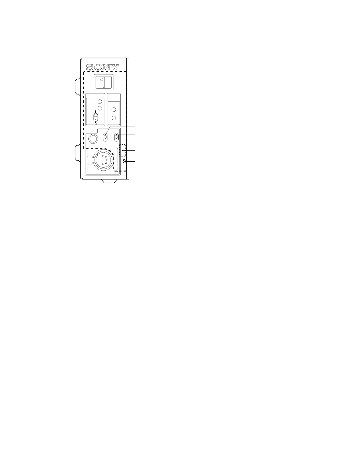
CAMERA connector (optical/electrical composite connector)
VIDEO Y/PB/P
R
Conforms to BTA-S004B, 1.485 Gbps/
1.4835 Gbps serial
SMPTE 292M
RET VIDEO Y/P
B/PR
Conforms to BTA-S004B, 1.485 Gbps/
1.4835 Gbps serial
SMPTE 292M
INCOM 2ch
MIC 2ch
DIGITAL AUDIO (AES/EBU)
CAMERA COMMAND
PROMPTER
Analog signal
FRAME REFERENCE IN : BNC
± 0.3 V, ternary SYNC, 75 Z
Or, black burst signal 0.286 V p-p, 75 Z
FRAME REFERENCE OUT : BNC
THROUGH OUT/0.3 V p-p, FRAME SYNC pulse, 75 Z
HDCU-950 IMM
1-3 (E)
1-4. Matching Connectors and Cables
MIC1/MCI2 (XLR 3-pin, Male)
12
3
__
_ EXT VIEW
__
__
_
__
(0 dBu = 0.775 Vrms)
No. Signal Specifications
1 MIC OUT (G) 0 dBu/_20 dBu
2 MIC OUT (X) (Selectable with S502,
3 MIC OUT (Y) S503/AVP-4)
MIC REMOTE (D-sub 15-pin, Female)
(WF REMOTE (D-sub 15-pin, Female))
18
15 9
__
_ EXT VIEW
__
__
_
__
In the case of MIC REMOTE mode : S423-3/AT-149 →
OFF
*1 : CHU MIC 1/2 AMP GAIN
CONT0 CONT1 CONT2 CHU MIC AMP GAIN
H H H 60 dB
L H H 50 dB
H L (H) H (L) 40 dB
L L (H) H (L) 30 dB
H H (L) L (H) 20 dB
The setup for HDCU-700A mode is shown in parenthesis ( ).
In the case of HDCU-700A mode : S423-2/AT-149 → ON
*2 :
8pin 15pin MIC GAIN CONT
L L MIC 1 and 2 ON
L H MIC 1 ON
H L MIC 2 ON
H H INTERNAL set
*3 :
CONT1 CONT2 ASPECT
L H SQ (16 : 9)
H H EC (4 : 3)
L L INTERNAL set
H L LB (4 : 3)
No. Signal Specifications
1 +5.5 V OUT Max. 250 mA
2 TALLY GND GND for TALLY
3 G TALLY OUT ON (GND) : Max. 30 mA IN
4 R TALLY OUT ON (GND) : Max. 30 mA IN
5 CHU MIC CONT2 *1 Refer to the right column.
AMP
6
GAIN IN
7
8 MIC1 GAIN CONT *2 Refer to the right column.
ON/OFF IN
9 GND GND for +5.5 V
10 TALLY OUT R/G TALLY OUT
11 NC No connection
12 ASPECT REMOTE L : REMOTE
ON/OFF
13 ASPECT CONT1 *3 Refer to the right column.
14 CTL CONT2
15 MIC2 GAIN CONT *2 Refer to the right column.
ON/OFF IN
CONT1
CONT0
ON (GND) : Max. 30 mA IN
In the case of WF REMOTE mode : S423-3/AT-149→ ON
Recall system
No. Signal Specifications
1 NC No connection
2 NC No connection
3 NC No connection
4 NC No connection
5 RECALL2 (G) LOW ACTIVE
6 RECALL3 (B)
7 RECALL1 (R)
8 RECALL4 (SEQ)
9 GND
10 NC No connection
11 NC No connection
12 RECALL5 (ENC) LOW ACTIVE
13 RECALL6 (R+B)
14 RECALL7 (R+G)
15 RECALL8 (G+B)
1-4 (E)
HDCU-950 IMM
1-4. Matching Connectors and Cables
INCOM/TALLY/PGM (D-sub 25-pin, Female)
113
25 14
__
_ EXT VIEW
__
__
_
__
(0 dBu = 0.775 Vrms)
No. Signal Specifications
1 ENG (R) (X) OUT ENG SYSTEM RECEIVE
2 ENG (R) (Y) OUT 0 dBu BALANCED
3 ENG (G) GND for ENG
4 ENG (T) (X) IN ENG SYSTEM TALK
5 ENG (T) (Y) IN 0 dBu BALANCED
6 PGM1 (X) IN _20 dBu/0 dBu
7 PGM1 (Y) IN (Selectable with
8 PGM1 (G) IN S500/AVP-4)
9 GND GND for AUX
10 AUX3
11 R TALLY (X) IN ON : 24 Vdc, TTL (H), SHORT
12 R TALLY (Y) IN OFF : 0 Vdc, TTL (L), OPEN
13 GND CHASSIS GND
14 PROD (R) (X) OUT PROD SYSTEM
15 PROD (R) (Y) OUT RECEIVE 0 dBu BALANCED
16 PROD (G) GND for PROD
17 PROD (T) (X) IN PROD SYSTEM TALK
18 PROD (T) (Y) IN 0 dBu BALANCED
19 PGM2 (X) IN _20 dBu/0 dBu
20 PGM2 (Y) IN (Selectable with
21 PGM2 (G) IN S501/AVP-4)
22 AUX4
23 AUX5
24 G TALLY (X) IN ON : 24 Vdc, TTL (H), SHORT
25 G TALLY (Y) IN OFF : 0 Vdc, TTL (L), OPEN
WF MODE (4-pin, Female)
4
1
3
2
__
_ EXT VIEW
__
__
_
__
No. Signal Specifications
1 SEQ CONT OUT (G) OPEN COLLECTOR
+(PNP)/_(NPN)
2 SEQ CONT OUT (X) (Selectable with S301/RC-91)
3 STAIR CASE OUT (X) *4
4 STAIR CASE OUT (G) GND for STAIR CASE
*4 : Stair Case signal
+1
12 V
_6
RG B
DC 0 ±2 V
RCP/CNU (8-pin, Female)
1
2
7
8
6
3
5
4
__
_ EXT VIEW
__
No. Signal Specifications
1 TX (+) CCU SERIAL DATA
2 TX (_)
3 RX (+) RCP/CNU/BVP/MSU/
4 RX (_) VCS SERIAL DATA
5 TX GND GND for TX
6 POWER (+) OUT RCP POWER, +30 V
7 POWER (_) OUT GND for POWER
8 SPARE
__
_
__
HDCU-950 IMM
1-5 (E)
1-4. Matching Connectors and Cables
INCOM (5-pin, Female)
5
__
_ EXT VIEW
__
1
2
4
3
__
_
__
(0 dBu = 0.775 Vrms)
No. Signal Specifications
1 INCOM (T) IN (Y) _20 dB
2 INCOM (T) IN (X) (CARBON MIC)
_40 dB
(ECM MIC)
_60 dB
(DYNAMIC MIC)
3 INCOM (T) IN (G) GND for INCOM
4 INCOM (R) OUT (X) Max. 12 dBu
5 NC No connection
1-4-2. Connection Connectors
When connecting cables to each connector of the connector panel during installation or service, connect the following connectors or equivalent to the tip.
Connector Connector/cable
HDCU-950
CAMERA LEMO®
PUW. 3K. 93C. TLCC96 *1
(HDC-900/950/930 side)
CCU LEMO®
FUW. 3K. 93C. TLMC96 *1
HDCU-950 1-569-370-12 PLUG, BNC
REFERENCE IN
PIX OUT
WF OUT
SYNC OUT
PROMPTER IN
HKCU-951
Y/G OUT
B-Y/B OUT
R-Y/R OUT
VBS OUT
Connector Connector/cable
HDCU-950 1-569-370-12 PLUG, BNC or
RET IN (1-3) BELDEN8281 Cable or
SERIAL OUTPUT (1-2, MONI)
SD SDI OUT (1-3)
HKCU-953
HD SDI OUT (1-2)
MIC1/MIC2 1-508-083-00 XLR 3-pin female
(3-pin, Male) or CANNON XLR-3-11C
MIC REMOTE 1-506-582-11 D-sub 15-pin, male
(WF REMTOE) or JAE DA-CI-J10 equivalent
(D-sub 15-pin, Female)
INCOM/TALLY/PGM D-sub 25-pin, male
(D-sub 25-pin, Female) JAE DA-25PF-N equivalent
WF MODE 1-560-155-00 PLUG, 4-pin male
(4-pin, Female) (supplied)
RCP/CNU 1-766-848-11 PLUG, 8-pin male
(8-pin, Female)
INCOM 1-508-370-11 XLR 5-pin, male
(5-pin, Female) or CANNON XLR-5-12C
*1 : Caution in making the optical/electric signal composite cable:
When making the optical/electric signal composite cable used for this
camera system, the connection connectors specified in this manual
must be used in order to comply with the limits for EMC regulations.
equivalent
equivalent
or CCA cable assembly (optional)
CCA-5-30 (30 m), CCA-5-10
(10 m), CCA-5-3 (3 m)
equivalent
1-4-3. Note when Connecting CAMERA
Connector
Before connecting the unit to the camera adapter, clean the
following optical contact blocks.
For the cleaning procedure, refer to Section 3-1, “Cleaning
of Connector/Cable”.
. CAMERA connector of the unit
. CCU connector of the camera adaptor side
. Optical/electric signal composite cable
HKCU-953
FRAME REFERENCE IN
FRAME REFERENCE OUT
1-6 (E)
HDCU-950 IMM
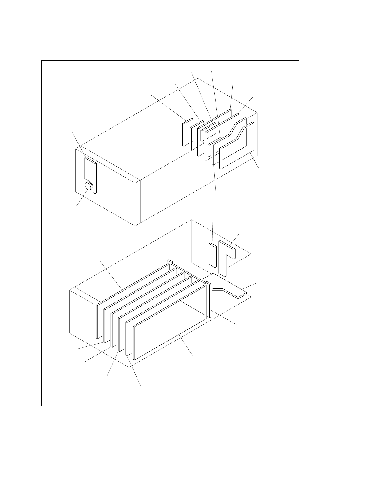
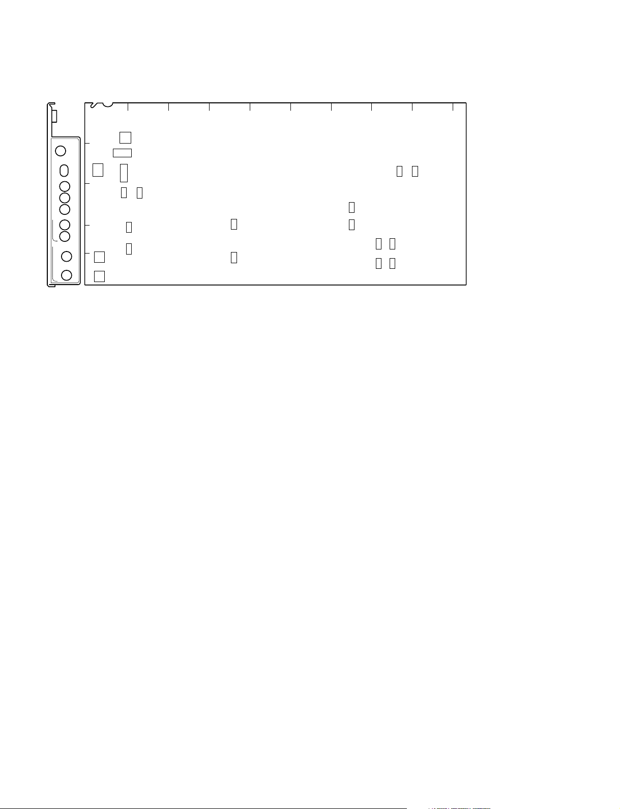
1-5. Circuit Boards Layouts
CN-2220 board
1-5. Circuit Boards Layouts
RX-67boardTX-83 board
SDI-70 board
AU-281 board
CN-2227 board
AT-149 board
CN-2219 board
HIF-5 board
VDA-61 board
(HKCU-951) or
DIF-124 board
DIF-124 board or
SDI-73 board (HKCU-953)
CN-2226 board
CN-2224 board
CN-2225 board
MB-951 board
AVP-4 board
DTX-1 board
DRX-1 board
RC-91 board or
FC-88 board (HKCU-953)
EN-145 board (HKCU-951) or
RC-91 board
n
To install the optional board is required depending on the system to be used. For details, refer to Sections
1-8. “Installing the HKCU-951/953” and 2. “System Setup”.
HDCU-950 IMM
1-7 (E)
1-6. Setting of Switches on Boards
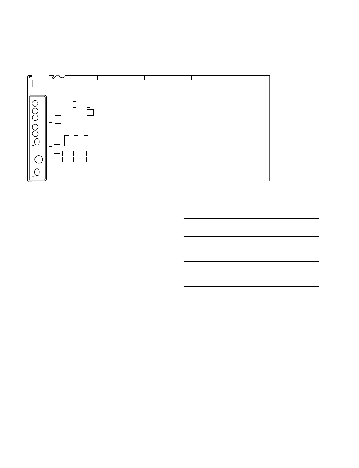
1-6. Setting of Switches on Boards
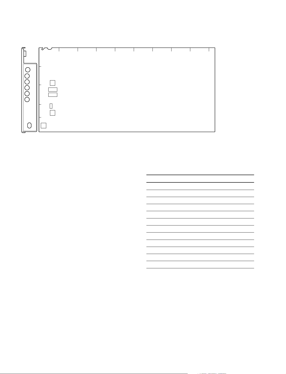
1-6-1. AT-149 Board
AB C D E F G H JK
1
AT
POWER
/1.001
90H
REFERENCE
REF IN
UN
LOCK
HD
REM
BB
H PHASE
STEP
COARSE
ADV
DELAY
2
3
S427
S405
4
S428
5
S404
S403
S406
S407
S423
S422
S419
S409
S410
S416
S417
S424
S421
S418
S408
S402
S412
S420
S411
S414
S413
S202
AT-149 board (A side/panel side)
n
Do not change the settings of the switches described
“Factory use only” and unused switches.
. S202
Factory use only
Factory setting : OFF
. S402 (SKIN GATE LEV)
When S408 on the AT-149 board is set to LOC, adjusts
the zebra level of the skin gate of the MONITOR output
signal.
Factory setting : 8
. S403 (MOD LEVEL)
When S408 on the AT-149 board is set to LOC, this
switch is valid.
When S410 on the AT-149 board is set to ON, adjusts
the aspect modulation level of the MONITOR output
signal.
. 404 (MARKER SEL)
Sets the type of the aspect marker.
Setting switches Aspect marker
0 4 : 3
1 13 : 9
2 14 : 9
3 15 : 9
4 14.94 : 9
5 16 : 8.649
6 16 : 6.75
7 Not used
8 through F Interlocking aspect ratio of the
down-converter
Factory setting : 8
. 405 (H PHASE STEP)
Performs the coarse adjustment of the H phase when
S427 on the AT-149 board is set to position other than
REM. Perform the fine adjustment using S428 on the
AT-149 board.
Factory setting : 8
1-8 (E)
. S406 (V PHASE)
Adjusts the vertical phase with regard to the reference
signal in unit of line.
Factory setting : 8
. S407 (CONVERSION DELAY PHASE)
Performs the fine adjustment of the delay amount of the
signal between HD and SD that is set by S417 on the
AT-149, in unit of 1H or 2.2 usec.
Factory setting : 0
HDCU-950 IMM

1-6. Setting of Switches on Boards
. S408 (MARKER REMOTE/LOCAL SEL)
Selects either the HDCU-950 or the RCP/MSU connected outside in order to control the aspect marker and skin
gate signal to be inserted in the HD SDI MONITOR
output signal and in the PIX output signal that are output
from the MONI connector on the rear panel.
REM : Control is performed by RCP/MSU etc., con-
nected outside.
LOC : Control is performed by the switches (S402,
S403, S409 and S410) on the AT-149 board.
Factory setting : REM
. S409 (MARKER)
When S408 on the AT-149 board is set to LOC, this
switch enables selection whether the ASPECT MARKER signal is inserted or not in the HD SDI MONITOR
output signal and in the PIX output signal that are output
from the MONI connector on the rear panel.
ON : Inserted
OFF : Not inserted
Factory setting : OFF
. S410 (MODULAT)
When S408 on the AT-149 board is set to LOC, this
switch enables selection whether the HD SDI MONITOR output signal that is output from the MONI connector on the rear panel, receives the aspect modulation
processing or not.
ON : Processing is ON
OFF : Processing is OFF
Factory setting : OFF
. S411 (RCP-PORT)
Not used.
Factory setting : ( indicates the switch lever
position)
S411
. S414 (FIBER/COAX-1/COAX-2 SEL)
When S423-8 on the AT-149 board is set to ON, select
the camera signal reception mode of the HDCU-950.
When S423-8 on the AT-149 board is set to OFF
(factory setting), the signal is connected by the normal
optical/electrical composite cable.
FIBER : Connection by normal optical/electrical
composite cable
COAX-1 :One-way connection using a BNC cable
COAX-2 :Bi-directional connection using two BNC
*2
cables
Factory setting : FIBER
*1: After receiving the HD-SDI signal output from the camera, the signal
is locked and each signal is output correctly. (RET3 connector is
used for the HD-SDI signal input connector from the camera.)
*2: Connecting the camera equipped with the HD-SDI input/output is
possible using the two BNC cables instead of the optical/electrical
composite cable. Then the normal operation is possible except the
power feeding function. (As to the HD-SDI output signal to the
camera, the output signal from HD SDI MONITOR is used.)
However, this function cannot be used by default at present. If you
want to use this function, consult your local Sony Sales Office/
Service Center.
. S416 (REF-10F-BB) (NTSC only)
Sets this switch when the multi frame is going to be
locked using the 10F-BB signal (SMPTE318M) as a
reference signal.
ON : Sets the 10F-BB signal as reference.
OFF : When the 10F-BB signal is not input to REFER-
ENCE.
Factory setting : OFF
. S417 (CONVERSION DELAY)
Selects delay amount between the HD-SDI output signal
and the SDI signal after the HD-SDI signal is downconverted.
90H : Minimum delay mode equivalent to 90H
lines of HD signal.
1FRAM : Unity phase mode with 1 frame delay
Factory setting : 90H
*1
. S412 (SYNC OUT HD/SD)
Selects the type of the SYNC signal to be output from
the SYNC OUT connector on the rear panel.
HD : HD SYNC signal output
SD : SD SYNC signal output
Factory setting : SD
. S413
Not used.
Factory setting : ( indicates the switch lever
position)
S413
HDCU-950 IMM
. S418 (FIELD FREQUENCY SEL)
. S419 (INTR/PROG/540P SEL)
When S420 on the AT-149 board is set to the position
other than REMOTE, sets the conversion format of the
MAIN HD SDI output signal that is output from the HD
SDI OUT1 and 2 connectors on the rear panel.
n
The MULTIFORMAT setting of the camera side shall
have the same setting too.
1-9 (E)
1-6. Setting of Switches on Boards
Factory setting : 60V (S418)
INTR (S419)
FORMAT S420 S418 S419
1080/60 (or 59.94) i 1.000 60V INTR
(or 1.001)
1080/30 (or 29.97) PsF 1.000 60V PROG
1080/50i 1.000 50V INTR
1080/25PsF 1.000 50V PROG
1080/24 (or 23.98) PsF 1.000 48V PROG
540/60 (or 59.94) PsF 1.000 60V 540P
(or 1.001)
(or 1.001)
(or 1.001)
n
540P and the formats other that what are describe above,
are not supported at present.
. S420 (FRAME FREQ.SELECT)
Select coefficient between x1and x
1.000 1.001
1
depending upon the HD signal frame frequency.
/1.001 :
1.001
1
times
/1.000 : 1 time
REMOTE : Control is performed by RCP/MSU, etc.,
connected outside.
Factory setting : REMOTE
. S421 (1-8 CCU No.)
This switch is mainly used to set the CCU numbers when
RCP is connected to the HDCU-950.
Use switches 1 to 8 to set the CCU numbers from 1 to 96
in BCD notation.
Use switches 1 to 4 to set the first digit and use switches
5 to 8 to set the second digit. (“a” to “f” are invalid.)
OFF ON
First
digit
Second
digit
CCU No.
1
2
01
3
4
5
6
567
7
8
50 61 72 83 94
2
34
8
Factory setting : All OFF
. S422-1 to 5 (CCU MODE SET 2)
Sets the CCU mode.
Set all to OFF during ordinary operation.
Factory setting : All OFF
-6 : (RCP Sim-Cont)
-7 : (P-B CHARA MIX)
-8 : (TRUNK)
1-10 (E)
. S423 (CCU MODE SET 1)
Sets the CCU mode.
Factory setting : All OFF
-1 : Sets the SD signal format when S420 on the AT-149
board is set to position other than REMOTE.
ON : PAL (625/50)
OFF : NTSC (525/60)
-2 : The remote control code of MIC GAIN can be
switched to that of the HDCU-700A.
ON : HDCU-700A mode
OFF : Standard (default)
-3 : Selects the function of the MIC REMOTE connector
on the rear panel.
ON : WFM REMOTE CTL
OFF : MIC REMOTE CTL
-4 : Set the switch to OFF. (900)
-5 : Set the switch to OFF. (RCP-POW)
-6 :
The PIX select control from the RCP can be disabled.
ON : Enabled
OFF : Disabled
-7 : Set the switching control of PIX/WFM.
ON : Controllable only from RCP
OFF : Controllable from both MSU and RCP
-8 : Sets the reception mode of the camera HD-SDI
signal using the electrical coaxial cable. Set this
switch to OFF during ordinary operation.
ON : Depending on the setting of S414 on the AF-
149 board.
OFF : Connection by normal optical/electrical
composite cable
. S424-1 to 8
Factory use only
Factory setting : All OFF
. S427 (REFERENCE SIGNAL SEL)
Selects the type and phase control methods of the
external sync signal.
HD : Sync-locks to the HD reference signal.
(Supports automatically the frame frequency of
9
the reference signal to be input.)
BB : Sync-locks to the SD reference signal (BB).
(When the HKCU-951 is mounted, VBS OUT is
SC-locked.)
REM : Control is performed by RCP/MSU, etc.,
connected outside.
Factory setting : REM
. S428 (H PHASE COARSE)
Performs the fine adjustment of the H phase when S427 on
the AT-149 board is set to position other than REM. Perform
the coarse adjustment using S405 on the AT-149 board.
Factory setting : CENTER
HDCU-950 IMM
1-6. Setting of Switches on Boards
1-6-2. AU-281 Board (Front Panel)
OFF
CABLE
ALRAM
OPEN
SHORT
PROD
PRIV
PGM
ENG
AU-281 board (Front panel)
S3
S2
S4
S5
POWER
CAM
MAIN
S1
INCOM MIC-ON
. S1 (POWER)
Turns ON/OFF the main power of this unit.
ON : Power ON
OFF : Power OFF
Factory setting : OFF
. S4 (TALK GAIN)
Sets the microphone input level according to the type of
headset microphone to be connected to the INCOM
connector on the front panel.
DYNAMIC : When using a dynamic microphone
(_60 dB)
ECM : When using a electric condenser micro-
phone (_40 dB)
CARBON : When using a carbon microphone
(_20 dB)
Factory setting : CARBON
.
S5 (TALK DYNAMIC/ECM MIC UNBALANCE GND)
When the headset microphone to be connected to the
INCOM connector on the front panel is DYNAMIC or
ECM, this switch sets the input level according to the
type (balanced/unbalanced) of the headset microphone.
GND : In case of unbalanced type (upper side)
OPEN : In case of balanced type (lower side)
Factory setting : OPEN
. S2 (INCOM SELECT)
Selects the line to which the INCOM connector on the
front panel is connected.
PROD : Producer line
PRIV: Private (When the unit is disconnected from
the producer line or engineer line, only the
intercom between the unit and the camera is
possible.)
ENG : Engineer line
Factory setting : PRIV
. S3 (INCOM MIC)
Performs the switching operations between ON/OFF of
the headset microphone connected to the INCOM
connector on the front panel and receiving audio/PGM
(program audio) of the producer line (or engineer line).
MIC-ON : Turns ON the headset microphone.
MIC-OFF : Turns OFF the headset microphone.
PGM : The program audio is output to the INCOM
connector on the front panel.
Factory setting : MIC-OFF
n
Selecting the receiving audio is valid when S11 on the
AVP-4 board is OFF.
HDCU-950 IMM
1-11 (E)
1-6. Setting of Switches on Boards
1-6-3. AVP-4 Board
AB C D E F G H JK
1
S11
S12
S15
S16
S14
S710
S610
AVP
POWER
INTERCOM
PGM1
MIX
PGM2
2WIRE CANCEL
MIC LEVEL
NORM
MIC1
NORM
MIC2
PGM1
LEVEL
PGM2
LEVEL
SIDE
TONE
PROD
ENG
S1
2
3
4
S2
MIN
5
S3
MIN
S711
S611
S503
S502
S103
S500S501
S101
S100S102
AVP-4 board (A side/panel side)
n
Do not change the settings of the switches described
“Factory use only”.
. S1 (FP PGM SEL PGM1/MIX/PGM2)
Selects the PGM (program audio) that is output to the
INCOM connector on the front panel.
PGM 1 : PGM CH-1
MIX : PGM CH-1 + PGM CH-2
PGM 2 : PGM CH-2
Factory setting : PGM 1
. S2 (MIC 1 LEVEL)
. S3 (MIC 2 LEVEL)
Use these switches to select AMP GAIN of MIC CH-1/
CH-2 of the camera head using this unit. Set GAIN to
either 60 dB (NORMAL), 50 dB, 40 dB, 30 dB or 20 dB
(MIN) according to MIC sensitivity and audio conditions
during shooting.
Factory setting : [NORM] (60 dB)
. S11 (FP INCOM MODE SEP/MIX/OFF)
Selects the receiving audio of the producer line (or
engineer line) and also selects the mix mode of the PGM
(program audio).
SEP : The receiving audio and the PGM (program
audio) are output in the right and left channels
separately.
MIX : The receiving audio and the PGM (program
audio) are mixed and output.
OFF : Not mixed. (Depends on the setting of S3 on the
AU-281 board.)
n
There is not the mix mode of the producer line and the
engineer line.
Factory setting : OFF
. S12 (INPUT INCOM SELECT)
Set this switch to either channel 1 (PROD) or channel 2
(PROD, ENG) according to the intercom system. When
channel 1 is set, PROD is selected regardless of the
setting of the ENG/PROD select switches of the camera
side and the CCU side.
Factory setting : Channel 2
1-12 (E)
. S14 (PGM INPUT SEL ANA/SDI)
Selects the type of the PGM (program audio).
ANA : Analog system PGM (Input signals to the
INCOM/TALLY/PGM connectors)
SDI : Embedded digital audio of the SDI signal
selected by S605 on the DTX-1 board.
Factory setting : ANA
HDCU-950 IMM

1-6. Setting of Switches on Boards
. S15 (MIC DELAY)
This switch is used to match the amount of delay of MIC
and AES/EBU format audio signal with the video signal.
About 5 msec. is delayed per one step.
Example) : 7 : 1 FRAME DELAY (30 FRAME/SEC)
8 : 1 FRAME DELAY (25 FRAME/SEC)
Factory setting : 0
. S16-1 to 8
Factory use only
Factory setting : All OFF
. S100 (R TALLY POWER/CONTACT)
. S102 (R TALLY POWER/TTL)
Set these switches according to the signal standard of the
R TALLY signal to be input in the INCOM/TALLY/
PGM connector on the rear panel. Refer to the following
table for the relation between signals and switch setups.
Factory setting : CONTACT (S100)
TTL (S102)
. S101 (G TALLY POWER/CONTACT)
. S103 (G TALLY POWER/TTL)
Set these switches according to the signal standard of the
G TALLY signal to be input in the INCOM/TALLY/
PGM connector on the rear panel. Refer to the following
table for the relation between signals and switch setups.
Factory setting : CONTACT (S101)
TTL (S103)
Setting the tally system
. S501 (PGM 2 SEL)
Set the input signal level of the PGM (program audio)
CH-2 to either 0 dBu or _20 dBu.
Factory setting : 0 dBu
. 502 (MIC 2 OUT LEVEL)
Set the AUDIO signal level of the MIC-2 connector on
the rear panel to either 0 dBu or _20 dBu.
Factory setting : 0 dBu
. S503 (MIC 1 OUT LEVEL)
Set the AUDIO signal level of the MIC-1 connector on
the rear panel to either 0 dBu or _20 dBu.
Factory setting : 0 dBu
. S610 (PROD RTS/CLEAR)
. S611 (PROD INCOM ENG SELECT)
Selects the intercom system of the producer line.
Factory setting : 4W (S611)
RTS (S610)
S611 S610
4-wire system 4W _
RTS system RTS RTS
Clear-Com system RTS CC
. S710 (ENG RTS/CLEAR)
. S711 (ENG INCOM ENG SELECT)
Selects the intercom system of the engineer line.
Factory setting : 4W (S711)
RTS (S710)
Red tally Green tally
Switch S100 S102 S101 S103
Signal POWER/ POWER/ POWER/ POWER/
standard CONTACT TTL CONTACT TTL
Contact CONTACT _ CONTACT _
supply
24 V voltage POWER POWER POWER POWER
supply
5 V voltage POWER TTL POWER TTL
supply
. S500 (PGM 1 SEL)
Set the input signal level of the PGM (program audio)
CH-1 to either 0 dBu or _20 dBu.
Factory setting : 0 dBu
HDCU-950 IMM
S711 S710
4-wire system 4W _
RTS system RTS RTS
Clear-Com system RTS CC
1-13 (E)
1-6. Setting of Switches on Boards
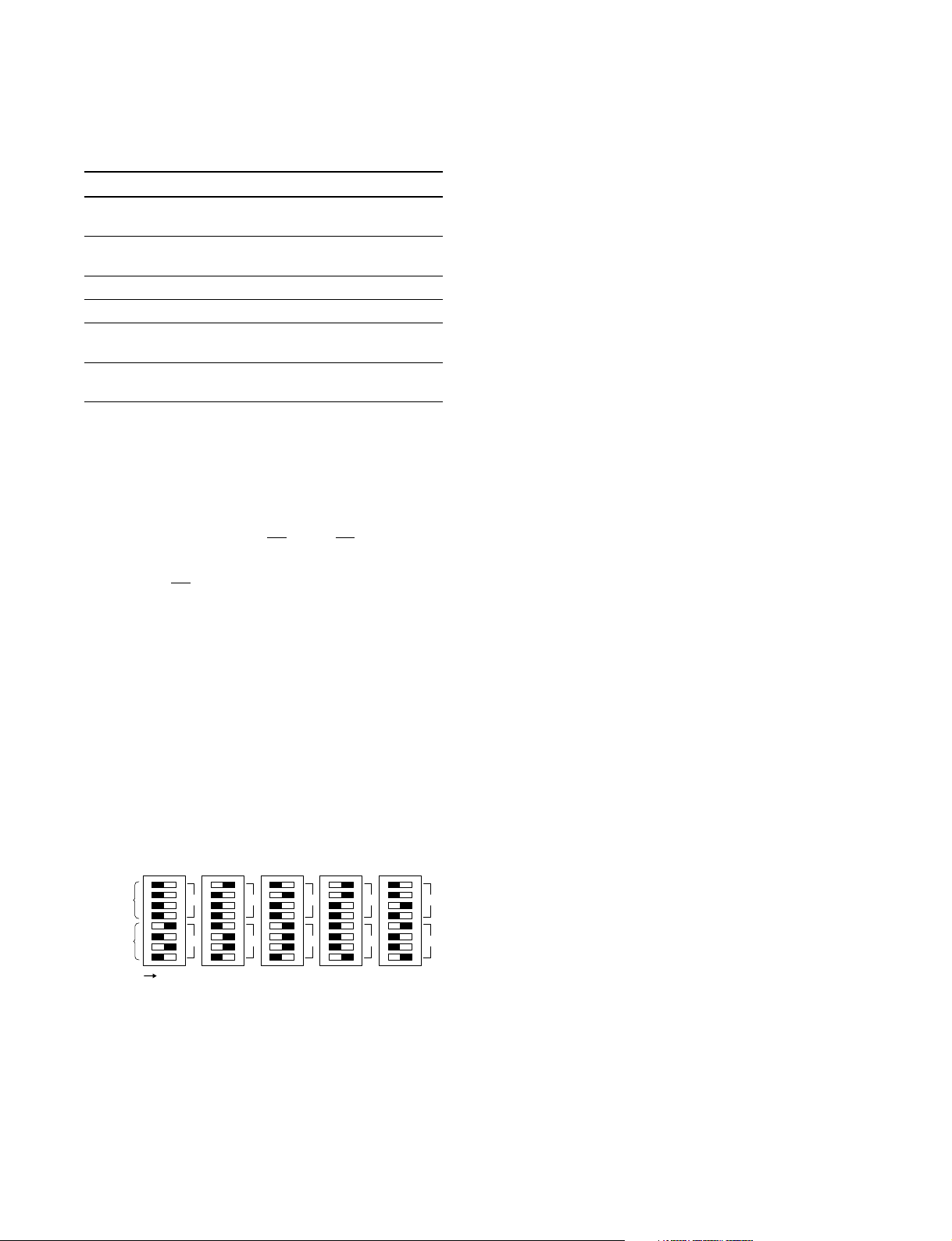
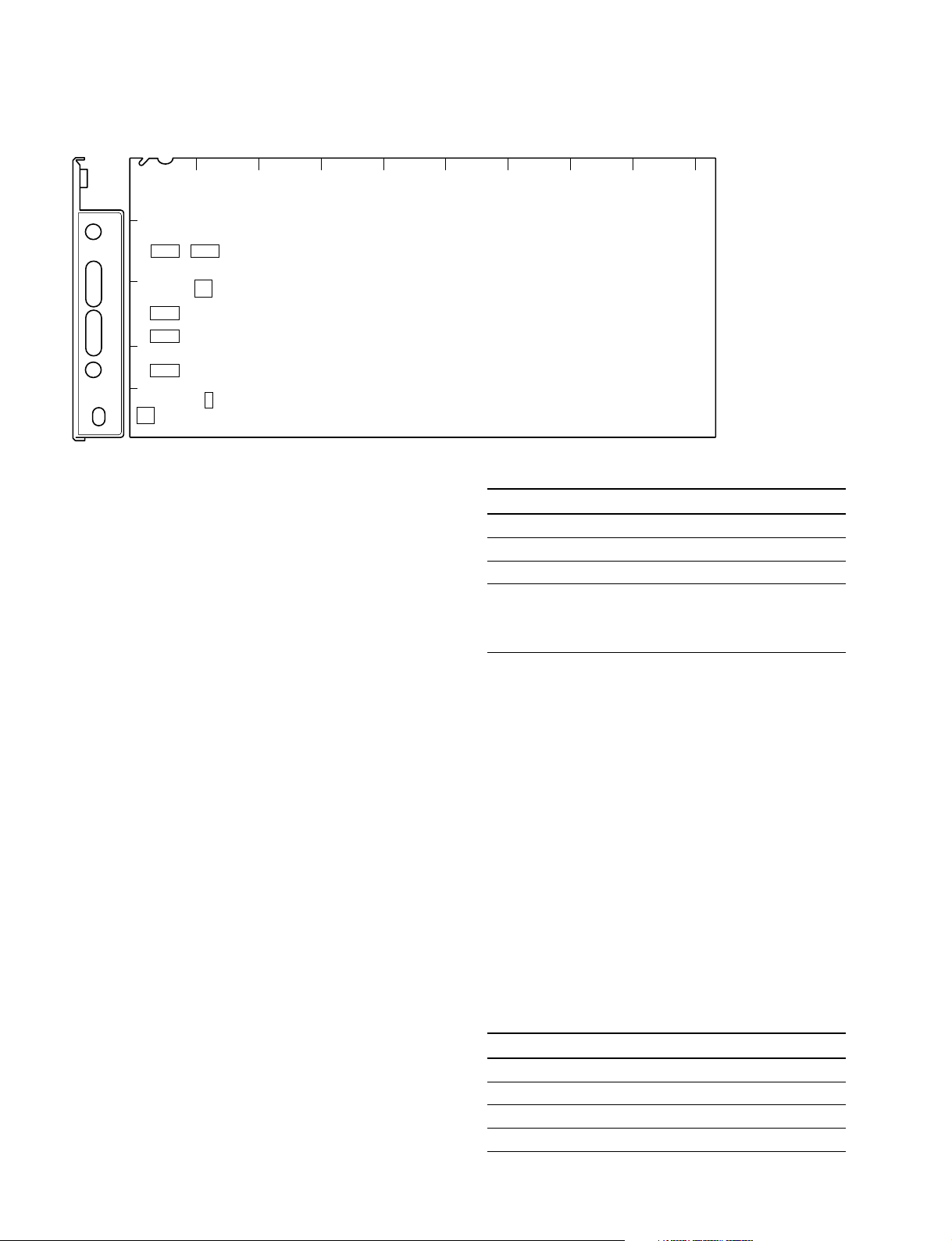
1-6-4. DRX-1 Board
AB C D E F G H JK
1
DRX
POWER
60
2
50
48
PsF
540P
CHARACTER
REW
FF
3
4
5
S204
S206
S202
S201
S205
S203
DRX-1 board (A side/panel side)
n
Do not change the settings of the switches described
“Factory use only”.
. S201 (GRAY ON/OFF)
When you turn off the power of the camera or when the
communication with the camera is cut, this switch
selects the signal to be output from the CCU.
ON : Gray signal
OFF : Color bar signal
Factory setting : OFF
. S202-1 to 8
Factory use only
Factory setting : All OFF
. S203 (CHARACTER)
The character page to be mixed into the signal that is
output from the MONI connector on the rear panel, can
be changed with REW/FF.
REW :Returns to previous page.
FF : Goes to next page.
Factory setting : CENTER
. S205 (CB SEL)
Selects the color bar signal that is output from the HD
SDI OUT 1 and 2 connectors (of the HDCU-950/HKCU-
953) on the rear panel.
Setting switches Color bar
0 16 : 9-100%-CB (non-sprit) BAR
1 16 : 9-75%-CB (non-sprit)
2 4 : 3-100CB (non-sprit)
3 4 : 3-75%-CB (non-sprit)
4 16 : 9 SMPTE-CB (_I, +Q)
5 16 : 9 SMPTE-CB (0%)
6 4 : 3 SMPTE-CB (_I, +Q)
7 4 : 3 SMPTE-CB (0%)
8 Multi Format-A ARIB-75%-SMPTE-CB
9 Multi Format-B ARIB-100%-SMPTE-CB
A Multi Format-C ARIB-CB (+I)
B Multi Format-C SMPTE-CB (_I, +Q)
Factory setting : 0
. S204
Factory use only
Factory setting : 0
1-14 (E)
HDCU-950 IMM

. S206
Factory setting : All OFF
-1, 2
Factory use only
-3 (MAIN/MONI CHANGE)
When this switch is set to ON, the character signal and
the marker signal are mixed with the all output signals
except the HD-SDI-MONITOR output.
ON : Change mode
OFF : Normal mode
-4 (MONI CHARACTER OFF)
Selects whether the character signal and the marker
signal are mixed or not to the signal to be output from
the MONI connector on the rear panel.
ON : Forced-OFF (Not mixed)
OFF : Normal mode (Mixed)
-5 (GRAY SIGNAL BAR-CHAR ON/OFF)
This switch enables mixing of the color bar character
with the gray signal that is output when camera is turned
off.
ON : GRAY BAR-CHAR ON
OFF : GRAY BAR-CHAR OFF
1-6. Setting of Switches on Boards
HDCU-950 IMM
1-15 (E)
1-6. Setting of Switches on Boards
1-6-5. DTX-1 Board
AB C D E F G H JK
1
DTX
POWER
OPTICAL
CONDITION
CCU
CHU
CHU
LOCK
S607 S608
2
3
4
S610
S606
S603
S604
RETURN SET
5
HD
REM
SD
S605
S601
n
Do not change the settings of the switches described
“Factory use only”.
. S601 (SD RETURN FORMAT)
Selects the signal format that is input to the RET1 to 3
connectors on the rear panel when S605 on the DTX-1
board is set to SD.
VBS (20) : Analog VBS
SDI (80) : SD SDI (D1)
Factory setting : SDI
. S603 (SD RET ASPECT)
This switch is valid when S605 on the DTX-1 board is
set to SD.
Selects the aspect ratio of the SD return signal to be
input to the RET1 to 3 and RET4 (PROMPTER) connectors on the rear panel when S601 on the DTX-1 board is
set to SD.
S603-1, -2 : RET1
S603-3, -4 : RET2
S603-5, -6 : RET3
S603-7, -8 : RET4 (PROMPTER)
DTX-1 board (A side/panel side)
S603-1, -3, -5, -7 S603-2, -4, -6, -8 Aspect ratio
ON ON Letter box
ON OFF Edge-crop
OFF ON Squeeze
*1
*1
*1
OFF OFF It is interlocked with
the down-conversion
aspect ratio of the
RC-91 board output.
*1 : Letter box : The HD video signal of 16 : 9 (or aspect ratio set with
Edge-crop : Video signal as large as 4 : 3 is cut from the HD video
Squeeze : The HD video signal of 16 : 9 is converted to the SD
S604 on the DTX-1 board) is inserted in the picture
frame of 4 : 3 as it is and converted to the SD signal.
(The black level is inserted in the top and bottom of the
picture.)
signal and is converted to the SD signal.
signal as it is.
Factory setting : All OFF
. S604 (LB ASPECT)
This switch is valid when S605 on the DTX-1 board is
set to SD.
Select the aspect ratio of the letter box, when S603 on
the DTX-1 board is set to letter box.
S604-1, -2 : RET1
S604-3, -4 : RET2
S604-5, -6 : RET3
S604-7, -8 : RET4 (PROMPTER)
1-16 (E)
S604-1, -3, -5, -7 S604-2, -4, -6, -8 Aspect ratio
ON ON 13 : 9
ON OFF 14 : 9
OFF ON 15 : 9
OFF OFF 16 : 9
Factory setting : All OFF
HDCU-950 IMM

1-6. Setting of Switches on Boards
. S605 (RETURN SET)
Sets the format of the return signal to be input to the
RET1 to 3 connectors on the rear panel.
HD : Sets the RET1 to 3 to the HD-SDI.
SD : Sets the RET1 to 3 to SD. (Depends on the
setting of S601, S603 and S604 on the DTX-1
board.)
REM : Sets the format of each return signal from RM/
MSU, etc. connected outside.
Factory setting : REM
. S606 (RET FC SET)
Sets the frame conversion type of the return signal to be
input to the RET1 to 3 and RET4 (PROMPTER) connectors on the rear panel.
S606-1, -2 : RET1
S606-3, -4 : RET2
S606-5, -6 : RET3
S606-7, -8 : RET4 (PROMPTER)
S606-1, -3, S606-2, -4, Type of frame conversion
-5, -7 -6, -8
ON ON THROUGH :
Frame conversion is not
performed.
OFF ON A (24PsF conversion) :
When the camera side is
24PsF, the forced-reverse
conversion is performed.
(Conversion to reconstruct
24PsF)
ON OFF B (48i conversion) :
When the camera side is
24PsF, the forced-reverse
conversion is performed.
(Conversion to 48i format
by simple skipping)
OFF OFF AUTO :
Depends on the setting of
S1-1 on the FC-88 board.
. S607 (RETURN MODE)
Perform setting of the return signal.
Factory setting : All OFF
-1 (RET-DLY)
Sets the SD return signal and the delay amount of the
phase during up-convert.
ON : Up-convert in the least time
OFF : 1-field delays at maximum.
-2 (RET4-VBS)
Sets whether the PROMPTER connecter on the rear
panel is used or not as RET4 (VBS input).
ON : Uses it as PROMPTER input.
OFF : Uses it as RETURN4 (VBS input).
-3 to 8
Factory use only
. S608-1 to 8
Factory use only
Factory setting : All OFF
. S610 (FC SEQUENCE)
Phase at the conversion cycle can be changed during the
frame frequency conversion of the return signal. (Timing
to delete the field can be freely selected during conversion of 60i → 48i and 50i → 48i.)
Factory setting : 0
Factory setting : All OFF
HDCU-950 IMM
1-17 (E)
 Loading...