

Page 1

HD MULTI PURPOSE CAMERA
HDC-P1
OPERATION MANUAL [English]
1st Edition (Revised 1)
Page 2

Before operating the unit, please read this manual thoroughly
and retain it for future reference.
WARNING
To reduce the risk of fire or electric shock,
do not expose this apparatus to rain or
moisture.
To avoid electrical shock, do not open the
cabinet. Refer servicing to qualified
personnel only.
For the customers in the U.S.A.
This equipment has been tested and found to comply with the
limits for a Class A digital device, pursuant to part 15 of the
FCC Rules. These limits are designed to provide reasonable
protection against harmful interference when the equipment is
operated in a commercial environment. This equipment
generates, uses, and can radiate radio frequency energy and,
if not installed and used in accordance with the instruction
manual, may cause harmful interference to radio
communications. Operation of this equipment in a residential
area is likely to cause harmful interference in which case the
user will be required to correct the interference at his own
expense.
AVERTISSEMENT
Afin de réduire les risques d’incendie ou
d’électrocution, ne pas exposer cet
appareil à la pluie ou à l’humidité.
Afin d’écarter tout risque d’électrocution,
garder le coffret fermé. Ne confier
l’entretien de l’appareil qu’à un personnel
qualifié.
WARNUNG
Um die Gefahr von Bränden oder
elektrischen Schlägen zu verringern, darf
dieses Gerät nicht Regen oder Feuchtigkeit
ausgesetzt werden.
Um einen elektrischen Schlag zu
vermeiden, darf das Gehäuse nicht
geöffnet werden. Überlassen Sie
Wartungsarbeiten stets nur qualifiziertem
Fachpersonal.
You are cautioned that any changes or modifications not
expressly approved in this manual could void your authority to
operate this equipment.
All interface cables used to connect peripherals must be
shielded in order to comply with the limits for a digital device
pursuant to Subpart B of part 15 of FCC Rules.
This device complies with part 15 of the FCC Rules. Operation
is subject to the following two conditions: (1) This device may
not cause harmful interference, and (2) this device must
accept any interference received, including interference that
may cause undesired operation.
For the customers in Canada
CAN ICES-3 (A)/NMB-3(A)
Pour les clients au Canada
CAN ICES-3 (A)/NMB-3(A)
For the customers in Europe
This product is intended for use in the following
Electromagnetic Environments: E1 (residential), E2
(commercial and light industrial), E3 (urban outdoors), E4
(controlled EMC environment, ex. TV studio).
WARNING
The apparatus shall not be exposed to dripping or splashing.
No objects filled with liquids, such as vases, shall be placed on
the apparatus.
AVERTISSEMENT
Eviter d’exposer l’appareil à un égouttement ou à des
éclaboussures. Ne placer aucun objet rempli de liquide,
comme un vase, sur l’appareil.
WARNUNG
Das Gerät ist nicht tropf- und spritzwassergeschützt. Es
dürfen keine mit Flüssigkeiten gefüllten Gegenstände, z. B.
Vasen, darauf abgestellt werden.
WARNING
This apparatus shall not be exposed to excessive heat such as
sunshine, fire or the like.
2
Pour les clients en Europe
Ce produit est prévu pour être utilisé dans les environnements
électromagnétiques suivants : E1 (résidentiel), E2
(commercial et industrie légère), E3 (urbain extérieur) et E4
(environnement EMC contrôlé, ex. studio de télévision).
Für Kunden in Europa
Für die folgenden elektromagnetischen Umgebungen: E1
(Wohnbereich), E2 (kommerzieller und in beschränktem
Maße industrieller Bereich), E3 (Stadtbereich im Freien) und
E4 (kontrollierter EMV-Bereich, z.B. Fernsehstudio).
For the State of California, USA only
Perchlorate Material - special handling may apply, See
www.dtsc.ca.gov/hazardouswaste/perchlorate
Page 3
For the customers in Taiwan only
For the customers in the U.S.A.
SONY LIMITED WARRANTY
www.sony.com/psa/warranty for important information and
complete terms and conditions of Sony’s limited warranty
applicable to this product.
For the customers in Canada
SONY LIMITED WARRANTY
www.sonybiz.ca/pro/lang/en/ca/article/resources-warrantyproduct-registration for important information and complete
terms and conditions of Sony’s limited warranty applicable
to this product.
For the customers in Europe
Sony Professional Solutions Europe - Standard Warranty
and Exceptions on Standard Warranty.
Please visit http://www.pro.sony.eu/warranty for important
information and complete terms and conditions.
For the customers in Korea
SONY LIMITED WARRANTY
bpeng.sony.co.kr/handler/BPAS-Start for important
information and complete terms and conditions of Sony’s
limited warranty applicable to this product.
Pour les clients au Canada
GARANTIE LIMITÉE DE SONY
www.sonybiz.ca/pro/lang/en/ca/article/resources-warrantyproduct-registration pour obtenir les informations
importantes et l’ensemble des termes et conditions de la
garantie limitée de Sony applicable à ce produit.
- Please visit http://
- Please visit http://
- Please visit http://
- Rendez-vous sur http://
Table of Contents
Overview .................................................................... 4
Features ......................................................................... 4
System Configuration ..................................................... 6
Standalone operation example ................................. 6
System operation example
(camera command network unit) ........................... 7
System operation example (LAN) ............................. 7
Parts Identification .......................................................... 8
Front ......................................................................... 8
Rear .......................................................................... 8
Installation ............................................................... 10
Attaching a Lens ........................................................... 10
Mounting the Camera to a Tripod ................................. 10
Mounting the Camera to a Tripod
(When Using V Shoe and Tripod Adapter VCT-14) .. 11
Preparatory Settings............................................... 12
Setting the Local Time .................................................. 12
Setting the Camera Outputs ......................................... 12
Configuring Control System Connection Settings ........ 12
Adjusting the Flange Focal Length ............................... 14
Setting the Focus Assist Function ................................ 14
Menus....................................................................... 16
Displaying Menu Pages ................................................ 16
Setting the Menu .......................................................... 17
Editing the USER Menu ................................................ 18
OPERATION Menu ...................................................... 20
PAINT Menu ................................................................. 22
MAINTENANCE Menu ................................................. 24
FILE Menu .................................................................... 27
DIAGNOSIS Menu ........................................................ 28
Appendices.............................................................. 29
Precautions .................................................................. 29
Error Messages ............................................................ 29
Using a “Memory Stick Duo” ......................................... 29
Specifications ............................................................... 30
Menu Tree .................................................................... 32
Table of Contents
3
Page 4

Overview
HDC-P1 is a 2/3-type high-definition video camera equipped
with CCD units for 2,200,000 pixels. The camera has a
compact, box-shaped case, so it requires little space for
installation and can be used for a variety of applications. A
camera control system that uses the same protocol as a HDC
studio camera is employed, allowing the camera to be used for
system operation in combination with a multi-camera studio
system.
Features
High picture quality and high performance
The latest 2/3-type Progressive IT CCD units for 2,200,000
pixels achieve high sensitivity and low smear. In addition, the
14-bit A/D converter and an original developed signal
processing LSI provide high picture quality of optimal grade.
Multiple formats
The camera covers 1080/59.94i, 720/59.94P, 1080/50i, and
720/50P.
Furthermore, it incorporates a down-converter to also enable
SD operation.
Same control system as HDC1000R series
The use of the same controller as the HDC1000R series
means it is possible to build a system with a command network
unit and LAN.
Focus assist functions
The VF detail function and focus assist indicator function
facilitate focusing.
VF detail
Various functions are provided for the VF detail signal, which
can be added only on images on the monitor screen in order
to facilitate focusing in various situations: Functions for
coloring the VF detail signal, flickering the VF detail signal by
adding modulation and automatically compensating the VF
detail level according to the zoom position.
Focus Assist Indicator
The focusing level indicator is displayed on an external monitor
to provide a guide for focusing. The best focus setting can be
easily determined by using the fluctuation of the level indicator
as a guide.
The focus assist functions can be used when a monitor is
connected to the SDI 2 connector and camera output is set to
HD-SDI. For details on the adjustment, see “Setting the Focus
Assist Function” (page 14).
“Memory Stick Duo” operation
The camera is equipped with a “Memory Stick Duo” slot, which
enables setup data storage and software upgrading using a
“Memory Stick Duo.”
Various color-reproduction functions
Selection of multiple gamma tables
Seven types of standard and four types of hyper gamma tables
are provided with this camera. The hyper gamma values
enable cinema-like image creations with wide dynamic range,
which are different from those achieved with conventional
video gamma.
Compact, box-shaped case
Operation in various situations is made possible by a compact,
light case that is 86 mm slim.
ND/CC dual optical servo filters mounted
The compact case incorporates ND/CC dual optical servo
filters.
Auto Lens Aberration Compensation function
The Auto Lens Aberration Compensation function (ALAC) is
provided with this camera. This automatically reduces
chromatic aberration of magnification when a lens that
supports auto aberration compensation is attached.
For details on lenses supporting auto aberration
compensation, contact a Sony sales representative or Sony
service representative.
Image Inverter function
The camera comes standard with an image inverter function
for inverting the top/bottom and left/right of the image.
If an image is inverted by, for example, half mirroring for 3D
shooting, this function can be used to restore the image inside
the camera.
Multimatrix color correction
In addition to the standard 6-axis matrix function, the camera
has a multimatrix function that permits you to adjust the hue
and chroma for color components in 16-axis directions
independently. This is quite useful in color matching among
multiple cameras.
Knee saturation
Change of hue and decrease in chroma that occur in
highlighted areas can be compensated.
This enables reproduction of natural skin tones under strong
lighting.
Low key saturation
Chroma in low-key zones can be compensated. Thus,
compensation for color reproduction in all zones is enabled in
combination with matrix color compensation and knee
saturation functions.
Versatile detail control functions
Skin-tone detail function
This function allows control (emphasis or suppression) of the
detail level for just a certain hue or chroma area in an image
containing, for example, skin tones.
Knee Aperture function
This function emphasizes detail in highlighted portions.
4
Overview
Page 5

Detail boost-frequency control
The boost frequency can be adjusted from 20 to 30 MHz. This
allows the detail thickness to be set appropriately for the
subject, thus enabling more subtle image expression.
H/V ratio control
The ratio between horizontal and vertical detail can be
adjusted.
White/black limiter
The white and black details can be limited independently.
Easy menu-based setting
Selections and settings for camera status items, safety-zone
marker
made quickly and easily, using setup menus displayed on the
monitor.
1) Safety zone marker: A box-shaped marker displayed on the
2) Center marker: A cross-shaped marker which indicates the center
The functions that are displayed differ depending on the output
settings. For details on the adjustment, see “Connector Output
Settings and Display Functions” (page 9).
1)
or center marker,
external monitor screen which indicates 80%, 90%, 92.5%, or 95%
of the total screen area
of the external monitor screen
2)
screen size marker, etc. can be
Wide variety of monitor display functions
Along with items such as operation messages, zebra pattern,
and safety-zone marker, camera settings may also be
displayed on an externally connected SDI monitor.
Furthermore, camera settings can also be displayed on an
externally connected VBS monitor.
The functions that are displayed differ depending on the output
settings. For details on the adjustment, see “Connector Output
Settings and Display Functions” (page 9).
Overview
5
Page 6
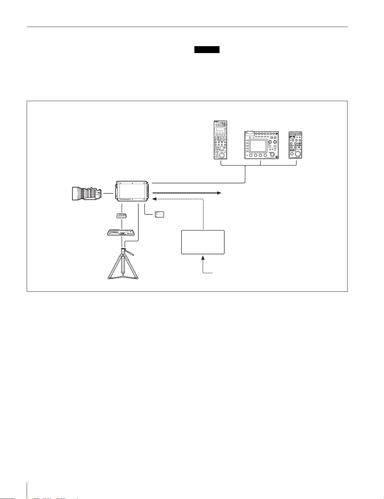
System Configuration
Peripherals and related devices for the camera are shown in
figures.
Standalone operation example
Zoom Lens
(for ENG/EFP)
V shoe
Tripod adaptor
VCT-14
Tripod for portable
camera
HDC-P1
“Memory Stick Duo”
Caution
Production of some of the peripherals and related devices
shown in the figures has been discontinued. For advice on
choosing devices, please contact your Sony dealer or a Sony
sales representative.
Remote Control Panel
RCP-700/900-series
CCA-5 cable
AC adaptor
AC-DN10
Video output
HD-SDI/SD-SDI
2)
VBS
AC power
Remote Control Unit
RM-B750/B150
2)
(selectable)
1) Menu settings cannot be configured
with the RM-B750/B150 Remote
Control Unit.
2) No subcarrier phase-lock function
with respect to external reference is
available for the VBS signal output
from the camera.
1)
6
Overview
Page 7
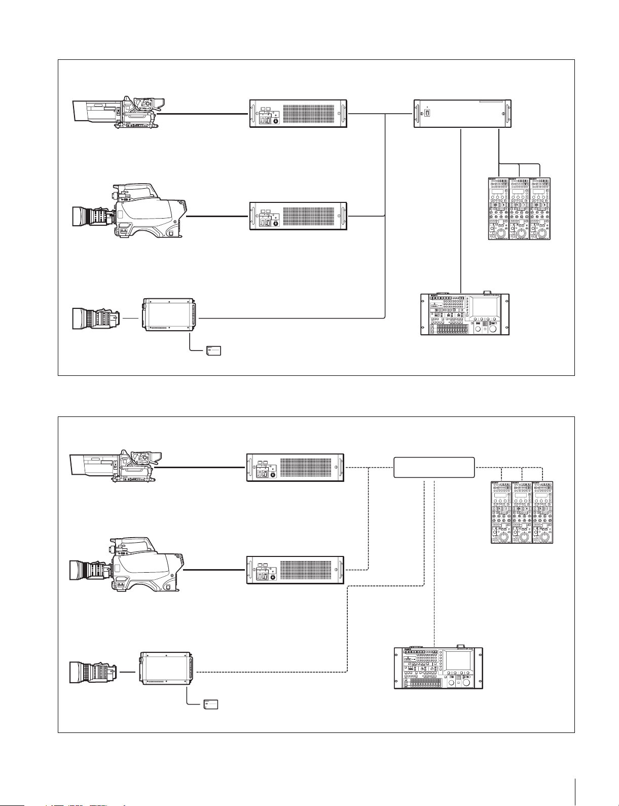
System operation example (camera command network unit)
HDC1000R
Optical fiber
cable
Camera Control Unit
HDCU1000/1500
Camera Command
Network Unit
CNU-700
CCA-5 cable
HDC1500R/1400R
Zoom Lens
(for ENG/EFP)
Optical fiber
cable
HDC-P1
“Memory Stick Duo”
Camera Control Unit
HDCU1000/1500
CCA-5 cable
MSU-900/950 Master
Setup Unit
System operation example (LAN)
For details on the camera settings, see “Configuring Control System Connection Settings” (page 12).
HDC1000R
Optical fiber
cable
Camera Control Unit
HDCU1000/1500
Hub
CCA-5 cable
Remote Control Panel
RCP-700/900-series
LAN cable
HDC1500R/1400R
Zoom Lens
(for ENG/EFP)
HDC-P1
“Memory Stick Duo”
Optical fiber
cable
Camera Control Unit
HDCU1000/1500
LAN cable
LAN cable
MSU-900/950 Master
Setup Unit
Remote Control Panel
RCP-700/900-series
LAN cable
Overview
7
Page 8
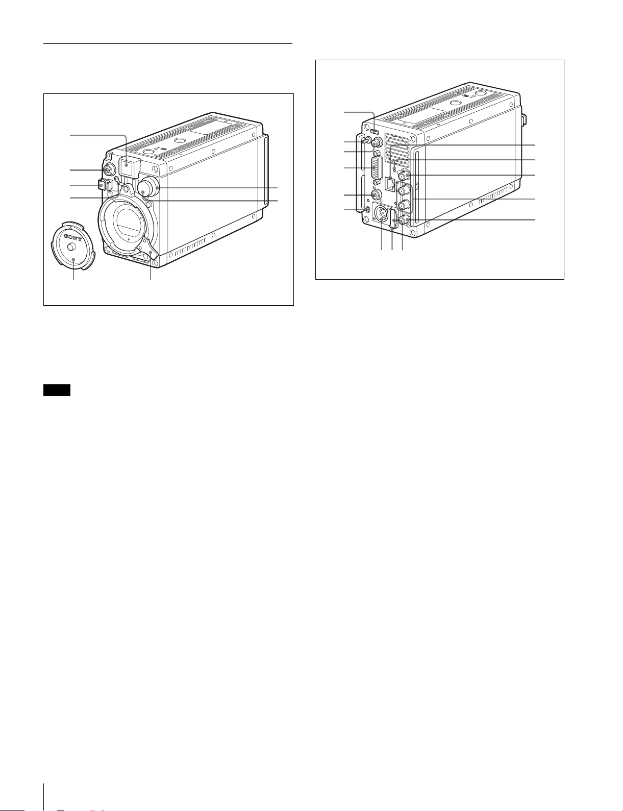
Parts Identification
89
7
Front
Rear
1
1
2
3
4
56
7
8
a Front tally lamp
The tally lamp lights when a call signal is generated in
response to the pressing of a CALL button or a tally signal
input to the EXT I/O connector.
You can attach the supplied number plate to display the
camera number.
Note
The front tally function cannot be operated during a battery
alarm operation.
b LENS connector (12-pin)
Connect the cable of the lens. The camera can control the lens
functions through this cable.
Connect the lens cable so that v is at the top.
c Lens cable clamp
To secure the cable of the lens (optional).
d Lens mount safety rubber
After attaching a lens, attach the rubber to prevent the lens
from coming loose.
Before removing the lens, remove this rubber from the boss on
the front panel.
e Lens mount cap
The cap can be removed by moving the lens fixing lever
upward.
Always keep the lens mount covered with this cap when a lens
is not attached.
f Lens fixing lever
Move the lever down to secure the lens in the lens mount.
g CC filter select knob
To select the built-in CC filters (A: cross, B: 3200K, C: 4300K,
D: 6300K).
h ND filter select knob
To select the built-in ND filters (1: clear, 2: 1/4 ND, 3: 1/16 ND,
4: 1/64 ND).
2
3
4
5
6
0
qa
qs
qd
qf
a Rear tally lamp
The tally lamp lights when a call signal is generated in
response to the pressing of a CALL button or a tally signal
input to the EXT I/O connector.
The rear tally lamp also serves as a battery alarm function.
If the voltage of the battery connected to the camera
decreases, the rear tally lamp flashes, and if the limit becomes
close to being reached, the rear tally lamp switches to highspeed flashing.
The alarm voltage for starting flashing can be set in the
BEFORE END item of the BATTERY ALARM page on the
MAINTENANCE menu, and the alarm voltage for switching to
high-high speed flashing can be set in the END item.
If a call signal is generated while the battery alarm function is
operating, the rear tally lamp goes out. Furthermore, the front
tally function becomes inoperable, so replace the battery.
If you want to give priority to the tally function and call function,
set the BATTERY ALARM item of the BATTERY ALARM page
on the MAINTENANCE menu to OFF.
For details, see “MAINTENANCE Menu” (page 24).
b DISPLAY/MENU switch
Select the display on the monitor screen.
DISPLAY: To display various textual information and markers,
such as messages showing the camera settings and
operating status, the center marker, and the safety zone
marker, in addition to camera images.
z (OFF): To not display textual information and markers.
MENU: To display menus for camera settings, in addition to
camera images.
c Menu control knob (rotary encoder)
Used to select settings from menus displayed on the monitor
screen (by rotating it) and to confirm settings (by pushing it).
d EXT I/O (external input/output) connector (D-sub, 15-
pin)
Connect an external device.
8
Overview
Page 9
e REMOTE connector (8-pin)
For connection to an RM-B150/B750 Remote Control Unit,
RCP-700/900-series Remote Control Panel, or MSU-900/950
Master Setup Unit.
f CAMERA POWER switch and indicator
To turn the power ON/OFF.
ON: Set the switch to the ? side.
OFF: Set the switch to the 1 side.
The indicator lights in green when the power is turned ON.
g DC IN (DC power supply input) connector (XLR 4-pin)
For connection to an AC-DN10 AC Adaptor, etc. to supply
power to the camera.
h “Memory Stick Duo” slot and access lamp
When you insert a “Memory Stick Duo” into the slot, the
access lamp lights in green.
The lamp is lit in red while writing/reading data to/from the
“Memory Stick Duo.”
Caution
• Only a “Memory Stick” of Duo size can be used with the
camera.
• When the access lamp is lit in red, do not insert/remove the
“Memory Stick Duo” or turn off the camera.
i “Memory Stick” cap
Remove the cap before inserting a “Memory Stick Duo.”
Caution
Do not use excessive force to pull the “Memory Stick” cap.
j (LAN) connector (RJ-45 type, 8-pin)
To connect to a LAN. Use a LAN cable (shielded, category 5
or above) to connect to the hub of the LAN (10BASE-T/
100BASE-TX).
CAUTION
• For safety, do not connect the connector for peripheral
device wiring that might have excessive voltage to this port.
Follow the instructions for this port.
• When you connect the LAN cable of the unit to peripheral
device, use a shielded-type cable to prevent malfunction due
to radiation noise.
ATTENTION
Par mesure de sécurité, ne raccordez pas le connecteur pour
le câblage de périphériques pouvant avoir une tension
excessive à ce port. Suivez les instructions pour ce port.
VORSICHT
Aus Sicherheitsgründen nicht mit einem PeripheriegerätAnschluss verbinden, der zu starke Spannung für diese
Buchse haben könnte. Folgen Sie den Anweisungen für diese
Buchse.
k NETWORK indicator
To indicate the state when connected to a network system.
Lit: Successfully connected to an external control device
(MSU-900 series master setup unit, RCP-900 series
remote control panel, etc.).
Flashing: Unable to connect to an external control device
(MSU-900 series master setup unit, RCP-900 series
remote control panel, etc.) properly.
Off: A LAN cable is not connected or the connection settings
of the network system are not configured.
For details on the adjustment, see “Configuring Control
System Connection Settings” (page 12), “MAINTENANCE
Menu” (page 24), “DIAGNOSIS Menu” (page 28).
l GENLOCK (external sync signal input) connector
(BNC type)
To input an external sync signal (BB or 3-level sync) to
synchronize the camera.
Note
Even when a BB signal is used for the external sync signal, no
subcarrier phase-lock function is available for the VBS output
signal.
m SDI 1 (serial digital interface) connector and SDI 2
connector (BNC type)
For HD-SDI or SD-SDI signal output.
HD-SDI signal and SD-SDI signal output can be selected on
the menu. (It is not possible to select an HD-SDI signal and
SD-SDI signal separately for the SDI 1 connector and SDI 2
connector. One or the other needs to be selected.)
Note
The functions that can be displayed differ depending on the
output settings.
For details on the adjustment, see “Connector Output Settings
and Display Functions” (page 9).
n VBS connector (BNC type)
To output a VBS signal.
Caution
• The VBS output signal has no subcarrier phase-lock
function with respect to external sync signals.
• The functions that can be displayed differ depending on the
output settings.
For details on the adjustment, see “Connector Output Settings
and Display Functions” (page 9).
Connector Output Settings and Display
Functions
The functions that can be displayed differ depending on the
connector output settings.
Connector
name
SDI 1 HD/SD No No No No No
SDI 2 HD
VBS SD
1) The focus assist functions include the VF DETAIL function and
FOCUS ASSIST INDICATOR function.
2) Linked to the DISPLAY/MENU switch setting.
3) A function can be set to ON/OFF on the OPERATION menu.
Output
setting
SD
Setting
Menus
2)
Ye s
2)
Ye s
2)
Ye s
Display functions
Operation
status
Ye s
Ye s
Ye s
Marker Zebra Focus
2)
Ye s
2)
No No No
2)
No No No
1)
assist
3)
Ye s
3)
Ye s
3)
Overview
9
Page 10
Installation
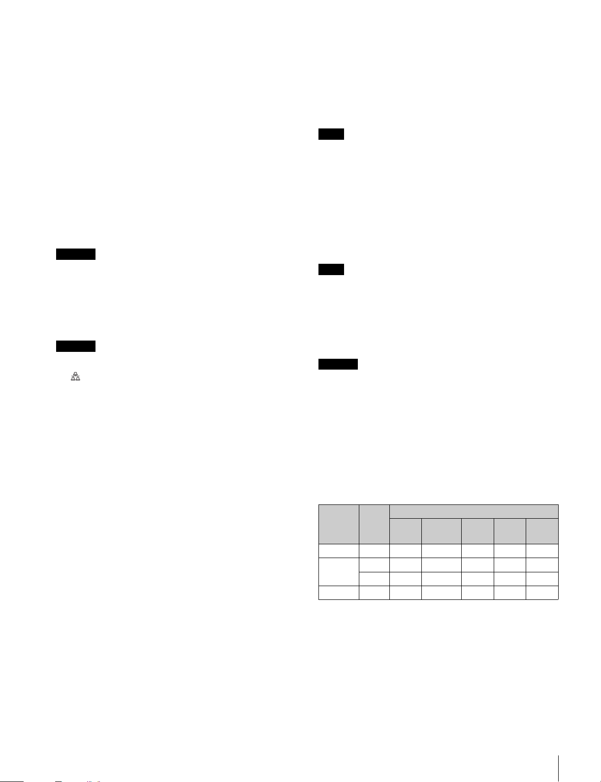
Attaching a Lens
For information on handling lenses, refer to the operation
manual for the particular lens
B
A
1
C
3
2
4
5
1 Remove the lens mount safety rubber, and then push
the lens fixing lever A upward and remove the lens
mount cap from the lens mount.
2 Align the lens’ alignment pin C with the notch B in
the upper part of the lens mount and insert the lens
into the mount.
3 While supporting the lens, push the lens fixing lever
A downward to secure the lens.
4 Connect the lens cable to the LENS connector.
5 Secure the lens cable with the cable clamp.
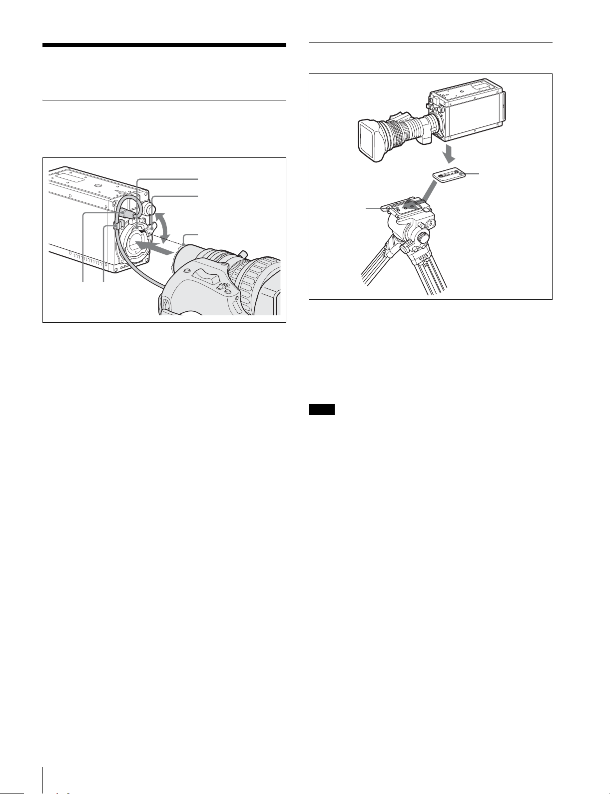
Mounting the Camera to a Tripod
1
Tripod attachment
2
Platform
adapter
1 Attach the tripod attachment adapter directly to the
camera.
(Two 3/8-inch tripod screws: screw depth of 10 mm
(13/32 inches) or less)
2 Place the camera on the tripod and mount the camera
by sliding it forward along the groove of the platform
until it clicks into place.
Note
If the screws of the tripod attachment adapter are 1/4-inch
tripod screws, use inch conversion screws (Sony Part No.: 4170-419-02) to attach the adapter. For details on purchasing
inch conversion screws, and other information, contact a Sony
service representative or Sony sales representative.
6 Reattach the lens mount safety rubber.
Installation
10
Page 11
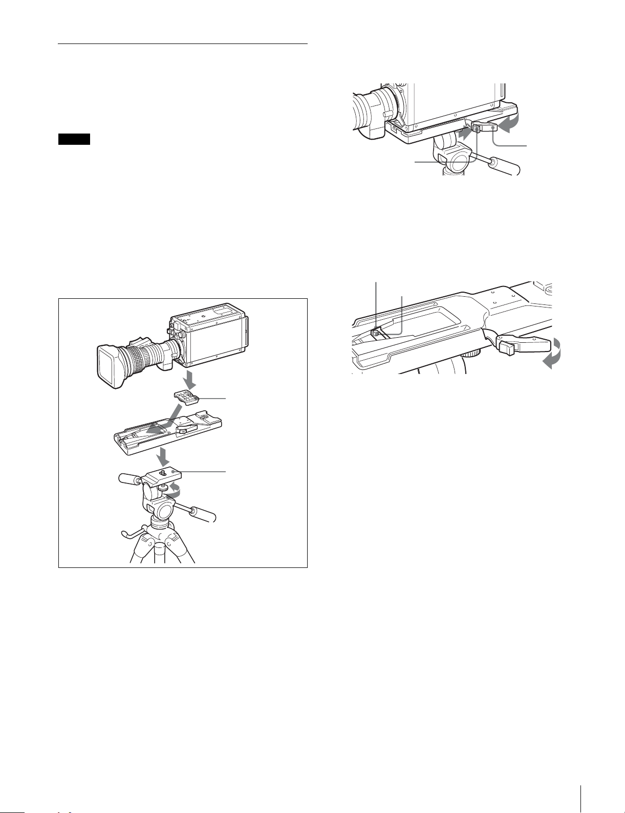
Mounting the Camera to a Tripod (When Using V Shoe and Tripod Adapter VCT-14)
Use a separately sold V shoe (Sony Part No.: A-8279-993-C)
and tripod adapter VCT-14 to mount the camera to the tripod.
To remove the camera from the tripod adaptor
Hold down the red button and pull the lever in the direction of
the arrow.
Notes
• Select an appropriate hole from among those at the bottom
of the tripod adaptor considering the balance of the weight
of the camera and the tripod adaptor. If an inappropriate
hole is selected, the camera may fall over.
• Check that the size of the selected hole matches that of the
screw of the tripod. If they do not match, the tripod adaptor
cannot be attached to the tripod securely.
• Use the following screws when attaching a separately sold
V shoe.Attachment screws: Four Alok + K4 × 8 screws
(Sony Part No.: 3-729-072-02)
Do not use screws that are 5 mm or longer for the camera.
For details on purchasing parts, contact a Sony service
representative or Sony sales representative.
1
V shoe
3
Tripod adaptor
Lever
Red button
If the pin of the tripod adaptor does not return to its
original position
After removing the camera, if the pin of the tripod adaptor does
not return to its original position, hold down the red button and
move the lever in the direction of the arrow to return the pin to
its original position. It is not possible to mount a camera with
the pin not seated.
Original position
Pin
1
2
Platform
2
1 Attach the V shoe to the camera with the attachment
screws.
2 1Attach the tripod adaptor to the tripod and 2
secure it with the screw.
3 Place the camera on the tripod adaptor and slide
forward it along the groove of the tripod adaptor until
it clicks.
Installation
11
Page 12

Preparatory Settings
7 When the date/time setting is completed, set the
DISPLAY/MENU switch to OFF to exit Menu mode.
Setting the Camera Outputs
Setting the Local Time
When the camera is used for the first time, display the
MAINTENANCE menu on the monitor connected to the VBS
connector or SDI 2 connector and set the built-in clock to the
current local time on the <DATE> page.
For details on menu operations, see “Menus” (page 16).
1 Turn on the camera.
2 While holding the menu control knob pressed, set the
DISPLAY/MENU switch to MENU.
The camera enters Menu mode, and “TOP” is displayed at
the upper-right corner of the screen.
3 Rotate the menu control knob to set the cursor to
“TOP” and push on the menu control knob.
The TOP MENU screen is displayed.
<TOP MENU>
USER
USER MENU CUSTOMIZE
ALL
OPERATION
PAINT
MAINTENANCE
FILE
DIAGNOSIS
4 Rotate the menu control knob to position the cursor
to MAINTENANCE and push on the menu control
knob.
The CONTENTS page of the MAINTENANCE menu is
displayed.
CONTENTS M00 TOP
01.<AUTO SETUP>
02.<WHITE SHADING>
03.<BLACK SHADING>
04.<OHB MATRIX>
05.<AUTO IRIS>
06.<TALLY>
07.<OUTPUT FORMAT>
08.<DOWN CONVERTER>
09.<VBS OUT>
10.<SDI OUT>
You can specify video signals output from the camera, with
menu operations.
Setting the output of SDI 1/2
Menu page title Setting Output
<SDI OUT> M10 HD-SDI HD-SDI
SD-SDI SD-SDI
Notes
• It is not possible to set the signals separately for the SDI 1
connector and SDI 2 connector.
• The functions that can be displayed differ depending on the
connector output settings.
For details on the adjustment, see “Connector Output Settings
and Display Functions” (page 9).
Configuring Control System Connection Settings
There are the following three modes for the control system of
the camera.
• LEGACY mode: This setting mode is for when controlling
the camera from an external control device via the REMOTE
connector of the camera.
• BRIDGE mode: This setting mode is for when controlling the
camera from an external control device via the LAN
connector of the camera on a one-to-one basis.
• MCS mode: This setting is for when building a multiplecamera system using multiple network compatible devices.
Use the MAINTENANCE menu to set the mode.
For details on menu operations, see “Menus” (page 16).
Note
When the control system connection mode is changed, turn
the power of all devices in the system off and then back on.
5 Turn the menu control knob to scroll the page and
position the pointer to <DATE> then push on the
menu control knob.
The <DATE> page is displayed.
<DATE> M16 TOP
DATE/TIME
2009/12/23 08:32
6 Turn the menu control knob and set the date and time.
Push on the menu control knob to shift to the next digit.
Preparatory Settings
12
To connect in LEGACY mode
Set CNS MODE to LEGACY.
For details, see “CNS SETTINGS (MAINTENANCE menu)”
(page 14).
Note
When a LAN cable will not be connected directly to the camera
even when building a camera network system using a LAN, set
CNS MODE to the LEGACY mode.
To connect in BRIDGE mode
1 Set CNS MODE to BRIDGE.
For details, see “CNS SETTINGS (MAINTENANCE
menu)” (page 14).
Page 13

2 Configure settings related to TCP/IP.
For details, see “TCP/IP SETTING (MAINTENANCE
menu)” (page 13).
About the menu to configure the control
system connection settings
For details on menu operations, see “Menus” (page 16).
3 Set the LAN connection.
For details, see “LAN SETTINGS (MAINTENANCE
menu)” (page 13).
4 Set the IP address of the camera for “target IP
address” of the MSU or RCP to be connected to the
LAN.
For details, see the operation manual of the MSU or RCP.
Note
The BRIDGE mode does not support a multiple-camera
system.
To connect in MCS mode
In MCS mode, one MSU that can be called the master is
required.
If there are multiple MSUs, set one of them to “master,” and the
others to “client.”
1 Set CNS MODE to MCS.
For details, see “CNS SETTINGS (MAINTENANCE
menu)” (page 14).
2 Set CCU NO.
For details, see “CNS SETTINGS (MAINTENANCE
menu)” (page 14).
3 Set MASTER IP ADDRESS.
For details, see “CNS SETTINGS (MAINTENANCE
menu)” (page 14).
4 Configure settings related to TCP/IP.
For details, see “TCP/IP SETTING (MAINTENANCE
menu)” (page 13).
5 Set the LAN connection.
For details, see “LAN SETTINGS (MAINTENANCE
menu)” (page 13).
6 Configure the settings of the MSU or RCP to be
connect by LAN.
For details, see the operation manual of the MSU or RCP.
Notes
• When connecting the RCP to the camera with a CCA-5
cable, and using a LAN cable for the connection device of
that RCP, set CNS MODE to the LEGACY mode.
• When connecting the RCP to the camera with a LAN cable,
and using a CCA cable for the connection device of that
RCP, set CNS MODE to the MCS mode.
• Set CCU NO to a number that is not a duplicate of any of the
CCU device numbers in the system.
TCP/IP SETTING (MAINTENANCE menu)
<TCP/IP SETTING> M15 TOP
IP ADDRESS:
0. 0. 0. 0
SUBNET MASK:
0. 0. 0. 0
DEFAULT GATEWAY:
0. 0. 0. 0
SET
IP ADDRESS: Set the IP address to assign to the camera.
SUBNET MASK: Set the subnet mask of the network
environment.
DEFAULT GATEWAY: Set the default gateway of the network
environment if necessary.
LAN SETTINGS (MAINTENANCE menu)
<LAN SETTINGS> M16 TOP
AUTO NEGOTIATION : ON
CONNECTION SPEED : 100M
DUPLEX MODE : FULL
AUTO MDI/MDIX : ON
MDI/MDIX : MDI
SET
AUTO NEGOTIATION: The LAN interface of the camera
supports Auto Negotiation. If the connected device
supports Auto Negotiation, setting this to ON will
automatically set the connection speed (SPEED) and
communication system (DUPLEX) in accordance with the
connected device. If the connected device does not
support Auto Negotiation, set this to OFF.
CONNECTION SPEED: Set the connection speed of the LAN
line. If AUTO NEGOTIATION is set to OFF, set this
manually (10M or 100M) in accordance with the connected
device.
DUPLEX MODE: Set the communication system of the LAN
line. If AUTO NEGOTIATION is set to OFF, set this
manually (half duplex: HALF or full duplex: FULL) in
accordance with the connected device.
AUTO MDI/MDIX: Set the automatic setting function for the
polarity of the connector of the LAN cable to be connected.
This setting is only enabled when AUTO NEGOTIATION is
set to ON.
MDI/MDIX: Set the polarity of the connector of the LAN cable
to be connected. When AUTO NEGOTIATION or AUTO
MDI/MDIX is set to OFF, manually set the polarity (MDI or
MDIX) in accordance with the connected device and cable.
Preparatory Settings
13
Page 14

CNS SETTINGS (MAINTENANCE menu)
<CNS SETTINGS> M17 TOP
CNS MODE : LEGACY
CCU NO : 0
MASTER IP ADDRESS:
0. 0. 0. 0
SET
2 Place a flange focal length adjustment chart
approximately 3 meters from the camera and adjust
the lighting to get an appropriate video output level.
About 3 meters
(10 ft)
CNS MODE: Sets the control system connection mode.
LEGACY: Sets the mode to the LEGACY mode.
BRIDGE: Sets the mode to the BRIDGE mode.
MCS: Sets the mode to the MCS mode.
CCU NO: Set the device number (camera number) of the
camera when using the MCS mode. Set a number that is
not a duplicate of any of the CCU device numbers in the
system.
MASTER IP ADDRESS: Set the IP address of the master
device for MCS mode.
Resetting the network configuration
information
<NETWORK RESET> M18 TOP
NETWORK ALL RESET
NETWORK ALL RESET: Restore the network related
information to the default state.
Adjusting the Flange Focal Length
Adjustment of the flange focal length (the distance between
the lens mount attachment plane and the imaging plane) is
necessary in the following situations:
• The first time a lens is attached
• When changing lenses
• If the focus is not sharp at both telephoto and wide angle
when zooming
The flange focal length can be more precisely adjusted by
using the focus assist indicators.
See “Displaying the focus assist indicators” (page 15) for the
focus assist indicators.
3 Loosen the Ff (flange focal length) ring lock screw.
4 With either manual or power zoom, set the zoom ring
to telephoto.
5 Aim at the flange focal length adjustment chart and
turn the focus ring to focus the image.
6 Set the zoom ring to wide angle.
7 Turn the Ff ring to bring the chart into focus.
Take care not to move the distance ring.
8 Repeat steps 4 through 7 until the image is in focus at
both telephoto and wide angle.
9 Tighten the Ff
ring lock screw.
Setting the Focus Assist Function
Using the OPERATION menu, the assist functions for easier
focusing on the monitor screen can be activated.
Note
When using the focus assist functions, connect a monitor to
the SDI 2 connector and set camera output to HD-SDI.
For details on the adjustment, see “Setting the Camera
Outputs” (page 12).
Adding a VF detail signal
Adding a VF detail signal to sharp edges in the image on the
monitor screen makes it easier to check the focusing condition
by observing changes in the detail signal or in the color
converted from the detail signal (color detail).
The focus setting where the detail signal becomes strongest is
the best focus setting.
1 Turn on the camera.
Note
The various parts of the lens used in adjusting the flange focal
length are in different positions on different lenses. Refer to the
operation manual for the lens.
1 Set the iris control to manual and open the iris fully.
Preparatory Settings
14
2 Set the DISPLAY/MENU switch to MENU while holding
the menu control knob pressed.
The camera enters Menu mode, and “TOP” is displayed at
the upper right corner of the screen.
Page 15

3 Rotate the menu control knob to align the pointer to
“TOP” and push on the knob.
The TOP MENU screen is displayed.
<TOP MENU>
USER
USER MENU CUSTOMIZE
ALL
OPERATION
PAINT
MAINTENANCE
FILE
DIAGNOSIS
4 Rotate the menu control knob to align the pointer to
OPERATION and push on the knob.
The CONTENTS page of the OPERATION menu is
displayed.
CONTENTS 00 TOP
01.<VF DISPLAY>
02.<VF MARKER>
03.<VF DETAIL>
04.<FOCUS ASSIST>
05.<ZEBRA>
06.<CURSOR>
07.<OPERATOR FILE>
08.<LENS FILE>
5 Rotate the menu control knob to align the pointer to
<VF DETAIL> and push on the knob
The <VF DETAIL> page is displayed.
<VF DETAIL> 03 TOP
VF DETAIL : ON 25%
CRISP : 0
FREQUENCY: 9M
FLICKER : OFF
AREA : 70%
ZOOM LINK: 100%
COLOR DETAIL : ON BLUE
PEAK COLOR : ON
CHROMA LEVEL: 100%
6 Rotate the menu control knob to align the pointer to
the item to be set and push on the knob.
To use the VF detail signal
Set VF DETAIL to ON to activate the VF detail function to
add the detail signal to sharp edges in the image. You can
adjust the signal level (strength) in the range of 0 to 100%
(default: 25%).
You can adjust the characteristics of the detail signal with
the menu items below:
CRISP: Adjust to eliminate fine portions of the detail
signal.
FREQUENCY: Change the detection band of sharp
edges.
FLICKER: Set the function for flickering the detail signal
to ON/OFF. (Setting the function to ON makes it easier
to check the detail signal on a CRT screen.)
AREA: To limit the area where to display the detail signal.
ZOOM LINK: Set the VF detail level at the full WIDE
position. (The VF detail level changes according to the
zoom position. The default setting is 100% with no
change at the full WIDE position. It becomes half at
50%.)
To use the color detail
Set COLOR DETAIL to ON to convert the VF detail signal
to a specified color. The display color can be selected in
the column on the right of ON.
You can adjust the coloring with the menu items below:
PEAK COLOR: Turn the function ON/OFF to change the
color where the detail signal is strongest.
CHROMA LEVEL: To reduce the chroma components of
the video signal.
7 Rotate the menu control knob to display the desired
setting and push on the knob.
8 To finish the adjustments, set the DISPLAY/MENU
switch to OFF to exit Menu mode.
Displaying the focus assist indicators
The focus assist indicator function extracts the irregularities of
a subject and converts the integrated values to a level
indicator, which shows the focus condition.
Level indicator (Its position and operations can be adjusted.)
Area marker to display the detection area of the
focus (Its size and position can be adjusted.)
The focus setting where the indicator shows the maximum
level is the best focus setting. (The range of the indicator
substantially changes depending on the picture elements or
shooting environment. Adjust it with GAIN and OFFSET as
necessary.)
1 Display the CONTENTS page of the OPERATION
menu (referring to step 1 to 4 in “Adding a VF detail
signal”).
2 Rotate the menu control knob to align the pointer to
<FOCUS ASSIST> and push on the menu control
knob.
The <FOCUS ASSIST> page is displayed.
<FOCUS ASSIST> 04 TOP
INDICATOR : OFF
MODE : BOX BOTTOM
LEVEL : 3 QUICK
GAIN : 50
OFFSET : 50
AREA MARKER: ON
SIZE : MIDDLE
POSITION : CENTER
POSITION H: 50
POSITION V: 50
Preparatory Settings
15
Page 16

3 Rotate the menu control knob to align the pointer to
the item to be set and push on the knob.
To use the level indicator
Setting INDICATOR to ON displays the level indicator on
the monitor. You can set the display format with the menu
items below.
MODE: Set the type and position of the indicator.
LEVEL: Set the density and the response speed of the
indicator.
GAIN: Set the sensitivity of the indicator.
OFFSET: Set the offset of the focus detection value.
1) Normally, the sensitivity of the indicator is automatically set to
the optimum value in conjunction with the AREA MARKER
SIZE set value. Use this setting when an optimum sensitivity
value cannot be obtained, depending on the shooting
environment.
2) Normally, the optimum offset is automatically set in conjunction
with the AREA MARKER SIZE and MASTER GAIN set values.
Use this setting when the optimum offset cannot be obtained,
depending on the shooting environment.
1)
2)
To use the area marker
Setting AREA MARKER to ON displays the detection area
of the focus as a marker on the monitor.
You can set the size and position of the detection area with
the menu items below.
SIZE: The size of the detection area can be changed. (If
the area size is too large, both the subject and the
background are included in the area, making the
indicator display easily deviate from the subject.)
POSITION: Roughly set the position of the detection area.
POSITION H: Finely adjust the position of the detection
area in the horizontal directions.
POSITION V: Finely adjust the position of the detection
area in the vertical directions.
4 Rotate the menu control knob to display the desired
setting and push on the knob.
5 To finish the adjustments, set the DISPLAY/MENU
switch to OFF to exit Menu mode.
Notes
• The INDICATOR and effect area marker cannot be
displayed at the same time. The one that was set to ON last
takes priority.
• The AREA MARKER and aspect safety marker cannot be
displayed at the same time. The one that was set to ON last
takes priority.
• When displaying the focus assist indicators, check that the
flange focal length has been precisely adjusted.
See “Adjusting the Flange Focal Length” (page 14) for the
flange focal length.
Menus
The menus displayed on the monitor connected to the VBS
connector or SDI 2 connector enable various settings of the
camera to be configured.
The following controls are used to operate the menus.
Turn the menu control knob on the rear panel to select menu
items or values, and push on it to register (enter) the selection.
Rear
DISPLAY/MENU switch
Menu control knob
Rotate
Push on
Displaying Menu Pages
To display a menu page
Set the DISPLAY/MENU switch to MENU.
The menu page last accessed will be displayed. If it is the first
time, the CONTENTS page of the USER menu will be
displayed.
To display the TOP MENU screen
If you set the DISPLAY/MENU switch to MENU while holding
the menu control knob pressed, “TOP” is displayed at the
upper right corner of the screen.
Turn the menu control knob to move the pointer on the display
to “TOP” and push on the knob. The TOP MENU screen is
displayed, listing the available menus.
<TOP MENU>
USER
USER MENU CUSTOMIZE
ALL
OPERATION
PAINT
MAINTENANCE
FILE
DIAGNOSIS
Menu Purpose
USER This menu can include menu pages selected
USER MENU
CUSTOMIZE
from among the OPERATION, PAINT,
MAINTENANCE, FILE, and DIAGNOSIS menus,
for convenience (see the table on page 18 for the
default configuration). Changing, adding, and
deleting pages can be performed with the USER
MENU CUSTOMIZE menu.
This menu allows you to edit the USER menu.
For details, see “Editing the USER Menu” (page
18).
16
Menus
Page 17

Menu Purpose
ALL This menu permits you to control all items of the
OPERATION This menu contains items for camera operators
PAINT This menu contains items for making detailed
MAINTENANCE This menu contains items for performing camera
FILE This menu is for performing file operations, such
DIAGNOSIS This menu enables you to confirm the self-
OPERATION menu, PAINT menu,
MAINTENANCE menu, FILE menu, and
DIAGNOSIS menu as a single menu.
to operate the camera. It mainly permits switch
settings.
image adjustments while using a waveform
monitor to monitor the waveforms output from the
camera. Support of a video engineer is usually
required to use this menu.
Although you can also use an external control
device to set the items on this menu, the menu is
effective when using the camera by itself
outdoors.
maintenance operations, such as changing the
system or setting infrequently used “paint” items.
as writing or clearing the reference file.
diagnostic information.
To disable the “TOP” indication
Turn the power off then on again to disable the TOP selection.
Setting the Menu
To select a menu on the TOP MENU screen
Rotate the menu control knob to align the pointer with the
desired menu indication then push on the knob.
The CONTENTS page (page No. 00) or the last accessed
page of the selected menu is displayed.
To select a page from a CONTENTS page
Rotate the menu control knob to align the pointer (,) with the
desired page indication then push on the menu control knob.
If the screen can be scrolled, arrows will indicate
the direction for scrolling.
CONTENTS P00 TOP
01.<SW STATUS>
02.<VIDEO LEVEL>
Pointer
03.<COLOR TEMP>
04.<GAMMA>
05.<BLACK GAMMA>
06.<SATURATION>
07.<KNEE>
08.<WHITE CLIP>
09.<DETAIL 1>
10.<DETAIL 2>
To change the displayed page
1 Check that the pointer is located at the left of the page
number then push on the menu control knob.
The pointer changes to a flashing question mark.
flash
<GAMMA> ? P03 TOP
[R] [G] [B] [M]
LEVEL : 0 0 0 0
COARSE : 0.45
2 Rotate the menu control knob to flip through the
pages, and push on the knob when the desired page
is displayed.
The question mark will change back to the pointer, and
operations with the displayed page are enabled.
To return to the TOP MENU screen
Align the pointer with “TOP” at the top right of the menu
page then push on the menu control knob.
<GAMMA> P03 TOP
[R] [G] [B] [M]
LEVEL : 0 0 0 0
:
.
To set the Menu Items
If a question mark is flashing at the left of the page number,
push on the menu control knob to change it to the pointer (,).
Operation on the displayed page is enabled.
1 Align the pointer with the desired item, then push on
the menu control knob.
The pointer changes to a flashing question mark.
2 Rotate the menu control knob to change the setting
value.
When the knob is rotated quickly, the values will change
quickly; when rotated slowly, the values will change slowly.
To interrupt settings
Set the DISPLAY/MENU switch to OFF to turn off the
menu screen display.
The setting operation can be restarted by setting the
DISPLAY/MENU switch back to MENU.
3 Push on the menu control knob.
The question mark will change back to the pointer, and the
new setting will be registered.
4 To change other setting items on the same menu
page, repeat steps 1 through 3.
The selected page is displayed.
<GAMMA> P03 TOP
[R] [G] [B] [M]
LEVEL : 0 0 0 0
COARSE : 0.45
Page number
To specify a character string
When you press the menu control knob with the pointer
pointing to an item for which a character string, such as a file
ID, is to be specified, a cursor and the list of selectable
characters are displayed.
The displayed cursor can be moved by rotating the menu
control knob.
Menus
17
Page 18

1 Set the cursor to the position where you wish enter a
character, then push on the menu control knob.
Another cursor appears on the character list.
2 Set the cursor to the character to be entered and push
on the menu control knob.
Repeat steps 1 and 2.
• By selecting INS on the line below the character list, you
can enter a space at the cursor position.
• Selecting DEL deletes the character at the cursor
position.
• You can return to step 1 without changing the character
by selecting RET.
• If you enter the permitted maximum number of
characters (up to the stop mark at the right end of the
line), the cursor moves to ESC on the line below the
character list.
3 Select END and push on the menu control knob.
The new string you have set is registered.
To reset a changed value
Select ESC and push on the menu control knob.
For the items on each page, see “OPERATION Menu” (page
20), “MAINTENANCE Menu” (page 24), or “DIAGNOSIS
Menu” (page 28).
The USER MENU CUSTOMIZE menu allows you to configure
the USER menu as follows:
• Creating a new menu page and selecting and adding
(registering) items that you use very frequengly from
multiple menu pages.
• Deleting (unregistering) added items.
• Changing the order of added items.
• Adding (registering) a menu page (new page you create or
existing menu page) to the USER menu.
• Deleting (unregistering) a page from the USER menu.
• Changing the order of pages of the USER menu.
Editing at the item level
The USER MENU CUSTOMIZE menu allows you to create a
new page for the USER menu and add any item.
Initially, the EDIT page of the USER MENU CUSTOMIZE
already contains items but the USER 1 EDIT to USER 19 EDIT
pages are blank. Up to 10 items can be selected and
registered to these pages from different menu pages.
To end menu operations
Set the DISPLAY/MENU switch to OFF.
Restoring a setting to the default setting
When an item is selected and , is displayed, pressing and
holding the menu control knob for 3 seconds restores the
setting value to the state in the reference file. If 10 SECCLEAR
of the FILE CLEAR page on the FILE menu is set to ON,
pressing the control knob for another 10 seconds restores the
reference file value of the selected item to the default state.
Editing the USER Menu
You can select desired pages and items from the
OPERATION, PAINT, MAINTENANCE, FILE, and
DIAGNOSIS menus and register them to the USER menu.
If you specify pages or items frequently used for the USER
menu, you can easily call and use them.
The following pages are included on the factory-set USER
menu:
Menu page title USER
menu No.
<VF DETAIL> U01 OPERATION 03
<FOCUS ASSIST> U02 OPERATION 04
<VF DISPLAY> U03 OPERATION 01
<VF MARKER> U04 OPERATION 02
<CURSOR> U05 OPERATION 06
<ZEBRA> U06 OPERATION 05
<LENS FILE> U07 OPERATION 08
<OUTPUT FORMAT> U08 MAINTENANCE M07
<SDI OUT> U09 MAINTENANCE M10
<DOWN CONVERTER> U10 MAINTENANCE M08
<TALLY> U11 MAINTENANCE M06
<ROM VERSION> U12 DIAGNOSIS D03
Source menu/
page No.
To add items to a page
1 Select USER MENU CUSTOMIZE on the TOP MENU
screen (see page 16).
If this is the first time the USER MENU CUSTOMIZE
menu has been displayed, the CONTENTS page of the
menu appears.
CONTENTS E00
xx
01.EDIT PAGE
02.USER 1 EDIT
c
03.USER 2 EDIT
04.USER 3 EDIT
05.USER 4 EDIT
06.USER 5 EDIT
07.USER 6 EDIT
08.USER 7 EDIT
09.USER 8 EDIT
10.USER 9 EDIT
TOP
If the USER MENU CUSTOMIZE menu has been used
before, the page last accessed appears.
2 If the CONTENTS page is displayed, turn the menu
control knob to move the pointer to any of USER 1
EDIT to USER 19 EDIT then push on the menu control
knob to display the page.
If a different page is displayed, turn the menu control
knob until the desired page appears then push on the
menu control knob to select the page.
Example: When you select the USER 2 EDIT page
USER 2 EDIT E03cTOP
18
Menus
Page 19

3 Move the pointer to the item to be added (this
operation is unnecessary if no item exists on the
page, as shown in the figure for the previous step)
then push on the menu control knob.
The EDIT FUNCTION screen appears.
To delete items from a page
1 Move the pointer to the item to be deleted then push
on the menu control knob.
The EDIT FUNCTION screen appears.
EDIT FUNCTION
c
INSERT
MOVE
DELETE
BLANK
ESC
4 Move the pointer to INSERT and push on the menu
control knob.
The page with the last item added appears.
<SW STATUS> P01
FLARE :
GAMMA : ON
BLK GAM : OFF
KNEE : ON
WHT CLIP: ON
DETAIL : ON
LVL DEP : ON
SKIN DTL: OFF
MATRIX : OFF
c
ON
ESC
5 Add the items.
1 Turn the menu control knob until the page that has the
desired items appears, then push on the menu control
knob.
2 Turn the menu control knob to move the pointer to the
desired item, then push on the menu control knob.
The USER 2 EDIT page appears again, displaying the
newly added item.
6 Add the remaining items by repeating steps 3 to 5.
You can add up to 10 items on one page.
To change the order of items on a page
2 Select DELETE and push on the menu control knob.
The previously displayed page appears again, and the
message “DELETE OK? YES,NO” appears.
3 To delete, turn the menu control knob to move the
pointer to YES and push on the menu control knob.
To insert a blank line
1 Move the pointer to the item above which you wish to
insert a blank line.
The EDIT FUNCTION screen appears.
2 Select BLANK then push on the menu control knob.
The previously displayed page appears again, and a blank
line is inserted above the specified item.
Note
You cannot insert a blank line on a page where 10 items have
already been registered.
Editing at the page level
EDIT PAGE of the USER MENU CUSTOMIZE menu allows
you add, delete, and sort new pages and existing pages.
To add a page
1 Select USER MENU CUSTOMIZE on the TOP MENU
screen.
If this is the first time the USER MENU CUSTOMIZE
menu has been displayed, the CONTENTS page of the
menu appears.
If the USER MENU CUSTOMIZE menu has been used
before, the page last accessed appears.
1 Move the pointer to the item to be moved then push
on the menu control knob.
The EDIT FUNCTION screen appears.
2 Select MOVE then push on the menu control knob.
The previously displayed page appears again.
3 Move the pointer to the position where you wish to
move the page then push on the menu control knob.
ITEM MOVE
xx
c
VF DETAIL : ON
COLOR DETAIL : OFF
MARKER : ON
CURSOR : OFF
z
ZEBRA SW : OFF
: 1
The item selected in step 1 moves to the position that you
selected in step 3.
In the above example, ZEBRA SW is moved to the top,
and the other items are moved down one line.
ESC
2 If the CONTENTS page is displayed, turn the menu
control knob to move the pointer to EDIT PAGE then
push on the menu control knob to display the EDIT
PAGE screen.
If a different page is displayed, turn the menu control
knob until the EDIT PAGE screen appears then push
on the menu control knob to select the page.
EDIT PAGE E01
xx
01.<VF DETAIL>
c
02.<FOCUS ASSIST>
03.<VF DISPLAY>
04.<VF MARKER>
05.<CURSOR>
06.<ZEBRA>
07.<LENS FILE>
08.<OUTPUT FORMAT>
09.<SDI OUT>
10.<DOWN CONVERTER>
TOP
3 Move the pointer to the position where you wish to
add the page then push on the menu control knob.
The EDIT FUNCTION screen appears.
Menus
19
Page 20

4 Select INSERT then push on the menu control knob.
The selection screen appears.
CONTENTS
xx
c
01.USER 1
02.USER 2
03.USER 3
04.USER 4
05.USER 5
06.USER 6
07.USER 7
08.USER 8
09.USER 9
10.USER 10
ESC
5 Move the pointer to the desired page then push on the
menu control knob.
This adds the number and name of the selected page
above the item selected in step 3.
To cancel addition of a page
Before pushing the menu control knob in step 5, turn the
menu control knob to move the pointer to ESC at the top
right of the screen then push on the menu control knob.
The EDIT PAGE screen appears again.
To delete a page
1 On the EDIT PAGE screen of the USER MENU
CUSTOMIZE menu, move the pointer to the page to be
deleted and push on the menu control knob.
The EDIT FUNCTION screen appears.
2 Select DELETE and push on the menu control knob.
The previously displayed page appears again, and the
message “DELETE OK? YES,NO” appears.
ITEM DELETE
DELETE OK? YES
01.<VF DETAIL>
02.<FOCUS ASSIST>
03.<VF DISPLAY>
z
04.<VF MARKER>
05.<CURSOR>
06.<ZEBRA>
07.<LENS FILE>
08.<OUTPUT FORMAT>
09.<SDI OUT>
10.<DOWN CONVERTER>
ESC
c
NO
3 To delete, turn the menu control knob to move the
pointer to YES and push on the menu control knob.
To change the order of pages
The item selected in step 1 moves to the position that you
selected in step 3. In the above example, <SDI OUT> moves
to 04, and <VF MARKER> and the following pages move down
one line.
OPERATION Menu
Note
These remarks are common for all the following menu tables.
ON, OFF, 0, ... , in the Settings columns: Default settings
Page No. nn (Unn): For the pages that have been registered on the
USER menu at the factory, the USER menu page numbers are
indicated in parenthesis.
Execute by ENTER: Execute by pushing on the menu control knob.
Page title
Page No.
<VF DISPLAY>
01 (U03)
Item Settings
EX ON
ZOOM ON, OFF
DISP LEFT, RIGT
FOCUS
Valid only when a
serial lens is
used
ND ON, OFF
CC ON
5600K (246 ft) ON
IRIS ON
WHITE ON, OFF
GAIN ON, OFF
SHUTT ON
BATT ON, OFF
MESSAG ALL, AT, WRN, OFF
, OFF
ON, OFF
, OFF
, OFF
, OFF
, OFF
ALL: To display all
messages
WRN: To display
warning messages
and higher
AT: To display Auto
Setup information and
higher
1 Display the EDIT PAGE screen of the USER MENU
CUSTOMIZE menu. Turn the menu control knob to
move the pointer to the page that you wish to move.
The EDIT FUNCTION screen appears.
2 Select MOVE then push on the menu control knob.
The EDIT PAGE screen appears again.
3 Move the pointer to the position where you wish to
move the page then push on the menu control knob.
20
Menus
ITEM MOVE
xx
01.<VF DETAIL>
02.<FOCUS ASSIST>
03.<VF DISPLAY>
c
04.<VF MARKER>
05.<CURSOR>
06.<ZEBRA>
07.<LENS FILE>
08.<OUTPUT FORMAT>
z
09.<SDI OUT>
10.<DOWN CONVERTER>
ESC
Page 21

Page title
Page No.
<VF MARKER>
02(U04)
<VF DETAIL>
03 (U01)
Item Settings
MARKER ON, OFF
WHITE, BLACK, DOT
CENTER ON, OFF
1, 2, 3, 4
1: Entire cross
2: Entire cross with a
hole
3: Center
4: Center with a hole
SAFETY ZONE ON, OFF
80.0, 90.0, 92.5, 95.0%
EFFECT ON, OFF
ASPECT ON, OFF
16:9, 15:9, 14:9, 13:9, 4:3
MASK ON, OFF
0 to 15 12
SAFETY
For the safety
marker in
Aspect mode
VF DETAIL ON, OFF
CRISP –99 to +99 0
FREQUENCY 9M, 14M, 18M
FLICKER ON, OFF
AREA 100%, 70%, 60%, 50%,
ZOOM LINK 0%, 25%, 50%, 75%,
COLOR DETAIL ON, OFF
PEAK COLOR ON, OFF
CHROMA
LEVEL
ON, OFF
80.0, 90.0
0 to 100% 25%
40%
100%
BLUE, RED, YELLOW
100%, 50%, 25%, 0%
, (FOCUS)
(FOCUS): Displayed
when INDICATOR of
<FOCUS ASSIST> is
ON.
Set the level to darken
outside the aspect area.
, (AREA)
(AREA): Displayed when
AREA MARKER of
<FOCUS ASSIST> is
ON.
, 92.5, 95.0%
Page title
Page No.
<FOCUS
ASSIST>
04 (U02)
<ZEBRA>
05 (U06)
<CURSOR>
06 (U05)
<OPERATOR
FILE>
07
See FILE menu
F01.
Item Settings
INDICATOR ON, OFF
MODE BOX
BOTTOM
RIGHT
LEVEL 1 to 5 3
QUICK, SMOOTH
GAIN 0 to 99 50
OFFSET 0 to 99 50
AREA MARKER ON, OFF, (ASPECT)
SIZE SMALL, MIDDLE
POSITION LEFT, CENTER
POSITION H 0 to 99 50
POSITION V 0 to 99 50
ZEBRA ON, OFF
1, 2, 1&2
ZEBRA1 LEVEL 50 to 109% 70
WIDTH 0 to 30% 10
ZEBRA2 50 to 109% 100
CURSOR ON, OFF
WHITE, BLACK, DOT
BOX/CROSS BOX
H POSITION 0 to 99 50
V POSITION 0 to 99 50
WIDTH 0 to 99 50
HEIGHT 0 to 99 50
READ (MStCAM) Execute by ENTER.
WRITE
(CAMtMS)
PRESET Execute by ENTER.
FILE ID Max.16 characters
CAM CODE Display only
DATE Display only
Execute by ENTER.
, (EFFECT)
EFFECT): Displayed
(
when EFFECT of <VF
MARKER> is ON.
, B&W, COL
, LEFT, TOP,
(ASPECT): Displayed
when ASPECT
SAFETY of <VF
MARKER> is ON.
, LARGE
, RIGHT
, CROSS
Menus
21
Page 22

Page title
Page No.
<LENS FILE>
08 (U07)
PAINT Menu
Page title
Page No.
<SW STATUS>
P01
<VIDEO
LEVEL>
P02
Item Settings
FILE 1 to 17
CENTER MARKER
To set and store the center marker position
H POS –20 to 20 0
V POS –20 to 20 0
STORE Execute by ENTER.
Item Settings
FLARE ON
GAMMA ON
BLK GAM ON, OFF
KNEE ON, OFF
WHT CLIP ON
DETAIL ON
LVL D E P ON
SKIN DTL ON, OFF
MATRIX ON, OFF
WHITE R/G/B: –99 to 99 0
BLACK R/G/B/M: –99 to 99 0
FLARE R/G/B: –99 to 99 0
GAMMA R/G/B/M: –99 to 99 0
V MOD R/G/B/M: –99 to 99 0
FLARE ON, OFF
V MOD ON
D. SHAD ON, OFF
TEST OFF
1 to 16: When using a
non-serial lens
1 to 17: When using a
serial lens
Lens file name
Changeable only when
using a non-serial lens
F-stop number of the lens
Changeable only when
using a non-serial lens
Increasing the value
moves it to the right.
Increasing the value
moves it downwards.
, OFF
, OFF
, OFF
, OFF
, OFF
, OFF
Selectable only when
using a dynamic
shooting compatible lens
, SAW, 3STEP,
10STEP
Page title
Page No.
<COLOR
TEMP>
P03
<GAMMA>
P04
<BLACK
GAMMA>
P05
<SATURATION>
P06
Item Settings
WHITE R/G/B: –99 to 99 0
AUTO WHITE
BALANCE
COLOR TEMP 0K to 65535K 3200K
BALANCE –99 to 99 0
AT W O N , OFF
SPEED 1 to 5 4
MASTER –3.0dB to 12.0dB 0.0dB
LEVEL R/G/B/M: –99 to 99 0
COARSE 0.35 to 0.45 to 0.90
TA BL E STANDARD
GAMMA ON
TEST OFF
LEVEL –99 to 99 0
RANGE LOW, L.MID, H.MID, HIGH
TEST OFF, SAW, 3 STEP,
SATURATION –99 to 99 0
LOW KEY SAT –99 to 99 0
RANGE LOW, L.MID, H.MID, HIGH
TEST OFF, SAW, 3 STEP,
Execute by ENTER.
(0.05 steps)
, HYPER
With STANDARD selected:
1, 2, 3, 4, 5
1: equivalent to a
2: 4.5-times gain
3: 3.5-times gain
4: equivalent to SMPTE-
5: equivalent to ITU-
6: 5.0-times gain
7: 5.0-times gain - 709
With HYPER selected:
1, 2, 3, 4
1: 325% to 100%
2: 460% to 100%
3: 325% to 109%
4: 460% to 109%
(When you change the
TABLE setting, noise may
be generated. This is not
malfunction.)
10 STEP
Master level only
ON, OFF
10 STEP
ON, OFF
ON, OFF
10 STEP
, 6, 7
camcorder
240M
R709
, OFF
, SAW, 3 STEP,
22
Menus
Page 23

Page title
Page No.
<KNEE>
P07
<WHITE CLIP>
P08
<DETAIL 1>
P09
<DETAIL 2>
P10
<SD DETAIL 1>
P11
<SD DETAIL 2>
P12
Item Settings
K POINT R/G/B/M: –99 to 99 0
K SLOPE R/G/B/M: –99 to 99 0
KNEE ON, OFF
KNEE MAX ON, OFF
KNEE SAT –99 to 99 0
ON, OFF
AUTO KNEE OFF, AUTO
POINT LIMIT –99 to 99 0
SLOPE –99 to 99 0
ABS When highlighted (ABS
W CLIP –99 to 99 0
ABS When highlighted (ABS
DETAIL ON
LEVEL –99 to 99 0
LIMITER [M] –99 to 99 0
LIMITER [WHT] –99 to 99 0
LIMITER [BLK] –99 to 99 0
CRISP –99 to 99 0
LVL DEP –99 to 99 0
ABS When highlighted (ABS
H/V RATIO –99 to 99 0
FREQ –99 to 99 0
MIX RATIO –99 to 99 0
KNEE APT –99 to 99 0
ABS When highlighted (ABS
SD DETAIL ON
LEVEL –99 to 99 0
LIMITER [M] –99 to 99 0
LIMITER [WHT] –99 to 99 0
LIMITER [BLK] –99 to 99 0
CRISPENING –99 to 99 0
LEVEL DEP –99 to 99 0
H/V RATIO –99 to 99 0
FREQUENCY –99 to 99 0
DETAIL COMB –99 to 99 0
mode): K POINT R/G/B, K
SLOPE R/G/B, and POINT
LIMIT are displayed in
absolute values.
ON, OFF
mode): W CLIP displayed
absolute values.
in
, OFF
ON, OFF
mode): LEVEL, LIMITER
WHT, LIMITER BLK,
CRISP, and LVL DEP are
displayed in
ON, OFF
mode): H/V RATIO, FREQ,
MIX RATIO, and KNEE
APERTURE are displayed
absolute values.
in
, OFF
absolute values.
Page title
Page No.
<SKIN DETAIL>
P13
<SD CROSS
COLOR>
P14
<USER
MATRIX>
P15
Item Settings
SKIN DTL ON, OFF
SKIN GATE ON, OFF, (MAT)
AUTO HUE Execute by ENTER.
PHASE 0
WIDTH 0 to 90 29
SAT –99 to 99 –89
LEVEL –99 to 99 0
ABS When highlighted (ABS
CRS COL REDUCE ON, OFF
LEVEL –99 to 99 0
CORING –99 to 99 0
R-G –99 to 99 0
R-B –99 to 99 0
G-R –99 to 99 0
G-B –99 to 99 0
B-R –99 to 99 0
B-G –99 to 99 0
MATRIX ON, OFF
PRESET ON, OFF, - -
USER ON, OFF
MULTI ON, OFF
(MAT): Displayed when
GATE of <MULTI
MATRIX> is ON.
to 359
mode): LEVEL is displayed
in an absolute value.
- - : When MATRIX OFF
(cannot be changed)
SMPTE-240M, ITU-709
SMPTE-WIDE, NTSC,
EBU, ITU-601, - -
- - : When MATRIX OFF
(cannot be changed)
, - -
- - : When MATRIX OFF
(cannot be changed)
, - -
- - : When MATRIX OFF
(cannot be changed)
,
Menus
23
Page 24

Page title
Page No.
<MULTI
MATRIX>
P16
<SHUTTER>
P17
<NOISE SUP>
P18
Item Settings
PHASE
Select an axis
(angle) for which
the multimatrix
adjustment to be
made.
HUE
Independently set
for 16 axes.
SAT
Independently set
for 16 axes.
ALL CLEAR Execute by ENTER.
GATE ON, OFF
MATRIX ON, OFF
PRESET ON, OFF, - -
USER ON, OFF
MULTI ON, OFF
SHUTTER ON, OFF
ECS FREQ 59.94i: 60.00
NOISE SUP 0 to 100%, 0%
, 23, 45, 68, 90, 113, 135,
0
158, 180, 203, 225, 248,
270, 293, 315, 338
–99 to 99 0
–99 to 99 0
The HUE and SAT
values for all PHASE
settings are cleared.
, (SKN)
(SKN): Displayed when
SKIN GATE of <SKIN
DETAIL> is ON.
- - : When MATRIX OFF
(cannot be changed)
SMPTE-240M, ITU-709
SMPTE-WIDE, NTSC,
EBU, ITU-601, - -
- - : When MATRIX OFF
(cannot be changed)
, - -
- - : When MATRIX OFF
(cannot be changed)
, - -
- - : When MATRIX OFF
(cannot be changed)
When 59.94i: 1/100, 1/125,
1/250, 1/500, 1/1000,
1/2000 (sec)
When 50i: 1/60, 1/125,
1/250, 1/500, 1/1000,
1/2000 (sec)
When 59.94P: 1/100,
1/125, 1/250, 1/500,
1/1000, 1/2000 (sec)
When 50P: 1/60, 1/125,
1/250, 1/500, 1/1000,
1/2000 (sec)
50i: 50.00 to 4700 Hz
59.94P: 59.96 to 4600 Hz
50P: 50.03 to 4600 Hz
ON, OFF
to 4300 Hz
Page title
Page No.
<SCENE FILE>
P19
See “FILE
menu” F02.
Item Settings
1 To store and read scene
2
3
4
5
STORE
STANDARD Execute by ENTER.
READ (MStCAM) Execute by ENTER.
WRITE
(CAMtMS)
FILE ID Max.16 characters
CAM CODE Display only
DATE Display only
files (paint data).
Execute by ENTER.
MAINTENANCE Menu
Page title
Page No.
<AUTO
,
SETUP>
M01
<WHITE
SHADING>
M02
<BLACK
SHADING>
M03
Item Settings
AUTO BLACK Execute by ENTER.
AUTO WHITE Execute by ENTER.
AUTO LEVEL Execute by ENTER.
AUTO WHITE
SHADING
AUTO BLACK
SHADING
TEST OFF
V SAW R/G/B: –99 to 99 0
V PARA R/G/B: –99 to 99 0
H SAW R/G/B: –99 to 99 0
H PARA R/G/B: –99 to 99 0
WHITE R/G/B: –99 to 99 0
AUTO WHITE
SHADING
WHITE SHAD
MODE
V SAW R/G/B: –99 to 99 0
V PARA R/G/B: –99 to 99 0
H SAW R/G/B: –99 to 99 0
H PARA R/G/B: –99 to 99 0
BLK SET R/G/B: –99 to 99 0
BLACK R/G/B/M: –99 to 99 0
MASTER GAIN −3, 0, 3, 6, 9, 12 dB
AUTO BLACK
SHADING
Execute by ENTER.
Execute by ENTER.
, SAW, 3STEP,
10STEP
Execute by ENTER.
RGB, RB
Execute by ENTER.
24
Menus
Page 25

Page title
Page No.
<OHB MATRIX>
M04
<AUTO IRIS>
M05
Item Settings
PHASE
Select an axis
(angle) for which
the OHB matrix
adjustment to be
made.
HUE
Independently set
for 16 axes.
SAT
Independently set
for 16 axes.
ALL CLEAR Execute by ENTER.
OHB MATRIX ON, OFF
MATRIX ON, OFF
AUTO IRIS ON, OFF
WINDOW 1, 2, 3, 4, 5, 6
OVERRIDE –99 to 99, - -
IRIS LEVEL –99 to 99 0
APL RATIO –99 to 99 65
IRIS GAIN –99 to 99 0
IRIS CLOSE ON, OFF
, 23, 45, 68, 90, 113, 135,
0
158, 180, 203, 225, 248,
270, 293, 315, 338
–99 to 99 0
–99 to 99 0
The HUE and SAT
values for all PHASE
settings are cleared.
Select the auto iris
windows:
123
456
The shaded parts
indicate the area where
light detection occurs.
Set the override to
temporarily change the
reference value for
brightness of the
automatic iris level in the
range of ±2 steps.
–99: Two steps to fully
closed iris
+99F Two steps to fully
open iris
- - : OFF
The setting returns to
“ - - ” when the power is
turned off.
±4 steps
Page title
Page No.
<TALLY>
M06 (U11)
<OUTPUT
FORMAT>
M07 (U08)
<DOWN
CONVERTER>
M08 (U10)
<VBS OUT>
M09
<SDI OUT>
M10 (U09)
<IMAGE
INVERTER>
M11
<GENLOCK>
M12
Item Settings
FRONT TALLY OFF, LOW, HIGH
REAR TALLY OFF, ON
BATTERY ALARM OFF, ON
CURRENT Displays the current
[1080]
[720]
SD ASPECT EC, SQ
CENTER LOCK ON, OFF
CROP POSITION –99 to 99 0
H INTERPOLATION A
V INTERPOLATION A
GAIN –127 to 127 0
CHROMA ON, OFF
CHROMA LEVEL –127 to 127 0
SETUP ON, OFF
OUTPUT HD-SDI
H MIRROR ON, OFF
V MIRROR ON, OFF
DELAY MODE ON, OFF
GENLOCK DISABLE, ENABLE
STATUS Display only
FORMAT
PHASE
V –1024 to 1023 0
H –1683 to 1683 0
(Even if this is set to ON,
the front tally lamp goes
out while the battery
alarm function is
operating.)
(The battery alarm
function is disabled
when this is set to OFF.)
(The front tally lamp
goes out while the
battery alarm function is
operating. When
BATTERY ALARM is
ON, setting this item to
OFF disables the battery
function.)
format.
59.94i, 50i
59.94P, 50P
(When OUTPUT
FORMAT is changed,
turn off the camera
power. Operation will be
performed in the
selected mode the next
time the power is turned
on.)
(Fixed to ON when SD
ASPECT is SQ.)
(Fixed to 0 when SD
ASPECT is SQ.)
, B, C, D, E
, B, C, D, E
Displayed when the
format is 59.94
, SD-SDI
Menus
25
Page 26

Page title
Page No.
<DATE>
M13
<BATTERY
ALARM>
M14
<TCP/IP
SETTING>
M15
<LAN
SETTINGS>
M16
<CNS
SETTINGS>
M17
<NETWORK
RESET>
M18
Item Settings
DATE/TIME yyyy/mm/dd
BEFORE END 11.5 V
END 11.0 V
BATTERY ALARM ON
IP ADDRESS 0.0.0.0
SUBNET MASK 0.0.0.0
DEFAULT
GATEWAY
SET Execute by ENTER.
AUTO
NEGOTIATION
CONNECTION
SPEED
DUPLEX MODE HALF, FULL
AUTO MDI/MDIX ON, OFF
MDI/MDIX MDI
SET Execute by ENTER.
CNS MODE
Select the
connection
system of the
network
CCU NO The default setting is 0
MASTER IP
ADDRESS
SET Execute by ENTER.
NETWORK ALL
RESET
hh:mm
to 17.0 V
to 11.5 V
, OFF
(The front tally lamp
goes out while the
battery alarm function is
operating. When
BATTERY ALARM is
ON, setting this item to
OFF disables the battery
function.)
to 255.255.255.255
to 255.255.255.255
to 255.255.255.255
0.0.0.0
When “SET OK?”
appears, execute by
ENTER again to confirm
the changes in the page
, OFF
ON
10M, 100M
, MDIX
When “SET OK?”
appears, execute by
ENTER again to confirm
the changes in the page
LEGACY
See “CNS SETTINGS
(MAINTENANCE menu)”
(page 14)
0.0.0.0
Execute by ENTER.
, BRIDGE, MCS
When MCS is selected
for CNS MODE: 1 to
96
to 255.255.255.255
When “SET OK?”
appears, execute by
ENTER again to confirm
the changes in the page
When “RESET OK?”
appears, execute
ENTER again to restore
all settings of the
MAINTENANCE menu
items M15 to M17 to
their default state.
Page title
Page No.
<COLOR
BARS>
M19
<OTHERS 1>
M20
<OTHERS 2>
M21
.
Item Settings
BARS ON, OFF
HD BARS BAR 16:9 (100%), BAR
SD BARS DISABLE
FAN MODE OFF, AUTO1
V DTL CREATION NAM, G, R+G, Y
DTL H/V MODE H/V, V only
TEST2 MODE 3STEP
WHITE SETUP
MODE
ALAC AUTO, OFF
DATE TYPE 1 Y/Mn/D, 2 Mn/D, 3 D/M/Y
FILTER WHT MEM ON, OFF
F NO. DISP CONTROL
16:9 (75%), MF-ARIB
(75%), MF-ARIB (100%),
MF-ARIB (+I), MF-SMPTE
(-I, Q)
(EBU), FULL, 95%, NTSC
100% (PAL 100%), Y/CRAMP, Y-RAMP
MIN, MAX
(The internal temperature
may raise with the OFF
setting.)
AWB, A.LVL
4 D/M, 5 M/D/Y
(When AUTO IRIS is on,
the value returned from the
lens is always displayed.)
, SMPTE, EIA
, AUTO2,
AUTO1: Normal rotation
AUTO2: Slow rotation
, 10STEP
With AUTO selected, the
status is displayed at the
right.
(ACTIVE):
Compensation in
progress
(WAIT): Waiting for
completion of lens
initialization
(STOP): Compensation
is turned off for a nonapplicable lens
, 6 M/D
Y: Yea r
Mn: Month (numeric)
M: Month (character
string)
D: Day
Set to ON to use
independent white
memory at each CC
filter position.
, RETURN
Select the iris indication
on the panel when
AUTO IRIS is off:
CONTROL: To display
the value from the
camera
RETURN: To display the
value returned from
the lens
26
Menus
Page 27

Page title
Page No.
<OPTION KEY>
M22
Item Settings
READ (MStCAM) Execute by ENTER.
INSTALLED
OPTION
To read the installation
key from a “Memory
Stick Duo.”
To display the names of the
installed options.
FILE Menu
Five types of files can be used for easy adjustments of the
camera; Operator, Reference, Scene, OHB, and Lens.
You can store the items set with the OPERATION menu and
customized USER menu in the Operator file.
For the specific items included in these files, refer to the
Maintenance Manual.
Page title
Page No.
<OPERATOR
FILE>
F01
Item Settings
READ (MStCAM) Execute by ENTER.
WRITE
(CAMtMS)
PRESET Execute by ENTER.
STORE PRESET
FILE
FILE ID Max.16 characters
CAM CODE Camera code
DATE Date
To read the operator file
from a “Memory Stick
Duo.”
Execute by ENTER.
To write the current
settings of the operator
file items to a “Memory
Stick Duo.”
To set the operator file
items to the preset
values in internal
memory.
Execute by ENTER.
To store the current
settings of the operator
file items in the operator
file in internal memory.
Enter a comment for the
operator file to be written
to a “Memory Stick Duo.”
See “To specify a character
string” (page 17).
Display only
Display only
Page title
Page No.
<SCENE FILE>
F02
<REFERENCE>
F03
Item Settings
1 To store and read scene
2
3
4
5
STORE
STANDARD Execute by ENTER.
READ (MStCAM) Execute by ENTER.
WRITE
(CAMtMS)
FILE ID Max.16 characters
CAM CODE Camera code
DATE Date
STORE FILE Execute by ENTER.
STANDARD Execute by ENTER.
ALL PRESET Execute by ENTER.
READ (MStCAM) Execute by ENTER.
WRITE
(CAMtMS)
FILE ID Max.16 characters
CAM CODE Camera code
DATE Date
files (paint data): When
storing a file in camera
memory, specify the
number for STORE and
execute by ENTER.
When reading, only specify
the number.
To read the standard
paint data.
To load five scene files
from a “Memory Stick
Duo” to internal memory.
Execute by ENTER.
To write five scene files
in the camera’s memory
to a “Memory Stick Duo.”
Enter a comment for the
scene files to be written
to a “Memory Stick Duo.”
See “To specify a character
string” (page 17).
Display only
Display only
To store the current
settings of the reference
file items in the
reference file in internal
memory.
To read the standard
values in the reference
file in internal memory.
To resume the factorypreset reference file.
To load a reference file
from a “Memory Stick
Duo.”
Execute by ENTER.
To write the current
settings of the reference
file items to a “Memory
Stick Duo.”
Enter a comment for the
reference file to be
written to a “Memory
Stick Duo.”
See “To specify a character
string” (page 17).
Display only
Display only
Menus
27
Page 28

Page title
Page No.
<LENS FILE>
F04
<OHB FILE>
F05
<FILE CLEAR>
F06
Item Settings
STORE FILE Execute by ENTER.
No. 1
NAME Lens file name
F NO F1.0 to F3.4 F1.7
CENTER MARKER
To set and store the center marker position
H POS –20 to +20 0
V POS –20 to +20 0
STORE Execute by ENTER.
STORE FILE Execute by ENTER.
PRESET
OPERATOR
REFERENCE (ALL) Execute by ENTER.
10 SEC CLEAR ON, OFF
OHB WHITE
SHADE (ALL)
OHB BLACK
SHADE
OHB ND OFFSET Execute by ENTER.
OHB MATRIX Execute by ENTER.
M.S. FORMAT Execute by ENTER.
to 17
1 to 16: When using a
non-serial lens
1 to 17: When using a
serial lens
Changeable only when
using a non-serial lens
Increasing the value
moves it to the right.
Increasing the value
moves it downwards.
To store the offset
values of the items
specific to the CCD (No
repeated store operation
is necessary even if the
CCD block is
reattached.)
Execute by ENTER.
To activate/deactivate
the function for clearing
an item selected in a
menu.
See “Restoring a setting to
the default setting” (page
18).
Execute by ENTER.
Execute by ENTER.
To initialize a “Memory
Stick Duo.”
DIAGNOSIS Menu
This menu is only for viewing and no setting is made using this
menu.
Page title
Page No.
<BOARD
STATUS>
D01
<PLD
VERSION>
D02
<ROM
VERSION>
D03 (U12)
<NET
STATUS 1>
D04
<NET
STATUS 2>
D05
<SERIAL NO.>
D06
Item Indication
OHB OK, NG
DPR OK, NG
AT OK , N G
IF OK, NG
TG Vx.xx R IT
AT V x. x x
IF Vx.xx
DPR1 Vx.xx
DPR2 Vx.xx
AT V x. x x
IF Vx.xx
NETWORK OK, NG, - -
LINK
CONDITION
CONNECTION
SPEED
DUPLEX MODE HALF, FULL
MDI/MDIX MDI, MDIX
MAC ADDRESS xx-xx-xx-xx-xx-xx
IP ADDRESS x.x.x.x
SUBNET MASK x.x.x.x
DEFAULT
GATEWAY
MODEL HDC-P1
NO Serial No.
- -: When not connected to
a network device
(DOWN), (UP)
10M, 100M
x.x.x.x
28
Menus
Page 29

Appendices
Precautions
Note on laser beams
Laser beams may damage the CCDs. If you shoot a scene that
includes a laser beam, be careful not to let a laser beam
become directed into the lens of the camera.
Aliasing
When fine patterns, stripes, or lines are shot, they may appear
jagged or flicker.
Error Messages
If a problem occurs during operation, a warning message is
displayed on the monitor.
Note
To display a message, set the DISPLAY/MENU switch to
DISPLAY or MENU.
Do not subject to severe shocks
Damage to the case or internal components may result.
When finished using
Set the power switch to OFF.
Operation and storage environment
Store in a level place with air conditioning.
If the unit gets wet, make sure it is completely dry before
storage.
Avoid use or storage in the following places:
• Extremely hot or cold places
• Places with high humidity
• Places with strong vibration
• Near strong magnetic fields
• In places where it receives much direct sunlight, or near
heating equipment
Condensation
If you move the camera from a very cold place to a warm
place, or use it in a damp location, condensation may form on
the lens or inside the camera.
The camera has no built-in condensation indicator. If you find
condensation on the body or lens, switch the camera off and
wait for the condensation to disappear for about one hour.
Phenomena specific to CCD image sensors
The following phenomena that may appear in images are
specific to CCD (Charge Coupled Device) image sensors.
They do not indicate malfunctions.
White flecks
Although the CCD image sensors are produced with highprecision technologies, fine white flecks may be generated on
the screen in rare cases, caused by cosmic rays.
This is related to the principle of CCD image sensors and is
not a malfunction.
The white flecks especially tend to be seen
• when operating at a high environmental temperature
• when you have raised the master gain (sensitivity)
This product has a compensation function and the problem
may be alleviated by automatic black balance adjustment.
Smear
When an extremely bright object, such as a strong spotlight or
flashlight, is being shot, vertical tails may be produced on the
screen, or the image may be distorted.
Message Meaning
TEMP WARNING The internal temperature is
FAN STOP The built-in fan is not rotating properly.
SET SYSTEM CLOCK The time/date of the internal clock
OHB BLOCK NG! A problem is detected in the optical
MSU RPN BUSY RPN compensation was attempted
VF RPN BUSY RPN compensation was attempted
NO MEMORY STICK A “Memory Stick” operation was
MEMORY STICK ERROR An error occurred during access to a
FORMAT ERROR! A “Memory Stick” operation was
MEMORY STICK
LOCKED
FILE ERROR An error occurred while reading a file
OTHER MODEL’S FILE You attempted to read a file of other
FILE NOT FOUND The file you attempted to read does
extraordinarily high.
have not been set.
block.
using the camera menu while being
operated from an external device.
Consult Sony service personnel.
from an external device while being
operated using the camera menu.
Consult Sony service personnel.
attempted with no “Memory Stick Duo”
in the slot.
“Memory Stick Duo.”
attempted with an unformatted
“Memory Stick Duo.”
File writing was attempted with a writeprotected “Memory Stick Duo.”
from a “Memory Stick Duo.”
models having no compatibility.
not exist in the “Memory Stick Duo.”
Using a “Memory Stick Duo”
You can use “Memory Stick Duo” media with the unit.
When a “Memory Stick Duo” is inserted in the camera, the file
data can be stored on the “Memory Stick Duo,” which enables
you to share data among cameras.
Unit operations have been checked using “Memory Stick Duo”
media up to 16 GB.
Note
Only a “Memory Stick” of Duo size can be used with the
camera.
Appendices
29
Page 30

Inserting a “Memory Stick Duo”
Insert a “Memory Stick Duo” with the label side facing left into
the “Memory Stick Duo” slot until it clicks and the access lamp
lights in red.
When the “Memory Stick Duo” is properly set, the lamp lights
in green.
Access lamp
Label side
“Memory Stick Duo”
Note
If it does not fit into the slot properly or if there is some
resistance when you insert it, the “Memory Stick Duo” may be
turned around or upside-down. Do not force the “Memory Stick
Duo” into the slot. Confirm the direction of the notch and arrow
on the “Memory Stick Duo” before inserting the “Memory Stick
Duo,” and then try inserting it again.
Removing a “Memory Stick Duo”
Confirm that the access lamp is not lit in red, then lightly push
in the “Memory Stick Duo” to release the lock.
Note
If the access lamp is lit in red, data is being read from or written
to the “Memory Stick Duo” At this time, do not shake the
product or subject it to shock. Do not turn off the power to the
product or remove the “Memory Stick Duo.” Doing so may
damage the data.
Protecting saved data
To prevent accidental erasure of important setup data, use the
LOCK switch on the “Memory Stick Duo.”
Slide the switch upward to the write protect position.
This ensures that you cannot inadvertently overwrite data on
the “Memory Stick Duo.”
LOCK switch
Note
The “Memory Stick Duo” does not have a LOCK switch. When
using “Memory Stick Duo” media, be careful not to
inadvertently overwrite or erase your data.
Precautions
• Do not attach anything other than the supplied label to the
“Memory Stick Duo” labeling position.
• Attach the label so that it does not stick out beyond the
labeling position.
• Carry and store the “Memory Stick Duo” in its case.
• Do not touch the connector of the “Memory Stick Duo” with
anything, including your finger or metallic objects.
• Do not strike, bend, or drop the “Memory Stick Duo.”
• Do not disassemble or modify the “Memory Stick Duo.”
• Do not allow the “Memory Stick Duo” to get wet.
• Do not use or store the “Memory Stick Duo” in a location that
is:
— Extremely hot, such as in a car parked in the sun
— Under direct sunlight
— Very humid or subject to corrosive substances
• To prevent data loss, make backups of data frequently. In no
event will Sony be liable for any loss of data.
• Unauthorized recording may be contrary to the provisions of
copyright law. When you use a “Memory Stick Duo” that has
been pre-recorded, be sure that the material has been
recorded in accordance with copyright and other applicable
laws.
• “Memory Stick” and are trademarks of Sony Corporation.
• “Memory Stick Duo” and are trademarks of
Sony Corporation.
• “Memory Stick PRO Duo” and are
trademarks of Sony Corporation.
Specifications
General
Power requirements DC 10.5–17V, 24W (not including
peripherals)
Operating temperature –20 °C to +45 °C (–4 °F to +113 °F)
Storage temperature –20 °C to +60 °C (–4 °F to +140 °F)
Mass Approx. 1.7 kg (3 lb 12 oz) (camera
head only)
Imager
Imager 2/3-type Progressive Scan CCD
Method 3-CCD, RGB
Effective resolution 1920 (horizontal) × 1080 (vertical)
Electrical characteristics
Sensitivity f10.0 with 59.94 Hz/f11.0 with 50.00 Hz
(at 2000 lx with 89.9% reflectivity)
Image S/N HD output: Typical –58 dB
(NS Max. –62 dB)
SD output: Typical –65 dB (59.94 Hz)
Typical –63 dB (50.00 Hz)
Horizontal resolution HD: 1000 TV lines (at center of screen)
5% or higher modulation
Geometric distortion Negligible (not including lens distortion)
Optical system specifications
Spectral system F1.4 prism
Built-in filters Color temperature conversion filters
A: Cross filter
B: 3200K (clear)
C: 4300K
D: 6300K
ND filters
1: Clear
2: 1/4 ND
3: 1/16 ND
4: 1/64ND
30
Appendices
Page 31

Input/output connectors
LENS 12-pin (1)
SDI 1 BNC type (1) Can be switched between
SDI 2 BNC type (1) Can be switched between
VBS BNC type (1)
GENLOCK BNC type (1)
LAN 8-pin (1)
REMOTE 8-pin (1)
EXT I/O D-sub 15-pin, female (1)
Supplied accessories
Operation manual (1)
Tally number plate (1)
Optional accessories
VCT-14 Tripod Adaptor
V shoe (D) ASSY A-8279-993-C
“Memory Stick Duo”
Related equipment
MSU-900/950 Master Setup Unit
RCP-700/900-series Remote Control Panel
RM-B150/B750 Remote Control Unit
External dimensions (excluding largest protrusions)
HD-SDI and SD-SDI
HD-SDI and SD-SDI
HD: SMPTE-274M, 3-level sync,
0.6 Vp-p, 75 ohms
SD: Black burst
(NTSC: 0.286 Vp-p, 75 ohms/PAL:
0.3 Vp-p, 75 ohms)
Unit: mm (inches)
86 (31/2)
49.5 (2)
212 (83/8)
1
189 (7
/2)
Design and specifications are subject to change without
notice.
Note
Always verify that the unit is operating properly before use.
SONY WILL NOT BE LIABLE FOR DAMAGES OF ANY
KIND INCLUDING, BUT NOT LIMITED TO,
COMPENSATION OR REIMBURSEMENT ON ACCOUNT
OF THE LOSS OF PRESENT OR PROSPECTIVE
PROFITS DUE TO FAILURE OF THIS UNIT, EITHER
DURING THE WARRANTY PERIOD OR AFTER
EXPIRATION OF THE WARRANTY, OR FOR ANY OTHER
REASON WHATSOEVER.
)
8
/
1
130 (5
Appendices
31
Page 32

Menu Tree
OPERATION
VF DISPLAY (01)
EX
ZOOM
FOCUS
ND
CC
5600K
IRIS
WHITE
GAIN
SHUTT
BATT
MESSAG
VF MARKER (02)
MARKER
CENTER
SAFETY ZONE
EFFECT
ASPECT
VF DETAIL (03)
VF DETAIL
COLOR DETAIL
FOCUS ASSIST (04)
INDICATOR
AREA MARKER
ZEBRA (05)
ZEBRA
ZEBRA1 LEVEL
ZEBRA2
CURSOR (06)
CURSOR
OPERATOR FILE (07)
READ (MStCAM)
WRITE (CAMtMS)
PRESET
FILE ID
CAM CODE
DATE
DISP
MASK
SAFETY
CRISP
FREQUENCY
FLICKER
AREA
ZOOM LINK
PEAK COLOR
CHROMA LEVEL
MODE
LEVEL
GAIN
OFFSET
SIZE
POSITION
POSITION H
POSITION V
WIDTH
BOX/CROSS
H POSITION
V POSITION
WIDTH
HEIGHT
LENS FILE (08)
FILE
CENTER MARKER
H POS
V POS
STORE
PAI NT
SW STATUS (P01)
FLARE
GAMMA
BLK GAM
KNEE
WHT CLIP
DETAIL
LVL DEP
SKIN DTL
MATRIX
VIDEO LEVEL (P02)
WHITE
BLACK
FLARE
GAMMA
V MOD
FLARE
V MOD
D.SHAD
TEST
COLOR TEMP (P03)
WHITE
AUTO WHITE BALANCE
COLOR TEMP
BALANCE
AT W
SPEED
MASTER
GAMMA (P04)
LEVEL
COARSE
TAB LE
GAMMA
TEST
BLACK GAMMA (P05)
LEVEL
RANGE
TEST
SATURATION (P06)
SATURATION
LOW KEY SAT
RANGE
TEST
KNEE (P07)
K POINT
K SLOPE
KNEE
KNEE MAX
KNEE SAT
AUTO KNEE
POINT LIMIT
SLOPE
ABS
WHITE CLIP (P08)
W CLIP
ABS
32
Appendices
Page 33

DETAIL 1 (P09)
DETAIL
LEVEL
LIMITER [M]
LIMITER [WHT]
LIMITER [BLK]
CRISP
LVL D EP
ABS
DETAIL 2 (P10)
H/V RATIO
FREQ
MIX RATIO
KNEE APT
ABS
SD DETAIL (P11)
SD DETAIL
LEVEL
LIMITER [M]
LIMITER [WHT]
LIMITER [BLK]
CRISPENING
LEVEL DEP
SD DETAIL 2 (P12)
H/V RATIO
FREQUENCY
DETAIL COMB
SKIN DETAIL (P13)
SKIN DTL
SKIN GATE
AUTO HUE
PHASE
WIDTH
SAT
LEVEL
ABS
SD CROSS COLOR (P14)
CRS COL REDUCE
LEVEL
CORING
USER MATRIX (P15)
R-G
R-B
G-R
G-B
B-R
B-G
MATRIX
PRESET
USER
MULTI
MULTI MATRIX (P16)
PHASE
HUE
SAT
ALL CLEAR
GATE
MATRIX
PRESET
USER
MULTI
SHUTTER (P17)
SHUTTER
ECS FREQ
NOISE SUP (P18)
NOISE SUP
SCENE FILE (P19)
1/2/3/4/5
STORE
STANDARD
READ (MStCAM)
WRITE (CAMtMS)
FILE ID
CAM CODE
DATE
MAINTENANCE
AUTO SETUP (M01)
AUTO BLACK
AUTO WHITE
AUTO LEVEL
AUTO WHITE SHADING
AUTO BLACK SHADING
TEST
WHITE SHADING (M02)
V SAW
V PARA
H SAW
H PARA
WHITE
AUTO WHITE SHADING
WHITE SHAD MODE
BLACK SHADING (M03)
V SAW
V PARA
H SAW
H PARA
BLK SET
BLACK
MASTER GAIN
AUTO BLACK SHADING
OHB MATRIX (M04)
PHASE
HUE
SAT
ALL CLEAR
OHB MATRIX
MATRIX
AUTO IRIS (M05)
AUTO IRIS
WINDOW
OVERRIDE
IRIS LEVEL
APL RATIO
IRIS GAIN
IRIS CLOSE
TALLY (M06)
FRONT TALLY
REAR TALLY
BATTERY ALARM
OUTPUT FORMAT (M07)
CURRENT
[1080]
[720]
DOWN CONVERTER (M08)
SD ASPECT
CENTER LOCK
CROP POSITION
H INTERPOLATION
V INTERPOLATION
VBS OUT (M09)
GAIN
CHROMA
CHROMA LEVEL
SETUP
SDI OUT (M10)
OUTPUT
IMAGE INVERTER (M11)
H MIRROR
V MIRROR
DELAY MODE
Appendices
33
Page 34

GENLOCK (M12)
GENLOCK
STATUS
FORMAT
PHASE
V
H
DATE (M13)
DATE/TIME
BATTERY ALARM (M14)
BEFORE END
END
BATTERY ALARM
TCP/IP SETTING (M15)
IP ADDRESS
SUBNET MASK
DEFAULT GATEWAY
SET
LAN SETTING (M16)
AUTO NEGOTIATION
CONNECTION SPEED
DUPLEX MODE
AUTO MDI/MDIX
MDI/MDIX
SET
CNS SETTING (M17)
CNS MODE
CCU NO
MASTER IP ADDRESS
SET
NETWORK RESET (M18)
NETWORK ALL RESET
COLOR BARS (M19)
BARS
HD BARS
SD BARS
OTHERS 1 (M20)
FAN MO DE
V DTL CREATION
DTL H/V MODE
TEST2 MODE
WHITE SETUP MODE
ALAC
OTHERS 2 (M21)
DATE TYPE
FILTER WHT MEM
F NO. DISP
OPTION KEY (M22)
READ (MStCAM)
INSTALLED OPTION
FILE
OPERATOR FILE (F01)
READ (MStCAM)
WRITE (CAMtMS)
PRESET
STORE PRESET FILE
FILE ID
CAM CODE
DATE
SCENE FILE (F02)
1/2/3/4/5
STORE
STANDARD
READ (MStCAM)
WRITE (CAMtMS)
FILE ID
CAM CODE
DATE
REFERENCE (F03)
STORE FILE
STANDARD
READ (MStCAM)
WRITE (CAMtMS)
FILE ID
CAM CODE
DATE
LENS FILE (F04)
STORE FILE
No.
NAME
F NO
CENTER MARKER
OHB FILE (F05)
STORE FILE
FILE CLEAR (F06)
PRESET OPERATOR
REFERENCE (ALL)
OHB WHITE SHADE (ALL)
OHB BLACK SHADE
OHB ND OFFSET
OHB MATRIX
M.S. FORMAT
ALL PRESET
H POS
V POS
STORE
10 SEC CLEAR
DIAGNOSIS
BOARD STATUS (D01)
OHB
DPR
AT
IF
PLD VERSION (D02)
TG
AT
IF
DPR1
DPR2
ROM VERSION (D03)
AT
IF
NET STATUS 1 (D04)
NETWORK
LINK CONDITION
CONNECTION SPEED
DUPLEX MODE
MDI/MDIX
MAC ADDRESS
NET STATUS 2 (D05)
IP ADDRESS
SUBNET MASK
DEFAULT GATEWAY
SERIAL NO. (D06)
MODEL
NO
34
Appendices
Page 35

The material contained in this manual consists of information
that is the property of Sony Corporation and is intended solely
for use by the purchasers of the equipment described in this
manual.
Sony Corporation expressly prohibits the duplication of any
portion of this manual or the use thereof for any purpose other
than the operation or maintenance of the equipment described
in this manual without the express written permission of Sony
Corporation.
Page 36

HDC-P1 (SY)
4-170-168-02(1)
Sony Corporation
Printed in Japan
2016.03 32
© 2009
 Loading...