

Page 1

HD COLOR VIDEO CAMERA
HDC-F950
電気製品は、安全のための注意事項を守らないと、火災
や人身事故になることがあります。
このオペレーションマニュアルには、事故を防ぐための重要な注意事項と製
品の取り扱いかたを示してあります。このオペレーションマニュアルをよく
お読みのうえ、製品を安全にお使いください。お読みになったあとは、いつ
でも見られるところに必ず保管してください。
OPERATION MANUAL
[Japanese/English]
1st Edition (Revised 1)
Page 2
安全のために
ソニー製品は安全に十分に配慮して設計されています。しかし、電気製品は
まちがった使い方をすると、火災や感電などにより死亡や大けがなど人身事
故につながることがあり、危険です。
事故を防ぐために次のことを必ずお守りください。
安全のための注意事項を守る
3(J)〜6(J)ページの注意事項をよくお読みください。
定期点検を実施する
長期間安全に使用していただくために、定期点検を実施することをおすすめ
します。点検の内容や費用については、ソニーのサービス担当者または営業
担当者にご相談ください。
故障したら使用を中止する
ソニーのサービス担当者または営業担当者にご連絡ください。
万一、異常が起きたら
警告表示の意味
このオペレーションマニュアル
および製品では、次のような表
示をしています。表示の内容を
よく理解してから本文をお読み
ください。
この表示の注意事項を守らない
と、破裂、発火、発熱、液漏れ
などにより死亡や大けがなどの
人身事故が生じます。
この表示の注意事項を守らない
と、火災や感電などにより死亡
や大けがなど人身事故につなが
ることがあります。
異常な音、
•
におい、煙
が出たら
落下させた
•
ら
炎が出たら
1 電源供給側の電源を切る。
,
2 光電気複合ケーブルや DC 電源コードを抜く。
3 ソニーのサービス担当者または営業担当者に修
理を依頼する。
すぐに電源供給側の電源を切り、消火する。
,
この表示の注意事項を守らない
と、感電やその他の事故により
けがをしたり周辺の物品に損害
を与えたりすることがあります。
注意を促す記号
行為を禁止する記号
行為を指示する記号
Page 3

目次
第1章
概要
第2章
各部の名称と働き
第3章
準備
警告 ..............................................................................................................
注意 ..............................................................................................................
電池についての安全上のご注意.........................................................................
特長.......................................................................................................
1-1
システム構成 ........................................................................................
1-2
アクセサリー取り付け部 ......................................................................
2-1
コントロール部.....................................................................................
2-2
使用上のご注意.....................................................................................
3-1
接続と電源 ............................................................................................
3-2
3-2-1 接続.........................................................................................................3-2(J)
3-2-2 電源の供給.............................................................................................3-3(J)
レンズの取り付け .................................................................................
3-3
フランジバックの調整 ..........................................................................
3-4
ビューファインダーの位置調整............................................................
3-5
三脚への取り付け .................................................................................
3-6
ショルダーベルトの取り付け ...............................................................
3-7
3(J)
4(J)
6(J)
1-1(J)
1-3(J)
2-1(J)
2-2(J)
3-1(J)
3-2(J)
3-4(J)
3-5(J)
3-6(J)
3-8(J)
3-9(J)
日
本
語
第4章
記録のための調整と設定
ブラックバランス/ホワイトバランスの調整 .........................................
4-1
4-1-1 ブラックバランスを調整する...................................................................4-1(J)
4-1-2 ホワイトバランスを調整する.................................................................... 4-2(J)
電子シャッターの設定 ..........................................................................
4-2
4-2-1 シャッターモードについて....................................................................... 4-4(J)
4-2-2 シャッターモード/スピードを選択する................................................... 4-4(J)
ビューファインダー画面上の設定メニュー表示 ...................................
4-3
4-3-1 設定メニューの基本操作.......................................................................4-7(J)
ビューファインダー画面上の状態表示 .................................................
4-4
4-4-1 ビューファインダー画面上の状態表示の構成 ......................................4-9(J)
4-5 USER
4-6 OPERATION
メニューの使いかた................................................................
4-5-1 USERメニューに任意のメニューページを設定するには...................4-11(J)
4-5-2 USERPAGEに任意の項目を設定するには....................................... 4-12(J)
4-5-3 USERメニューを表示するには............................................................4-14(J)
メニューによるセットアップ ....................................
4-6-1 表示項目を選択する ............................................................................4-16(J)
4-6-2 !表示を点灯させる項目を選択する..............................................4-17(J)
4-6-3 マーカー表示を設定する......................................................................4-18(J)
4-6-4 ゲイン切 り換え値を設定する................................................................4-19(J)
4-6-5 ビューファインダーを設定する..............................................................4-19(J)
4-6-6 オートアイリスを設定する......................................................................4-20(J)
4-6-7 電源設定を表示する ............................................................................4-21(J)
4-1(J)
4-4(J)
4-6(J)
4-9(J)
4-11(J)
4-15(J)
目次
(続く)
1(J)
Page 4

目次
第4章
記録のための調整と設定
(続き)
第5章
撮影
付録
4-6-8 その他の設定 .......................................................................................4-21(J)
4-6-9 オペレーターファイルを操作する .........................................................4-22(J)
4-6-10 レンズファイルを表示する ..................................................................4-22(J)
4-7 PAINT
5-1
仕様 ................................................................................................................
撮影前の点検..................................................................................................
用語解説.........................................................................................................
メニュー.................................................................................
撮影操作................................................................................................
4-23(J)
5-1(J)
A-1(J)
A-3(J)
A-4(J)
2(J)
目次
Page 5

下記の注意を守らないと、
火災や感電により死亡や大けがにつながることがあります。
光電気複合ケーブルや
光電気複合ケーブルやDC電源コードを傷つけると、火災や感電の原因とな
ります。
・ ケーブルを加工したり、傷つけたりしない。
・ 重いものをのせたり、引っ張ったりしない。
・ 熱器具に近づけたり、加熱したりしない。
・ ケーブルを抜くときは、必ずプラグを持って抜く。
万一、ケーブルが傷んだら、ソニーのサービス担当者に交換をご依頼くだ
さい。
電源コードを傷つけない
DC
3(J)
Page 6
下記の注意を守らないと、
けがをしたり周辺の物品に損害を与えることがあります。
分解しない、改造しない
分解したり、改造したりすると、感電の原因となります。
内部に水や異物を入れない
水や異物が入ると火災や感電の原因となります。
万一、水や異物が入ったときは、すぐに電源供給側の電源を切り、光電気複
合ケーブルや接続コードを抜いて、ソニーのサービス担当者または営業担当
者にご相談ください。
油煙、湯気、湿気、ほこりの多い場所では設置•使用しない
上記のような場所で設置・使用すると、火災や感電の原因となります。
指定された
指定以外の CCU を使用すると、火災や感電の原因となります。
(カメラコントロールユニット)を使用する
CCU
側板をあけるときは、高温部分に触れない
機器を使用中または使用直後に側板を開けると、電源部が高温になっている
ため、やけどすることがあります。側板を開けて点検や調整を行うときは、
電源を切ってから少なくとも 10 分間放置してください。
回転式マルチコネクターは慎重に扱う
回転式マルチコネクターを乱暴に扱うと、コネクター部が回転して指を挟む
ことがあります。ケーブルの接続および取り外しは無理な力をかけずに慎重
に行ってください。
使用中、放熱口をふさがない
内部温度が上昇して、筐体でやけどするおそれがあります。
4(J)
Page 7

機器や部品の取り付けは正しく行う
別売りの機器や部品の取り付け方法を誤ると、機器が落下して怪我をするこ
とがあります。下記の機器や部品を取り付けるときは、マニュアルをよく読
んだうえ、確実に取り付けてください。
•レンズ
•ショルダーベルト
•三脚アタッチメント
•バッテリー
5(J)
Page 8
電池についての安全上のご注意
ここでは 、 本機での使用が可能なリチウムイオン電池およびバックアップ用マンガンリチウ
ム電池についての注意事項を記載しています。
万一、異常が起きたら
• 煙が出たら
1機器の電源スイッチを切るか、バッテリ ーチャージャーの電源プラグを抜く 。
2ソニーのサービス 担当者に連絡する。
• 電池の液が目に入ったら
すぐきれいな水で洗い、ただちに医師の治療を受ける。
• 電池の液が皮膚や衣服に付いたら
すぐにきれいな水で洗い流す。
• バッテリー収納部内で液が漏れたら
よくふき取 ってから、新しい電池を入れる。
下記の注意事項を守らないと、破裂・発火・発熱・液漏れにより、
死亡や大けがになることがあります。
• 充電には、ソニーの専用バッテ リーチ ャ ージャーを使用する。
充電のしかたについては、バッテリーチャージャーの取扱説明書をよくお読みください。
• 火中に投入、加熱、はんだ付け、分解、改造をしない。
• 分解、改造をしない。
• 直射日光の当たるところ、炎天下の車内、ストーブ のそばなど高温の場所で、使用・放
置・充電を しない。
• ハンマーでたたくなどの強い衝撃を与えたり、踏みつけたりしない。
• 接点部や3 極と #極をショー トさせ たり、 金属製のものと一緒に携帯・保管をし
ない。
下記の注意事項を守らないと、破裂・発熱・液漏れにより、死亡や
大けがなどの人身事故になることがあります。
• 所定の充電時間を超えても充電が完了しない場合は、充電をやめる。
• 電池使用中や充電、保管時に異臭がしたり、発熱・液漏れ・変色・変形などがあったと
きは、すぐに使用や充電をやめ、火気から遠ざける。
下記の注意事項を守らないと、破裂・液漏れにより、けがをしたり
周辺の物品に損害を与えたりすることがあります。
6(J)
• 投げつけない。
• 電池を使い切ったとき、長時間使わないときは、取り出しておいてください。
• 水や海水につけたり、濡らしたりしない。
Page 9

1-1
HDC-F950は、HD-SDI4:4:4(RGB)出力を有するポータブルカ
ラービデオカメラで す。
HDカメラコントロールユニットHDCU-F950やVTRと接続すること
によ り、主に映画制作用カメラとして機能します。
特長
フレーム蓄積モード対応(
CCDの蓄積読み出しにより、高感度化、ハイスピ ー ド効果、残像
などの特殊効果を実現します。
LFE
2)
機能搭載)
第
1
章
概
要
高画質・高性能
新開発の220万画素、2/3型1080PhaseIIFIT-CCDと、独自の
CCD出力信号プロセス回路および12ビットA/Dコンバーターの採
用により、高画質・高性能を実現しました。
また、 HD-SDI4:4:4(DualLink)対応により、さらに 高画質での出
力が可能になりました。
ワンピース筺体
カメ ラアダプターを一体化し、放熱の効率化および徹底した低消
費電力化により信頼性の向上を図っています。
また、フィルターディスクはND、CCとも5枚を標準装備しています。
マルチフォーマット対応
24PsF、25PsF、30PsFに加え、60I、50Iにも対応可能です。
メモリースティック
本体にメ モリーステ ィックドライブを装備し、メモリーステ ィックによる
セッ トアップ データの 保存やカメラの ソフトウェアのバージョ ンアップ
などが可能です。
1)
多彩なディテールコントロール機能
スキントーンディテール機能
肌色 を中心とした色相の色成分からディテールゲート信号を作り出
すこ とによ り、画面内の特定色相/彩度エリアのみに対してのディ
テール量のコントロール(強調/抑制)が可能です。
ディテールブースト周波数コントロール
ブースト周波数を20MHz〜30MHzの範囲で調整し、被写体に応
じてディテールの太さを適切な量に設定することで、より微 妙な 映
像表現が得られます。
レシオコントロール
H/V
HディテールとVディテールの加わる比率が調整できます。
ホワイト
ホワイト側 /ブラック側 のディ テールを各々独立して抑制(リミット) で
きます。
ブラックリミッター
/
メニューによる簡単な設定操作
シャ ッタ ース ピー ド、ECS3)、スーパー EVSモード4)、ビューフ ァイ ン
5)
ダー画面の表示項目、映像ゲイン、セーフテ ィゾーンマー カー
6)
ンターマーカー
定を、ビュー ファ インダー画面または外部モニター画面に表示され
る設定メニューを見ながら、簡単かつ 迅速に行えます。
、スクリーン サイズ マーカー など に関する選択や設
/セ
第
1
章
概
要
ガンマテーブル/ユーザーガンマの選択
複数のガンマテーブルが用意されているため、マルチフォーマット
に加え、 自由度の高い画作りが可能です。
さらにガンマエ ディ ターを使用すること によっ て、自由にガンマカー
ブを作成することも可能です。
..............................................................................................................................................................................................................................................................
セーフティゾーンマーカー
MemoryStick"および は、ソニ−株式会社の商
1)
標です。
2) LFE(Long Frame Exposure
蓄積数に応じた間欠出力となります。
3) ECS(Extended Clear Scan
◆「 4-2電子シャッターの設定」を参照 し てく ださい。
スーパー
4)
60I、50Iフォーマットのときのみ有効です。
◆「 4-2電子シャッターの設定」を参照 し てく ださい。
EVS
モード
)
)
5)
ビュー ファ インダー画面上で、画面面積の80%または90%、92.5%、95%
の領域を示すボック ス型のマーカー。
センターマーカー
6)
ビュー ファ インダー画面の中心を示す十字マーカー。
第1章 概要
1-1(J)
Page 10

1-1
特長
充実したビューファインダー内の表示
ビューフ ァインダー画面には、操作メッセージ、ゼブラパター ン1)、
セーフテ ィゾーン マ ーカー、センターマーカーなどに加え、 本機の設
定を文字や記号で表示することができます。さらに、画面の上下に
は、タリーランプ、 バッテリー残量警告ランプ、設定が標準状態では
第
1
章
概
要
ないこと を示すランプなどが配置さ れています。したがって、本機
の状態を容易 に確認することができます。
光デジタル伝送
光電気複合ケーブルを用い、カメラ-カメラコントロールユニット間
で3ギガビット デジタ ル光伝送を行います。
高解像度3型液晶マルチフォーマットカラー
ビューファインダー
HDC-F950の開発に伴い、新たにマルチ フォーマット対応の3型液
晶カラービューフ ァインダー HDVF-C30Wを用意しました。
各種入出力コネクターを装備
• 光コネクタ ー
• HDSDI出力コネクター(4:4:4DualLinkカメラ出力+4:2:2RET
出力)
• DC電源入出力コネクター
• プロ ンプター信号出力/外部同期信号入力/リターン信号入力コ
ネクタ ー(スイッチ切替)
• EXT I/Oコネクター
• RCP接続コネクター
•レンズ接続コネクター
•ビュー ファ インダー接続コ ネ クター
• インカムコネク タ ー (2)
• アナロ グオーデ ィオ入力コネクター
• イヤホンジャ ック
•トラッカーコネクター
• テスト出 力コネク ター
•リターンコン トロールコネクタ ー
感電防止機能
接続が不完全なとき、HDCU(カメラコン トロールユニット) からの 高
電圧供給が停止します。
レーザービームについてのご注意
レーザービームはCCDに損傷を与えることがありま
す。レーザービームを使用した撮影環境では、CCD
表面にレーザービームが照射されないように充分注
意してください。
..............................................................................................................................................................................................................................................................
ゼブラパターン
1)
ビュー ファ インダー画面上に現れる映像レベルが約70%および100%以
上の部分 を示すしま模様。被写体の映像レベルの確認に使用します。
1-2(J)
第1章 概要
Page 11
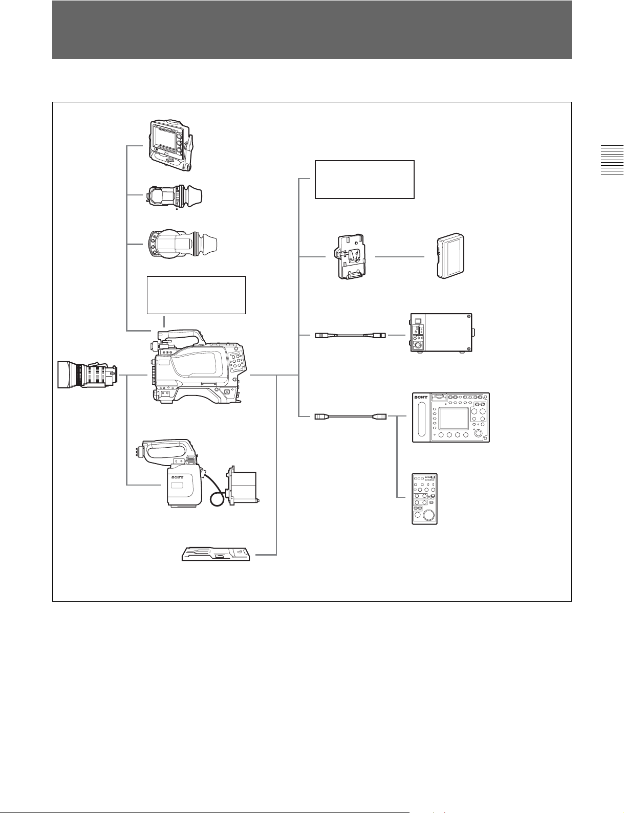
1-2
システム構成
本機の関連機器およびアクセサリーを下図に示します。
エレクトロニック
HD
ビューファインダー
HDVF-C750W
ズームレンズ
HD
ビューファインダー
HDVF-20A
ビューファインダー
回転機構
HD
BKW-401
カラービデオカメラ
HDC-F950
エレクトロニック
エレクトロニック
HD
ビューファインダー
HDVF-C30W
リターンビデオ
セレクター
バッテリーアダプター
CAC-6
BKP-L551
光ファイバーケーブル
FC2-PD50/PD250
ケーブル
CCA-5
バッテリーパック
BP-L60/L80
カメラ
HD
コントロールユニット
HDCU-F950
リモート
コントロール
ユニット
RM-B750
第
1
章
概
要
HD CCD
ブロックアダプター
三脚アタッチメント
VCT-14
HKC-T950
リモート
コントロール
ユニット
RM-B150
第1章 概要
1-3(J)
Page 12

Page 13

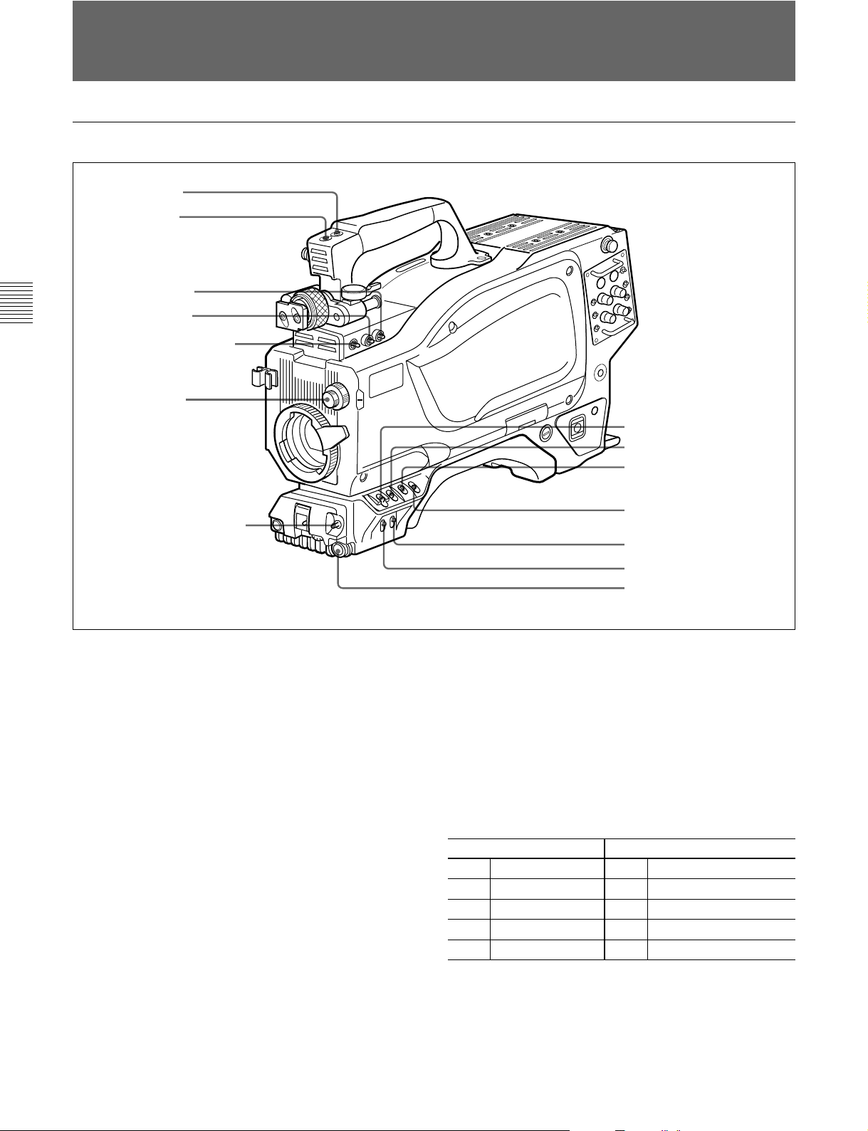
2-1
アクセサリー取り付け部
取っ手
1 ショルダーベルト取り付け金具
2 ビューファインダー前後位置固定レバーと
ロックつまみ
第
2
章
各
部
の
名
称
と
働
き
ショルダーパッド
1
ショルダーベルト取り付け金具
ショルダ ーベルトの一端をこの 取り付け金具に 取り付け、もう一 端を
右側面のショルダーベルト取り付け金具(2-8(J)ページ参照)に取
り付けます。
ビューファインダー前後位置固定レバーとロックつまみ
2
ビューフ ァインダーの位置を前後方向に調整するとき、このレバー
とつまみをゆるめます。
ビューファインダー左右位置固定リング
3
ビュー ファ インダーの位置を左右方向に調整するとき、このリングを
ゆるめます。
レンズ用ケーブルクランプ
4
レンズのケーブルを固定します。
3 ビューファインダー左右位置固定リング
4 レンズ用ケーブルクランプ
5 レンズ固定レバー
6 レンズマウントキャップ
7 レンズマウント
8 三脚マウント
9
レンズマウントキャップ
6
レンズを取り付けて いない とき は、このキャ ッ プをはめ込んでおい
てく ださい。 レンズ固定レバーを押し上げると、取り外せます。
レンズマウント
7
レンズ(別売り)を取り付けます。
三脚マウント
8
本機を三脚に固定するとき、三脚アタッチメ ントVCT-14を取り付け
ます。
9
レンズのケーブルを接続します。この端子を介して、本機からレン
ズの機能をコントロールすることが できます。
(レンズ)端子(12ピン)
LENS
LENS
端子
第
2
章
各
部
の
名
称
と
働
き
5
レンズ固定レバー
レンズ(別 売り)をレンズマウン トに固定します 。
第2章 各部の名称と働き
2-1(J)
Page 14
コントロール部
2-2
2-2
コントロール部
前部(右)
1
INCOM
2
RET 1
3
Y/RGB
4
R/G/B
第
2
章
各
部
の
名
称
と
働
き
5
ASSIGNABLE
6
FILTER
7
AUTO W/B BAL
ボタン
ボタン
スイッチ
スイッチ
つまみ
スイッチ
スイッチ
8
CAMERA/VTR
9
0
qa
qs
qd
qf
スイッチ
GAIN
OUTPUT/AUTO KNEE
スイッチ
WHITE BAL
DISPLAY
CANCEL/STATUS
MENU SEL
ENTER
スイッチ
スイッチ
スイッチ
つまみ
ボタン
スイッチ
/
1
INCOM
押している 間、インターカム 1 のマイ クが ON になり ます。
2
RET 1
押している 間、カメラコ ン トロールユニットからのリターンビデオ 1信
号をビュー ファインダー画面でモニター できます。側面のRET1ボ
タンと同じ機能です。
3
Y/RGB(Y/RGB
VFおよびTESTOUT端子から出力するビデオ信号を選択します。
:Y信号を出力。(電源投入時の初期設定)
Y
RGB
4
R/G/B(赤/緑/
Y/RGBスイッチが RGBに設定されているとき、VFおよびTEST
OUT端子から出力するコンポーネント信号を選 択します。
(インターカム1)ボタン
(リターンビデオ1)ボタン
信号)スイッチ
:R/G/Bスイッチで 選択されたコンポーネ ントビデオ信号を
出力。
青)スイッチ
5
ASSIGNABLE
OPERATIONメニューにより、機能を割り付けることができます。
◆機能の割り付けかたについては、「4-6-8 その他の設定」(4-21(J)
ページ)をご覧ください。
6
FILTER
被写体 を照らしている光源に合わせて 、適切なフィルター を選択し
ます。
フィルター
ND
1素通し Aクロスフィルター
2 1/4ND B 3200K
3 1/8ND C 4300K
4 1/16ND D 6300K
5 1/64ND E 8400K
(内蔵フィルター切り換え)つまみ
(アサイナブル)スイッチ
色温度変換)フィルター
CC(
2-2(J)
第2章 各部の名称と働き
Page 15
7
AUTO W/B BAL
自動調整)スイッチ
ホワイトバランスとブラ ッ クバランス を自動調整します。
:ホワイトバランスを自動調整する。
WHT
:ブラ ッ クバラ ンス を自動調整する。
BLK
(ホワイトバランス/ブラックバランス
1)
qa
WHITE BAL
1)
イッチ
(ホワイトバランスメモリー切り換え)ス
ホワイトバランスの 調整方式、および調整値を記憶するためのメモ
リーを選 択します 。
PRST(
プリセ ッ ト):色温度3200Kに対応するホワイトバランスの
プリセ ッ ト値に調 整される。
8
CAMERA/VTR
スイッチ
本機と接続したVTRへのコントロール信号を切り換えます。設定に
より、VTRによる記録開始の機能が次のように変わります。
機能
VTRCAMERA
OFF
ON SAVE カメラの電源ON。VTRSTARTボタンを押すと、
ON STBY カメラの電源ON。VTRSTARTボタンを押すと、
9
GAIN
SAVE カメラの電源OFF。
数秒後に記録が始まる。
すぐに記録が始まる。
(ゲイン)スイッチ
撮影時の照明の状態により、映像アン プのゲイン(利得)を切り換え
ます。L、M、Hの設定に対応するゲイン値はあらかじめ設定メ
ニューで指定します。出荷時の設定は、L=0dB、M=6dB、H=12dB
です。
◆ ゲイン値の設定について詳しくは、「4-6-4ゲイン切り換え値を設定
する」(4-19(J)ページ)をご覧ください。
なお、OPERATIONメニューのVFDISPLAYページのMESSAGE
設定がONの場合、このスイッチの設定を切り換えると、 新しい 設
定がビューファ インダー画面の設定切り換え/調整経過メッセージ
1)
またはB:メモリ ー Aまたは Bを選択する。 AUTOW/BBALス
A
イッチを WHT側に押すと、そのときの FILTERつまみの設定
に応じてホワイトバランスが自動調整される。調整値は選択さ
れたメモリーに記憶 される。 各メモリ ーに、 4個ずつ合計8個
の調整値を記憶できる。
OPERATIONメニューのVFDISPLAYページのMESSAGE設定
がONの場合、このスイッチの設定を切り換える と 、 新 しい設定が
ビューフ ァインダー画面の設定切り換え/調整経過メッセージ表 示
部に約3秒間表示されます。
1)
(例:「WHITE:Ach」、「WHITE:PRESET」)
qs
DISPLAY
(ディスプレイ)スイッチ
ビューフ ァインダー画面内の表示(セーフティゾーンマ ーカー、セン
ターマーカーおよび文字表示)およびメニュー画面のON/OFFを
行います。
:ビュー ファインダー画面にオペレーシ ョ ン時の状態を示す文
ON
字が現れる。
:ビュ ー ファ インダー画面の文字表示がすべて消える。
OFF
MENU
◆設定メニューと設定のしかたについ ては、「4-6 OPERATIONメ
:ビュ ー ファ インダー画面に設定メニューが表示される。
ニュー によ る セットアップ 」 (4-15(J)ページ)をご覧ください。
表示部に約3秒間表示されます。
(例:「GAIN:12dB」)
qd
CANCEL/STATUS
(取り消し/ステータス)スイッチ
ビューフ ァインダーにメニューが表示されているとき、メニュー設定
0
OUTPUT/AUTO KNEE
1)
イッチ
(出力信号選択/オートニー)ス
の内容を取り消したり、メニューの前画 面に戻る働きをします。メ
ニューが表示されていないときは、!INDの項目を表示します。
本機からVTR、ビュー ファ インダー、ビデオモニタ ーへの出力信号
(カラーバー信号、また はカ メラが撮影している映像)を選びます。
撮影している映像を出力信号として選択しているときは、オート
◆! INDの項目については、「4-6-2!表 示 を点 灯させる項目を選択
する」(4-17(J)ページ)をご覧ください。
ニー機能を使うことが できます。
qf
スイ ッチ設定と出力信号/オートニー機能 の選 択 の関 係は次のとお
りです。
OUTPUT AUTO KNEE
BARS OFF カラーバー信号が出力される。
CAM OFF カメラで撮影している映像が出力される。
CAM ON カメラで撮影している映像が出力される。
..............................................................................................................................................................................................................................................................
1)カメラコントロールユニット接 続時は機能しません。
機能
オートニー回 路は機能しない。
オートニー回 路が機能する。
MENU SEL
タン(ロータリーエンコーダー)
ビューフ ァインダー画面に表示 さ れたメニュー項目を選択(回転)/
確定(押す)します。
(メニュー選択)つまみ
第2章 各部の名称と働き
/ENTER
(確定)ボ
2-3(J)
第
2
章
各
部
の
名
称
と
働
き
Page 16
コントロール部
2-2
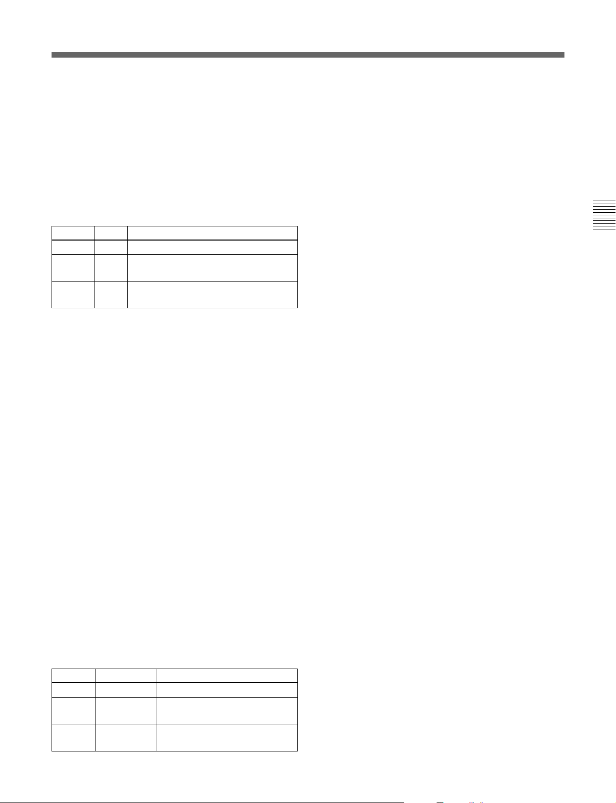
前部(左)
5
端子
VF
第
2
章
各
部
の
名
称
と
働
き
1
TEST OUT
現在は使用しません
2
MIC 1 IN
3
RET 1
4
MIC IN
端子
端子
ボタン
スイッチ
6
SHUTTER
7
INCOM/EAR LEVEL
8
VTR START
スイッチ
つまみ
ボタン
1
TEST OUT
(テスト出力)端子(
BNC
型)
必要に応じてモニター に接続します。
Y/RGBスイッチと R/G/Bスイッチで選択した信号を出力します。
2
MIC 1 IN
(マイク1入力)端子(
XLR型、3
ピン、メス)
マイクを接 続します。
MICINスイッチによって、後面のAUDIOINCH-1端子と切り換
えます。
3
RET 1
(リターンビデオ1)ボタン
押している 間、カメラコ ン トロールユニットからのリターンビデオ 1信
号をビュー フ ァ インダー画面でモニターできます。取っ手上部およ
び右側面のRET1ボタンと同じ機能です。
4
MIC IN
(マイク入力切り換え)スイッチ
MIC1IN端子に接続したマイクと後面のAUDIOINCH-1端子に
接続したマイクのどちら を使用するかを選択します。
+48V/FRONT:
MIC1IN端子に接続したマイクを使用し、 マ
イクに +48Vの電源を供給します。
OFF/FRONT:
MIC1IN端子に接続したマイクを、電 源を供
給しないで使用します。
REAR:
後面のAUDIOINCH-1端子に接続したマイクを使 用
します。マイ クへ電源を供給するかどうかは、後面のAUDIO
INCH-1端子用のマイク電源スイッチで設定できます。
(ビューファインダー)端子(20ピン)
5
VF
ビューフ ァインダーのケーブルを接続し ます。
2-4(J)
第2章 各部の名称と働き
Page 17

6
SHUTTER
電子シャッターは働かない。
OFF:
電子シャッターを使用する。
ON:
スイッチをこの位置にする と、シャ ッ タースピー ドおよび
SEL:
(シャッター)スイッチ
1)
シャ ッターモー ドの設定が切り換わる。
◆詳しくは「 4-2電子シャッターの設定」(4-4(J)ページ)をご覧ください。
7
INCOM/EAR LEVEL
(インターカム/イヤホン音量)つ
まみ
インカムおよびイ ヤホンの音声レベルを調整 し ま す。
インカムレベルの調整は後面(右)パネルのINCOMLEVELス
イッチがF側に設定されているときに有効です。
8
VTR START
(記録開始/停止ボタン)ボタン
VTRを接続しているときは、押すと記録が始まり、もう一度押すと
止まり ます。レンズに付 いているVTRボタンと同じ働き を します。
カメ ラコン トロールユニット接 続時は、OPERATIONメニューにより、
RET2/INCOM1MIC/INCOM2MICのスイッチ機能に変更する
こともできます。
◆詳しくは、「4-6-8その他の設定」(4-21(J)ページ)をご覧ください。
第
2
章
各
部
の
名
称
と
働
き
..............................................................................................................................................................................................................................................................
1)カメラコントロールユニット接 続時は機能しません。
第2章 各部の名称と働き
2-5(J)
Page 18
コントロール部
2-2
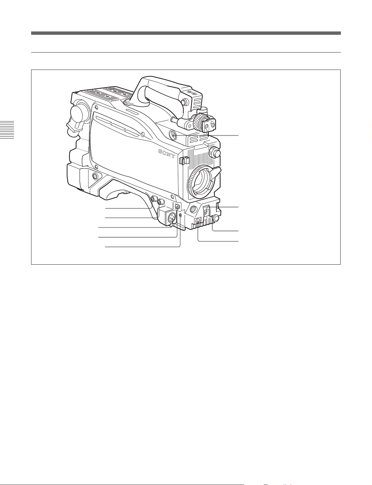
後面(左)
1
タリーランプとタリースイッチ
第
2
章
各
部
の
名
称
と
働
き
2
3
4
端子
CCU
INCOM1、2
EARPHONE
端子
ジャック
8
RET CONT
端子
5
TRACKER
6
GENLOCK IN/RET IN/
PROMPTER OUT
切り換えスイッチ
7
AUDIO IN 1、2端子/
1
タリーランプとタリースイッチ
:外部からのタ リーボタ ンやCALLボタンなどによる呼び出し
ON
端子
端子と
スイッチ
時にタリーランプが点灯する。
:タリーランプを点灯禁止にする。
OFF
2
(カメラコントロールユニット)端子(光マルチコ
CCU
ネクター)
光電気複合ケーブルでカメラコントロールユニットと接続します。
4
INCOM1、2
(インターカム1、2)端子(
XLR型5
ピン)
インターカムの音声信号を入出力します。
4
EARPHONE
(イヤホン)ジャック(ミニジャック)
イヤホ ン、ヘッ ドホ ンなどを接続し、VTRの再生音声信号を出力し
ます。
5
TRACKER
9
EXT I/O
0
REMOTE
qa
DC OUT
qs
DC IN
qd
HD SERIAL RET OUT
qf
HD SERIAL LINK A/LINK B OUT
端子
端子
端子
端子
(トラッカー) 端子(20ピン)
端子
端子
この端子を介して、カメラマン とトラッカーとの通話およびインターカ
ム1、2の送受信ができ ます。 また、 ア ップタリー信 号とプ ログラム
オーディオ信号を 出力します。トランクラインの入出力信号もアサイ
ンされ ています。
6
GENLOCK IN/RET IN/PROMPTER OUT
信号入力
(
BNC
リターン信号入力/プロンプター信号出力)端子
/
型)と切り換えスイッチ
(外部同期
切り換えスイ ッチで端子の機能を選択します。
GENLOCK IN
:外部同期用信号を入力する(スタンドアローン
使用時のみ有効)。
RET IN
:リターン信 号を入力する(スタンドアロー ン使用時のみ
有効)。
PROMPTER OUT
:プロンプタ ー信号を出力する(カメラコ ン
トロールユニット接続時のみ有効)。
2-6(J)
第2章 各部の名称と働き
Page 19
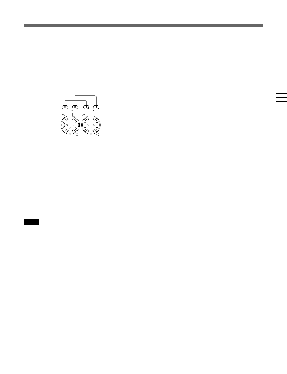
7
AUDIO IN
スイッチ
ン)
/
(オーディオ入力)1、2端子(
XLR型3
ピ
オーディオ信号を入力しま す 。チャ ンネル1、2それぞれに対して入
力選択スイッチ、マイ ク電源スイッチが用意されています。
入力選択スイッチ
マイク電源スイッチ
qs
DC IN(DC
電源入力)端子(
XLR型4
ピン)
ACアダプターAC-550、バッテリーなどを接続し、本機に電源を供
給します。
qd
HD SERIAL RET OUT(HD
BNC
型)
端子(
シリアルリターン出力)
HDSDIのシリアルデータを出力します。カメラコントロールユニッ
トからのリターン信 号を出 力します。
LINE MIC OFF+48V
CH-1
LINE MIC OFF+48V
AUDIO
IN
CH-1
入力選択スイッチ:入力する外部音声信号を選択します。
:ライ ン入力を接続するとき。
LINE
:マイクを接続するとき(マイクのゲイン設定は、メ
MIC
ニューで行います)。
マイク電源スイッチ:マイクを接 続したとき、マイクに電源を供
給するかどうかを設定します。
+48Vの電源をマイクに供 給する。
+48V:
電源をマイクに供給しない。
OFF:
●
:+12Vの電源をマイクに供給する。
ご注意
+12V電源を供給するためにはセットの改造が必要です。
◆詳しくは、インストレーショ ン&メンテナンスマニュアルを参照してくださ
い。また、実際の作業はサービス担当者にご依頼ください。
qf
HD SERIAL LINK A/LINK B OUT (HD
リンクB出力)端子(
ク
A/
BNC
型)
シリアルリン
カメ ラの本線信号をHD-SDI4:4:4(DualLink)として出力しま す。
第
2
章
各
部
の
名
称
と
働
き
8
RET CONT
(リターンコントロール)端子(6ピン)
リターンビデオセレク ター CAC-6を接続します。
9
EXT I/O
(外部入出力)端子(20ピン)
外部にY/Pb/Pr信号などを送り出すための端子です。
0
REMOTE
(リモート)端子(8ピン)
リモー トコントロールユニットRM-B150/B750、リモー トコントロール
パネルRCP-700シリーズ、またはマスターセットアップユニット
MSU-700A/750を接続します。
qa
DC OUT(DC
電源出力)端子(4ピン)
別売りのワイヤレスレシーバーなどに電源を供給します。
第2章 各部の名称と働き
2-7(J)
Page 20
コントロール部
2-2
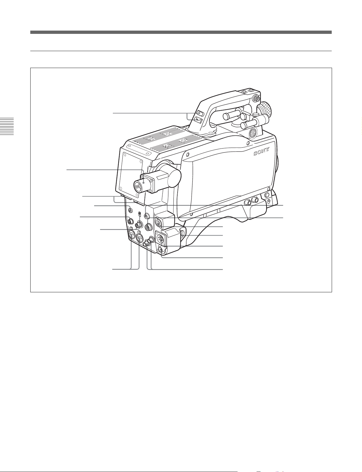
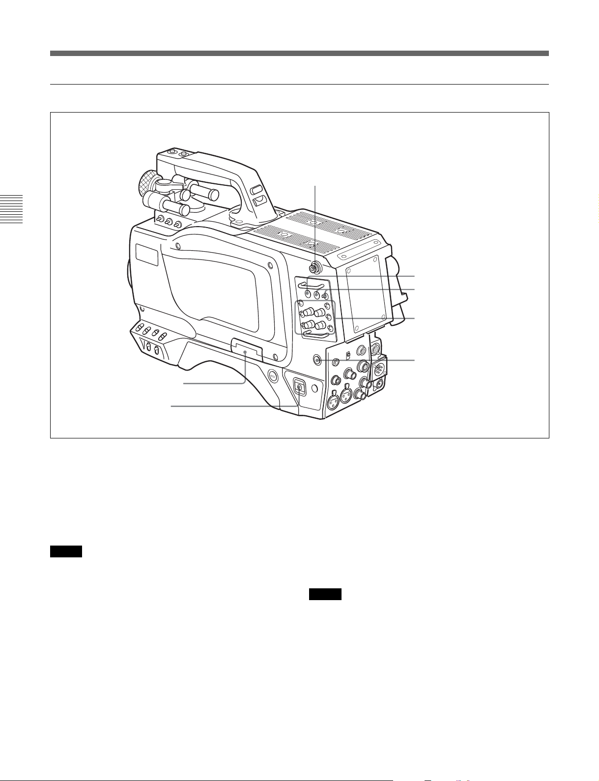
後面(右)
ショルダーベルト取り付け金具
第
2
章
各
部
の
名
称
と
働
き
1
メモリースティック部
2
POWER
1
メモリースティック部
蓋の中に、メモリースティックを挿入するスロットと、 取り出すときに
押すイジェクトボタンがあります。
スイッチ
3
RET 1
(リターンビデオ1)ボタン
押している 間、カメラコ ン トロールユニットからのリターンビデオ 1信
号をビュー ファインダー画面でモニターできます。
ページ参照)
(2-1(J)
3
RET1
4
ボタン/スイッチ
RET
5
INCOM1、2
6
CALL
ボタン
つまみ/スイッチ
ボタン
スロッ トに挿 入したメ モリ ー ス ティックに データを書き込んだり、メモ
リースティックからデータを読 み 出し ているときはイジェ クトボタン が
赤く 点灯します。
ご注意
イジェクトボタンが点灯しているときはメモリー スティックを抜き差し
4
リターンビデオ1と並 行して別 の系統のシステムを使用している場
合、スイ ッチで選択した信号(リターンビデオ 2、 3、4)を、ボタ ンを押
している間ビューファインダー画面でモニターでき ます。
(リターンビデオ)ボタン/スイッチ
RET
しないでください。
ご注意
◆メモリースティックの 操 作については、システムマニュアルおよび
「4-6-9オペレーターファイルを操作する」(4-22(J)ページ)を参照 して
ください。
RET1 ボタンとRETボタンを両方とも押した場合は、RET1ボタン
が優先されます。
2
POWER
CCU
EXT
2-8(J)
(電源)スイッチ
:カメラ コン トロールユニットからの給電で電源が入ります。
:DC INまたはVTR端子からの給電で電源が入ります。
第2章 各部の名称と働き
5
INCOM1、2
(インターカム1、2)つまみ/スイッチ
インターカムライ ン1、2それぞれに対し、PGM調整つまみ /スイッ
チ、ラ イン選択ス イッチ、 LEVEL/TALKスイッチ、およびINCOM
調整つまみが用意されています。
Page 21
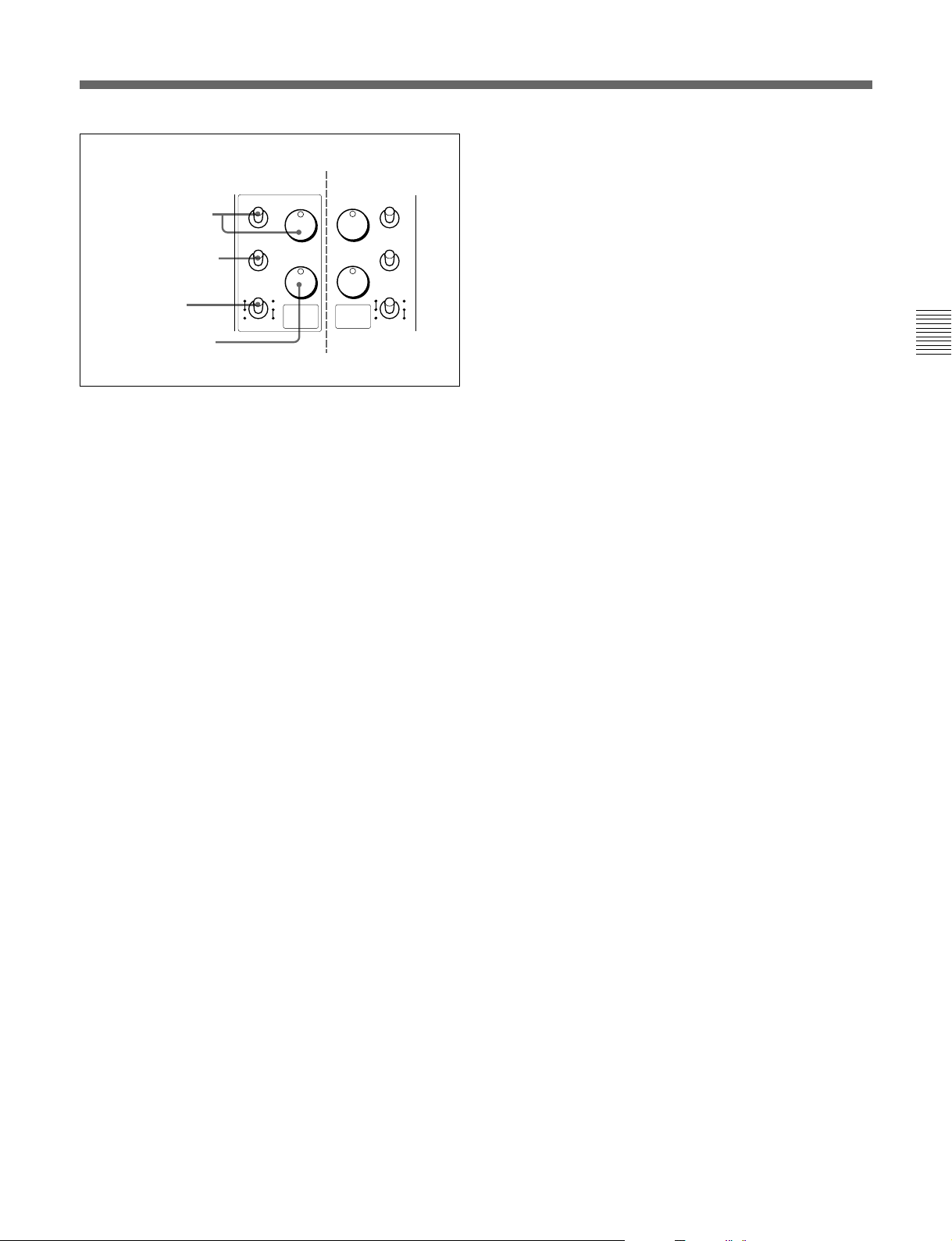
INCOM2
PGM
PROD
ENG
TALK
R
FONOFF
1
2
INCOM
側
PGM
1
INCOM
構成は1側と同じ
(
PGM
INCOM
INCOM
INCOM1
調整つまみ
PGM
スイッチ
ライン選択スイッチ
/
LEVEL
LEVEL/TALK
スイッチ
INCOM
PGM
調整つまみ
(プログラ ム) 調整つまみ/スイ ッチ:プログラム音声の受
側
PGM
1
2
PROD
ENG
LEVEL
TALK
R
2
FONOFF
信レベルを調整します。それぞれ対応するスイッチで、プログ
ラム 1 か 2を選択できます。
ライン選択スイッチ:インターカムライ ンを選択します。
:プロデューサーラ インを使用するとき。
PROD
:エンジニアラインを使用するとき。
ENG
LEVEL/TALK
R/ON
(レベル/トーク)ス イッチ:
:インターカム用 ヘッ ドセ ットのマイクを O N にします。
インターカム音声の受信レベルはINCOM調整つまみで
調整します。
:インターカム用ヘッ ドセ ットのマイクをOFFにします。
R/OFF
インターカム音声の受信レベルはINCOM調整つまみで
調整します。
:インターカム用 ヘッ ドセ ットのマイクをOFFにします。
F/OFF
インタ ーカ ム 音声の受信レベルは、カメラ前面の
INCOM/EARLEVELつまみで調整できます。
INCOM
(インターカム) 調整つまみ:インターカム音声の受信レ
ベルを調整します。
)
第
2
章
各
部
の
名
称
と
働
き
6
(コール)ボタン
CALL
押すと、RCP-700シリーズ(リモートコントロールパネル)やMSU700A/750(マスター セットアップユニット)レッ ドタ リーランプ が点灯
します。RCPやMSUオペレーターを呼び出すときに使います。
第2章 各部の名称と働き
2-9(J)
Page 22

Page 23

3-1
強い衝撃を与えない
内部構造や外観の変形などの損傷を受けることがあります。
使い終わったら
電源スイッチを切ってく ださい。
使用、保管場所
水平な場所、空調のある場所に保管してください。
次のような場所での使用および保管は避けてください。
• 極端に暑い所や寒い所
• 湿気の多い所
• 激しく振動する所
• 強い磁気を発生する所
• 直射日光が長時間あたる所や暖房器具の近く
使用上のご注意
第
3
章
準
備
第
3
章
準
備
第3章 準備
3-1(J)
Page 24
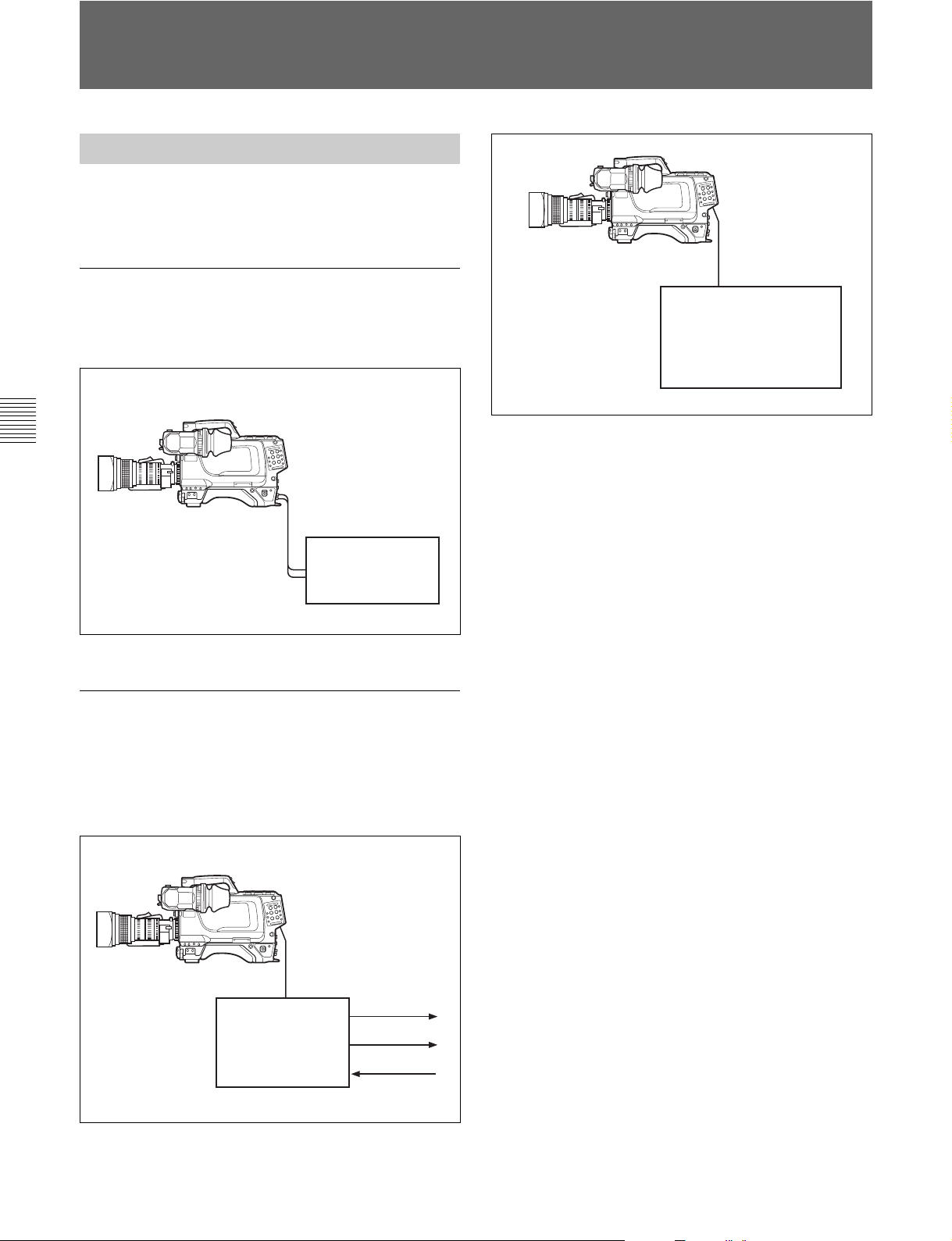
3-2
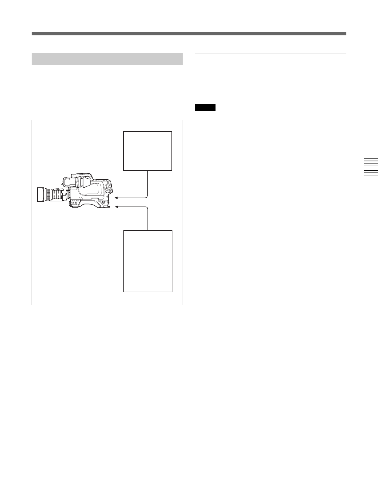
接続と電源
の接続
HDC-F950
接続
BNC
ケーブル
HD SERIAL
LINK A / LINK B OUT
4:4:4対応 HD VTR
接続ケーブル
HDC-F950
• リモートコントロール
• リモートコントロール
リモートコントロールパネル/ユニットを接続する
リモートコントロールで使用可能な機能
カメ ラコントロールユニットを接続して リモートコントロールパネルや
リモー トコン トロールユニットから操作する場合、リモー トコン トロール
でも本機のメニュー操作と同様に、以下の機能が働きます。
• オートーセットアップ (レ ベ ル 調 整、 オートブラック/ホワイ トレベル調
整)
• シー ンファ イ ル、セッ トアップファイル データのクリア
• ペインテ ィングデータのクリア
• テスト信号の出力
ユニット
パネル
CCA-5
RM-B750/B150
RCP-700
シリーズ
3-2-1
本機には、VTR、カメラコントロー ルユニット、またはリモ ートコント
ロールパネルを接続することができ ます。
VTR
本機に取り付けたカメラアダプターに、下図のようにVTRを接続す
ることができます。
第
3
章
準
備
カメラアダプターとカメラコントロールユニッ
ト
リモートコントロールパネルの接続
/
HDカメラコントロールユニットHDCU-F950やRCP-700シリーズの
リモー トコントロールパネル、または RM-B750などのリモートコント
ロールユニットを接続することができ ます。
光ファイバーケーブル
HDC-F950
カメラコントロール
ユニット
HDCU-F950
カメラコントロールユニットを接続する
FC2-PD50/PD250
マイク出力
映像出力
電源入力
カラーバーまたはテスト信号の出力について
リモートコン トロールパネルやリモートコン トロールユニットからオート
セッ トアップ を実行する場合は、カラーバ ーまたはテス ト信号を出 力
している 状態でもセットアップが可能です。セットアップ終了後は、
再びカラ ーバーま たはテスト信号 がビューファインダー画面に表示さ
れます。
◆詳しくはシステムマニュアルを ご覧ください。
3-2(J)
第3章 準備
Page 25
3-2-2
電源の供給
バッテリーパックを使う
本機は次のいずれかの電源を使用します。
• 接続された機器の電源
• ACアダプタ ーを介して接続された電源
• 装着されたバッテリー電源
カメラコントロール
ユニット
HDCU-F950
光マルチ
コネクター
カラービデオカメラ
HD
HDC-F950
DC IN
端子
•ACアダプター
• バッテリーアダプ
AC-550
ター
BKP-L551
+バッテリーパッ
ク
BP-L60/L80
バッテ リーパ ック を使って電源を供給する場合は、POWERスイッチ
をEXTにして、本機にバッテリーアダプター またはバッ テ リ ーケース
を取 り付けます。
ご注意
バッテリーケースDC-L1/L90は直接本機に取り付けることはできま
せん。
バッテリーパック
BP-L60/L80
を使うには
別売りのバッテリーアダプターBKP-L551を使います。
◆詳しくは、インストレーション&メンテナンスマニュアルをご覧ください。
第
3
章
準
備
POWERスイッチをCCUに設定すると、カメラコントロールユニッ
トが接続されているときに電源が入ります。また、EXTに設定する
と、 DCIN端子から給電されているときに電源が入ります。
第3章 準備
3-3(J)
Page 26
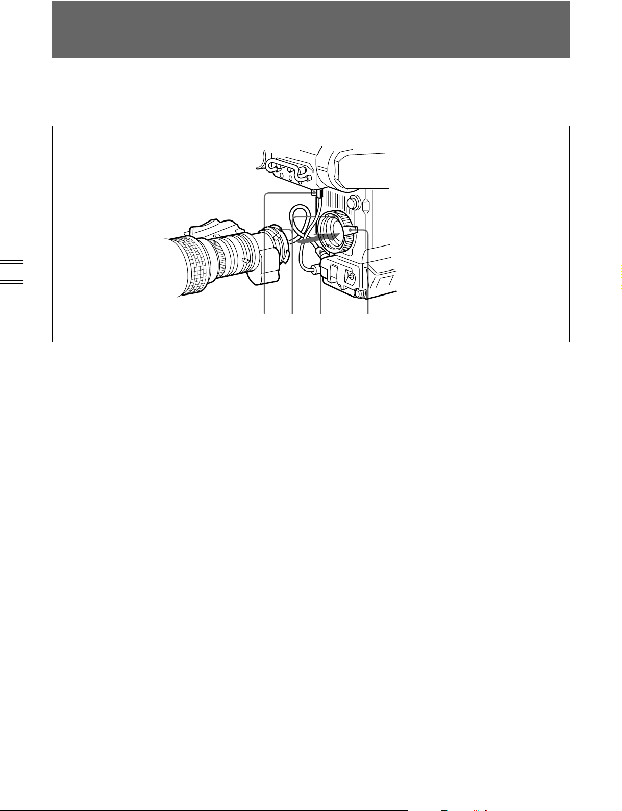
3-3
レンズの取り付け
本機に取り付ける手順は、次のとおりです。
第
3
章
準
備
1 レンズ固定レバーを押し上げて、レンズマウン トからレンズ マウ
ントキャップを外す。
◆レンズの取り扱いについては、レンズに付属の取 扱説明書をご覧くださ
い。
1,3425
4 レンズケーブルを LENS端子に接続する。
5 レンズケーブルをケーブルク ラ ンプに押し込む。
2 レンズマウン ト上部中央の凹部にレンズの位置決 めピ ンを 合わ
せ、レンズをマウン トに 差し込む。
3 レンズを支えながら、レンズ固定レバーを押し下げ てレンズを
固定する。
3-4(J)
第3章 準備
Page 27
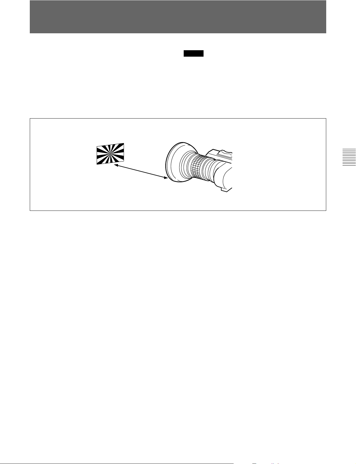
3-4
フランジバックの調整
次のような場合、フランジバッ ク1)の調整が必要です。
•レンズを初めて取り付けたとき
•レンズを交換したとき
• ズーム操作の際に、望遠・広角の両方で焦点がきちんと合わな
いと き
フランジバックの調整の手順は、次のとおりです。
約
3m
ご注意
フランジバックの 調整 のために 操作する レンズの各部分の位置は、
レンズによって 異なります。レンズに付 属の取扱説明書で確認して
ください。
第
3
章
準
備
1 絞りのモー ドを手動にして、絞り を開放に する。
2 フランジ バック調整用チャートを本機か ら3mぐらいの所に置
き、適正な映 像出 力レベルが得られるように、照明を調整す
る。
2)
3 Ff
リング固定ネジをゆるめる。
4 手動または電動で、ズームリングを望遠位置にする。
5 フランジ バック調 整用チャー トを写し 、フォーカスリングを回して
焦点を合わせる。
6 ズームリングを広角位置にする。
7 Ffリングを回 し、フランジバック調 整用チャートに 焦 点 を合わ せ
る。このと き、距離リングを動かさ ないよ う に注意して く ださ い。
8 遠望と広角の両方で焦点が合うようになるまで、手順4〜7の
操作を繰り返す。
9 Ffリング固定ネジをしっかり締める。
.............................................................................................................................................................................................................................................................
フランジバック
1)
レンズマウン トの取り付け面から結像 面までの距離
2) Ff
Flangefocallength
第3章 準備
3-5(J)
Page 28
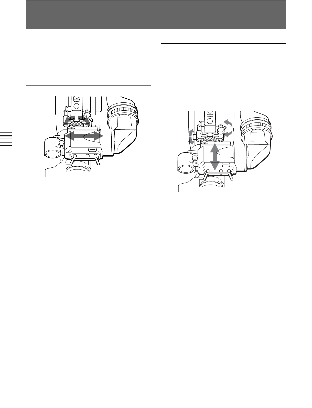
3-5
ビューファインダーの位置調整
ビュー ファ インダーの位置を左右方向および前後方向に調整して、
ビューフ ァインダー内を見やすくすることができます。
左右方向の調整
3
1
本機をキャリングケースに収納するときは
ビューフ ァインダーをマイ ク側いっぱいに寄せ、ビュー ファ インダー
左右位置固定リングを締めた状態で収納します。
前後方向の調整
1
1
3
2
第
3
章
準
備
3
2
1 ビュー ファインダー左右位置固定リングをゆるめる。
2 ビュー ファ インダーを左右にス ライドさせ、 内部が見やすい位置
に調整する。
3 ビュー ファインダー左右位置固定リングを締める 。
1 ビュー ファ インダー前後位置固定レ バ ーとロックつまみをゆるめ
る。
2 ビュー ファ インダーを前後にス ライドさせ、 内部が見やすい位置
に調整する。
3 ビュー ファインダー前後位置固定リングとロックつまみを締め
る。
3-6(J)
第3章 準備
Page 29
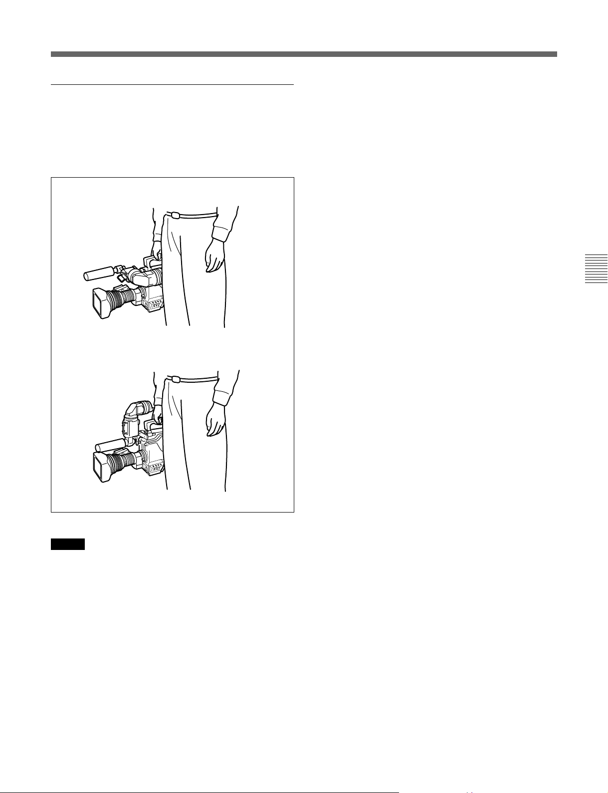
ビューファインダーが脚に当たらないようにする
には
本機 を持ち運ぶときに、ビュー ファ インダーが脚に当たらないよ う に
するには、ビューフ ァインダー回転機構BKW-401(別売り)を取り付
けて、ビュー ファインダーを上部に回転させてお きます。
m
第
3
章
準
備
ご注意
ビューフ ァインダーを上部に回転させる前に、ビュー ファ インダーを
少し前に引き出した位置で固定してください。ビューフ ァインダーの
前後方向の位置が最後部になっていると、ビュ ー ファ インダー回転
機構のアームが本機の取っ手に当たります。
第3章 準備
3-7(J)
Page 30
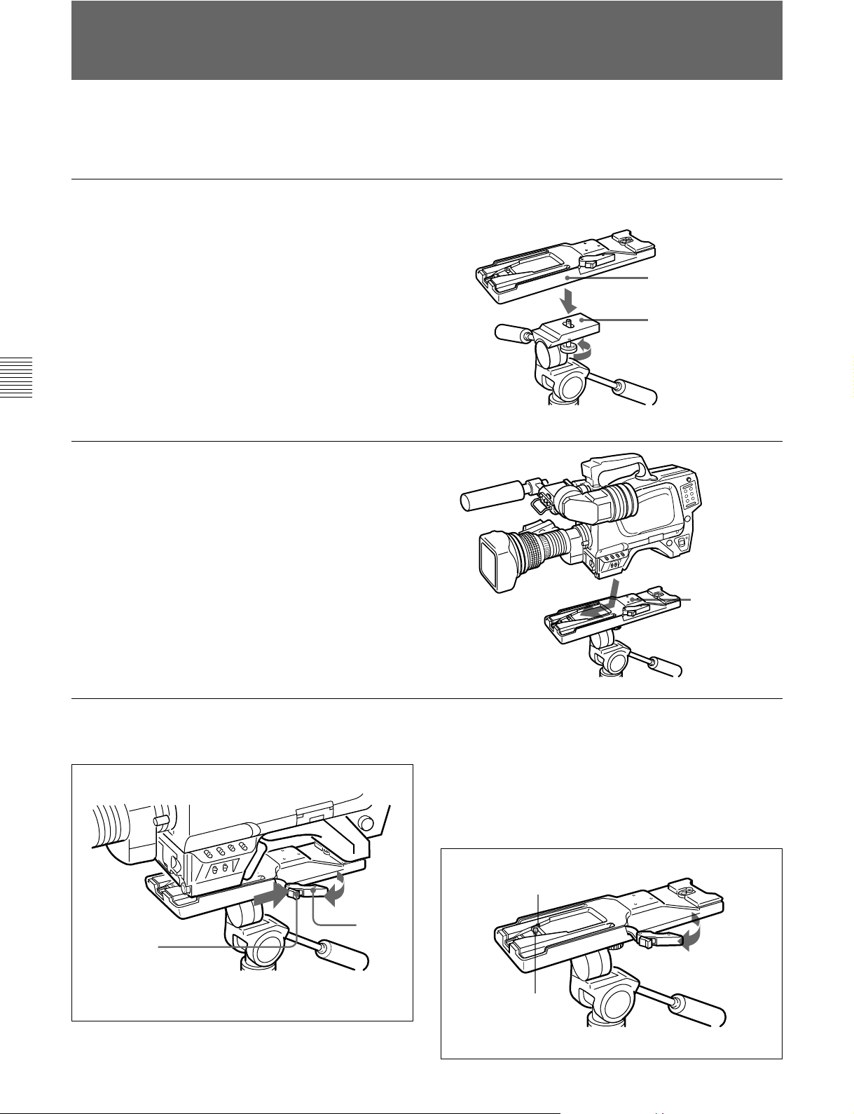
3-6
別売りの三脚アタッチメ ントVCT-14を使って本機を三脚に取り付け
るには、次のようにします。
三脚への取り付け
1 三脚アタッチメ ントを三脚に取 り付け る。
三脚アタッチメ ントの底 部にある穴 のうち、 本機と三脚アタッチ
メントの重 心を考慮して、適切な位置の 穴を選びます。選んだ
穴の径が、雲台のカメラ取り付けネ ジの径と合 うことを 確認し
ます。
三脚
アタッチメント
雲台
第
3
章
準
備
2 本機を三脚アタッチメントに 取り付ける。
アタ ッチメ ン トの溝に沿って、カチッ と音がするまで、本機を前
方にすべ ら せ ます。
三脚
三脚
アタッチメント
三脚アタッチメントから取り外すには
赤いボタン を押しながら、レバーを矢印の方向へ動かします。
ピンが元の位置に戻らない場合
本機を取り外した後、三脚アタッチメ ントのピンが元の位置(ピン収
納部)に戻らない場合は、もう一 度 、赤 い ボタンを 押しな がら、レ
バー を矢印の方向へ動かして、ピンをも との位置に戻します。ピン
が出たままでは、本機の取り付けができません。
赤いボタン
3-8(J)
ピン収納部
レバー
ピン
第3章 準備
Page 31

3-7
ショルダーベルトの取り付け
本機 を肩か ら下げて使用する場合は、別売りの ショルダーベルトを
ショル ダーベルト取り付 け金 具に取り付けます。
ショルダーベルト
取り付け金具
取り付けるには
クリップ
ベルトを上に引っ張って
きちんと固定する。
f
第
3
章
準
備
取り外すには
ここを押しながら
矢印の方向に引く。
f
第3章 準備
3-9(J)
Page 32

Page 33

4-1
本機を使用し、常に高画質の映像を得るためには、状況に応じた
ブラ ッ クバラ ンス と ホワイトバランスの調整が必要です。
ブラックバランスの調整
次のような場合に調整が必要です。
• 本機を初めて使用するとき
• 長時間使用しなかった後に使用するとき
• 周囲の温度が大幅に変化した状況で使用するとき
• 設定メニューでゲイン切り換え値を変更したとき
通常は、電源を再び入れた場合でも調整し直す必要はありませ
ん。
ブラックバランス/ホワイトバランスの調整
ブラックバランス調整の手順
1 図のようにスイッチを設定する。
OUTPUT/AUTO KNEE:CAM
第
4
章
記
録
の
た
め
の
調
整
と
設
定
ホワイトバランスの調整
照明条件が変わったときには、必ず調整し直してください。
ビューファインダー画面の表示について
ブラ ッ クバランス とホ ワイトバランスの調 整を始 めると、ビューファイ
ンダー画面に、調整経過や結果をしらせるメ ッセージが表示され
ます。
ご注意
本機で自動調整される調整値や各設定値は、本機のメモリーに
記憶され、電源を切っても保持されています。
4-1-1
ブラ ッ クバランスの自動調整は、ブラ ッ クセ ット、 ブラ ッ クバラ ンスの
順に実行 されます。
また、ブラ ッ クシェ ーディングを調整することもできます。
ブラ ッ クバラ ンス は、設定メニューの操作によって手動調整するこ
ともできます。
ブラックバランスを調整する
DISPLAY:OFF
:できるだけ小さい
GAIN
ゲイン値を選択する。
2 AUTOW/BBALスイッチをBLK側に押して、指を放す。
AUTO W/B BAL
スイ ッチは中央に戻り、調整が実行されます。
調整中、ビュ ーフ ァインダー画面上に図のよう なメ ッセージが
表示されます。
スイッチ
第
4
章
記
録
の
た
め
の
調
整
と
設
定
◆ブラックバランスの手動調整については、インストレーション&メンテナ
ンスマニュアルをご覧く ださい。
ABB:OP
数秒で調整が終了し、「ABB:OK」のメッセージが 表示されま
す。調整値は自動的にメモリーに記憶されます。
第4章 記録のための調整と設定
4-1(J)
Page 34

ブラックバランス/ホワイトバランスの調整
4-1
ご注意
• ブラ ッ クバラ ンス調整中、絞りは自動的に遮光状態になりま
す。
• ブラ ッ クバラ ンス調整中、ゲイン切り換え回路が自動的に切り
換わり、また、ビューファイ ンダー画面上にフリッカーが数回現
れますが、故障ではありません。
GAINおよびWHITE BALスイッチの設定を変更すると、
ビューファインダー画面の設定変更/調整経過メッセージ表
示部に、設定した位置を知らせるメッセージが約3秒間表示さ
れます(OPERATIONメニューのVF DISPLAYページで
MESSAGE設定がONのとき)。
2 照明条件に合わせて、FILTERつまみの設定を切り換える。
ブラックバランスの自動調整ができないとき
フィルター 色温度変換フィルター
ブラックバランスの調整が正常に終了しなかったときは、ビュー
ファインダー画面に約3秒間エラーメ ッセージ「ABB:NG」が表示さ
れます。
エラーメッセージが 表示されたら、再度ブラックバランスの調整を
試みてください。
繰り返し調整を試みてもエラーメッセージが 表示されると きは、内
部点検をする必要があります 。
◆ 内部点検については、インストレーシ ョン&メンテナンスマニュ アル を ご
覧く ださい。
第
4
章
記
録
の
た
め
の
調
整
と
設
定
ブラックバランスのメモリーについて
メモリ ーに記憶された値は、本機の電源を切った状態でも保存さ
れます。
4-1-2
以下の手順でホワイトバランスを自動調整します。
ホワイトバランスを調整する
ND
1 素通し A クロスフィルター
2 1/4ND B 3200K
3 1/8ND C 4300K
4 1/16ND D 6300K
5 1/64ND E 8400K
FILTERつまみの設定を変更すると、ビューフ ァインダー画面
の設定変更/調整経過メッセージ表 示部に、 設定した位置を
知らせるメ ッセージが約3秒間表示されます(OPERATIONメ
ニューのVF DISPLAYページのMESSAGE設 定がONのと
き)。
3 被写体の照明光源と同じ条件のところにホワイトパターンを
置き、ズームア ップして画面に白を映す。
被写体の近くの白いもの(白布、白壁)で代用することもでき
ます。
最小限必要な白の面積は、図のとおりです。
1 図のようにスイッチを調整する。
FILTER
OUTPUT/AUTO KNEE:CAM
WHITE BAL:A
DISPLAY:OFF
GAIN:
ゲイン値に設定する。
4-2(J)
第4章 記録のための調整と設定
つまみ
または
B
できるだけ小さい
画面センターを中心と
する長方形。
各辺の長さは、画面の
高さ、または幅の
この長方形内に、画面
面積の
10%
積の白が必要。
ご注意
長方形内に高輝度スポットを入れないようにしてください。
4 レンズの絞りを調整する。
手動調整レンズの場合
自動絞り調整機能付きレンズの場合
手動切り換えスイッチを自 動に設定する。
絞り を適正値に合わせる。
:
レンズ側の絞り自動/
:
70%
以上の面
。
Page 35

5 AUTO W/B BALスイッチをWH T側に押して、指を離す。
AUTO W/B BAL
スイッチ
ホワイトバランスの自動調整ができないとき
ホワイトバランスの 調整が正 常に終了しなかったときは、ビュー
ファインダー画面に約3秒間エラーメッセージ「AWB:NG」が表示さ
れます。
エラーメッセー ジが表示された ら、再度ホワイトバランスの調整を
試みてください。
繰り返し調整を試みてもエラーメッセージが 表示されると きは、内
部点検をする必要があります 。
スイ ッチは中央に戻り、ホワイトバランスの自 動 調整が実行さ
れます。
調整中、ビューファインダー画面の左下に「AWB:OP」のメッ
セージが表示さ れます。
約1秒で、図のようなメッセージが表示され、調整が完了しま
す。調整値は、手順
で選択したメモリー(AまたはB)に自動
1
的に記憶 されます。
AWB:OK
ご注意
自動絞り機能付きズームレ ンズを使用した場合、絞りがハンチン
1)
を起こすこと が ありま す 。レンズに 付いている絞りのゲインつま
グ
み(IG、IS、Sなどと表示 されている)を調整してく ださい。
◆内部点検については、別売りのメンテナンスマニュアルをご 覧く ださ
い。
ホワイトバランスを調整する時間がないときは
WHITE BALスイッチをPRSTにします。FILTERつまみの設定位
置に従って、ホワイトバランスが自動的にとれます。
ホワイトバランスのメモリーについて
メモリ ーに記憶された値は、本機の電源を切っても保存されます。
ホワイトバランスのメモ リ ーは、A、Bの2系統があり、AUTO W/B
BALスイッチをWHT側に押すと、そのときの FILTERつまみの設
定に応じてホ ワ イトバランスが自動調整されます。調整値は選択さ
れたメモリーに記憶され ます。各メモリーに、5個ずつ合計10個の
調整値を記憶できます 。A、B各系 統のメモリーの数は、
MAINTENANCEメニューで、それぞれ1個に限定することもでき
ます。この場合、メモリ ーの内容はフィ ルターに連動しません。
◆ MAINTENANCEメニューでの設定については、インストレーシ ョン&メ
ンテナンス マニュアルを ご覧 ください。
第
4
章
記
録
の
た
め
の
調
整
と
設
定
◆詳しくは、レンズの取扱説明書をご覧ください。
............................................................................................................................................................................................................................................................
ハンチング
1)
オートアイリスの応答を繰り返し、映像が暗くなったり明るく
なったりすること。
第4章 記録のための調整と設定
4-3(J)
Page 36

4-2
電子シャッターの設定
ここでは 、 本機の電子シャッターで使用できるシャッターモードに
ついて説明し、シャ ッ ターモー ドとシャッタースピードの設定手順を
示します。
4-2-1
本機の電子シャッターで使用できるシャッターモードと、 選択でき
るシャッタースピードは次のとおりです。
シャッター
モード
標準 1/32、1/48、1/96、
ECS
(拡張クリア
スキャン)
第
4
章
記
録
の
た
め
の
調
整
と
設
定
1)表の数値は、24PsF、23.98PsF時のものです。他のフォーマットで
は設定できる値が異なります。他のフォーマットで設定できる値
については、4-27(J)ページをご覧ください。
ご注意
• どのモードで 電子シャッターを使用しても、シャ ッタースピー ド
が速くなるにつれ、絞りが開き、被写体深度も浅くなります。
• 人工照明、特に蛍光灯や水銀灯などは、輝度が一定のように見
えても、電源周波数に同期して、R、G、B各色の 強さが変化して
います(これをフリッカーと言います)。このような照明下で
シャ ッターを使用すると、フリッカーが より目 立つ場合がありま
す。特に、電源周波数が60Hzの地域では、カラーフリ ッ カーとな
ります。なお、50Hzの地域では、シャ ッタースピー ドを
定すると、フリッカーを低減することができます。
シャッターモードについて
設定できるシャッターモードとシャッタースピード
シャッタースピード
1/125、1/250、1/500、
1/1000(秒)
24.0Hz〜2200Hzの範
囲で連続可変
1)
動きの早い被写体を鮮明に
撮影したい場合
モニター画面を、水平方向
の縞模様が出ないように撮
影したい場合
用途
1
/100に設
4-2-2
シャ ッターモー ドおよび標準モードでのシャッ タ ースピードは
SHUTTERスイッチを切り換えて設定 します。
シャッターモードおよび標準モードでのシャッ
タースピードを設定するには
1 「4-5-1表示項目を選択する」(4-11(J)ページ)の手順を使用
2 SHUTTERスイッチを、ONの位置からSEL側に押す。
3 手順2の表示が消える前 に、もう1度SHUTTERスイッチをSEL
シャッターモード/スピードを選
択する
して、OPERATIONメニューのVFDISPLAYページで
SHUTTERをONに設定する。
SHUTTER
ビューファインダー画面の設定変更/調整経過メッセージ表
示部に、シャ ッターの現在の設定が約3秒間表示されます。
例:「Shutter:1/250」
側に押す。希望のモードまたはスピー ドが表示されるまで、こ
の操作を繰り返す。
すべてのモードとスピー ドが表示される場合は、次のような順
序で表示が切り換わります。
スイッチ
4-4(J)
第4章 記録のための調整と設定
24PsF/23.98PsF時
例
:
標準モード
1/32
1/48
1/96
ECS
出荷時には、左の表にあるすべてのモードとスピードが表示
されるよ うに設定されていますが、あらかじめ必 要なシ ャッ
ターモー ドとスピー ドだけを設定しておくこともできます 。
◆詳しくは、インストレーション&メ ン テナンスマニュ アルをご覧 くださ
い。
1/2501/125
モード
1/500
1/1000
Page 37

モードを選択したときは
ECS
本機前面のMENUSELつまみ/ENTERボタンを回転させてス
ピードを変更することができます。
1度選択したシャッタースピードは、本機の電源を切った状態でも
保持されます。
第
4
章
記
録
の
た
め
の
調
整
と
設
定
第4章 記録のための調整と設定
4-5(J)
Page 38

4-3
ビューファインダー画面上の設定メニュー表示
DISPLAYスイッチをMENUに設定すると、ビューフ ァインダー画面
上にOPERATIONメニューが表示されます。
OPERATIONメニューはページ単位で表示されます。
OPERATIONメニューは、各種設定値の選択や、ビュー ファ イン
ダー画面上に表示させる項目とその表示方法の選択に使用しま
す。
メニューについて
TOP
メニュー項目の全体構成を示す画面としてTOPメニュー画面が
あります。
メニュー画面
TOP
< TOP MENU >
c
USERS
USER MENU CUSTOMIZE
OPERATION
PAINT
MAINTENANCE
FILE
DIAGNOSIS
第
4
章
記
録
の
た
め
の
調
整
と
設
定
ご注意
内部SG基板のスイッチ設定により 、TOPメニューの内容は異なり
ます。
◆詳しくは、インストレーシ ョン&メンテナン ス マニュアルを ご覧 ください。
メニュー画面を表示させるには
TOP
STATUS/CANCELスイッチをSTATUS側に倒しながらDISPLAY
スイ ッチをOFFからMENUに切り換えます。
TOPメニューには、次のようなサブメニューがあります。
メニュー
USER
USERメニューは、ユーザーがメ ニューの中からよ く使用する項目
を選択 して入れておきます。最大60ページまで追加可能です。項
目、ページの追加、削除はUSERMENU CUSTOMIZEメニュー
で行ないます。
USER MENU CUSTOMIZE
USERメニューに必要なページや 項目を追加、削除するときに使
用します。
◆詳しくは「4-5USERメニューの使いかた」(4-11(J)ページ)をご覧く ださ
い。
OPERATION
通常カメラマンが本機を運用するときに必要なVF内のマーカー
や文字表示などの設定を変更する項目が含まれています。
通常、DISPLAYスイッチをMENUに切り換えると、このメ ニューが
表示されます。
◆このメニューで行う調 整 や セットアップに つ いて 詳しくは、「 4-6
OPERATIONメニューによるセットアップ 」(4-15(J)ページ)をご覧く だ
さい。
PAINT
波形モニター等を使用してカメラの出力の波形を監視しながら、
細かな画像調整をするための設定項目が含まれています。通常、
各項目の設定を行うにはビデオエンジニアのサポートが必要で
す。
項目の設定は、外部のリモートコントロールパネルやマスターセッ ト
アップユニットなどでも行えます が、 このメニュー自体は、本機を
屋外で単体で使用する場合に有効です。MSU-700A/750の
PAINTメニューとほぼ同等です。
メニュー
メニュー
メニュー
4-6(J)
DISPLAY
スイッチ
STATUS/CANCEL
MENU SEL
第4章 記録のための調整と設定
つまみ
スイッチ
/ENTER
ボタン
◆このメニュ ーで行う設定項目について は、「4-7PAINTメニュー」
(4-23(J)ページ)をご覧く ださい。
MAINTENANCE
使用頻度の低い設定項目が含まれています。MSU-700A/750の
MAINTENANCEメニューとほぼ同等です。
メニュー
FILE
リファレンスファイル、 OHBファイル、レンズファイ ル、オペレーター
プリセ ッ トファイルの 書き込 み およ びクリアなど のファイル操作を行
います。
メニュー
Page 39

DIAGNOSIS
自己診断情報を表示します。
メニューに戻るには
TOP
次の2とおりの方法があります。
• メニュー画面の各ページの右上に表示されているTOPに→
マーク を合わせ、MENU SELつまみ/ENTERボタンを押す。
• STATUS/CANCELスイッチをCANCEL側に2度押す。
TOPメニュー画面に戻ります。
◆これらのメニューについて詳しくは、インストレーシ ョン&メンテナンスマ
ニュアルおよびシス テムマニュ アルを ご覧ください。
メニュー
3 MENUSELつまみ/ENTERボタンを押す。
選択したページの各項目の設定内容が表示され、現在の選
択項目に→マークが付きます。
<VF DISPLAY>
EX : ON BATT : OFF
ZOOM : OFF RETURN: ON
FOCUS : OFF
ND : ON
CC : ON
IRIS : ON MESSAG: ALL
WHITE : OFF
D5600K: ON
GAIN : ON
SHUTT : ON
c
1
4-3-1
設定メニューの基本操作
DISPLAY
STATUS/CANCEL
MENU SEL
スイッチ
つまみ
/ENTER
スイッチ
1 DISPLAYスイッチをOFFからMENUに切り換える。
OPERATIONメニュー画面が表示されます。
ページ番号
<VF DISPLAY> ?
EX : ON BATT : OFF
ZOOM : OFF RETURN: ON
FOCUS : OFF
ND : ON
CC : ON
IRIS : ON MESSAG: ALL
WHITE : OFF
D5600K: ON
GAIN : ON
SHUTT : ON
1
ボタン
4 MENU SELつまみ/ENTERボタンを回して、→マークを設
定したい項目に移動する。
5 MENU SELつまみ/ENTERボタンを押す。
→マーク が?マークに変わり、点滅します。
6 MENU SELつまみ/ENTERボタンを回して、設定値を変更
する。
速く 回すと数値が速く変化し、ゆっくり回すと微調整ができま
す。
変更した数値を取り消すには
MENU SELつまみ/ENTERボタンを押す前に、STATUS/
CANCELスイッチをCANCEL側に押すと、設定が元に戻りま
す。
設定を中断するには
DISPLAYスイッチをOFFにすると、メニュー画面の表示が消
えます。
再びDISPLAYスイッチをMENUにすると、設定が確定します。
7 MENUSELつまみ/ENTERボタンを押す。
?マークが→マークに変わり 、設定が確定します。
第
4
章
記
録
の
た
め
の
調
整
と
設
定
2 MENU SELつまみ/ENTERボタンを回して、表示させたい
ペー ジ を表示させる 。
8 続けて同じページの設定項目を変更するには、手順4〜7を
繰り返す。
第4章 記録のための調整と設定
4-7(J)
Page 40

ビューファインダー画面上の設定メニュー表示
4-3
他のページに移るには
1 ペー ジ番号に→マー クを合わせ、MENU SELつまみ/
ENTERボタンを押す。
または→マークがページ番号以外の場所にある場合は、
STATUS/CANCELスイッチをCANCEL側に倒す。
ペー ジ変更モードになり ます。
2 希望のページが表示されるまでMENUSELつまみ/ENTER
ボタ ンを回す。
選択したページの各項目の設定内容が表示され、現在の選
択項目に→マークが付きます。
メニュー操作をやめるには
DISPLAYスイッチをOFFにします。
第
4
章
記
録
の
た
め
の
調
整
と
設
定
4-8(J)
第4章 記録のための調整と設定
Page 41

4-4
ビューファインダー画面上の状態表示
ビューフ ァインダー画面には、映像の他に本機の設定や動作の状
態を示す文字やメッセージ、センターマーカー、セーフテ ィゾーン
マーカ ーな どが表示されます。
DISPLAYスイッチがONに設定されているとき、画面の上端、下端
には、OPERATIONメニューのVF DISPLAYページや関連するス
イッチでONに設定された項目が表示されます。また、設定変更時
や調整経過中または調整後に、設定内容や調整経過/結果を知
らせるメ ッセージを約3秒間表示させることができます。
4-4-1
表示できるすべての項目は、下の図のように配置されています。
2
ビューファインダー画面上の状態表示の構成
1
ズームポジション
レンズエクステンダー
Z55
EX
D
3
D5600K
4
フィルター
5
ホワイトバランスメモリー
6
ゲイン値
モード
56
1A A
W:
0dB 1/125
◆ 表示項目の選択については、「4-6-1 表示項目を選択する」(4-16(J)
ページ)を、マーカー表示については、「4-6-3 マーカー表示を設定
する」(4-18(J)ページ)をそれぞれご覧ください。
7
フォーカスポジション
F255
8
バッテリー電圧
12.5V
F
30 F5.6
-
設定変更/調整経過メッセージ表示部
OPERATION
DISPLAY
ときのみ有効です。
9
値
F
0
テープ残量
qa
シャッター
メニューの
ページの
/EVS
VF
MESSAGがON
の
第
4
章
記
録
の
た
め
の
調
整
と
設
定
1
ズームポジション
ズームレ ンズのバ リエーターが、広角端(0)と望遠端(99)の間のお
およそどの位置にあるかを数値で表示します。
レンズエクステンダー
2
レンズエクステンダーの 使用中にEXを表示します。
3
D5600K
D5600KがONのとき、表示されます。
4
フィルター
現在選択されているフィルターの種類を表示します。数字(1〜5)
はNDフィルター、アルファ ベット( A、 B、C、D、E)はCCフィルターの
選択を示します。
モード
ホワイトバランスメモリー
5
現在選択されているホワイトバランスの 自動 調 整メモリーを示しま
す。
:WHITEBALスイッチをAに設定したとき
W:A
:WHITEBALスイッチをBに設定したとき
W:B
:WHITEBALスイッチをPRSTに設定したとき
W:P
6
ゲイン値
GAINスイッチによる映像アンプのゲイン設定値(dB)を示します。
7
フォーカスポジション
ズームレンズの フォーカ スポジションを数値で表示します(0〜255
(∞))。
第4章 記録のための調整と設定
4-9(J)
Page 42

ビューファインダー画面上の状態表示
4-4
8
バッテリー電圧
バッテ リー電圧を表示します。
9
値
F
レンズのF 値(絞り値)を表示します。
0
テープ残量
VTRのテープ残量(分)を示します。残量が5分以下のときは「50」、5〜10分のときは「10-5」、10〜15分のときは「15-10」、15分以上
のとき は「F-15」と表示します。
VTRが接続されていない場合、表示されません。
シャッター
qa
シャ ッター /EVSの状態を表示します。ただし、シャ ッ ターおよび
EVS共にOFFの場合、表示されません。
/EVS
第
4
章
記
録
の
た
め
の
調
整
と
設
定
4-10(J)
第4章 記録のための調整と設定
Page 43

4-5 USER
USERメニューには、OPERATION、PAINT、MAINTENANCE、
FILE、DIAGNOSISのメニューページから任意のページを選択
し、そのペー ジをコ ピーして設定することができます。使用頻度の
高いメニューページをあらかじめUSERメニューに設定しておく
と、簡単に必要なページを呼び出して使用することができます。
さらに、 メニューの設定項目を1項目ごとに選択して設定できる
USERPAGEが1から5ページまで用意されています。
USERPAGEには、1ページに最大10のメニュー項目を設定するこ
とができます。
4-5-1 USER
メニューの使いかた
メニューに任意のメニュー
ページを設定するには
1 TOPMENUを表示する。
◆表示の方法については、「TOP MENU画面を表示させるには」
(4-6(J)ページ)をご覧く ださい。
4 MENU SELつまみ/ENTERボタンを回してSELECTを選択
し、MENUSELつまみ/ENTERボタンを押す。
PAGESELECT画面が表示されます。
2 MENU SELつまみ/ENTERボタンを回してUSER MENU
CUSTOMIZEを選択し、MENU SELつまみ/ENTERボタン
を押す。
PAGEEDIT画面が表示されます。
設定番号1〜5には、USERPAGE1〜USERPAGE 5が設定
されていますが、これは任意のページに設定し直すことがで
きます。
3 MENU SELつまみ/ENTERボタンを回してメニューページ
を設定し たい番号を選択 し 、MENU SELつまみ/ENTERボ
タンを 押 す。
5 設定したいメニューページを次の手順で選択する。
メニューページ
MENUSELつまみ/ENTERボタンを回して設定したいメ
ニューペー ジを選択し、MENUSELつまみ/ENTERボタンを
押す。
メニューページ
1 MENU SELつまみ/ENTERボタンを回して画面先頭行
の数字に→マークを移動 し、MENUSELつまみ/ENTER
ボタ ンを押す。
→マーク が?マーク に変わります。
2 設定したいメニュ ーページが表示されるまでMENUSEL
つまみ/ENTERボタンを回し、MENUSELつまみ/ENTER
ボタ ンを押す。
?マークが→マークに変わり ます。
から選択するときは
1〜10
以降を選択するときは
11
第
4
章
記
録
の
た
め
の
調
整
と
設
定
操作選択画面が表示されます。
3 MENUSELつまみ/ENTERボタンを回して設定したいメ
ニューペー ジを選択し、MENU SELつまみ/ENTERボタ
ンを押す。
これで、選択したメニューページがUSERメニューに設定さ
れ、TOPMENUに戻ります。
第4章 記録のための調整と設定
4-11(J)
Page 44

4-5 USER
メニューの使いかた
設定したページを並び換えるには
4 MENUSELつまみ/ENTERボタンを回してDELETEを選択
し、MENUSELつまみ/ENTERボタンを押す。
1 TOPMENUを表示する。
手順3で選択したページが削除され、PAGEEDIT画面に戻り
2 MENU SELつまみ/ENTERボタンを回してUSER MENU
CUSTOMIZEを選択し、MENU SELつまみ/ENTERボタン
を押す。
PAGEEDIT画面が表示されます。
3 MENU SELつまみ/ENTERボタンを回して移動したいメ
ニューペー ジを選択し、MENUSELつまみ/ENTERボタンを
押す。
操作選択画面が表示されます。
4 MENU SELつまみ/ENTERボタンを回してMOVEを選択
第
4
章
記
録
の
た
め
の
調
整
と
設
定
し、MENUSELつまみ/ENTERボタンを押す。
PAGEEDIT画面に戻ります。
5 MENUSELつまみ/ENTERボタンを回して、手順3で選択し
たメニューページを移動したい位置に→マー クを動かし、
MENUSELつまみ/ENTERボタンを押す。
→マークの位置にメニューページが移動します 。
ます。
4-5-2 USER PAGE
に任意の項目を
設定するには
次の手順でUSERPAGEに任意の項目を設定します。
1 USERメニューにUSERPAGE1〜USERPAGE5の任意の
ペー ジ を設定する。
◆ USER PAGE1〜USERPAGE 5を設定する方法については、
「4-5-1 USERメニューに任意のメニューページを設定するには」
(4-11(J)ページ)をご覧く ださい。
2 TOPMENUを表示する。
◆表示の方法については、「TOP MENU画面を表示させるには」
(4-6(J)ページ)をご覧く ださい。
3 MENU SELつまみ/ENTERボタンを回してUSER MENU
CUSTOMIZEを選択し、MENU SELつまみ/ENTERボタン
を押す。
PAGEEDIT画面が表示されます。
設定したページを削除するには
1 TOPMENUを表示する。
2 MENU SELつまみ/ENTERボタンを回してUSER MENU
CUSTOMIZEを選択し、MENU SELつまみ/ENTERボタン
を押す。
PAGEEDIT画面が表示されます。
3 MENUSELつまみ/ENTERボタンを回して削除したいメ
ニューペー ジを選択し、MENUSELつまみ/ENTERボタンを
押す。
操作選択画面が表示されます。
4-12(J)
第4章 記録のための調整と設定
4 MENUSELつまみ/ENTERボタンを回して画面先頭行の
U1に→マークを移動し、MENU SELつまみ/ENTERボタン
を押す。
→マーク が?マ ークに変わりま す 。
5 MENU SELつまみ/ENTERボタンを回してU2〜U6のどれ
かを選択し、MENUSELつまみ/ENTERボタンを押す。
USERPAGE設定画面が表示されます。
U2:USERPAGE1設定画面USERP1EDIT
U3:USERPAGE2設定画面USERP2EDIT
U4:USERPAGE3設定画面USERP3EDIT
U5:USERPAGE4設定画面USERP4EDIT
U6:USERPAGE5設定画面USERP5EDIT
Page 45

?マークが→マークに変わり ます。
3 MENUSELつまみ/ENTERボタンを回して設定したい項
目を選択し、MENUSELつまみ/ENTERボタンを押す。
操作選択画面が表示されます。
4 MENUSELつまみ/ENTERボタンを回してSELECTを選
択し、MENUSELつまみ/ENTERボタンを押す。
6 MENUSELつまみ/ENTERボタンを回して→マークを1行目
に移動し、MENUSELつまみ/ENTERボタンを押す。
ITEMSELECT画面が表示されます。
7 設定したい項目を次の手順で選択する。
から選択するときは
1〜10
1 MENUSELつまみ/ENTERボタンを回して設定したい項
目を選択し、MENUSELつまみ/ENTERボタンを押す。
操作選択画面が表示されます。
USERP1EDIT画面に戻り、選択した項目が表示されま
す。
手順6、7を必要なだけ繰り 返します。
8 すべての項目を設定したら、MENU SELつまみ/ENTERボ
タンを回して画面先頭行のTOPに→マークを移動し、MENU
SELつまみ/ENTERボタンを押す。
TOPMENUに戻ります。
設定した項目を並び換えるには
設定したページの並べ換えと同じ手順で操作します。
設定した項目を削除するには
設定したページの削除と同じ手順で操作します。
第
4
章
記
録
の
た
め
の
調
整
と
設
定
2 MENUSELつまみ/ENTERボタンを回してSELECTを選
択し、MENUSELつまみ/ENTERボタンを押す。
USERP1EDIT画面に戻り、選択した項目が表示されま
す。
以降を選択するときは
11
1 MENU SELつまみ/ENTERボタンを回して画面先頭行
の数字に→マークを移動 し、MENUSELつまみ/ENTER
ボタ ンを押す。
→マーク が?マークに変わります。
2 設定したい項目が表示されるまでMENU SELつまみ /
ENTERボタンを回し、MENUSELつまみ/ENTERボタン
を押す。
第4章 記録のための調整と設定
4-13(J)
Page 46

4-5 USER
メニューの使いかた
4-5-3 USER
上記の手順で設定したUSERメニューを表示し、他のメニューと
同じよう に操作することができ ます。
メニューを表示するには
1 TOPMENUを表示する。
◆表示の方法については、「TOP MENU画面を表示させるには」
(4-6(J)ページ)をご覧く ださい。
2 MENUSELつまみ/ENTERボタンを回してUSERを選択し、
MENUSELつまみ/ENTERボタンを押す。
PAGEEDIT画面の項目番号1に設定したメニューページが
表示されます。
他のメニューページを表示するには
第
4
章
記
録
の
た
め
の
調
整
と
設
定
1 MENUSELつまみ/ENTERボタンを回して画面先頭行の数
字に→マークを移動 し 、MENUSELつまみ/ENTERボタンを
押す。
→マーク が?マ ークに変わりま す 。
2 MENU SELつまみ/ENTERボタンを回して表示したいペー
ジを選択し、MENUSELつまみ/ENTERボタンを押す。
選択したメニューページが表示されます。
4-14(J)
第4章 記録のための調整と設定
Page 47

4-6
OPERATION
メニューによるセットアップ
本機では、調整やセットアップ (初期設定)にOPERATION(オペ
レーシ ョン)メニュ ーを使います。
OPERATION
調整/セットアップ項目 ページ
ビューファインダー画面の表示の選択 1 VFDISPLAY 4-16(J)ページ
! 表示の設定1 2 ! IND1 4-17(J)ページ
! 表示の設定2 3 ! IND2 4-17(J)ページ
マーカーの設定 4 MARKER 4-18(J)ページ
ゲイン切り換えスイッチの設定 5 GAINSW 4-19(J)ページ
ビューファインダーの設定 6 ZEBRA/VFDTL 4-19(J)ページ
オートアイリスの設定 7 AUTOIRIS 4-20(J)ページ
電源設定の表示 8 BATTALARM
その他の設定 9 OTHERS 4-21(J)ページ
オペレーターファイルの設定 10 OPERATORFILE 4-22(J)ページ
レンズファイルの表示 11 LENSFILE
a)これらのページは情報の表示のみで、設定は行いません。
◆ 上記以外の調整/セットアップの操作については、「4-7 PAINTメ
ニュー」(4-23(J)ページ)およびインストレーション&メンテナンス
マニュアルをご覧ください。
メニューで調整およびセットアップを行う項目
No.
ページの名前 操作についての参照先
OPERATIONメニューで調整およびセットアップを行う項目は 以
下のとおりです。
a)
a)
4-21(J)ページ
4-22(J)ページ
第
4
章
記
録
の
た
め
の
調
整
と
設
定
第4章 記録のための調整と設定
4-15(J)
Page 48

4-6 OPERATION
メニューによるセットアップ
4-6-1
ビューファインダー画面に表示させる項目 の選択は、
OPERATIONメニューのVF DISPLAYページで、項目別に表示
のON/OFFを切り換えることによって行います。
以下の手順でビューファインダー画面に表示させる項目を選択し
ます。
第
4
章
記
録
の
た
め
の
調
整
と
設
定
1 DISPLAYスイッチをMENUにする。
2 MENUSELつまみ/ENTERボタンを回してVFDISPLAY
表示項目を選択する
DISPLAY
MENU SEL
ビューフ ァインダー画面にOPERATIONメニュー画面が表示
されます。
ペー ジ を表示させて、MENUSELつまみ/ENTERボタンを押
す。
VF DISPLAY
スイッチ
ページ
つまみ
/ENTER
ボタン
以下の項目の表示を切り換えることができます。
表示項目 内容
EX エ クステンダー表示
ZOOM ズームポジション表示
FOCUS フォーカスポジション表示
ND NDフィルターの種類
CC CCフィルターの種類
IRIS レンズの絞り値表示
WHITE 選択されているホワイトバランスのメモ リ ー表示
D5600K D5600Kモード表示
GAIN ゲイン値表示
SHUTT シャッタースピード/モード/読み出しモード表示
BATT 電源電圧表示
RETURN リターンの種類表示
MESSAG メッセージ表示の設定
ALL:すべてのメッセージの表 示
WRN:ワーニング以上のメッセージの表示
AT:オ ートセッ トアップ以上のメッセージの表 示
OFF:メッセージを表示しない
3 MENU SELつまみ/ENTERボタンを回して→マークを設定
したい項目に合わせて、MENUSELつまみ/ENTERボタン
を押す。
→マーク が?マ ークに変わりま す 。
4 MENUSELつまみ/ENTERボタンを回して希望の設定に切
り換え、MENUSELつまみ/ENTERボタンを押す。
?マークが→マークに戻り 、設定値が確定します。
<VF DISPLAY> 1
c
EX :
FOCUS : OFF RETURN: ON
ZOOM : OFF
ND : ON
CC : ON
IRIS : ON MESSAG: ALL
WHITE : OFF
D5600K: ON
GAIN : ON
SHUTT : ON
各項目の右側に現在の状態が表示されます。
4-16(J)
第4章 記録のための調整と設定
ON BATT : OFF
5 続けて他の項目を設定す るときは、 手順3、4を繰り 返す。
6 メニュー操作を終了するときは、DISPLAYスイッチをONにす
る。
ビューフ ァインダー画面からメニュー表示が消え、ビューファ イン
ダー画面の上端、下端に本機の現在の状態を示す表示が現れま
す。
Page 49

4-6-2
! 表示を点灯させる項目を選択
する
EXT レンズエクステンダーを使用しているとき点灯。使用し
ていない ときは、INDがONの設定でも点灯しない。
FORMAT 23.98PsF以外で点灯
ビューファインダー画面に! 表示を点灯させる項目の選択は
OPERATIONメニューの! IND1ページおよび! IND2ページ
で行います。これらのペー ジの内容は、DISPLAYスイッチがONま
たはOFFのときに、STATUS/CANCELスイッチをSTATUS側に倒
すこ とで確認することができます。
以下の手順で! 表示を点灯させる項目を選択します。
1 DISPLAYスイッチをMENUにする。
2 MENUSELつまみ/ENTERボタンを回して!IND1ページ
または! IND 2ページを表示させ、MENU SELつまみ/
ENTERボタンを押す。
例:!
<'!' IND 1> 2
[IND] [NORMAL]
ND :
CC : ON -B-WHITE : ON -AB
D5600K: ON OFF
GAIN : ON L-SHUTT : ON OFF
FAN : ON AUTO1
EXT : ON OFF
FORMAT: ON 23.98PsF
c
ON 1---
各項目の右側に現在の状態が表示されます。
図は工場出荷時の設定を示しています。[IND]の工場出荷
時の設定はすべてON(点灯)ですが、NORMALの設定によ
り、 点灯するときの条件が決まります。この条件は変更できま
す。
!
項目 点灯条件(工場出荷時)
ND 1以外のNDフィルターが選択されているとき点灯
CC B以外のCCフィルターが選択されているとき点灯
WHITE A、B以外のホワイトバランスの自動調整メモリーが選択
D5600K OPERATIONメニューのOTHERSページでD5600Kが
GAIN GAINスイッチがL以外に設定されていると き点灯
SHUTT 電子シャッターを使用するとき点灯
FAN MAINTENANCEメニューでFANMODEがAUTO1
ページ
IND 1
されているとき点灯
ONに設定されていると き点灯。OTHERSページで
OFFに設定されているときは、INDがONの設定でも点
灯しない。
以外に設定されているとき点灯
IND 1
ページ
!
項目 点灯条件(工場出荷時)
CHUOUT 4:4:4以外の出力が選択されているとき点灯
CHUOPE ノーマル以外のモードが選択さ れているとき点灯
METADATA
ページ
IND 2
メタデータが OFFになっている とき点灯
3 各項目について! 表示を点灯させる かど うかを設定 し、点
灯させる場合はさ らに点灯条件を設定する。
! 表示を点灯させるかどうかは[IND]欄で設定します。
1 MENUSELつまみ/ENTERボタンを回して→マークを設
定したい項目に合わせて、MENUSELつまみ/ENTERボ
タンを 押 す。
→マークが ?マークに変わります。
2
MENUSELつまみ/ENTERボタンを回してON/OFFいず
れか希望の設定に切り換え、MENU SEL つまみ/ENTER
ボタ ンを押す。
?マーク が→マー ク に戻り、設定が確定します。
手順2でONに設定した場合は、次に[NORMAL]欄で通常
の状態(点灯しない状態)を指定します。この欄で指定した
状態以外の場合点灯します。
手順2でOFFに設定した場合は手順4に進み ます。
3 MENU SELつまみ/ENTERボタンを回して、→マークを
1で選択した項目の[NORMAL]欄に合わせて、MENU
SELつまみ/ENTERボタンを押す。
→マークが ?マークに変わります。
4 MENUSELつまみ/ENTERボタンを回して点灯させない
条件が表示されたらMENUSELつまみ/ENTERボタンを
押す。
IND 1
ページ
(続く)
!
項目 点灯させない条件
ND NDフィルターの種類(1〜5で複数指定可)
CC CCフィルターの種類(A〜Eで複数指定可)
第
4
章
記
録
の
た
め
の
調
整
と
設
定
第4章 記録のための調整と設定
4-17(J)
Page 50

4-6 OPERATION
メニューによるセットアップ
WHITE ホワイトバランスの調整方法(P(PRST)、A、Bから複数
指定可)
D5600K ONかOFF
GAIN ゲインスイッチの位置L、M、Hのいずれか
SHUTT ONかOFF
FAN AUTO1、AUTO2、MIN、MAXのいずれか
EXT ONかOFF
FORMAT ビデオフォーマット59.94I、60I、30PsF、29.97PsF、50I、
25PsF、24PsF、23.98PsFのいずれか
!
項目 点灯させない条件
CHUOUT 4:4:4か4:2:2
CHUOPE FORCECCUかNORMAL
METADATA
?マーク が→マー ク に戻り、設定が確定します。
例:NDフィルター1または2が選択されていると きに!を点
第
4
章
記
録
の
た
め
の
調
整
と
設
定
灯させたい場合:
NDの[IND]の欄で「ON」を選択 します。
次に[NORMAL]の欄で「- - 3 4 5」を点灯さ せます。
4 続けて他の項目を設定す るときは、 手順3を繰 り返す。
5 メニュー操作を終了するときは、DISPLAYスイッチをONにす
る。
ビューフ ァインダー画面からメ ニュー表示が消え 、ビューファイン
ダー画面の上端、下端に本機の現在の状態を示す表示が現れま
す。
IND 2
ページ
ONかOFF
各項目の右側に現在の状態が表示されます。
以下の項目の表示/非表示を切り換えることができます。
項目 設定内容
MARKERa)すべてのマーカーを非表示 にするときOFF
CENTER センターマーカーを表 示させると きにO Nにし、センター
SAFETY セーフティーゾーンを表示させると きにONにし、セーフ
ZONE ティゾーンマーカー範囲(80%または90%、92.5%、95%)を
EFFECT 有効画素エリアを表示させるときにON
ASPECT アスペクトモードを16:9、15:9、14:9、13:9、4:3、VARH、
MODE VARV、1035、VISTA1、VISTA2から選択
MASK 指定されたエリア外を暗くする機能をON/OFFする。
VAR アスペクトモードにVARH、VARVを選択したときのみ
WIDTH 有効:
SAFETY アスペクトモードのセー フ ティ マー カーを設 定
a)ビューファインダーのDISPLAY/ASPECTスイッチをDISPLAY側
に倒すことにより、マーカー表示の ON/OFFが可能です。
CENTER、SAFETYZONE、EFFECT、ASPECTMODEの項目の
表示/非表示を、MARKERの設定に関係なくON/OFFすることが
できます。
<MARKER> 4
MARKER :
CENTER : ON 3
SAFETY ZONE: ON 90.0%
EFFECT : OFF
ASPECT MODE: 4:3
MASK : OFF 50
VAR WIDTH : - SAFETY : OFF 90.0%
MARKER
マーカ ーの種類(1〜4)を選択
選択
ONのとき、暗く なる レベル(0〜100%)を設定
VARH:水平方向のアスペクトサイズを変更できる
VARV:垂直方向のアスペクトサイズを変更できる
ページ
c
ON
4-6-3
マーカー表示を設定する
各種マーカーの設定、および有効エリア外を暗くするマスク機能
の設定は、OPERATIONメニューのMARKERページで行いま
す。
以下の手順でマ−カ−表示を設定します。
1 DISPLAYスイッチをMENUにする。
2 MENUSELつまみ/ENTERボタンを回してMARKERページ
を表示させ、MENUSELつまみ/ENTERボタンを押す。
4-18(J)
第4章 記録のための調整と設定
3 各項目について設定を行う。
1 MENUSELつまみ/ENTERボタンを回して→マークを設
定したい項目に合わせて、MENUSELつまみ/ENTERボ
タンを 押 す。
→マークが ?マー ク に変わ ります。
2 MENUSELつまみ/ENTERボタンを回して希望の設定に
切り換え、MENUSELつまみ/ENTERボタンを押す。
?マーク が→マー ク に戻り、設定が確定します。
各項目のON、OFFの設定をし、さらに選択肢がある場合は、
同様の操作で選択、設定します。
Page 51

4 続けて他の項目を設定す るときは、 手順3を繰 り返す。
5 メニュー操作を終了するときは、DISPLAYスイッチをONにす
る。
4 MENU SELつまみ/ENTERボタンを回して希望の設定値
に切り換え、MENU SELつまみ/ENTERボタンを押す。
?マークが→マークに戻り 、設定が確定します。
ビューフ ァインダー画面からメニュー表示が消え、ビューファ イン
ダー画面の上端、下端に本機の現在の状態を示す表示が現れま
す。
4-6-4
映像アンプのゲイン値を切 り換えるGAINスイッチ の設定位置L、
M、Hに対応するゲイン値は、あらかじめ
GAIN SWページで設定しておきます。
以下の手順でゲイン切り 換 え値を設定します。
ゲイン切り換え値を設定する
OPERATION
メニューの
1 DISPLAYスイッチをMENUにする。
2 MENUSELつまみ/ENTERボタンを回してGAINSWページ
を表示させて、MENUSELつまみ/ENTERボタンを押す。
GAIN SW
<GAIN SW> 5
LOW :
MIDDLE: 6 dB
HIGH : 12 dB
c
ページ
0 dB
L、M、Hには、−3、0、3、6、12dBの中から、値の大小に関係な
く自 由に 設定できます。
引き続き、他の位置に対するゲイン値を変更 したいとき は、手
順3に戻ります。
5 メニュー操作を終了するときは、DISPLAYスイッチをONにす
る。
ビューフ ァインダー画面からメニュー表示が消え、ビューファ イン
ダー画面の上端、下端に本機の現在の状態を示す表示が現れま
す。
4-6-5
OPERATIONメニューのZEBRA/VFDTLページで、ビュー ファ イ
ンダーに関連する設定を行います。
以下の手順で設定します。
ビューファインダーを設定する
1 DISPLAYスイッチをMENUにする。
2 MENUSELつまみ/ENTERボタンを回してZEBRA/VFDTL
ペー ジ を表示させ、MENU SELつまみ/ENTERボタンを押
す。
ZEBRA/VF DTL
ページ
第
4
章
記
録
の
た
め
の
調
整
と
設
定
各項目の右側に現在の状態が表示されます。
項目 設定内容
LOW GAINスイッチのLに対応するゲイン値の設定
MIDDLE GAINスイッチのMに対応するゲイン値の設定
HIGH GAINスイッチのHに対応するゲイン値の設定
3 MENUSELつまみ/ENTERボタンを回して→マークを設定
したい項目に合わせて、MENUSELつまみ/ENTERボタン
を押す。
→マーク が?マークに変わります。
<ZEBRA/VF DTL> 6
c
ZEBRA :
: 1
ZEBRA1 : 70%
ZEBRA2 : 100%
VF DTL :( 0)
:( ON)
各項目の右側に現在の状態が表示されます。
項目 設定内容
ZEBRA ゼブラ表示のON/OFFおよび表示するゼブラの選択
ZEBRA1 ゼブラ(70%)表示のレベル調整(50〜82%)
ON
第4章 記録のための調整と設定
(続く)
4-19(J)
Page 52

4-6 OPERATION
メニューによるセットアップ
ZEBRA2 ゼブラ(100%)表示のレベル調整(88〜112%)
VFDTL VFディテール(ビューフ ァ インダー内のシャープネス)調
整機能のON/OFFとレベル調整
a)ビューファインダー内のシャ ープネス調整は、記録画には影響し
ません。
a)
(−99〜+99)
AUTO IRIS
<AUTO IRIS> 7
WINDOW :
OVERRIDE : 0
ページ
c
1
3 MENU SELつまみ/ENTERボタンを回して→マークを設定
したい項目に合わせて、MENU SELつまみ/ENTERボタン
を押す。
→マーク が?マ ークに変わりま す 。
4 MENUSELつまみ/ENTERボタンを回して希望の設定に切
り換え、MENUSELつまみ/ENTERボタンを押す。
?マークが→マークに戻り 、設定値が確定します。
5 続けて他の項目を設定す るときは、 手順3、4を繰り 返す。
第
4
章
記
録
の
た
め
の
調
整
と
設
定
6 メニュー操作を終了するときは、DISPLAYスイッチをONにす
る。
ビューフ ァインダー画面からメニュー表示が消え、ビューファ イン
ダー画面の上端、下端に本機の現在の状態を示す表示が現れま
す。
4-6-6
オートアイリスを設定する
各項目の右側に現在の状態が表示されます。
項目 設定内容
WINDOWSEL オートアイリスウィンドウ(1〜6)の選択
OVERRIDE オートアイリスレベ ル の 明るさの 基準値を一時的
に変える オーバーライドの設定(−99(1絞り閉じ気
味)〜99(1絞り開け気味))
a)ぞれぞれ図の網かけ部で光を検出
123456
ご注意
電源を切ると、オーバーライ ドの設定値は0に戻ります。
a)
3 MENUSELつまみ/ENTERボタンを回して→マークを設定
したい項目に合わせて、MENU SELつまみ/ENTERボタン
を押す。
OPERATIONメニューのAUTO IRISページで、オートアイ リスに
関連する設定を行います。
以下の手順で設定します。
1 DISPLAYスイッチをMENUにする。
2 MENUSELつまみ/ENTERボタンを回してAUTOIRISペー
ジを表示させて、MENUSELつまみ/ENTERボタンを押す。
4-20(J)
第4章 記録のための調整と設定
→マーク が?マ ークに変わりま す 。
4 MENU SELつまみ/ENTERボタンを回して希望の設定に
切り換え、MENUSELつまみ/ENTERボタンを押す。
?マークが→マークに戻り 、設定値が確定します。
5 続けて他の項目を設定す るときは、 手順3、4を繰り 返す。
6 メニュー操作を終了するときは、DISPLAYスイッチをONにす
る。
ビューフ ァインダー画面からメニュー表示が消え、ビューファ イン
ダー画面の上端、下端に本機の現在の状態を示す表示が現れま
す。
Page 53

4-6-7
電源設定を表示する
OTHERS
ページ
OPERATIONメニューのBATTALARMページには、電源に関す
る設定状態が表示されます。このページでは設定は行いません。
1 DISPLAYスイッチをMENUにする。
2 MENU SELつまみ/ENTERボタンを回してBATTALARM
ペー ジ を表示させて、MENUSELつまみ/ENTERボタンを押
す。
BATT ALARM
<BATT ALARM> 8
BATT
TYPE:
BEFORE END: -- END : ---
各項目の右側に現在の状態が表示されます。
項目 表示内容
TYPE 入力電源
BEFOREEND 入力電源がACADP以外のとき、
END 入力電源がACADP以外のとき、
c
AC ADP
メニューで設定したALARM電圧を表示
メニューで設定したSHUTDOWN電圧を表示
ページ
MAINTENANCE
MAINTENANCE
3 メニュー操作を終了するときは、DISPLAYスイッチをONにす
る。
4-6-8
OPERATIONメニューのOTHERSページで、D5600K、アサイナ
ブルスイッチ、マイクゲイ ン、VTRS/Sスイッチの設定を行います。
その他の設定
1 DISPLAYスイッチをMENUにする。
2 MENUSELつまみ/ENTERボタンを回してMARKERページ
を表示させて、MENUSELつまみ/ENTERボタンを押す。
<OTHERS> 9
c
D5600K :
ASSIGNABLE1 : OFF
ASSIGNABLE2 : OFF
MIC1 GAIN : -60dB
MIC2 GAIN : -60dB
CAM VTR S/S: RET2 SW
LENS VTR S/S: RET2 SW
ZOOM DISP : RIGHT
各項目の右側に現在の状態が表示されます。
項目 設定内容
D5600K D5600KゲインアンプのON/OFF
ASSINABLE1/2 ASSIGNABLEスイッチ1/2に機能を割り当てる。
MIC1/2GAIN マイク1および2のゲインを選択(−60dB、−50
dB、−40dB、−30dB、−20dB)
CAMVTRS/Sa)本機のVTRSTARTボタンに機能を割り当てる。
LENSVTRS/Sa)レンズのVTRSTART/STOPボタンに機能を割
り当てる。
ZOOMDISP ビュ−ファインダ−上のズームポジションの表示
位置(RIGHT、LEFT)を設定する。
a)カメラコントロール ユニッ トが接続されていないときは無効
OFF
3 MENUSELつまみ/ENTERボタンを回して→マークを設定
したい項目に合わせて、MENU SELつまみ/ENTERボタン
を押す。
→マーク が?マーク に変わります。
4 MENU SELつまみ/ENTERボタンを回して希望の設定に
切り換え、MENUSELつまみ/ENTERボタンを押す。
D5600
色温度が高いときに設定をONにすると、CCフィルターによる
補正に比べ青色成分のS/N比が良くなります。また、照明が
暗く 色温度が高いときにも、CCフィルターによる補正よりも高
い感度で色温度の補正ができます。
設定を変更した場合は、ホワイトバランスの自動調整を行っ
てく ださい。
◆ ホワイトバランスの自動調整については、「4-1-2ホワイト
アサイナブルスイッチの設定
設定 機能
OFF 機能を割り当 てない。
FANMAX 冷却ファンの回転を最大にする機能を割り当てる。
ゲインアンプの設定
ご注意
バランスを調整する」(4-2(J)ページ)をご覧ください。
:
:
第
4
章
記
録
の
た
め
の
調
整
と
設
定
第4章 記録のための調整と設定
4-21(J)
Page 54

4-6 OPERATION
メニューによるセットアップ
VTR S/S
設定 機能
RET2SW リターンビデ オ 信号2の映像をビューファインダーに表
INCOM1 インターカムマイ ク1のON/OFFスイッチとしての機能
INCOM2 インターカムマイ ク2のON/OFFスイッチとしての機能
VTRS/S VTRS/S(ス タート/ス トップ )スイ ッチとしての機能を
?マークが→マークに戻り 、設定値が確定します。
5 続けて他の項目を設定す るときは、 手順3、4を繰り 返す。
スイッチの設定
示させるON/OFFスイッチと しての機能 を 割り当てる。
を割 り当てる。
を割 り当てる。
割り当てる。
:
4-6-10
使用しているレンズの名称とレンズの絞り値を確認できます。
レンズファイルを表示する
1 DISPLAYスイッチをMENUにする。
2 MENUSELつまみ/ENTERボタンを回してLENSFILEペー
ジを表示させて、MENUSELつまみ/ENTERボタンを押す。
LENS FILE
<LENS FILE> 11
FILE:
HA14x8
F2.0
c
1
ページ
6 メニュー操作を終了するときは、DISPLAYスイッチをONにす
る。
第
4
章
記
録
の
た
め
の
調
整
と
設
定
ビューフ ァインダー画面からメニュー表示が消え、ビューファ イン
ダー画面の上端、下端に本機の現在の状態を示す表示が現れま
す。
4-6-9
OPERATOR FILEページでは、OPERATIONメニューの1〜8
ページの設定データ をメモリ ースティックへ 保 存したり、 保存した
デー タを読み出すことができます。
オペレーターファイルを操作する
現在選択されている番号のレンズファイルのレンズの名称と
絞り値が表 示されます。
3 MENUSELつまみ/ENTERボタンを押す。
→マーク が?マ ークに変わりま す 。
4 MENU SELつまみ/ENTERボタンを回して希望のファイル
番号を表示させ、MENUSELつまみ/ENTERボタンを押す。
OPERATOR FILE
<OPERATOR FILE> 10
c
READ (MS pCAM)
WRITE(CAMp MS)
PRESET
項目 機能
READ メモリースティックからデ ータを読み出す。
WRITE メモリースティックにデータを保 存 する。
PRESET ファイルメニューで設定したプリセット状態に 戻る。
◆ メモリースティックの操作について詳しくは、システムマニュア
ルをご覧ください。
4-22(J)
第4章 記録のための調整と設定
ページ
マーク が→マークに戻り、選択したレンズファイルの名称と絞
り値が表 示されます。
5
メニュー操作を終了するときは、DISPLAYスイッチをONにす
る。
ビューフ ァインダー画面からメニュー表示が消え、ビューファ イン
ダー画面の上端、下端に本機の現在の状態を示す表示が現れま
す。
Page 55

4-7
PAINT
メニュー
PAINTメニューには、ホワイトなどペイント調整項目がまと
められています。
撮影シーンに合わせてペインティングしたデータ(シーン
ファイル)を5通りまで保存することもできます(SCENEFILE
ページ)。
◆ 設定方法については、「4-3-1 設定メニューの基本操作」(4-7(J)
ページ)をご覧ください。
PAINT
メニュー画面を表示するには
1 MENU SELつ まみ /ENTERボタンを押しながら、
DISPLAYスイッチをOFFからMENUに切り換える。
TOPメニュー画面が表示されます。
< TOP MENU >
c
USERS
USER MENU CUSTOMIZE
OPERATION
PAINT
MAINTENANCE
FILE
DIAGNOSIS
2 MENU SELつ まみ/ENTERボタンを回して、→マーク
をPAINT位置に移動する。
メニュー画面に戻るには
TOP
次の2とおりの方法があります。
• PAINTメニュー画面の各ページの右上に表示されている
TOPに→マークを合わせ、MENU SELつまみ/ENTERボタ
ンを押す。
• STATUS/CANCELスイッチをCANCEL側に2度倒す。
TOPメニュー画面に戻ります。
設定を標準値(工場出荷時設定)に戻すには
MENUSELつまみ/ENTERボタンを回して、標準値に戻す項
目に→マークを合わせ、MENUSELつまみ/ENTERボタンを
3秒間押し続けます。
この機能は、数値を設定する項目でのみ有効です。
第
4
章
記
録
の
た
め
の
調
整
と
設
定
3 MENUSELつまみ/ENTERボタンを押す。
PAINTメニュー画面になります。
第4章 記録のための調整と設定
4-23(J)
Page 56

4-7 PAINT
メニュー
PAINT
ページ 設定項目 設定 内容
SWSTATUS FLARE ON、OFF フレア補正のON/OFF
VIDEOLEVEL WHITER,G,B −99〜0〜99 R、G、Bのホワイトレベル調整
第
4
章
記
録
の
た
め
の
調
整
と
設
定
GAMMA LEVEL −99〜0〜99 R、G、B、マスターのガンマ補正カーブの設定
BLKGAMMA RGBLEVEL −99〜0〜99 R、G、B、マスターのブラックガンマの調整
メニュー一覧
GAMMA ON、OFF ガンマ補正のON/OFF
BLKGAM ON、OFF ブラックガンマ補正のON/OFF
KNEE ON、OFF ニー補正のON/OFF
WHTCLIP ON、OFF ホワイトクリップ補正のON/OFF
DETAIL ON、OFF ディテール信号のON/OFF
LVLDEP ON、OFF レベルディペンド補正のON/OFF
SKINDTL ON、OFF スキンディテール補正のON/OFF
MATRIX ON、OFF リニアマトリクス補正のON/OFF
BLACKR,G,B,M −99〜0〜99 R、G、B、マスターのブラックレベル調整
FLARER,G,B −99〜0〜99 R、G、Bのフレアレベルの調整
GAMMAR,G,B,M −99〜0〜99 R、G、B、マスターのガンマ補正カーブの調整
VMODR,G,B,M −99〜0〜99 R、G、B、マスターのVモジュレーションシェーディング調整
FLARE ON、OFF フレア補正回路のON/OFF
VMOD ON、OFF VモジュレーションシェーディングのON/OFF
TEST 1、2、OFF テスト信号の選択
COARSE 0.35〜0.90 マスターガンマの補正カーブをステップ単位で設定(0.05ステップ)
TABLE STANDARD1〜6
GAMMA ON、OFF ガンマ補正機能のON/OFF
TEST 1、2、OFF テスト信号の選択
RGBRANGE 1、2、3、4 RGBブラックガンマの効くビデオレベルの上限を設定
YLEVEL −99〜0〜99 暗い部分の色相を変えずにコントラストを調整するためのYブラック
YRANGE 1、2、3、4 Yブラックガンマの効くビデオレベルの上限を設定
TEST 1、2、OFF テスト信号の選択
1:アナログのテスト信号を出力
2:デジタルのテスト信号を出力
OFF:テスト信号を出力しない
a)
ガンマテーブルの選択
USER1〜5
1:アナログのテスト信号を出力
2:デジタルのテスト信号を出力
OFF:テスト信号を出力しない
ON、OFF RGBブラックガンマ補正機能のON/OFF
ガンマの調整
ON、OFF Yブラックガンマ補正機能のON/OFF
1:アナログのテスト信号を出力
2:デジタルのテスト信号を出力
OFF:テスト信号を出力しない
a)STANDARD
1:INITIALGAIN3.5(ENGカムコーダー相当)
2:INITIALGAIN4.0LOW(EFPカメラ 相当)
3:INITIALGAIN4.0HIGH(EFPカメラ 相当)
4:INITIALGAIN4.0(SMPTE-240M相当)
5:INITIALGAIN4.5(ITU-709相当)
6:INITIALGAIN5.0
4-24(J)
第4章 記録のための調整と設定
Page 57

ページ 設定項目 設定 内容
LOWKEYSAT LEVEL −99〜0〜99 暗い部分の彩度の設定
ON、OFF ローキーサチュレーション機能のON/OFF
KNEE POINTR,G,B,M −99〜0〜99 R、G、B、マスターのニーポイントレベルの設定
SLOPER,G,B,M −99〜0〜99 R、G、B、マスターのニースロープレベルの設定
WHTCLPR,G,B,M −99〜0〜99 R、G、B、マスターのホワイトクリップレベルの設定
KNEESATLEVEL −99〜0〜99 ニーサチュレーションレベルの設定
KNEE ON、OFF ニー補正回路のON/OFF
KNEESAT ON、OFF ニーサチュレーション機能のON/OFF
WHTCLIP ON、OFF ホワイトクリップ機能のON/OFF
TEST 1、2、OFF テスト信号の選択
1:アナログのテスト信号を出力
2:デジタルのテスト信号を出力
OFF:テスト信号を出力しない
DETAIL1 LEVEL −99〜0〜99 ディテール信号の総合レベルの設定
LIMITERM/WHT/BLK −99〜0〜99 ディテールリミッターの設定
CRISPEN −99〜0〜99 クリスプニングレベルの設定
HVRATIO −99〜0〜99 Vディテールの設定
FREQ −99〜0〜99 Hディテールの周波数の設定
DETAIL ON、OFF ディテール補正のON/OFF
LVLDEP −99〜0〜99 レベルディペンドの設定
ON、OFF レベルディペンド機能のON/OFF
DETAIL2 KNEEAPERTURE −99〜0〜99 ニーアパーチャーレベルの設定
ON、OFF ニーアパーチャー機能のON/OFF
SKINDETAIL SKINDTL ON、OFF スキントーンディテール機能のON/OFF
SKINGATE ON、OFF スキントーンディテールをかける領域にゼブラをかける設定のON/
OFF
CHSW ON、OFF スキントーンディテール機能の各チャンネルごとのON/OFF
チャンネル1はONに固定
GATE ON、OFF スキンゲート機能の各チャンネルごとのON/OFF
いずれか1チャンネルのみON
PHASE AUTO スキントーンディテール機能が効く範囲を各チャンネルごとに自動設
定する
0゜〜359゜ スキントーンディテール機能が効く色相の中心位相を各チャンネルご
とに設定する
WIDTH 0゜〜90゜ スキントーンディテール機能が効く色相幅を各チャンネルごとに設定
する
SAT −99〜0〜99 スキントーンディテール機能が効く彩度を各チャンネルごとに設定す
る
LEVEL −99〜0〜99 スキントーンディテールをかける量を各チャンネルごとに設定する
第
4
章
記
録
の
た
め
の
調
整
と
設
定
第4章 記録のための調整と設定
4-25(J)
Page 58

4-7 PAINT
ページ 設定項目 設定 内容
USERMATRIX R−G,R−B −99〜0〜99 R−G,R−Bのユーザーマトリックスを任意に設定
MULTIMATRIX PHASE 0、23、45、68、90、 マルチマトリックス補正機能を可変する角度の設定(16軸モード)
第
4
章
記
録
の
た
め
の
調
整
と
設
定
メニュー
G−R,G−B −99〜0〜99 G−R,G−Bのユーザーマトリックスを任意に設定
B−R,B−G −99〜0〜99 B−R,B−Gのユーザーマトリックスを任意に設定
MATRIX ON、OFF リニアマトリックス補正全体のON/OFF
PRESET
USERMATRIX
MULTIMATRIX
HUE −99〜0〜99 マルチマトリックス補正機能が効く色相を16軸モードごとに調整
SAT −99〜0〜99 マルチマトリックス補正機能が効く彩度を16軸モードごとに調整
ALLCLEAR MENUSELつまみ/ 各PHASEにおけるHUE、SATの数値をクリアする
AUTODET MENUSELつまみ/ 自動色検出機能。中央の検出ゲートに目的の被写体を合わせ、MENU
MATRIX ON、OFF リニアマトリックス補正全体のON/OFF
PRESET
USERMATRIX
MULTIMATRIX
a)
a)
a)
a)
a)
a)
ON、OFF プリセットマトリックスのON/OFF
SMPTE-240M プリセットマトリックスの選択
ITU-709
SMPTE-WIDE
NTSC、EBU
ITU-609
ON、OFF ユーザーマトリックスのON/OFF
ON、OFF マルチマトリックスのON/OFF
113、135、158、180
203、225、248、270
293、315、338
ENTERボタンを押して
実行
ENTERボタンを押して SELつまみ/ENTERボタンを押すと、自動的に色の軸を検出する
実行
ON、OFF プリセットマトリックスのON/OFF
SMPTE-240M プリセットマトリックスの選択
ITU-709
SMPTE-WIDE
NTSC、EBU
ITU-609
ON、OFF ユーザーマトリックスのON/OFF
ON、OFF マルチマトリックスのON/OFF
a)MATRIXがOFFに設定されている場合は設定できません。
4-26(J)
第4章 記録のための調整と設定
Page 59

ページ 項目 設定 内容
SHUTTER SHUTTER/ECS ON、OFF シャッター/ECSのON/OFF
1/100〜1/2000a)、ECS シャッタースピード、ECSの選択
ECSFREQ 30.0〜4300Hz
b)
S-EVS
c)
LFE
SCENEFILE 1 シーンファイル(撮影シーンに合わせてペインティングしたデータ)の保存と呼び出し
2
3
4
5
STORE
STANDARD 現在のペイント調整量とスイッチの設定をすべてクリアして、リファレンスファイルに保存さ
READ(MS→CAM) メモリースティックからシーンファイル5つを本体のメモリーに読み込む
WRITE(CAM→MS) 本体のメモリーに保存されているシーンファイル5つをメモリースティックに書き込む
GP 1〜20 メモリースティックに保存、またはメモリースティックから読み出すシーンファイルのグルー
FILEID メモリースティックへ保存するシーンファイルへのコメントの書き込み
CAMCODE メモリースティックに保存されているシーンファイルを作成した機種名(表示のみ)
DATE メモリースティックにシーンファイルが書き込まれたときの日付け(表示のみ)
a)60Iまたは59.94Iフォーマットが選 択されている場合のシャッ タースピー ド
およびECS周波数です。
以下は各フォーマットのシャッタースピー ドおよびECS周波数です。
シャッタースピード (秒
60I(59.94I):1/100、1/125、1/250、1/500、1/1000、1/2000
50I:1/60、1/125、1/250、1/500、1/1000、1/2000
30PsF(29.97PsF):1/40、1/50、1/60、1/120、1/125、1/250、1/500、
1/1000
25PsF:1/33、1/50、1/60、1/100、1/125、1/250、1/500、1/1000
24PsF(23.98PsF):1/32、1/48、1/50、1/60、1/96、1/125、1/250、1/500、
1/1000
):
ON/OFF S-EVSモードのON/OFF
0〜100% S-EVSがONの場合のS-EVSの設定
ON、OFF フレーム蓄積(LongFrameExposure)機能のON/OFF
2、3、4、5、6、7、8、12、14、 蓄積フレーム数の設定
16、20、24、28、32
れている標準値に戻る。
プ番号の選択(それぞれのグループに対しシーンファイル5個1組が対応)
a)
ECSがONの場合のECS周波数の設定
d)
b) 50I/60I(59.94I)のときのみ有効
c) LFE(Long Frame Exposure)機能は、MAINTENANCEメニュ−の
FANMODEをMAXに設定した状態で使用することを推奨します。
◆詳しくは、インストレーシ ョン&メ ンテナ ン スマニュアルを ご覧ください。
d) シーンファイルは、5つを1組(グ ループ)とし て 最 大 20 組 、 合計100の
シーン ファイルをメモリースティックに保存することが可能です。シーン
ファイル の 保存 、 読み出しは、グループ単位(シー ンファイル5つ)で行
います。
第
4
章
記
録
の
た
め
の
調
整
と
設
定
周波数
ECS
60I(59.94I):30.0Hz〜4300Hz
50I:25.0Hz〜4700Hz
30PsF(29.97PsF):30.0Hz〜2700Hz
25PsF:25.0Hz〜2300Hz
24PsF(23.98PsF):24.0Hz〜2200Hz
:
第4章 記録のための調整と設定
4-27(J)
Page 60

Page 61

5-1
撮影に際し本機の 機能を十分に生かせるように、事前の点検によ
り、本 機が正常に機能することを確認してください。
◆撮影前の点検については、付録「撮影前の点検」(A-2(J)ページ)をご
覧ください。
◆レンズやVTRの操作の詳細については、それぞれの取扱説明書をご
覧ください。
撮影操作
撮影の手順
1 各スイッチを次のように設定する。
絞り:自動
5 カメラ を被写体に向け、フォーカス、ズームの調整をする。
6 必要に応じてシャッタースピ ード/モードを設定する。
◆ 詳しくは、「4-2 電子シャッターの設定」(4-4(J)ページ)をご覧
ください。
7 VTRとの接続時は、本機のVTRSTARTボタン、またはレンズ
のVTRボタンを押して記録を始める。
第
5
章
撮
影
ズーム
電動
:
OUTPUT/AUTO KNEE:
CAM/ON
CAMERA/VTR:ON/STBY
または
CAM/OFF
2 本機に接続した機器の電源を入れる。
3 照明条件に合わせて、FILTERつまみの設定を切り換える。
◆ FILTERつまみの設定については、FILTERつまみ(2-2(J)ページ)
をご覧く ださい。
4 ブラッ クバランス とホワ イトバランスを調整する。
ブラックバランスとホワイトバランスの調整値があらか
じめメモリーに記憶されている場合:WHITEBALス
イッチAまたはBのどちらか適切な方に設定する。
ブラックバランスとホワイトバランスの調整値がメモ
リーに記憶されていない場合:ホワイトバランスを
調整している時間がないときは、AUTOW/BBAL
スイッチをBLK側に押し、ブラックバランスを調整
します。続いて、WHITEBALスイッチをPRSTに設
定します。
VTR START
記録が始まると、ビュー ファ インダー内のTALLYランプ(赤)が
点灯します。
ボタン
8 記録を停止するには、もう一度 VTRSTARTボタン、またはレ
ンズの VTRボタンを押す。
VTRはスタンバイ状態になり、ビュー ファ インダー内のTALLY
ランプ ( 赤)が消灯します。
ビデオレベルを確認するには
次の手順により、ビュー ファ インダー画面にゼブラ パ ターンを表示 さ
せて、ビデオレベルを確認することができます。
なお、ゼブラパター ンの出荷時のレベル設定は70%ですが、100%
以上の部分も示すようにすることもできます。
上に流れる
70% 100%
下に流れる
第
5
章
撮
影
◆詳しくは、「4-1 ブラックバラ ンス/ ホワ イトバランスの調整」(4-1(J)
ペー ジ)をご覧 ください。
◆ 100% 以上の部分もゼブラパターンとして示すようにする方法について
は、インストレーシ ョン&メンテナンスマニュアルをご覧ください。
第5章 撮影
5-1(J)
Page 62

撮影操作
5-1
1 ZEBRAスイッチをON、または MOMENTにする。
ビューフ ァインダー画面に、ゼブラパター ンが表示されます。
MOMENT側に押すと、ゼブラパター ンが5〜6 秒表示さ れた
後に消え ま す。
ZEBRA
OFF
MOMENT
ON
ZEBRA
スイッチ
2 レンズの絞りを手前で調整する。
3 調整終了後、ゼブラパタ ーン を消すには、ZEBRAスイッチを
OFFの位置に戻す。
第
5
章
撮
影
撮影に十分な光量が得られないときは
照明条件が悪く、十分な明るさが得られないときは、GAINスイッチ
の設定、または、OPERATIONメニューのGAINSWページのゲイ
ン切 り 換 え値の設定を変えて、適度な映像レベルが得られるように
してください。
◆ GAINスイッチについては2-3(J)ページを、ゲイン切り換え値の設
定については「4-6-4 ゲイン切り換え値を設定する」(4-19(J)ページ)
をご覧ください。
記録中に再生画をビューファインダーでモニター
するには
レンズの RETボタンを押します。
押している間、記録を続 行しながら、 VTRによる再生画をビュー
ファインダーでモニターすることが できます 。
5-2(J)
第5章 撮影
Page 63

仕様
付
録
撮像素子
撮像素子
方式 RGB3板式
有効画素数 1920(水平)×1080(垂直)
2
/3型フ レームインターライ ン転送方式CCD
電気特性
感度 F10.0(2000lx、反射率89.9%にて)
映像S/N Typical54dB
水平解像度 1000TV本(画面中心)
変調度5%以上
レジストレーシ ョン全域0.02%(ただしレンズによるひずみを
除く )
幾何学ひずみ 認められず(ただしレンズによるひずみを除
く)
一般
消費電力 33W(スタンドアローン時、オプション
を除く)
動作温度 −20℃〜+45℃
保存温度 −20℃〜+50℃
質量 約5.1kg
光学系仕様
分光系 F1.4プリズム方式
内蔵フィルター 色温度変換フィルター
A:クロスフィルター
B:3200K(素通し)
C:4300K
D:6300K
E:8000K
NDフィルター
1:素通し
2:1/4ND
3:1/8ND
4:1/16ND
5:1/64ND
レーザーダイ オード特性
材質 InGaAsP
+37
−29
+4.4
−7.4
波長 1550nm、1310
放出持続時間 連続
レーザー出力 141µW
±
40nm
外形寸法 (単位
付
録
: mm)
276
226
348133
付録
A-1(J)
Page 64

仕様
入出力端子
CCU 光電気マルチコネクター(1)
LENS 12ピン(1)
VF 20ピン(1)
MICIN XLR型3ピン、メス(1)
AUDIOIN1、2 XLR型3ピン、メス(各1)
EARPHONEOUT ミニジャック(1)、8Ω
DCIN XLR型4ピン(1)、DC10.5〜17V
DCOUT 4ピン(1)、DC10.5〜17V、最大5W
HDSERIALRETOUT
BNC型(1)
HDSERIALLINKA/LINKB(DualLink)OUT
BNC型(各1)
INCOM1、2 XLR型5ピン、メス(各1)
TESTOUT BNC型(1)
GENLOCKIN/RETIN/PROMPTOUT
BNC型(1)、1Vp-p、75Ω
RETCONT 6ピン(1)
REMOTE 8ピン(1)
TRACKER 20ピン(1)
EXT I/O 20ピン(1)
別売り品
HDエレクトロニ ックビューファインダー
HDVF-20A、HDVF-C750W、HDVF-C30W
HDCCDブロックアダプターHKC-T950
バッテリーアダプター BKP-L551
マイクロフォン C-74
マイクホルダーCAC-12
クレードルサスペ ンションCRS-3P
メモリ ースティック MSA-4A/8A/16A
ビューフ ァインダー回転機構BKW-401
リターンビデオセレク ター CAC-6
三脚アタッチメ ントVCT-14
仕様および外観は、改良のため予告なく変更することがあります
が、ご了承ください。
付属品
付
録
オペ レーションマニュアル(1)
インストレーシ ョン&メンテナンスマニュアル(1)
ビューフ ァインダー接続ケ ーブル(HDVF-C750W用)(1)
A-2(J)
付録
Page 65

撮影前の点検
撮影を始める前に、本機の点検と調整を行い、正常に動作するこ
とを確 認して ください。
点検のためのスイッチの設定
電源を入れ、各ス イッチを次のよう に設定します。
絞り:自動
ズーム:電動
OUTPUT/AUTO KNEE:
BARS
CAMERA/VTR:ON
STBY
、
ビューファインダーの点検
1 ビュー ファインダーの位置を調整する。
6 (1) SHUTTERスイッチをON に設定し、「!」 が点灯すること
を確認する。
(2) SHUTTERスイッチをONの位置からSEL側に繰り返し押
しながら 、ビュー ファ インダー内のシャ ッ タースピー ド/モー
ドの表示が、 切 り 換わることを 確認する。
7 (1) OUTPUT/AUTOKNEEスイッチを CAMに設定する。
(2) 適当な被写体にレ ンズを向け、フォーカスリングを回して、
フォーカスを合 わ せる。
(3) ビューファインダー画面に映像が写ることを確認する。
8 ZEBRAスイッチの設定を ON にすると、ビュ ー ファインダー画
面にゼブラパター ンが表示され、 OFFにすると消え ることを確
認する。
絞り、ズーム機能の点検
1 (1) ズームを電動にする。
(2) ズームの電動操作により、映像が望遠、広角と変化し、
ビューフ ァインダー画面のズームポジション表示が対応し
て変化することを確認する。
2 ビュー ファ インダー画面にカラ ーバーが表示されることを確認す
る。
カラーバーがきれい に表示されない場合は 、BRIGHTつまみ、
CONTRASTつまみ、PEAKINGつまみで調整する。
3 DISPLAYスイッチの設定を ONにすると、ビューファインダー
画面にセーフティゾー ンマー カ ー 、センターマーカーおよび文 字
表示が現れ 、OFFにするとそれらの表示が消 えることを確認す
る。
4 (1) DISPLAYスイッチの設定を MENUにして、ビューファイ
ンダー画面に設定メニューが表示されるこ とを確認する。
(2) MENUSELつまみ/ENTERボタンを回しながら、→マー
クが移動し、MENUSELつまみ/ENTERボタンを押して
ペー ジが選択できることを確認する。
5 FILTERつまみの設定を切り換えて、ビューファインダー画面
のフ ィ ルタ ー表示が対応して切り換わることを確認する。
2 (1) ズームを手動にする。
(2) ズームの手動操作により、映像が望遠、広角と変化し、
ビューフ ァインダー画面のズームポジション表示が対応し
て変化することを確認する。
3 (1) 絞りを自動にする。
(2) 明るさの異なる被写体にレンズを向け、絞りが自動調整さ
れることを 確認する。
4 (1) 絞りを手動にする。
(2) 絞りリングを回し、絞りが手 動調整できることを確認する。
5 (1) 絞りを自動に戻す。
(2) GAINスイッチ の設定をL/M/Hと切り換えて、次の点を
確認する。
• 設定の切り換えに対応し、同じ明る さの被 写体に対し、
絞りが調整される。
• 設定の切 り換えに対応し、ビュー ファ インダー画面のゲイ
ン値表示が切り換わる。
• GAINスイッチがL以外に設定されると「!」 が点灯する。
付
録
付録
A-3(J)
Page 66

用語解説
五十音順
色温度
光の色が赤みがかっているか、青みがかってい
るかを表す熱力学温度のことで、単位はK(ケ
ルビン)。 赤みがかるほど色温度が低く、青みが
かるほど色温度が高い。
色温度変換フィルター
照明には何種類かの光源が使われるが、それら
の光源で撮影しても基準の色温度の光で撮影
されたものと同じ色調が得られるように、色温度
を変換する フィル ターの こと 。
(CC
フィルター
)
ラインイメージエンハンサー
2
垂直お よび水平方向のエ ッジを 強調するための
信号 を得るために、2H(水平同期期間)分遅延さ
せる機構を持つ回路のこ と 。
ハンチング
オートアイリスの 応 答を 繰り返し、結果的に画像
が暗くなった り 明るくなった り するこ と 。
誤動作の一種。
フランジバック
レンズマウン トの取り付け面から結像面までの距
離のこと。
アルファベット順
フィルター
CC
色温度変換フィルターを参照。
Ff
FlangeFocalLengthの略。フランジバックの項
も参照。
フィルター
ND
NeutralDensityフィルターの略。NDフィルター
によって、入射光の全波長域 に 対し光量を等し
く減 少 することが できる。
オートニー
ビデオカメラがより幅広いダイナミックレンジ ( 撮
像デバイスが 扱う ことの できる被写体の明るさの
範囲)で撮像できるように、入射光量に応じて
ニーポイントを自動的に変化さ せ る 回路。
折り返しひずみ(エリアシング
アナロ グ信号をデジタル化する際にサン プリン
グが行われるが、そのとき発生する干渉ひずみ
のこと 。
ゲンロック
ジェネレーターロック(GeneratorLock)の略。基
準となる シンク信号に対して、ビデオ機器を同
期させるこ と。
付
録
垂直スミア
CCDカメラで、非常に高輝度の物体を撮影し
たとき 、画面上に明るい帯状のたて線が見える
ことがある。これを垂直ス ミアという。 FIT型CCD
カメ ラでは、このスミアが大幅に減少されてい
る。
)
フリッカー
電源周波数に同期して光源の明るさが変化し、
それによって画面にちら つき を生じる現象。
フレア
レンズに 入った光のうち、結像に無用な光が結
像面に入り、何らかの形で像に重畳されて像 の
コン トラストを損なうこと。
ペデスタルレベル
撮影する際の映像レベルの黒レベルの基準の
こと。映像信 号の基準黒付近には、ノイズが含
まれているので、ブランキング レベルよ り上にマ
スターブラックを設定する。
リターンビデオ
カメ ラからVTRに送っている映像信号をカメラ
に返したり、ま た、複数のカメラを使うときに調
整卓で選んでいる映像信号をカメラ側に送り返
した りして、カメ ラマンがその映像を確認できる
ようにして いる。このカメ ラ に戻す映像のことを
いう。
A-4(J)
付録
Page 67

English
English
WARNING
To prevent fire or shock hazard, do not
expose the unit to rain or moisture.
To avoid electrical shock, do not open the
cabinet. Refer servicing to qualified
personnel only.
AVERTISSEMENT
Afin d’éviter tout risque d’incendie ou
d’électrocution, ne pas exposer cet
appareil à la pluie ou à l’humidité.
Afin d’écarter tout risque d’électrocution,
garder le coffret fermé. Ne confier
l’entretien de l’appareil qu’à un personnel
qualifié.
For the customers in the USA
This equipment has been tested and found to comply with
the limits for a Class A digital device, pursuant to Part 15 of
the FCC Rules. These limits are designed to provide
reasonable protection against harmful interference when the
equipment is operated in a commercial environment. This
equipment generates, uses, and can radiate radio frequency
energy and, if not installed and used in accordance with the
instruction manual, may cause harmful interference to radio
communications. Operation of this equipment in a residential
area is likely to cause harmful interference in which case the
user will be required to correct the interference at his own
expense.
CAUTION
Use of controls or adjustments or performance of procedures
other than those specified herein may result in hazardous
radiation exposure.
Note on laser beams
Laser beams may damage the CCDs. If you shoot a
scene that includes a laser beam, be careful not to let a
laser beam become directed into the lens of the camera.
You are cautioned that any changes or modifications not
expressly approved in this manual could void your authority
to operate this equipment.
The shielded interface cable recommended in this manual
must be used with this equipment in order to comply with the
limits for a digital device pursuant to Subpart B of Part 15 of
FCC Rules.
1(E)
Page 68

Table of Contents
Table of Contents
Chapter 1
Overview
Chapter 2
Locations and Functions
of Parts
Chapter 3
Preparations
Chapter 4
Adjustments and Settings
for Recording
1-1 Features ....................................................................................... 1-1(E)
1-2 System Configuration ................................................................ 1-3(E)
2-1 Accessory Attachments .............................................................. 2-1(E)
2-2 Controls and Connectors........................................................... 2-2(E)
3-1 Precautions.................................................................................. 3-1(E)
3-2 Connections and Power Supply ................................................ 3-2(E)
3-2-1 Connections ....................................................................... 3-2(E)
3-2-2 Power Supply..................................................................... 3-3(E)
3-3 Attaching a Lens......................................................................... 3-4(E)
3-4 Adjusting the Flange Focal Length .......................................... 3-5(E)
3-5 Adjusting the Viewfinder Position............................................ 3-6(E)
3-6 Mounting the Camera on a Tripod........................................... 3-8(E)
3-7 Attaching a Shoulder Strap....................................................... 3-9(E)
4-1 Adjusting the Black Balance and White Balance................... 4-1(E)
4-1-1 Adjusting the Black Balance ............................................. 4-1(E)
4-1-2 Adjusting the White Balance ............................................. 4-2(E)
4-2 Setting the Electronic Shutter .................................................. 4-4(E)
4-2-1 About the Shutter Modes ................................................... 4-4(E)
4-2-2 Selecting the Shutter Mode and Speed .............................. 4-4(E)
4-3 Viewfinder Screen Setup Menu Displays ................................ 4-6(E)
4-3-1 Basic Operation of the Setup Menus ................................. 4-7(E)
4-4 Viewfinder Screen Status Display............................................ 4-9(E)
4-4-1 Organization of Viewfinder Screen Status Display........... 4-9(E)
4-5 Using the USER Menu ............................................................ 4-11(E)
4-5-1 Setting Desired Menu Pages on the USER Menu ........... 4-11(E)
4-5-2 Setting Desired Items on a USER PAGE ........................ 4-12(E)
4-5-3 Displaying the USER Menu ........................................... 4-14(E)
4-6 Setup Using the OPERATION Menu.................................... 4-15(E)
4-6-1 Selecting Display Items ................................................... 4-16(E)
4-6-2 Selecting the Items for Which an ‘!’ Mark to Light ....... 4-17(E)
4-6-3 Setting Marker Display................................................... 4-18(E)
4-6-4 Setting Gain Values for the GAIN Switch Positions...... 4-19(E)
4-6-5 Setting up the Viewfinder............................................... 4-20(E)
4-6-6 Setting up the Auto Iris................................................... 4-20(E)
4-6-7 Displaying the Power Voltage ........................................ 4-21(E)
4-6-8 Other Settings ................................................................. 4-21(E)
4-6-9 Using Operator Files....................................................... 4-22(E)
4-6-10 Displaying Lens File..................................................... 4-23(E)
4-7 PAINT Menu ........................................................................... 4-24(E)
2(E) Table of Contents
Page 69

Chapter 5
Shooting
5-1 Shooting Operations................................................................... 5-1(E)
Appendix
Specifications.................................................................................... A-1(E)
Testing the Camera Before Shooting ............................................. A-3(E)
Glossary ............................................................................................ A-4(E)
Table of Contents 3(E)
Page 70

Page 71

1-1 Features
Chapter 1 Overview
The HDC-F950 is a portable color video camera
equipped with HD-SDI 4:4:4 (RGB) outputs. It can be
connected to an HDCU-F950 Camera Control Unit or
a VTR and used mainly for movie production.
High picture quality and high performance
The new 2/3-type 1080 Phase II FIT-CCD for
2,200,000 pixels and a unique CCD output signal
processing circuit and 12-bit A/D converter provide
high picture quality and high performance.
In addition, the HD-SDI 4:4:4 (Dual Link) outputs
provide higher-quality pictures.
Integrated unit
Low power consumption and high efficiency of heat
radiation were aggressively pursued by integrating the
camera and camera adapter into a single unit,
improving the reliability.
In addition, five filter discs each for CC and ND are
provided as standards.
LFE (Long Frame Exposure)2) mode
The Long Frame Exposure mode of the CCD provides
special effects for high sensitivity, high speed, and
afterimage.
Wide variety of detail control functions
Skin tone detail function
Allows control (emphasis or suppression) of the detail
level for just a certain hue or chroma area in the image,
by creating a detail gate signal from hue color
components centered on skin tones.
Detail boost frequency control
The boost frequency can be adjusted from 20 MHz to
30 MHz. This allows the detail thickness to be set
appropriately for the subject, thus enabling more subtle
image expression.
H/V ratio control
The ratio between horizontal and vertical detail can be
adjusted.
Chapter 1 Overview
Multiple formats
White/black limiter
The white side and black side detail can be limited
The HDC-F950 covers 50I and 60I systems in addition
independently.
to 24PsF, 25PsF and 30PsF.
Easy menu-based setting
Memory stick1) operation
The camera is equipped with a memory stick drive,
which enables setup data storage and software
upgrading using memory sticks.
EVS Mode
safety zone marker
marker, etc. may be made quickly and easily using
setup menus displayed on the viewfinder screen or an
Selections and settings for shutter speed, ECS3), Super
Selection of gamma table/user gamma
external monitor.
Multiple gamma tables are provided, enabling you to
use multiple formats and perform flexible image
creation.
You can also flexibly create your desired gamma
curves by using the gamma editor.
..........................................................................................................................................................................................................
1) “Memory Stick” and are trademarks
of Sony Corporation.
2) LFE (Long Frame Exposure) : Function to provide
intermittent output according to the number of
accumulated frames
3) ECS (Extended Clear Scan)
See “4-2 Setting the Electronic Shutter.”
4) Super EVS mode
Effetive only with 60I and 50I formats.
See “4-2 Setting the Electronic Shutter.”
5) Safety zone marker: A box-shaped marker displayed on
the viewfinder screen which indicates 80%, 90%, 92.5%,
or 95% of the total screen area.
6) Center marker: A cross-shaped marker which indicates
the center of the viewfinder screen.
4)
, viewfinder display items, video gain,
5)
or center marker6), screen size
Chapter 1 Overview 1-1(E)
Page 72

1-1 Features
Wide variety of viewfinder display options
Along with items such as operation messages, a zebra
pattern
camera settings may also be displayed on the
viewfinder screen using text and symbols. Further,
Chapter 1 Overview
there are other indicators arranged above and below
the viewfinder, such as a tally lamp, battery warning
indicator, and an indicator to tell that one or more
settings are other than standard. This makes it simple
to check the status of the camera.
Optical digital transmission
The camera uses electro-optical coding cable for 3gigabit digital optical transmission between the camera
and a camera control unit.
High-resolution 3-type LCD multi-format
color viewfinder
Along with developing the HDC-F950, a 3-type LCD
multi-format color viewfinder HDVF-C30W is
provided.
1)
, a safety zone marker, and a center marker,
Wide variety of input and output
connectors
•Optical connector
•HD SDI output connectors (4:4:4 Dual Link camera
outputs + 4:2:2 RET output)
•DC power supply input and output connectors
•Prompter signal output/external gen-lock (generator
lock) signal input/return signal input connector
(switchable)
•EXT I/O connector
•RCP connector
•Lens connector
•Viewfinder connector
•Intercom connectors (2)
•Analog audio input connectors
•Earphone jack
•Tracker connector
•Test output connector
•Return control connector
Prevention of electrical shock
When the power connection is unsafe, the power
supply from the HDCU (Camera Control Unit) will be
shut off.
..........................................................................................................................................................................................................
1) Zebra pattern
A stripe pattern displayed on the viewfinder screen
which indicates the portions where the video level is
above about 70% or 100%. Used to check the video
level of the subject.
1-2(E) Chapter 1 Overview
Page 73

1-2 System Configuration
Accessories and related equipment for the HDC-F950
are shown in the figure below.
HDVF-C750W
HD Electronic
Viewfinder
HDVF-20A
HD Electronic
Viewfinder
HDVF-C30W
HD Electronic
Viewfinder
Chapter 1 Overview
CAC-6 Return
Video Selector
BP-L60/L80
Battery Pack
Zoom lens
BKW-401
Viewfinder
Rotation Bracket
HDC-F950
HD Color Video Camera
HKC-T950 HD CCD Block Adaptor
VCT-14 Tripod Adaptor
BKP-L551
Battery Adaptor
FC2-PD50/PD250
Optical Fiber Cable
CCA-5 Cable
HDCU-F950
HD Camera
Control Unit
RM-B750
Remote
Control Unit
RM-B150
Remote
Control Unit
Chapter 1 Overview 1-3(E)
Page 74

Page 75

2-1 Accessory Attachments
Chapter 2 Locations and Functions of Parts
Grip
1 Shoulder strap fitting post
2 Viewfinder front-rear positioning lever
and lock knob
3 Viewfinder left-right positioning lever
Chapter 2 Locations and Functions of Parts
4 Lens cable clamp
5 Lens fixing lever
6 Lens mount cap
Shoulder pad
1 Shoulder strap fitting post
Attach one end of a shoulder strap to this fitting post,
and the other end to the fitting post (see page 2-8(E))
on the other side of the camera.
2 Viewfinder front-rear positioning lever and lock
knob
Loosen the lever and knob to adjust the viewfinder
position towards the front or rear.
3 Viewfinder left-right positioning lever
Loosen this lever to adjust the viewfinder position
towards the left or right.
4 Lens cable clamp
Used to secure the lens cable.
7 Lens mount
8 Tripod mount
9 LENS connector
6 Lens mount cap
Cover the lens mount with this cap when a lens is not
attached. The cover may be removed by moving the
lens fixing lever upwards.
7 Lens mount
Used to attach a lens (not supplied).
8 Tripod mount
Attach the VCT-14 Tripod Adaptor when mounting
the HDC-F950 on a tripod.
9 LENS connector (12-pin)
Connect the lens cable. The camera can control the
lens functions through this cable.
5 Lens fixing lever
Used to secure the lens (not supplied) in the lens
mount.
Chapter 2 Locations and Functions of Parts 2-1(E)
Page 76

2-2 Controls and Connectors
2-2 Controls and Connectors
Front (Right)
1 INCOM button
2 RET 1 button
3 Y/RGB switch
Chapter 2 Locations and Functions of Parts
4 R/G/B switch
5 ASSIGNABLE switch
6 FILTER control
7 AUTO W/B BAL switch
1 INCOM (intercom 1) button
The intercom 1 microphone is turned ON while this
button is pressed.
2 RET 1 (return video 1) button
The return video 1 signal from the camera control unit
is monitored on the viewfinder screen while this button
is pressed. It is the same function as with the RET 1
buttons on the sides.
8 CAMERA/VTR switch
9 GAIN switch
0 OUTPUT/AUTO KNEE
switch
qa WHITE BAL switch
qs DISPLAY switch
qd CANCEL/STATUS switch
qf MENU SEL knob/ENTER
button
5 ASSIGNABLE switch
You can assign a function using the OPERATION
menu.
For details on function assignment, see “4-6-8 Other
Settings” on page 4-21(E).
6 FILTER (internal filter selection) control
Used to select an internal filter appropriate for the light
source illuminating the subject.
3 Y/RGB switch
Select the video signal output for the VF and TEST
OUT connectors.
Y: Output is the Y signal (this is the power-on
default).
RGB: Output is the component video signal(s)
selected by the R/G/B switch.
4 R/G/B (red/green/blue) switch
When the Y/RGB switch is set to RGB, select the
component video signal(s) to be provided as output to
the VF and TEST OUT connectors.
2-2(E) Chapter 2 Locations and Functions of Parts
ND Filter
1 clear A cross filter
2 1/4 ND B 3200K
3 1/8 ND C 4300K
4 1/16 ND D 6300 K
5 1/64 ND E 8400 K
Color temperature conversion filter
Page 77

7 AUTO W/B BAL (white and black balance
automatic adjustment) switch
1)
Used to automatically adjust white and black balance.
WHT: Automatically adjust white balance.
BLK: Automatically adjust black balance.
8 CAMERA/VTR switch
1)
Used to select control signals sent to a VTR connected
to the camera. The operation of the VTR at the start of
recording for each setting is shown in the table below.
CAMERA VTR Function
OFF SAVE Turn off the camera power.
ON SAVE Camera power is on. When the VTR
START button is pressed, recording will
begin after a few seconds.
ON STBY Turn on the camera power. When the
VTR START button is pressed,
recording will begin immediately.
9 GAIN switch
1)
Used to select the gain of the video amplifier based on
lighting conditions. The gain values for the L, M, and
H settings may be set using the menus. When shipped
from the factory, the values set are L = 0 dB,
M = 6 dB, and H = 12 dB.
For information on setting the gain values, see “4-6-4
Setting Gain Values for the GAIN Switch Positions” on page
4-19(E).
OUTPUT
BARS OFF Output is a color bar signal.
CAM OFF Output is the camera’s video signal.
CAM ON Output is the camera’s video signal.
AUTO KNEE
Function
The auto knee circuit is disabled.
The auto knee circuit is enabled.
qa WHITE BAL (white balance memory selection)
1)
switch
Used to select the white balance adjustment method, or
the memory used to store the adjusted value.
PRST (preset): White balance is adjusted to a
preset value corresponding to a color
temperature of 3200K.
A or B: Selects memory A or B. When the AUTO
W/B BAL switch is set to WHT, the white
balance will be automatically adjusted
according to the setting of the FILTER control.
The adjusted value will be stored in the selected
memory. Each memory can store up to four
adjusted values, for a total of 8.
When the MESSAGE setting on the VF DISPLAY
page of the OPERATION menu is set to ON, the new
setting will be displayed in the setting
change/adjustment progress message display area of
the viewfinder screen for three seconds when the
setting is changed using this switch.
Example: “WHITE: Ach” or “WHITE: PRESET”
Chapter 2 Locations and Functions of Parts
When the MESSAGE setting on the VF DISPLAY
page of the OPERATION menu is set to ON, the
newly selected gain value will be displayed in the
setting change/adjustment progress message display
area of the viewfinder screen for three seconds when
the gain setting is changed using this switch.
Example: “GAIN: 12 dB”
0 OUTPUT (output signal selection)/AUTO KNEE
1)
switch
Used to select the signal (color bar signal or camera’s
video signal) to be used as output to a VTR, the
viewfinder, or a video monitor. When the camera’s
qs DISPLAY switch
You can turn on or off the displays (safety zone
marker, center marker, text displays) and menu screens
on the viewfinder screen.
ON: Text describing the camera’s operation status
will be displayed on the viewfinder screen.
OFF: All viewfinder screen displays will be turned
off.
MENU: Setup menus will be displayed on the
viewfinder screen.
See “4-6 Setup Using the OPERATION Menu” on
page 4-15(E) for information on the setup menus and how to
use them.
video signal is being used as output, the auto knee
function may be used.
The relationship between the switch setting and the
output signal and auto knee function is shown in the
table below.
..........................................................................................................................................................................................................
1) Disabled when the camera control unit is connected
Chapter 2 Locations and Functions of Parts 2-3(E)
Page 78

2-2 Controls and Connectors
qd CANCEL/STATUS switch
When a menu is displayed on the viewfinder screen,
pressing this button will cancel any changed setting
and return the display to the previous menu. When
menus are not displayed on the viewfinder screen,
pressing this button will display the ‘!’IND item.
For ‘!’IND items, see “4-6-2 Selecting the Items for Which
an ‘!’ Mark to Light” on page 4-17(E).
Chapter 2 Locations and Functions of Parts
Front (Left)
qf MENU SEL (menu select) knob/ENTER button
(rotary encoder)
Used to select settings from menus displayed on the
viewfinder screen (by rotating the knob) and to
confirm settings (by pushing the button).
5 VF connector
1 TEST OUT connector
For future use
2 MIC 1 IN connector
3 RET 1 connector
4 MIC IN switch
1 TEST OUT (test output) connector (BNC type)
Connect to a monitor to as necessary. The output will
be the signal selected with the Y/RGB and R/G/B/
switches.
2 MIC 1 IN (microphone 1 input) connector (XLR
3-pin, female)
Connect a microphone.
This connector and the AUDIO IN CH-1 connector on
the back are alternately activated with the MIC IN
switch.
2-4(E) Chapter 2 Locations and Functions of Parts
6 SHUTTER switch
7 INCOM/EAR LEVEL control
8 VTR START button
3 RET 1 (return video 1) button
The return video 1 signal from the camera control unit
is monitored on the viewfinder screen while this button
is pressed. It is the same function as with the RET 1
buttons on the grip and right side.
Page 79

4 MIC IN (microphone input) switch
Select either the microphone connected to the MIC 1
IN connector or that connected to the AUDIO IN CH-1
connector on the back.
+48V/FRONT: To use the microphone connected
to the MIC1 IN connector and supply a power
of +48 V to the microphone.
OFF/FRONT: To use the microphone connected
to the MIC1 IN connector without supplying a
power.
REAR: To use the microphone connected to the
AUDIO IN CH-1 connector on the back.
Whether or not to supply a power to the
microhone can be set with the exculsive
microphone power switch of the AUDIO IN
CH-1 connector.
5 VF (viewfinder) connector (20-pin)
Connect the viewfinder cable.
Chapter 2 Locations and Functions of Parts
6 SHUTTER switch
1)
OFF: An electronic shutter does not function.
ON: An electronic shutter is activated.
SEL: The shutter speed and shutter mode change
each time the switch is set to this position.
For details, see “4-2 Setting the Electronic Shutter” on
page 4-4(E).
7 INCOM/EAR (intercom/earphone) LEVEL
control
To adjust the intercom/earphone volume level.
The intrcom level adjustment is enabled when the
INCOM 1/2 LEVEL switches on the right back panel
are set to “F.”
8 VTR START (recording start/stop) button
When a VTR is connected, recording begins when this
button is pressed, and stops when it is pressed again.
This button functions the same as the VTR button on
the lens.
When a camera control unit is connected, the function
of this button can be changed to the RET2/INCOM1
MIC/INCOM2 MIC ON/OFF function on using the
OPERATION menu.
For details, see “4-6-8 Other Settings” on page 4-21(E).
..........................................................................................................................................................................................................
1) Disabled when a camera control unit is connected
Chapter 2 Locations and Functions of Parts 2-5(E)
Page 80

2-2 Controls and Connectors
Back (Left)
1 TALLY lamp and TALLY switch
Chapter 2 Locations and Functions of Parts
2 CCU connector
3 INCOM1 and 2
connectors
4 EARPHONE jack
8 RET CONT connector
5 TRACKER connector
6 GENLOCK IN/RET IN/
PROMPTER OUT
connector and switch
7 AUDIO IN 1 and 2 connectors
and switches
1 TALLY lamp and TALLY switch
ON: The tally lamp lights when a tally signal or a call
signal generated by pressing a CALL button is
received.
OFF: The tally lamp is prevented from lighting.
2 CCU (Camera Control Unit) connector (optical
multi connector)
Connects to a camera control unit via an optical
electro-composite cable.
3 INCOM1 and 2 (intercom 1 and 2) connectors
(XLR 5-pin)
Used for input and output of intercom audio signals.
4 EARPHONE jack (minijack)
Connect an earphone or headset for output of the VTR
playback audio signal.
9 EXT I/O connector
0 REMOTE connector
qa DC OUT connector
qs DC IN connector
qd HD SERIAL RET OUT connector
qf HD SERIAL LINK A/LINK B OUT connectors
5 TRACKER connector (20-pin)
Used for communication between the camera operator
and tracker and for intercom 1 and 2 connection. This
also supplied the up tally and program audio signals.
The TRUNK LINE input/output signals are also
assigned.
6 GENLOCK IN/RET IN/PROMPTER OUT
(external gen-lock signal input/return video signal
input/prompter signal output) connector (BNC
type) and switch
Set the switch according to the signal at the connector.
GENLOCK IN: For input of an external gen-lock
signal (valid in stand-alone use only)
RET IN: For input of the return video signal (valid in
stand-alone use only)
PROMPTER OUT: Used for output of a prompter
signal (valid only when a camera control unit is
connected)
2-6(E) Chapter 2 Locations and Functions of Parts
Page 81

7 AUDIO IN (auido input 1, 2) connectors (XLR
3-pin) and switches
Connect audio signals. An input select switch and
microphone power switch are provided for each
channel.
Input select switches
Microphone power switches
LINE MIC OFF+48V
LINE MIC OFF+48V
AUDIO
IN
qa DC OUT (DC power supply output) connector
(4-pin)
Used to supply power to devices such as a wireless
receiver (optional).
qs DC IN (DC power supply input) connector
(XLR 4-pin)
Used for connection to the AC-550/550CE AC
Adaptor, a battery etc. to supply power to the camera.
qd HD SERIAL RET (return) OUT connector
(BNC type)
Used for output of HD SDI serial data. The return
signal from the camera control unit is output.
Chapter 2 Locations and Functions of Parts
CH-1
CH-1
Input select switch: Set to the appropriate position
according to the connected eqiupment.
LINE: When a line-level signal source is
connected
MIC: When a microphone is connected
Microphone power switch: When a microphone is
connected, set whether or not to supply a power to
the microphone.
+48V: To supply a power of +48 V
OFF: Not to supply a power
•: To supply a power of +12 V
Note
To supply a power of +12 V, modification of the
camera is required.
For details, refer to the Installation & Maintenance Manual.
Note that the modification must be performed by a service
personel only.
qf HD SERIAL LINK A/LINK B OUT connectors
(BNC type)
Used to outut the line signal from the camera as HD
SDI 4:4:4 (Dual Link) outputs.
8 RET CONT (return control) connector (6-pin)
Used for connection to a CAC-6 Return Video
Selector.
9 EXT I/O (external input and output) connector
(20-pin)
Used to supply signals, such as Y/Pb/Pr signals, to
external equipment.
0 REMOTE connector (8-pin)
Used for connection to an RM-B150/B750 Remote
Control Unit, RCP-700-series Remote Control Panel or
MSU-700A/750 Master Setup Unit.
Chapter 2 Locations and Functions of Parts 2-7(E)
Page 82

2-2 Controls and Connectors
Back (Right)
Chapter 2 Locations and Functions of Parts
Shoulder strap fitting (see page 2-1(E))
3 RET 1 button
4 RET button and select
switch
5 INCOM1/2 controls and
switches
1 Memory stick section
2 POWER switch
1 Memory stick section
A slot to accomodate a memory stick and an eject
button to remove the stick are provided behind the
panel. The eject button lights in red while writing or
reading data to/from a memory stick.
Note
Do not insert/remove the memory stick when the eject
button lights.
For memory stick operations, refer to the System Manual,
and see “4-6-9 Using Operator Files” on page 4-22(E).
2 POWER switch
CCU: Power supply will be received from the
camera control unit.
EXT: Power supply will be received through the DC
IN or VTR connector.
6 CALL button
3 RET 1 (return video 1) button
The return video 1 signal from the camera control unit
is monitored on the viewfinder screen while this button
is pressed.
4 RET (return video) button and select switch
When other return video systems are used in addition
to return video 1, you can monitor the signal (return
video 2, 3, or 4) selected using the selector on the
viewfinder screen while pressing the button.
Note
The RET 1 button has priority over the RET button if
both buttons are pressed.
5 INCOM1 and 2 controls and switches
There are a PGM control incorporated with a select
switch, a line select switch, a LEVEL/TALK switch,
and INCOM control each for intercom lines 1 and 2.
2-8(E) Chapter 2 Locations and Functions of Parts
Page 83

PGM control and
select switch
Line select switch
LEVEL/TALK switch
INCOM control
INCOM 1 INCOM 2 (same
PGM
PGM
1
2
PROD
INCOM
ENG
LEVEL
TALK
R
INCOM
FONOFF
components as those
of INCOM 1)
PGM
INCOM
1
2
INCOM
PGM
PROD
ENG
LEVEL
R
FONOFF
1
2
TALK
PGM (program) control and switch: Adjust the
program audio reception level. Select program 1
or 2 with the switch.
Line select switch: Select the intercom line.
PROD: Producer line
ENG: Engineer line
LEVEL/TALK switch:
R/ON: The intercom headset microphone is
turned on. The intercom audio reception level
is adjusted with the INCOM control.
R/OFF: The intercom headset microphone is
turned off. The intercom audio reception level
is adjusted with the INCOM control.
F/OFF: The intercom headset microphone is
turned off. The intercom audio reception level
is adjusted with the INCOM/EAR LEVEL
control on the front of the camera.
INCOM (intercom) control: Adjusts the intercom
audio reception level.
Chapter 2 Locations and Functions of Parts
6 CALL button
When you press this button, the red tally lamp of the
RCP-700-series Remote Control Panel or the MSU700A/750 Master Setup Unit, will light. Use to call
the operator of the RCP or MSU.
Chapter 2 Locations and Functions of Parts 2-9(E)
Page 84

Page 85

3-1 Precautions
Do not subject to severe shocks
Damage to the case or internal components may result.
When finished using
Turn off the power switch.
Operation and storage environment
Store in a level place with air conditioning.
Avoid use or storage in the following places:
•Extremely hot or cold places
•Places with high humidity
•Places with strong vibration
•Near strong magnetic fields
•In places where it receives much direct sunlight, or
near heating equipment
Chapter 3 Preparations
Chapter 3 Preparations
Chapter 3 Preparations 3-1(E)
Page 86

3-2 Connections and Power Supply
3-2-1 Connections
A VTR, camera control unit, or remote control panel
can be connected to this camera.
Connecting a VTR
You can connect a VTR to the camera, as shown in the
figure below.
Chapter 3 Preparations
Connecting a camera control unit or
remote control panel
HDC-F950
BNC cable
HD SERIAL
LINK A/LINK B OUT
4:4:4-conforming
HD VTR
CCA-5 Connection
HDC-F950
• RM-B750/B150 Remote
• RCP-700-series Remote
Connecting a remote control panel/unit
Cable
Control Unit
Control Panel
Functions that can be remotely controlled
Of the camera’s functions executable by menu
operations, the following are also executable by
remote control from a remote control panel or master
setup unit.
•Auto-setup (level adjustment, auto black and white
balance adjustment)
•Clearing scene file or setup file data
•Clearing painting data
•Test signal output
You can connect an HDCU-F950 HD Camera Control
Unit, RCP-700-series Remote Control Panel, or
Remote Control Unit, such as RM-B750, to the
camera, as shown in the figure below.
FC2-PD50/PD250
HDC-F950
HDCU-F950
Camera Control
Unit
Connecting a camera control unit
Optical Fiber Cable
Microphone
output
Video output
Power input
About color bar or test signal output
When performing auto-setup using a remote control
panel or master setup unit, setup may be performed
during the output of a color bar or test signal. After
setup is complete, the color bar or test signal will again
be displayed on the viewfinder screen.
For more information, refer to the System Manual.
3-2(E) Chapter 3 Preparations
Page 87

3-2-2 Power Supply
Using a battery pack
This camera operates on any of the following power
supplies.
•Power supplied from connected equipment
•Power from an AC adaptor
•Power from the attached battery pack
HDCU-F950
Camera Control
Unit
Optical multiconnector
HDC-F950
HD Color Video Camera
DC IN
connector
• AC-550
AC Adaptor
• BKP-L551
Battery Adaptor
+ BP-L60/L80
Battery Pack
To supply power from a battery pack, set the POWER
switch to EXT and attach a battery adaptor or battery
case to the camera.
Note
The DC-L1/L90 Battery Case cannot be mounted
directly to the camera.
To use a BP-L60/L80 Battery Pack
Use the BKP-L551 Battery Adaptor (optional).
For more information, refer to Installation & Maintenance
Manual.
Chapter 3 Preparations
With the POWER switch set to CCU, the camera is
turned on when a camera control unit is connected.
With the POWER switch set to EXT, the camera is
turned on when power is supplied via the DC IN
connector.
Chapter 3 Preparations 3-3(E)
Page 88

3-3 Attaching a Lens
The procedure for attaching a lens to the camera is as
follows.
Chapter 3 Preparations
1 Push the lens fixing lever upwards and remove the
lens mount cap from the lens mount.
2 Align the lens’ alignment pin with the notch in the
upper part of the lens mount and insert the lens into
the mount.
For information on handling lenses, refer to the lens’
operation manual.
1,3425
4 Connect the lens cable to the LENS connector.
5 Secure the lens cable with the cable clamp.
3 While supporting the lens, push the lens fixing
lever downwards to secure the lens.
3-4(E) Chapter 3 Preparations
Page 89

3-4 Adjusting the Flange Focal Length
Adjustment of the flange focal length1) is necessary in
the following situations.
•The first time a lens is attached
•When changing lenses
•When zooming and the focus is not sharp at both
telephoto and wide angle
The procedure for adjusting the flange focal length is
as follows.
About 3 meters
(10 ft)
1 Set the iris control to manual, and open the iris
fully.
2 Place a flange focal length adjustment chart
approximately 3 meters from the camera and adjust
the lighting to get an appropriate video output
level.
Note
The various parts of the lens used in adjusting the
flange focal length are in different positions on
different lenses. Refer to the lens’ operation manual.
Chapter 3 Preparations
6 Set the zoom ring to wide angle.
7 Turn the Ff ring to bring the chart in focus. Take
care not to move the distance ring.
8 Repeat steps 4 through 7 until the image is focus at
both telephoto and wide angle.
3 Loosen the Ff
2)
ring lock screw.
9 Tighten the Ff ring lock screw.
4 With either manual or power zoom, set the zoom
ring to telephoto.
5 Aim at the flange focal length adjustment chart and
turn the focus ring to focus the image.
..........................................................................................................................................................................................................
1) Flange focal length
The distance between the lens mount attachment plane
and the imaging plane
2) Ff
Abbreviation of flange focal length
Chapter 3 Preparations 3-5(E)
Page 90

3-5 Adjusting the Viewfinder Position
The viewfinder position may be adjusted towards the
front and rear and to the left and right to make it easy
to see into it.
Adjusting to left or right
Chapter 3 Preparations
3
2
When storing the camera in a carrying
case
Move the viewfinder as far as possible towards the
microphone side and tighten the viewfinder left-right
positioning ring before storing the camera.
Adjusting the position forward or
backward
1
1
1
3
3
2
1 Loosen the viewfinder left-right positioning ring.
2 Slide the viewfinder left or right to move it into a
good viewing position.
3 Tighten the viewfinder left-right positioning ring.
1 Loosen the viewfinder front-rear positioning lever
and lock knob.
2 Slide the viewfinder towards the front or rear of
the camera to move it into a good viewing position.
3 Tighten the viewfinder front-rear positioning lever
and lock knob.
3-6(E) Chapter 3 Preparations
Page 91

Keeping the viewfinder from hitting your
leg
To keep the viewfinder from bumping your leg when
carrying the camera, install the BKW-401 Viewfinder
Rotation Bracket (optional) and rotate the viewfinder
upwards.
m
Chapter 3 Preparations
Note
Lock the viewfinder in a slightly forward position
before rotating it upwards. If the viewfinder is in its
rearmost position, the arm of the viewfinder rotation
bracket will strike the grip.
Chapter 3 Preparations 3-7(E)
Page 92

3-6 Mounting the Camera on a Tripod
To mount the camera on a tripod using the optional
VCT-14 Tripod Adaptor, proceed as follows.
1 Mount the tripod adaptor on the tripod.
Choose one of the holes in the bottom of the tripod
adaptor, taking into account the center of gravity of
the camera and tripod adaptor. Verify that the
diameter of the selected hole matches the diameter
of the attachment screw in the camera mount.
Tripod
Tripod adaptor
Camera mount
Chapter 3 Preparations
2 Mount the camera on the tripod adaptor.
Slide the camera forwards along the groove in the
adaptor until a click is heard.
Removing the camera from the tripod adaptor
Move the lever in the direction of the arrow while
pressing the red button.
Tripod
adaptor
When the pin does not return to its normal
position
If the pin on the tripod adaptor does not return to its
stowed position after removing the camera, move the
lever in the direction of the arrow while pressing the
red button once again to return the pin to its stowed
position. The camera cannot be mounted when the pin
is in the midde (engaged position).
Red button
3-8(E) Chapter 3 Preparations
Pin recess
Lever
Pin
Page 93

3-7 Attaching a Shoulder Strap
Attach an optional shoulder strap to the shoulder strap
fitting posts to use the camera slung over a shoulder.
Shoulder belt
mount point
To attach the shoulder strap
Clip
Pull the strap upwards
to secure it.
f
Chapter 3 Preparations
To remove the shoulder strap
f
Press here and
move the clip in
the direction of the
arrow.
Chapter 3 Preparations 3-9(E)
Page 94

Page 95

4-1 Adjusting the Black Balance and White Balance
Chapter 4 Adjustments and Settings for Recording
In order to maintain high picture quality when using
the camera, it is necessary to set the black balance and
white balance appropriately for the conditions.
Black balance adjustment
The black balance needs adjustment in situations like
the following:
•The first time the camera is used
•When the camera is used after a long period of disuse
•When the surrounding temperature changes greatly
•When the gain value is changed using the setup
menus
Normally, there is no need to adjust the black balance
every time the camera is turned on.
White balance adjustment
Always readjust the white balance when lighting
conditions change.
About the viewfinder screen
After the process of adjusting the black balance or
white balance begins, messages about the progress and
results of the adjustment will be displayed on the
viewfinder screen.
Procedure for adjusting the black balance
1 Set the switches as shown in the figure below.
OUTPUT/AUTO KNEE: CAM
DISPLAY: OFF
GAIN: Select the smallest
possible gain value.
2 Push the AUTO W/B BAL switch to BLK and
release the switch.
Chapter 4 Adjustments and Settings for Recording
Note
Adjusted values set through automatic adjustment, and
other settings, are stored in the camera’s memory and
preserved even when the camera power is turned off.
4-1-1 Adjusting the Black
Balance
Automatic adjustment of black balance is done in the
order of black set followed by black balance.
Black shading may also be adjusted.
The black balance may also be adjusted manually
using the setup menus.
Refer to the Installation & Maintenance Manual for
information on adjusting the black balance manually.
AUTO W/B BAL switch
The switch will return to the center position, and
adjustment will be performed.
During adjustment, a message like the one in the
figure below will be displayed on the viewfinder
screen.
ABB:OP
After a few seconds the adjustment process will be
complete, and the message “ABB: OK” will be
displayed. The adjusted value is automatically
stored in memory.
Chapter 4 Adjustments and Settings for Recording 4-1(E)
Page 96

4-1 Adjustments and Settings for Recording
Notes
•During black balance adjustment, the iris will be
automatically closed.
•During black balance adjustment, the gain switching
circuit will work automatically, and the viewfinder
screen will flicker several times. This is not a
malfunction.
When automatic black balance adjustment
fails
If the automatic black balance adjustment process does
not end successfully, the error message “ABB: NG”
will be displayed on the viewfinder screen for
approximately three seconds.
If this error message is displayed, try black balance
adjustment again.
If the error message continues to be displayed after
several attempts, the camera requires internal
inspection.
Chapter 4 Adjustments and Settings for Recording
Refer to the Installation & Maintenance Manual for
information on internal inspection.
About black balance memory
When the GAIN and WHITE BAL switch settings
are changed, messages reflecting the new settings
will be displayed for approximately three seconds
in the setting change/adjustment progress message
display area of the viewfinder screen (when the
MESSAGE setting of the VF DISPLAY page of
the OPERATION menu is set to ON).
2 Select a FILTER control setting according to the
lighting conditions.
ND Filter Color temperature conversion filter
1 clear A cross filter
2 1/4 ND B 3200K
3 1/8 ND C 4300K
4 1/16 ND D 6300 K
5 1/64 ND E 8400 K
When the FILTER control setting is changed,
messages reflecting the new settings will be
displayed for approximately three seconds in the
setting change/adjustment progress message
display area of the viewfinder screen (when the
MESSAGE setting of the VF DISPLAY page of
the OPERATION menu is set to ON).
The black balance values stored in memory will be
preserved even when the camera power is turned off.
4-1-2 Adjusting the White
Balance
Automatic adjustment of white balance is performed
with the following procedure.
1 Set the switches as shown in the figure below.
FILTER control
OUTPUT/AUTO KNEE: CAM
WHITE BAL: A or B
DISPLAY: OFF
GAIN: Select the smallest possible
gain value.
3 Place a white pattern in the same lighting
conditions as the subject, and zoom in on it so that
a white area is obtained in the screen to satisfy the
positional and quantitative requirements illustrated
below.
A white object (white cloth, a white wall, etc.) near
the subject may be used in place of a white pattern.
A rectangle centered in
the screen. The length of
the sides must be at least
70% of the height and
width of the screen.
Within this rectangle,
there must be an area of
white greater than 10%
of the entire screen.
Note
Be careful not to have any spots of high
illumination in the rectangle.
4-2(E) Chapter 4 Adjustments and Settings for Recording
Page 97

4 Adjust the lens iris opening.
With a manually adjusted lens: Set the opening
to an appropriate value.
With a lens which has automatic iris control:
Set the lens’ automatic/manual iris control
switch to automatic.
5 Push the AUTO W/B BAL switch to WHT and
release the switch.
AUTO W/B BAL switch
The switch will return to the center position, and
adjustment will be performed.
During adjustment, the message “AWB: OP” will
be displayed in the lower left corner of the
viewfinder screen.
When automatic white balance adjustment
fails
If the white balance adjustment process does not end
successfully, the error message “AWB: NG” will be
displayed on the viewfinder screen for approximately
three seconds.
If this error message is displayed, try black balance
adjustment again.
If the error message continues to be displayed after
several attempts, the camera requires internal
inspection.
Refer to the optional Maintenance Manual for information
on internal inspection.
When there is no time to adjust the white
balance
Set the WHITE BAL switch to PRST. The white
balance will be set automatically according to the
position of the FILTER control.
Chapter 4 Adjustments and Settings for Recording
After about one second, a message like the one in
About white balance memory
the figure below will be displayed, and the
adjustment process will complete. The adjusted
value will be automatically stored in the memory
(A or B) selected in step 1.
The white balance values stored in memory will be
preserved even when the camera power is turned off.
There are two white balance memories, A and B.
When the AUTO W/B BAL switch is pushed to the
WHT side, the white balance will be adjusted
automatically according to the position of the FILTER
control. The adjusted value will be stored in the
selected memory. Each memory can store up to five
adjusted values, for a total of 10. The number of
values that may be stored in each memory can be
AWB:OK
limited to 1, using the MAINTENANCE menu. In this
case, the value stored in the memory will not
correspond to the FILTER switch setting.
Note
When using a zoom lens with automatic iris control
capability, hunting
1)
may occur. Adjust the lens’ iris
For settings using the MAINTENANCE menu, Refer to the
Installation & Maintenance Manual
gain control (labeled IG, IS, S, etc.).
For more information, refer to the lens’ operation manual.
..........................................................................................................................................................................................................
1) Hunting
The automatic iris responds over and over, and the image
repeatedly darkens and lightens.
Chapter 4 Adjustments and Settings for Recording 4-3(E)
Page 98

4-2 Setting the Electronic Shutter
This section explains the different modes which can be
used for the electronic shutter, and gives the
procedures for setting the shutter mode and shutter
speed.
4-2-1 About the Shutter Modes
The different shutter modes which can be used with the
electronic shutter of the HDC-F950 camera, and the
shutter speeds which may be selected, are as follows:
Shutter modes and speeds
Shutter
mode
Standard 1/32, 1/48, 1/96,
ECS
(Extended
Clear Scan)
Chapter 4 Adjustments and Settings for Recording
1) The values in the table are those with 24PsF/23.98PsF.
With other formats, the available values are different.
For other formats, see page 4-28(E).
Shutter speeds
1/125, 1/250, 1/500,
1/1000 second
Continuously variable
in the range from 24.0
Hz to 2200 Hz
1)
Usage
Use to obtain clear
images of quicklymoving subjects
Use to obtain images
of computer monitors
without horizontal
striping
4-2-2 Selecting the Shutter Mode
and Speed
The shutter mode, and the shutter speed in standard
mode, are set using the SHUTTER switch.
Setting the shutter mode, and shutter
speed in standard mode
1 Set the SHUTTER item in the VF DISPLAY page
of the OPERATION menu to ON, using the
procedure outlined in “4-6-1 Selecting Display
Items” on page 4-16(E).
2 Push the SHUTTER switch from the ON position
to the SEL position.
Notes
• Regardless of the shutter mode used, as the shutter
speed increases the iris opening will become wider,
and the depth of field will be reduced.
• With artificial lighting, particularly fluorescent lights
and mercury vapor lamps, the brightness appears to
be constant, but in fact the strength of the red, green,
and blue components varies at the power supply
frequency. This phenomenon is known as “flicker”.
When using the electronic shutter under these lighting
conditions, there are certain cases in which the flicker
is more noticeable. In particular, color flicker is
evident when the power frequency is 60 Hz. In areas
where the power frequency is 50 Hz, setting the
shutter speed to
1
/100 second will reduce the flicker.
SHUTTER switch
The current shutter setting will be displayed in the
setting change/adjustment progress message
display area of the viewfinder screen for about
three seconds.
Example: “Shutter: 1/250”
3 Push the SHUTTER switch to the SEL position
again before the display disappears. Repeat this
action until the desired mode or speed is displayed.
When all modes and speeds are displayed, they
will be displayed in the following order:
Example: with 24PsF/23.98PsF
Standard mode
1/32
1/48
1/96
1/2501/125
ECS mode
1/500
1/1000
4-4(E) Chapter 4 Adjustments and Settings for Recording
Page 99

When shipped from the factory, the camera is set
up such that all modes and speeds in the table of
“Shutter modes and speeds” on this page will be
displayed. However, the camera may be set so that
only the necessary modes and speeds are
displayed.
For more information, refer to the Installation &
Maintenance Manual.
When ECS mode is selected
The MENU SEL knob/ENTER button on the front of
the camera may be rotated to change the shutter speed.
The selected shutter speed will be preserved even if the
camera power is turned off.
Chapter 4 Adjustments and Settings for Recording
Chapter 4 Adjustments and Settings for Recording 4-5(E)
Page 100

4-3 Viewfinder Screen Setup Menu Displays
When the DISPLAY switch is set to MENU, the
OPERATION menu will be displayed on the
viewfinder screen. The OPERATION menu is
displayed one page at a time.
The OPERATION menu is used to select various
setting values, and to select items which will be
displayed on the viewfinder screen and how those
items will be displayed.
About the TOP menu
The TOP menu displays the overall organization of the
various menus.
TOP menu
< TOP MENU >
c
USERS
USER MENU CUSTOMIZE
OPERATION
PAINT
MAINTENANCE
Chapter 4 Adjustments and Settings for Recording
Note
The TOP menu contents vary based on the settings of
switches on the SG board inside the camera.
For more information, refer to the Installation &
Maintenance Manual.
To display the TOP menu screen
Move the DISPLAY switch from OFF to MENU while
pressing the STATUS/CANCEL switch toward
STATUS.
FILE
DIAGNOSIS
The TOP menu has the following sub-menus:
USER menu
This menu allows you to register items used
frequently. This menu can contain up to 60 pages. You
can add or delete items using the USER MENU
CUSTOMIZE menu.
USER MENU CUSTOMIZE menu
This menu allows you to add desired menu pages or
items, or delete them to suit your needs.
For detailed information, see “4-5 Using the USER Menu”
on page 4-11(E).
OPERATION menu
This menu contains items for markers and character
displays in the viewfinder whose settings need to be
changed during normal operation by a camera
operator.
Ordinarily, when the DISPLAY switch is set to MENU
this menu will be displayed.
For details on adjustments and setup to be performed using
this menu, see “4-6 Setup Using the OPERATION Menu”
on page 4-15(E).
PAINT menu
This menu contains items for when precise image
adjustment is being performed by observing the
camera’s output waveforms using a device such as a
waveform monitor.
Setting up the camera for the items of this menu can be
performed using an external remote control panel or
master setup unit, but this menu itself is convenient
when the camera is used outdoors in a stand-alone
configuration. This menu is about the same as the
MSU-700A/750 PAINT menu.
DISPLAY switch
STATUS/CANCEL switch
MENU SEL knob/ENTER button
4-6(E) Chapter 4 Adjustments and Settings for Recording
For details on adjustments to be performed using this menu,
see “4-7 PAINT Menu”on page 4-24(E).
MAINTENANCE menu
This menu contains items that are not used in daily
operations. About the same as the MSU-700A/750
MAINTENANCE menu.
FILE menu
This menu is used for file operations, such as writing
and clearing reference files, OHB files, lens files, and
Operator Preset files.
 Loading...