

Page 1

HD COLOR CAMERA
HDC-900
HDC-900/L
HDC-910
HDC-910/L
HDC-930
HDC-950
HD CCD BLOCK ADAPTOR
HKC-T950
INSTALLATION AND MAINTENANCE MANUAL
1st Edition (Revised 7)
Page 2
! WARNING
This manual is intended for qualified service personnel only.
To reduce the risk of electric shock, fire or injury, do not perform any servicing other than that
contained in the operating instructions unless you are qualified to do so. Refer all servicing to
qualified service personnel.
! WARNUNG
Die Anleitung ist nur für qualifiziertes Fachpersonal bestimmt.
Alle Wartungsarbeiten dürfen nur von qualifiziertem Fachpersonal ausgeführt werden. Um die
Gefahr eines elektrischen Schlages, Feuergefahr und Verletzungen zu vermeiden, sind bei
Wartungsarbeiten strikt die Angaben in der Anleitung zu befolgen. Andere als die angegeben
Wartungsarbeiten dürfen nur von Personen ausgeführt werden, die eine spezielle Befähigung
dazu besitzen.
! AVERTISSEMENT
Ce manual est destiné uniquement aux personnes compétentes en charge de l’entretien. Afin
de réduire les risques de décharge électrique, d’incendie ou de blessure n’effectuer que les
réparations indiquées dans le mode d’emploi à moins d’être qualifié pour en effectuer d’autres.
Pour toute réparation faire appel à une personne compétente uniquement.
For HDC-900/910/930/950 For HDC-900/910/930/950
CAUTION
Use of controls or adjustments or performance of
procedures other than those specified herein
may result in hazardous radiation exposure.
For HDC-900/910/930/950
Laser Diode Properties
Material : In GaAsp
Wave length : 1310 nm
Emission duration : Pulse code modulation
Laser output power : _8 dBm
HDC-900 (SY) Serial No. 10001 and Higher
HDC-900/L (J) Serial No. 30001 and Higher
HDC-910 (UCJ) Serial No. 10001 and Higher
HDC-910/L (J) Serial No. 30001 and Higher
HDC-910 (CE) Serial No. 40001 and Higher
CLASS 1
LASER PRODUCT
LASER KLASSE 1
PRODUKT
This HD color camera is classified as a CLASS 1
LASER PRODUCT.
The CLASS 1 LASER PRODUCT label is located on the
cabinet near the CCU connector.
HDC-930 (SY) Serial No. 10001 and Higher
HDC-950 (JN, SY) Serial No. 10001 and Higher
HKC-T950 (SY) Serial No. 10001 and Higher
HDC-900/950 IMM
Page 3

For HDC-900/910/930/950
CAUTION
Danger of explosion if battery is incorrectly replaced.
Replace only with the same or equivalent type
recommended by the manufacturer.
Dispose of used batteries according to the
manufacturer’s instructions.
Vorsicht!
Explosionsgefahr bei unsachgemäßem Austausch
der Batterie.
Ersatz nur durch denselben oder einen vom
Hersteller empfohlenen ähnlichen Typ . Entsorgung
gebrauchter Batterien nach Angaben des
Herstellers.
ATTENTION
ADVARSEL
Lithiumbatteri - Eksplosjonsfare.
Ved utskifting benyttes kun batteri som
anbefalt av apparatfabrikanten.
Brukt batteri returneres
apparatleverandøren.
VARNING
Explosionsfara vid felaktigt batteribyte.
Använd samma batterityp eller en likvärdig typ
som rekommenderas av apparattillverkaren.
Kassera använt batteri enligt gällande
föreskrifter.
VAROITUS
Il y a danger d’explosion s’il y a remplacement
incorrect de la batterie.
Remplacer uniquement avec une batterie du même
type ou d’un type équivalent recommandé par le
constructeur.
Mettre au rebut les batteries usagées conformément
aux instructions du fabricant.
ADVARSEL!
Lithiumbatteri-Eksplosionsfare ved fejlagtig
håndtering.
Udskiftning må kun ske med batteri
af samme fabrikat og type.
Levér det brugte batteri tilbage til leverandøren.
Paristo voi räjähtää jos se on virheellisesti
asennettu.
Vaihda paristo ainoastaan laitevalmistajan
suosittelemaan tyyppiin.
Hävitä käytetty paristo valmistajan ohjeiden
mukaisesti.
HDC-900/950 IMM
1 (P)
Page 4
For the customers in the Netherlands
Voor de klanten in Nederland
Hoe u de batterijen moet verwijderen, leest u in de
Onderhoudshandleiding.
Gooi de batterij niet weg maar lever deze in als klein
chemisch afval (KCA).
Für Kunden in Deutschland
Entsorgungshinweis: Bitte werfen Sie nur entladene
Batterien in die Sammelboxen beim Handel oder den
Kommunen. Entladen sind Batterien in der Regel dann,
wenn das Gerät abschaltet und signalisiert “Batterie
leer” oder nach längerer Gebrauchsdauer der Batterien
“nicht mehr einwandfrei funktioniert”. Um
sicherzugehen, kleben Sie die Batteriepole z.B. mit
einem Klebestreifen ab oder geben Sie die Batterien
einzeln in einen Plastikbeutel.
For the customers in Japan
For the customers in the U.S.A. and Canada
RECYCLING LITHIUM-ION BATTERIES
Lithium-Ion batteries are recyclable.
You can help preserve our environment
by returning your used rechargeable
batteries to the collection and recycling
location nearest you.
For more information regarding recycling of rechargeable batteries, call toll free
1-800-822-8837, or visit http://www.rbrc.org/
Caution: Do not handle damaged or leaking Lithium-Ion
batteries.
2 (P)
HDC-900/950 IMM
Page 5

Table of Contents
Manual Structure
Purpose of this manual ........................................................................................ 3 (E)
Related manuals................................................................................................... 3 (E)
Contents ............................................................................................................... 4 (E)
1. Installation Overview
1-1. Checking before Installation ................................................................. 1-1 (E)
1-1-1. Checking the ROM and Software Version...........................1-1 (E)
1-1-2. Setting the Format of HDCU (HDC-910/930) .....................1-1 (E)
1-2. Connectors and Cables ..........................................................................1-2 (E)
1-2-1. Connector Input/Output Signals...........................................1-2 (E)
1-2-2. Wiring Diagrams for Cables ..............................................1-13 (E)
1-2-3. Connection Connectors/Cables ..........................................1-14 (E)
1-2-4. Note in connecting CCU connector ...................................1-14 (E)
1-3. Location of Printed Circuit Boards .....................................................1-15 (E)
1-4. Opening/Closing the Side Panel..........................................................1-18 (E)
1-5. Switch Setting on the Boards ..............................................................1-19 (E)
1-6. Setting the Utility Out Voltage (HDC-900/910) .................................1-24 (E)
1-7. Adjusting the Position of the Shoulder Pad (HDC-950/930)..............1-25 (E)
1-8. Installing the Incom Panel Assembly
to the Camera Backside (HDC-950/930) ............................................1-26 (E)
1-9. Installing the Battery Adaptor BKP-L551 (HDC-950/930)................1-26 (E)
1-10. Disconnecting/Reconnecting Flexible Card Wire...............................1-27 (E)
1-11. Notes on Use of the RTS Kit...............................................................1-28 (E)
HDC-900/950 IMM
2. Service Overview
2-1. Cleaning of Connector/Cable ................................................................2-1 (E)
2-2. Cleaning the Vent Portion of the Fan (HDC-950/930 only) .................2-3 (E)
2-3. Replacing the Fuse ................................................................................2-4 (E)
2-3-1. HDC-900/910 .......................................................................2-4 (E)
2-3-2. HDC-950/930 .......................................................................2-4 (E)
2-4. Recommended Replacing Parts.............................................................2-5 (E)
2-4-1. HDC-900/910 .......................................................................2-5 (E)
2-4-2. HDC-950/930 .......................................................................2-6 (E)
2-4-3. HKC-T950............................................................................2-7 (E)
1 (E)
Page 6

3. Setup Menu
3-1. Setup Menu ...........................................................................................3-1 (E)
3-2. TOP Menu .............................................................................................3-4 (E)
3-3. OPERATION Menu..............................................................................3-5 (E)
3-4. PAINT Menu......................................................................................... 3-7 (E)
3-5. MAINTENANCE Menu .....................................................................3-19 (E)
3-6. FILE Menu ..........................................................................................3-27 (E)
3-7. DIAGNOSIS Menu .............................................................................3-32 (E)
4. File System
4-1. File Structure .........................................................................................4-1 (E)
4-2. Operator File .........................................................................................4-2 (E)
4-3. Preset Operator File...............................................................................4-3 (E)
4-4. Registering the Scene File.....................................................................4-4 (E)
4-5. Registering Reference Files ..................................................................4-6 (E)
4-6. Registering the Lens File ......................................................................4-9 (E)
4-7. Registering the OHB File....................................................................4-10 (E)
4-7-1. Storing the Black Shading and White Shading ..................4-10 (E)
4-7-2. Adjusting the ND Offset ....................................................4-11 (E)
4-8. File items .............................................................................................4-12 (E)
2 (E)
HDC-900/950 IMM
Page 7

Purpose of this manual
Related manuals
Manual Structure
This manual is the installation and maintenance manual of HD Color Camera HDC900/910/950/930 and HD CCD Block Adaptor HKC-T950 for HDC-950/930.
This manual is intended for use by trained system and service engineers, and is
provided information required for the installation and maintenance information .
Besides this installation and maintenance manual, the following manuals are available.
..
. HDC-900/910 Operation Manual (Supplied with HDC-900/910)
..
This manual is necessary for the use and the operation of the HDC-900/910.
Part No. : 3-204-021-XX
..
. HDC-950/930 Operation Manual (Supplied with HDC-950/930)
..
This manual is necessary for the use and the operation of the HDC-950/930.
Part No. : 3-204-027-XX
..
. HKC-T950 Operation Manual (Supplied with HKC-T950)
..
This manual is necessary for the installation and operation of the HKC-T950.
Part No. : 3-206-420-XX
..
. Maintenance Manual (Available on request)
..
This manual is intended for use by trained system and service engineers, and
describes the information regarding the circuit description, replacement of main
parts, SERVICE menu and electrical alignment.
For obtaining, contact your local Sony Sales Office/Service Center.
Part No. : 9-968-560-XX
..
. e-manual (Tentative name) (Available on request)
..
This electronic manual intended for use by trained system and service engineers
describes (detailed parts list, block diagrams, schematic diagrams, and board
layouts.) required for parts-level service.
For obtaining, contact your local Sony Sales Office/Service Center.
..
. System Manual (Available on request)
..
This manual is necessary for connection and operation of this unit and other
peripheral equipment.
If this manual is required, please contact to your local Sony Sales Office/Service
Center.
HDC-900/950 IMM
3 (E)
Page 8

Contents
..
. “Semiconductor Pin Assignments” CD-ROM (Available on request)
..
This “Semiconductor Pin Assignments” CD-ROM allows you to search for
semiconductors used in B&P Company equipment.
Semiconductors that cannot be searched for on this CD-ROM are listed in the
maintenance manual for the corresponding unit. The maintenance manual contains
a complete list of all semiconductors and their ID Nos., and thus should be used
together with the CD-ROM.
Part number: 9-968-546-XX
The installation and maintenance manual is organized by following sections.
Section 1 Installation Overview
This section is described about the information that is required to install (switch
setting on the board, connection information, and the like.) and when installing this
unit.
Section 2 Service Overview
This section is described about the recommended replacing parts, replacing the fuse
and the cleaning procedures.
Section 3 Setup Menu
This section is described about the setup menu (TOP menu, OPERATION menu,
PAINT menu, MAINTENANCE menu, FILE menu and DIAGNOSIS menu).
Section 4 File System
This section is described about the file system to control data.
4 (E)
HDC-900/950 IMM
Page 9

Section 1
Installation Overview
1-1. Checking before Installation
1-1-1. Checking the ROM and Software Version
When connecting the peripheral equipment in the list below to HDC-900/910/950/
930, be sure to check that the ROM and software version on each peripheral device
is corresponding to the camera to be connected.
When the HKC-T950 is used by connecting into the HDC-950/930, be sure to check
the version of ROM of HDC-950/930.
If the ROM and software version is lower than the specified below, be sure to
perform ROM replacement and updating the software.
If ROM replacement and updating the software are required, contact your local Sony
Sales Office/Service Center.
ROM
Peripheral equipment Board name Ref No. Rom version
MSU-700A/750 CPU-293/CPU-286 IC5, IC6/IC5, IC6 Ver. 1.10 or higher
CNU-700 AT-89 or AT-89A IC4, IC5 Ver. 3.20 or higher
CNU-500 AT-100 IC4, IC5 Ver. 2.80 or higher
RCP-720/721 MPU-79 IC10 Ver. 2.73 or higher
RCP-730/731 MPU-79 IC10 Ver. 2.73 or higher
RCP-740/741 MPU-79 IC10 Ver. 2.73 or higher
RCP-700/701 MPU-92 IC6 Ver. 2.73 or higher
RM-B150 CPU-266 IC4 Ver. 1.00 or higher
HDC-950 AT-130 IC1 Ver. 1.20 or higher
HDC-930 AT-130 IC1 Ver. 1.21 or higher
HDCU-900 AT-141 IC105, IC106 Ver. 1.21 or higher
HDCU-950 AT-149 IC206 Ver. 1.00 or higher
Software
Peripheral equipment Board name Software version
RCP-750/751 MPU-123 Ver. 1.01 or higher
RM-B750 MPU-124 Ver. 1.00 or higher
1-1-2. Setting the Format of HDCU (HDC-910/930)
When setting the format of HDCU-900/950 in the system using the HDC-910/930,
be sure to select the format corresponding to the HDC-910/930.
HDC-900/950 IMM
1-1 (E)
Page 10
1-2. Connectors and Cables
1-2. Connectors and Cables
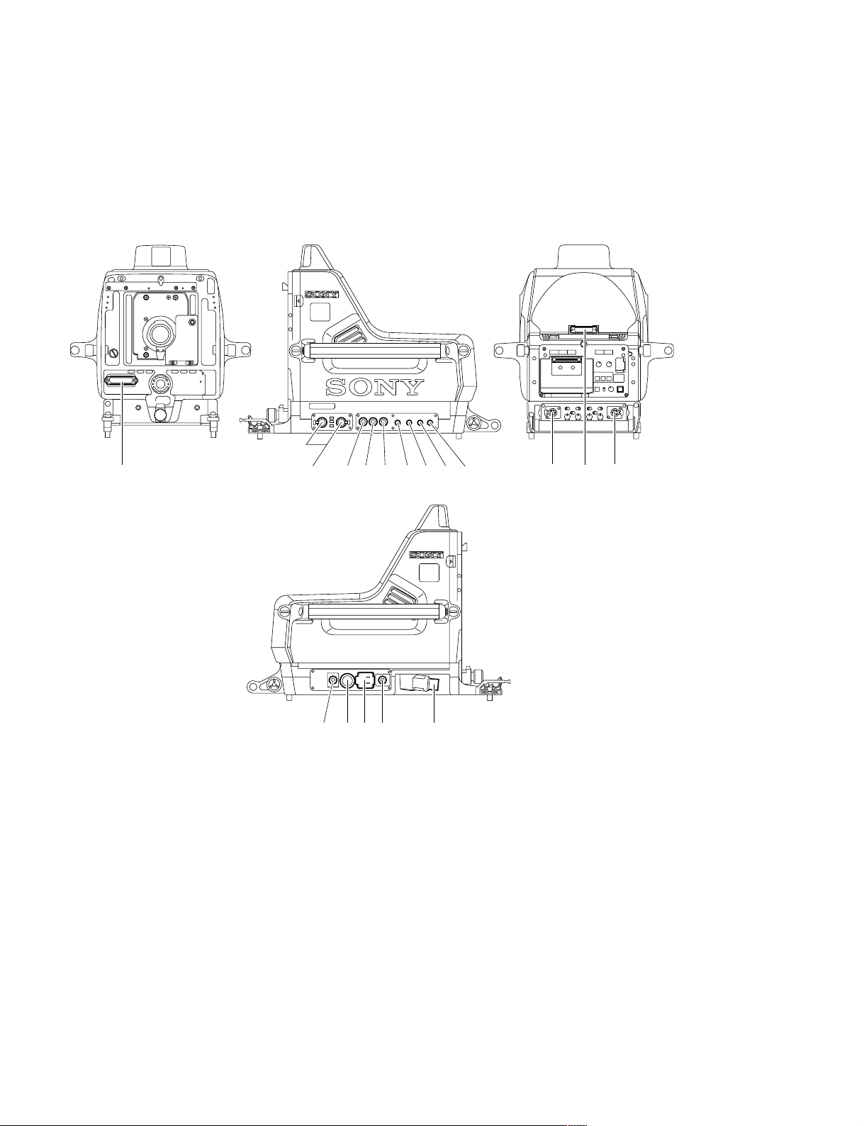
1-2-1. Connector Input/Output Signals
HDC-900/910 Connector Layout
1
1
1
!\ !/ 6 4 3 9 !, 7 8
1
5!] 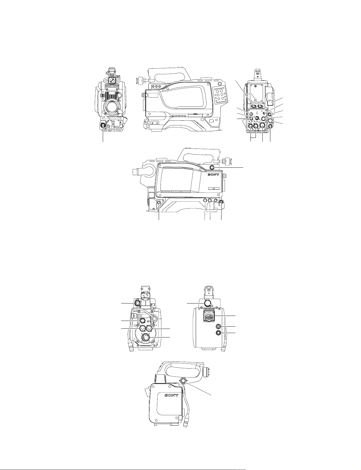
HDC-950/930 Connector Layout
!.
1-2. Connectors and Cables
!-
1
2
*
4
!,
7
9
!'
![
!/
!] 5
!;
8
* : Use 4 connector by selecting PROMPTER OUT, GENLOCK IN and RET IN signals with the switch.
PROMPTER OUT signal become effective when the camera is connected to CCU.
GENLOCK IN and RET IN signals become effective when the camera is used alone.
36!\
HKC-T950 Connector Layout
@-
@[
@-
@=
@=
@\
@]
@/
!\
HDC-900/950 IMM
@[
1-3 (E)
Page 12

1-2. Connectors and Cables
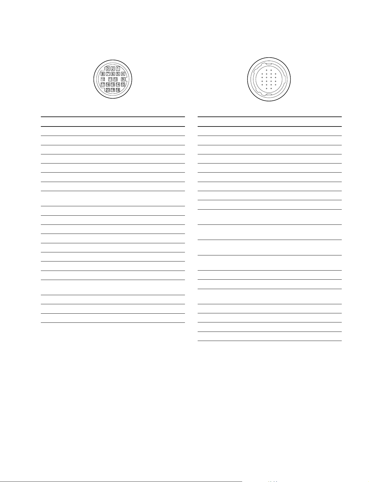
Input/Output Signals
11
1 CCU connector
11
Based upon BTA S-004A/005A/006A 1.485 Gbps
serial
Output Signals
22
2 EARPHONE OUT (HDC-950/930)
22
EARPHONE mini jack
33
3 TEST OUT
33
BNC type 75 Z, 1.0 V p-p
**
*
44
4 PROMPTER OUT
44
**
BNC type 75 Z, 1.0 V p-p
55
5 HD SERIAL DIGITAL OUT
55
Based upon BTA-S004A
BNC type 75 Z, 0.8 V p-p 1.485 Gbps
@/@/
@/ VIDEO OUT (HKC-T950)
@/@/
BNC type 75 Z, 1.0 V p-p
77
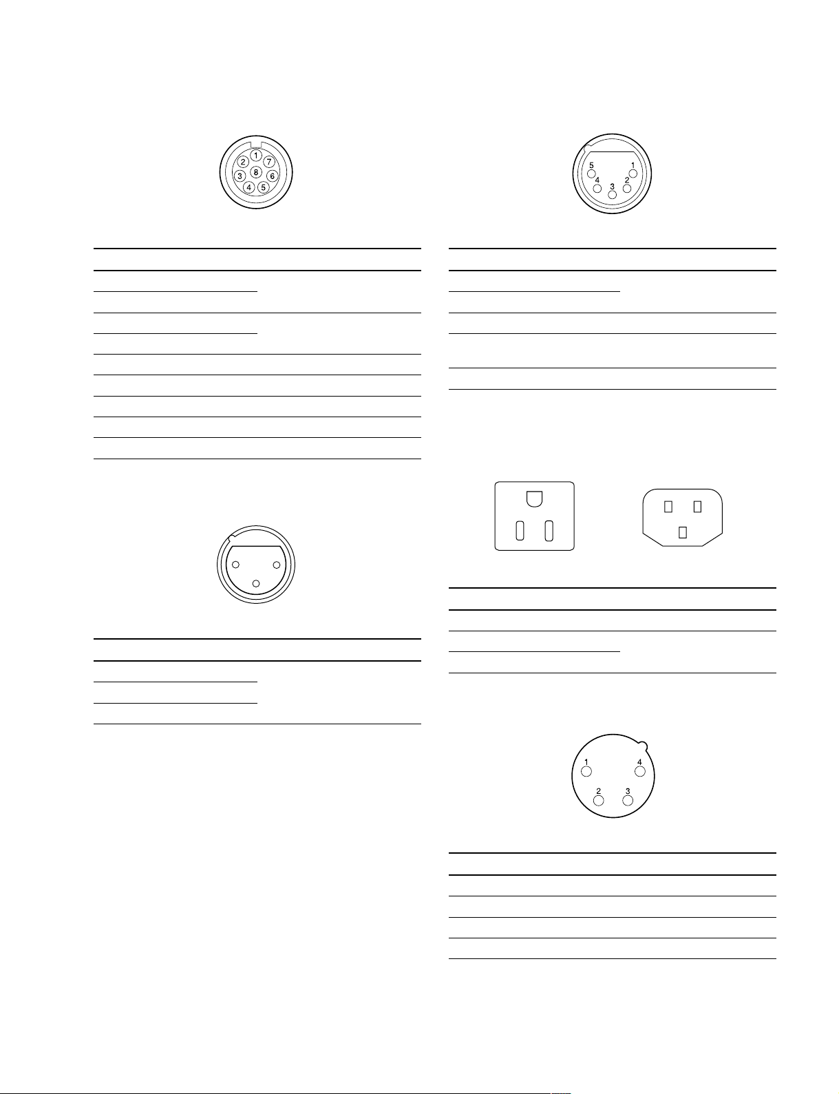
7 RET CONTROL (6P FEMALE)
77
(External view)
No. Signal I/O Specifications
1 INCOM 1 IN Zi > 10 kZ
MIC ON/OFF ON : GND
OFF : OPEN
2 INCOM 2 IN Zi > 10 kZ
MIC ON/OFF ON : GND
OFF : OPEN
3 GND ——
4 NC No connection
5 RET 1 ON/OFF IN Zi > 10 kZ
ON : GND
OFF : OPEN
6 RET 2 ON/OFF IN Zi > 10 kZ
ON : GND
OFF : OPEN
Input Signals
**
*
44
4 GENLOCK IN
44
**
(HDC-950/930)
BNC type 75 Z, 1.0 V p-p
**
*
44
4 RET IN
44
**
(HDC-950/930)
BNC type 75 Z, 1.0 V p-p
66
6 Not used
66
* : Use this connector by selecting PROMPTER OUT, GENLOCK IN and
RET IN signals with the switch on the rear panel of HDC-950/930.
PROMPTER OUT signal become effective when the camera is
connected to CCU.
GENLOCK IN and RET IN signals become effective when the camera is
used alone.
88
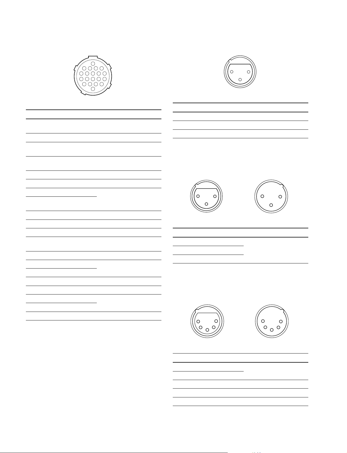
8 DC OUT (4P FEMALE)
88
1
4
23
(External view)
No. Signal I/O Specifications
1 GND —— GND for POWER
2 NC No connection
3 NC No connection
4 UNREG OUT +12 V dc 500 mA (max)
1-4 (E)
HDC-900/950 IMM
Page 13
1-2. Connectors and Cables
99
9 REMOTE (8P FEMALE)
99
(External view)
No. Signal I/O Specifications
1 TX (+) HDC SERIAL DATA
2 TX (_)
3 RX (+) HDCU/MSU/RCP/CNU/VCS
4 RX (_) SERIAL DATA
5 TX GND —— GND for TX
6 POWER (+) OUT +26 V, 200 mA (max)
7 POWER GND —— GND for POWER (+)
8 VIDEO (X) 75 Z, 1.0 V p-p
CHASSIS GND —— CHASSIS GND
!/!/
!/ AUDIO IN CH1/CH2 (3P FEMALE)
!/!/
!-!-
!- INTERCOM CH1/CH2 (5P FEMALE)
!-!-
(External view)
No. Signal I/O Specifications
1 INCOM MIC (Y) IN _20 dBu (CARBON MIC)
2 INCOM MIC (X) IN _60 dBu (DYNAMIC MIC)
3
GND (INCOM/PGM)
4 INCOM OUT 0 dBu
RECEIVE
5 PGM OUT 0 dBu
——
(0 dBu = 0.775 Vrms)
!=!=
!= AC OUT (HDC-900/910)
!=!=
E
HDC-900/910 (CE) only
N
L
21
3
(External view)
No. Signal I/O Specifications
1 AUDIO (G) —— _60 dBu, _50 dBu, _40 dBu,
2 AUDIO (X) IN _30 dBu, _20 dBu, selectable
3 AUDIO (Y) IN High impedance, Balanced
(0 dBu = 0.775 Vrms)
L
No. Signal I/O Specifications
E GND —— CHASSIS GND
N UTL (C) OUT AC 100 V, 200 V or below
L UTL (H) OUT
1-2. Connectors and Cables
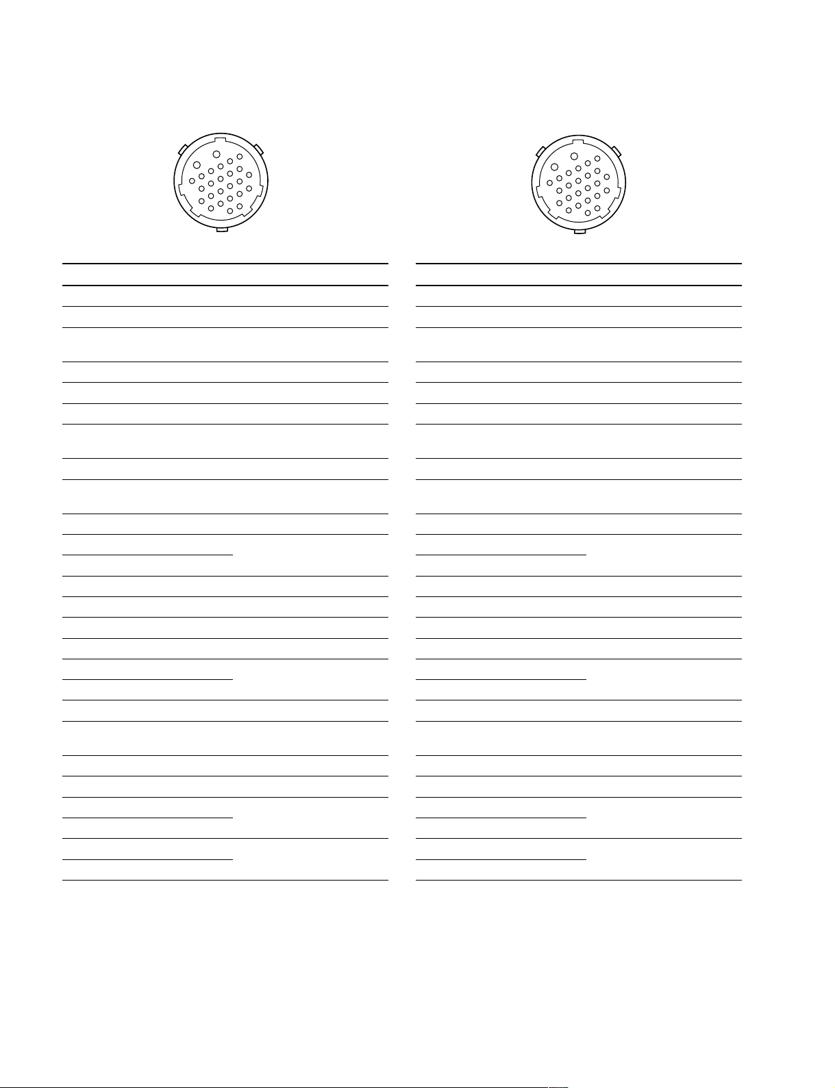
!]!]
!] VTR (26P MALE) (HDC-900/910)
!]!]
B
6
5
A
4
11
3
10
2
1
7
12
17
9
16
8
15
22
14
21
13
20
19
24
18
23
(External view)
No. Signal I/O Specifications
A NC No connection
B VTR CMD GND —— GND for VTR CMD
1 GENLOCK IN Sync 0.6 V p-p, 0 V dc,
Zi = 75 Z
2 GENLOCK GND —— GND for GENLOCK
3 G/Y GND —— GND for G/Y
4 G/Y OUT 1 Vp-p, 0 V dc, Zo = 75 Z
5 R/PR OUT 1 Vp-p/±0.35 V p-p, 0 V dc,
Zo = 75 Z
6 R/PR GND —— GND for R/PR
7 B/PB OUT 1 Vp-p/±0.35 V p-p, 0 V dc,
Zo = 75 Z
8 B/PB GND —— GND for B/PB
9 CH1 MIC (X) OUT _20 dBu, Low impedance,
10 CH1 MIC (Y) OUT Balanced
11 CH1/CH2 MIC GND —— GND for CH1/CH2 MIC
12 NC No connection
13 NC No connection
14 INCOM LINE IN/OUT 0.5 V p-p
15 CH2 MIC (X) OUT _20 dBu, Low impedance,
16 CH2 MIC (Y) OUT Balanced
17 NC No connection
18 RET VIDEO IN 1.0 V p-p, 0 V dc,
Zi = 75 Z
19 RET VIDEO GND —— GND for RET VIDEO
20 AUDIO IN _6 dBu, 750 Z/1 kHz
21 RX COMMAND (X) IN RS-422
22 RX COMMAND (Y) IN
23 TX COMMAND (X) OUT RS-422
24 TX COMMAND (Y) OUT
(0 dBu = 0.775 Vrms)
!]!]
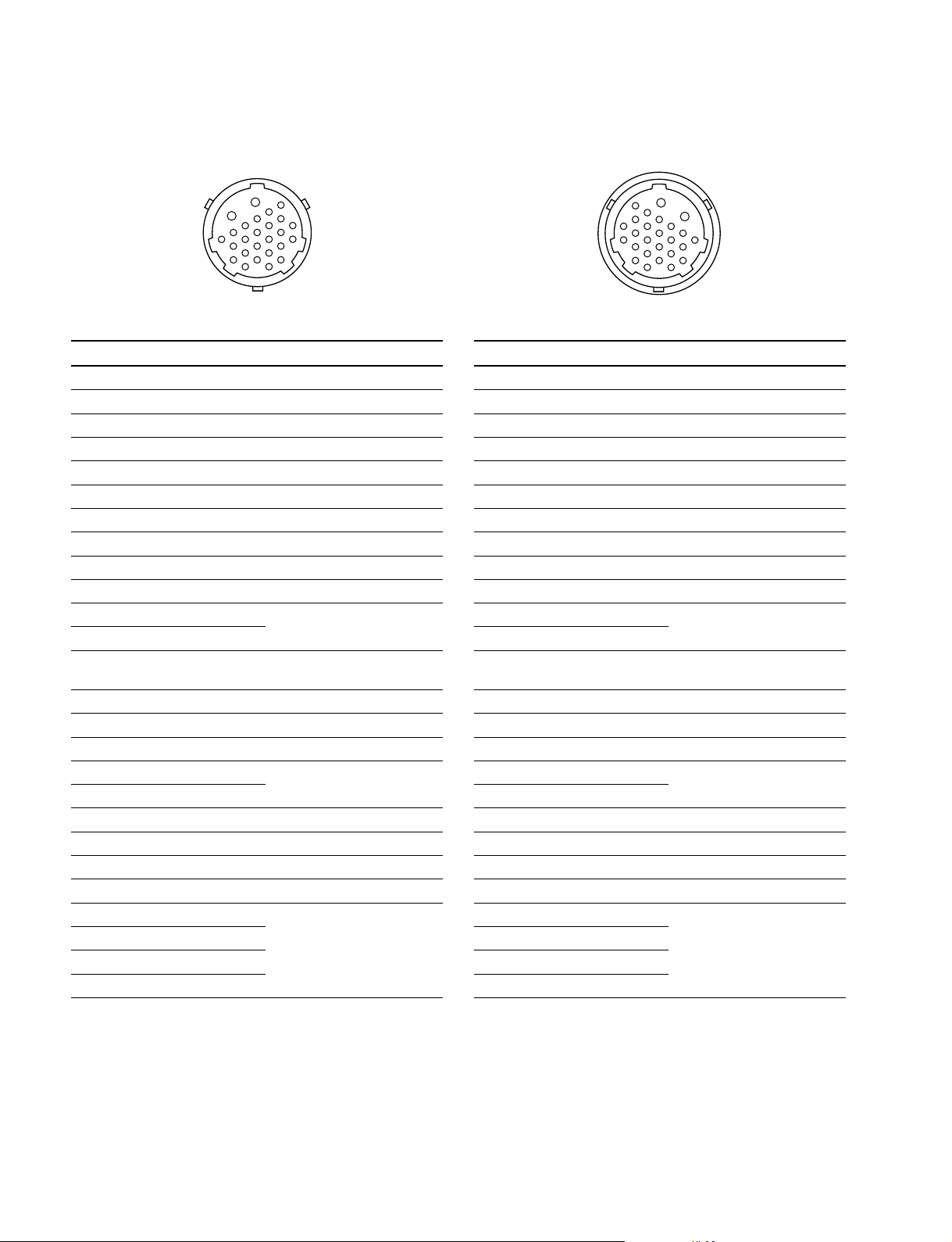
!] VTR (26P MALE) (HDC-950/930)
!]!]
B
6
5
A
4
11
3
10
2
1
7
12
17
9
16
8
15
22
14
21
13
20
19
24
18
23
(External view)
No. Signal I/O Specifications
A VTR UNREG IN +10.5 to 17 V dc
B UNREG GND —— GND for UNREG
1 GENLOCK IN Sync 0.6 V p-p, 0 V dc,
Zi = 75 Z
2 GENLOCK GND —— GND for GENLOCK
3 G/Y GND —— GND for G/Y
4 G/Y OUT 1 V p-p, 0 Vdc, Zo = 75 Z
5 R/PR OUT 1 V p-p/±0.35 V p-p, 0 V dc,
Zo = 75 Z
6 R/PR GND —— GND for R/PR
7B/PB OUT 1 V p-p/±0.35 V p-p, 0 V dc,
Zo = 75 Z
8 B/PB GND —— GND for B/PB
9 CH1 MIC (X) OUT _20 dBu, Low impedance
10 CH1 MIC (Y) OUT Balanced
11 CH1/CH2 MIC GND —— GND for CH1/CH2 MIC
12 UNREG (+) SENSE IN
13 UNREG (_) SENSE IN
14 INCOM LINE IN/OUT 0.5 V p-p
15 CH2 MIC (X) OUT _20 dBu, Low impedance,
16 CH2 MIC (Y) OUT Balanced
17 NC No connection
18 RET VIDEO IN 1.0 V p-p, 0 V dc,
Zi = 75 Z
19 RET VIDEO GND —— GND for RET VIDEO
20 AUDIO IN _6 dBu, 750 Z/1 kHz
21 RX COMMAND (X) IN RS-422
22 RX COMMAND (Y) IN
23 TX COMMAND (X) OUT RS-422
24 TX COMMAND (Y) OUT
(0 dBu = 0.775 Vrms)
1-6 (E)
HDC-900/950 IMM
Page 15
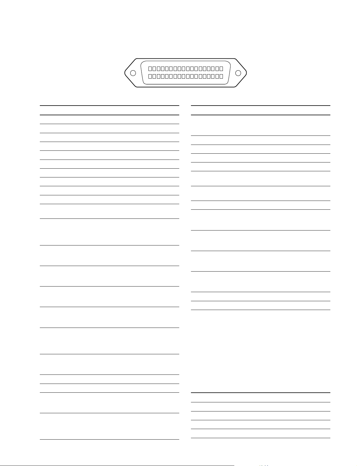
!\!\
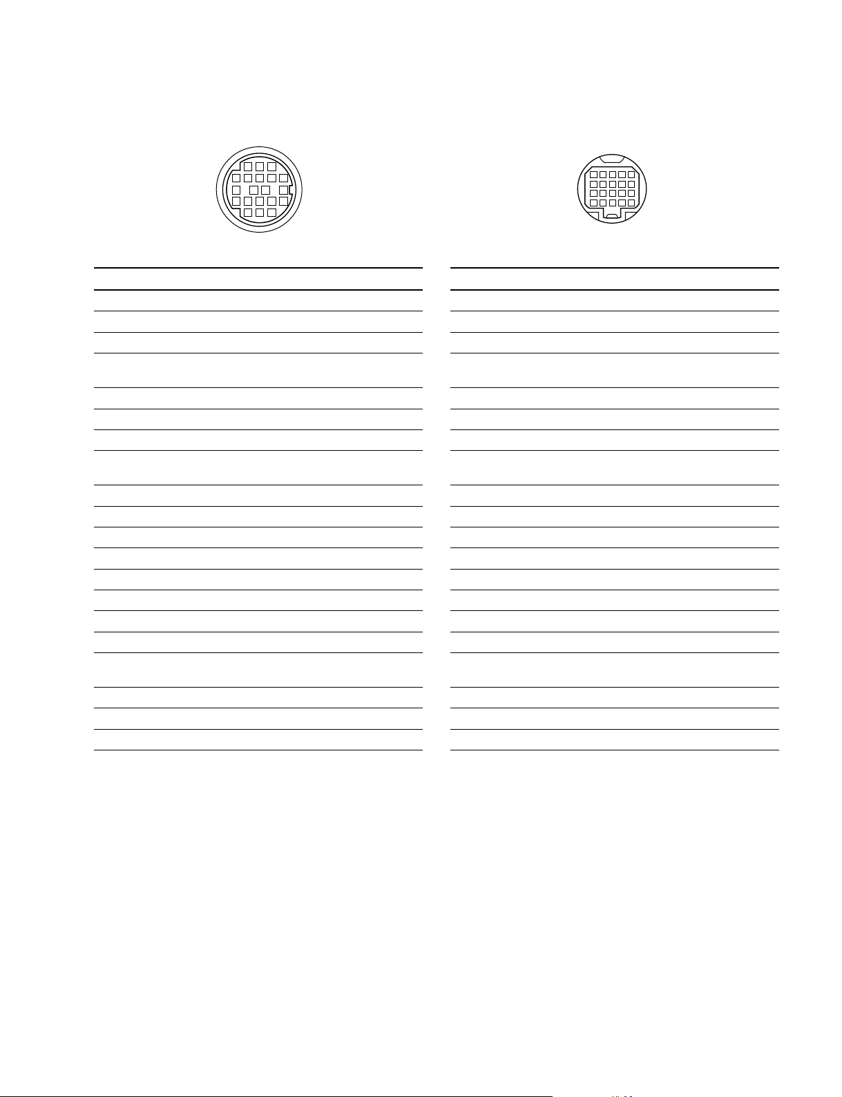
!\ LENS (36P FEMALE) (HDC-900/910)
!\!\
1-2. Connectors and Cables
18
36
No. Signal I/O Specifications
1 NC No connection
2 COMMON 5 V IN No connection
3 NC No connection
4 +12 V (LENS) OUT +12 V (at 2 A)
5 LENS DC GND —— GND for +12 V (LENS)
6 GND (SIG) —— GND
7 NC No connection
8 LENS EXT-1 IN
9 LENS EXT-2 IN
10 LENS EXT-3 IN
*
2
*
2
*
2
11 NC LENS AUX OUT ON : GND
OFF : High impedance
12 IRIS POSI IN Zi > 10 kZ
2 to 7 V
“3.4 ± 0.1 V (F16)”
“6.2 ± 0.1 V (F2.8)”
13 ZOOM POSI IN Zi > 10 kZ
2 to 7 V
“2 V (WIDE), 7 V (TELE)”
14 RET 1 ON IN Zi > 10 kZ
ON : GND
OFF : High impedance
15 RET 2 ON IN Zi > 10 kZ
ON : GND
OFF : High impedance
16 FOCUS POSI IN Zi > 10 kZ
2 to 7 V
“2 V (MIN), 7 V (∞)”
17 IRIS CONT SIG OUT 2 to 7 V
“3.4 ±0.1 V (F16)”
“6.2 ±0.1 V (F2.8)”
Zo < 1 kZ
18 IRIS AUTO OUT AUTO : GND
/MANU MANU : High impedance
Zo < 1 kZ
19 NC No connection
20 NC No connection
21 LENS R TALLY OUT ON : GND
OFF : High impedance
Zo < 1 kZ
22 EXP POSITION IN Zi > 10 kZ
1 to 4 V
1 V : _7.5d
4 V : +7.5d
(External view)
No. Signal I/O Specifications
23 RET 3 ON IN Zi > 10 kZ
24 LENS ADRS 0 IN
25 LENS ADRS 1 IN
26 LENS ADRS 2 IN
27 LENS ADRS 3 IN
28 EXTENDER 1 OUT ON : GND
29 EXTENDER 2 OUT ON : GND
30 F DEM (FAR) IN No connection
31 INCOM 1 IN Zi > 10 kZ
32 INCOM 2 IN Zi > 10 kZ
33 INCOM MIC 1 IN Zi > 10 kZ
34 INCOM MIC 2 IN Zi > 10 kZ
35 F CONT SIG OUT No connection
36 F DEM (NEAR) IN No connection
*
1 Zi > 10 kZ
*
2Zi > 10 kZ
EX1 EX2 EX3 MODE
1 1 1 EXTENDER OFF
1 0 1 EXT-1 (x 1.5) ON
0 1 1 EXT-2 (x 2) ON
0 0 1 EXT-3 (x 2.5) ON
1
19
ON : GND
OFF : High impedance
*
1
*
1
*
1
*
1
ON OFF : High impedance
ON OFF : High impedance
ENG/PRD ENG : GND
PRD : High impedance
ENG/PROD ENG : GND
PRD : High impedance
ON ON : GND
OFF : High impedance
ON ON : GND
OFF : High impedance
1 : High impedance
+0.5
0 : 0
V
_0
LENS ADRS 0 (low-order bit)
LENS ADRS 3 (high-order bit )
1 : High impedance
0 : 0 ±0.5 V
HDC-900/950 IMM
1-7 (E)
Page 16
1-2. Connectors and Cables
!\!\
!\ LENS (12P FEMALE)
!\!\
(HDC-950/930, HKC-T950)
(External view)
No. Signal I/O Specifications
1 RET VIDEO IN ENABLE : 0 V
ENABLE DISABLE : +5 V or OPEN
2 VTR START IN ENABLE : 0 V
/STOP DISABLE : +5 V or OPEN
3 GND —— GND for UNREG
4 AUTO SERVO OUT AUTO : +5 V
5 IRIS CONT OUT +3.4 V (F16) to
6 UNREG OUT +10.5 V to +17 V
7 IRIS POSITION IN +3.4 V (F16) to
8 AUTO/MANU OUT AUTO IRIS : 0 V
9 EXTENDER IN EX 2 ON : GND
ON/OFF EX 0.8 ON : 30 kZ to GND
10 ZOOM IN WIDE : 2 V
POSITION TELE : 7 V
11 FOCUS POSI IN ∞ : 7 V
(/LENS RX) min. : 2 V
12 (LENS TX) OUT
MANU : 0 V or OPEN
+6.2 V (F2.8)
+6.2 V (F2.8)
MANUAL IRIS : +5 V
OFF : OPEN
EX 2 ON
EX 0.8 ON
30 kΩ
!;!;
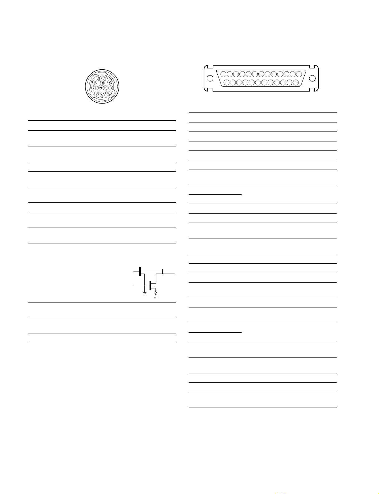
!; VF (25P FEMALE) (HDC-900/910)
!;!;
13 123456789101112
25
(External view)
No. Signal I/O Specifications
1 Y VIDEO (X) OUT 1.0 V p-p, Zo = 75 Z
2PR VIDEO GND —— GND for PR VIDEO
3PR VIDEO (X) OUT 0.7 V p-p, Zo = 75 Z
4PB VIDEO GND —— GND for PB VIDEO
5PB VIDEO (X) OUT 0.7 V p-p, Zo = 75 Z
6 PEAKING IN 0 to 5 V dc
LEVEL
7 +12 V OUT +10.5 to +20 V
8 +12 V
9 NC No connection
10 S-DATA IN/OUT TTL level
11 R TALLY OUT ON : +5 V
12 EFFECT OUT ON : +5 V
13 NC No connection
14 Y VIDEO GND —— GND for Y VIDEO
15 S-CK OUT TTL level
16 BATT IND OUT ON : +5 V
17 CHASSIS GND ——
18 G TALLY OUT ON : +5 V
19 GND (+12 V) —— GND for +12 V
20 GND (+12 V)
21 VF-SEL IN BW : 0 V
22 H EXPAND OUT ON : GND
23 NC No connection
24 NC No connection
25 V EXPAND OUT ON : GND
1415161718192021222324
OFF : 0 V
OFF : 0 V
OFF : 0 V
OFF : 0 V
COLOR : +5 V
OFF : +5 V
OFF : +5 V
1-8 (E)
HDC-900/950 IMM
Page 17
1-2. Connectors and Cables
!;!;
!; VF (20P FEMALE) (HDC-950/930)
!;!;
(External view)
No. Signal I/O Specifications
1 S-DA TA IN/OUT TTL level
2 NC No connection
3 NC No connection
4 SCK OUT TTL level
5 NC No connection
6 NC No connection
7 NC No connection
8 G TALLY OUT ON : 5 V
OFF : GND
9 NC No connection
10 NC No connection
11 NC No connection
12 Y VIDEO OUT 1.0 V p-p, Zo = 75 Z
13 VIDEO GND —— GND for VIDEO
14 Pb VIDEO OUT ±0.35 V p-p, Zo = 75 Z
15 Pr VIDEO OUT ±0.35 V p-p, Zo = 75 Z
16 NC No connection
17 R TALLY OUT ON : 5 V
OFF : GND
18 NC No connection
19 UNREG GND —— GND for UNREG
20 UNREG OUT +10.5 V to +17 V
!'!'
!' EXT I/O (20P) (HDC-950/930)
!'!'
11
5
17
18
19
20
1
2
3
4
10
16
(External view)
No. Signal I/O Specifications
1 Y VIDEO (X) OUT 1.0 V p-p, Zo = 75 Z
2 Y VIDEO (G) —— GND for Y VIDEO
3 PROMPTER (X) OUT 1.0 V p-p, Zo = 75 Z
4 PROMPTER (G) —— GND for PROMPTER
5 Pr VIDEO (X) OUT ±0.35 V p-p, Zo = 75 Z
6 Pr VIDEO (G) —— GND for Pr VIDEO
7 Pb VIDEO (X) OUT ±0.35 V p-p, Zo = 75 Z
8 Pb VIDEO (G) —— GND for Pb VIDEO
9 SDA VF IN/OUT TTL level
10 VD OUT Negative Pulse,
3.0 V p-p, Low impedance
11 CALL ON IN ON : L (0 v)
OFF : H (+3 V)
12 VF POWER OFF OUT ON : H (+5 V)
OFF : L (0 V)
13 MAIN POWER OUT ON : +8 V
ON/OFF OFF : GND
14 SCL VF OUT TTL level
15 TALLY GND —— GND for TALLY
16 BACK TALLY OUT ON : 5 V
OFF : GND
17 PANEL DATA IN RX SERIAL DATA
18 PANEL DATA OUT TX SERIAL DATA
19 VF UNREG + OUT
+12 V (+10.5 V to +17.0 V)
20 GND —— GND for UNREG
HDC-900/950 IMM
1-9 (E)
Page 18
1-2. Connectors and Cables
!,!,
!, TRACKER (FEMALE)
!,!,
1
2
6
11
16
5
3
4
7
8139
12
10
14
15
17
182019
(External view)
No. Signal I/O Specifications
1 TRK R (X) OUT TRACKER RECEIVE
0 dBu unbalanced
2 TRK R (G) —— GND for TRACKER R
3 GND —— GND for UNREG/TALLY
(UNREG/TALLY)
4 R TALLY OUT ON : 5 V (Open Collector)
OFF : 0 V (Open Collector)
5 TRK PGM (G) —— GND for PGM
6 UNREG OUT +12 V (+10.5 to +17.0 V)
7 TRK T (X) IN TRACKER TALK
8 TRK T (Y) IN 0 dBu /_20 dBu
High impedance balanced
9 TRK T (G) —— GND for TRACKER T
10 TRK PGM (X) OUT _20 dBu unbalanced
11 NC No connection
12 G TALLY OUT ON : 5 V (Open Collector)
OFF : 0 V (Open Collector)
13 NC No connection
14 RX_DATA (0) IN TRUNK DATA IN, RS232-C
15 RX_DATA (1) IN
16 NC No connection
17 NC No connection
18 TX_DATA (0) OUT
TRUNK DATA OUT, RS232-C
19 TX_DATA (1) OUT
20 GND ——
(0 dBu = 0.775 Vrms)
!.!.
!. FRONT MIC (3P FEMALE) (HDC-950/930)
!.!.
21
3
(External view)
No. Signal I/O Specifications
1 CHU MIC (G) —— _60 dBu, _50 dBu, _40 dBu,
2 CHU MIC (X) IN _30 dBu, _20 dBu, selectable
3 CHU MIC (Y) IN High impedance, Balanced
(0 dBu = 0.755 Vrms)
@-@-
@- MIC (HKC-T950)
@-@-
(3P FEMALE) (3P MALE)
21
3
1
(External view) (External view)
No. Signal I/O Specifications
1 AUDIO (G) —— _60 dBu, _50 dBu, _40 dBu,
2 AUDIO (X) IN _30 dBu, _20 dBu, selectable
3 AUDIO (Y) IN High impedance, Balanced
2
3
(0 dBu = 0.755 Vrms)
@=@=
@= INCOM (HKC-T950)
@=@=
(5P FEMALE) (5P MALE)
5
1
2
4
3
1
5
4
2
3
1-10 (E)
(External view) (External view)
No. Signal I/O Specifications
1 INCOM MIC (Y) IN _20 dBu (CARBON MIC)
2 INCOM MIC (X) IN _60 dBu (DYNAMIC MIC)
3 GND (INCOMPGM) ——
4 INCOM RECEIVE OUT 0 dBu
5 PGM OUT 0 dBu
(0 dBu = 0.755 Vrms)
HDC-900/950 IMM
Page 19
@[@[
@[ VF (HKC-T950)
@[@[
(20P FEMALE)
1-2. Connectors and Cables
(20P FEMALE)
123
12 11 10 9
17 16 15
45678
141813
20
19
(External view)
No. Signal I/O Specifications
1 S DATA IN/OUT TTL level
2 NC No connection
3 NC No connection
4 SCK OUT TTL level
MANU : 0 V or OPEN
5 NC No connection
6 NC No connection
7 NC No connection
8 G TALLY OUT ON : 5 V
OFF : GND
9 NC No connection
10 NC No connection
11 NC No connection
12 Y VIDEO OUT 1.0 V p-p, Zo = 75 Z
13 VIDEO GND —— GND for VIDEO
14 NC No connection
15 NC No connection
16 NC No connection
17 R TALLY OUT ON : 5 V
OFF : GND
18 NC No connection
19 UNREG GND —— GND for UNREG
20 UNREG OUT +10.5 V to +1.7 V
12345
678910
11 12 13 14 15
16 17 18 19 20
(External view)
No. Signal I/O Specifications
1 S DATA IN/OUT TTL level
2 NC No connection
3 NC No connection
4 SCK IN TTL level
MANU : 0 V or OPEN
5 NC No connection
6 NC No connection
7 NC No connection
8 G TALLY IN ON : 5 V
OFF : GND
9 NC No connection
10 NC No connection
11 NC No connection
12 Y VIDEO IN 1.0 V p-p, Zi = 75 Z
13 VIDEO GND —— GND for VIDEO
14 NC No connection
15 NC No connection
16 NC No connection
17 R TALLY IN ON : 5 V
OFF : GND
18 NC No connection
19 NC No connection
20 NC No connection
HDC-900/950 IMM
1-11 (E)
Page 20
1-2. Connectors and Cables
@]@]
@] CAM BODY (HKC-T950)
@]@]
(26P MALE)
B
6
5
A
4
11
3
2
1
8
7
13
12
18
(External view)
No. Signal I/O Specifications
A UNREG IN 13 V to 17 V
B UNREG GND —— GND for UNREG
1 OHB H OUT 0.3 V p-p Positive pulse
2 OHB H (G) —— GND for OHB H
3 G VIDEO (G) —— GND for G VIDEO
4 G VIDEO (X) OUT
5 R VIDEO (X) OUT
6 R VIDEO (G) —— GND for R VIDEO
7 B VIDEO (X) OUT 95 mV p-p, Zo = 75 Z (100 %)
8 B VIDEO (G) —— GND for B VIDEO
9 MIC (X) OUT _60 dBu, _50 dBu, _40 dBu,
10 MIC (Y) OUT _30 dBu, _20 dBu, selectable
11 INCOM/MIC GND —— GND for INCOM/MIC,
12 IRIS CONT IN +3.4 V (F16) to +6.2 V (F2.8)
13 CHU F IN 0.3 V p-p Positive pulse
14 INCOM RECEIVE IN 0 dBu
15 INCOM MIC (X) OUT _20 dBu (CARBON MIC)
16 INCOM MIC (Y) OUT _60 dBu (DYNAMIC MIC)
17 CHU H IN 150 mV p-p Positive pulse
18 VF VIDEO (X) IN 180 mV p-p, Zi = 75 Z
19 VF VIDEO (G) —— GND for VF VIDEO,CHU H
20 PGM IN 0 dBu
21 RX COMMAND (X) IN
22 RX COMMAND (Y) IN 340 mV p-p
23 TX COMMAND (X) OUT
24 TX COMMAND (Y) OUT
17
10
16
9
22
15
14
21
20
19
24
23
300 mV p-p, Zo = 75 Z (100 %)
300 mV p-p, Zo = 75 Z (100 %)
CHU F, IRIS CONT
@\@\
@\ OPT HEAD (HKC-T950)
@\@\
(26P FEMALE)
B
6
5
11
17
16
22
21
24
(External view)
No. Signal I/O Specifications
A UNREG OUT 13 V to 17 V
B UNREG GND —— GND for UNREG
1 OHB H IN 0.3 V p-p Positive pulse
2 OHB H (G) —— GND for OHB H
3 G VIDEO (G) —— GND for G VIDEO
4 G VIDEO (X) IN 300 mV p-p, Zi = 75 Z (100 %)
5 R VIDEO (X) IN 300 mV p-p, Zi = 75 Z (100 %)
6 R VIDEO (G) —— GND for R VIDEO
7 B VIDEO (X) IN 95 mV p-p, Zi = 75 Z (100 %)
8 B VIDEO (G) —— GND for B VIDEO
9 MIC (X) IN _60 dBu, _50 dBu, _40 dBu,
10 MIC (Y) IN _30 dBu, _20 dBu, selectable
11 INCOM/MIC GND —— GND for INCOM/MIC,
12 IRIS CONT OUT +3.4 V (F16) to +6.2 V (F2.8)
13 CHU F OUT 0.3 V p-p Positive pulse
14 INCOM RECEIVE OUT 0 dBu
15 INCOM MIC (X) IN _20 dBu (CARBON MIC)
16 INCOM MIC (Y) IN _60 dBu (DYNAMIC MIC)
17 CHU H OUT 150 mV p-p Positive pulse
18 VF VIDEO (X) OUT 180 mV p-p, Zo = 75 Z
19 VF VIDEO (G) —— GND for VF VIDEO, CHU H
20 PGM OUT 0 dBu
21 RX COMMAND (X) OUT
22 RX COMMAND (Y) OUT 340 mV p-p
23 TX COMMAND (X) IN
24 TX COMMAND (Y) IN
A
4
3
10
2
9
15
20
23
1
8
7
14
13
12
19
18
CHU F, IRIS CONT
1-12 (E)
HDC-900/950 IMM
Page 21
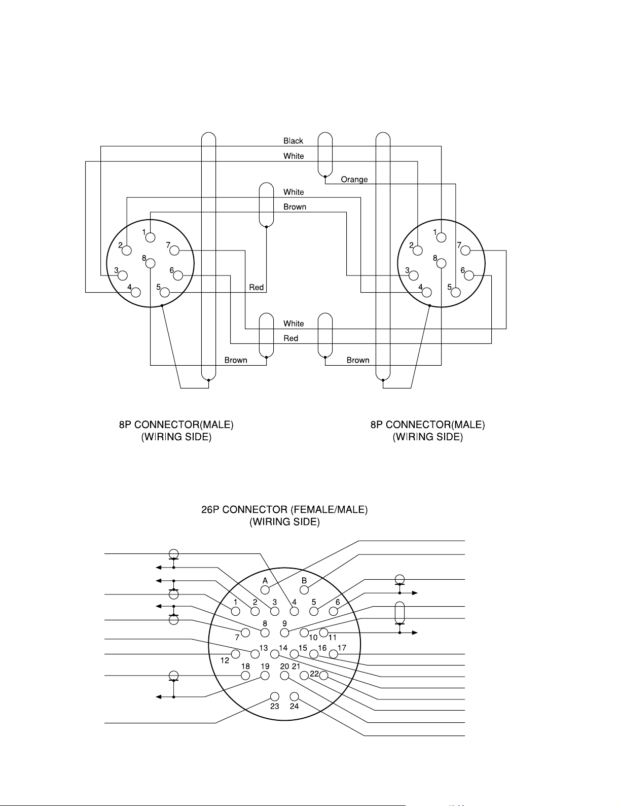
1-2-2. Wiring Diagrams for Cables
CCA-5 Cable
1-2. Connectors and Cables
HDCZ Cable
Yellow
Black
Blue
Red
Brown
Gray
Red
Black
White
Red
Red
White
Blue
Red
White
Orange
White
Red
Yellow
White
HDC-900/950 IMM
1-13 (E)
Page 22

1-2. Connectors and Cables
1-2-3. Connection Connectors/Cables
Connection made with the connector panels during installation or service, should be made with the connectors/
complete cable assemblies specified in the following list,
or equivalent parts.
Indication Connection connector/cable
TEST OUT 1-569-370-12 Plug, BNC
PROMPTER
SERIAL OUT
VIDEO OUT
(BNC)
AUDIO IN 1-508-084-00 XLR, 3P Male or
MIC IN ITT Cannon XLR-3-12C equivalent
(3P FEMALE) Cable assembly
MIC IN 1-508-083-00 XLR, 3P, Female or
(3P MALE) ITT Cannon XLR-3-11C equivalent
RET CONTROL 1-560-078-00 Plug, 6P Male or
(6P FEMALE) HIROSE HR10-7PA-6P equivalent
DC OUT 1-566-425-11 Plug, 4P Male or
(4P FEMALE) HIROSE HR10A-7P-4P equivalent
INTERCOM 1-508-370-11 XLR, 5P Male or
INCOM ITT Cannon XLR-5-12C equivalent
(5P FEMALE) Cable assembly
INCOM 1-508-363-00 XLR, 5P Female or
(5P MALE) ITT Cannon XLR-5-11C equivalent
VTR 1-564-184-00 Plug, 26P Female or
CAM BODY Cable assembly
OPT HEAD 1-564-183-31 Plug, 26P Male or
(26P FEMALE) Cable assembly
DC IN 1-508-362-00 XLR, 4P Female or
(4P MALE) ITT Cannon XLR-4-11C equivalent, or
(supplied with HKC-T950, 0.8 m)
1-823-599-11
Cable assembly
(supplied with HKC-T950, 0.8 m)
1-823-599-11
(supplied with HKC-T950, 0.8 m)
1-823-600-11
Cable assembly
(supplied with HKC-T950, 0.8 m)
1-823-600-11
HDCZ-A10
(supplied with HKC-T950, 10 m)
1-823-615-11
HDCZ-A25 (option, 25 m)
1-823-616-11
HDCZ-A50 (option, 50 m)
1-823-617-11
HDCZ-A10
(supplied with HKC-T950, 10 m)
1-823-615-11
HDCZ-A25 (option, 25 m)
1-823-616-11
HDCZ-A50 (option, 50 m)
1-823-617-11
Cable assembly 1-551-577-00
(Supplied with AC-550/550CE)
*3
*3
*3
*3
*3
*3
Indication Connection connector/cable
REMOTE 1-766-848-11 Plug, 8P Male or
(8P FEMALE) CCA-5 cable assembly (option)
CCA-5-10 (10 m) /CCA-5-3 (3 m) or
REMOTE cable 1-783-372-11
(supplied with RM-B150, 10 m)
TRACKER HIROSE HR25-9P-20P equivalent
(20P FEMALE)
VF Cable assembly
(20P FEMALE) (supplied with HKC-T950, 0.7 m)
1-792-603-21
*1: Use of REMOTE cable enables to monitor video signals.
*2: If using a cable of length different from a standard product, contact your
local Sony Sales Office/Service Center.
*3: Only for HKC-T950.
*2
*1 *2
1-2-4. Note in connecting CCU connector
It is recommendable to clean the optical contact portions
mentioned below before connecting this unit to the camera
control unit.
. CCU connector of this unit
. Camera connector of the camera control unit
. Optical/Electrical cable
It is also necessary to clean the optical contact portions
mentioned below before using the HDC-950/930 to the
large lens adaptor CA-905L.
. CA cable of a large lens adaptor
. CCU connector of a large lens adaptor
For details on a cleaning method, refer to Section 2-1
“Cleaning of Connector/Cable”.
1-14 (E)
HDC-900/950 IMM
Page 23
1-3. Location of Printed Circuit Boards
HDC-900/910
1-3. Location of Printed Circuit Boards
CN-2073
SW-1019
CN-1702
CN-1974
SW-1020
CN-2016
PS-582
CN-1956
RX-28
AT-131
MB-883
CN-986
RE-184
RE-182
LE-172
RE-181
DU-104
AU-271
AT-130
SG-268
DAP-24
DAD-37
VDA-55
DPR-156
DPR-154
VA-196
SDI-49
IF-784
SW-1045
CN-2074
CN-1961
RP-114
DU-69
TG-214
BI-145
DR-412
SERVO DRIVER
NR-69/73
PA-239
CN-2015
CN-1947
BI-145
CN-1998
CN-1961
CN-2017
RP-114
DU-69
TG-214
BI-150
DR-492
SERVO DRIVER
CN-2329
BI-150
NR-73
PA-239
HDC-900/950 IMM
HDC-900 HDC-910
1-15 (E)
Page 24
1-3. Location of Printed Circuit Boards
HDC-950/930
DPR-156
CN-2018
SW-1018
CN-1954
CN-1953
LP-113
RE-188
CN-1952
DU-104
RE-182
RE-184
CN-1702B
CN-2094
SW-1016
MB-882
CN-2026
SW-1029
BI-145
RX-28
DU-69
SW-1013
PA-239
NR-69/73
TG-214
SW-1015
RP-114
DR-412
SERVO DRIVER
SDI-49
SW-1014
VA-196
CN-1964
VDA-55
DPR-154
BI-150
DAP-24
DAD-37
DU-69
AT-130
SG-268
PA-239
AU-271
NR-69/73
TG-214
CN-1702B
SW-1017
SW-1027
CN-1951
CN-2063
CN-1955
RE-181
RP-114
DR-492
SERVO DRIVER
1-16 (E)
BI-145
HDC-950
CN-1947
CN-1961
BI-150
CN-1961
CN-2329
HDC-930
HDC-900/950 IMM
Page 25
HKC-T950
1-3. Location of Printed Circuit Boards
LE-256CN-2270
AT-146
IF-845
SW-1065 SW-1066
CN-2271
RE-202
CN-2202
SW-1076
CN-2264
AT-147
CN-2203
IF-846
CN-2265
HDC-900/950 IMM
1-17 (E)
Page 26
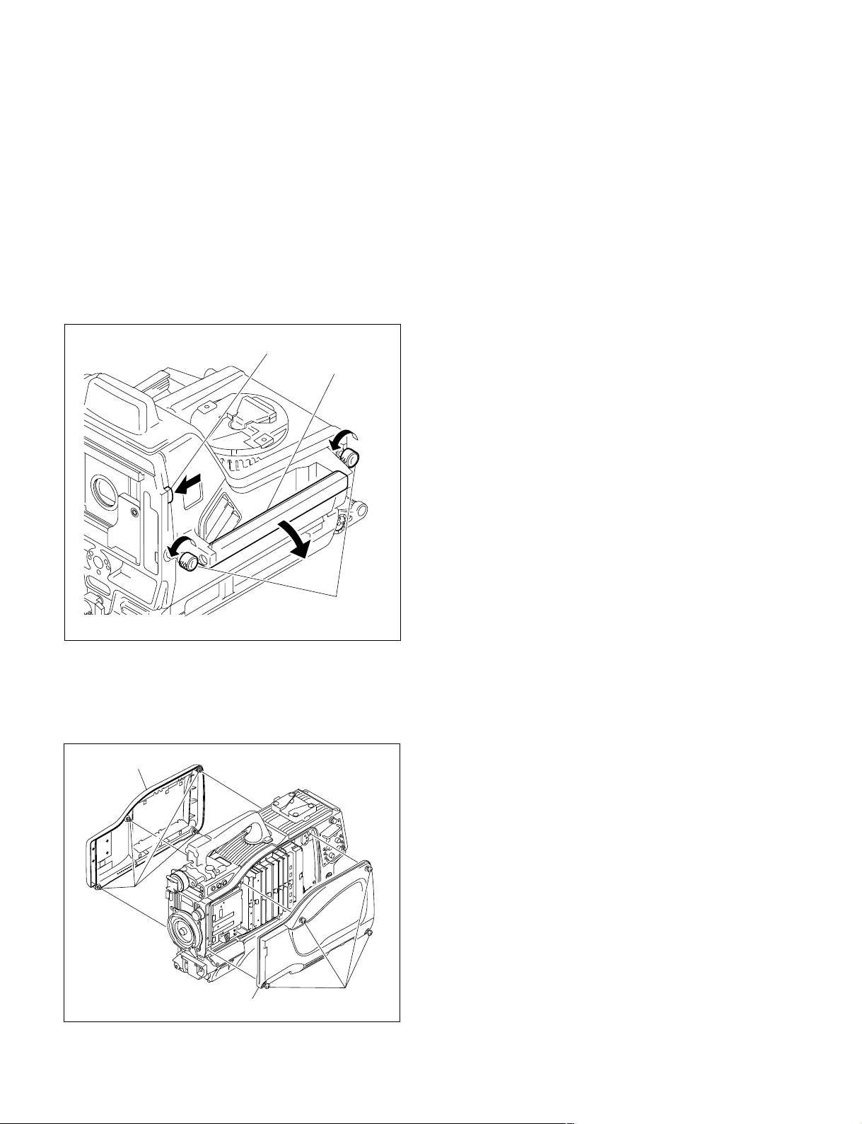
1-4. Opening/Closing the Side Panel
1-4. Opening/Closing the Side Panel
HDC-900/910
1. Unscrew the two lock screws of the side panel.
2. While sliding the safety lock toward the lens, open the
side panel by holding the handle.
3. Close the side panel and tighten securely the lock
screws of the side panel.
[Reference][Reference]
[Reference]
[Reference][Reference]
Closing the side panel brings the safety lock to an
automatic locking.
Safety lock
Handle
Lock screw of the
side panel
HDC-950/930
1. Unscrew the eight screws as shown in the figure, then
remove the inside panel and outside panel.
2. Reinstall in the reverse order of removal step 1.
Outside panel
Screws
Inside panel
Screws
1-18 (E)
HDC-900/950 IMM
Page 27
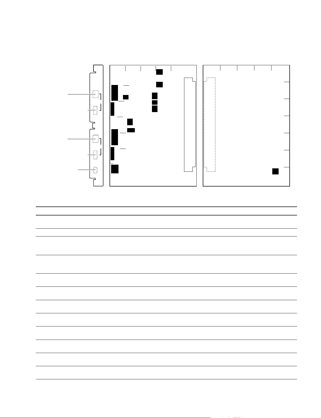
S104
S103
S1
S101
AU-271 board (A side)
S102
S201
S2
S202
S301
S304
S203
S204
S303
B
C
D
E
F
G
A
54 3 2 1
AU
CM
DYN
INCOM 1
INCOM 1 switch
INCOM 1 MIC GAIN switch
MIC GAIN
DYN
INCOM 2
MIC GAIN
MIC
MONITOR
ON
+
0
_
+
0
_
OFF
INCOM 2 switch
INCOM 2 MIC GAIN switch
MIC MONITOR switch
AU-271 board suffix -13 and higher
(B side)
S300
1
A
B
C
D
E
F
G
2345
1-5. Switch Setting on the Boards
AU-271 board
1-5. Switch Setting on the Boards
Ref. No. Name Contents Factory Setting
S1-1
S1-2
S2-1
S2-2 PGM2 INCOM2 RECEIVE Switch ON to mix the PGM2 signal adjusted the sound volume OFF
S101-1 PGM1 MUTE ON/OFF Switch OFF to output the PGM1 signal to the PGM OUT of the OFF
S101-2 PGM2 MUTE ON/OFF Switch OFF to output the PGM2 signal to the PGM OUT of the ON
S101-3 INCOM1 MUTE ON/OFF Switch OFF to output the INCOM1 RECEIVE signal to the PGM OUT OFF
S101-4 INCOM2 MUTE ON/OFF Switch OFF to output the INCOM2 RECEIVE signal to the PGM OUT ON
S102-1 PGM1 MUTE ON/OFF Switch OFF to output the PGM1 signal to the INCOM OUT of OFF
S102-2 PGM2 MUTE ON/OFF Switch OFF to output the PGM2 signal to the INCOM OUT of ON
S102-3 INCOM1 MUTE ON/OFF Switch OFF to output the INCOM1 RECEIVE signal to the INCOM OFF
S102-4 INCOM2 MUTE ON/OFF Switch OFF to output the INCOM2 RECEIVE signal to the INCOM ON
HDC-900/950 IMM
*1
TRACKER INCOM2 ON/OFF Switch ON to mix the TRACKER TALK signal of the Tracker OFF
connector to CCU INCOM2 RECEIVE OUT.
*2
*2
Not used —— ——
PGM1 INCOM1 RECEIVE Switch ON to mix the PGM1 signal adjusted the sound volume by OFF
MIX ON/OFF the PGM volume control to the INCOM1 RECEIVE signal before
the sound volume adjustment.
MIX ON/OFF by the PGM volume control to the INCOM2 RECEIVE signal before
the sound volume adjustment.
INTERCOM1 connector.
INTERCOM1 connector.
of the INTERCOM1 connector.
of the INTERCOM1 connector.
the INTERCOM1 connector.
the INTERCOM1 connector.
OUT of the INTERCOM1 connector.
OUT of the INTERCOM1 connector.
1-19 (E)
Page 28

1-5. Switch Setting on the Boards
Ref. No. Name Contents Factory Setting
S103 INCOM1 MIC GAIN +/0/_ Select the audio level of INTERCOM1/2 to be sent to CCU. 0
+ :+6dB
0 : 0dB
_ :_6dB
S104 INCOM1 MIC TYPE Select from two options below in accordance with the microphone CM
of the head set connected to the INTERCOM1/2 connector.
CM : Carbon microphone
DYN :Dynamic microphone
S201-1 PGM1 MUTE ON/OFF Switch OFF to output the PGM1 signal to the PGM OUT of the ON
INTERCOM2 connector.
S201-2 PGM2 MUTE ON/OFF Switch OFF to output the PGM2 signal to the PGM OUT of OFF
the INTERCOM2 connector.
S201-3 INCOM1 MUTE ON/OFF Switch OFF to output the INCOM1 RECEIVE signal to the PGM ON
OUT of the INTERCOM2 connector.
S201-4 INCOM2 MUTE ON/OFF Switch OFF to output the INCOM2 RECEIVE signal to the PGM OFF
OUT of the INTERCOM2 connector.
S202-1 PGM1 MUTE ON/OFF Switch OFF to output the PGM1 signal to the INCOM OUT of the ON
INTERCOM2 connector.
S202-2 PGM2 MUTE ON/OFF Switch OFF to output the PGM2 signal to the INCOM OUT of the OFF
INTERCOM2 connector.
S202-3 INCOM1 MUTE ON/OFF Switch OFF to output the INCOM1 RECEIVE signal to the INCOM ON
OUT of the INTERCOM2 connector.
S202-4 INCOM2 MUTE ON/OFF Switch OFF to output the INCOM2 RECEIVE signal to the INCOM OFF
OUT of the INTERCOM2 connector.
S203 INCOM2 MIC GAIN +/0/_ Select the audio level of the INTERCOM1/2 to be sent to CCU. 0
+ :+6dB
0 : 0dB
_ :_6dB
S204 INCOM2 MIC TYPE Select from two options below in accordance with the microphone of CM
the head set connected to the INTERCOM 1/2 connector.
CM : Carbon microphone
DYN :Dynamic microphone
*3
S300-1
AUDIO1 +12 V OFF/ON Switch ON to supply +12 V for MIC POWER to the microphone OFF
connected the AUDIO IN 1 connector.
*3
S300-2
AUDIO2 +12 V OFF/ON Switch ON to supply +12 V for MIC POWER to the microphone OFF
connected the AUDIO IN 2 connector.
S301-1 TRACKER RECEIVE OUT Switch ON to mix the PGM1 signal to the TRACKER RECEIVE OUT OFF
PGM1 MIX of the TRACKER connector.
S301-2 TRACKER RECEIVE OUT Switch ON to mix the PGM2 signal to the TRACKER RECEIVE OUT OFF
PGM2 MIX of the TRACKER connector.
*1
S301-3
TRACKER RECEIVE OUT Switch ON to mix the INCOM2 RECEIVED signal to the TRACKER OFF
IMCOM2 RECEIVE MIX RECEIVE OUT of the TRACKER connector.
*1
S301-4
TRACKER RECEIVE OUT Switch ON to mix the INCOM2 TALK signal to the TRACKER OFF
INCOM2 TALK MIX RECIVE OUT of the TRACKER connector.
S303 MIC MONITOR ON/OFF Switch ON to monitor the microphone input signal at the INCOM OUT OFF
or EARPHONE OUT.
S304 TRACKER (T) 0/_20 Select the input level of the TRACKER Connector. 0
0 : 0dBu
_20 : _20dBu
(0dBu = 0.775 Vrms)
1-20 (E)
HDC-900/950 IMM
Page 29
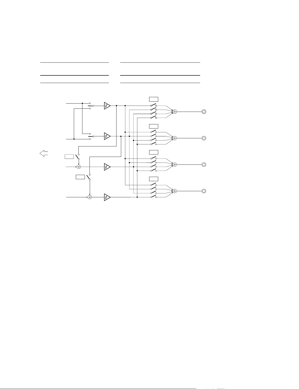
1-5. Switch Setting on the Boards
*1: The Tracker connector communicates to INCOM1 at the standard setting, yet it is communicable to INCOM2 by setting S1-1, S301-1
and S301-4
to ON.
*2: When setting S2-1 or S2-2 to ON, set bit1 and bit2 of S101, S102, S201 and S202 as shown below to prevent PGM1 and PGM2
signals from being mixed double.
S2-1 S101, 102, 201, 202 S2-2 S101, 102, 201, 202
bit1 bit12
ON ON ON ON
INCOM1
PGM 1
PGM 2
PGM1/2 swiitch
(Panel)
INCOM2
PGM1/2 swiitch
(Panel)
bit1
bit2
bit3
bit4
bit1
bit2
bit3
bit4
S101
S102
PGM OUT
INCOM OUT
INTERECOM CH1
INTERECOM CH1
CCU
S2-1
INCOM1
S2-2
INCOM2
bit1
bit2
bit3
bit4
bit1
bit2
bit3
bit4
S201
S202
PGM OUT
INCOM OUT
INTERECOM CH2
INTERECOM CH2
n
Each bit of S101, S102, S103 and S104 is opened when it is set to “ON” position.
Set to “OFF”position to close the switch.
*3: AU-271 board suffix -13 and higher.
HDC-900/950 IMM
1-21 (E)
Page 30

1-5. Switch Setting on the Boards
DU-104 board
2
1
A
S1
S4
B
S2
DU-104 board (A side)
[Reference][Reference]
[Reference]
[Reference][Reference]
The switch setting on this board is valid only when connecting the RTS kit (optional) to the INTERCOM2 connector.
Ref. No. Name Contents Factory Setting
S1 RTS1 RTS 1/NORM/POW Selects the function of the RTS CH1 side. NORM
S2 RTS2 RTS 2/NORM/POW Selects the function of the RTS CH2 side. NORM
S4-1 RTS1 ON/OFF Switch ON to use the RTS CH1 as the INCOM1 signal line. OFF
S4-2 RTS2 ON/OFF Switch ON to use the RTS CH2 as the INCOM2 signal line. OFF
RTS 1 : RTS CH1 of the RTS kit operates as INCOM1 signal line.
NORM : Select NORM except when connecting to the RTS kit.
POW : RTS CH1 of the RTS kit operates as the power supply line
for the RTS belt pack.
RTS 2 : RTS CH2 of the RTS kit operates as INCOM2 signal line.
NORM : Select NORM except when connecting to the RTS kit.
POW : RTS CH2 of the RTS kit operates as the power supply line
for the RTS belt pack.
m
When not connecting the RTS kit, make the settings same as factory settings.
When S4-1 setting is ON, set S1 to RTS1, S201-1 through S201-4 on the AU-271 board to ON.
When S4-2 setting is ON, set S2 to RTS2, S201- through S201-4 on the AU-271 board to ON.
1-22 (E)
HDC-900/950 IMM
Page 31
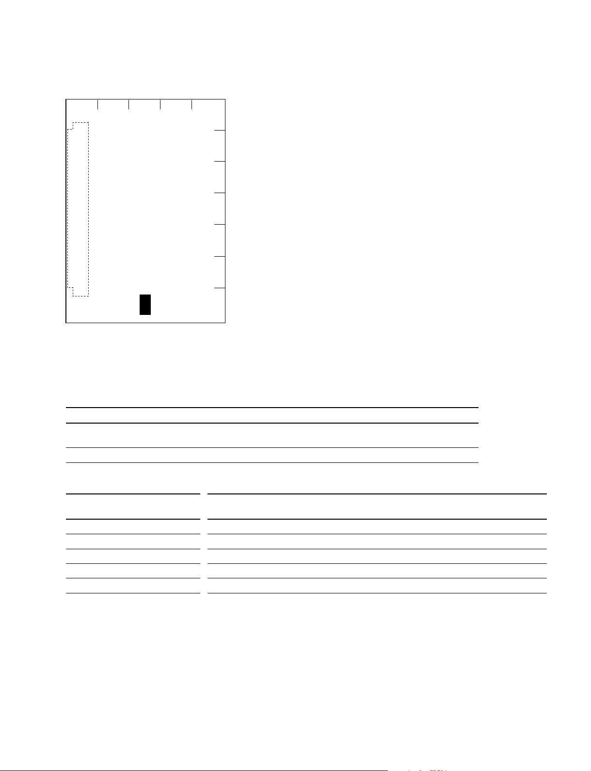
AT-130 board
1-5. Switch Setting on the Boards
1
2345
A
B
C
D
E
F
S100
G
AT-130 board (B side)
n
Never change the setting of the factory use switches.
The state of the factory setting is different with models.
Switch No. Designation Description Factory setting
S100 1 to 4 SETUP MENU Setup menu to be displayed on the OFF
Select viewfinder can be selected. (See the table below)
S100 5 to 8 —— Factory use —
Switch Settings Setup Menu
**
*
S100-1 S100-2 S100-3 S100-4 USER
**
USER MENU
CUSTOMIZE
OFF OFF OFF OFF Yes Yes Yes Yes Yes Yes Yes
ON OFF OFF OFF Yes Yes Yes Yes Yes No Yes
OFF ON OFF OFF Yes Yes Yes Yes No No Yes
ON ON OFF OFF Yes Yes Yes No No No Yes
OFF OFF ON OFF Yes Yes Yes No No No No
* : These menus are displayed only when the ROM version on the AT board of the unit is Ver 1.30 or higher.
**
*
**
OPERATION PAINT MAINTENANCE FILE DIAGNOSIS
HDC-900/950 IMM
1-23 (E)
Page 32

1-6. Setting the Utility Out Voltage (HDC-900/910)
1-6. Setting the Utility Out Voltage
(HDC-900/910)
Set the utility out voltage in accordance with the voltage of
peripheral devices when they are connected to the camera.
The setting of the utility out voltage can be made by the
combination of the switches 1 and 2 in the figure.
HDC-900/910 (CE) only
AC100V
PRESET
. When setting to 100 V
100 120 230
12
100 120 230
12
PRESET
AC OUT
AC100V
200VA MAX
VTR DC IN
Voltage indication seal
PRESET
PRESET
PRESET
AC100V
AC120V
AC220V~
PRESET
PRESET
AC230V~
AC240V~
n
When changing the voltage setting, change the voltage
indication seal.
The seal is supplied with this unit.
. When setting to 120 V
100 120 230
12
. When setting to 230 V
Operation of the switch 1 is not required.
100 120 230
12
1-24 (E)
HDC-900/950 IMM
Page 33

1-7. Adjusting the Position of the
Shoulder Pad (HDC-950/930)
The shoulder pad is factory-configured to the more forward position considering the mass of the camera, yet it is
adjustable according to the type of the lens by following
the procedures below.
1. Remove the three screws shown in the figure and take
the shoulder pad out.
2. Remove the two screws to remove the pad spacer.
3. Slide the shoulder pad backward 10 mm and fix it with
the three screws.
Pad spacer
Screws (B3 x 8)
1-7. Adjusting the Position of the Shoulder Pad (HDC-950/930)
Screw (B4 x 20)
Shoulder pat assembly
Screws (B3 x 6)
HDC-900/950 IMM
1-25 (E)
Page 34

1-8. Installing the Incom Panel Assembly to the Camera Backside (HDC-950/930) 1-9. Installing the Battery Adaptor BKP-L551 (HDC-950/930)
1-8. Installing the Incom Panel
Assembly to the Camera Backside
(HDC-950/930)
n
When disconnecting/connecting a flexible card wire, refer
to Section 1-10.
1. Unscrew the four screws to the blank panel to remove
the blank panel.
Screws
Screws
Screws
CN1
Screws
Incom panel assembly
Blank panel
Flexible card wire
1-9. Installing the Battery Adaptor
BKP-L551 (HDC-950/930)
This section describes the method of installing the battery
adaptor to the right from the standard position.
1. Unscrew the four screws of the blank panel to remove
the blank panel.
2. Reattach the blank panel upside down with the four
screws.
3. Install the battery adaptor referring to BKP-L551
installation manual.
n
Use care that attaching the battery adaptor in this way
restricts the operation of the CCU connector.
Screws
Screws
2. Unscrew the four screws to the incom panel assembly
and disconnect the flexible card wire from the connector CN1 of the SW-1017 board, then remove the incom
panel assembly.
3. Pull out the flexible card wire of the backside of the
camera and connect the connector CN1 of the SW1017 board.
4. Exchange the position of the incom panel assembly
and blank panel and install both of them with the
screws.
Flexible card wire
Screws
Screws
CN1
Screws
Incom panel assembly
Blank panel
Screws
Screws
Blank panel
Screws
1-26 (E)
Blank panel
HDC-900/950 IMM
Page 35

1-10. Disconnecting/Reconnecting Flexible Card Wire
1-10. Disconnecting/Reconnecting Flexible Card Wire
m
. Be sure to turn off the power when disconnecting and connecting the flexible card wire. To power off,
be sure to disconnect the cable connected to the DC IN connector or the battery, in addition to turning
off the power switch.
. The holded flexible card wire remarkably shortens the life span. Pay careful attention when handling it.
Disconnecting
m
. Do not pull the flexible card wire before unlocking.
. There are a conductive portion (printed side) and insulation portion (white belt) in the flexible card
wire. Confirm the direction of the flexible card wire before connecting it.
1. Unlock by shifting portion A of the connector in the direction indicated by the arrow, then pull out
the flexible card wire.
Flexible card wire
A
A
Connector
Insulation portion
Reconnecting
m
. Ensure that no stain or dust adheres on the conductive surface of the flexible card wire.
. Ensure that the connector is unlocked.
1. Insert the flexible card wire firmly as far as it will go.
2. Press in the portion A of the connector in the direction indicated by the arrow to lock the connector.
At that time, take care that the flexible card wire is not inclined.
Flexible card wire
A
HDC-900/950 IMM
A
Connector
1-27 (E)
Page 36

1-11. Notes on Use of the RTS Kit
1-11. Notes on Use of the RTS Kit
Connecting the RTS Intercom System Kit BKP-7913
(option) to the INTERCOM 2 connector of HDC-900/910/
950/930 allows the INTERCOM 2 connector to work with
an RTS intercom system, and be connected to up to two
child devices.
When connecting the RTS kit, perform the following
setting.
AU-271 board suffix -12
Set the switches on the DU-104 board referring to Section
1-5.
AU-271 board suffix -13 and higher
Mount the following chip conductor to R271 (B side : A-1)
on the AU-271 board, and Set the switches on the DU-104
board referring to Section 1-5.
Ref.No. Name SONY Part No.
R271 CONDUCTOR, CHIP (1608) 1-216-864-11
1-28 (E)
R271
1
2345
AU-271 board suffix -13 and higher
(B side)
A
B
C
D
E
F
G
HDC-900/950 IMM
Page 37

Section 2
Service Overview
2-1. Cleaning of Connector/Cable
It is recommendable to clean the optical contact portions
mentioned below before connecting this unit to the camera
control unit.
. CCU connector of this unit
. Camera connector of the camera control unit
. Optical/Electrical cable
It is also necessary to clean the optical contact portions
mentioned below before using the HDC-950/930 to the
large lens adaptor CA-905L.
. CA cable of a large lens adaptor
. CCU connector of a large lens adaptor
Follow the procedures below for cleaning.
Tools Required
. Alignment sleeve remover HC-001
(for female connector)
Sony P/N: J-6480-010-A
n
Insert the shorter nose end when removing/installing the
alignment sleeve.
Grasp not the shock absorber portion of the remover but
the handle in use.
Cleaning
Male connector
Clean the tip of the white optical contacts by a cotton swab
moistened with alcohol.
Optical contacts (white)
Female connector
The optical contacts for female connector are in an unexposed state. In cleaning, it is necessary to be exposed by
removing the alignment sleeve in advance. Proceed as
follows.
1. Insert the alignment sleeve remover into the alignment
sleeve in the straight line and turn it clockwise.
Shock absorber portion Handle
Insert the shorter nose end
. Cotton swabs (commercially available)
n
Use the cotton swab with its diameter of around 4 mm.
The cotton swab with its diameter more than 5 mm does
not enough reach to the inner part of the cable, so that
cannot clean the tip of the optical contact.
HDC-900/950 IMM
2-1 (E)
Page 38

2-1. Cleaning of Optical Connector
2. When the turn stops, pull out the remover in the
straight line forcedly.
n
The alignment sleeve can be removed/reinstalled with
the sleeve itself attached to the tip of the remover.
Great care should be taken so as not to lose or damage
the alignment sleeve.
(Alignment sleeve: Sony P/N 9-980-074-01)
Alignment sleeve
3. Clean the tip of the white optical contacts by a cotton
swab moistened with alcohol.
Optical contacts (white)
4. Insert the remover with the alignment sleeve attached
to its tip, and push it until it clicks.
5. Rotate the remover counterclockwise to install the
alignment sleeve, and extract the remover.
2-2 (E)
HDC-900/950 IMM
Page 39

2-2. Cleaning the Vent Portion of the Fan (HDC-950/930 only)
2-2. Cleaning the Vent Portion of the
Fan (HDC-950/930 only)
A part for preventing from dust is attached in the vent
portion of the fan. Clean this component every two or three
months. Clogging may cause the temperature increases
inside the camera and result in a trouble.
. Top Chassis Cover Assembly
. Fan Grill
. Tail Net
Top Chassis Cover Assembly
(A top cushion is stuck on the backside of the assembly for
protecting from dust.)
1. Remove the four screws (precision P2.6 x 5) to
remove the tope chassis assembly.
2. Wash manually the top chassis cover assembly with
neutral detergent and dry in the shade.
Fan Grill
1. Remove the top chassis cover assembly.
2. Remove the four screws (precision P2.6 x 5) to take
out the fan grill holder.
3. Take out the fan grill and remove dust on the fan grills
with a vacuum cleaner.
Tail Net
1. Remove the two screws to remove the tail guard.
2. Take out the tail net and remove dust on the tail net
with a vacuum cleaner.
B3 x 6
Tail net
B3 x 6
Tail guard
Precision
P2.6 x 5
Fan grill holder
Fan grill
Precision
P2.6 x 5
Precision
P2.6 x 5
Top chassis cover assembly
Precision
P2.6 x 5
HDC-900/950 IMM
2-3 (E)
Page 40

2-3. Replacing the Fuse
2-3. Replacing the Fuse
w
The fuse is critical for safely operating. Do exchange with
the fuses authorized by the manufacturer, otherwise a fire
and electric shock may occur.
2-3-1. HDC-900/910
In the power supply portion of the HDC-900/910, fuses for
protecting from the overcurrent are mounted on each
circuit and each block.
When a fuse burns, find out the cause of the overcurrent
and solve it before replacing the fuse.
When replacing, be sure to use the specified fuses below.
Holder’s name Description Part No.
MAIN FUSE (H.B.C.) 4 A/250 V ! 1-576-231-11
LENS FUSE (H.B.C.) 4 A/250 V ! 1-576-231-11
VF FUSE (H.B.C.) 6.3 A/250 V ! 1-576-233-11
CAMERA FUSE (H.B.C.) 4 A/250 V ! 1-576-231-11
OTHERS FUSE (H.B.C.) 2 A/250 V ! 1-576-228-11
2-3-2. HDC-950/930
Fuses for protecting from the overcurrent are mounted in
the HDC-950/930.
When a fuse burns, find out the cause of the overcurrent
and solve it before replacing the fuse.
When replacing, be sure to use the specified fuse below.
Description Part No.
FUSE GLASS 10 A/125 V ! 1-576-048-11
Replacing
1. Remove the fuse holder with a flat blade screwdriver
and replace the fuse.
Replacing
1. Open the side plate. (Refer to Section 1-4.)
2. Remove the fuse holder with a flat blade screwdriver
and replace the fuse.
n
Use care that the fuses to be used differ depending on
the fuse mounting position.
VF
CAMERA
OTHERS
LENS
MAIN
Fuse
Fuse holder
2-4 (E)
Fuse
Fuse holder
HDC-900/950 IMM
Page 41

2-4. Recommended Replacing Parts
2-4-1. HDC-900/910
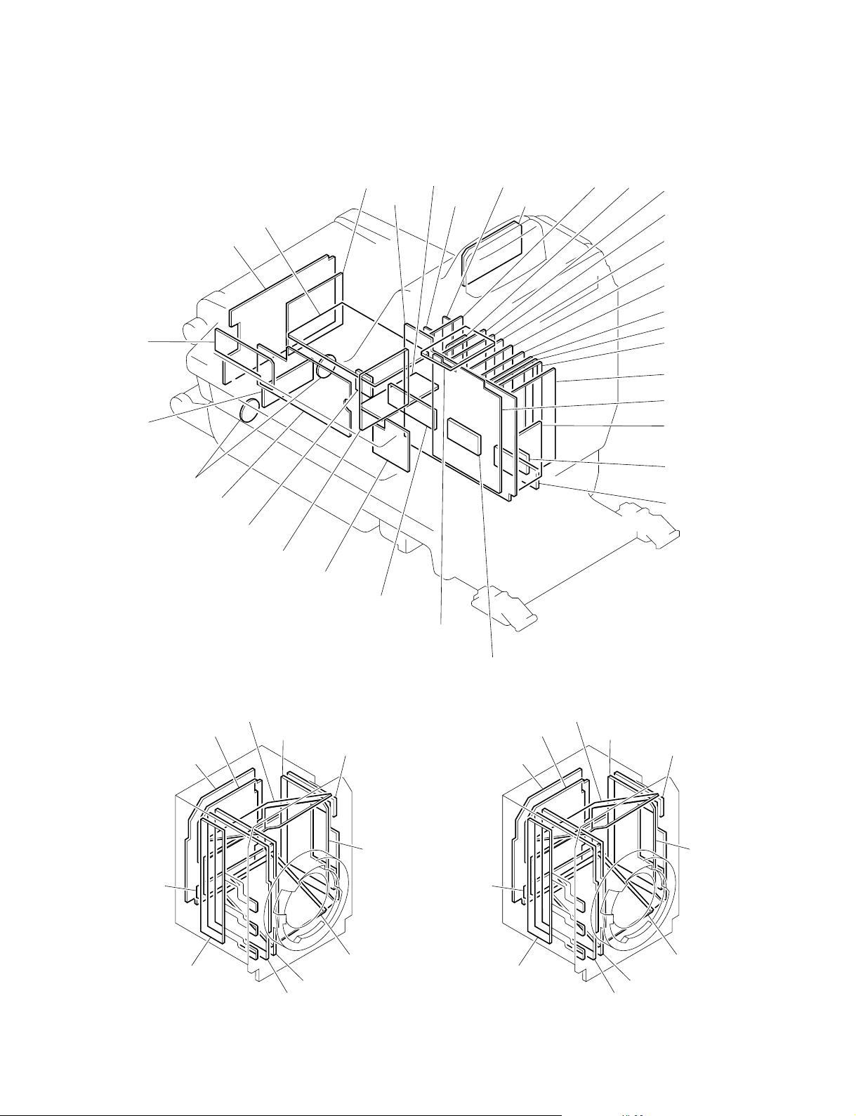
2-4. Recommended Replacing Parts
Following parts are recommended replacing parts. The
optical filter unit may become cloudy with the lapse of
time. By such a cloudy optical filter unit, the characteristics of this camera could not fully exploited, therefore
replace it if necessary.
Besides, the parts made of rubber used for this camera may
become cracked and split with the lapse of time, therefore
also replace it if necessary.
2
1
3
2
1
No. Description Sony Part No.
1 KNOB (DIA 3) ASSY, VOLUME X-3167-563-X
2 KNOB, VOLUME (DIA 6) 3-185-872-0X
3 KNOB, VOLUME 6 3-602-483-0X
4 SHIELD CUSHION (C) 3-615-750-6X
5 BAND, CLAMP 3-612-712-0X
6 PACKING, FAN 3-627-260-0X
7 FILTER UNIT, OPTICAL 1-758-483-11
(HDC-900)
1-758-778-11
(HDC-910)
4
4
1
6
6
4
5
7
HDC-900/950 IMM
2-5 (E)
Page 42

2-4. Recommended Replacing Parts
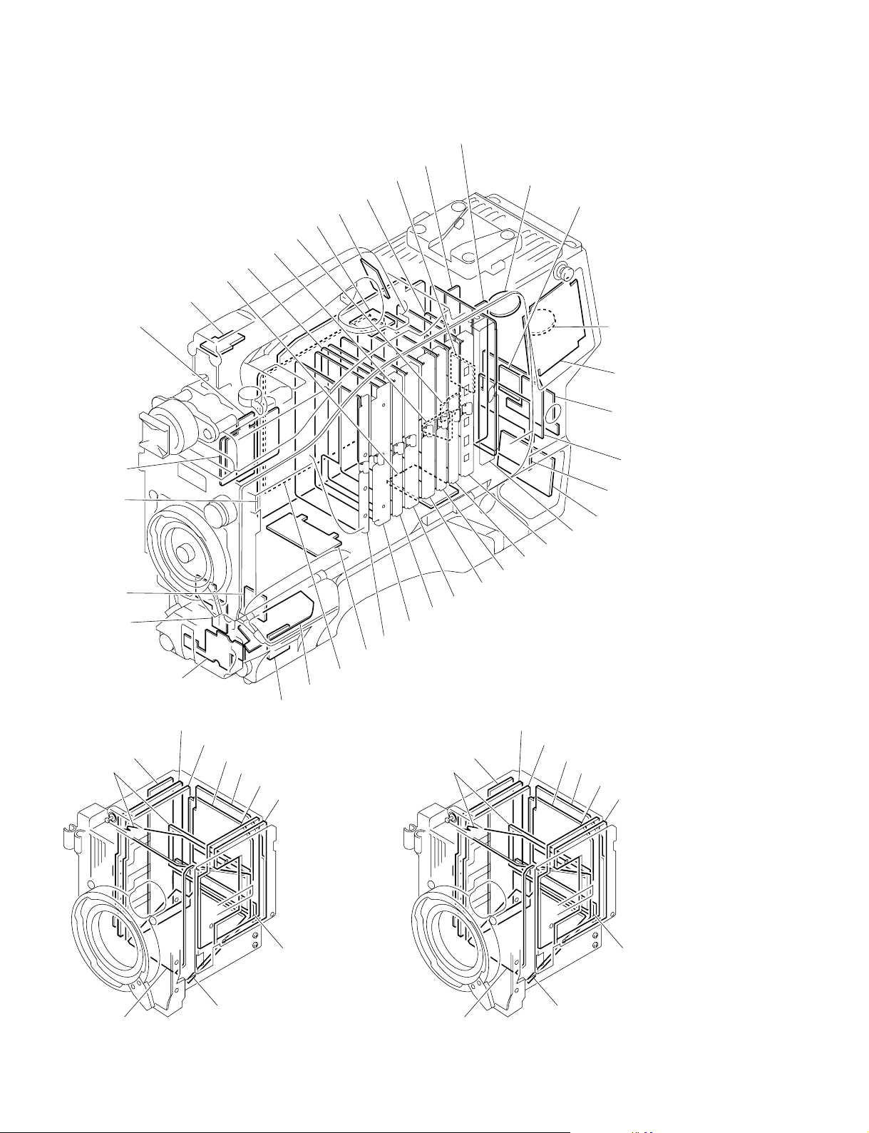
2-4-2. HDC-950/930
Following parts are recommended replacing parts. The
optical filter unit may become cloudy with the lapse of
time. By such a cloudy optical filter unit, the characteristics of this camera could not fully exploited, therefore
replace it if necessary.
Besides, the parts made of rubber used for this camera may
become cracked and split with the lapse of time, therefore
also replace it if necessary.
No. Description Sony Part No.
1 COVER, SWITCH 3-676-244-0X
2 SHEET, HANDLE 3-626-953-0X
3 RUBBER (EA), DROP PROTECTION 3-724-730-0X
4 CHASSIS COVER ASSY, TOP X-3605-899-X
1
2
3
No. Description Sony Part No.
5 CAP, CONNECTOR (CCZ) 3-612-791-0X
6 CAP, TRK 3-626-974-0X
7 CUSHION, FAN 3-627-210-0X
8 BUSHING, RUBBER 3-627-968-0X
9 PAD ASSY, SHOULDER A-8279-359-X
!/ BUTTON, VTR START 3-679-668-0X
!- FILTER UNIT, OPTICAL 1-758-483-11
(HDC-950)
1-758-778-11
(HDC-930)
!= PACKING, VF 3-710-024-0X

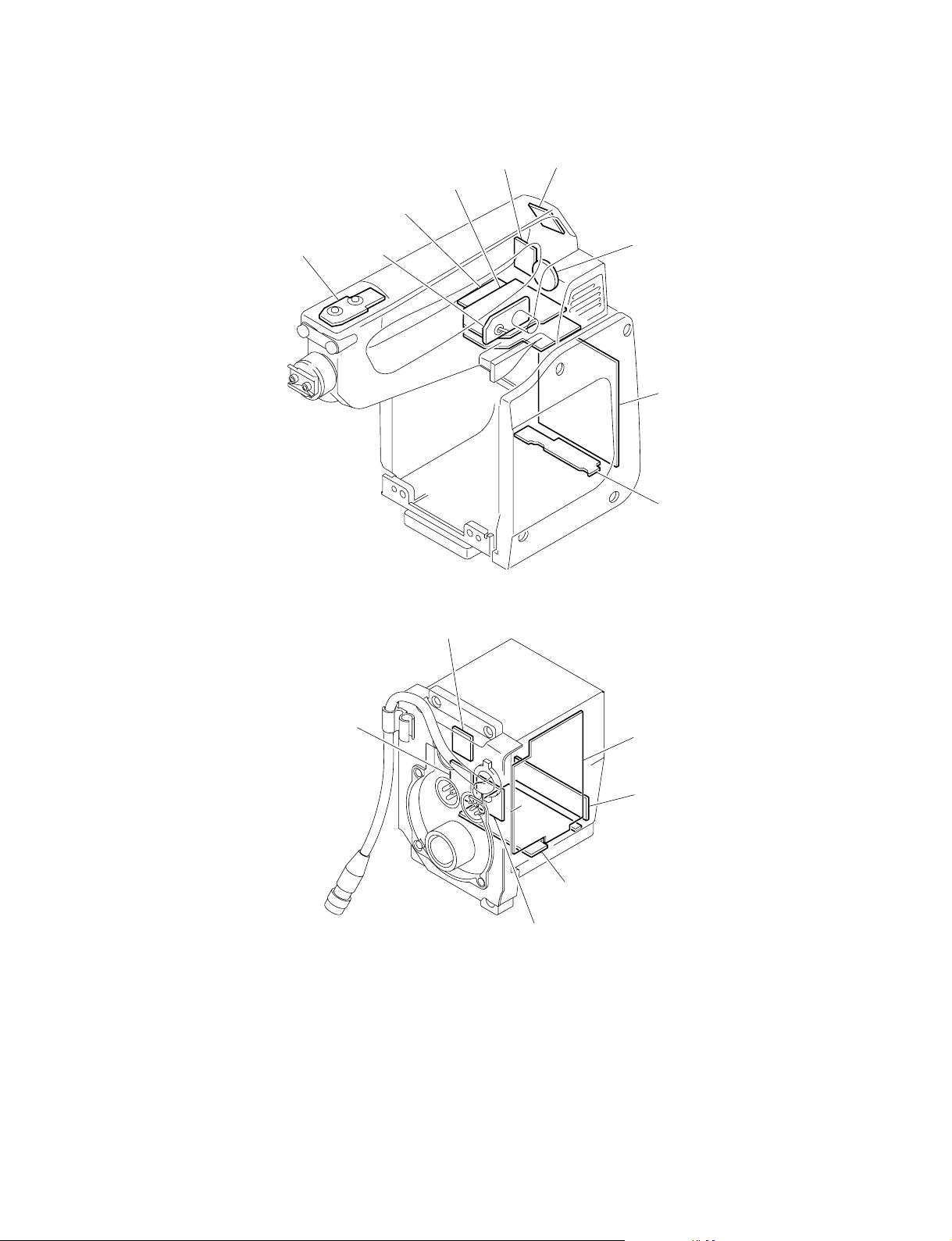
2-4-3. HKC-T950
Following parts are recommended replacing parts.
Besides, the parts made of rubber used for this adaptor may
become cracked and split with the lapse of time, therefore
also replace it if necessary.
No Description Sony Part No.
1 COVER, SWITCH 3-676-244-0X
2 SHEET, HANDLE 3-626-953-0X
3 PACKING, VF 3-710-024-0X
4 CUSHION, FAN 3-627-210-0X
2-4. Recommended Replacing Parts
4
2
1
3
HDC-900/950 IMM
2-7 (E)
Page 44

Page 45

Section 3
Setup Menu
3-1. Setup Menu
The setup menu is used for selecting various setting values, items displayed on the viewfinder screen, the
method of displaying, and adjustments. The menu is displayed on the viewfinder screen. The menu can
also be displayed by connecting an external monitor to the TEST OUT connector.
Structure of Setup Menu
The setup menu is composed of the following menus.
. USER menu (This menu is displayed only when the ROM version on the AT board of the unit is Ver
1.30 or higher.)
. USER MENU CUSTOMIZE menu (This menu is displayed only when the ROM version on the AT
board of the unit is Ver 1.30 or higher.)
. OPERATION menu
. PAINT menu
. MAINTENANCE menu
. FILE menu
. DIAGNOSIS menu
[Reference][Reference]
[Reference]
[Reference][Reference]
Beside above menus, the TOP menu is provided for indicating the whole configuration of the menu items.
Selecting the Menu
The menus to be displayed on the viewfinder screen can be selected by the switches on the AT-130 board
(S100-1 to S100-4). This unit is set to display all menu at the factory setting.
( ) : Shows the factory setting
Switch Settings Setup Menu
S100-1 S100-2 S100-3 S100-4 USER USER MENU OPERATION PAINT MAINTENANCE FILE DIAGNOSIS
(OFF) (OFF) (OFF) (OFF) Yes Yes Yes Yes Yes Yes Yes
ON OFF OFF OFF Yes Yes Yes Yes Yes No Yes
OFF ON OFF OFF Yes Yes Yes Yes No No Yes
ON ON OFF OFF Yes Yes Yes No No No Yes
OFF OFF ON OFF Yes Yes Yes No No No No
CUSTOMIZE
Equipment Required
HDC-900/910
7-type viewfinder HDVF-700A/7700/C700W (or black-and-white monitor)
Camera control unit HDCU-900/700A
HDC-950/930
2-type viewfinder HDVF-20A (or black-and-white monitor)
Camera control unit HDCU-900/950/700A, or AC adapter AC-550, etc. for supplying the power to the
camera.
HDC-900/950 IMM
3-1 (E)
Page 46

3-1. Setup Menu
Switches (HDC-900/910)
DISPLAY switch
ON : Displays characters and messages indicating the
settings and operating status of the unit on the
viewfinder screen.
OFF : Turns off all the displays on the viewfinder
screen.
MENU: Displays the setup menu on the viewfinder screen.
MENU SELECT control
Selects the items displayed on the viewfinder screen and
changes settings.
MENU SELECT switch
ENTER : Determines the menu and item selected by the
MENU SELECT control, and determines the
setting values.
CANCEL : Cancels the menu setting mode and returns to
the page selection mode or TOP menu.
DISPLAY switch
MENU SELECT control
MENU SELECT switch
Basic Operations (HDC-900/910)
1. Displaying the menu
To display the OPERATION menu, turn the power on and set the DISPLAY switch to “MENU”.
To display the other menus, set the DISPLAY switch from “OFF” to “MENU” while pressing the
MENU SELECT switch toward the “ENTER” side, and obtain the TOP menu screen. Turning the
MENU SELECT control, select the menu to be displayed, and press the MENU SELECT switch
toward the “ENTER” side.
2. To change pages, set the cursor to the page number and turn the MENU SELECT control.
3. To shift the cursor, turn the MENU SELECT control. (Pressing the MENU SELECT switch toward
the “ENTER” side determins the setting.)
4. To change a setting value, set the cursor to the item to be changed and press the MENU SELECT
switch toward the “ENTER” side, then the cursor turns to “?” and the value changes by turning the
MENU SELECT control.
(Turning it fast, the value changes greatly, while turning it slowly, the value changes slightly for fine
adjustment.) To determine the setting, press the MENU SELECT switch toward the “ENTER” side,
and to cancel the change, press the MENU SELECT switch toward the “CANCEL” side.
5. By every set of the MENU SELECT switch to “CANCEL”, the screen returns to the item selection
mode, page selection mode, and then TOP menu
(*2)
.
6. To delete the menu displayed, set the DISPLAY switch to “OFF”.
1
(*1)
(*1) : The display screen at the power on is changeable. For change, refer to MENU RESUME item in
OTHERS 2 Page of the MAINTENANCE menu.
(*2) : The page selection mode is available, only when the basic operation step1 was performed and the
operation started from the TOP menu.
Displaying characters on an external monitor (HDC-900/910)
When you want to display characters including the menu on an external monitor connected to the TEST
OUT conector, proceed as follows.
1. Displaying characters. (including the menu)
While pressing the MENU switch toward the “CANCEL” side, set the DISPLAY switch from “OFF”
to “MENU”.
2. To remove the characters/menu from the external monitor.
While pressing the MENU switch towards the “CANCEL” side, set the DISPLAY switch from
“MENU” to “OFF”.
3-2 (E)
HDC-900/950 IMM
Page 47

Switches (HDC-950/930)
DISPLAY switch
ON : Displays characters and messages indicating the
settings and operating status of the unit on the
viewfinder screen.
OFF : Turns off all the displays on the viewfinder
screen.
MENU: Displays the setup menu on the viewfinder screen.
Rotary Encoder
Selects the items displayed on the viewfinder screen and
changes settings.
MENU switch
STATUS : Allows you to check the current setting.
CANCEL : Cancels the menu setting mode and returns to
the page selection mode or TOP menu.
3-1. Setup Menu
DISPLAY switch
MENU switchRotary Encoder
Basic Operations (HDC-950/930)
1. Displaying the menu
To display the OPERATION menu, turn the power on and set the DISPLAY switch to “MENU”.
(*1)
To display the other menus, set the DISPLAY switch from “OFF” to “MENU” while pressing the
rotary encoder, and obtain the TOP menu screen. Turning the rotary encoder, select the menu to be
displayed, and press the rotary encoder.
2. To change pages, set the cursor to the page number and turn the Rotary encoder.
3. To shift the cursor, turn the Rotary encoder. (Pressing the Rotary encoder determins the setting.)
4. To change a setting value, set the cursor to the item to be changed and press the Rotary encoder, then
the cursor turns to “?” and the value changes by turning the Rotary encoder.
(Turning it fast, the value changes greatly, while turning it slowly, the value changes slightly for fine
adjustment.) To determine the setting, press the Rotary encoder, and to cancel the change, press the
MENU switch toward the “CANCEL” side.
5. By every set of the MENU switch to “CANCEL”, the screen returns to the item selection mode, page
selection mode, and then TOP menu
(*2)
.
6. To delete the menu displayed, set the DISPLAY switch to “OFF”.
(*1) : The display screen at the power on is changeable. For change, refer to MENU RESUME item in
OTHERS 2 Page of the MAINTENANCE menu.
(*2) : The page selection mode is available, only when the basic operation step1 was performed and the
operation started from the TOP menu.
Displaying characters on an external monitor (HDC-950/930)
When you want to display characters including the menu on an external monitor connected to the TEST
OUT conector, proceed as follows.
1. Displaying characters. (including the menu)
While pressing the MENU switch toward the “CANCEL” side, set the DISPLAY switch from “OFF”
to “MENU”.
2. To remove the characters/menu from the external monitor.
While pressing the MENU switch towards the “CANCEL” side, set the DISPLAY switch from
“MENU” to “OFF”.
HDC-900/950 IMM
3-3 (E)
Page 48

3-2. TOP Menu
3-2. TOP Menu
The TOP menu is provided for indicating the whole configuration of the menu items.
Displaying the TOP menu
HDC-900/910 : Set the DISPLAY switch from “OFF” to “MENU” while pressing the MENU SELECT
switch toward the “ENTER” side.
HDC-950/930 : Set the DISPLAY switch from “OFF” to “MENU” while pressing the rotary encoder.
[Reference][Reference]
[Reference]
[Reference][Reference]
To select the menu to be displayed on the viewfinder, switch setting on the AT-130 board is required.
For details, refer to “Selecting the Menu” in Section 3-1.
TOP MENU
<TOP MENU>
USER
USER MENU CUSTOMIZE
OPERATION
PAINT
MAINTENANCE
FILE
DIAGNOSIS
Menu Description
a)
USER
USER MENU CUSTOMIZE
OPERATION This menu consists of VF screen display items to be set by a camera
PAINT This menu consists of general paint operation items such as white.
MAINTENANCE This menu consists of paint items used less frequently such as
FILE This menu is used for performing file operations such as saving the
DIAGNOSIS This menu describes the self-diagnosis and VTR status, etc.
a) These menus are displayed only when the ROM version on the AT board of the unit is Ver 1.30 or higher.
a)
You can select desired pages and items from the OPERATION,
PAINT, MAINTENANCE, FILE and DIAGNOSIS menu pages and set
them on the USER MENU CUSTOMIZE menu.
For details, refer to the operation manual supplied with this unit.
This menu is used for editting menu pages and items to be set on the
USER menu.
For details, refer to the operation manual supplied with this unit.
operation.
For details, refer to the operation manual supplied with this unit.
For details, refer to the operation manual supplied with this unit.
shading adjustment and items required for the maintenance of the
camera such as system change.
reference file.
3-4 (E)
HDC-900/950 IMM
Page 49

3-3. OPERATION Menu
3-3. OPERATION Menu
The OPERATION menu consists of the items that a
camera operator can set when using this camera, such as
VF screen display setting.
For details, refer to the operation manual supplied with this
unit.
VF DISPLAY page
Item Setting Initial values
EX 3S, ON, OFF ON
ZOOM 3S, ON, OFF OFF
FOCUS 3S, ON, OFF OFF
ND 3S, ON, OFF ON
CC 3S, ON, OFF ON
IRIS 3S, ON, OFF ON
WHITE 3S, ON, OFF OFF
D5600K 3S, ON, OFF ON
GAIN 3S, ON, OFF ON
SHUTT 3S, ON, OFF ON
BATT 3S, ON, OFF OFF
RETURN 3S, ON, OFF ON
a)
TALK
MESSAG ALL, AT, WRN, OFF ALL
a) This item is displayed only when the ROM version on the AT board of
the unit is Ver 1.30 or higher.
'!' IND page
Item Setting Initial values
ND ON, OFF 1, 2, 3, 4, 5 ON 1
CC ON, OFF A, B, C, D, E ON B
WHITE ON, OFF P, A, B ON A, B
D5600K ON, OFF ON, OFF ON OFF
GAIN ON, OFF L, M, H ON L
SHUTT ON, OFF ON, OFF ON OFF
FAN ON, OFF AUTO1, ON AUTO1
EXT ON, OFF ON, OFF ON OFF
FORMAT ON, OFF 23.98PsF
a) HDC-900/950 only.
3S, ON, OFF ON
[IND] [NORMAL] [IND] [NORMAL]
AUTO2,
MIN, MAX
a)
a)
,
ON 59.94I
a)
,
a)
60I/59.94I, 50I,
30PsF/29.97PsF
25PsF
24PsF/23.98PsF
MARKER page
Item Setting Initial values
MARKER ON, OFF ON
CENTER
a)
ON, OFF ON
1, 2, 3, 4 1
SAFETY ZONE
a)
ON, OFF ON
80.0, 90.0, 92.5, 95.0 90.0
EFECT ON, OFF OFF
ASPECT MODE
b)
16:9, 15:9, 15:9, 13:9 4:3
4:3, VAR H, VAR V,
1035, VISTA1, VISTA2
a)
MASK
ON, OFF OFF
0 to 100 50
VAR WIDTH
b)
0 to 1920 (VAR H) _
0 to 1080 (VAR V) _
SAFETY
a) b)
ON, OFF ON
80.0, 90.0, 92.5, 95.0 90.0
a) Setting ON/OFF of this item is disabled in HDC-900/910. (“[ON], [OFF]”
is displayed.) To set this item to ON or OFF, use the switch located on
the rear side of HDC-900/910. In addition, when connecting CA-905L to
HDC-950/930, setting ON/OFF of this item is also disabled. (“[ON],
[OFF]” is displayed as well.) To set this item ON or OFF, use the switch
located on the rear side of CA-905L.
b) Setting of this item is disabled when setting VF SCAN switch of HDC-
900/910 to 4:3 or when connecting CA-905L to HDC-950/930 and setting
VF SCAN switch of CA905L to 4:3. (“—” is displayed as well.)
GAIN SW page
Item Setting Initial values
LOW _3, 0, 3, 6, 12 0
MIDDLE _3, 0, 3, 6, 12 6
HIGH _3, 0, 3, 6, 12 12
ZEBRA/VF DTL page
Item Setting Initial values
ZEBRA ON, OFF ON
1, 2, 1 & 2 1
ZEBRA1 58 to 82 % 70 %
ZEBRA2 88 to 112 % 100 %
VF SKIN GATE
VF DTL
a) This item is displayed only when the ROM version on the AT board of
the unit is Ver 1.30 or higher.
b) Setting ON/OFF of this item is disabled in HDC-900/910. (“[ON], [OFF]”
is displayed.) To set this item to ON or OFF, use the switch located on
the rear side of HDC-900/910. In addition, when connecting CA-905L to
HDC-950/930, setting ON/OFF of this item is also disabled. (“[ON],
[OFF]” is displayed as well.) To set this item ON or OFF, use the switch
located on the rear side of CA-905L.
a)
ON, OFF OFF
b)
_99 to 99 0
ON, OFF ON
HDC-900/950 IMM
3-5 (E)
Page 50

3-3. OPERATION Menu
AUTO IRIS page
Item Setting Initial values
WINDOW 1, 2, 3, 4, 5, 6 1
OVERRIDE _99 to 99 0
BATT ALARM page
Item Setting Description
DC IN LITHIUM, DIGITAL, AC ADP
c)
TYPE
OTHERS1, OTHERS2,
AC ADP
BEFORE END
d)
END
c) Setting of this item is disabled in HDC-900/910.
When HKC-T950 is used, select OTHERS1.
d) When HKC-T950 is used, set BEFORE END and END to 13 V.
d)
_
_
OTHERS page
Item Setting Initial values
D5600K ON, OFF OFF
ASSIGNABLE 1 OFF, FAN MAX, OFF
EXTENDER
ASSIGNABLE 2
f)
OFF, FAN MAX OFF
MIC 1 GAIN _60, _50, _40, _30, _20 _60
MIC 2 GAIN _60, _50, _40, _30, _20 _60
LENS VTR S/S
g)
RET2 SW, INCOM1, RET2 SW
INCOM2
CAM VTR S/S
g)
RET2 SW, INCOM1, RET2 SW
INCOM2
ZOOM DISP LEFT, RIGHT LEFT
e) Setting to "EXTENDER" is enabled in HDC-900/910 only.
f) Setting of this item is disabled in HDC-900/910. (“—” is displayed.)
g) This setting is valid only when the camera control unit is connected, yet
in the camera is used alone, setting is disabled. (“—” is displayed.)
e)
OPERATOR FILE page
Item Setting
READ (MS → CAM) *1
WRITE (CAM → MS) *1
PRESET *1
*1 HDC-900/910 :
Execute by pressing the MENU SELECT switch toward the “ENTER”
side.
HDC-950/930 :
Execute by pressing the rotary encoder.
LENS FILE page
Item Setting Initial values
FILE 1 to 16 1
3-6 (E)
HDC-900/950 IMM
Page 51

3-4. PAINT Menu
The PAINT menu contains overall general paint adjustment items, such as white adjustment.
For details, refer to the operation manual supplied with this unit.
SW STATUS page
(Display is initial values.)
<SW STATUS>
FLARE : ON
GAMMA : ON
BLK GAM : OFF
KNEE : ON
WHT CLIP : ON
DETAIL : ON
LVL DEP : ON
SKIN DTL : OFF
MATRIX : OFF
Item Setting Description
FLARE ON, OFF Sets the flare correction circuit to ON or OFF.
GAMMA ON, OFF Sets the gamma correction function to ON or OFF.
BLK GAM ON, OFF Sets the black gamma correction function to ON or OFF.
KNEE ON, OFF Sets the knee correction circuit to ON or OFF.
WHT CLIP ON, OFF Sets the white clip function to ON or OFF.
DETAIL ON, OFF Sets the function for attaching the detail signal for improving the
LVL DEP ON, OFF Sets the level dependence function to ON or OFF.
SKIN DTL ON, OFF Sets the skin detail function to ON or OFF.
MATRIX ON, OFF Sets the linear matrix correction function to ON or OFF.
resolution to ON or OFF.
3-4. PAINT Menu
HDC-900/950 IMM
3-7 (E)
Page 52

3-4. PAINT Menu
VIDEO LEVEL page
(Display is initial values.)
<VIDEO LEVEL>
[R] [G] [B] [M]
WHITE : 0 0 0
BLACK : 0 0 0 0
FLARE : 0 0 0 0
GAMMA : 0 0 0 0
V MOD : 0 0 0 0
FLARE : ON
V MOD : ON
TEST : OFF
Item Setting Description
WHITE _99 to 99 Adjusts the white level of R, G, B.
BLACK _99 to 99 Adjusts the black level of R, G, B and master.
FLARE _99 to 99 Adjusts the flare level of R, G, B and master.
GAMMA _99 to 99 Adjusts the gamma correction curve of the R, G, B and master.
V MOD _99 to 99 Adjusts the V modulation shading of R, G, B and master.
FLARE ON, OFF Sets the flare correction circuit to ON or OFF.
V MOD ON, OFF Sets the V modulation shading to ON or OFF.
TEST OFF, 1, 2 Selects the test signal.
OFF : Provides no test signals.
1 : Provides the test signal of the sawtooth waveform.
2 : Provides the test signal of the saw tooth waveform of digital
output.
3-8 (E)
HDC-900/950 IMM
Page 53

GAMMA page
(Display is initial values.)
<GAMMA>
[R] [G] [B] [M]
LEVEL : 0 0 0 0
COARSE : 0.45
TABLE : STANDARD
: 4
GAMMA : ON
TEST : OFF
Item Setting Description
LEVEL _99 to 99 Adjusts the gamma correction curve of the R, G, B and master.
COARSE 0.35 to 0.90 Sets the correction curve of the master gamma in 0.05 steps.
TABLE STANDARD, Selects the gamma table.
GAMMA ON, OFF Sets the gamma correction function to ON or OFF.
TEST OFF, 1, 2 Selects the test signal
*: This item is displayed only when the ROM version on the AT board of the unit is Ver 1.30 or higher.
User gamma table is the file that the customers make according to their needs. The gamma or knee may be set to the fixed value
forcibly when the file is made. In this case, the both or either of gamma and knee controls shown below become disabled.
*
USER
STANDARD : Select the standard gamma table which comes standard
on the unit.
USER : Selects the user gamma table. (Selectable from 5 files.)
1, 2, 3, 4, 5, 6 When STANDARD is selected:
1: INITIAL GAIN 3.5 (equivalent to ENG camcorder)
2: INITIAL GAIN 4.0 LOW (equivalent to EFP camera)
3: INITIAL GAIN 4.0 HIGH (equivalent to EFP camera)
4: INITIAL GAIN 4.0 (equivalent to SMPT-240M)
5: INITIAL GAIN 4.5 (equivalent to ITU-709)
6: INITIAL GAIN 5.0
OFF : Provides no test signals.
1 : Provides the test signal of the sawtooth waveform.
2 :
Provides the test signal of the sawtooth waveform of digital output.
3-4. PAINT Menu
Gamma
. GAMMA page of the PAINT menu
Item : LEVEL, COARSE, GAMMA
Knee
. KNEE page of the PAINT menu
Item : POINT, SLOPE, KNEE
. External switch
AUTO KNEE (OUTPUT/DCC) switch
HDC-900/950 IMM
3-9 (E)
Page 54

3-4. PAINT Menu
BLK GAMMA page
(Display is initial values.)
<BLK GAMMA>
RGB [R] [G] [B] [M]
LEVEL : 0 0 0 0
RANGE : 4
: OFF
Y
LEVEL : 0
RANGE : 4
: OFF
TEST : OFF
Item Setting Description
RGB LEVEL _99 to 99 Adjusts the black gamma of the R, G, B and master.
RGB RANGE 1, 2, 3, 4 Sets the upper limit of the video level which the RGB black gamma
ON, OFF Sets the RGB black gamma correction function to ON or OFF.
Y LEVEL _99 to 99 Adjusts the Y black gamma to adjust the contrast without changing the
Y Range 1, 2, 3, 4 Sets the upper limit of the video level which the Y black gamma
ON, OFF Sets the Y black gamma correction function to ON or OFF.
TEST OFF, 1, 2 Selects the test signal.
affects.
chroma phase of the dark part.
affects.
OFF : Provides no test signals.
1 : Provides the test signal of the sawtooth waveform.
2 :
Provides the test signal of the sawtooth waveform of digital output.
LOW KEY SAT page (Displays ROM Version lower than 1.30)
(Display is initial values.)
<LOW KEY SAT>
LEVEL : 0
: OFF
Item Setting Description
LEVEL _99 to 99 Sets the saturation of the dark part.
ON, OFF Sets the low key saturation function to ON or OFF.
3-10 (E)
HDC-900/950 IMM
Page 55

SATURATION page (Displays ROM Version 1.30 or higher)
(Display is initial values.)
<SATURATION>
SATURATION : 0
: OFF
LOW KEY SAT: 0
RANGE: LOW
: OFF
TEST : OFF
Item Setting Description
SATURATION
LOW KEY SAT _99 to 99 Sets the saturation of the dark part.
RANGE LOW, L MID, H MID, Sets the upper limit of the video level which the low key saturation
TEST OFF, 1, 2 Selects the test signal.
a) This item is not output from the CHARACTER connector of the CNU-700.
a)
_99 to 99 Sets the saturation.
ON, OFF Sets the saturation function to ON or OFF.
HIGH affects.
ON, OFF Sets the low key saturation function to ON or OFF.
OFF : Provides no test signals.
1 : Provides the test signal of the sawtooth waveform.
2 :
Provides the test signal of the sawtooth waveform of digital output.
3-4. PAINT Menu
HDC-900/950 IMM
3-11 (E)
Page 56

3-4. PAINT Menu
KNEE page
ROM Version lower than 1.30 ROM Version 1.30 or higher
(Display is initial values.)
<KNEE>
[R] [G] [B] [M]
POINT : 0 0 0 0
SLOPE : 0 0 0 0
WHT CLP: 0 0 0 0
KNEE SAT LEVEL 0
KNEE : ON
KNEE SAT: OFF
WHT CLIP: ON
TEST : OFF
Item Setting Description
POINT _99 to 99 Sets the knee point level when the settings of the auto knee function
R/G/B/M of the R, G, B and master are OFF.
SLOPE _99 to 99 Sets the knee slope level when the settings of the auto knee function
R/G/B/M of the R, G, B and master are OFF.
WHT CLP _99 to 99 Sets the white clip level of the R, G, B and master.
R/G/B/M
KNEE SAT LEVEL
a)
_99 to 99 Sets the knee saturation level.
KNEE ON, OFF Sets the knee correction circuit to ON or OFF.
KNEE SAT
a)
ON, OFF Sets the knee saturation function to ON or OFF.
WHT CLIP ON, OFF Sets the white clip function to ON or OFF.
AUTO KNEE
KNEE SAT
b)
b)
ON, OFF Sets the auto knee function to ON or OFF.
_99 to 99 Sets the knee saturation level.
ON, OFF Sets the knee saturation function to ON or OFF.
TEST OFF, 1, 2 Selects the test signal.
OFF : Provides no test signals.
1 : Provides the test signal of the sawtooth waveform.
2 :
Provides the test signal of the sawtooth waveform of digital output.
a) These items are displayed only when the ROM version on the AT board of the unit is lower than Ver 1.30.
b) These items are displayed only when the ROM version on the AT board of the unit is Ver 1.30 or higher.
<KNEE>
[R] [G] [B] [M]
POINT : 0 0 0 0
SLOPE : 0 0 0 0
WHT CLP: 0 0 0 0
KNEE : ON WHT CLIP : ON
AUTO KNEE : OFF
KNEE SAT : 0
: OFF
TEST : OFF
3-12 (E)
HDC-900/950 IMM
Page 57

DETAIL 1 page
(Display is initial values.)
<DETAIL 1>
[M] [WHT][BLK]
LEVEL : 0
LIMITER : 0 0 0
CRISPEN : 0
HV RATIO : 0
FREQ : 0
LVL DEP : 0
DETAIL : ON
LVL DEP : ON
Item Setting Description
LEVEL _99 to 99 Sets the general level of the detail signal.
LIMITER _99 to 99 Sets the level for clipping the excessive detail signal.
M/WHT/BLK
CRISPEN _99 to 99 Sets the level for suppressing the noise components contained in the
detail signal.
HV RATIO _99 to 99 Sets the ratio between H detail signal and V detail signal.
FREQ _99 to 99 Sets the frequency of the H detail signal.
LVL DEP _99 to 99
DETAIL ON, OFF Sets the function for attaching the detail signal for improving the
LVL DEP ON, OFF Sets the level depend function to ON or OFF.
Sets the level for suppressing the detail amount in the dark part.
resolution to ON or OFF.
3-4. PAINT Menu
DETAIL 2 page
(Display is initial values.)
<DETAIL 2>
KNEE APERTURE : 0
: OFF
Item Setting Description
KNEE APERTURE _99 to 99 Sets the knee aperture
ON, OFF Sets the knee aperture
a) This function compensates for decreases by the knee aperture in the detail level at the high luminance level part of the camera subject.
a)
level.
a)
function to ON or OFF.
HDC-900/950 IMM
3-13 (E)
Page 58

3-4. PAINT Menu
SKIN DETAIL page
(Display is initial values.)
<SKIN DETAIL>
SKIN DTL : OFF
SKIN GATE: OFF
CH SW : (ON) OFF OFF
GATE : ON OFF OFF
PHASE : AUTO AUTO AUTO
: 0 0 0
WIDTH : 30 30 30
SAT : -89 -89 -89
LEVEL : 0 0 0
Item Setting Description
SKIN DTL ON, OFF When this setting is ON, the setting [1] of the channel 1 is always set
SKIN GATE
CH SW ON, OFF Sets each channel of the skin detail function to ON or OFF.
GATE ON, OFF Sets each channel of the skin gate function to ON or OFF.
PHASE AUTO
WIDTH 0d to 90d Adjusts the chroma phase width of the skin tone detail function to each
SAT _99 to 99
LEVEL _99 to 99 Sets the skin tone detail amount to each channel.
a) Method of executing AUTO
HDC-900/910 : 1. Set the cursor to the AUTO and press the MENU SELECT switch toward the “ENTER” side, then the square-
HDC-950/930 : 1. Set the cursor to the AUTO and press the rotary encoder, then the square-shaped zebra pattern is displayed on
b) This item is displayed only when the ROM version on the AT board of the unit is lower than Ver 1.30.
[1] [2] [3]
ON. Sets the skin detail function to ON or OFF.
b)
ON, OFF Sets the zebra indication of the skin tone detail portion to ON or OFF.
Channel 1 is fixed to ON.
a)
Set automatically the region of each channel the skin detail function affects.
0d to 359d Sets the center phase of the chroma phase the skin tone detail function
affects to each channel.
channel.
Adjusts the saturation level of the skin tone detail function to each channel.
shaped zebra pattern is displayed on the viewfinder.
2. Set the zebra pattern to the color to be given the effect of the skin tone detail and press the MENU SELECT
switch toward the “ENTER” side. to select the phase.
the viewfinder.
2. Set the zebra pattern to the color to be given the effect of the skin tone detail and press the rotary encoder to
select the phase.
3-14 (E)
HDC-900/950 IMM
Page 59

USER MATRIX page
(Display is initial values.)
<USER MATRIX>
[-R] [-G] [-B]
R : -- 0 0
G : 0 -- 0
B : 0 0 --
MATRIX: OFF
PRESET: ON
: SMPTE-240M
USER MATRIX : OFF
MULTI MATRIX: OFF
Item Setting Description
R-G, R-B, _99 to 99 Sets the linear matrix coefficient for each R-G, R-B, G-R, G-B, B-R,
G-R, G-B, _99 to 99 and B-G.
B-R, B-G, _99 to 99
MATRIX
PRESET
USER MATRIX
MULTI MATRIX
a)
a)
ON, OFF Sets the linear matrix correction function to ON or OFF.
ON, OFF Sets the linear matrix correction coefficient set at factory to ON or
OFF.
(When the MATRIX setting is OFF, this setting is unavailable, “- - -” is
displayed showing invalid.)
SMPTE-240M, Selects the linear matrix correction coefficient set at factory.
ITU-709,
SMPTE-WIDE,
NTSC,
EBU
ITU-609
a)
ON, OFF Sets the linear matrix correction function set by the user to ON or
OFF.
(When the MATRIX setting is OFF, this setting is unavailable, “- - -” is
displayed showing invalid.)
a)
ON, OFF Sets the multi matrix correction function to ON or OFF.
(When the MATRIX setting is OFF, this setting is unavailable, “- - -” is
displayed showing invalid.)
3-4. PAINT Menu
a)
USER MATRIX
(+REFERENCE FILE USER MATRIX)
MULTI MATRIX
(+REFERENCE FILE MULTI MATRIX)
PRESET MATRIX
OHB MATRIX
(+OHB FILE OHB MATRIX)
USER MATRIX : Linear matrix that can change R-G and R-B in the conventional camera.
MULTI MATRIX : Linear matrix that divides the chroma phase width of the linear matrix into 16 segments and can adjust each
individually.
PRESET MATRIX : Addition of the linear matrix value fixed in the standard specification.
OHB MATRIX : Linear (multi) matrix for matching the color between the cameras.
HDC-900/950 IMM
USER MATRIX SW MATRIX SW
+ ++
MULTI MATRIX SW
PRESET MATRIX SW
OHB MATRIX SW
LINEAR MATRIX
CIRCUIT
3-15 (E)
Page 60

3-4. PAINT Menu
MULTI MATRIX page
(Display is initial values.)
<MULTI MATRIX>
PHASE : 0
HUE : 0
SAT : 0
ALL CLEAR
MATRIX : OFF
PRESET : ON
: SMPTE-240M
USER MATRIX : OFF
MULTI MATRIX: OFF
Item Setting Description
PHASE 0, 23, 45, 68, 90, Sets the angle that varies the multi matrix correction function.
113, 135, 158, 180, (sixteen-axis mode)
203, 225, 248, 270,
293, 315, 338
HUE _99 to 99 Adjusts the color phase the multi matrix correction function affects in
SAT _99 to 99 Adjusts the saturation level the multi matrix correction function affects in
ALL CLEAR *1 Clears the HUE and SAT values in each phase to 0.
a)
MATRIX
PRESET
a)
ON, OFF Sets the liner matrix correction function to ON or OFF.
ON, OFF Sets the multi matrix correction coefficient set at the factory to ON or
SMPTE-240M, Selects the multi matrix correction coefficient set at the factory.
ITU-709,
SMPTE-WIDE,
NTSC,
EBU
ITU-609
USER MATRIX
MULTI MATRIX
a)
ON, OFF Sets the multi matrix correction function set by the user to ON or OFF.
a)
ON, OFF Sets the multi matrix correction function to ON or OFF.
every sixteen-axis mode.
every sixteen-axis mode.
(The values in the reference file are not cleared.)
OFF. (When MATRIX setting is OFF, this setting is unavailable, “- - -” is
displayed showing invalid.)
(When MATRIX setting is OFF, this setting is unavailable, “- - -” is
displayed showing invalid.)
(When MATRIX setting is OFF, this setting is unavailable, “- - -” is
displayed showing invalid.)
a)
USER MATRIX
(+REFERENCE FILE USER MATRIX)
MULTI MATRIX
(+REFERENCE FILE MULTI MATRIX)
PRESET MATRIX
OHB MATRIX
(+OHB FILE OHB MATRIX)
USER MATRIX : Linear matrix that can change R-G and R-B in the conventional camera.
MULTI MATRIX : Linear matrix that divides the chroma phase width of the linear matrix into 16 segments and can adjust each
individually.
PRESET MATRIX : Addition of the linear matrix value fixed in the standard specification.
OHB MATRIX : Linear (multi) matrix for matching the color between the cameras.
*1 HDC-900/910 : Execute by pressing the MENU SELECT switch toward the “ENTER” side.
HDC-950/930 : Execute by pressing the rotary encoder.
USER MATRIX SW MATRIX SW
+ ++
MULTI MATRIX SW
PRESET MATRIX SW
OHB MATRIX SW
LINEAR MATRIX
CIRCUIT
3-16 (E)
HDC-900/950 IMM
Page 61

SHUTTER page
(Display is initial values.)
<SHUTTER>
SHUTTER : OFF
: 1/100
ECS FREQ: 30.0Hz
S-EVS : OFF
: 0%
Item Setting Description
SHUTTER ON, OFF Sets the shutter/ECS mode to ON or OFF.
Table below
ECS FREQ Table below
S-EVS ON, OFF Sets the S-EVS mode to ON or OFF.
0 to 100 % Sets the S-EVS. (When the format setting 30PsF, 29.97PsF, 25PsF,
a)
Sets the shutter speed.
(The selectable shutter speed varies with each format.)
b)
Sets the ECS frequency.
(The selectable ECS frequency variable region varies with each format.)
24PsF and 23.98PsF, this setting is unavailable. “- - -” is displayed
showing invalid.)
n
For the HDC-910/930, this setting is “100 %” only.
3-4. PAINT Menu
a) Shutter speed setting
Format Shutter speed
60I/59.94I 1/100, 1/125, 1/250, 1/500, 1/1000, 1/2000
50I 1/60, 1/125, 1/250, 1/500, 1/1000, 1/2000
30PsF/29.97PsF *1/40, 1/50, 1/60, 1/120, 1/125, 1/250, 1/500, 1/1000
*
25PsF
1/33, 1/50, 1/60, 1/100, 1/125, 1/250, 1/500, 1/1000
24PsF/23.98PsF *1/32, 1/48, 1/50, 1/60, 1/96, 1/125, 1/250, 1/500, 1/1000
* : For the HDC-910/930, this setting is unavailable.
b) ECS frequency setting
HDC-900/950 :
Format ECS
60I/59.94I 30.0 to 4300 Hz
50I 25.0 to 4700 Hz
30PsF/29.97PsF 30.0 to 2700 Hz
25PsF 25.0 to 2300 Hz
24PsF/23.98PsF 24.0 to 2200 Hz
HDC-910/930 :
Format ECS
60I/59.94I 60.0 to 4300 Hz
50I 50.0 to 4700 Hz
HDC-900/950 IMM
3-17 (E)
Page 62

3-4. PAINT Menu
SCENE FILE page
<SCENE FILE>
1 2 3 4 5 STORE
STANDARD
READ (MS CAM)
WRITE (CAM MS)
FILE ID:
CAM CODE:
DATE:
Item Setting Description
1, 2, 3, 4, 5 Saves and calls the scene file (the data painted in accordance with the
shooting scene.) (Same as the SCENE FILE page in the FILE menu.)
STORE
STANDARD Returns the current paint adjustment amount and switch settings to the
reference values.
READ (MS → CAM) Reads out five scene files from the memory stick to the memory of camera unit.
WRITE (CAM → MS) Writes five scene files stored in the memory of camera unit to the memory stick.
FILE ID Writes comments to a scene file to be stored to the memory stick.
CAM CODE Only displays the model name of the scene file saved in the memory stick.
DATE Only displays the date when the scene file was created in the memory stick.
HDC-900/910
How to save
1. Set “→” to STORE and press the MENU SELECT switch toward the “ENTER” side, then “STORE
NO?”will blink.
2. Select the file No. (1 to 5) for saving.
(If data is already saved, the data will be replaced with new one.)
How to call
Set “→” to the file No. to be called up and press the MENU SELECT switch toward the “ENTER” side.
During calling up, the number is highlighted, and to cancel the operation, press the MENU SELECT
switch toward the “ENTER” side during the highlighting.
HDC-950/930
How to save
1. Set “→” to STORE and press the rotary encoder, then “STORE NO?”will blink.
2. Select the file No. (1 to 5) for saving.
(If data is already saved, the data will be replaced with new one.)
How to call
Set “→” to the file No. to be called up and press the rotary encoder.
During calling up, the number is highlighted, and to cancel the operation, press the rotary encoder during
the highlighting.
3-18 (E)
HDC-900/950 IMM
Page 63

3-5. MAINTENANCE Menu
This menu consists of paint items used less frequently such as shading adjustment and items required for
the camera maintenance such as system change.
AUTO SETUP page
(Display is initial values.)
<AUTO SETUP>
AUTO BLACK
AUTO WHITE
AUTO LEVEL
TEST : OFF
Item Setting Description
AUTO BLACK *1 Starts the automatic black balance adjustment.
AUTO WHITE *1 Starts the automatic white balance adjustment.
AUTO LEVEL *1 Starts the automatic level adjustment of the camera circuit.
TEST OFF, 1, 2 Selects the test signal.
*1 HDC-900/910 : Execute by pressing the MENU SELECT switch toward the “ENTER” side.
HDC-950/930 : Execute by pressing the rotary encoder.
(Pressing the rotary encoder during the execution, the execution is
canceled.)
(Pressing the rotary encoder during the execution, the execution is
canceled.)
(Pressing the rotary encoder during the execution, the execution is
canceled.)
OFF : No test signal is available.
1 : Provides the test signal of the sawtooth wave.
2 :
Provides the test signal of the sawtooth wave of digital output.
3-5. MAINTENANCE Menu
WHITE SHADING page
(Display is initial values.)
<WHITE SHADING>
[R] [G] [B] [M]
V SAW : 0 0 0
V PARA : 0 0 0
H SAW : 0 0 0
H PARA : 0 0 0
WHITE : 0 0 0
V MOD : 0 0 0 0
V MOD : ON
Item Setting Description
V SAW R/G/B _99 to 99 Adjusts the white shading V SAW correction amount of the R,G,B master.
V PARA R/G/B _99 to 99 Adjusts the white shading V PARA correction amount of R,G,B.
H SAW R/G/B _99 to 99 Adjusts the white shading H SAW correction amount of R,G,B.
H PARA R/G/B _99 to 99 Adjusts the white shading H PARA correction amount of R,G,B.
WHITE R/G/B _99 to 99 Adjusts the white level of R,G,B.
V MOD R/G/B _99 to 99 Adjusts the V modulation shading of R,G,B and master.
V MOD ON, OFF Sets the V modulation shading function to ON of OFF.
HDC-900/950 IMM
3-19 (E)
Page 64

3-5. MAINTENANCE Menu
BLACK SHADING page
(Display is initial values.)
<BLACK SHADING>
[R] [G] [B] [M]
V SAW : 0 0 0
V PARA : 0 0 0
H SAW : 0 0 0
H PARA : 0 0 0
BLK SET: 0 0 0
BLACK : 0 0 0 0
MASTER GAIN : 0dB
Item Setting Description
V SAW R/G/B _99 to 99 Adjusts the black shading V SAW correction amount of the R,G,B master.
V PARA R/G/B _99 to 99 Adjusts the black shading V PARA correction amount of R,G,B.
H SAW R/G/B _99 to 99 Adjusts the black shading H SAW correction amount of R,G,B.
H PARA R/G/B _99 to 99 Adjusts the black shading H PARA correction amount of R,G,B.
BLK SET R/G/B _99 to 99 Adjusts the black set correction amount of R,G,B.
BLACK R/G/B/M _99 to 99 Adjusts the black level of the R,G,B and master.
MASTER GAIN _3, 0, 3, 6, 12 dB Sets the master gain.
OHB MATRIX page
(Display is initial values.)
<OHB MATRIX>
PHASE : 0
HUE : 0
SAT : 0
ALL CLEAR
MATRIX : OFF
OHB MATRIX: OFF
Item Setting Description
PHASE 0, 23, 45, 68, 90, Set the region the OHB matrix correction function affects.
113, 135, 158, 180, (sixteen-axis mode)
203, 225, 248, 270,
293, 315, 338
HUE _99 to 99 Adjusts the color phase the OHB matrix correction function affects in
SAT _99 to 99 Adjusts the saturation level the OHB matrix correction function affects in
ALL CLEAR *1 Clears the HUE and SAT values in each phase to 0.
MATRIX ON, OFF Sets the linear matrix correction function ON or OFF.
OHB MATRIX ON, OFF Sets the OHB matrix correction function ON or OFF.
*1 HDC-900/910 : Execute by pressing the MENU SELECT switch toward the “ENTER” side.
HDC-950/930 : Execute by pressing the rotary encoder.
every sixteen-axis mode.
every sixteen-axis mode.
(The values in the OHB file are not cleared.)
3-20 (E)
HDC-900/950 IMM
Page 65
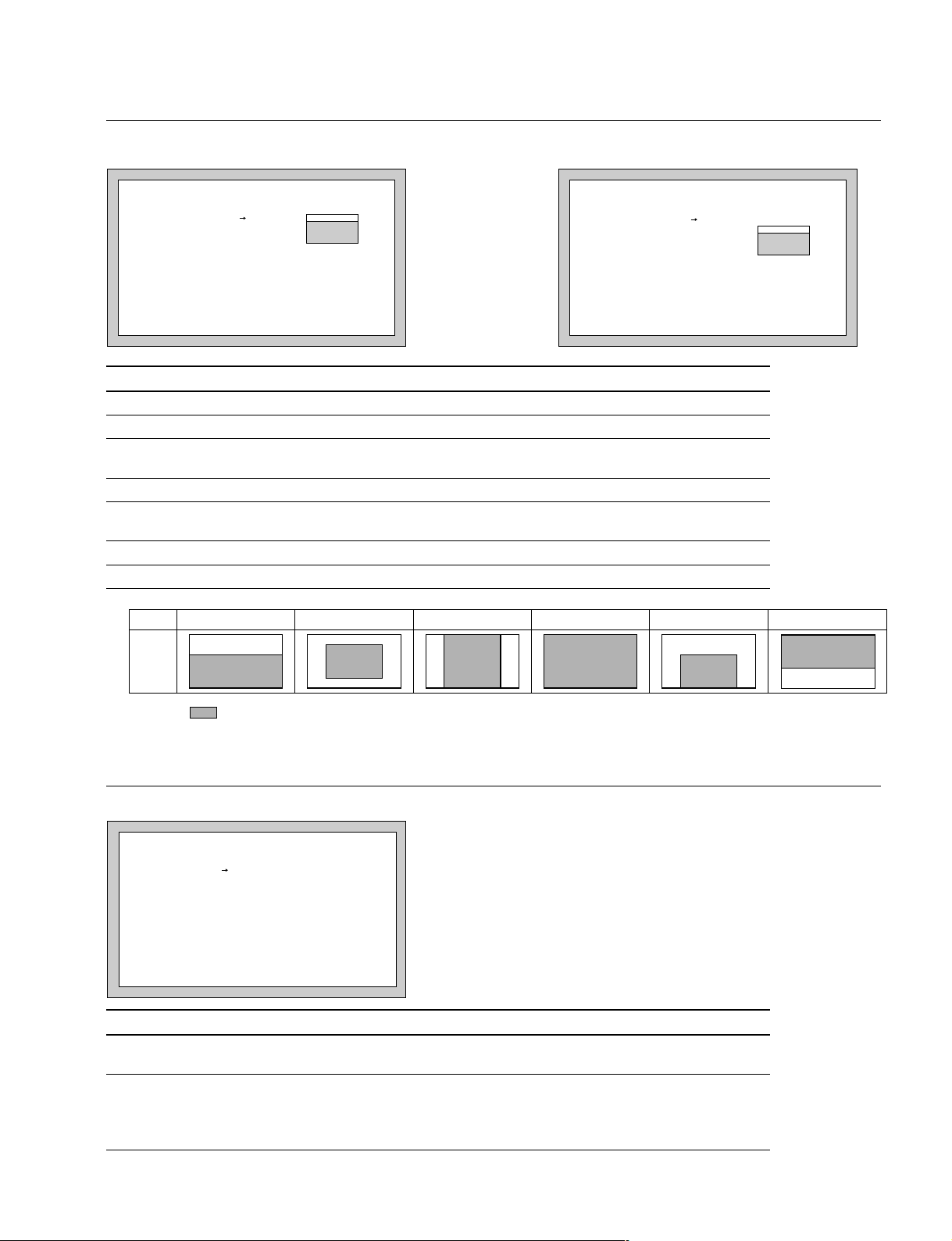
AUTO IRIS page
3-5. MAINTENANCE Menu
ROM Version lower than 1.30 ROM Version 1.30 or higher
(Display is initial values.)
<AUTO IRIS>
WINDOW : 1
OVERRIDE : 0
IRIS LEVEL: 0
APL RATIO : 80
IRIS GAIN : 0
<AUTO IRIS>
AUTO IRIS : OFF
WINDOW : 1
OVERRIDE : 0
IRIS LEVEL: 0
APL RATIO : 80
IRIS GAIN : 0
IRIS CLOSE: OFF
Item Setting Description
AUTO IRIS
WINDOW 1, 2, 3, 4, 5, 6 Selects the auto iris window.
b)
ON, OFF Sets the auto iris function to ON to OFF.
a)
OVERRIDE _99 to 99 Sets the reference value of the auto iris level by ±2 focus.
_99 (2 iris nearly closed) ↔ 99 (2 iris nearly open)
IRIS LEVEL _99 to 99 Sets the auto-iris level.
APL RATIO _99 to 99 Sets the method of detecting the light amount of the auto iris.
_99 (Peak light detection ) ↔ 99 (Average value detection of whole screen)
IRIS GAIN _99 to 99 Sets the iris gain.
IRIS CLOSE
a)
Setting
b)
ON, OFF Sets the iris close function to ON or OFF.
1
56432
VF
screen
indicates the auto iris window frame.
b) These items are displayed only when the ROM version on the AT board of the unit is Ver 1.30 or higher.
CAM ID/DATE page
(Display is initial values.)
<CAM ID/DATE>
CAM ID :
DATE/TIME
2000/04/30 08:32
Item Setting Description
CAM ID Sets the camera ID of less 14 characters consisting of alphanumeric,
DATE/TIME Sets the present date and time.
symbols and spaces.
[Reference][Reference]
[Reference]
[Reference][Reference]
The way of indicating date is changeable.
Refer to DATE TYPE of OTHER2 page in MAINTENANCE menu.
HDC-900/950 IMM
3-21 (E)
Page 66

3-5. MAINTENANCE Menu
MULTI FORMAT page
HDC-900/950 HDC-910/930
(Display is initial values.)
<MULTI FORMAT>
CURRENT 59.94I
NEXT : 59.94I
60I 50I
59.94I
30PsF 25PsF 24PsF
29.97PsF 23.98PsF
Item Setting Description
CURRENT Displays the format being currently selected.
The currently selected format is highlighted in the line below.
a)
NEXT
Selects the format when the power is turned on next time.
HDC-900/910 :
A turn of the MENU SELECT control shifts the portion highlighted.
Press the MENU SELECT switch toward the “ENTER” side for determination. (The highlighted portion does not shift to the *** portion.)
<MULTI FORMAT>
CURRENT 59.94I
NEXT : 59.94I
60I 50I
59.94I
HDC-950/930 :
A turn of the rotary encoder shifts the portion highlighted. Press the
rotary encoder for determination. (The highlighted portion does not shift
to the *** portion.)
a) This setting is valid only when the camera is used alone. When the camera control unit is connected, the camera control unit setting
takes a priority.
SDI page (Displays ROM Version lower than 1.30)
OUT PUT page (Displays ROM Version 1.30 or higher)
ROM Version lower than 1.30 ROM Version 1.30 or higher
(Display is initial values.)
<SDI>
PROMPTER : OFF
BNC SDI OUT: OFF
Item Setting Description
PROMPTER
a)
ON, OFF ON : Prompter signal is output at PROMPTER OUT connector
OFF : No prompter signal is output
BNC SDI OUT
b)
ON, OFF ON : SDI signal is output at HD SERIAL DIGITAL OUT connector
OFF : No SDI signal is output
LINER EXP
c)
ON, OFF ON : Improves the reproducibility of high-luminance part in PsF
format.
OFF : Standard setting.
a) This setting is valid only when the camera control unit is connected, yet in the camera is used alone, setting is disabled. (“—” is
displayed.)
b) This setting is valid only when the camera is used alone. When the camera control unit is connected, setting is always ON. (“—” is
displayed.)
c) This can be selected when the VA-223 board is installed.
<OUT PUT>
PROMPTER : OFF
BNC SDI OUT: OFF
LINER EXP : OFF
3-22 (E)
HDC-900/950 IMM
Page 67

VTR 26PIN page
(Display is initial values.)
<VTR 26PIN>
CABLE COMP: OFF
VIDEO SEL : MAIN(RGB)
MAIN VIDEO ADJUST
G : 0
B : 0
R : 0
Y : 0
Pb : 0
Pr : 0
Item Setting Description
CABLE COMP OFF, 25 m, 50 m Selects the VTR (26P) cable compensation
VIDEO SEL MAIN (RGB), Selects the video signal to be output to the VTR (26 p) OUT connector.
G _30 to 30 Corrects the output level to the VTR (26 P) OUT connector
B _30 to 30 Corrects the output level to the VTR (26 P) OUT connector
R _30 to 30 Corrects the output level to the VTR (26 P) OUT connector
Y _30 to 30 Corrects the output level to the VTR (26 P) OUT connector
Pb _30 to 30 Corrects the output level to the VTR (26 P) OUT connector
Pr _30 to 30 Corrects the output level to the VTR (26 P) OUT connector
a) This setting is valid only when the camera control unit is connected.
MAIN (YPbPr), RET (YPbPr) outputs the return video signal input from the camera
RET (YPbPr)
a)
control unit.
3-5. MAINTENANCE Menu
BATT ALARM page
(Display is initial values.)
<BATT ALARM>
DC IN
TYPE : AC ADP
BEFORE END : - END : --
Item Setting Description
DC IN TYPE
BEFORE END 11.0 to 17.0 V Sets the alarm voltage indicating that the DC power is wearing out.
END 11.0 to 17.0 V Sets the alarm voltage indicating that the DC power has worn out.
a) Setting change of this item is disabled in HDC-900/910.
b) These can be selected when using batteries other than LITHIUM, DIGITA L, AC ADP and the power supply.
c) This can be selected when using an AC/DC power supply of AC-550 and so on.
a)
LITHIUM, DIGITAL, Selects the power running in the DC IN connector.
OTHERS1b), OTHERS2 b),
AC ADP
c)
By this setting, the battery alarm voltage indication in accordance with
the features of the battery or the power supply becomes possible.
When the AC ADP is selected, this setting is unavailable “- - -” is
displayed showing invalid.
When the AC ADP is selected, this setting is unavailable “- - -” is
displayed showing invalid.
HDC-900/950 IMM
3-23 (E)
Page 68

3-5. MAINTENANCE Menu
OTHERS1 page
(Display is initial values.)
<OTHERS 1>
FAN MODE : AUTO1
H PHASE : 0
CHU BARS : OFF
Item Setting Description
FAN MODE AUTO1, Sets the fan mode.
AUTO2, AUTO1 : normal mode
MIN, MAX AUTO2 : silent mode
H PHASE _3072 to 1023 Adjusts the H phase.
CHU BARS ON, OFF Sets the CHU BARS to ON or OFF.
MIN : minimum rotation mode
MAX : maximum rotation mode
3-24 (E)
HDC-900/950 IMM
Page 69

OTHERS2 page
(Display is initial values.)
<OTHERS 2>
MENU RESUME : OPE MENU
DATE TYPE : 1 Y/Mn/D
WHITE MEMORY: 2
COLOR BAR : FULL 16:9
EXT F NO : CONTROL
TRUNK LINE : (1CH)
Item Setting Description
MENU RESUME OPE MENU, Sets the menu screen displayed when starting the menu.
OFF, ALL OPE MENU : Starts to display from the page in the operation menu,
OFF : Starts to display from the first page (VF DISPLAY) in the
ALL : Displays the menu screen, which was displayed at
n
To display the TOP menu, refer to Section 3-2.
DATE TYPE 1 to 6 Sets the date.
1: Y/Mn/D Year/Month/Date (Month should be showed by the figure.)
2: Mn/D Month/Date (Month should be showed by the figure.)
3: D/M/Y Date/Month/Year
4: D/M Date/Month
5: M/D/Y Month/Date/Year
6: M/D Month/Date
WHITE MEMORY 2, 10 Sets the number of white balance memory.
2: White balance memory can be set to A and B of WHITE BAL switch
(total 2).
10:White balance memory can be set to A and B of each CC filter and
WHITE BAL switch (total 8).
COLOR BAR FULL 16 : 9 , Sets the color bar.
SMPTE 16 : 9 , FULL 16 : 9: 100 % color bar of 16 : 9
FULL 4 : 3 , SMPTE 16 : 9: 75 % color bar of 16 : 9
SMPTE 4 : 3 FULL 4 : 3: 100 % color bar of 4 : 3
SMPTE 4 : 3: 75 % color bar of 4 : 3
EXT F NO
a)
CONTROL, Selects the iris indication when the lens extender (x2) to ON.
POSITION CONTROL : Indicated by the control value from the camera.
POSITION : Indicated by the return value from the lens.
TRUNK LINE
a) These items are displayed only when the ROM version on the AT board of the unit is Ver 1.30 or higher.
b) This item is displayed only when the camera control unit is connected.
a) b)
(1CH) Only displays the trunk line mode set by the camera control unit.
which was displayed at powering off of the previous time.
operation menu.
powering off of the previous time.
3-5. MAINTENANCE Menu
HDC-900/950 IMM
3-25 (E)
Page 70

3-5. MAINTENANCE Menu
T ADP ADJ page (Displays ROM Version 1.20 or higher)
(Display is initial values.)
<T ADP ADJ>
[R] [G] [B]
VSAW OFST: -16 -16 -16
CABLE 10M
STORE DATA
Item Setting Description
VSAW OFST _50 ~ +50, - - - Adjusts V SAW correction amount when HKC-T950 is connected.
When HKC-T950 is not connected, this setting is disable, “- - -” is
displayed showing invalid.
CABLE 10M, 25M, 50M Displays the cable length being currently connected.
STORE DATA Execute by pressing Stores the adjustment value to cable adaptor.
the rotary encoder
3-26 (E)
HDC-900/950 IMM
Page 71

3-6. FILE Menu
File menu is used to operate the file such as saving the reference file.
OPERATOR FILE page
<OPERATOR FILE>
READ (MS CAM)
WRITE(CAM MS)
PRESET
STORE PRESET FILE
FILE ID:
CAM CODE
DATE
Item Setting Description
READ *1 Reads the operator file from the memory stick.
(MS → CAM)
WRITE *1 Saves the operator file in the memory stick.
(CAM → MS)
RESET *1 Reset the operator file items to the preset values.
3-6. FILE Menu
STORE PRESET *1 Register the current setting values in the camera unit as the preset
FILE values of the operator file.
FILE ID Writes comments to a file.
CAM CODE Displays the camera name of the file created.
DATE Displays the date when the file was created.
*1 HDC-900/910 : Execute by pressing the MENU SELECT switch toward the “ENTER” side.
HDC-950/930 : Execute by pressing the rotary encoder.
HDC-900/950 IMM
3-27 (E)
Page 72

3-6. FILE Menu
SCENE FILE page
<SCENE FILE>
1 2 3 4 5 STORE
STANDARD
READ (MS CAM)
WRITE (CAM MS)
FILE ID:
CAM CODE
DATE
Item Setting Description
1, 2, 3, 4, 5 Saves and calls the scene file (the data painted in accordance with the
shooting scene.) (Same as the SCENE FILE page in the PAINT menu.)
STORE
STANDARD Returns the current paint adjustment amount and switch settings to the
reference values.
READ (MS → CAM) Reads out five scene files from the memory stick to the memory of camera unit.
WRITE (CAM → MS) Writes five scene files stored in the memory of camera unit to the memory stick.
FILE ID Writes comments to a scene file to be stored to the memory stick.
CAM CODE Only displays the model name of the scene file saved in the memory stick.
DATE Only displays the date when the scene file was created in the memory stick.
HDC-900/910
How to save
1. Set “→” to STORE and press the MENU SELECT switch toward the “ENTER” side, then “STORE
NO?”will blink.
2. Select the file No. (1 to 5) for saving.
(If data is already saved, the data will be replaced with new one.)
How to call
Set “→” to the file No. to be called up and press the MENU SELECT switch toward the “ENTER” side.
During calling up, the number is highlighted, and to cancel the operation, press the MENU SELECT
switch toward the “ENTER” side during the highlighting.
HDC-950/930
How to save
1. Set “→” to STORE and press the rotary encoder, then “STORE NO?”will blink.
2. Select the file No. (1 to 5) for saving.
(If data is already saved, the data will be replaced with new one.)
How to call
Set “→” to the file No. to be called up and press the rotary encoder.
During calling up, the number is highlighted, and to cancel the operation, press the rotary encoder during
the highlighting.
3-28 (E)
HDC-900/950 IMM
Page 73

REFERENCE page
<REFERENCE>
STORE FILE
STANDARD
READ(MS CAM)
WRITE(CAM MS)
FILE ID:
CAM CODE
DATE
Item Setting Description
STORE FILE *1 Registers the adjustment values of each item as the reference file.
STANDARD *1 Returns the data registered in the reference file to the reference value.
READ (MS → CAM) Reads out reference file from the memory stick to the memory of camera unit.
WRITE (CAM → MS) Writes reference file stored in the memory of camera unit to the memory stick.
FILE ID Writes comments to a reference file to be stored to the memory stick.
CAM CODE Only displays the model name of the reference file saved in the memory stick.
DATE Only displays the date when the reference file was created in the memory stick.
*1 HDC-900/910 : Execute by pressing the MENU SELECT switch toward the “ENTER” side.
HDC-950/930 : Execute by pressing the rotary encoder.
3-6. FILE Menu
USER GAMMA page (Displays ROM Version 1.30 or higher)
<USER GAMMA>
READ (MS CAM)
FILE ID:
CAM CODE
DATE
Item Setting Description
READ (MS → CAM) *1 Reads the user gamma file from the memory stick to the memory of the
FILE ID Writes comments to a user gamma file to be stored to the memory stick.
CAM CODE Only displays the model name that created the user gamma file saved in the
DATE Only displays the date when the user gamma file was created in the memory
*1 HDC-900/910 : Execute by pressing the MENU SELECT switch toward the “ENTER” side.
HDC-950/930 : Execute by pressing the rotary encoder.
camcorder.
memory stick.
stick.
HDC-900/950 IMM
3-29 (E)
Page 74

3-6. FILE Menu
LENS FILE page
(Display is initial values.)
<LENS FILE>
STORE FILE
NO. : 1
NAME : HA14x8
F NO : F2.0
CENTER MARKER
H POS: 0
V POS: 0
STORE CENTER
Item Setting Description
STORE FILE *1 Registers the adjustment values for each item (exc. the center marker position)
as the lens file.
No. 1to 16 Selects the file matching with the mounted lens from the sixteen lens files
NAME Displays the lens file name in accordance with the No. (1 to 16) selected.
F NO F1.0 to F3.4 Sets the open edge F value of the lens.
H POS _20 to 20 Sets the center marker position (Horizontal)
V POS _20 to 20 Sets the center marker position (Vertical)
STORE CENTER *1 Registers the center marker position in the lens file being selected.
*1 HDC-900/910 : Execute by pressing the MENU SELECT switch toward the “ENTER” side.
HDC-950/930 : Execute by pressing the rotary encoder.
20 (right) ↔ _20 (left)
20 (lower) ↔ _20 (upper)
OHB FILE page
<OHB FILE>
STORE FILE
Item Setting Description
STORE FILE *1 Stores the OHB file.
*1 HDC-900/910 : Execute by pressing the MENU SELECT switch toward the “ENTER” side.
HDC-950/930 : Execute by pressing the rotary encoder.
3-30 (E)
HDC-900/950 IMM
Page 75

FILE CLEAR page
(Display is initial values.)
<FILE CLEAR>
PRESET OPERATOR
REFERENCE(ALL)
10 SEC CLEAR: OFF
LENS(CURRENT)
OHB WHITE SHAD
OHB BLACK SHAD
OHB ND OFFSET
OHB MATIX
MS FORMAT
Item Setting Description
PRESET *1 Returns the preset value of the operator file set by the user to the
OPERATOR original value at factory setting.
REFERENCE (ALL) *1 Returns each adjustment value registered in the reference file to the
10 SEC CLEAR ON, OFF HDC-900/910 :
LENS (CURRENT) *1 Returns the lens file being selected to the original value at factory
OHB WHITE SHAD Clears the white shading in the OHB file to 0.
OHB BLACK SHAD Clears the black shading in the OHB file to 0.
OHB ND OFFSET Clears the ND offset in the OHB file to 0.
OHB MATRIX Clears the matrix in the OHB file to 0.
MS FORMAT Formats the memory stick.
*1 HDC-900/910 : Execute by pressing the MENU SELECT switch toward the “ENTER” side.
HDC-950/930 : Execute by pressing the rotary encoder.
original values at factory setting.
Sets ON or OFF the function to clear the reference value by continuing
to push the MENU SELECT switch toward the “ENTER” side for more
than ten seconds with the cursor set to the reference item and “?”
blinking.
HDC-950/930 :
Sets ON or OFF the function to clear the reference value by continuing
to push the rotary encoder for more than ten seconds with the cursor
set to the reference item and “?” blinking.
n
The setting returns to OFF when the unit is powered off.
setting.
3-6. FILE Menu
HDC-900/950 IMM
3-31 (E)
Page 76

3-7. DIAGNOSIS Menu
3-7. DIAGNOSIS Menu
The DIAGNOSIS menu displays the self-diagnosis of every plug-in board and photo-receptive condition
of the optical connector, etc.
SDI page
<SDI>
OPTICAL LEVEL:GREEN
Item Setting Description
OPTICAL LEVEL GREEN, Displays a photo-receptive condition of the optical connector
YELLOW, GREEN : Normal (_17 dBm * or more)
RED, YELLOW : Normal (_17 to _20 dBm *)
NO SIGNAL RED : Abnormal (less than _20 dBm *)
___ NO SIGNAL : Out of sync with HDCU
___ : When the camera is used alone
*
0 dBm = 1 mW
n
If “RED” is indicated, be sure to clean the optical connector and optical/electrical cable. If “YELLOW” is
indicated, cleaning them is recommended. For details on how to clean, refer to Section 2-1.
3-32 (E)
HDC-900/950 IMM
Page 77

BOARD STATUS page
<BOARD STATUS>
ROM:V1.00
OHB :OK SG :OK
VA :OK AT :OK
DPR :OK AU :OK
VDA :OK RE :OK
DAD :OK PS :OK
SDI :OK
DAP :OK
Item Setting Description
ROM Indicates the ROM version for IC1/AT-130 board
OHB OK, NG Displays the self-diagnosis status of the CCD block.
VA OK, NG Displays the self-diagnosis status of the VA board.
DPR OK, NG Displays the self-diagnosis status of the DPR board.
VDA OK, NG Displays the self-diagnosis status of the VDA board.
DAD OK, NG Displays the self-diagnosis status of the DAD board.
SDI OK, NG Displays the self-diagnosis status of the SDI board.
DAP OK, NG Displays the self-diagnosis status of the DAP board.
SG OK, NG Displays the self-diagnosis status of the SG board.
AT OK, NG Displays the self-diagnosis status of the AT board.
AU OK, NG Displays the self-diagnosis status of the AU board.
RE OK, NG Displays the self-diagnosis status of the RE board.
a)
PS
a) This setting is valid only when the camera control unit is connected, yet in the camera is used alone, setting is disabled. (“—” is
displayed.)
b) When HKC-T950 is connected, it judges based on status of the connection cable, communication state between the CCD block
adaptor and cable adaptor and so on in addition to the diagnosis in the camera that is being used alone.
OK, NG Displays the self-diagnosis status of the PS board.
b)
3-7. DIAGNOSIS Menu
n
When “NG” is indicated, contact your local Sony Sales Office.
HDC-900/950 IMM
3-33 (E)
Page 78

Page 79

Section 4
g
File System
The HDC-900/910/950/930 are equipped with various file systems for managing data.
4-1. File Structure
The following six types of files are available.
1. Operator File
Stores the items displayed on the viewfinder and switch settings for camera operator. This file is
stored in the memory stick, yet the video data (paint data) cannot be stored.
2. Preset Operator File
Stores the standard state of operator file items.
This file is stored in the camera, yet video data (paint data) cannot be stored.
3. Scene File
Stores the temporary video setting data according to the scene. This file is stored in the camera and
memory stick.
4. Reference File
Stores the custom paint data adjusted by the video engineer. This file is stored in the camera and
memory stick.
5. Lens File
Used for compensation of the deviation which generates by switching the lens extender from OFF to
ON and for compensation of the difference in the characteristics between lenses. This file is stored in
the camera.
6. OHB File
Used for adjustment of the CCD block maintenance. This file is stored in the camera.
Scene File
Refer to Section 4-8. “File Items”.
When STANDARD
is executed
Factory-set value 0
When lens extender setting is OFF, Flare R/G/B and
V Modulation Shading R/G/B/Master can be stored.
When lens extender setting is ON, White R/B, Flare R/G/B and
V Modulation Shading R/G/B/Master can be stored.
Refer to Section 4-8. “File Items”.
R/G/B for each White Shading H SAW, H PARA, V SAW, VPARA can be stored.
R/G/B for each Black Shading H SAW, H PARA, V SAW, V PARA can be stored.
And OHB matrix and the ND offset can be stored.
Fi
. 4-1. Structure of Paint Related Files
Lens File
Reference File
OHB File
(*1): The additional data of each file is sent to each circuit on the unit.
Output to
hardware
(*1)
HDC-900/950 IMM
4-1 (E)
Page 80

4-2. Operator File
4-2. Operator File
Data is stored in the memory stick using the setup menu. As for the items to be stored, refer to Section 48,“ File Items”.
m
. As for the setup menu, refer to Section 3.
. Operator files stored in the memory stick will not be read when the power is just turned ON. This file
will only be read when READ is executed at the setup menu.
. The current operator file data is retained even when the power is turned off by the power switch.
. Before storing the file in the memory stick, make sure that the LOCK switch on the memory stick is in
OFF position.
Storing the Operator File in the Memory Stick (Refer to step 1 of Fig. 4-2.)
Set the setup menu as follows, and store the current status in the memory stick.
Reading the Operator File from the Memory Stick (Refer to step 2 of Fig. 4-2.)
Set the setup menu as follows.
Memory stick
Reading
(Step 2)
Current Operator
File Data
Output to hardware
Storing
(Step 1)
Camera unit
Preset
reading
(Step 3)
Preset Operator File
Preset
storing
(Step 4)
Fig. 4-2. Operating Procedure for Operator Files
Preset
initialization
(Step 5)
Preset factory-set
value
4-2 (E)
HDC-900/950 IMM
Page 81

4-3. Preset Operator File
The preset operator file is designed to store the standard values of the operator file items. There are two
ways of calling the preset operator file; calling from the setup menu or reading at power ON. The items
which can be stored on file are the same as Operator File.
n
As for the setup menu, refer to Section 3.
Calling Using the Setup Menu (Refer to step 3 of Fig. 4-2.)
Set the setup menu as follows.
[OPERATION] → [OPERATOR|FILE] → [PRESET]
Calling without Using the Setup Menu (Refer to step 3 of Fig. 4-2.) (For HDC-950/930)
Set the WHITE BAL switch to “PRST”, and while pushing the AUTO W/B BAL switch to the WHT
side, set the POWER switch to ON.
4-3. Preset Operator File
Storing the Preset Values (Refer to step 4 of Fig. 4-2.)
The items of the preset values can be changed using the setup menu.
Set the setup menu as follows.
[FILE] → [OPERATOR|FILE] → [STORE|PRESET|FILE]
Then, current status can be stored in the camera as Preset Operator File.
Initializing the Preset Values (Refer to step 5 of Fig. 4-2.)
Set the setup menu as follows to initialize the changed preset items to the factory-set data.
[FILE] → [FILE|CLEAR] → [PRESET|OPERATOR]
HDC-900/950 IMM
4-3 (E)
Page 82

4-4. Registering the Scene File
4-4. Registering the Scene File
The scene file is used for storing temporary video adjustment values according to the scene. 5 files can be
stored and the data will be stored in the camera and memory stick. The data can be stored using a setting
menu or MSU (master setup unit).
Scene files can be copied between cameras using the memory stick.
As for the items to be stored, refer to Section 4-8,“ File Items”.
m
. Scene files are files for storing the differences from the reference file. Therefore when the reference file
is changed, output of the scene file item corresponding with the item changed in the reference file is
also changed.
. As for the setup menu, refer to Section 3.
. Before storing the file in the memory stick, make sure that the LOCK switch on the memory stick is in
OFF position.
Storing Using Setup Menu (Refer to step 1 of Fig.4-3.)
(1) Set the setup menu as follows.
[PAINT] → [SCENE|FILE] → [STANDARD]
(2) Change the scene file item to the desired value.
(3) Set the setup menu as follows.
[PAINT] → [SCENE|FILE] → [STORE]
Select the scene file number to be stored.
Calling Using Setup Menu and Clearing the Call (Refer to step 2 of Fig.4-3.)
Select the scene file number called at the “SCENE FILE” page of the PAINT menu. A file currently being
called is shown with its file No. highlighted. Selecting the number again clears the call and resets the state
before calling.
Storing with MSU (Refer to step 1 of Fig.4-3.)
(1) Change the scene file item to the desired value.
(2) Press “STORE” of the scene file, and press the STORE number.
Calling with MSU and Clearing the Call (Refer to step 2 of Fig.4-3.)
Press the No. switch of the “SCENE FILE” to call. The switch also lights up. Press again to cancel the
call and turn off the switch.
4-4 (E)
HDC-900/950 IMM
Page 83

4-4. Registering the Scene File
Storing the Scene File to the Memory Stick (Refer to step 1 of Fig. 4-3.)
The scene file stored in the camera unit is stored to the memory stick.
Set the setup menu as follows.
Reading the Scene File from the Memory Stick (Refer to step 3 of Fig. 4-3.)
The scene files stored in the memory stick are read to the memory of camera unit.
Set the setup menu as follows.
n
When the power is just turned on, the reference files stored in the memory stick will not be read. This file
will only be read when READ is executed at the setup menu.
Camera unit
Current paint data
Output to hardware
Storing
(Step 1)
Scene File
Calling
(Step 2)
Fig. 4-3. Operating Procedure for Scene Files
Storing in
memory stick
(Step 1)
Memory stick
Readng from
memory stick
(Step 3)
HDC-900/950 IMM
4-5 (E)
Page 84

4-5. Registering Reference Files
4-5. Registering Reference Files
This file can be stored and read using the setup menu or MSU (master setup unit). Only one file can be
stored, and will be stored in the camera and memory stick.
As for the items to be stored, refer to Section 4-8,“ File Items”.
For reference files, differential data taking the factory-setting as 0 will be stored. Therefore, initializing
the reference file brings the settings to the same status at factory-setting.
items or specified items can be initialized.
Reference files can be copied between cameras using the memory stick.
(*1) : If lens files or OHB file retains the data, those need to be initialized as well.
m
. As for the setup menu, refer to Section 3.
. Before storing the file in the memory stick, make sure that the LOCK switch on the memory stick is in
OFF position.
Storing Using the Setup Menu (Refer to step 1 of Fig.4-4.)
(*1)
Using the setting menu, all
Set the setup menu as follows.
[FILE] → [REFERENCE] → [STORE|FILE]
The data will be stored in the camera and the numerical data will be displayed as 0. (Excluding some
items. Refer to Section 4-8. “File Items”.)
Storing by MSU (Refer to step 1 of Fig.4-4.)
Set the MODE switch to FILE and press [REFERENCE] and then press [REF|STORE]. The data will
be stored in the camera and the numerical data will be displayed as 0. (Excluding some items. Refer to
Section 4-8. “File Items”.)
Calling Using the Setup Menu (Refer to step 2 of Fig. 4-4, Fig. 4-1.)
Set the setup menu as follows.
[PAINT] → [SCENE|FILE] → [STANDARD]
The temporary paint amount and scene file amount will be cleared and the reference file will be reset to
the state stored in.
Calling with MSU (Refer to step 2 of Fig. 4-4.)
Press the “STANDARD” switch to reset the reference file item to the state stored in.
4-6 (E)
HDC-900/950 IMM
Page 85

4-5. Registering Reference Files
Reading the Reference File from the Memory Stick (Refer to step 3 of Fig. 4-4.)
During the file storing, the reference files which have been stored in the memory stick at the same time
are read and the reference files in the camera can also be changed.
Set the setup menu as follows.
After the data of the memory stick is read to the camera, STANDARD will be executed automatically.
n
When the power is just turned on, the reference files stored in the memory stick will not be read. This file
will only be read when READ is executed at the setup menu.
Storing the Reference File to the Memory Stick (Refer to step 1 of Fig. 4-4.)
The reference file stored to the camera unit is stored in the memory stick.
Set the setup menu as follows.
Initializing All File Items Using the Setup Menu (Refer to step 4 of Fig. 4-4.)
Set the setup menu as follows.
HDC-900/950 IMM
4-7 (E)
Page 86

4-5. Registering Reference Files
Initializing Only Specified Items Using the Setup Menu (Refer to step 4 of Fig. 4-4.)
References files for specified items can be initialized using the setup menu.
(1) Set the setup menu as follows.
[FILE] → [FILE|CLEAR] → [10|SEC|CLEAR] → [ON]
(2) Move to the page containing the items to be initialized from the reference files in the setup menu.
(3) HDC-900/910
Adjust “→” to the item to be initialized using the MENU SELECT control, and keep pressing the
MENU SELECT switch toward the ENTER side about 10 seconds at “?” state until “REF CLEAR “
is displayed. About 3 seconds later, “DATA CLEAR” will be displayed at the bottom most line. The
“REF CLEAR” is displayed about 10 seconds later, and the data will be initialized to 0.
HDC-950/930
Adjust “→” to the item to be initialized using the rotary encoder, and keep pressing the rotary
encoder about 10 seconds at “?” state until “REF CLEAR “ is displayed. About 3 seconds later,
“DATA CLEAR” will be displayed at the bottom most line. The “REF CLEAR” is displayed about
10 seconds later, and the data will be initialized to 0.
n
The 10 SEC CLEAR function must always be set to OFF when the power is turned ON.
Camera unit
Current paint data
Output to hardware
Memory stick
Storing in
memory stick
(Step 1)
Storing
(Step 1)
Reference File
Calling
(Step 2)
Fig. 4-4. Operating Procedure for Reference Files
Readng from
memory stick
(Step 3)
Initialization
(Step 4)
Reference File
factory-set value
(Initial value 0)
4-8 (E)
HDC-900/950 IMM
Page 87

4-6. Registering the Lens File
4-6. Registering the Lens File
The white shading which occurs when the extender is turned on, flare balance, white balance, F value of
the open edge of the lens, name, etc. can be stored. Up to 16 files can be stored. The adjustment data can
be called by selecting the lens file. This data will be stored in the camera.
As for the items to be stored, refer to Section 4-8,“ File Items”.
The lens file stores the differential data from the reference file.
m
. Prior to creating the lens file, perform the necessary adjustments by using the lens normally used to
create the reference file.
. As for the setup menu, refer to Section 3.
Adjusting the Lens File
(1) Mount the lens. Select the file with the same name of the lens mounted from the setup menu.
If no file with the same lens name, select “NO OFFSET”.
[FILE] → [LENS|FILE] → [No.] → (Select the No.)
(2) Set the lens file name and F value of the open edge of the lens.
(3) With the lens extender set to OFF, adjust V modulation of R/G/B/Master. Shoot the all white pattern,
set the iris F4 and zoom position to the center of the ring, and perform the adjustment around 560 mV
of 80% video level. Also adjust the flare balance and white balance shooting the grayscale chart.
(4) Store the data in the lens file. Set the setting menus as follows.
[FILE] → [LENS|FILE] → [STORE|FILE]
(5) Set the extender to ON, adjust the V modulation of R/G/B/Master shooting the all white pattern, and
adjust the flare balance and white balance shooting the grayscale chart.
(6) Store the data in the lens file.
(7) If the lens center deviates when the lens extender is switched to ON/OFF, store the center marker
under the extender is ON state. Adjust [CENTER|H|POS] and [CENTER|V|POS] at the
[LENS|FILE] page, and execute [STORE|CENTER].
n
The center marker will not be stored when the lens file is stored.
Calling the Lens File
Select the lens file set by the setup menu as follows.
[OPERATION] → [LENS|FILE]
Initializing the Lens File
Set the setup menu as follows.
All data of the lens file being currently selected will be initialized to the factory setting values.
HDC-900/950 IMM
4-9 (E)
Page 88

4-7. Registering the OHB File
4-7. Registering the OHB File
The OHB file is used for storing the maintenance adjustment values of the CCD block and the data will
be stored in the camera. The data can be stored using the setup menu or the MSU (master setup unit).
The items to be stored are the black shading, white shading, ND offset and OHB matrix.
n
As for the setup menu, refer to Section 3.
4-7-1. Storing the Black Shading and White Shading
Storing Using the Setup Menu
(1) Execute the setup menu as follows.
[FILE] → [REFERENCE] → [STANDARD]
(2) Change the items to the desired value; H SAW, H PARA, V SAW and V PARA of each R/G/B for
each of white shading and black shading.
(3) Set the setup menu as follows.
[FILE] → [OHB|FILE] → [STORE|FILE]
Storing with MSU
(1) Change the items to the desired value; H SAW, H PARA, V SAW, V PARA of each R/G/B for each
of white shading and black shading.
(2) Press “STORE” of the OHB file.
4-10 (E)
HDC-900/950 IMM
Page 89

4-7. Registering the OHB File
4-7-2. Adjusting the ND Offset
The white balance may be slightly deviated in the ND filters. In such cases, adjust the offset. Taking the
ND filter 1 white balance as the reference, the ND offset stores the deviation of the white balance of ND
filter 2, 3, 4.
Adjusting the ND Offset
(1) Set the setup menu as follows.
[FILE] → [REFERENCE] → [STANDARD]
(2) Connect the waveform monitor to MONITOR OUT connector of this unit.
(3) Select ND filter 4, and shoot the grayscale chart. Check that the illuminant condition is under that
video level is within 560 mV thru. 630 mV. Then note the video level at this time.
n
Do not adjust the ND offset if the video level is less than 560 mV.
(4) Select 1 by the ND filter knob, and set the iris so that the video level is the same level as the noted
video level of Step (2).
(5) Execute the auto white balance.
(6) Select 2 by the ND filter knob, and set the iris to meet the noted video level of Step (2).
(7) Execute the auto white balance.
(8) Select 3 by the ND filter knob, and set the iris to meet the noted video level of Step (2).
(9) Execute the auto white balance.
(10) Select 4 by the ND filter knob, and set the iris to meet the noted video level of Step (2).
(11) Execute the auto white balance.
(12) Store the ND offset.
Execute the setup menu as follows.
[FILE] → [OHB] → [STORE|FILE]
m
. Adjust precisely to meet the noted video level, otherwise the deviation of the white balance of the ND
filter may generate in some cases.
. If the level cannot be adjusted properly using the iris, adjust the level using the shutter/ECS or gain-up.
Calling the ND Offset
When the ND filter is changed, the ND offset will be called automatically.
Initializing the ND Offset
Execute the setup menu as follows.
[FILE] → [FILE|CLEAR] → [OHB|ND|OFFSET]
HDC-900/950 IMM
4-11 (E)
Page 90

4-8. File items
4-8. File items
OPERATION menu
page item OPERATOR REFERENCE SCENE OHB LENS STANDARD
(*9)
Power is Factory
turned ON set
1 VF DISPLAY _____ _(*2)
2 ! IND _____ _(*2)
3 MARKER _____ _(*2)
4 GAIN SW L/M/H _____ _0/6/12 dB
5 ZEBRA _____ _(*2)
VF DETAIL _____ _0
6 AUTO IRIS WINDOW _____ _1
(*8)
OVERRIDE __ ____ _0
7 BATT ALARM _____ _(*2)
8 D5600K _ __ REF _ OFF
ASSIGNABLE 1/2 _____ _OFF
MIC 1 GAIN O_ ____ __60 dB
MIC 2 GAIN O_ ____ __60 dB
LENS VTR S/S O_ ____ _RET2
CAM VTR S/S O_ ____ _RET2
ZOOM DISP O_ ____ _LEFT
9 LENS FILE NO. __ ____ _1
PAINT menu
(*7)
(*9)
Power is Factory
turned ON set
_ 0
STANDARD4
page item OPERATOR REFERENCE SCENE OHB LENS STANDARD
2 WHITE R/B _O O_O
(*4)
REF
WHITE G _OO__REF _ 0
BLACK R/G/B __ O__0 _ 0
BLACK MASTER _OO__REF _ 0
FLARE R/G/B _O O_OREF _ 0
FLARE SW _ ON __ ON _ ON
V MOD R/G/B __ O___ _0
V MOD MASTER __ O_O_ _0
V MOD SW _ ON ___ ON _ ON
3 GAMMA R/G/B _OO__REF _ 0
GAMMA MASTER _O O__REF _ 0
GAMMA COARSE _ __ REF _ 0.45
GAMMA TABLE _ __ REF _
GAMMA SW _ ON __ ON _ ON
4 BLK GAMMA R/G/B _OO__REF _ 0
BLK GAMMA MASTER _O O__REF _ 0
BLK GAMMA RGB RANGE
_ __ REF _ 4
BLK GAMMA RGB SW _ __ REF _ OFF
BLK GAMMA Y _OO__REF _ 0
4-12 (E)
HDC-900/950 IMM
Page 91

4-8. File items
page item OPERATOR REFERENCE SCENE OHB LENS STANDARD
(*9)
Power is Factory
turned ON set
4 BLK GAMMA Y RANGE _ __ REF _ 4
BLK GAMMA Y SW _ __ REF _ OFF
5 LOW KEY SAT _OO__REF _ 0
LOW KEY SAT SW _ __ REF _ OFF
SATURATION SW _ __ REF _ OFF
SATURATION LEVEL _OO__REF _ 0
LOW KEY SAT RANGE _ __ REF _ LOW
6 KNEE POINT R/G/B _OO__REF _ 0
KNEE POINT MASTER _OO__REF _ 0
KNEE SLOPE R/G/B _OO__REF _ 0
KNEE SLOPE MASTER _O O__REF _ 0
KNEE SW _ __ REF _ ON
AUTO KNEE SW _ __ REF _ OFF
ADAP KNEE SW _ __ REF _ OFF
WHITE CLIP R/G/B _OO__REF _ 0
WHITE CLIP MASTER _OO__REF _ 0
WHITE CLIP SW _ ON __ REF ON ON
KNEE SAT LEVEL _O O__REF _ 0
KNEE SAT SW _ __ REF _ OFF
7 DETAIL LEVEL _OO__REF _ 0
DETAIL SW _ ON __ REF _ ON
DETAIL WHITE LIMITER _OO__REF _ 0
DETAIL BLACK LIMITER _OO__REF _ 0
DETAIL LIMITER MASTER
_OO__REF _ 0
DETAIL CRISPEN _O O__REF _ 0
DETAIL H/V RATIO _OO__REF _ 0
DETAIL H FREQ _O O__REF _ 0
DETAIL LEVEL DEPEND _OO__REF _ 0
DETAIL LEVEL DEP SW _ __ REF _ ON
8 KNEE APERTURE _OO__REF _ 0
KNEE APT SW _ __ REF _ OFF
9 SKIN DETAIL LEVEL _OO__REF _ 0
SKIN DETAIL PHASE 1/2/3
SKIN DETAIL WIDTH 1/2/3
_ __ REF _ 0d
_ __ REF _ 30d
SKIN DETAIL SAT 1/2/3 _ __ REF __89
SKIN DETAIL CH_1 SW _ ON __ ON _ ON
SKIN DETAIL CH_2,3 SW _ __ REF _ OFF
SKIN DETAIL GATE SW __ ____ OFF OFF
SKIN DETAIL GATE 1 SW _ ON
SKIN DETAIL GATE 2/3 SW
_ OFF
(*1)
(*1)
___ ON _ ON
___ OFF _ OFF
10 USER MATRIX _ __ REF _ 0
USER MATRIX SW _ __ REF _ OFF
PRESET MATRIX SEL _ __ REF _ SMPTE-240M
HDC-900/950 IMM
4-13 (E)
Page 92

4-8. File items
page item OPERATOR REFERENCE SCENE OHB LENS STANDARD
(*9)
Power is Factory
turned ON set
10 PRESET MATRIX SW _ __ REF _ OFF
MATRIX SW _ __ REF _ OFF
11 MULTI MATRIX PHASE __ ____ _0
MULTI MATRIX HUE _ __ REF _ 0
MULTI MATRIX SAT _ __ REF _ 0
MULTI MATRIX SW _ __ REF _ OFF
12 SHUTTER SEL _ __ REF _
SHUTTER SW __ __ _ _
(*5)
(*5)
1/100
OFF
ECS SW _ __ REF _ OFF
ECS FREQ _ __ REF _ 30.0 Hz
S_EVS (%) _ __ REF _ 0
S_EVS SW _ __ REF _ OFF
TEST 1 __ ____ _OFF
TEST 2 __ ____ _OFF
MAINTENANCE menu
page item OPERATOR REFERENCE SCENE OHB LENS STANDARD
2 WHITE SHADING __ _O_OHB _ 0
VSAW R/G/B
WHITE SHADING __ _O_OHB _ 0
VPARA R/G/B
WHITE SHADING __ _O_OHB _ 0
HSAW R/G/B
WHITE SHADING __ _O_OHB _ 0
HPARA R/G/B
3 BLACK SHADING __ _O_OHB _ 0
VSAW R/G/B
BLACK SHADING __ _O_OHB _ 0
VPARA R/G/B
BLACK SHADING __ _O_OHB _ 0
HSAW R/G/B
BLACK SHADING __ _O_OHB _ 0
HPARA R/G/B
BLACK SET R/G/B __ ____ _0
MASTER GAIN _ __ REF _
4
OHB MULTI MATRIX PHASE
OHB MULTI MATRIX HUE
OHB MULTI MATRIX SAT
__ ____ _0
__ _O_OHB _ 0
__ _O_OHB _ 0
OHB MATRIX SW __ ____ _OFF
5 AUTO IRIS SW __ __ _ ON
AUTO IRIS LEVEL _ __ REF _ 0
AUTO IRIS APL RATIO _ ___ REF _ 80
AUTO IRIS GAIN _ ___ REF _ 0
IRIS CLOSE SW __ ____ OFF
6 CAMERA ID __ ____ __
4-14 (E)
(*9)
Power is Factory
turned ON set
(*5)
(*3)
(*3)
0 dB
ON
OFF
HDC-900/950 IMM
Page 93

4-8. File items
page item OPERATOR REFERENCE SCENE OHB LENS STANDARD
(*9)
Power is Factory
turned ON set
7 MULTI FORMAT __ ____ _59.94 I
8 PROMPTOR __ ____ _OFF
BNC SDI OUT __ ____ _OFF
LINER EXP __ ____ _OFF
9 VTR 26P CABLE COMP __ ____ _OFF
VTR 26P MAIN VIDEO ADJ
__ ____ _0
VTR 26P VIDEO SEL __ ____ _YPbPr
10 BATT ALARM __ ____ _(*2)
11 FAN MODE _ __ REF _ AUTO1
H PHASE __ ____ _0
CHU BARS __ ____ _OFF
12 MENU RESUME __ ____ _OPE MENU
DATE TYPE __ ____ _Y/Mn/D
WHITE MEMORY __ ____ _10
COLOR BAR __ ____ _FULL 16 : 9
EXT F NO __ ____ _CONTROL
TRUNK LINE __ ____ _(1CH)
13 VSAW OFST R/G/B
(*10)
__ _(*11) __ _10 m : _8
25 m : _16
50 m : _32
TEST 1 __ ____ _OFF
TEST 2 __ ____ _OFF
FILE menu
page item OPERATOR REFERENCE SCENE OHB LENS STANDARD
a)
4
LENS FILE NAME __ __ __1
LENS FILE IRIS F NO. __ __ __F2.0
LENS FILE CENTER __ __ __0
MARKER H
LENS FILE CENTER __ __ __0
MARKER V
a)
6
REFERENCE 10 SEC __ ____ OFF OFF
CLEAR
a) These pages are different by the ROM version on the AT board of the unit.
(*9)
Power is Factory
turned ON set
External switches
item OPERATOR REFERENCE SCENE OHB LENS STANDARD
ND FILTER __ __ _ _ ND1
ND OFFSET __ _O__ _0
CC FILTER __ __ _ _ CCB
AUTO KNEE (DCC) _ __ REF _
CHU COLOR BAR __ ____ _
WHITE MEMORY PRESET A, B __ ____ _
(*9)
Power is Factory
turned ON set
(*5)
(*5)
(*6)
OFF
OFF
B
HDC-900/950 IMM
4-15 (E)
Page 94

4-8. File items
MSU connected only
item OPERATOR REFERENCE SCENE OHB LENS STANDARD
V DTL CREATION MODE _ __ REF _ Y
V DTL CONTROL MODE _ ___ REF _ H/V
KNEE MAX _ OFF __ OFF OFF OFF
AUTO KNEE POINT _ ___ REF _ 0
WHITE SETUP MODE __ ____ _AWB
(*9)
Power is Factory
turned ON set
shows an analog item which will not be indicated as 0 after being stored.
O shows an analog item which will be indicated as 0 after being stored.
shows a switch which will be stored in the select item.
REF returns the status to the one when stored in the reference file.
OHB returns the status to the one when stored in the OHB file.
If mentioned as ON or OFF, the values will be same as ON or OFF.
If mentioned as _, the value does not change.
(*1): In SKIN DETAIL GATE 1/2/3, one among 1, 2 and 3 is to be set ON.
(*2): Refer to Section 4,“ Setup Menu”.
(*3): Only when using standalone
(*4): WHITE value stored is used when the extender ON.
(*5): The state depends on the one of the external switch when the standalone state.
(*6): When connecting to the MSU (master setup unit), the memory enters the temporally released state. As PRESET
brings WHITE R/G/B to 0, regardless of the factory setting value of 3200K, if changing WHITE R/G/B and performing REFERENCE STORE, the specified value is recalled as PRESET.
(*7): When WHITE SETUP MODE setting is ABW, the value when selecting AWB is returned and when selecting
AUTO LEVEL, 0 is returned.
(*8):
Setting
1
56432
VF
screen
indicates the auto iris window frame.
(*9): Shows items to be called when [STANDARD] is executed, that is the reference file is called.
(*10): These items can be set only when HKC-T950 is connected.
(*11): Saved in the cable adaptor of HKC-T950.
4-16 (E)
HDC-900/950 IMM
Page 95

The material contained in this manual consists of
information that is the property of Sony Corporation.
Sony Corporation expressly prohibits the duplication of
any portion of this manual or the use thereof for any
purpose other than the operation or maintenance of the
equipment described in this manual without the express
written permission of Sony Corporation.
Le matériel contenu dans ce manuel consiste en
informations qui sont la propriété de Sony Corporation.
Sony Corporation interdit formellement la copie de
quelque partie que ce soit de ce manuel ou son emploi
pour tout autre but que des opérations ou entretiens de
l’équipement à moins d’une per mission écrite de Sony
Corporation.
Das in dieser Anleitung enthaltene Material besteht aus
Informationen, die Eigentum der Sony Corporation sind.
Die Sony Corporation untersagt ausdrücklich die
Vervielfältigung jeglicher Teile dieser Anleitung oder den
Gebrauch derselben für irgendeinen anderen Zweck als
die Bedienung oder Wartung der in dieser Anleitung
beschriebenen Ausrüstung ohne ausdrückliche
schriftliche Erlaubnis der Sony Corporation.
HDC-900/950 IMM
Page 96

HKC-T950 (SY)
HDC-900 (SY)
HDC-900/L (J)
HDC-910 (UCJ, CE)
HDC-910/L (J)
HDC-930 (SY)
HDC-950 (JN, SY) J, E
3-204-338-08
Printed in Japan
Sony Corporation 2003. 10 08
B&P Company ©2000
 Loading...