

Page 1
www.sonybiz.net/anycast
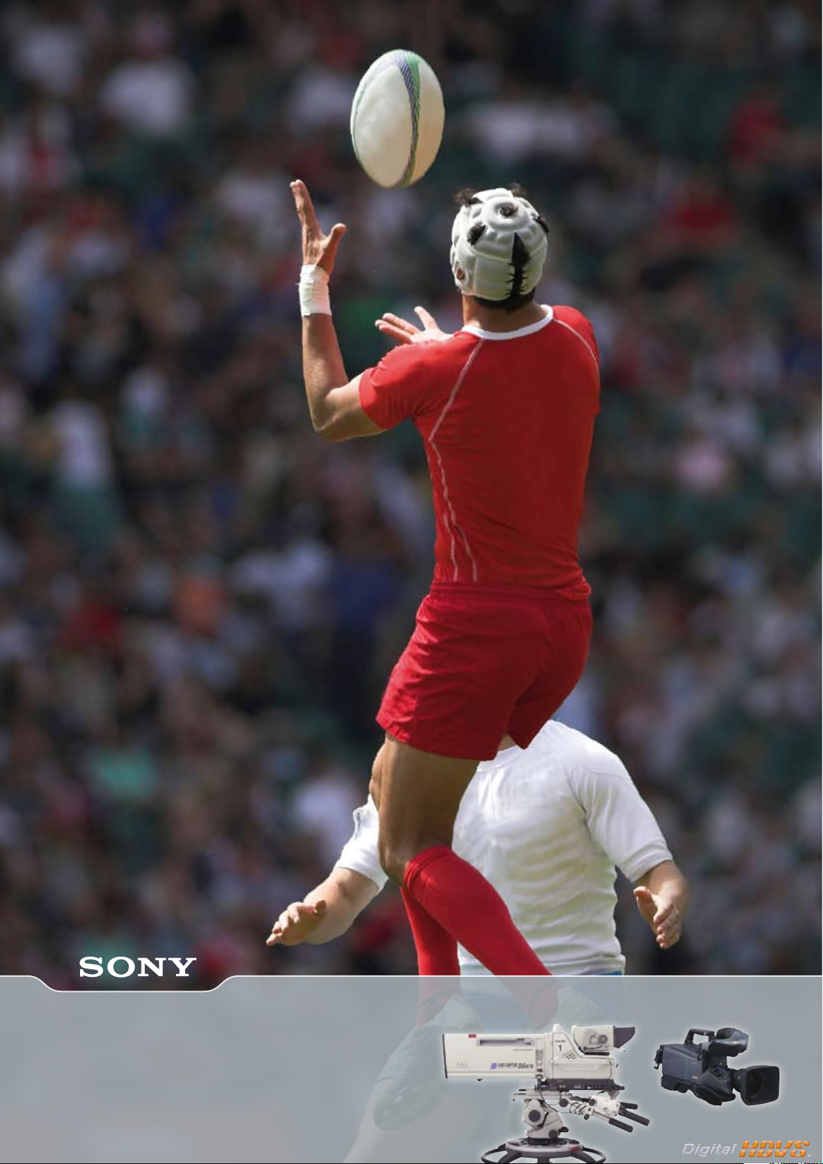
HDC-1000 Series
World-class HD Camera System
Page 2
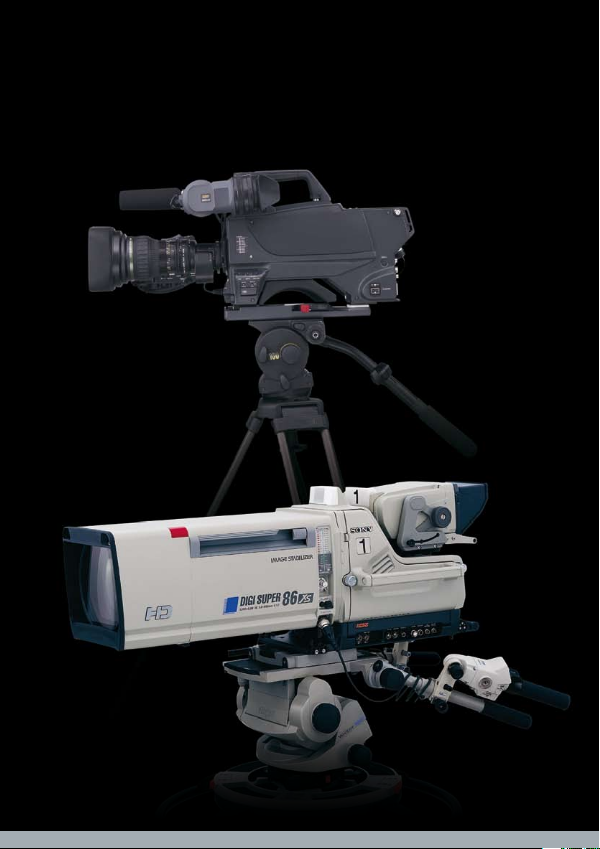
HDC-1500
HDC-1000
Sony HDC-1000 Series
A Family of HD Production Tools
Page 3
A major reason for this popularity is the wide
range of system parts which allow customers
to configure an HD camera system for
almost any application they require. These
parts include a selection of viewfinders, two
Camera Control Units, six Remote Control
Panels as well as comprehensive connectivity and control options and interfaces for
Hybrid Fibre and Triax cabling. The innovative Large Lens and CRT adapters allow a
portable camera to be docked with Studio
peripherals almost instantly. No re-cabling
or adjustment is required thanks to the camera ‘hot-shoe’ electrical interface and
lens registration features.
No less important is the ability to capture
superb images in all world wide standards,
both progressive and interlaced, in 1080 or
720 formats and at multiple frame rates.
The amazing picture quality achieved
by this new camera system is due to the
development of an improved CCD and a
completely new Digital Signal Processing
LSI. The CCD is capable of capturing full HD
resolution (1080 x 1920) images at up 60
progressive frames per second in the normal
camera and 180 interlaced frames per
second in the unique, 3 x slow motion
camera. The DSP in turn allows the camera
operator unparalleled freedom of control
over the ‘look’ of the images without
unwanted side effects. New user functions
include multi matrix and variable black
gamma.
Sony HDC cameras are manufactured in our
dedicated factory in Pencoed – South Wales, to the
highest environmental standards.
Please see
http://www.sony.net/SonyInfo/Environment/activities/index.html
for more information
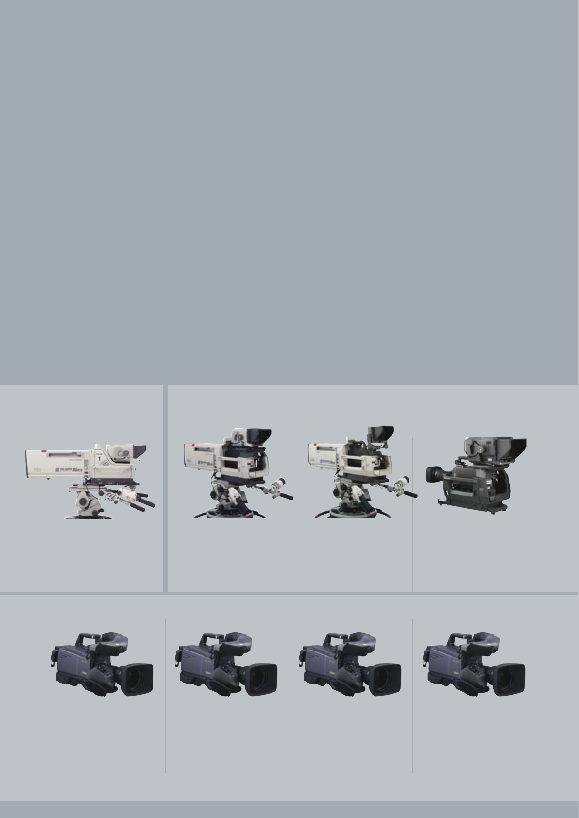
Studio Camera Large Lens/Viewfinder Adaptor
Portable Cameras
HDLA-1507
(for HDVF-700A/9900)
HDC-1000
Optical-fibre interface
1080/50i, 59.94i
1080/23.98P, 24P, 25P, 29.97P
1080/50P*, 59.94P*
720/50P, 59.94P
HDLA-1505
(for HDVF-C950W/C730W)
HDLA-1500
(for HDVF-700A/9900)
HDC-1500
Optical-fibre interface
1080/50i, 59.94i
1080/23.98P, 24P, 25P, 29.97P
1080/50P*, 59.94P*
720/50P, 59.94P
HDC-1550
Triax interface
1080/50i, 59.94i
1080/23.98P, 24P, 25P, 29.97P
720/50P, 59.94P
HDC-1450
Triax interface
1080/50i
720/50P
HDC-1400
Optical-fibre interface
1080/50i
720/50P
The Sony HDC-1000 system camera family is based on more than 20 years of development
of HD TV systems and has been the first choice for literally hundreds of broadcasters for both studio
and OB applications. Many thousands of HDC-1000 systems have been sold around the world
since the introduction in 2005 and the family has continued to improve and grow since then.
Recent additions include the acclaimed HDC-3300 Slow-motion system (in a separate brochure) and
the HDC-1400 and HDC1450 dual format cameras.
3
* 1080/59.94P and 1080/50P signals can be output only from the HDC-1000/HDC-1500 camera head in a stand -alone configuration.
Page 4
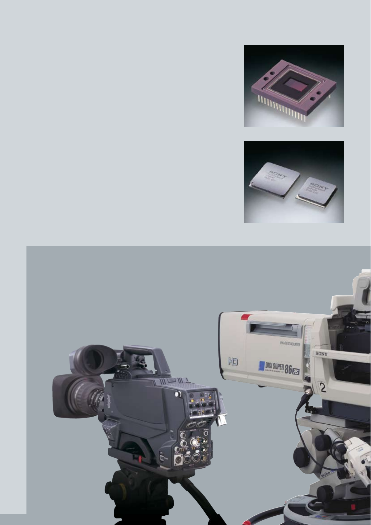
Newly Developed Progressive CCD
At the heart of the outstanding picture performance of the HDC-1000 Series of cameras is a newly developed 2⁄3-inch type
2.2-megapixel HD CCD. Based on Sony HAD
sensor technology and the latest on-chip
lens structure, this CCD offers a high sensitivity
of F11 at 2,000 lx and an excellent signalto-noise ratio of 54 dB (typical).
In addition to this performance, a wide variety of capturing modes including 1080/50i,
1080/59.94i, 1080/23.98P, 1080/24P, 1080/25P,
and 1080/29.97P are available.
What’s more, this CCD can capture topquality 1080/59.94P1 and 1080/50P1 images
- a capability that also offers highest possible quality 720/50P and 720/59.94P image
acquisition.
2
1 1080/59.94P and 1080/50P signals can be output only
from the HDC-1000/HDC-1500 camera head in a
stand-alone configuration via dual-link.
2 The HDC-1400/HDC-1450 supports 1080/50i and
720/50p.
High-quality 14-bit A/D Conversion
The HDC-1000 Series of cameras incorporates a high-performance 14-bit A/D
converter that enables images captured
by the high-performance CCDs to be processed with maximum precision. In particular,
this high-resolution A/D conversion allows
the gradation in mid-to-dark-tone areas
of the picture to be faithfully reproduced.
Thanks to the 14-bit A/D converter, pre-knee
signal compression at highlight areas can
be eliminated and the camera can clearly
reproduce a high-luminance subject at
a 600% dynamic range.
State-of-the-art DSP LSI
The newly developed DSP (Digital Signal Processing) LSI “Visual Image Processor” is at the
heart of the image-processing device for the
HDC-1000 Series of cameras. By adopting
the latest 0.11 mm design rule, this processor can accommodate up to 1080/59.94
and 1080/50 progressive formats and
14-bit resolution, maximising the high-clarity
images captured by the CCD. In addition,
white balance, white shading, and flare
are digitally corrected, allowing for stable
image correction. Processing is performed
with more than 30 bits accuracy to ensure
freedom from rounding artefacts.
Cutting-edge Technologies
New Progressive CCD
New developed DSP
4
HDC-1500 HDC-1000
Page 5
Great Operability
Ergonomic Design
The design of the HDC-1000 Series of cameras is based on over two decades of Sony experience in manufacturing broadcast video
cameras and camcorders, and provides a
high level of operability. All control switches
and connectors are in the most logical places for optimum functionality and ease of
use. The low-profile body of the HDC-1000
camera minimises the parallax between
the optical axis of the camera head and
the large viewfinder, while the HDC-1400/
HDC-1450/HDC-1500/HDC-1550’s low centre
of gravity design allows the operator to carry
the camera comfortably on the shoulder.
In addition, the shoulder pad of these cameras can be adjusted either forwards or
backwards without using a screwdriver, so
the camera can easily be moved to a wellbalanced position.
Optical Fibre Digital Transmission
(HDC-1000/HDC-1400/HDC-1500)
The HDC-1000/HDC-1400/HDC-1500 camera
comes equipped with an SMPTE standard
optical fibre interface for connecting its associated HDCU-1000/HDCU-1500 Camera
Control Unit.
In addition to its exceptional quality, the
camera can transmit all-digital bi-directional video and audio signals, one control
line, and prompter line over extremely long
distances – up to 3000 meters (9843 feet)3
with the HDCU-1000 and 1800 meters (5906
feet)3 with the HDCU-1500.
3 When supplying power to the camera via the optical
fibre cable, the maximum cable length varies with
the camera system configuration, lens type, and the
number of cable connectors.
Choice of Two Camera
Control Systems
In a multi-camera configuration featuring
the HDC-1000 Series, two types of camera
control system can be used. One is based on
the CNU-700 Camera Command Network
Unit at the centre of the configuration,
while the other makes use of the Ethernet
functionality of the systems – a new and
powerful feature that also provides a path
to the future. Both control systems allow
communication between all the devices
in the configuration, including cameras,
camera control units, remote controllers,
and setup units.
Wide-band Triax Transmission
(HDC-1450/HDC-1550)
The HDC-1450/HDC-1550 camera comes
equipped with a widely-used triax transmission interface. This enables the camera to
transmit bi-directional video and audio signals, and one control line to the HDCU-1000/
HDCU-1500 Camera Control Unit via the
HDFX-100 unit over long distances - up to
1400 meters (4593 feet)4 with a ø14.5 mm
triax cable or 1000 meters (3281 feet)4 with
a ø11 mm triax cable.
4 When supplying power to the camera via the triax
cable, the maximum cable length varies with the
camera system configuration, lens type, the size of the
triax cable, and the number of cable connectors.
Compact and Lightweight
HDC-1400/HDC-1500/HDC-1550 portable
cameras are designed to be very compact
and lightweight for a high level of mobility
in the field. The HDC-1400/HDC-1500 and
HDC-1450/HDC-1550 cameras weigh approximately 4.5 kg and 4.9 kg respectively.
Versatile Interfaces
The HDC-1000/HDC-1500 camera and the
HDC-1400/HDC-1450/HDC-1550 camera
provide two HD-SDI outputs and one HD-SDI
output respectively, as well as one digitally
down-converted SD-SDI or analogue composite output. In addition, the viewfinder
signals with characters can be output from
the SD-SDI output connector, giving camera
operators additional convenience. Furthermore, for 24P5 operation, the built-in 2-3
pull-down function of the cameras enables 59.94i down-converted SD signals to
be output on a standard SD monitor.
5 Not supported by HDC-1400/HDC-1450
Memory Stick Storage of Camera
Setup Parameters
The HDC-1000 Series is capable of saving and
recalling setup parameters such as scene
files, reference files, and lens files via Memory
Stick™ media. This allows users to effectively
manage camera parameters for individual
scenes, plus the specific camera-setup preferences of individual operators, such as
viewfinder indicator settings.
Servo-controlled ND and CC Filters
The HDC-1000/HDC-1500/HDC-1550 camera
comes equipped with dual optical filters
for ND (Neutral Density) and CC (Colour
Correction), while the HDC-1400/HDC-1450
camera is equipped with a single optical filter
for ND and electronic colour correction.
The filters can be remotely controlled
from an RCP Series Remote Control Panel,
MSU-900/950 Master Setup Unit, or RM-B750/
B150 Remote Control Unit as well as locally
controlled on the camera head.
5
Page 6
Responding to the ever-increasing
requirement of operations that
combine a portable camera with
a large lens, Sony has developed
the optimum solution.
The highly sophisticated HDLA-1500
and HDLA-1505 Large Lens Adaptors
are designed to maximise operability
of the HDC-1400/HDC-1450/HDC-1500/
HDC-1550 camera. Until now, setting up a
portable camera with a large lens adaptor has been a difficult task, especially
fine-tuning the mechanical adjustments
between each device. With the HDLA-1500/
HDLA-1505 Large Lens Adaptor, timeconsuming adjustments, as well as re-wiring,
are absolutely eliminated.
Another convenient peripheral for the
portable cameras, the HDLA-1507 Large
Viewfinder Adaptor, is also available,
enabling a large viewfinder to be used with
the portable camera.
HDLA-1500/HDLA-1505/HDLA-1507 – Maximising Operability
6
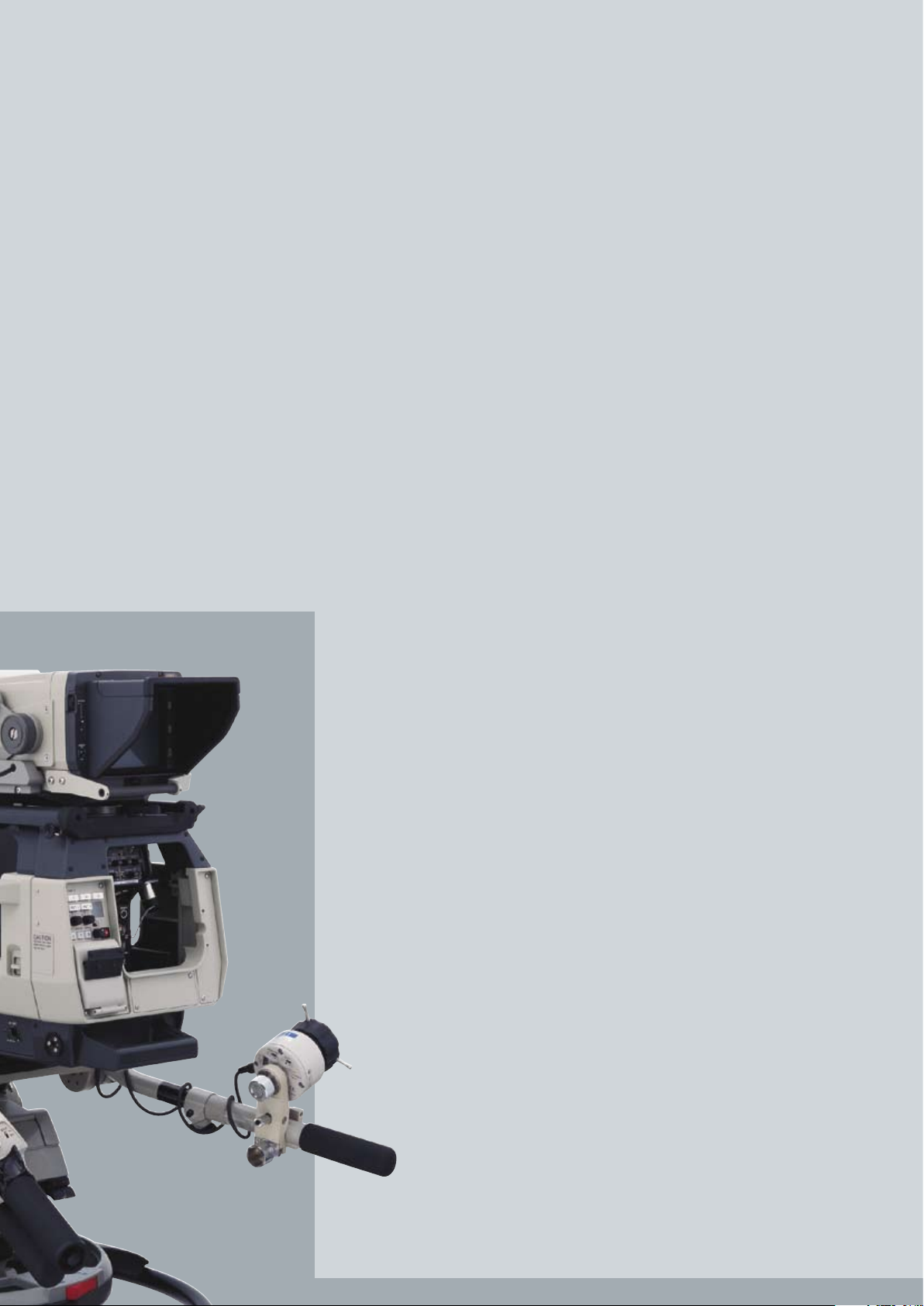
Docking 1
Open the rear cover of the HDLA Series
adaptor. There is no need to detach the
viewfinder.
Totally New Interlocking
Mechanism
The HDLA-1500/HDLA-1505/HDLA-1507
adaptor does not require any cable
wirings. Utilising a newly developed interlocking mechanism, the power, video
and control signals are passed on directly
from the portable cameras to the HDLA
Series adaptor. This unique mechanism also
allows the portable cameras to be attached
and detached without removing the large
lens. Furthermore, the lens can be removed
even when the camera is mounted on the
HDLA-1500/HDLA-1505 adaptor. The interlocking mechanism allows for an astonishingly
quick and smooth setup.
Low-profile Design
Together with the low-profile design of the
portable camera, the viewfinder position
of the HDLA-1500 is 45 mm lower than
the previous model. This low-profile design
significantly improves the operator’s view,
as well as minimizes the parallax between
the optical axis of the camera head and
viewfinder.
with HDVF-700
(Large Lens and CRT Viewfinder)
HDLA-1500
Page 7

7
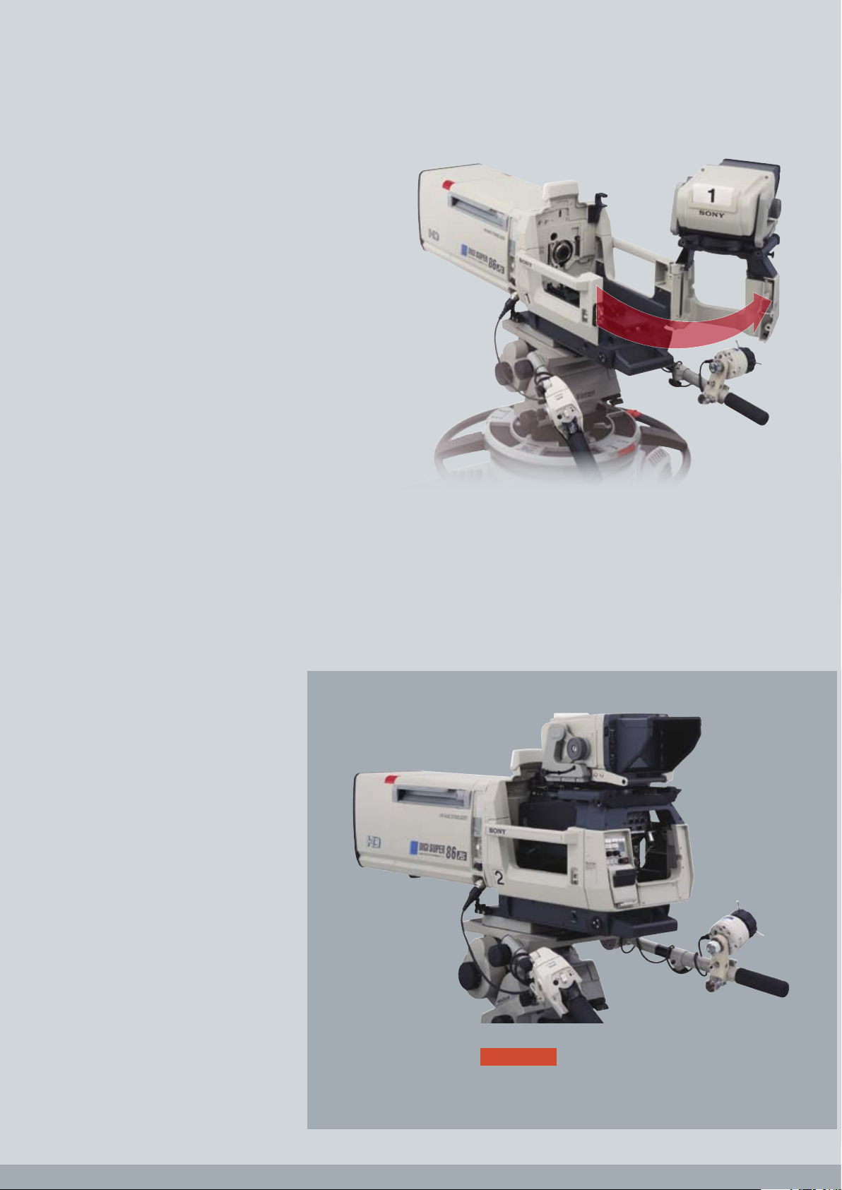
Docking 3
Close the rear cover and then slide the
viewfinder forward.
Docking 2
Mount the portable camera and slide
forward until you hear the locking click.
with HDVF-C730W
(Large Lens and LCD Viewfinder)
with HDVF-9900
(2/3" Lens and CRT Viewfinder)
HDLA-1505 HDLA-1507
Page 8

Digital Extender
1
The Digital Extender function of the
HDC-1000 Series of cameras2 enables
images at the centre of the shot to be
digitally doubled in size. Unlike lens extenders, the Digital Extender function performs
this capability without any loss in image
sen-sitivity.
1 Use of the digital extender function will reduce the
resolution of the image by half.
2 The HDC-1400/HDC-1450 do not support the digital
extender function.
Creative Versatility
8
Triple Skin Tone Detail Correction
Skin Tone Detail Correction controls the detail
level of those objects in a scene with specific
colour tones.
The HDC-1000 Series of cameras allows detail
to be set independently for each of three
separate colour ranges. These colours are
not limited to skin tones, but can be set for
any colour. Detail may be increased or decreased relative to the normal level.
Multi-matrix
OFF
Multi-matrix
ON
Skin Tone Detail
OFF
Skin Tone Detail
ON
Digital Extender
OFF
Digital Extender
ON
Multi-matrix
The Multi-matrix function of the HDC-1000 Series
of cameras allows colour adjustments to be
applied over the colour range specified by the
operator. The colour spectrum is divided into
16 areas of adjustment, where the hue and/or
saturation of each area can be modified.
This function is especially useful when only the
hue of certain colours needs to be adjusted
in critical applications.
Page 9

9
Knee Saturation
Traditionally, very bright parts of a scene
(such as key light from a person’s forehead)
suffer from a loss of saturation or a change in
hue. The HDC-1000 family provide a ‘Knee
Saturation’ function, which can counteract this effect and achieve a more natural
appearance in these difficult areas.
Selectable Gamma Table
The selectable gamma table provided with
the HDC-1000 Series cameras allows users
to create a specific look for a picture by
selecting from a choice of fixed gamma
patterns.
Variable Black Gamma
The Variable Black Gamma function
for the HDC-1000 Series of cameras allows
for fine adjustment of tonal reproduction in
the shadow area. This feature can help to
bring out details from the dark parts of the
picture without affecting mid-tones while
maintaining the absolute black level.
Low-key Saturation
OFF
Low-key Saturation
ON
Standard Video Gamma Variable Black Gamma ON
Knee Saturation
OFF
Knee Saturation
ON
Simulated imagesSimulated images
Low-key Saturation
With conventional cameras, low light areas
can be subject to a reduction in saturation.
This can result in colours in those areas being
lost. The Low-Key Saturation function on the
HDC-1000 Series of cameras eliminates this
problem by optimising the amplification of
colour saturation at low light levels, providing
more natural colour reproduction.
Page 10

The HDC-1000 Series of cameras
is compatible with a variety of peripherals including camera control
units, remote controllers, command
network units, and master setup units.
This allows operators to flexibly configure the system according to their
needs both in the studio and out in
the field. Optional triax adaptors are
available for the HDC-1000/
HDC-1400/HDC-1500 optical fibrebased camera to enable triax-based
operation.
Versatile System Components
10
HDCU-1000 Full-size
Camera Control Unit
HDCU-1500 Half-rack-size
Camera Control Unit
The HDC-1000 Series of cameras can be configured with two types of camera control unit
– the full-size HDCU-1000 and half-rack-size
HDCU-1500. The optical fibre transmission
system used in these units maintains the high
picture quality of the camera across cable runs
of up to 3000 meters (9843 feet)1 with the HDCU1000 and up to 1800 meters (5906 feet)1 with
the HDCU-1500. Both models are equipped
with a comprehensive range of built-in interfaces such as HD-SDI/SD-SDI outputs, HD-SDI/
SD-SDI/analogue composite return inputs,
and a down-converted analogue composite
monitor output. In addition, a variety of output
interfaces are offered via optional boards,
which can be installed in four slots on the
HDCU-1000 and two slots on the HDCU-1500.
Furthermore, the Ethernet interface (10Base-T/
100Base-TX) that is built into both CCUs
allows the camera to be controlled over a
network.
1 When supplying power to the camera via the optical
fibre cable, the maximum cable length varies with the
camera system configuration, lens type, viewfinder
type, and the number of cable connectors.
> Eight HD-SDI or SD-SDI outputs
> Up to eight additional HD-SDI or SD-SDI outputs
(with two optional HKCU-1005 boards)
> Four sets of HD-SDI, SD-SDI, and analogue composite
return video inputs
> Two-channel teleprompter inputs
> Built-in Ethernet interface(10Base-T/100Base-TX)
> Two-channel data trunk lines (RS-422A or RS-232C)
for easy data transmission
> AES/EBU digital audio output
> Two-channel microphone outputs (two XLR connectors)
> High power capability
Rear Panel
> The HKCU-1001 SD Analogue Interface
Unit provides two analogue NTSC or PAL
VBS signal outputs, a PIX (picture monitor)
output, and a WFM (waveform monitor)
output.
Three types of interface expansion option are available for both CCUs.
HDCU-1000
> The HKCU-1003 Multi Interface Unit consists
of three types of interface board and
provides:
– Two analogue NTSC or PAL VBS signal outputs,
a PIX output, and a WFM output (Board A)
– A frame reference input, output to lock 2-3
pull-down sequence, a PIX output, and a WFM
output (Board B)
– Analogue NTSC or PAL VBS and analogue com-
ponent R/G/B or Y/R-Y/B-Y outputs (Board C)
Page 11

11
> Compact CCU
> Three HD-SDI or SD-SDI outputs
> Up to eight additional HD-SDI or SD-SDI outputs
(requires two optional HKCU-1005 boards)
> Three HD-SDI, SD-SDI, or analogue composite return
video inputs
> RM-B750 Remote Control Unit attach capability
on the front panel
> One-channel teleprompter input
> Built-in Ethernet interface (10Base-T/100Base-TX)
> Two-channel data trunk line (RS-422A/RS-232C)
for easy data transmission
> Two-channel microphone outputs (two XLR connectors)
Remote Control Unit
The RM-B750 Remote Control Unit has been
designed to offer a highly mobile and fully
controllable camera system in the field.
The RM-B750 can be connected directly to
the HDC-1000 Series camera or attached
to the half-rack-size HDCU-1500 Camera
Control Unit. The combination of an LCD
touch-panel screen and direct push buttons
enables full parameter adjustment of the
camera to be controlled. For further operational convenience, the RM-B750 has
a Memory Stick media card slot so that
various setup parameters can be stored and
recalled.
Rear Panel
The RM-B750 attached
to the HDCU-1500
HDCU-1500 RM-B750
> The HKCU-1005 HD/SD Output Expansion
Unit provides 4 additional HD SDI or SD
SDI outputs.
HKCU-1001
SD Analogue
Interface Unit
HKCU-1003
Multi Interface Unit
HKCU-1005 HD/SD
Expansion Unit
Page 12

12
MSU-900 MSU-950
Four types of Sony Remote Control
Panel - the RCP-750, RCP-751, RCP-920,
and RCP-921 - are available, providing
a wide range of camera parameter controls. The RCP-750/751 offers
in-depth menu-based controls, while
the RCP-920/ 921 allows direct and
quick control of various parameters
using dedicated buttons on the panel.
The RCP-750 and 751 are connected
to the CCU via dedicated cabling.
The RCP-920 and 921 can also be
connected and powered directly
from a (POE) network hub.
RCP-750 RCP-751 RCP-920 RCP-921
Camera Command Network Unit
The CNU-700 Camera Command Network
Unit allows communication between
all the units in the system, and provides
the ability to assign CCUs, MSUs, RCPs,
and HDC-1000 Series camera heads.
A RISC-based microprocessor system provides high-speed transfer of command
signals to the HDCU-1000/HDCU-1500 Camera Control Unit for rapid response and
reliable control.
One CNU-700 unit can control six cameras, but can be expanded to control up to
12 cameras when fitted with an optional
BKP-7930 Expansion Board.
Several CNU-700 units can be connected to the camera control network in
a large system. The CNU-700 supports
RCP assignment.
Versatile System Components
The MSU-900/950 Master Setup Unit is
a central control panel used for the
adjustment of camera parameters
in a multi-camera system. The MSU900/950 unit is connected to each
camera control unit in the system via
the CNU-700 Command Network Unit
or an Ethernet network hub.
> Central control of camera parameters for the entire camera system
(up to 24 cameras)
> Picture and waveform monitor switching
> Precise picture adjustment
> Built-in 6.5-inch
1
type LCD display for clear viewing of adjustment
parameters during operation
> Memory Stick slot for storing/recalling files
> Built-in Ethernet interface (10Base-T/100Base-TX)
1 Viewable area measured diagonally
MSU-900/950
RCP Series
CNU-700
Remote Control Panel
Master Setup Unit
Page 13

13
HD Triax Adaptor (Camera side)
HD Triax Adaptor (HDCU side)
The HDTX-100 and HDFX-100 HD Triax Adaptors are available to convert optical fibre
transmission to the widely-used triax transmission. The HDTX-100 adaptor is used with
the HDC-1000/HDC-1400/HDC-1500 camera1 to convert their camera output to triax,
while the HDFX-100 adaptor is used with the HDCU-1000/HDCU-1500 camera control
unit to receive triax signals from the camera side.
The triax-based system enables high-quality pictures to be transmitted from the
cameras over long distances - up to 1400 meters (4593 feet)2 with a ø14.5 mm triax
cable or 1000 meters (3281 feet)2 with a ø11 mm triax cable. In addition, the HDTX-100
adaptor enables hybrid triax and optical fibre operation. In this case, longer cable runs
of more than 2000 meters (6562 feet)2 can be achieved with the HDC-1400/HDC-1500
portable camera that is equipped with a portable lens and a small viewfinder.
1 The HDC-1450/HDC-1550 does not require the HDTX-100 unit because it is equipped with a triax output
as standard.
2 When supplying power to the camera via the optical fibre cable and/or triax cable, the maximum cable
length varies with the camera system configuration, lens type, viewfinder type, diameter of the triax cable
and the number of cable connectors.
HDTX-100 (Triax powered)
HDFX-100 (Requires mains power)
Triax and Optical Fibre Operation
HDC-1450/HDC-1550
HDC-1450/HDC-1550 + HDLA-1500/HDLA-1505
HDC-1000
HDC-1500+HDLA-1500/HDLA-1505
HDC-1400/HDC-1500
Max.1000 m
HDTX-100
HDTX-100
HDFX-100
HDFX-100
HDFX-100
TRIAX CABLE
OPTICAL FIBRE CABLE
HDCU-1500
HDCU-1500
HDCU-1500
HDCU-1000
HDCU-1000
HDCU-1000
HDTX-100
HDFX-100
Page 14

14
MSU-950
Versatile System Components
CCD Block Extension Adaptor
The HKC-T1500 CCD Block Extension Adapter is a unique accessory for HDC-1400/
HDC-1450/HDC-1500/HDC-1550 portable
cameras. It allows the CCD block to be
extended from the camera body by up
to 12.5 m (or 50 m with an optional cable).
More creative camera shooting angles can
be achieved, along with the freedom to
place the imaging assembly in areas where a full-size camera would be restricted.
The HKC-T1500 adaptor will expand the
spectrum of HD camera applications in area
such as snorkel lenses, helicopter gimbal
mounts, and mini jibs.
HKC-T1500 connected
to the HDC-1500
Control/Intercom Panels and Connectors
1
POWER
R G B RET 2
FILTER LOCAL
ND
2
3
4
1
5
2
3
4
1
2
3
4
1
CC
B
C
D
A
E
H-POSI V-POSI
WIDTH HEIGHT STORE
CURSOR
VF DETAIL
1 2 3
ON
UP TALLY
ON
OFF
16:9
4:3
VF
SCAN
ON
OFF
SCREEN SIZE
MARKER
ON
OFF
MARKER
ON
OFF
ON
OFF
MIX VF
ON
MENU
DISPLAY
OFF
MENU SELECT
CANCEL ENTER
CALL
RET 1
ASSIGN-
ABLE
HDC-1000
Control Panel
1
POWER
R G B RET 2
FILTER LOCAL
ND
2
3
4
1
5
2
3
4
1
2
3
4
1
CC
B
C
D
A
E
H-POSI V-POSI
WIDTH HEIGHT STORE
CURSOR
VF DETAIL
1 2 3
ON
UP TALLY
ON
OFF
16:9
4:3
VF
SCAN
ON
OFF
SCREEN SIZE
MARKER
ON
OFF
MARKER
ON
OFF
ON
OFF
MIX VF
ON
MENU
DISPLAY
OFF
MENU SELECT
CANCEL ENTER
CALL
RET 1
ENG PROD
INTERCOM
PTT ONOFF
PGM1
MIC
INTERCOM 1 INTERCOM 2
PGM2
ENG PROD
INTERCOM
PTT ONOFF
PGM1
MIC
PGM2
ASSIGN-
ABLE
Intercom Panel
1
1
SDI 1 SDI 2 TEST OUT
OUTPUT PROMPTER REMOTE
1 2
CRANE TRACKER RET
CONTROL
DC OUT
DC IN
AUDIO IN 1
MIC
LINE
MICOFF
+48V
OFF
+48V
AUDIO IN 2
AES/EBU
LINE
Connectors – Outside Panel
1
SDI 1 SDI 2 TEST OUT
OUTPUT PROMPTER REMOTE
1 2
CRANE TRACKER RET
CONTROL
DC OUT
Connectors – Inside Panel
HDC-1400/HDC-1450/HDC-1500/HDC-1550
RET1
ENG PROD
1
2 3
4
RET2
LIGHT
INTERCOM 1
ON
OFF
MIC
LINE1
PROD
OFF
ENG
MIC
LINE2
PROD
OFF
ENG
PGM1 PGM2
TRACKER
INTERCOM 2
LEVEL
REAR
FRONT
1
2 3
4
Control/Intercom Panel
OFF
+48V
MIC
FRONT MIC
DC OUT
AUDIO IN
CH1 CH2
TEST
OUT
SDI 2
DC IN 10.5-17V
PROMPTER
RET IN
GENLOCK IN
LINE
OFF
+48V
MIC
AES/EBU
LINE
EARPHONE
REMOTE
RET CTRL
CRANETRACKER
HDC-1400/1450/1500/HDC-1550
Connectors
HKC-T1500
Page 15

15
Optional Accessories
HDLA-1500
Large Lens Adaptor
(for attachment of the
HDVF-700A/9900)
HDLA-1505
Large Lens Adaptor
(for attachment of the
HDVF-C950W/C730W)
HDLA-1507
Large Viewfinder Adaptor
(for attachment of the
HDVF-700A/9900)
RM-B150
Remote Control Unit
RM-B750
Remote Control Unit
RCP-920/921
Remote Control Panel
(Photo shows RCP-920)
RCP-750/751
Remote Control Panel
(Photo shows RCP-750)
HDVF-20A
2.0-inch* CRT B/W Viewfinder
HDVF-C35W
3.5-inch* LCD Colour Viewfinder
HDVF-C950W
9.0-inch* LCD Colour Viewfinder
VFH-990
Outdoor Hood for HDVF-C950W
HDVF-C730W
6.3-inch* LCD Colour Viewfinder
HDVF-700A
7.0-inch CRT B/W Viewfinder
VFH-770
Outdoor Hood for
HDVF-700A/C730W
HDVF-9900
9.0-inch CRT Colour Viewfinder
BKW-401
Viewfinder Rotation Bracket
BKP-7911
Script Holder
CAC-6
Return Video Selector
CAC-12
Mic Holder
VCT-14
Tripod Adaptor
Page 16

REMOTE CONTROL PANEL
RCP-700/920 SERIES
CCA-5 CABLE
CAMERA COMMAND
NETWORK UNIT CNU-700
CCA-5 CABLE
MASTER SETUP UNIT
MSU-900
MASTER SETUP
UNIT MSU-950
ETHERNET
CONNECTION
ETHERNET
CONNECTION
CCA-5 CABLE CCA-5 CABLE CCA-5 CABLE
CAMERA CONTROL UNIT
HDCU-1000
ETHERNET
CONNECTION
HKCU-1001
HKCU-1003
HKCU-1005
FIBRE CABLE
WF 2
PIX 2
VIDEO SELECTOR
VCS-700 (SD analogue)
CAMERA CONTROL UNIT
HDCU-1000
CAMERA CONTROL
UNIT HDCU-1500
ETHERNET
CONNECTION
ETHERNET
CONNECTION
PIXWF WF 2
PIX 2
HKCU-1001
HKCU-1003
HKCU-1005
FIBRE CABLE
STUDIO ZOOM LENS
COLOUR VIDEO
CAMERA HDC-1000
CRT B/W VIEWFINDER
HDVF-700A
CRT COLOUR VIEWFINDER
HDVF-9900
CRT B/W VIEWFINDER
HDVF-20A
LCD COLOUR VIEWFINDER
HDVF-C35W
ENG/EFP LENS
COLOUR VIDEO CAMERA
HDC-1400/HDC-1500
LCD COLOUR VIEWFINDER
HDVF-C730W/C950W
STUDIO ZOOM LENS
LARGE LENS ADAPTOR
HDLA-1505
SCRIPT HOLDER
BKP-7911
STUDIO ZOOM LENS
LARGE LENS ADAPTOR
HDLA-1500
ENG/EFP LENS
LARGE VIEWFINDER
ADAPTOR HDLA-1507
CRT B/W VIEWFINDER
HDVF-700A
CRT COLOUR VIEWFINDER
HDVF-9900
CRT B/W VIEWFINDER
HDVF-700A
CRT COLOUR VIEWFINDER
HDVF-9900
16
System Configuration for
Optical Fibre Operation
Page 17

REMOTE CONTROL PANEL
RCP-700/920 SERIES
CCA-5 CABLE
CAMERA COMMAND
NETWORK UNIT CNU-700
CCA-5 CABLE
MASTER SETUP UNIT
MSU-900
MASTER SETUP
UNIT MSU-950
ETHERNET
CONNECTION
ETHERNET
CONNECTION
CCA-5 CABLE CCA-5 CABLE CCA-5 CABLE
CAMERA CONTROL UNIT
HDCU-1000
ETHERNET
CONNECTION
HKCU-1001
HKCU-1003
HKCU-1005
FIBRE CABLE
WF 2
PIX 2
VIDEO SELECTOR
VCS-700 (SD analogue)
CAMERA CONTROL UNIT
HDCU-1000
CAMERA CONTROL
UNIT HDCU-1500
ETHERNET
CONNECTION
ETHERNET
CONNECTION
PIXWF WF 2
PIX 2
HKCU-1001
HKCU-1003
HKCU-1005
FIBRE CABLE
CRT B/W VIEWFINDER
HDVF-20A
LCD COLOUR VIEWFINDER
HDVF-C35W
ENG/EFP LENS
TRIAX ADAPTOR
HDFX-100
STUDIO ZOOM LENS
LARGE LENS ADAPTOR
HDLA-1505
STUDIO ZOOM LENS
LARGE LENS ADAPTOR
HDLA-1500
ENG/EFP LENS
LARGE VIEWFINDER
ADAPTOR HDLA-1507
CRT B/W VIEWFINDER
HDVF-700A
CRT COLOUR VIEWFINDER
HDVF-9900
CRT B/W VIEWFINDER
HDVF-700A
CRT COLOUR VIEWFINDER
HDVF-9900
17
TRIAX ADAPTOR
HDFX-100
TRIAX CABLETRIAX CABLE
TRIAX ADAPTOR
HDTX-100
COLOUR VIDEO CAMERA
HDC-1450/HDC-1550
LCD COLOUR VIEWFINDER
HDVF-C730W/C950W
System Configuration
for Triax Operation
ENG/EFP LENS
COLOUR VIDEO CAMERA
HDC-1450/HDC-1550
STUDIO ZOOM LENS
COLOUR VIDEO
CAMERA HDC-1000
CRT B/W VIEWFINDER
HDVF-700A
CRT COLOUR
VIEWFINDER
HDVF-9900
SCRIPT HOLDER
BKP-7911
FIBRE CABLE
TRIAX CABLE
Page 18

18
HDC-1000/1400/1450/1500/1550 Specifications
HDC-1000 HDC-1400 HDC-1450 HDC-1500 HDC-1550
General
Power requirements
240 V AC, 1.7 A (max.),
180 V DC, 0.9 A (max.),
12 V DC, 10 A (max.)
240 V AC, 1.4 A (max.),
180 V DC, 1.0 A (max.),
12 V DC, 7 A (max.)
180 V DC, 1.0 A (max.),
12 V DC, 7 A (max.)
240 V AC, 1.4 A (max.),
180 V DC, 1.0 A (max.),
12 V DC, 7 A (max.)
180 V DC, 1.0 A (max.),
12 V DC, 7 A (max.)
Operating temperature -20 °C to +45 °C (-4 °F to +113 °F)
Storage temperature -20 °C to +60 °C (-4 °F to +140 °F)
Mass 21 kg (46 lb 5 oz) 4.5 kg (9 lb 15 oz) 4.9 kg (10 lb 13 oz) 4.5 kg (9 lb 15 oz) 4.9 kg (10 lb 13 oz)
Camera
Pickup device 3-chip 2/3-inch type CCD
Effective picture elements (H x V) 1920 x 1080
Signal format
1080/50i, 59.94i, 23.98P,
24P, 25P, 29.97P50P, 59.94P
1080/50P*, 59.94P*
720/50P, 59.94P
1080/50i, 720/50P
1080/50i, 59.94i, 23.98P,
24P,25P, 29.97P50P, 59.94P
1080/50P*, 59.94P*
720/50P, 59.94P
1080/50i, 59.94i, 23.98P,
24P, 25P, 29.97P
720/50P, 59.94P
Spectrum system F1.4 prism system
Lens mount Sony hanger mount Sony bayonet mount
Built-in filters
CC
A: CROSS, B: 3200K,
C: 4300K, D: 6300K,
E: 8000K
— A: CROSS, B: 3200K, C: 4300K, D: 6300K, E: 8000K
ND
1: CLEAR, 2: 1/4ND,
3: 1/8ND, 4: 1/16ND,
5: 1/64ND
1: CLEAR, 2: 1/4ND, 3: 1/16ND, 4: 1/64ND, 5: CROSS 1: CLEAR, 2: 1/4ND, 3: 1/8ND, 4: 1/16ND, 5: 1/64ND
Sensitivity (at 2000 lx, 3200K,
89.9% reflectance)
F10 (1080/59.94i), F11(1080/50i)
Signal-to-noise ratio (1080i) 54 dB
Horizontal resolution (1080i) 1000 TV lines (at center)
Registration Within 0.02% (all zones, without lens)
Shutter speed selection
1/100, 1/125, 1/250, 1/500,
1/1000, 1/2000 s (1080/59.94i)
1/60, 1/125, 1/250, 1/500,
1/1000, 1/2000 s (1080/50i)
1/60, 1/125, 1/250, 1/500, 1/1000, 1/2000 s
1/100, 1/125, 1/250, 1/500, 1/1000, 1/2000 s (1080/59.94i)
1/60, 1/125, 1/250, 1/500, 1/1000, 1/2000 s (1080/50i)
Modulation depth (1080i) 45% horizontally (typical) (800 TV lines at center, 27.5 MHz, with typical lens)
Input/output connectors
Audio input (CH1)
XLR-3-31 type (male) (1),
mic or line selectable
XLR-3-pin (female) (1), mic or line selectable
Audio input (CH2)
XLR-3-31 type (male) (1),
AES/EBU or mic or line
selectable
XLR-3-pin (female) (1),
AES/EBU or mic or line
selectable
XLR-3-pin (female) (1),
mic or line selectable
XLR-3-pin (female) (1),
AES/EBU or mic or line
selectable
XLR-3-pin (female) (1),
mic or line selectable
Mic 1 input — XLR-3-pin (female) (1)
Return control input 6-pin (1)
Prompter output/Genlock input/
Return input
— BNC type (1), 1.0 Vp-p, 75 Ω
Prompter — BNC type (1), 1.0 Vp-p, 75 Ω —
Prompter 1 BNC type (1), 1.0 Vp-p, 75
Prompter 2 BNC type (1), 1.0 Vp-p, 75 BNC type (1), 1.0 Vp-p, 75 Ω —
DC input XLR-4-pin (1), 10.5 to 17 V DC
DC output 4-pin (1), 10.5 to 17.5 V DC, 500 mA (max.)
Test output BNC type (1), 1.0 Vp-p, 75Ω
SDI 1 output BNC type (2) HD-SDI — BNC type (2) HD-SDI —
SDI 2 output
BNC type (2) HD-SDI or
SD-SDI selectable
(without embedded audio)
—
BNC type (2) HD-SDI or
SD-SDI selectable
(without embedded audio)
—
SDI output —
BNC type (1) HD-SDI or SD-SDI selectable (without
embedded audio)
—
BNC type (1) HD-SDI or
SD-SDI selectable (without
embedded audio)
Earphone output — Stereo minijack (1)
CCU Electro-optical connector (1) — Electro-optical connector (1) —
HDCU/HDFX — Triax connector (1) —
Tracker 10-pin (1)
Crane 12-pin (1)
Intercom 1 XLR-5-pin (female) (1)
Intercom 2 XLR-5-pin (female) (1)
Remote 8-pin (1)
Lens 36-pin (1) 36-pin (1)
Viewfinder D-sub 25-pin (1) (CRT) 20-pin (1) (LCD and Monocle)
Supplied accessories
Angle adjustment brackets
(2), Front cover (1), Number plates for side panel
(2 sets), Number plates
for up-tally lamp (1 set),
Cable clamp (2),
Operation manual (1)
Operation manual (1), Switch label 1, 2 (1 each)
MSU-900/950 Specifications
MSU-900 MSU-950
General
Power requirements 100 to 240 V AC, 50/60 Hz
Current consumption 0.35 A
Operating temperature +5 to +40 °C (+41 to +104 °F)
Maximum cable length 200 m (656 feet)
Mass 4.5 kg (9 lb 14 oz) 3.7 kg (8 lb 2 oz)
Dimensions (W x H x D) 482 x 67 x 222 mm (19 x 2 3/4 x 8 3/4 inches) 204 x 354 x 67 mm (8 1/8 x 14 x 2 3/4 inches)
Inputs/outputs
Remote
CCU/CNU: 8-pin (1)
AUX: 8-pin (1)
I/O port 50-pin (1)
Ethernet
6-pin (1)
AC input 3-pin (1)
HDLA-1500/1505/1507 Specifications
HDLA-1500 HDLA-1505 HDLA-1507
General
Power requirements 240 V AC (max. 1.2 A)/180 V DC (max. 0.65 A), 12 V DC (max. 9 A)
Operating temperature -20 °C to +45 °C (-4 °F to +113 °F)
Storage temperature -20 °C to +60 °C (-4 °F to +140 °F)
Mass 18.5 kg (40 lb 13 oz) 17.1 kg (37 lb 11 oz) 15.5 kg (34 lb 3 oz)
Input/output connector
Lens 36-pin
DC IN XLR-4-pin (1), 10.5 to 17 V DC
DC OUT
4-pin (1), 10.5 to 17 V DC, max. 1.5 A
Viewfinder D-sub 25-pin (1) (CRT) Camera-mounted LCD D-sub 25-pin (1) (CRT)
Page 19

19
HDCU-1000/1500 Specifications
HDCU-1000 HDCU-1500
General
Power supply 100 V or 120 V or 220 to 240 V AC, 50/60 Hz 100 to 240 V AC, 50/60 Hz
Operating temperature +5 °C to +40 °C (+41 °F to +104 °F) -10 °C to +40 °C (+14 °F to +104 °F)
Storage temperature -20 °C to +60 °C (-4 °F to +140 °F)
Mass 14.8 kg (32 lb 10 oz) 6.5 kg (14 lb 5 oz)
Input/output connectors
Camera
Optical fiber connector (1), 1.485/1.4835 Gb/s Serial Digital x2,
240 V AC power supply
Optical fiber connector (1), 1.485/1.4835 Gb/s Serial Digital x2,
180 V AC power supply
Intercom/Tally/PGM
D-sub 25-pin (1)
INCOM (PD/ENG): 4W/RTS/CC, 0 dB
PGM: 2 systems, 0/-20 dB
PGM: 2 systems, 0/-20 dB
RCP/CNU 8-pin (1)
Trunk A 12-pin (1)
Trunk line D-sub 9-pin (female) (1), RS-232C/422 —
Ethernet RJ-45 (1), 10Base-T/100Base-TX
I/O port D-sub 15-pin (female) (1) —
Input connectors
AC input (1), 100, 110 to 120, 220 to 240 V AC (1), 100 to 240 V AC
Return input
BNC type (4), HD-SDI: SMPTE 292M, 1.485/1.4835 Gb/s
BNC type (4), SD-SDI: SMPTE 259M, 270 Mb/s
BNC type (3), HD-SDI/SD-SDI/VBS selectable
VBS: 1.0 Vp-p, 75 Ω
HD-SDI: SMPTE 292M, 1.485/1.4835 Gb/s
SD-SDI: SMPTE 259M, 270 Mb/s
Reference input
BNC type (2), loop-through output
HD: SMPTE-274M, tri-level sync, 0.6 Vp-p, 75 Ω
SD: Black burst (NTSC: 0.286 Vp-p, 75 Ω/PAL: 0.3 Vp-p, 75 Ω) or NTSC 10F-BB
Prompter imput BNC type (4), loop-through output, analogue signal, 1.0 Vp-p, 75 Ω
Mic remote D-sub 15-pin (1)
Output connectors
Mic output XLR-3-pin (male) (2), 0/-20 dBs
AES/EBU BNC type (1) —
Character output BNC type (1), VBS, 1.0 Vp-p, 75 Ω, character ON/OFF selectable —
Character/Sync output —
BNC type (1), HD sync/SD sync/Character selectable
HD sync: BTA S001A, tri-level sync, 0.6 Vp-p, 75 Ω
SD sync: composite sync, 0.3 Vp-p, 75 Ω
Character: VBS, 1.0 Vp-p, 75 Ω, character ON/OFF selectable
WF remote D-sub 15-pin (female) (1) —
HD-SDI/SD-SDI output
BNC type (4), HD-SDI/SD-SDI selectable
HD-SDI: SMPTE 292M, 0.8 Vp-p, 75 Ω, 1.485/1.4835 Gb/s
SD-SDI: SMPTE 259M, 0.8 Vp-p, 75 Ω, 270 Mb/s
BNC type (2), HD-SDI/SD-SDI selectable
HD-SDI: SMPTE 292M, 0.8 Vp-p, 75 Ω, 1.485/1.4835 Gb/s
SD-SDI: SMPTE 259M, 0.8 Vp-p, 75 Ω, 270 Mb/s
HD-SDI/SD-SDI monitor output
BNC type (4), HD-SDI/SD-SDI, and character ON/OFF selectable
HD-SDI: SMPTE 292M, 0.8 Vp-p, 75 Ω, 1.485/1.4835 Gb/s
SD-SDI: SMPTE 259M, 0.8 Vp-p, 75 Ω, 270 Mb/s
BNC type (1), HD-SDI/SD-SDI, and character ON/OFF selectable
HD-SDI: SMPTE 292M, 0.8 Vp-p, 75 Ω, 1.485/1.4835 Gb/s
SD-SDI: SMPTE 259M, 0.8 Vp-p, 75 Ω, 270 Mb/s
Sync out
BNC type (1), HD sync/SD sync selectable
HD: BTA S001A, tri-level sync, 0.6 Vp-p, 75 Ω
SD: composite sync, 0.3 Vp-p, 75 Ω
—
WF mode 4-pin (2)
Optional input/output boards
HKCU-1001 SD Analogue Interface Unit
VBS output BNC type (2)
Analogue composite monitor output BNC type: WF (1), PIX (1)
HKCU-1003 Multi Interface Unit
VDA-A board: VBS I/F
VBS output
BNC type (2)
Analogue composite monitor output BNC type: WF (1), PIX (1)
VDA-B board: VBS I/F
Frame reference input/output
BNC type (1, loop-through), full pull-down sequence lock
Analogue composite monitor output
BNC type: WF (1), PIX (1)
VDA-C board: Sub I/F
VBS output
BNC type (1)
Analogue component output BNC type (3), R/G/B or Y/R-Y/B-Y selectable
HKCU-1005 HD/SD Expansion Unit
HD SDI/SD SDI output BNC type (2)
HD SDI/SD SDI monitor output BNC type (2), charactor on/off selectable
HKC-T1500 Specifications
General
Power requirements for Camera input 13.5 to 17.0 V DC
Operating temperature -20 ˚C to +45 ˚C (-4 ˚F to +113 ˚F)
Operating humidity 10% to 90% (no condensation)
Mass
Cable adapter: approx. 0.5 kg (1 lb 2 oz)
CCD block adapter: approx. 1.9 kg (4 lb 3 oz) (with CCD block)
CCD block adaptor I/F
Camera cable 55-pin multicore cable connector (male)
MIC IN XLR-3-pin (female) (1)
LENS 12-pin (1)
VF
20-pin (1)
Intercom XLR-5-pin (female) (1)
Cable adaptor I/F
Camera cable 55-pin multicore cable connector (female)
MIC OUT XLR-3-pin (male) (1)
VF 20-pin (1)
INCOM XLR-5-pin (male) (1)
Page 20

© 2008 Sony Corporation. All rights reserved.
Reproduction in whole or in part without written permission is prohibited. Features and specifications are subject to change without notice.
All non-metric weights and measurements are approximate. Sony, Memory Stick and HDVS are trademarks of Sony Corporation.
CA HDC Family/GB- /03/2008
Specialist Dealers receive extensive training on
all Sony’s products and services. They combine
this with an in-depth knowledge of the market,
ensuring you get advice that meets your needs
before and after purchase. To find your nearest
Specialist Dealer visit our “dealer locator” at:
www.sonybiz.net/dealer
Services from Sony
> Working with you, working for you
Recognising that every company and every
challenge is unique, we offer a complete
and comprehensive range of services all
the way through consulting, planning, financing,
implementation, training, servicing, maintenance and support. Choose exactly what’s
right for you, when and where you need it.
> Professional Services
Tailor-made design, installation and project
management of audio-visual and IT (AV/IT)
systems using skills developed over 25 years of
systems integration.
> Financial Services
Innovative and flexible finance solutions designed to meet budgetary and financial requirements and constraints, enabling businesses to
always have the most current technology.
> Training Services
A range of off-the-shelf or customised training
services from basic operation through to highlevel technical maintenance.
> Support Services
Fully integrated and customised support for
products and systems throughout their operational life, combining proactive and reactive
technical services.
Not all services are available in all countries.
If you’d like to find out more about what we do,
who we do it for and how we do it, visit www.
sonybiz.net or contact Sony’s local office.
 Loading...