

Page 1

HCD-RV20/RV50/RV60
E Model
SERVICE MANUAL
Ver 1.1 2003. 08
SUPPLEMENT-1
File this supplement with the service manual.
Subject : Addition of Test Mode, Mechanical Adjustments,
Electrical Adjustments and Block Diagrams.
9-877-378-81
Page 2

HCD-RV20/RV50/RV60
TABLE OF CONTENTS
1. Test Mode ................................................................................ 3
2. Mechanical Adjustments ......................................................... 6
3. Electrical Adjustments............................................................. 7
4. Block Diagram –CD/Video Section– ...................................... 9
5. Block Diagram –Tuner/Tape/Panel Section– ........................ 10
6. Block Diagram –Amp/Power Supply Section– ..................... 11
2
Page 3

HCD-RV20/RV50/RV60
1. TEST MODE
[COLD RESET]
• The cold reset clears all data including preset data stored in the
RAM to initial conditions. Execute this mode when returning the
set to the customer.
Procedure:
1. Press the [POWER] key to turn the power ON.
2. Press three keys of x , [GROOVE] and [POWER] simultaneously.
3. The message “COLD RESET” is displayed on the fluorescent
indicator tube momentarily, then becomes standby states.
[TUNER STEP CHANGE-OVER]
(Except AEP and UK models)
•A step of AM channels can be changed over between 9 kHz and
10 kHz.
Procedure:
1. Press the [POWER] key to turn the power ON.
2. Press the [TUNER BAND] key to select “AM”.
3. Press the [POWER] key to turn the power OFF.
4. Press two keys of [EFFECT ON/OFF] (RV20) or [ENTER] (RV50/
RV60) and [POWER] simultaneously.
5. The message “9K STEP” or “10K STEP” is displayed on the
fluorescent indicator tube, and thus the channel step is changed
over.
[CD SHIP MODE]
•This mode moves the optical pick-up to the position durable to
vibration. Use this mode when returning the set to the customer
after repair.
Procedure:
1. Press the [POWER] key to turn the power ON.
2. Press the [CD] key to select “CD”.
3. Press two keys of [CD] and [POWER] simultaneously.
4. The message “LOCK” is displayed on the fluorescent indicator
tube, and the CD ship mode is set.
[CHANGE-OVER FUNCTION OF MD/VIDEO]
(HCD-RV50/RV60 models)
•This mode is used to enable function of external input to change
over between MD and VIDEO.
Procedure:
1. Set to standby state.
2. Press two keys of [MD VIDEO ] and [POWER] simultaneously.
3. The message “MD” or “VIDEO” is displayed on the fluorescent
indicator tube, and the function of external input is changed
over.
(
)
[CD TRA Y LOCK MODE]
•This mode is used to unable to take sample disc out of tray in the
shop.
Procedure:
1. Press the [POWER] key to turn the power ON.
2. Press the [CD] key to select “CD”.
3. Set disc on the tray.
4. While pressing the x key, press the Z key for 5 seconds.
5. The message “LOCKED” is displayed on the fluorescent
indicator tube and the tray is locked. (Even if pressing
the Z key, the message “LOCKED” is displayed on the
fluorescent indicator tube and the tray is locked)
6. To release from this mode, while pressing the x key, press
the Z key for 5 seconds.
7. The message “UNLOCKED” is displayed on the fluorescent
indicator tube and the tray is unlocked.
[AMP TEST MODE]
•This mode is used to set the parameter of AMP IC for adjustment
of tone quality and VACS level and display VACS status.
Procedure:
1. Press the [POWER] key to turn the power ON.
2. Press three keys of x , [GAME EQ] and [EFFECT ON/OFF]
simultaneously.
3. When the AMP test mode is activated, the message “AMP
TEST” is displayed on the fluorescent indicator tube
momentarily.
4. Press two keys of [GAME EQ] and [DISC 2] simultaneously, mode
is changed over to parameter setting of AMP IC and display of
VACS status.
5. When the VACS status, the message VACS level, VACS signal
level, and VACS signal hold le vel is display ed on the fluorescent
indicator tube.
6. Press the [GROOVE] key, DBFB ON/OFF is changed over.
7. Press the [GAME MIXING] key, surround ON/OFF is changed
over.
8. Press the cursol B and b key, EQ band is changed over to
LOW, MID or HIGH. (Case of HCD-RV50/RV60)
9. Press the cursol V and v key, EQ curve adjustment value is
changed over between –8dB to +8dB. (Case of HCD-RV50/
RV60)
10. To release from this mode, press two keys of [GAME EQ] and
[MOVIE EQ] simultaneously.
3
Page 4
HCD-RV20/RV50/RV60
[AGING MODE]
• This mode can be used for operation check of CD section and
tape deck section.
CD section and tape deck section work in parallel.
If an error occurred:
The aging operation stops only an error occurred sections and
display then status.
If no error occurs:
The aging operation continues repeatedly.
Procedure:
1. Press the [POWER] key to turn the power ON.
2. Press the [CD] key to select “CD”.
3. Set disc on the tray and set tape into the deck.
4. Set the “ALL DISCS” mode and “REV OFF” mode.
5. Press three keys of x , [GAME EQ] and [DISC SKIP/EX-CHANGE]
simultaneously.
6. The message “AGING” is displayed on the fluorescent
indicator tube momentarily, then aging operations of CD and
tape are started at the same time.
7. To release from this mode, operate the “COLD RESET”.
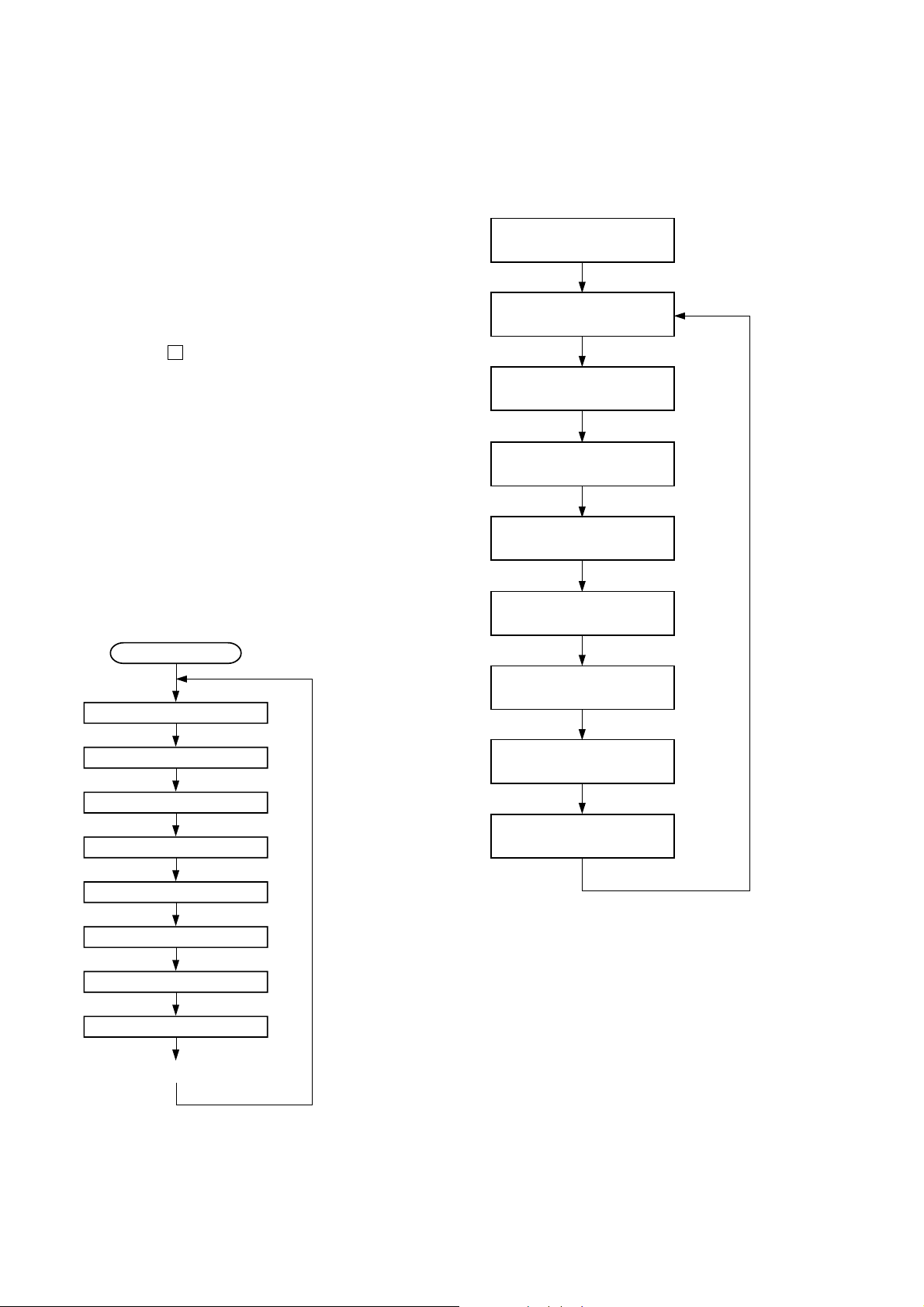
1. Display at the Aging Mode
Display operating state of CD section and tape deck section
alternately.
If an error occurred, stop display which that section.
2. CD Section
The sequence during the aging mode is following as below.
Display at the aging mode is the same as the normal operation.
Aging mode sequence (CD section) :
3. Tape Deck Section
The sequence during the aging mode is following as below.
If an error occurred, stop display that step.
Aging mode sequence (tape deck section) :
Rewind the tape A and B
“AAG-1 or 2”
Shut off
FWD play the tape A
“AAG-3”
2 minutes
Fast forward the tape A
“AAG-4”
Shut off or 20 seconds
REV play the tape A
“AAG-5”
2 minutes
Rewind the tape A
“AAG-6”
Shut off
FWD play the tape B
“BAG-3”
Start (from disc 1)
Disc chucking
TOC read
Play first track for 2 seconds
Play last track for 2 seconds
EX-change open/close
Open the disc tray
Disc skip
Close the tray
Change the next disc.
2 minutes
Fast forward the tape B
“BAG-4”
Shut off or 20 seconds
REV play the tape B
“BAG-5”
2 minutes
Rewind the tape B
“BAG-6”
Shut off
Note: “*AG-*” is display of each step.
4
Page 5

HCD-RV20/RV50/RV60
[GC TEST MODE]
• This mode is used to check the fluorescent indicator tube, LED
and key.
Procedure:
1. Press the [POWER] key to turn the power ON.
2. Press three keys of x , [GAME EQ] and [DISC 2] simultaneously.
3. Fluorescent indicator tube and LEDs are all turned ON.
4. Press two keys of [GAME EQ] and [DISC 2] simultaneously, mode
is changed over.
5. In the key check mode, press each key, the defined key number
of every each key list is displayed on the fluorescent indicator
tube.
6. In the key count check mode, “KEYCNT 0” is displayed on the
fluorescent indicator tube. Each time a key is pressed,
“KEYCNT” value increases. Howev er , once a key is pressed , it
is no longer taken into account.
7. In the headphone input check mode, connect the headphone,
the message “H_P ON” is displayed on the fluorescent
indicator tube, and disconnect the headphone, the message “H_P
OFF” is displayed on the fluorescent indicator tube.
8. In the volume check mode, turn the [VOLUME] knob, the
display on the fluorescent indicator tube is changed over to
“VOLUME UP”, “VOLUME FLAT” or “VOLUME DOWN”
[MC TEST MODE]
•This mode is used to check operations of Amplifier.
Procedure:
1. Press the [POWER] key to turn the power ON.
2. Press three keys of x , [GAME EQ] and [DISC 3] simultaneously.
3. When the MC test mode is activated, the message “TEST
MODE” is displayed on the fluorescent indicator tube
momentarily, then VACS level is displayed on the fluorescent
indicator tube.
4. Press the [MUSIC EQ] key, the display on the fluorescent
indicator tube is changed over to “GEQ MAX”, press the
[EFFECT ON/OFF] key, the display on the fluorescent indicator
tube is changed over to “GEQ 16”, press the [MOVIE EQ] key,
the display on the fluorescent indicator tube is changed over to
“GEQ MIN”,
5. Turn the [VOLUME] knob, the display on the fluorescent
indicator tube is changed over to “VOLUME MAX”, “V OLUME
MID” or “VOLUME MIN”
6. Press the [GROOVE] key, VACS ON/OFF is changed over.
7. When the [REC PAUSE/START] key is pressed with a ta pe set in
the deck-B, the function is switched “MD” or “VIDEO” and
recording starts. When the m or M key is pressed during
recording, the tape is rewound back to the beginning of
recording, the function is switched to “T APE B”, then playback
starts.
8. When the [CD SYNC] key is pressed with the test tape (AMS-
100, AMS-110A) in the deck, number of space between tunes
is counted, then if AMS-110A is set, “OK” is displayed on the
fluorescent indicator tube and if AMS-100 is set, “NG” is
displayed on the fluorescent indicator tube.
9. To release from this mode, press the [POWER] key.
[MODEL, DESTINATION AND VERSION DISPLAY]
•This mode is used to check the model, destination and software
version.
Procedure:
1. Set to the standby state.
2. Press three keys of x , [GAME EQ] and [MOVIE EQ]
simultaneously.
3. When the model, destination and version display mode is
activated, the model an destination is displayed on the
fluorescent indicator tube.
4. Press two keys of [GAME EQ] and [DISC 2] simultaneously, mode
is changed over to model and destination display mode and
version display mode.
5. To release from this mode, press the two keys of [GAME EQ]
and [MOVIE EQ] simultaneously.
[CD ERROR CODE DISPLAY]
• This mode can be used for error display of CD section.
Procedure:
1. Press the [POWER] key to turn the power ON.
2. Press the [CD] key to select “CD”.
3. Press three keys of x , [GAME EQ] and [DISC 1] simultaneously.
Note: Error code is not displayed on the fluorescent indicator tube.
[CD SERVICE MODE]
•This mode can run the CD sled motor freely. Use this mode, for
instance, when cleaning the optical pick-up.
Procedure:
1. Press the [POWER] key to turn the power ON.
2. Press the [CD] key to select “CD”.
3. Press three keys of x , [GAME EQ] and Z simultaneously.
4. When the CD service mode is activated, the message
“TRA VERS ON” is displa yed on the fluorescent indicator tube.
5. Press the M key, optical pick-up move to outside track and
the message “SLED OUT” is displayed on the fluorescent
indicator tube.
6. Press the m key, optical pick-up move to inside track and
the message “SLED IN” is displayed on the fluorescent
indicator tube..
7. Press the [MOVIE EQ] key, traverse ON/OFF is changed over.
[5 REPEAT LIMIT CANCEL]
• Number of repeat for CD playback is 5 times when the repeat
mode is “REPEAT”. This mode is used to enables CD to repeat
playback for limitless times.
Procedure:
1. Press the [POWER] key to turn the power ON.
2. Press the [CD] key to select “CD”.
3. Press three keys of x , [GAME EQ] and G (RV20) or gG
(RV50/RV60) simultaneously.
5
Page 6

HCD-RV20/RV50/RV60
2. MECHANICAL ADJUSTMENTS
Precaution
1. Clean the following parts with a denatured alcohol-moistened
swab:
record/playback heads pinch rollers
erase head rubber belts
capstan idlers
2. Demagnetize the record/playback head with a head demagnetizer.
3. Do not use a magnetized screwdriver for the adjustments.
4. After the adjustments, apply suitable locking compound to the
parts adjusted.
5. The adjustments should be performed with the rated power supply voltage unless otherwise noted.
Torque Measurement
Mode Torque meter Meter reading
3.06 N • m to 6.96 N • m
FWD CQ-102C 31 to 71 g • cm
(0.43 – 0.98 oz • inch)
FWD
back tension
REV CQ-102RC 31 to 71 g • cm
REV
back tension
FF/REW CQ-201B 71 to 143 g • cm
FWD tension CQ-403A 100 g or more
REV tension CQ-403R 100 g or more
CQ-102C 2 to 6 g • cm
CQ-102RC 2 to 6 g • cm
0.19 N • m to 0.58 N • m
(0.02 – 0.08 oz • inch)
3.06 N • m to 6.96 N • m
(0.43 – 0.98 oz • inch)
0.19 N • m to 0.58 N • m
(0.02 – 0.08 oz • inch)
6.96 N • m to 14.02 N • m
(0.98 – 1.99 oz • inch)
9.80 N • m
(3.53 oz or more)
9.80 N • m
(3.53 oz or more)
6
Page 7

HCD-RV20/RV50/RV60
r
e
3. ELECTRICAL ADJUSTMENTS
DECK SECTION 0 dB=0.775 V
1. Demagnetize the record/playback head with a head
demagnetizer.
2. Do not use a magnetized screwdriver for the adjustments.
3. After the adjustments, apply suitable locking compound to the
parts adjust.
4. The adjustments should be performed with the rated power sup-
ply voltage unless otherwise noted.
5. The adjustments should be performed in the order given in this
service manual. (As a general rule, playback circuit adjustment
should be completed before performing recording circuit adjustment.)
6. The adjustments should be performed for both L-CH and R-CH.
7. Switches and controls should be set as follows unless otherwise
specified.
•Test Tape
Tape Signal Used for
P-4-A100 10 kHz, –10 dB Azimuth Adjustment
WS-48B 3 kHz, 0 dB Tape Speed Adjustment
P-4-L300 315 Hz, 0 dB Level Adjustment
Record/Playback Head Azimuth Adjustment
DECK A DECK B
2. Turn the adjustment screw and check output peaks. If the peaks
do not match for L-CH and R-CH, turn the adjustment screw
so
that outputs match within 1dB of peak.
Output
level
within
1dB
L-CH
peak
R-CH
peak
within
1dB
Screw
position
L-CH
peak
Screw
position
R-CH
peak
3. Mode: Playback
test tape
P-4-A100
(10 kHz, –10 dB)
L-CH
MAIN
board
IC201
set
R-CH
pin
L
R
pin
wh
pin
5
eh
oscilloscop
H
V
Note: Perform this adjustments for both decks
Procedure:
1. Mode: Playback
test tape
P-4-A100
(10 kHz, –10 dB)
main board
IC201
5
(PB OUT(R))
Pin
wh
(PB OUT(L))
Pin
set
main board
IC201
Pin
eh
(GND)
level mete
+
–
waveform of oscilloscope
in phase 45°90°135°180
good
°
wrong
4. After the adjustments, apply suitable locking compound to the
pats adjusted.
Adjustment Location: Playback Head (Deck A).
Record/Playback/Erase Head (Deck B).
reverse
forward
7
Page 8

HCD-RV20/RV50/RV60
p
)
TP (TE)
TP (DVD)
BD board
+
–
oscilloscope
)
CD SECTION
Note:
1. CD Block is basically designed to operate without adjustment.
Therefore, check each item in order given.
2. Use YEDS-18 (3-702-101-01) unless otherwise indicated.
3. Use an oscilloscope with more than 10MW impedance.
4. Clean the object lens by an applicator with neutral detergent when
the signal level is low than specified value with the following
checks.
S-CURVE CHECK
oscilloscope
BD board
TP (FE)
TP (DVD)
Procedure :
1. Connect an oscilloscope to TP (FE) and TP (DVD) on the BD
board.
2. Turn the power ON.
3. Load a disc (YEDS-18) and actuate the focus search. (In consequence of open and close the disc tray, actua te the focus search)
4. Confirm that the oscilloscope wa v eform (S-cur ve) is symmetrical between A and B. And confirm peak to peak level within 2 ±
0.5 Vp-p.
S-curve waveform
+
–
symmetry
Note: Clear RF signal waveform means that the shape “ ◊ ” can be
clearly distinguished at the center of the waveform.
RF signal waveform
VOLT/DIV : 200mV
TIME/DIV : 500ns
level : 0.75
±
0.1Vp-p (RFDC
1.05 ±0.3Vp-p (RFAC)
TRAVERSE LEVEL CHECK
Procedure :
1. Connect an oscilloscope to TP (TE) and TP (DVD) on the BD
board.
2. Turn the power ON.
3. Load a disc (YEDS-18) and playback the number nine track.
4. Press the G (RV20) or gG (RV50/RV60) button. (Becomes
the 1 track jump mode.)
5. Confirm that the level B and A (DC v oltage) on the oscilloscope
waveform.
1 track jump waveform
center of
waveform
A
±
within 2
B
0.5Vp-
Note: •Try to measure several times to make sure than the ratio
of A : B or B : A is more than 10 : 7.
•Take sweep time as long as possible and light up the
brightness to obtain best waveform.
RF LEVEL CHECK
BD board
TP (RFDC)
TP (RFAC)
TP (DVD)
Procedure :
1. Connect an oscilloscope CH1 to TP (RFDC), CH2 to TP (RF AC)
and TP (DVD) on the BD board.
2. Turn the power ON.
3. Load a disc (YEDS-18) and playback the number nine track.
4. Confirm that oscilloscope waveform is clear and check if RF
signal level is correct or not.
oscilloscope
+
–
DVC
level=1.2 ±0.55Vp-p
Connecting Location:
– BD BOARD (Conductor Side) –
TP (TE)
TP (RFAC)
TP (DVD)
B
A (DC voltage
symmetry
TP (FE)
TP (RFDC)
8
Page 9

4. BLOCK DIAGRAM — CD/VIDEO SECTION —
5
6
3
9
A04
A05
A03
A06
D/A CONVERTER
IC506
DI
CLKLDRST
10 41112
HCD-RV20/RV50/RV60
•Signal Path
: CD
:VIDEO
•R-ch is omitted due to same as L-ch.
OPTICAL PICK-UP
BLOCK
PD1
PD2
15-10
11-6
LD
PD
SW
F-
F+
T-
T+
M102
(SLED)
M101
(SPINDLE)
DRAM
IC507
26,27,31
A0-A9
6 15
8
7 26
9 29
10 162
11
LD
DRIVE
Q101
A0-A10 DQ0-DQ15
22-26
29-34
A0-A10
A0-10
5-12
2-4,23,25
A10-A17 DQ0-DQ7
A18
1
2
FOCUS/TRACKING COIL DRIVE,
SLED/SPINDLE MOTOR DRIVE
47
52
55
56
1
2
5
10
2,4,5,7,8,10,11,13,42
44,45,47,48,50,51,53
D8-15
13-15
28-30
17-21
C
E
F
LD
PD
VO1+
VO1-
VO2+
VO2-
VO3+
VO3-
VO4+
VO4-
D0-15
RF AMP
IC103
D0-7
RFACA
RFCB
RFDCID
RFDCO
28
FEI
17
TE
18
FE
SW
12
IC102
STBY
IN1+
IN1-
IN2+
IN2-
IN3+
IN3-
IN4
CLK
WE
CAS
RAS
BAO
UDQM
LDQM
MICROCODE ROM
IC508
OE
(RV20)
(RV50/RV60)
CD-L
LKEVEL SHIFT
Q731
JK004
VIDEO OUT
JK005(1/2)
GAME INPUT
VIDEO
S-MUTE
O-POWER
HOLD
CD VDD
RESET
POWER DOWN
TABLE ADDRESS
AMP/POWER SUPPLY
A
SENSOR
IC731
ROTARY
ENCODE
RE701
OPEN
CLOSE
SECTION
(Page 11)
S-MUTE
O-POWER
HOLD
CD VDD
RESET
POWER DOWN
CD MUTE
S751
OPEN/CLOSE
DETECT
DISC TRY
ADDRESS DETECT
LM-F
LM-R
TM-F
TM-R
AMP/POWER SUPPLY
B
(Page 11)
AMP/POWER SUPPLY
C
TUNER/TAPE/PANEL
D
SECTION
(Page 10)
SECTION
SECTION
(Page 11)
MPEG VIDEO/AUDIO DECODER
VIDEO SIGNAL PROCESSOR
IC505
173
RFAC
RF
CONT
Q102
8
35
34
32
31
27
26
23
38
16
17
18
20
39
15
24
A0-10
D0-15
189
24
160
163
16416
135
81
142
143
140
141
137
138
133
70
73
68
72
76
78
77
34
I
37
•
39
I
45
49
I
56
•
59
I
66
74
XTSL
GPI09
RFDC
TE
SE
FE
SSTP
SYSRST
FFDR
FRDR
TFDR
TRDR
SFDR
SRDR
MDP
DRCK
DRWEL
DRCAS
DRRAS
DRBS
DRDQM1
DRDQM0
DRADR0
I
DRADR10
DRDAT0
I
DRDAT15
NVOEL
GPIO14
GPIO13
GPIO11
GPIO12
AUDOTOO
AUDBCK
AUDXCLKO
AUDLRCK
CPSIG
GPIO0
GPIO1
GPIO2
GPIO3
GPIO4
GPIO5
XTAO
XTAI
CLKA
CLKB
30 13
29 14
26 15
28
201 2
203 1
205 16
204
MUTE
6
13
14
15
16
18
19
150
149
206
207
X501
33.8688MHz
X502
29MHz
Q370
BUF
Q301
DIGITAL FILTER,
D/A CONVERTER
IC504
DATA
CLK
LAT
DATA
BCK
MCLK
LRCK
3
2
3
Y/C AMP
IC307
STBY
IN
L OUT
R OUT
OUT
7
8
6
(LOADING)
R-CH
M751
M741
(TABLE)
IC102
LPF
75
COLOR CONTROL
VIN1
1
3
VIN2
98
SYS OUT
99
SYS IN
SYS CLK
100
CE(MP3)
6
SYNC
10
CE
5
76
CD DRF
LOADING MOTOR DRIVE
R-CH
MUTE
Q311
IC303
7
VOUT
SW1
2
SYSTEM CONTROL
IC601 (1/2)
VIDEO SW
MUTE
RESET
SYS-MUTE
POWER RELAY
HOLD
CD VDD
RESET
POWER DOWN
CD NUMBER SENS
CD ENCODER
IC701
FIN
OUT1
4
RIN
OUT2
2
TABLE MOTOR DRIVE
IC712
FIN
OUT1
4
RIN
OUT2
2
CD
SYS
MUTE
CONTROL
Q312
77
86
4
1
94
27
73
11
3
78
20
LM-F
7
LM-R
9
TM-F
7
TM-R
9
99
Page 10

HCD-RV20/RV50/RV60
5. BLOCK DIAGRAM — TUNER/TAPE/PANEL SECTION —
L-CH
HP1
(PB)
(DECK-A)
HRPE1
(REC/PB/ERASE)
(DECK-B)
FM 75Ω
COAXIAL
AM LOOP
R-CH R-CH
L-CH
R-CH R-CH
ERASE
ANTENNA
(Page 11)
AMP/POWER SUPPLY
SECTION
AMP/POWER SUPPLY
SECTION
E
F
VACS/STR
(Page 11)
• R-ch is omitted due to same as L-ch.
• SIGNAL PATH
: TUNER (FM/AM)
: TAPE PLAY (DECK-A)
: TAPE PLAY (DECK-B)
: REC
HP
(RV20)
R-CH
TUNER UNIT
FM ANT
AM ANT
VACS/STR
LED611
(STREAM1)
(RV20)
Q219, 221
TU901
L-CH
R-CH R-CH
DI
DO
CLK
CE
TUNED
ST
TU-MUTE
LED607
LED609,
LED612
LED610
MUTING
BUFFER
Q609,610
(RV50/RV60)
I
FRONT PANEL KEY
REC ON/OFF
Q222, 225
VOLUME
LED601-606
(STREAM1-6)
SWITCH
BAND-PASS
FILTER
REMOTE CONTROL
RECEIVER
RM601
ROTARY
ENCODER
VR601
LED DRIVER
Q602-604,607
LED DRIVE
Q605
BIAS OSC
L201
BIAS OSC
Q223
TUNER-L
DI
CLK
95 O-LC72121/M61529/BU2099 DO
96 I-LC72121 DI
97 O-LC72121/BU2099 CLK
9 O-LC72121 CE
74 I-TUNER TUNE
75 I-TUNER STEREO
22 I-STREAM-IN
23 I-VACS
21 I-SW ON/OFF SENSOR
28 I-REMOCON-IN
80 I-VR-ENCODER-A
81 I-VR-ENCODER-B
85 O-STREAM 1 LED
O-STREAM 1 LED
85
I
88
•
91
•
92
O-STREAM 6 LED
O-GAME LED
68
•
69
O-TAPE LED
•
70
O-TUNER LED
•
71
O-CD LED
67 O-MD/VIDEO LED
24
I-KEY2
I
I
26
I-KEY0
32
34
21
REC BIAS
SWITCH
Q228
+9V
(Page 11)
AMP/POWER SUPPLY
J
SECTION
SYSTEM CONTROLLER
IC601 (2/2)
I-TAPE AMS IN
O-BU2099 LCK
O-M61529 CLK
(RV20)
I-TAPE A STAT
I-TAPE B STAT
I-TAPE REEL A
I-TAPE REEL B
DECK A/B SELECT SWITCH, REC/PB EQ AMP
AIN (L)
BIN (L)
RECOUT (L)
XT1
CF1
CF2
MECHA VCC
TAPE SOL A
TAPE SOL B
P1
I
P4
•
P5
I
P8
•
P9
I
P22
G1
I
G12
IC201
EQ
MUTE-ON/OFF
REC MUTE-ON/OFF
AMS
Q210,211EQQ212
79
8
7
X601
32.768kHz
1312XT2
15
RES601
8.64MHz
16
93O-POWER LED
88
91
92
18
19
82
83
42
I
45
•
47
I
50
•
52
I
65
30
I
41
LED614
POWER
EQOUT (L)
REC-IN (L)
A/B
28 27
24
13
14
15
MCLK
FLD601(RV20)
FLD602(RV50/RV60)
FLUORESCENT
INDICATOR TUBE
MUTE
TAI (L)
MULTI CONTROLLER
IC309
8
A/B
PB MUTE
9
10
REC MUTE
7 BIAS
6 REC
11 TUNER MUTE
LCK
SP RELAY
LINK
LM-L (CD)
LM-R (CD)
TM-L (CD)
TM-R (CD)
PB-OUT (L)
16
17
13
12
15
14
3DATA
4CLOCK
5LCK
18SO
26
SP-F
LINK
LM-F
LM-R
TM-F
TM-R
SO
LCK
CLK
DI
MECHA-VCC
SOL-A
SOL-B
TAPE A STAT
TAPE B STAT
TAPE REEL A
TAPE REEL B
TAPE-L
REC-L
SP-F
LINK
LM-F
LM-R
TM-F
TM-R
DI
SO
CLK
MCLK
LCK
MECHA-VCC
SOL-A
SOL-B
CAPSTAN/REEL
MOTOR DRIVE
Q618
PLUNGER DRIVE
(DECK-A)
Q616
PLUNGER DRIVE
(DECK-B)
Q617
AMP/POWER SUPPLY
G
SECTION
(Page 11)
AMP/POWER SUPPLY
H
SECTION
(Page 11)
CD/VIDEO
D
SECTION
(Page 9)
AMP/POWER SUPPLY
K
SECTION
(Page 11)
TAPE MECHANISM
DECK BLOCK
CAPM+
(CAPSTAN/REEL)
A-SOL
(DECK-A)
B-SOL
(DECK-B)
A-MODE
A-HALF
REC (REW)
B-MODE
B-HALF
REC (FWD)
A-PHOTE
B-PHOTE
MM
1010
Page 11

6. BLOCK DIAGRAM — AMP/POWER SUPPLY SECTION —
29
IC311
IC310
5
LCK
IC301
LCK
9
MECHA VCC
+4V
ECHO LEVEL
(RV20)
8
L-IN
MOTOR VCC
SOL-A11SOL-B13CD
10
SOL-A
REGULATOR
EVER+10V
JK003
MIC
(Page 9)
CD/VIDEO
SECTION
TUNER/TAPE/PANEL
SECTION
(Page 10)
TUNER/TAPE/PANEL
SECTION
(Page 10)
GAME
AUDIO
INPUT
IN
MD
(VIDEO)
OUT
(RV50/RV60)
TUNER/
TAPE/
K
PANEL
SECTION
(Page 10)
CD/VIDEO
SECTION
C
(Page 9)
CD-L
A
TUNER-L
J
TAPE-L
G
REC-L
JK005(2/2)
L
R
JK302
L
R
L
R
MCLK
MECHA VCC
SOL-A
SOL-B
CD MUTE
RESET
POWER DOWN
CLK
LCK
DI
SO
MIC LEVEL
AGC
Q001
MIC AMP
IC001 (1/2)
R-CH
R-CH
R-CH
RESET SWITCH
BUFFER
Q405
MUTE
Q407,408
Q601
MIC+10V
VR001
MIC LEVEL
MIC
2
CD-L
40
TUNER-L
39
TAPE-L
38
RECB-2
35
GAME-L
36
MD-L
37
(RV50/RV60)
RESET SIGNAL
GENERATOR
+3.3V (SUB)
IC002
ECHO
2 9
AMP
MIC AMP
IC001 (2/2)
INPUT SELECT SWITCH, TONE CONTROL,
ELECTRICAL VOLUME, BASS BOOST AMP
TOUT2
ANALOG
SURROUND
BASS BOOST CONTROLLER
DATA4CLOCK
LINE OUT MUTE
3
12
CLK
SO
IC603
D617
JK002
SOL-B
+4V
IC602
+
28
L-OUT
CONT3
CONT2
ON/OFF
CONT1
CONT2
OCONT3
MUTE
VOLIN2
DATA22CLOCK
21
DI
14
15
16
VACS/STR
19
SAOUT
OUT2
MCLK
9
3
2
1
RECT
D902 – 905
25
TRANSFORMER
MUTE
Q321
SUB POWER
T902
VACS/STR
CENTER VOLATAGE
GENERATOR
Q324
BUFFER
IC304
MUTING CONTROL
+1.8V
(MP3)
VCC
O-POWER
SW+5V
CD-VCC
O-POWER
TUNER/TAPE/PANEL
E
(Page 10)
MUTING
Q525
R-CH
SWITCH
Q527
S-MUTE
+1.8V
REGULATOR
IC803
B+ SWITCH
Q301, 302
SW+5V
REGULATOR
IC307
SECTION
VM+10V
PRE DRIVE
Q517, 519
POWER OFF
MUTING DRIVER
Q529, 530
+3.3V (MAIN)
DECK+9V, M+9V
VM+9V
VM+10V
CD B+ SWITCH
Q303,313,367
CURRENT
MIRROR
Q521, 523
P+7V
CASCADE
Q511, 513, 515
D313 – 315
D102
D513
REGULATOR
+15V
R-CH
R-CH
BIAS
Q507, 509
OVER CURRENT
DETECT
Q13
VM+10V
+4V
IC306
TO
FLUORESCENT
INDICATOR TUBE
SWITCHING
SWITCHING
Q17, 19, 22
–VP
+VP
FINAL DRIVE
Q501, 503
REGULATOR
REGULATOR
REGULATOR
POWER AMP
BLOCK
VF1
VF2
–VFL
Q18
R-CH
IC305
IC308
+10V
IC313
TO
OVER LOAD
+9V
+9V
REGULATOR
Q534 – 536
DETECT
Q505
+
+
HOLD
Q12
+VH
–VH
+VL
–VL
–30V
+15V
R-CH
+VH
+VL
–VH
–VL
DC DETECT
RELAY B++9V
OUTPUT LEVEL
DETECT
Q20, 21
OUTPUT LEVEL
DETECT
Q23, 24
+
+
Q5,6
HOLD
Q7 – 9
+
HOLD
RECT
D301 – 304
RECT
D319 – 322
(RV50/RV60)
RECT
D1
RECT
D3-6
RECT
D2
POWER ON/OFF
RELAY DRIVE
THERMAL DETECT
O-POWER
DC DET
Q329
Q330, 331
Q10, 11
(RV20)
+
R-CH
R-CH
MAIN POWER
TRANSFORMER
T901
VM
VM
VH
VH
VL
VL
(RV20/RV50)
RY902
RY901
(RV60)
R-CH
+
+
TH501,
502
(RV50/RV60)
FAN MOTOR
ON/OFF SWITCH
Q371,373
HCD-RV20/RV50/RV60
FAN901
M
(FAN)
R-CH
R-CH
RY501
S-MUTE, O-POWER, HOLD
R-ch is omitted due to same as L-ch.
SIGNAL PATH
R-CH
RELAY DRIVE
Q532
FRONT SPEAKER
ON/OFF RELAY DRIVE
Q304
: TUNER (FM/AM)
: CD PLAY
: TAPE PLAY
: REC
: MD (VIDEO) IN
: MIC INPUT
S901
VOLTAGE
SELECTOR
RY502
S-MUTE
O-POWER
HOLD
CD-VDD
LINK
SP-F
HP
(AC IN)
JK006
PHONES
+
–
+
–
+
–
+
–
H
F
L
R
L
R
B
TUNER/TAPE/PANEL
SECTION
(Page 10)
(RV20/RV50)
JK502
FRONT
SPEAKER
(RV60)
JK502
SURROUND
SPEAKER
TUNER/TAPE/PANEL
SECTION
(Page 10)
CD/VIDEO
SECTION
(Page 9)
11 11
Page 12

HCD-RV20/RV50/RV60
MEMO
1212
Page 13

MEMO
HCD-RV20/RV50/RV60
13
 Loading...