

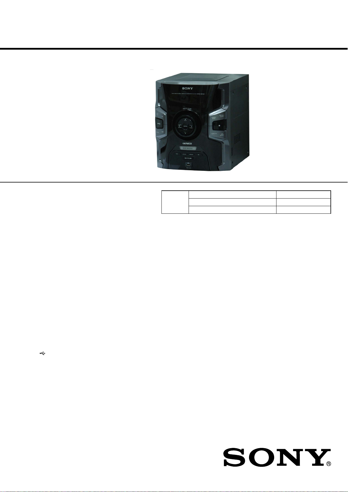
Sony MHC-GPX3, HCD-GPX3G Schematic
Ver. 1.0 2012.04
• HCD-GPX3G is the amplifi er, USB, CD player
and tuner section in MHC-GPX3.
HCD-GPX3G
E Model
• “WALKMAN” and “WALKMAN” logo are registered trademarks of
Sony Corporation.
• MPEG Layer-3 audio coding technology and patents licensed from
Fraunhofer IIS and Thomson.
• Windows Media is either a registered trademark or trademark of Microsoft
Corporation in the United States and/or other countries.
• This product contains technology subject to certain intellectual property
rights of Microsoft.
Use or distribution of this technology outside of this product is prohibited
without the appropriate license(s) from Microsoft.
Amplifi er section
The following are measured at
Mexican model:
AC 120 V – 240 V, 60 Hz
Other models:
AC 120 V – 240 V, 50/60 Hz
MHC-GPX3
Front speaker
Power Output (rated):
300 W + 300 W (at 4 ohms, 1 kHz,
1% THD)
RMS output power (reference):
475 W + 475 W (per channel at
4 ohms, 1 kHz)
Inputs
TV/DVD/SAT (AUDIO IN) L/R
Voltage 1.2 V, impedance 47 kilohms
PC/GAME (AUDIO IN) L/R
Voltage 1.2 V, impedance 47 kilohms
(USB) port: Type A
USB section
Supported bit rate
MP3 (MPEG 1 Audio Layer-3):
32 kbps – 320 kbps, VBR
WMA: 48 kbps – 192 kbps
AAC: 48 kbps – 320 kbps
Sampling frequencies
MP3 (MPEG 1 Audio Layer-3):
32 kHz/44.1 kHz/48 kHz
WMA: 44.1 kHz
AAC: 44.1 kHz
Supported USB device
Mass Storage Class
Maximum current
500 mA
Disc player section
System
Compact disc and digital audio system
Laser Diode Properties
Emission Duration: Continuous
Laser Output*: Less than 44.6 μW
* This output is the value measurement
at a distance of 200 mm from the
objective lens surface on the Optical
Pick-up Block with 7 mm aperture.
Frequency response
20 Hz – 20 kHz
Signal-to-noise ratio
More than 90 dB
Dynamic range
More than 88 dB
Tuner section
FM stereo, FM/AM superheterodyne tuner
Antenna:
FM lead antenna
AM loop antenna
FM tuner section
Tuning range
87.5 MHz – 108.0 MHz (100 kHz
step)
Model Name Using Similar Mechanism HCD-EX66/EX88/EX99
CD Section
Mechanism Type CDM76B-D1BD76
Optical Pick-up Block Name DA11MMVGP
SPECIFICATIONS
AM tuner section
Tuning range
Pan American models:
530 kHz – 1,710 kHz (10 kHz step)
531 kHz – 1,710 kHz (9 kHz step)
Other models:
530 kHz – 1,610 kHz (10 kHz step)
531 kHz – 1,602 kHz (9 kHz step)
General
Power requirements
Mexican model: AC 120 V – 240 V, 60 Hz
Other models: AC 120 V – 240 V, 50/60 Hz
Power consumption
180 W
Dimensions (w/h/d) (excl. speakers)
(Approx.)
280 mm × 335 mm × 440 mm
Mass (excl. speakers) (Approx.)
6.0 kg
Supplied accessories
Remote control (1)
R6 (Size AA) batteries (2)
FM lead/AM loop antenna (1)
Design and specifi cations are subject to
change without notice.
9-890-598-01
2012D08-1
2012.04
©
COMPACT DISC RECEIVER
Sony Corporation
Published by Sony EMCS (Malaysia) PG Tec
HCD-GPX3G
Notas sobre reparo do componentes do tipo Chip
• Nunca reutilize um componente tipo chip.
• Informamos que o lado menos dos capacitores de tantalo podem ser
danificados se expostos a altas temperaturas.
5E3$5$(03/$&$6'(&,5&8,72)/(;Ë9(/
• Manter a temperatura do ferro de soldar
durante o reparo.
• Não toque com o ferro de soldar o mesmo condutor chip da
placa (mais de 3 vezes).
• Tenha cuidado para não aplicar
soldar ou dessoldar.
ATENÇÃO
O uso dos controles justes
procedimentos a exceção para
isto radiatição perigosa.
resultar na exposição de
daqueles especificados
Este aparelho é classificado como produto
LASER CLASSE 1. Esta etiqueta está
localizada na parte traseira.
dos ou a ou o desempenho
$7(1d2&2026&20321(17(6'(6(*85$1d$!
OS COMPONENTES IDENTIFICADOS COM A MARCA 0
NOS DIAGRAMAS ESQUEMÃTICOS E NA LISTA DE PEÇAS SÃO
CRÍTICOS PARA SEGURANÇA. SOMENTE OS SUBSTITUA POR
PEÇAS NUMERICAMENTE IDENTIFICADAS NESSE MANUAL
OUEM SUPLEMENTOS PUBLICADOS PELA SONY.
2

Ë1',&(
HCD-GPX3G
1. 1OT$S'(6(9,d2 ............................................. 4
2. D(60217$*(0
2-1. Tampa Lado (L), Tampa Lado (R) ................................ 10
2-2. Seção Painel Superior .................................................... 11
2-3. Seção Painel Frontal........................................................ 12
2-4. Placa 2CH DAMP ........................................................... 12
2-5. Seção Painel Traseiro e Chassi ....................................... 13
2-6. Mecanismo CD ............................................................... 13
2-7. Unidade Base .............................................................. 14
2-8. Unidade Ótica ................................................................ 14
3. 02'2 7E67( .......................................................... 15
4. 9(5,),&$d2(/e75,&$.......... ........................ 17
5. DIAGRAM$S
5-1. Diagrama em bloco – Seção CD/USB – ........................ 19
5-2. Diagrama em bloco – Seção MAIN – ............................ 20
5-3. Diagrama em bloco – Seção Display/Fonte de Alimentação ...21
5-4. Placa de circuito Impresso – Placa DISPLAY – ............. 23
5-5. Diagrama Esquemático – Placa DISPLAY (1/2) – ......... 24
5-6. Diagrama Esquemático – Placa DISPLAY (2/2) – ........ 25
5-7. Placa de circuito Impresso – Placa BD76 – ................... 26
5-8. Diagrama Esquemático – Placa BD76 (1/2) – ............... 27
5-9. Diagrama Esquemático – Placa BD76 (2/2) – ............... 28
5-10. Placa de circuito Impresso –
Placa 2CH DAMP (Lado Componente) – ...................... 29
5-11. Placa de circuito Impresso –
Placa 2CH DAMP (Lado Cobreado) – ........................... 30
5-12. Diagrama Esquemático – Placa 2CH DAMP (1/2) – ..... 31
5-13. Diagrama Esquemático – Placa 2CH DAMP (2/2) – ..... 32
5-14. Placa de circuito Impresso – Placas VOLUME e USB –.. 33
5-15. Diagrama Esquemático – Placas VOLUME e USB – ... 34
5-16. Placa de circuito Impresso – Placa TUNER1AM3R – ... 35
5-17. Diagrama Esquemático – Placa TUNER1AM3R – ........ 36
5-18. Diagrama Esquemático - Placa SMPS 3H385W -. ......... 37-1
6. 9,67$EXPLOD,'$
6-1. Seção Aparelho ........................................................... 45
6-2. Seção Painel Frontal....................................................... 46
6-3. Seção Painel Superior..................................................... 47
6-4. Seção Painel Traseiro...................................................... 48
6-5. Seção Chassi ................................................................... 49
7. /,67$'(3(d$6ELeTRICA6 ........................ 50
&$,;$$&Ò67,&$
CAIXA ACÚSTICA - SS-GPX3
VISTA EXPLODIDA - SS-GPX3............................................
LISTA DE PEÇAS ELÉTRICAS ............................................
61
62
3
HCD-GPX3G
SEÇÃO 1
NOTAS DE SERVIÇO
NOTAS SOBRE O MANUSEIO DA BLOCO DE
UNIDADE ÏTICA OU UNIDADE BASE
O diodo laser da unidade optica é sensível a descargas eletroestáticas
podendo vir a ser danificado por descargas causadas por roupas
ou mesmo pelo corpo humano. Durante o reparo tenha cuidado para não causar danos a unidade, devido a cargas eletroestáticas e siga
corretamente os procedimentos descritos nesse manual para a execução de reparos e troca de componentes.
As placas de circuito impresso flexíveis sao facilmente danificadas
Tenha cuidado ao manuseá-las.
NOTAS SOBRE A EMISSÃO DO DIODO LASER
O feixe laser nesse modelo é concentrado de forma a ser
superfície reflexiva do disco, pela lente objetiva da unidade óptica.
Quando observar a emissão do diodo laser, tome o cuidado de estar
no mínimo a 30 cm da lente objetiva.5
SOLDA SEM CHUMBO
Placas que exigem o uso de solda sem chumbo são impressas com
a marca LF (lead free) indicando que a solda não contém chumbo.
(Atenção: Algumas placas de circuito impresso não podem ter essa
marca devido ao seu tamanho reduzido.)
: IDENTIFICAÇÃO DA SOLDA SEM CHUMBO
A solda livre de chumbo tem as seguintes características:
• Derrete a uma temperatura 40 °C maior que a solda comum.
Ferros de solda comuns podem ser usados mas a ponta tem que
ser aplicada por um tempo maior.
Ferros de solda com regulagem de temperatura devem ser ajusta-
do no valor de 350 °C.
Atenção: A impressao da placa (trilhas de cobre) pode se sol-
tar se a ponta permanecer por muito tempo. Tenha cuidado!
• É mais viscosa
A solda livre de chumbo é mais viscosa (flui com menor faci-
lidade) que a solda comum, portanto tenha cuidado com as
pontes de solda, especialmente entre os pinos de IC's.
• Pode ser utilizada com solda comum
É melhor usar apenas solda sem chumbo mas este tipo também
pode ser adicionado a solda comum.
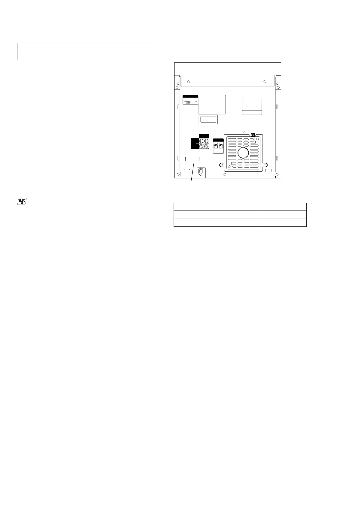
,DENTIFICAd2'(02'(/2
– 3DLQHO7UDVHLUR –
ANTENNA
FM/AM
.
TV/
PC/
DVD/
GAME
SAT
FRONT SPEAKERS
L
AUDIO
IN
R
Parts No.
HCD-GPX3G: E2, E51%5
HCD-GPX3G: MX
• Abbreviation
E2 : 120V AC area in E model
E51 : Chilean and Peruvian models
MX : Mexican model
BR : Modelo Brasil
R
L
IMPEDANCE
USE 4
ModelR Part No.
4-411-594-0[]
4-411-594-1[]
RE$LI6$5 275$9$0(172'$ %$1'(-$'2',6&2
A função de travamento da bandeja do disco deve ser utilizada
para evitar o roubo do disco em lojas de departamento.
ReDliVDQGRR ProcedLPHQWR:
1. Pressionar o botão [I/
STANDBY] para ligar o aparelho.
1
2. Pressionar o botão [CD/DISC SKIP] para selecionar a função CD.
3. Manter pressionado o botão [x], e pressionar o botão [ENTER] por
mais 5 segundos).
4. A menssagem “LOCKED” aparece no display e a bandeja de disco esta
travada.
5. Para destravar, manter pressionado o botão [x], e pressionar o botão [ENTER] por
mais 5 segundos).
6. A menssagem “UNLOCKED” aparece no display e a bandeja de disco esta
destravada.
4XDQGR o botão [I/
NotD:
tDPEpPpGHVDWLYDGD
STANDBY] IRUSUHVVLRQDGRDIXQomR/2&.('
1
4
3OSId2'(6(59,d2 '2 CDM76
HCD-GPX3G
PLACA BD76
326,d2'(6(59,d2 '$6 3/$&$6
base
Placa PANEL
Placa USB
Placa 2CH DAMP
base
Placa SMPS 3H385W
5
HCD-GPX3G
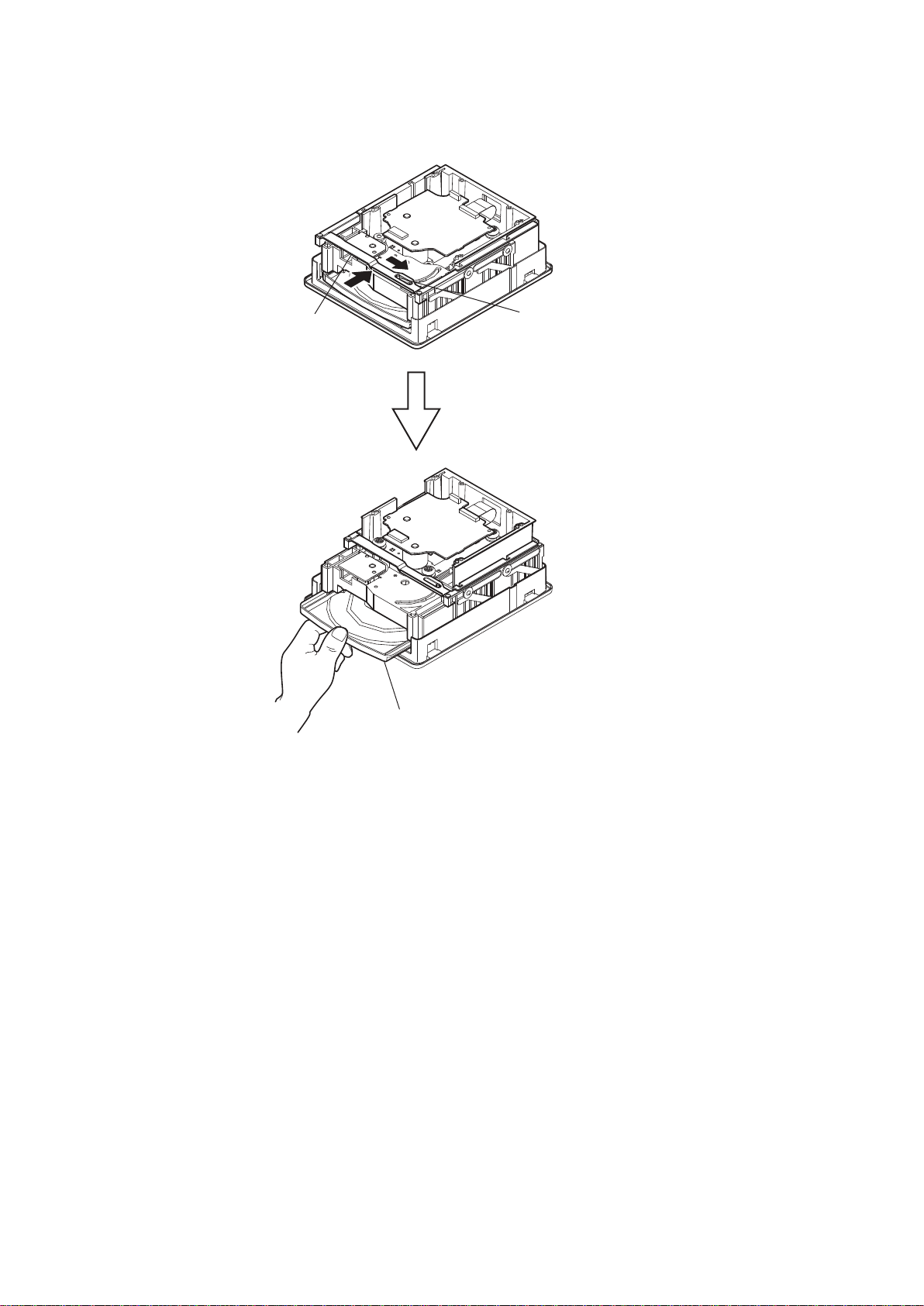
&202$%5,5 $%$1'(-$48$1'22$3$5(/+2(67,9(5'(6/,*$'2
VXSRUWH
pinR
Pu[DU DEDQGHMD FRPDPmR.
6
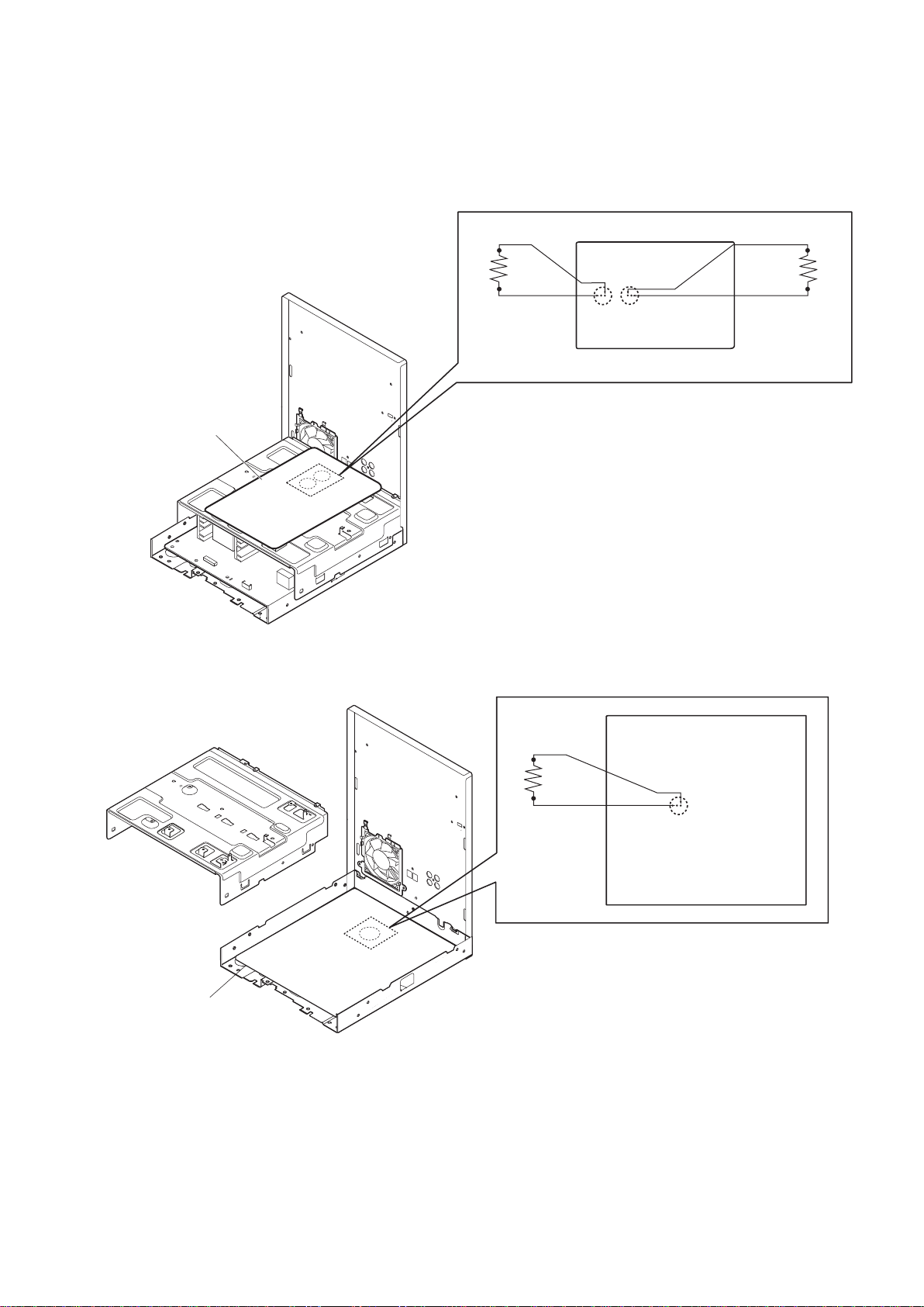
'(6&$55(*$5CAPACITOR3$5$ 35(9(1,5&+248(ELeTRICO
HCD-GPX3G
Antes de verificar a placa &H DAMP, fazer a
descarga dos capacitores C14H C143
para prevenir choque elétrico.
3laca&+'$03
:
C1431
Antes de verificar a placa 6036ID]HUD
descarga do capacitor CSDUD
prevenir choque elétrico.
&
:
3ODFD6036
:
&
7
HCD-GPX3G
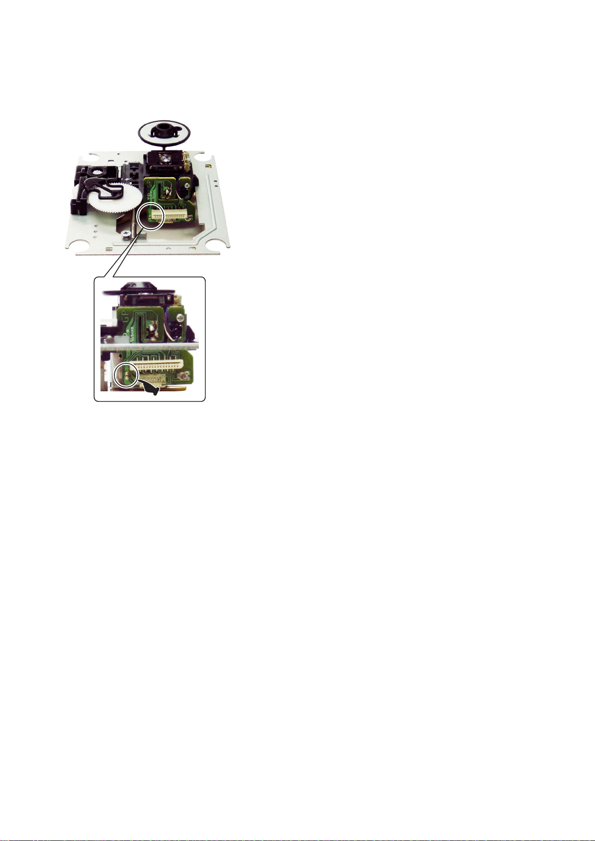
PRECA8d2 48$1'2,167$/$5 A N29$ 81,'$'(Ï7,&$/
PRECAUd2 &20(/(75,&,'$'((67È7,&$$17(6'(5(029(52&8572'(62/'$
4XDQGRLQVWDODUDQRYDXQLGDGHyWLFDHODGHYHVHUconectDGDSULPHLUR
DSODFDGHFLUFXLWRLPSUHVVRDQWHVGHUHPRYHURFXUWRGHVROGD
3DUDSUHYHQLUGDQRVFDXVDGRVSHODHOHWULFLGDGHHstiticD.
(1mRGHPRUHPXLWRWHPSRUHPRYHQGRRFXUWRGHVROGDGDXQLGDGHyWLFD
(Não remova o curto de solda a unidade ótica não estiver conectada a
placa de circuito impresso.)
8
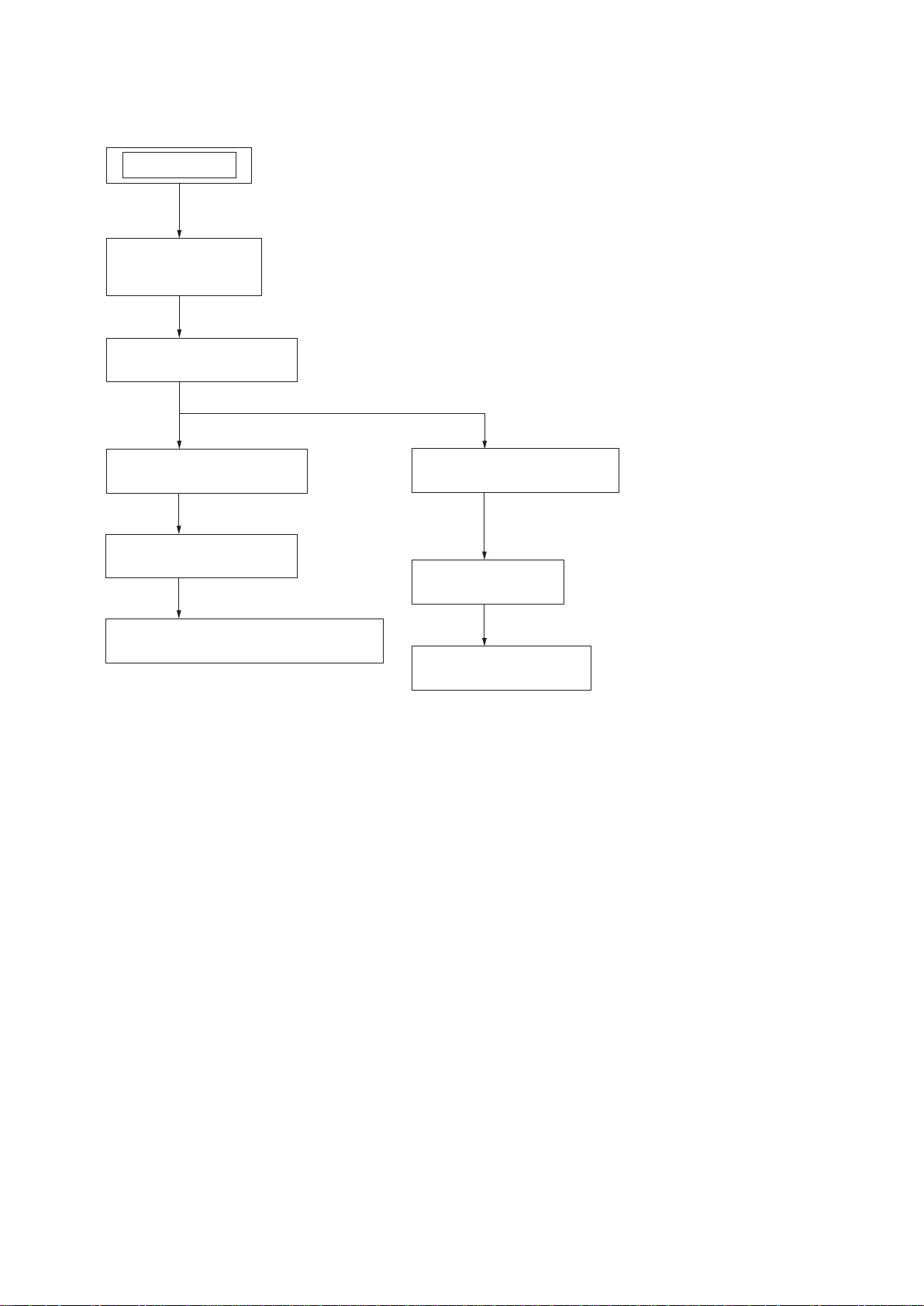
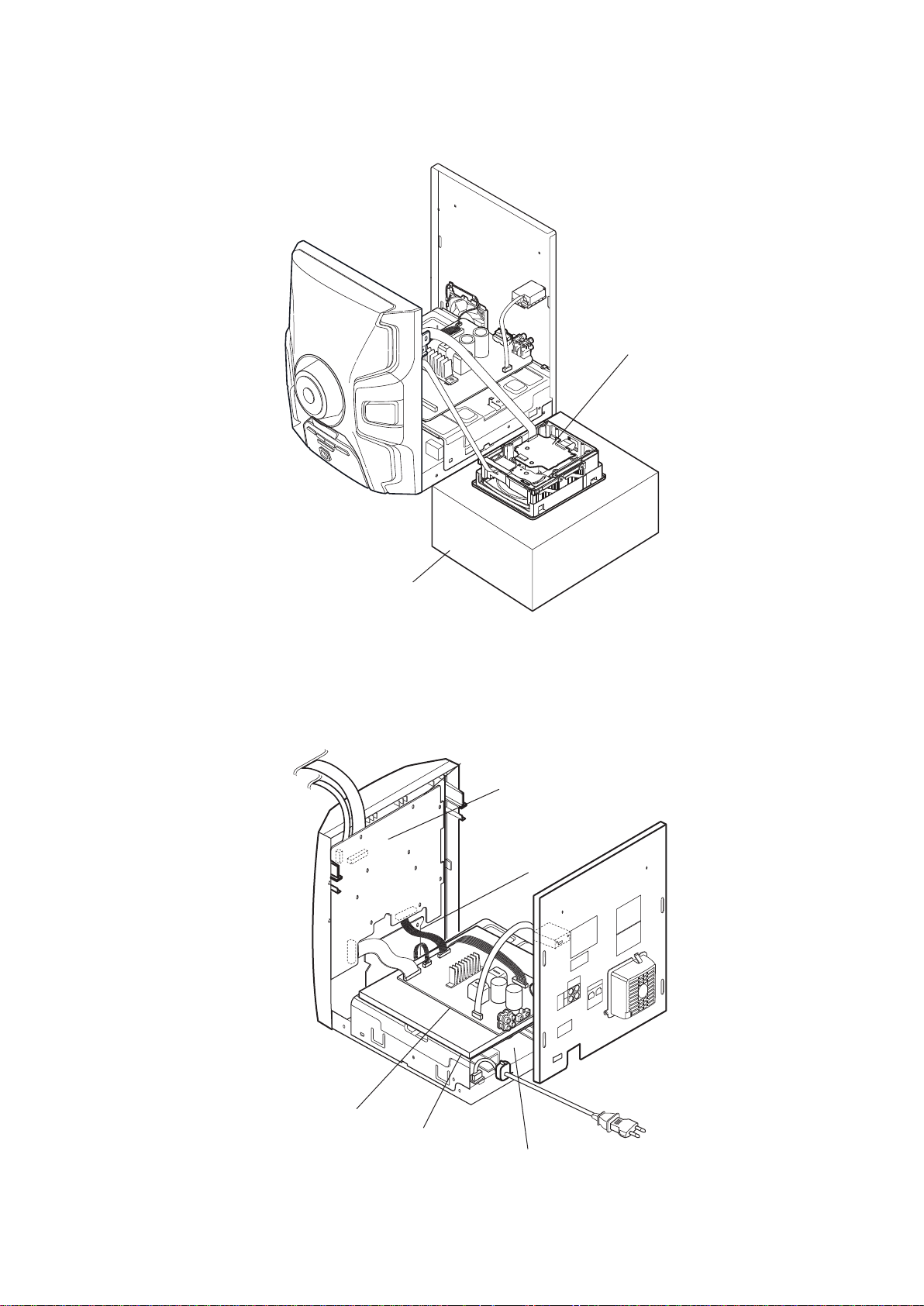
DE6M217$*(0
• This set can be disassembled in the order shown below.
SET
2-1. SIDE CASE (L),
SIDE CASE (R)
(Page 10)
2-2. TOP PANEL SECTION
(Page 11)
HCD-GPX3G
SEd2 2
2-3. FRONT PANEL SECTION
(Page 12)
2-4. 2CH DAMP BOARD
(Page 12)
2-5. BACK PANEL SECTION AND CHASSIS
(Page 13)
2-6. CD MECHANISM DECK
(Page 13)
2-7. BASE UNIT
(Page 14)
2-8. OPTICAL PICK-UP
(Page 14)
9
HCD-GPX3G
Note: Follow the disassembly procedure in the numerical order given.
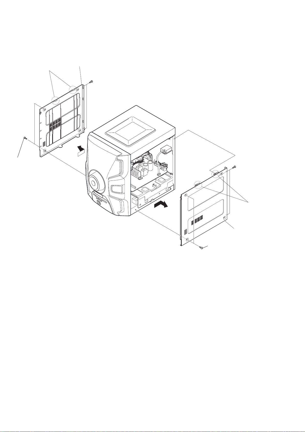
2-1. 7$03$/$'2 (L), 7$03$/$'2 (R)
two claws
1 two screws
(+BVTP 3 x 14)
4 side case (L)
2 two screws
(+BVTP 3 x 14)
3
6 two screws
(+BVTP 3 x 14)
two claws
7
8 side case (R)
5
two screws
(+BVTP 3x14)
10
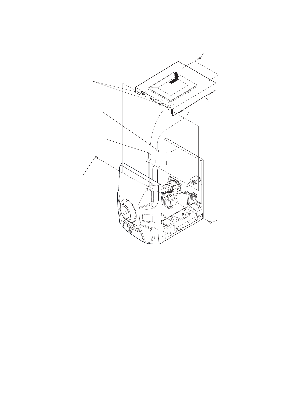
2-2. 6(d2PA,NEL 683(5,25
two hooks
HCD-GPX3G
5 two screws
(+BVTP 3 x 14)
6
1 wire (flat type)
(21core)(CN401)
2 wire (flat type)
(5core)(CN001)
3 one screw
(+BVTP 3 x 8)
7 top panel section
4
one screw
(+BVTP 3 x 8)
11
HCD-GPX3G
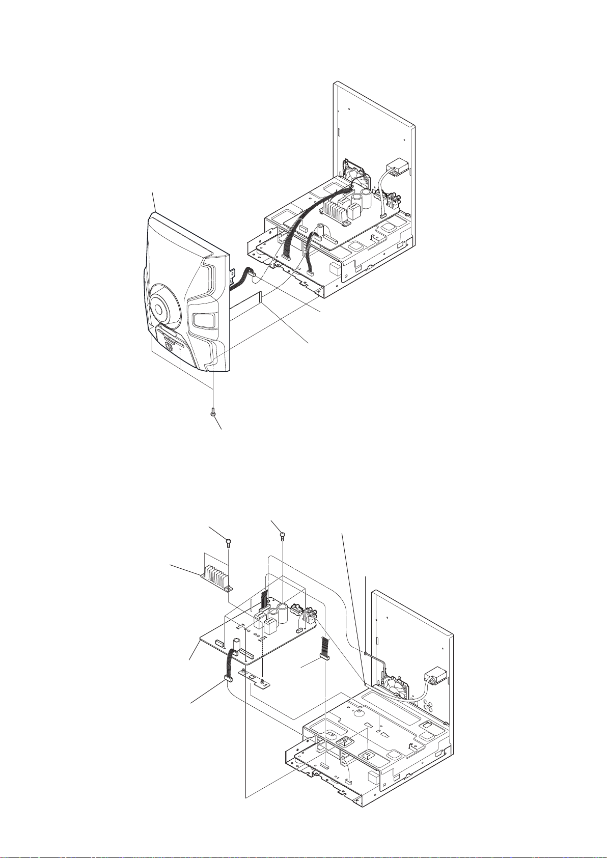
2-3. FRONT PANEL SECTION
4 front panel section
2
CN801 (7P)
2-4. 3/$&$2CH DAMP
7 HEAT SINK (2CH)
6 two screws
(+PTPWH 2.6XL)
1 three screws
(BVTP 3 x 8)
1 four screws
(BVTP 3 x 8)
3
wire (flat type) (25core)(CN803)
4 wire (flat type)(9core)(CN805)
5 CN1405(3P)
12
8 2CH DAMP board
3 CN3(5P)
2 CN2(9P)
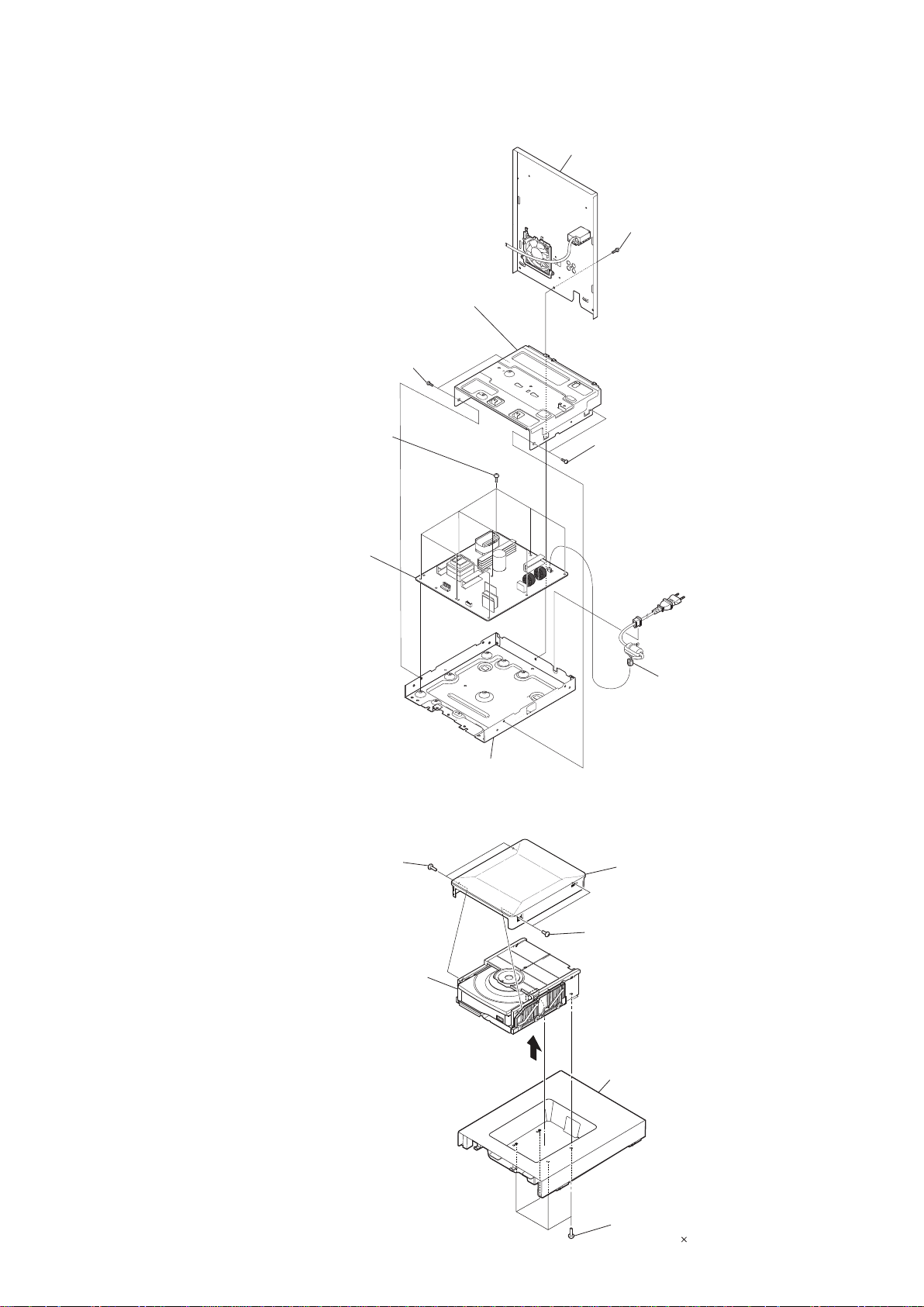
2-5. 6(d2PA,NEL75$6(,52( CHASSI
5
bracket, SMPS (shield)
3 two screws
(BVTP 3 x 8)
6 nine screws
PWH 3 x 8 (SUMITITE)
2
back panel section
1
one screws
(BVTP 3 x 8)
4
two screws
(BVTP 3 x 8)
HCD-GPX3G
2-6. MECANISM2 &D
REGULATOR,
7
SWTCHING board
4 two screws
(+P tapping (B2.6))
CD mechanism deck block
6
9
chassis
8 CN1 (2P)
top lid
5
4 two screws
(+P tapping (B2.6))
2
top panel
3
1 four screws
(+BVTP 3
10)
13
HCD-GPX3G
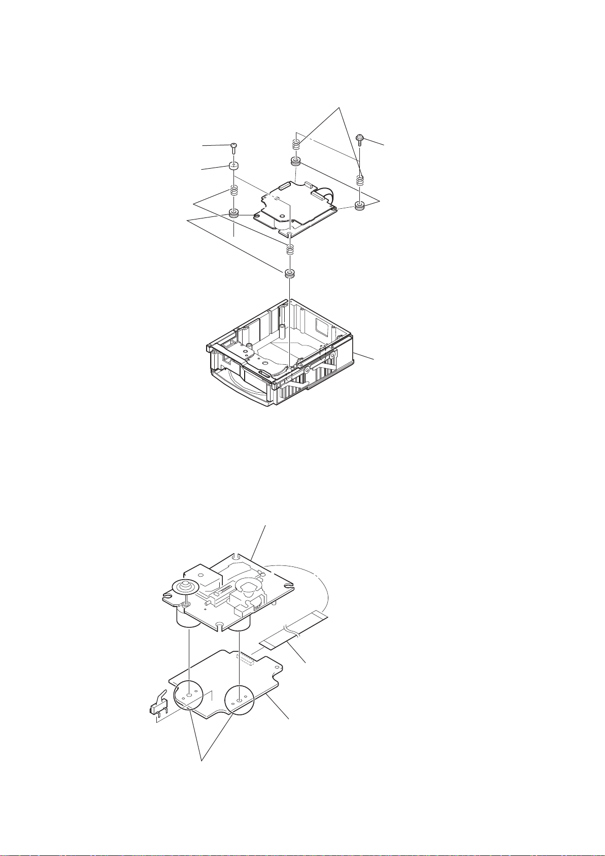
2-7. 81,'$'(BASE
2 two screws
(+BVTP 2.6 (3CR))
3
two coil springs (insulator)
4
5
two stoppers (BU)
two insulators
two coil springs (insulator)
4
1 two floating screws
(+PTPWH M2.6)
two insulators
5
2-8. 81,'$'(ÏTICA
6 CD MECHANISM DECK
3 optical pick-up
14
Remove the four solders.
1
2 wire (flat type) (16 core)
(CN201)
4 BD76 board

SEd2 3
02'2'(TESTE
HCD-GPX3G
[PANEL TEST MODE]
• This mode is used to check the fl uorescent indicator tube,
LEDs, keys, [MASTER VOLUME] jog, model, destination and software version.
• Procedure:
1. Press [CD] button and [TUNER/BAND] button simultaneously and hold 3 seconds.
2. All LEDs and segments in fl uorescent indicator tube are
lighted up.
3. When you want to enter to the software version display
mode, press [
appears on the fl uorescent indicator tube.
• “GPX 0” is shown for MHC-GPX3.
Press [
information.
4. During the destination information display
/ ] button. Each time [
fl uorescent indicator tube shows the version of each
category software in the following sequence: SC, UI, PF,
SYS, CD, MM, ST
information display.
5. When [OPTION] button is pressed while the version
numbers are being displayed except model and destination,
the date of the software creation appears. When [OPTION]
button is pressed again, the display returns to the software
version display.
6. Press [
7. In the key check mode, the fl
displays “K 0 V0”.
Each time a button is pressed, “K” value increases. How-
ever, once a button has been pressed, it is no longer taken
into account.
“V” value increases in the manner of 0,1, 2, 3 ... if [MAS-
TER VOLUME] knob is turned clockwise, or it decreases
in the manner of 0, 9, 8,7 ... if [MASTER VOLUME]
knob is turned counterclockwise.
8. When [ENTER] button is pressed after all LEDs and
segments in fl uorescent indicator tube light up, alternate
segments in fl uorescent indicator tube and LEDs would
light up. If you press [ENTER] button again, another half
of alternate segments in fl uorescent indicator tube and
LEDs would light up. Pressing [ENTER] button again
would cause all segments in fl uorescent indicator tube and
LEDs light up.
9. To release from this mode, press three buttons in the same
manner as step 1, or disconnect the power cord.
/ ] button. The model information
+
/ ] button again to view the destination
+
, press [
/ ] button is pressed, the
+
, TA, TM and return back to model
/ ↓]button, the key check mode is activated.
+
uorescent indicator tube
[COMMON TEST MODE]
• This mode is used to check operations of the Amplifi er
section.
• Procedure:
• To enter Common Test Mode
1. Press [USB] button and [BASS BAZUCA] button simultaneously and hold for 3 seconds.
2. The function is changed to TV and the volume is changed
to VOLUME MIN.
• Check of Amplifi er
1. Press [ROCK] button repeatedly until a message “GEQ
MAX” appears on the fl uorescent indicator tube. GEQ
increases to its maximum.
2. Press [ROCK] button repeatedly until a message “GEQ
MIN” appears on the fl uorescent indicator tube. GEQ
decreases to its minimum.
3. Press [ROCK] button repeatedly until a message “GEQ
FLAT” appears on the fl uorescent indicator tube. GEQ is
set to fl at.
4. When the [MASTER VOLUME] knob is turned clockwise
even slightly, the sound volume increases to its maximum
and a message “VOLUME MAX” appears on the fl uores-
cent indicator tube.
5. When the [MASTER VOLUME] knob is turned counterclockwise even slightly, the sound volume decreases to its
minimum and a message “VOLUME MIN” appears on the
fl uorescent indicator tube.
• To release from Common Test mode
1. To release from this mode, press [
2. The cold reset is enforced at the same time.
I/1 STANDBY] button.
[USER RESET]
• The user reset clears all data including preset data stored
in the data fl ash to initial conditions exclude history mode
+
data
• Procedure:
1. Press [
2.
3. “RESET” appears on the fl uorescent indicator tube.
After that, the fl uorescent indicator tube becomes blank for
I/1 STANDBY] button to turn on the system.
Press [x] button and
for 3 seconds.
a while, and the system is reset.
[I/
STANDBY]
1
button simultaneously
[COLD RESET]
• The cold reset clears all data including preset data stored in
the data fl ash to initial conditions. Execute this mode when
returning the set to the customer.
• Procedure:
1. Press [
2. Press [ENTER] button and [EQ] button simultaneously for
3. “COLD RESET” appears on the fl uorescent indicator tube.
I/1 STANDBY] button to turn on the system.
3 seconds.
After that, the fl uorescent indicator tube becomes blank for
a while, and the system is reset.
[TUNER STEP CHANGE]
• The step interval of AM channels can be toggled between
9 kHz and 10 kHz. This mode is not available for Saudi
Arabian, European and Russian models.
• Procedure:
1. Press [
2. Press [TUNER/BAND] button repeatedly to select the
3. Press [
4. Press [LED EFFECT] button and [
button simultaneously. The system turns on automatically.
appears on the fl uorescent indicator tube and thus the
I/1 STANDBY] button to turn on the system.
“AM”.
I/1 STANDBY] button to turn off the system.
I/1 STANDBY]
The message “AM 9K STEP” or “AM 10K STEP”
channel step is changed.
[CD TRAY LOCK MODE]
• This mode let you lock the disc tray. When this mode is
activated, the disc tray will not open when [OPEN/CLOSE]
button or [EX-CHANGE] button is pressed. The message
“LOCKED” will be displayed on the fl uorescent indicator
tube. This mode only applied when there is disc(s) on the tray.
• Procedure:
1. Press [
2. Select CD function.
3. Press [
hold down until “LOCKED” or “UNLOCKED” displayed
on the fl uorescent indicator tube (around 5 seconds).
I/1 STANDBY] button to turn on the system.
] button and [ENTER] button simultaneously and
x
15
HCD-GPX3G
[FACTORY PRESET]
• This mode is use to load all the factory use preset frequencies
into FM 1-FM 20 and AM 1-AM 10. Originally, frequency
of FM 1-FM 20 and AM 1-AM10 are set to the minimum
frequency.
• Procedure:
1. Press [
I/1 STANDBY] button to turn on the system.
2. Press [CD] button and [AUDIO IN] button simultaneously
and hold for 3 seconds, message “FACTORY” appears on
the fl uorescent indicator tube. The function is changed to
TUNER automatically.
[CDM AGING MODE]
• This mode is used to display the total count of meter pointer touch initial switch and max switch.
• Procedure:
1. Press [
I/1 STANDBY] button to turn on the system.
2. Select CD function and All DISC play mode
3. Put disc on all tray.
4. Press [
/ ] button and [
+
] button simultaneously for 3
x
seconds.
5. The fl uorescent indicator tube displays Aging
Display “AG xxxx/yyyy”.
“xxxx” represents the error counter
(Maximum Value of “xxxx” = 9999)
“yyyyy” represents the cycle counter
(Maximum Value of “yyyy” = 9999)
6. Press [<<] or [>>] to search for Aging History
Error Display
The fl uorescent indicator tube displays
“Mx E1E2E3E4”.
x: error history number
E1: Loading sequence JCP high
E2: Loading sequence JCP low
E3: Loading operation JCP
E4: Cam position operation JCP
7. Press [ENTER] to Aging Display
• To release from Meter Aging Mode.
To release from this mode, press [
I/1 STANDBY] button or
perform COLD RESET operation.
[HISTORY MODE]
• This mode is used to check important data stored in the
system when PROTECTOR happen.
• Procedure:
1. During demo mode, press [
BAZUCA] for 5 seconds to mode in to history mode.
2. Press the [TUNING +] or [TUNING -] button to check
history data stored
Item Display
Protector Count
PROCOUNT
Protector Type P R O T Y P E
Single Power On
Time
Total Power On
Time
T1 H M
T2
Input Function F U N C
Volume V O L
Actual
Attenuation
ATT
Low EQ Level E Q L O W
Mid EQ Level E Q M I D
High EQ Level E Q H I G H
u] button and [BASS
H M
VACS Level V A C S
AP VACS Level A P V A C S
Surround Setting S U R R
Bass Bazuca
Setting
BAZUCA
• To release from History Mode.
To release from this mode, press [
I/1 STANDBY] button.
[PROTECT KIND CHECK TEST MODE]
• This mode is used to check types of protect occurred during
protector on.
• Procedure:
3. During protection on, fl uorescent indicator tube shows
blinking message “PROTECT EXX”.
“EXX” – represent the error code.
4. Press [
u] button & [
5. Fluorescent indicator tube display will toggle between
“PROTECT” message & protector kind message display.
Bellow table explains on protector kind.
Error Code Protector Message Description
E01 "AMP OCP"
E02 "MTK POWER" No power supply to DMB mount
E03 "POWER SUPPLY" Defect of power supply circuit to AMP
E04 "AMPLIFIER" Defect of AMP circuit
E06 “FAN BLOCK”
• To release from this mode.
Press [
u] button & [
unplug & re-plug in the power cord.
1. Defect of AMP circuit
1-1. If PROTECT mode is “AMPLIFIER”,
The following defect might be possible.
Defects Possible cause
OTP (Over Tempera-
ture Protection)
DC Detection
Unusual output of
Power mount
1-2. If speaker does not have output even if the set status
is not in PROTECT mode
The following defect might be possible.
Defects Possible cause
Under Voltage IC1402 output is below 12V.
RESET defect Reset signal status from micom is not ‘H’ .
2. Defect of power supply circuit to AMP
2-1. If the PROTECT mode is “POWER SUPPLY”,
There is possibility of unusual power supply of any of the
AMP IC or Pre-amplifi er.
• To release from this mode.
Press [
u] button and [
or unplug and re-plug in the power cord.
] button simultaneously.
x
The overcurrent condition to MOSFET occurs by defect of MOSFET or
defect of PS output line.
Defect of DC FAN and DC FAN
driver circuit
] button simultaneously again or
x
Unusual heat up of MOSFET by improper assembly of heatsink, destruction
of MOSFET etc..
DC appears in SP terminal by defect of
AMP IC and MOSFET or output is shortcircuit.
The power mount has unusual output.
] button simultaneously again
x
16
SEd2 4
9(5,),&$d2ELeTRIC$
HCD-GPX3G
CD SECTION
Note:
1. CD Block is basically constructed to operate without adjustment.
2. Use YEDS-18 disc (Part No. 3-702-101-01) unless otherwise indicated.
3. Use an oscilloscope with more than 10 M impedance.
4. Clean the object lens by an applicator with neutral detergent when the
signal level is low than specifi ed value with the following checks.
5. Check the focus bias check when optical pick-up block is replaced.
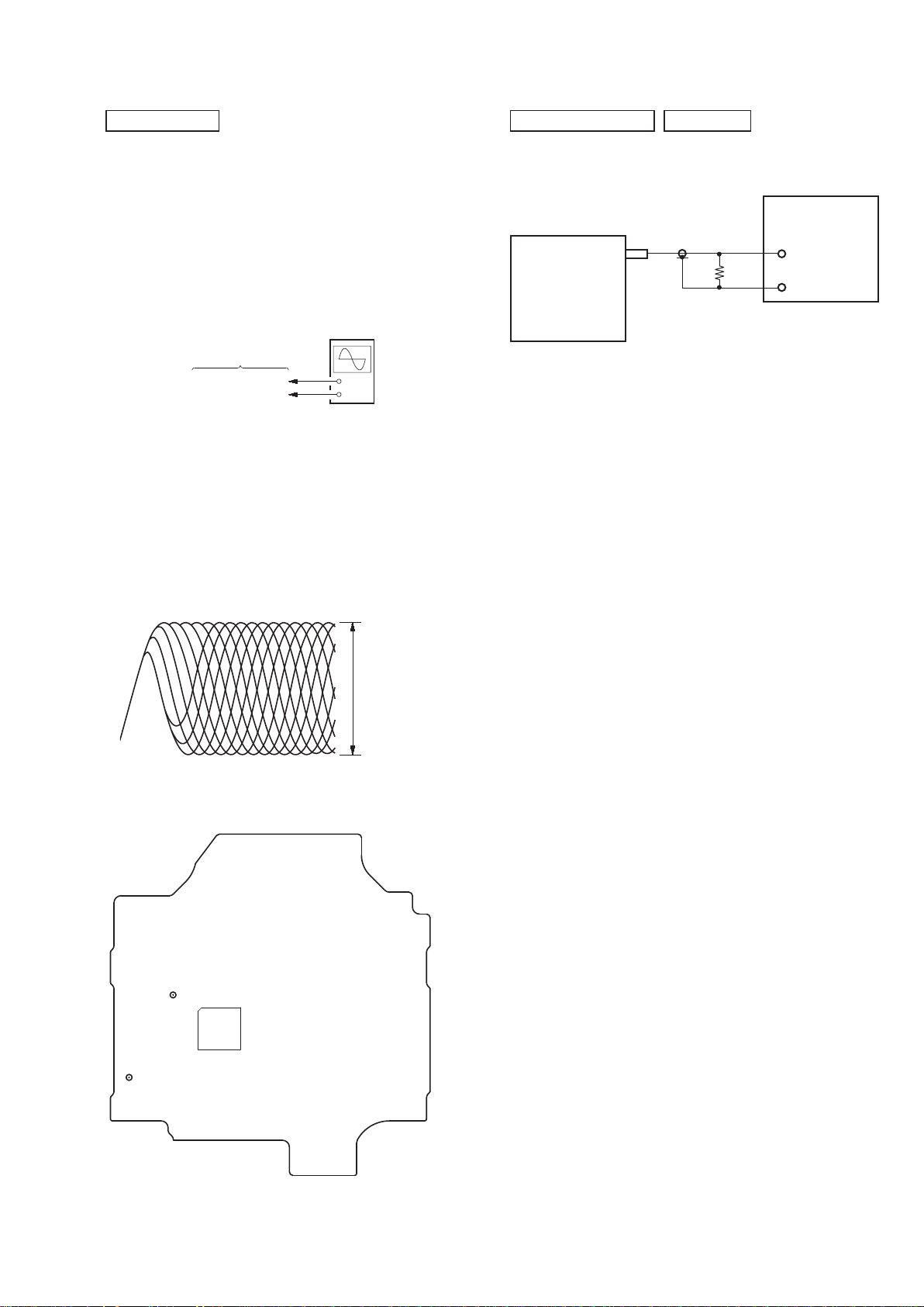
FOCUS BIAS CHECK
oscilloscope
(DC range)
BD76 board
CL102 (RFOUT)
CL117 (VREF)
Procedure:
1. Connect the oscilloscope to CL102 (RFOUT) and CL117
(VREF) on the BD76 board.
2. Press the [
] button to turn the power on, and press the [CD]
?/1
button to select CD function.
3. Set disc (YEDS-18) and press the [
4. Confi rm that oscilloscope waveform is as shown in the fi gure
below (eye pattern).
A good eye pattern means that the diamond shape (◊) in the
center of the waveform can be clearly distinguished.
+
–
] button to playback.
u
VOLT/DIV: 200 mV
TIME/DIV: 500 ns
TUNER SECTION
0 dB = 1 V
FM AUTO STOP CHECK
signal
generator
set
+
75 :
–
Procedure:
1. Turn the power on.
2. Input the following signal from Signal Generator to FM antenna input directly.
Carrier frequency : A = 87.5 MHz, B = 98 MHz, C = 108 MHz
Deviation : 75 kHz
Modulation : 1 kHz
ANT input : 35 dBu (EMF)
Note: Please use 75 ohm “coaxial cable” to connect SG and the set. You
cannot use video cable for checking.
Please use SG whose output impedance is 75 ohm.
3. Set to FM tuner function and scan the input FM signal with
automatic scanning.
4. Confi rm that input Frequency of A, B and C detected and auto-
matic scanning stops.
Checking Location:
– BD76 Board (Side B) –
CL102
(RFOUT)
IC101
CL117
(VREF)
level:
1.1 ± 0.4 Vp-p
The stop of automatic scanning means “The station signal is received in good condition”.
17
HCD-GPX3G
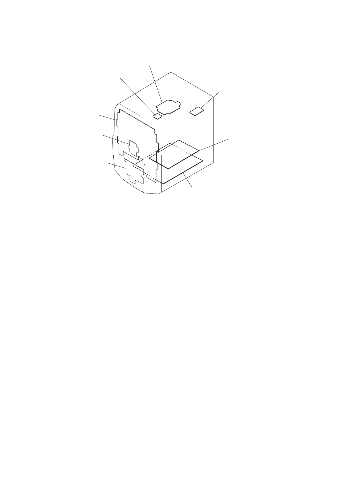
• /RFDOL]DomRGDVSODFDV
3ODFDDISPLAY
SEd2 5
DIAGRAM$S
3ODFDBD76
3ODFDLOADING
3ODFDTUNER1AM3R
3ODFDVOLUME
3ODFDUSB
3ODFD2CH DAMP
3ODFDS036+:
18
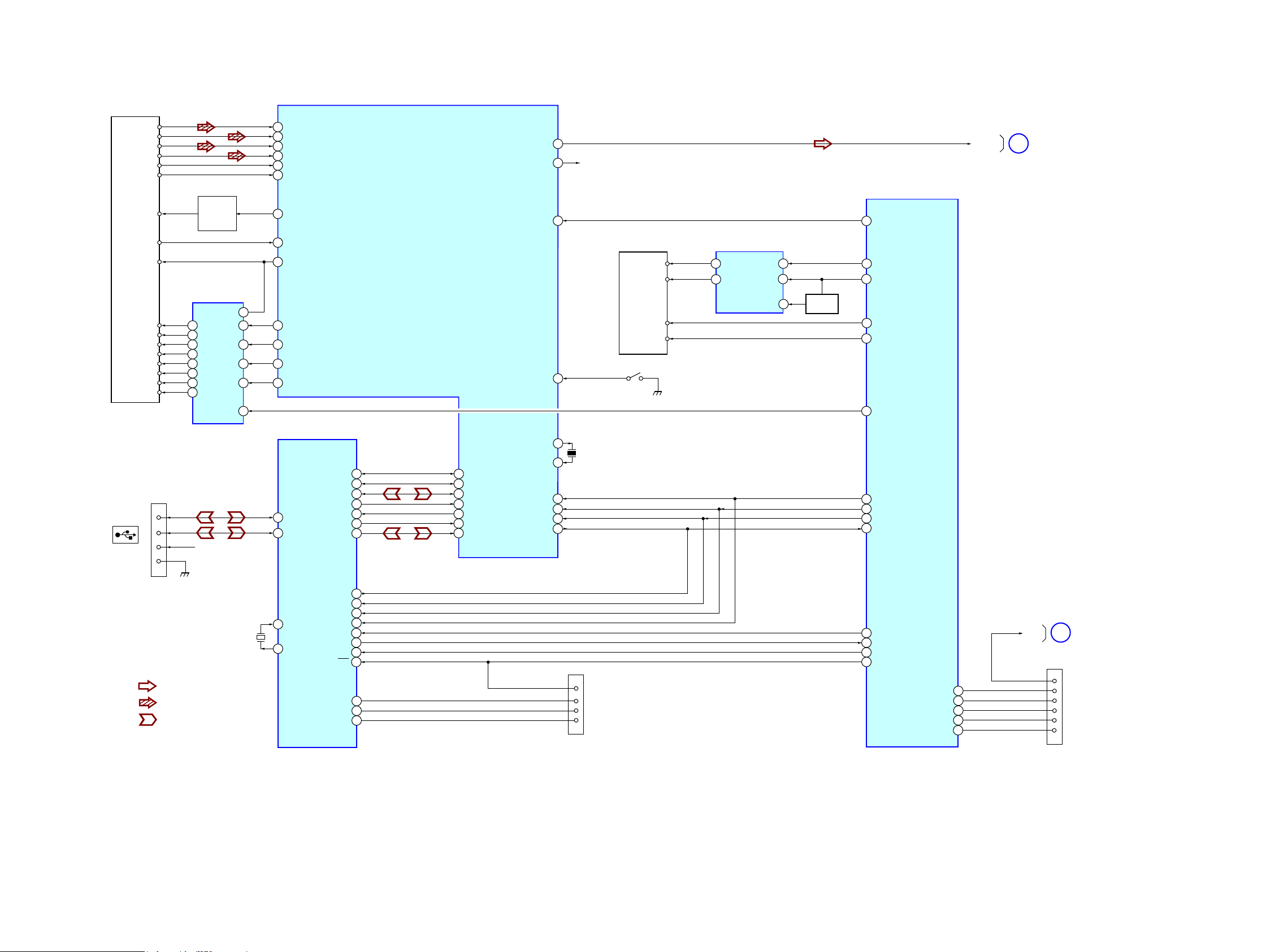
5-1. ',*5$0$(0%/2&2 –6HomRCD/USB –
OPTICAL PICK-UP BLOCK
(DA11MMVGP)
5AIN
7
6CIN
8DIN
13
14
18 LDD
19
11 VREF
25 SPDO
24 SLDO
23 TDO
22 FDO
VREF
SP+
SL+
A
B
C
D
E
F
LD
MD
FOCUS/TRACKING COIL DRIVE,
SPINDLE/SLED MOTOR DRIVE
SP-
SL-
T+
T-
F+
F-
1
12
17
27
AUTOMATIC
POWER
CONTROL
Q201
IC301
VO1+2
VO1VO2+11
VO2VO3+18
VO3VO4+26
VO4-
MUTE
BIAS
IN2’
IN3’
IN4’
23
3
IN1
9
20
24
7
BIN
EIN
FIN
LDS
CD-MP3 PROCESSOR
IC101
LCHO
RCHO R-ch78
RESB
LIMIT-SW
HCD-GPX3G
76
47
CD MECHANISM DECK
(CDM76B-D1BD76)
M+
M-
OPEN SW
CLOSE SW
32
S001
(LIMIT)
LOADING MOTOR DRIVE
IC505
OUT2
2
OUT1
4
RIN
FIN
VREF
9
7
MOTOR
CONTROL
1
Q518
41
CD-RST
CD-M+
23
CD-M-
25
MTR-OPEN
27
MTR-CLOSE
28
CD-M-MUTE
40
SYSTEM CONTROL
IC501 (1/3)
CD/USB-L
A
MAIN
Section
(Page 20)
CN1000
3
D+
2
D-
(USB)
1
4
5FKLVRPLWWHGGXHWRVDPHDV/FK
6LJQDOSDWK
: AUDIO
: CD
: USB
VBUS+5V
X901
12MHz
38 UHD+
37 UHD-
CF1
6
CF2
7
USB CONTROL
IC901
LRCK 28
BCLK
SDAT
P20
P70
P24
P22
SI0 10
SO0
SCK0
P16 15
URX1
UTX1
P71
RES 2
DBGP0
DBGP1
DBGP2 25
XOUT
72
X101
73
43CE
44CL
45DI
46DO
DBGP0
DBGP1
DBGP2
16.934MHz
9
CN901
8
FLASH
( )
PROGRAMMING
7
5
42
CD-CE
CD-CLK
37
CD-DO
35
36
CD-DI
USB-TXD24
USB-RXD
22
USB-SLEEP
38
43
USB-RST
SFT-DEBUG 1
SFT-DEBUG 4
SFT-DEBUG 3
SFT-DEBUG 2 32
CNVSS 9
RESET
31
34
33
DISPLAY/POWER
B
8
2
3
5
6
7
Section
(Page 21)
CN500
(PROGRAMMING)
PCMLRSY
62
PCMBCK
27
26
32
46
33
31
9
11
44
45
47
23
24
63
64
65
33
34
35
PCMDATA
PCMREQ
STREQ
STCK
STDATA
XIN
TRESET
HCD-GPX3G
1919
HCD-GPX3G
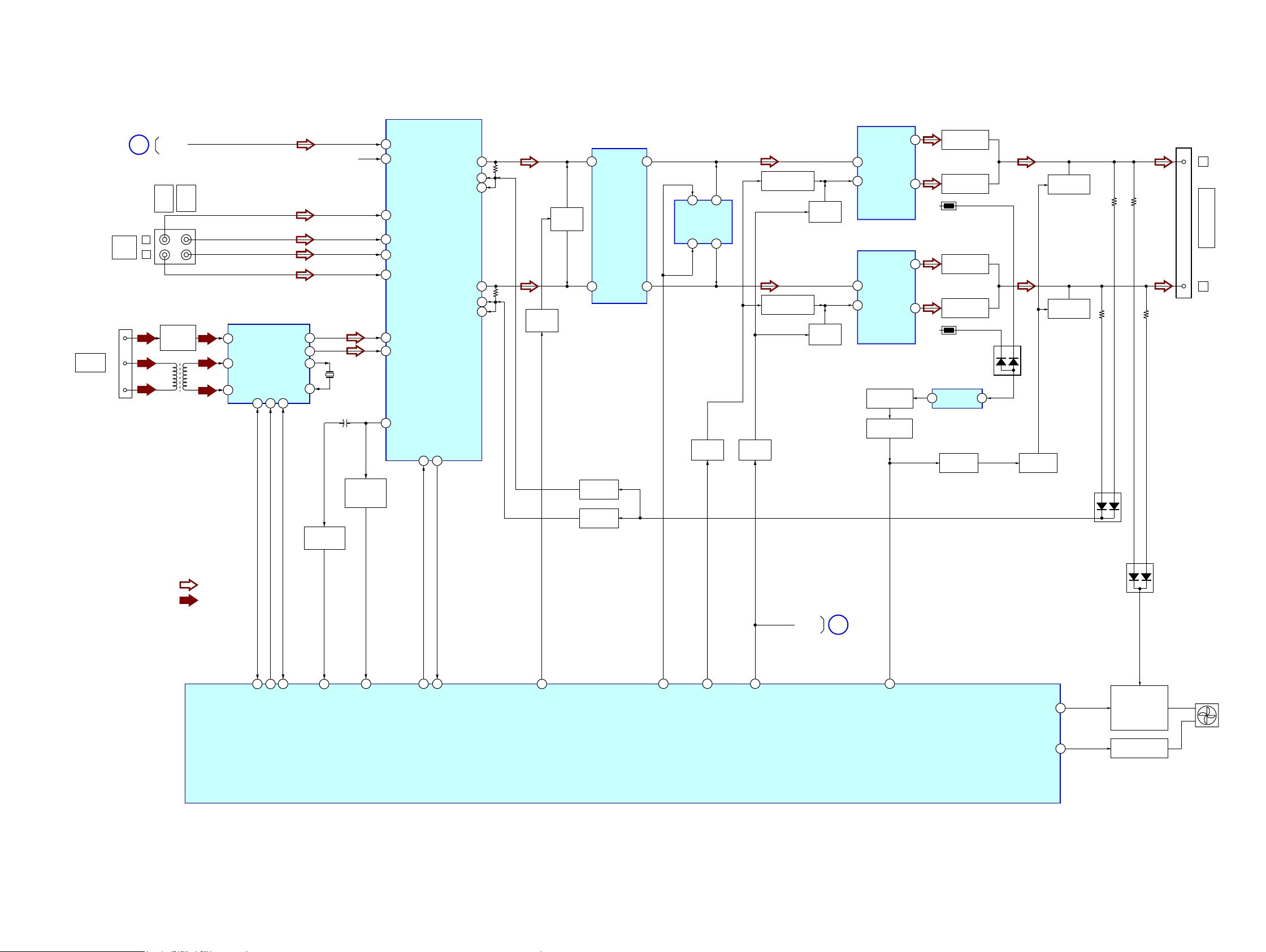
5-2. ',$*5$0$(0BLOC2 –6HomRMAIN –
(Page 19)
ANTENNA
FM/AM
CD/USB
Section
FM
AM
AM
AUDIO
IN
CN103
3
2
1
14
CD/USB-L
A
TV/
PC/
DVD/
GAME
SAT
J801
L
R
FL101
BAND-PASS
FILTER
L101
6LJQDOSDWK
: AUDIO
: FM/AM
AM/FM-DET,OSC,MIX,PLL,IF AMP
FRF1
4
ARF2
7
ARF1
6
LOUT
ROUT
IIC/RDSI
8CK10DA13
X1
X2
IC101
15
14
18
19
Q525,D520
VAC S
CONTROL
R-ch
X101
32.768kHz
+
POWER
ILLUMINATOR
CONTROL
Q803,D801
29
1
30
28
2
40
31
39
4
CDMP3-L
CDMP3-R
TV-L
DVD-L
DVD-R
TV-R
ST-L
ST-R
SAOUT
INPUT SELECTOR
IC800
CLOCK
DATA
15 16
OUT 1
BB11
BB21
OUT 2
BB22
BB12
INA-
MUTE
SWITCH
Q805
2
INB+
5
DBFB CTL
Q804
DBFB CTL
Q806
PREAMP
17
18
19
14
13
12
MUTE
DRIVE
Q517
IC1404
AOUT
BOUT
1
CEC DATA SWITCH
Q1411
75
INB+
BOUT
CLOCK
IC1411
AOUT
INA+
13
7
CEC DATA SWITCH
Q1410
SWITCH
DRIVER
Q1479
SWITCH
DRIVER
Q1407
RESET
SWITCH
Q1416
RESET
SWITCH
Q1417
3
IN
CSD
5
3
IN
CSD
5
HO
POWER AMP
IC1408
LO
HO
POWER AMP
IC1409
LO
OTP DRIVE
Q1469, 1470
SD-SLOW DRIVE
Q1474
11
14
11
BOOSTER
BOOSTER
TH1402
BOOSTER
BOOSTER
TH1403
COMPARATOR
IC1405
OUT
1
PROTECTION
Q1449
Q1420
Q1421
Q1424
Q1425
IN
D1417
2
PROTECTION
Q1448
PROTECTION
Q1445,1456
PROTECTION
Q1446,1457
D1403
D1435
TB4001
3
2
L
FRONT SPEAKERS
,03('$1&(86(ȍ
R
DISPLAY/
AMP-RST
C
POWER
Section
(Page 21)
HCD-GPX3G
47
ST-DATA
48
50
ST-CLK
ST-RDS
66
VACS
65
ILLUM
51
52
AUDIO-CLK
AUDIO-DATA
45
FRT-MUTE
SYSTEM CONTROL
IC501 (2/3)
2020
26
AMP-CLK
56
AMP-OCP
58
AMP-RST
55
/SD-SLOW
FAN-DRIVE
FAN-LOCK
FAN MOTOR DRIVE
57
53
Q1439, Q1441,
Q1451, Q1453,
Q1458
FAN MOTOR LOCK
Q1447
DC FAN
 Loading...