

Sony DVS-7300, DVS-7350 System System User Manual

Operation Software
BZS-7020
User’s Guide
Digital Video Switcher System
DVS-7300/7350 System
2nd Edition
Software Version 3.30 and Later
[English]

NOTICE TO USERS
© 1995 Sony Corporation. All rights reserved. This manual
or the software described herein, in whole or in part, may
not be reproduced, translated or reduced to any machine
readable form without prior written approval from Sony
Corporation.
SONY CORPORATION PROVIDES NO WARRANTY WITH
REGARD TO THIS MANUAL, THE SOFTWARE OR
OTHER INFORMATION CONTAINED HEREIN AND
HEREBY EXPRESSLY DISCLAIMS ANY IMPLIED
WARRANTIES OF MERCHANTABILITY OR FITNESS FOR
ANY PARTICULAR PURPOSE WITH REGARD TO THIS
MANUAL, THE SOFTWARE OR SUCH OTHER
INFORMATION. IN NO EVENT SHALL SONY
CORPORATION BE LIABLE FOR ANY INCIDENTAL,
CONSEQUENTIAL OR SPECIAL DAMAGES, WHETHER
BASED ON TORT, CONTRACT, OR OTHERWISE,
ARISING OUT OF OR IN CONNECTION WITH THIS
MANUAL, THE SOFTWARE OR OTHER INFORMATION
CONTAINED HEREIN OR THE USE THEREOF.
Sony Corporation reserves the right to make any
modification to this manual or the information contained
herein at any time without notice.
The software described herein may also be governed by
the terms of a separate user license agreement.
Chapter 1 Overview
1-2

Table of Contents
Chapter 1
Overview
Chapter 2
Location and
Function of
Parts
Introduction .............................................................................. 1-2
Features of the DVS-7300/7350 Switcher System.................. 1-4
Overall Organization................................................................ 2-2
Mix/Effects Banks..................................................................... 2-7
Signal Selection Section ..................................................... 2-8
Transition Control Section................................................ 2-11
FlexiPad™ ........................................................................ 2-14
Key Control Section ......................................................... 2-16
Program/Preset Bank............................................................. 2-20
Signal Selection Section ................................................... 2-21
Transition Control Section................................................ 2-22
Downstream Keyer Control Section................................. 2-24
Auxiliary Bus Bank ................................................................ 2-27
Numeric Keypad Section ....................................................... 2-29
Menu Control Section and Floppy Disk Drive..................... 2-31
Key Frame Control Section
(BKDS-7030 Key Frame Control Panel
Unit – Option) ................................................................. 2-33
DME Control Section
(BKDS-7031 DME Control Panel Unit – Option) ....... 2-36
SHOT BOX Control Section
(BKDS-7033 Memory Recall Control Panel
Unit – Option) ................................................................. 2-38
Chapter 3
Basic Menu
Operations
Menu Organization .................................................................. 3-2
Basic Menu Operations............................................................ 3-6
Table of Contents
i

Table of Contents
Chapter 4
Basic
Operations for
Image Creation
(Continued)
Before Beginning Image Creation........................................... 4-3
Video Signal Flow .............................................................. 4-3
Signal Selection .................................................................. 4-6
Using the Mix/Effects Banks.................................................. 4-10
Backgrounds and Keys ..................................................... 4-10
Basic Operating Procedure ............................................... 4-11
Selecting the Next Transition ........................................... 4-14
Selecting the Transition Type........................................... 4-17
Setting a Transition Limit................................................. 4-19
Super Mix Settings ........................................................... 4-20
Using the Program/Preset Bank............................................ 4-21
Overview .......................................................................... 4-21
Basic Operating Procedure ............................................... 4-21
Basic Downstream Key Operations ...................................... 4-24
Overview .......................................................................... 4-24
Basic Operating Procedure ............................................... 4-28
Executing a Transition ........................................................... 4-31
Overview .......................................................................... 4-31
Setting the Transition Rate ............................................... 4-32
Executing a Transition...................................................... 4-34
Keys.......................................................................................... 4-39
Overview .......................................................................... 4-39
Basic Operation for Key Settings Using a Menu ............. 4-46
Basic Operation for Key Settings Using the Key Control
Section................................................................... 4-64
Downstream Keys............................................................. 4-68
Wipes ....................................................................................... 4-92
Overview .......................................................................... 4-92
Basic Operation for Wipe Settings ................................... 4-98
PGM/PST Wipes and Downstream Keyer Wipes .......... 4-112
DME Wipes ........................................................................... 4-120
Overview ........................................................................ 4-120
Basic Operation for DME Wipes.................................... 4-125
DME Wipe Settings........................................................ 4-127
Notes on Building a Key Frame Effect With User
Programmable DME ........................................... 4-134
Table of Contents
ii

Chapter 4
Basic
Operations for
Image Creation
(Continued)
Color Backgrounds............................................................... 4-137
Overview ........................................................................ 4-137
Color Background Setting Operations............................ 4-138
Status Display........................................................................ 4-140
Basic Status Display Operation ...................................... 4-140
Chapter 5
Chroma Keying
Chapter 6
Frame Memory
Operations
Overview.................................................................................... 5-2
Basic Chroma Key Operations................................................ 5-3
Preparations ........................................................................ 5-3
CHROMA KEY Menu ....................................................... 5-4
Basic Operations................................................................. 5-5
Adjusting the Chroma Key Image ...................................... 5-7
Video Signal Adjustment.................................................. 5-12
Chroma Key Masking....................................................... 5-13
Upgrade Board Mode Selection ............................................ 5-15
Dual Mode Chroma Keying................................................... 5-16
Dual Mode CHROMA KEY Menu .................................. 5-16
Enhanced Chroma Keying (Single Mode)............................ 5-17
Overview .......................................................................... 5-17
Single Mode CHROMA KEY Menu................................ 5-18
Clean Chroma Key ........................................................... 5-19
Additive Mix..................................................................... 5-22
Image Adjustment Functions............................................ 5-23
Video Signal Adjustment and Spot Color Adjustment..... 5-31
Dual Masking ................................................................... 5-34
Overview.................................................................................... 6-2
Frame Memory Functions .................................................. 6-2
Basic Frame Memory Operations ........................................... 6-5
Preparations ........................................................................ 6-5
FRAME MEMORY Menus................................................ 6-6
Selecting the Input Video ................................................... 6-7
Writing a Frame to Memory – MANUAL ......................... 6-7
Writing a Frame With a Trail to Memory – PAINT......... 6-12
Moving the Frame – MOVE............................................. 6-14
Linking Frame Memories – LINK.................................... 6-15
Write-Protect Setting – LOCK ......................................... 6-16
Table of Contents
iii

Table of Contents
Chapter 7
Snapshots
Chapter 8
Key Frame
Operations
Overview.................................................................................... 7-2
Snapshots and Registers ..................................................... 7-3
Snapshot Operations ................................................................ 7-6
Snapshot Operations Using the Numeric Keypad
Section..................................................................... 7-6
M/E Snapshot Operations Using the FlexiPad ................. 7-10
DME Snapshot Operations ............................................... 7-14
Overview.................................................................................... 8-2
Key Frames and Effects...................................................... 8-2
Control of DME Effects ..................................................... 8-3
Organization of Registers for Key Frame Effects .............. 8-4
Operation Sequence ............................................................ 8-5
Key Frame Creation and Editing............................................ 8-6
Accessing a Register........................................................... 8-6
Specifying Sub-Registers and Edit Points .......................... 8-7
Creation .............................................................................. 8-8
Insertion .............................................................................. 8-9
Modification ..................................................................... 8-10
Deletion ............................................................................ 8-12
Movement......................................................................... 8-13
Copying ............................................................................ 8-14
Undoing the Effect of an Edit........................................... 8-14
Time Settings........................................................................... 8-15
Key Frame Duration and Effect Duration ........................ 8-15
Changes in Effect Duration Due to Inserted
Key Frames ........................................................... 8-17
Changes in Effect Duration Due to Key Frame
Deletion ................................................................. 8-18
Delay Setting .................................................................... 8-19
Path Settings............................................................................ 8-20
Displaying the PATH Menu ............................................. 8-20
Basic Path Setting Operations .......................................... 8-21
Executing and Saving Effects ................................................ 8-26
Executing Effects.............................................................. 8-26
Run Mode Settings ........................................................... 8-28
Saving Effects................................................................... 8-30
Displaying Effect Information............................................... 8-31
Table of Contents
iv

Chapter 9
Registers
Overview.................................................................................... 9-2
Functions Relating to Registers .......................................... 9-3
Basic Register Operations........................................................ 9-5
Manipulating Snapshot and Key Frame Effect Registers... 9-6
Setting Snapshot Attributes .............................................. 9-13
Selecting the Sub-Registers in the “USER” Group .......... 9-15
Channel-to-Channel Copying of DME Registers............. 9-16
Chapter 10
Floppy Disk
Operations
Chapter 11
Copy and
Swap
Operations
Chapter 12
MISC Menu
Operations
Chapter 13
Setup
Overview.................................................................................. 10-2
Disks and Data Held ......................................................... 10-2
Disk Functions.................................................................. 10-3
Disk Operations ...................................................................... 10-4
Overview.................................................................................. 11-2
Basic Copy and Swap Operations ......................................... 11-5
Copy and Swap Using Menu Operations ......................... 11-5
Copying Using Button Operations ................................... 11-7
Overview.................................................................................. 12-2
Port Enable Settings ............................................................... 12-3
Controlling the Positioner Function With a Tablet............. 12-5
Safe Title Settings ................................................................... 12-8
Video Input Adjustment (Video Process Function) .......... 12-10
Overview.................................................................................. 13-2
Saving and Recalling Setup Data ..................................... 13-2
Displaying the SETUP Menu ........................................... 13-3
Setup Relating to the Overall Switcher System (SYSTEM
Menu)............................................................................... 13-4
Setup Relating to Input/Output Signals
(INPUT/OUTPUT Menu) ............................................ 13-13
Setup Relating to Keyers, Wipes and Other Effects
(EFFECT Menu)........................................................... 13-41
Setup Relating to Interfaces With Peripheral Devices
(PERIPH Menu) ........................................................... 13-47
Setup Relating to Operations From the Control Panel
(OPERATION Menu) .................................................. 13-66
Table of Contents
v

Table of Contents
Chapter 14
DIAGNOSIS
Menu
Operations
Appendixes
Overview.................................................................................. 14-2
Operations ............................................................................... 14-3
Analog Output Board Adjustments .................................. 14-3
Analog Input Board Adjustments ..................................... 14-6
Checking the Board Configuration................................... 14-7
Displaying Error Messages............................................... 14-8
Wipe Patterns........................................................................... A-2
Standard Wipes.................................................................. A-2
Enhanced Wipes ................................................................ A-3
Mosaic Wipes (including diamond dust wipe) .................. A-3
DME Wipe Patterns ................................................................ A-4
Menu System ............................................................................ A-7
M/E-1, M/E-2, and M/E-3 KEY 1 Menus,
and M/E-1, M/E-2, and M/E-3 KEY 2 Menus ....... A-7
DSK Menu......................................................................... A-9
M/E-1, M/E-2, and M/E-3 DME WIPE Menus............... A-11
PGM/PST WIPE Menu ................................................... A-13
DSK WIPE Menu ............................................................ A-14
M/E-1, M/E-2, and M/E-3 DME WIPE Menus,
and P/P DSK DME WIPE Menu.......................... A-15
M/E-1, M/E-2, and M/E-3 BKGD/TRANS Menus......... A-16
STATUS Menu................................................................ A-17
FRAME MEMORY 1, FRAME MEMORY 2 Menus.... A-21
KEY FRAME Menu ........................................................ A-22
M/E-1, M/E-2, and M/E-3 CHROMA KEY Menus ....... A-18
REGISTER Menu............................................................ A-21
DISK Menu...................................................................... A-23
MISC Menu ..................................................................... A-24
SETUP Menu................................................................... A-25
DIAGNOSIS Menu ......................................................... A-30
Table of Contents
vi
Index ...........................................................................................I-1

Chapter 1
Overview
1 Overview

Chapter 1
Overview
Introduction ............................................................................................... 1-2
Features of the DVS-7300/7350 Switcher System................................... 1-4

Introduction
This is the User's Guide for the BZS-7020 Operation Software for a DVS7300/7350 switcher system. It mainly describes the operation of a DVS-7300
switcher system using the BKDS-7011/7012 control panel or a DVS-7350
switcher system using the BKDS-7021/7022/7023 control panel.
DVS-7300/7350 is a system name. It does not refer to any specific hardware
device.
For details of the DVS-7300/7350 system, see the following section, “Terms
for system types”.
System configurations and terminology
This manual refers to the principal components of the DVS-7300/7350
switcher system by the terms listed below.
Terms for system components
The following table lists the full model names of system components and the
terms used to identify them in this manual.
Full model name
DVS-7000 Digital Video Switcher Switcher
BKDS-7021/7022/7023 TYPE-4D
Switcher Control Panel
BKDS-7011/7012 TYPE-3D Switcher
Control Panel
BZS-7020 Operation Software Software
DMK-7000 Digital Multi Keyer Downstream keyer
BKDS-7032 DSK Control Panel Unit Downstream keyer control section
DME-7000 or other Digital Multi Effects
unit
a) Unless it is necessary to distinguish “3.5-M/E panel” and “3-M/E panel” the term “control
panel” is used.
b) In a 3.5-M/E panel, the downstream keyer control section is built-in as standard.
Term used in this manual
3.5-M/E panel
3-M/E panel
DME unit
a)
a)
b)
1-2
Chapter 1 Overview

Terms for system types
This manual also uses the terms listed below to distinguish different types of
system where necessary.
System characteristics Term used
• Switcher system using a 3.5-M/E panel (BKDS-7021/7022/7023)
as the switcher control panel
• Switcher system with a DMK-7000 Digital Multi Keyer connected
Switcher system using a 3-M/E panel (BKDS-7011/7012) as the
switcher control panel
System equipped with an option board and with system settings to
support composite signal format
System equipped with an option board and with system settings to
support component signal format
a) In the case of a system equipped with a DMK-7000 and BKDS-7032 DSK Control Panel Unit,
where required the term “3-M/E system equipped with a downstream keyer” is also used.
About the BZS-7020 Operation Software
The BZS-7020 Operation Software is a program for operating the DVS-7300/
7350 system hardware from the control panel.
The BZS-7020 software is supplied on three floppy disks, one each for the
switcher, the control panel, and the downstream keyer. The software is
installed from the floppy disk drive on the control panel, and copied to nonvolatile memory (flash memory) in each of the units.
For details of the software installation procedure, see page 13-6 in this
manual, and also refer to the DVS-7000 Installation Manual.
DVS-7350 system
or 3.5-M/E system
DVS-7300 system
or 3-M/E system
D2 system
D1 system
a)
Related manuals
The following manuals are supplied with the DVS-7000 Digital Video
Switcher:
• DVS-7000 Operation Manual
• DVS-7000 Installation Manual
• DVS-7000 Maintenance Manual Part 1
The following manuals are supplied with the DMK-7000 Digital Multi
Keyer:
• DMK-7000 Operation Manual
• DMK-7000 Installation Manual
• DMK-7000 Maintenance Manual Part 1
Chapter 1 Overview
1-3

Features of the DVS-7300/7350 Switcher
System
The DVS-7300/7350 switcher system offers high performance and high
functionality in a system based on the DVS-7000 Digital Video Switcher.
The following are some of the features of this system.
Full-featured video effects
M/E banks
There are three M/E banks, each with equivalent functionality. Each bank
includes two keyers which can be operated independently and
simultaneously.
The output from any M/E bank can be input as a background signal to any
other, for further keying and other operations.
PGM/PST bank (operation coupled to a DMK-7000)
In a DVS-7350 system, the three M/E banks are supplemented by a PGM/
PST bank, for manipulating the final program output from the switcher.
Using the PGM/PST bank, you can insert a total of four downstream keys
into the final background output. These operations are controlled from the
switcher control panel, but the processing is carried out by a DMK-7000
Digital Multi Keyer connected to the system.
In a DVS-7300 system, by connecting a DMK-7000, and equipping the
control panel with a BKDS-7032 DSK Control Panel Unit, you can again
control the insertion of a maximum of four downstream keys.
DME wipes (operation coupled to a DME)
By connecting a DME-7000 or other Digital Multi Effects unit, you can use
the control panel to carry out DME wipes, using DME effects (the “DME
LINK™” function).
System configuration flexibility
Wide range of options
In addition to the two basic control panel types, that is, 3.5-M/E and 3-M/E
panels, there is a wide range of options, allowing just the features required to
be installed in a system.
Support for D1 and D2 formats
Except for some options, both D1 (component) and D2 (composite) signal
formats are supported. A simple control panel operation switches between
the D1 and D2 selections, and also in the case of D1 format between 525- and
625-line systems.
1-4
Chapter 1 Overview

Convenient interfaces with external equipment
Using the DVS-7000 along with the DVS-V6464B Sony Routing Switcher,
you can make up a large-scale switcher system.
Connecting the BVE-9100 Editing Control Unit to your system will allow
you to carry out such advanced editing operations as ISR (System Status
Reporting) and EDL (Edit Decision List ) management.
Powerful remote control functions
You can connect the BKDS-2010 Control Panel to the DVS-7000 and use it
as a separate panel exclusively for the M/E banks.
For key adjustment operations such as chroma key adjustment, the BKDS7060 Keyer Remote Control Panel is available.You can use the dedicated
panel connected to the DVS-7000 to remote-control the auxiliary bus and
Shot Box operations.
Operation adapted to live operation
The DVS-7300/7350 is not only a fully featured switcher system for postproduction tasks, but also well adapted to live broadcast applications, since
the control panel has been designed to provide the necessary rapid
operability.
Combined use of menu settings and button operation
All detailed settings for video processing are carried out in menus, but for
some more frequently used operations you can carry out the selections and
adjustments by direct button operations on the control panel. In particular,
clip, gain, density and other basic parameter settings can be controlled using
the three knobs provided on each M/E bank, quite independently of the
currently accessed menu.
Snapshot function
The DVS-7300/7350 system has a comprehensive snapshot function, which
allows a collection of settings for a particular effect to be saved in memory,
and recalled as required for an instant return to the settings. Snapshots can be
saved from memory to floppy disk, and reloaded into the system when
required.
Snapshots can reflect the overall system settings, or can apply only to key,
wipe, or DME wipe settings for a particular M/E bank. These latter can be
easily saved and recalled using the buttons of the FlexiPad™ provided on the
M/E bank.
Chapter 1 Overview
1-5

Chapter 2
Location and Function of Parts
2 Location and Function of
Parts

Chapter 2
Location and Function of Parts
Overall Organization................................................................................. 2-2
Mix/Effects Banks...................................................................................... 2-7
Signal Selection Section ......................................................................2-8
Transition Control Section................................................................. 2-11
FlexiPad™ .........................................................................................2-14
Key Control Section .......................................................................... 2-16
Program/Preset Bank .............................................................................. 2-20
Signal Selection Section ....................................................................2-21
Transition Control Section................................................................. 2-22
Downstream Keyer Control Section.................................................. 2-24
Auxiliary Bus Bank ................................................................................. 2-27
Numeric Keypad Section ........................................................................ 2-29
Menu Control Section and Floppy Disk Drive...................................... 2-31
Key Frame Control Section
(BKDS-7030 Key Frame Control Panel Unit – Option)............... 2-33
DME Control Section
(BKDS-7031 DME Control Panel Unit – Option) ........................ 2-36
SHOT BOX Control Section
(BKDS-7033 Memory Recall Control Panel Unit – Option)........ 2-38
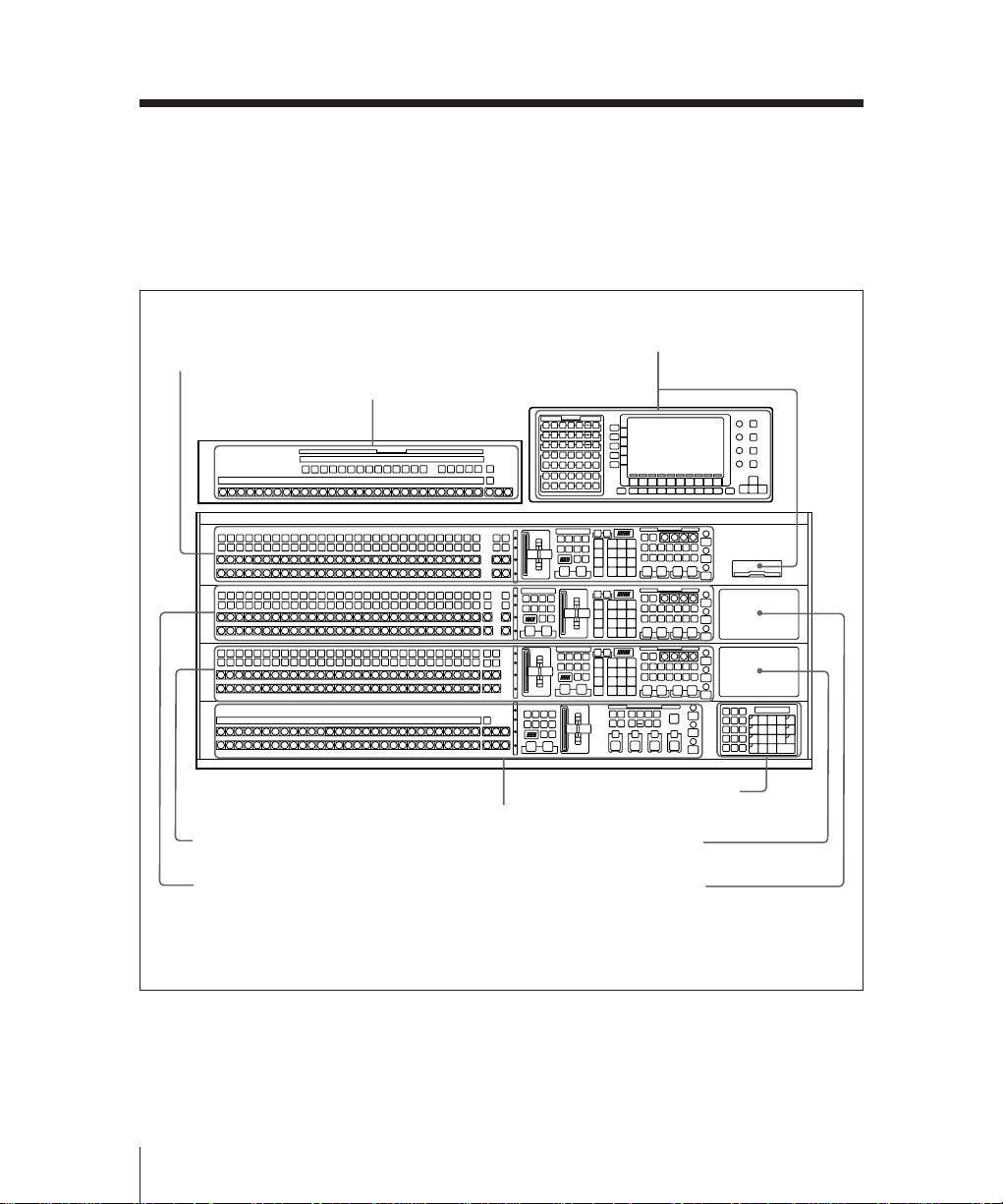
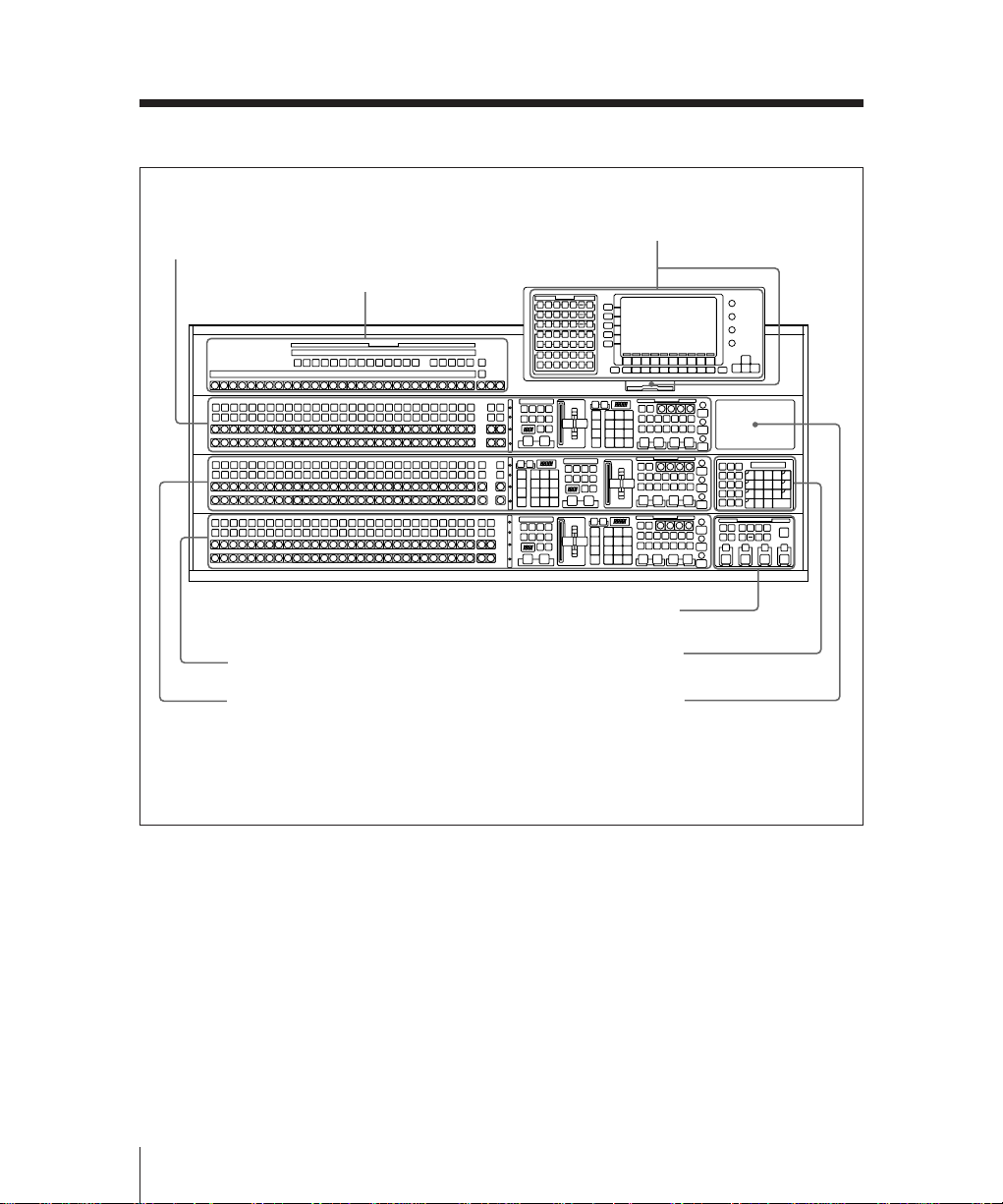
Overall Organization
Overall Organization
The control panel is divided into several
blocks of buttons and other controls, as
shown in the illustrations on this and the
following pages. See the page numbers
indicated in parenthesis for more details.
M/E-1 bank (page 2-7)
Auxiliary bus bank (page 2-27)
AUX
M/E-1
K1
K2
A
B
M/E-2
K1
K2
A
B
M/E-3
K1
K2
A
B
Menu control section and
floppy disk drive (page 2-31)
2-2
BLACK
PGM
BLACK
PST
Numeric keypad sectiona) /
option fitting panel 3 (page 2-29)
Option fitting panel 2
Option fitting panel 1
M/E-3 bank (page 2-7)
M/E-2 bank (page 2-7)
PGM/PST bank
(page 2-20)
a)It is possible to fit the numeric keypad section in any of the three option fitting panels.
BKDS-7021 Type 4D control panel (3.5-M/E panel)
Chapter 2 Location and Function of Parts
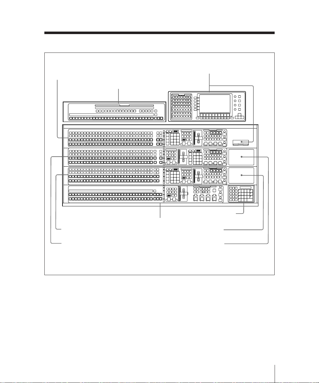
M/E-1 bank (page 2-7)
Auxiliary bus bank (page 2-27)
AUX
M/E-1
K1
K2
A
B
M/E-2
K1
K2
A
B
M/E-3
K1
K2
A
B
PGM
PST
M/E-3 bank (page 2-7)
PGM/PST bank
(page 2-20)
Menu control section and
floppy disk drive (page 2-31)
Numeric keypad sectiona) /
option fitting panel 3 (page 2-29)
Option fitting panel 2
M/E-2 bank (page 2-7)
Option fitting panel 1
a)It is possible to fit the numeric keypad section in any of the three option fitting panels.
BKDS-7022 Type 4D control panel (3.5-M/E panel)
Chapter 2 Location and Function of Parts
2-3
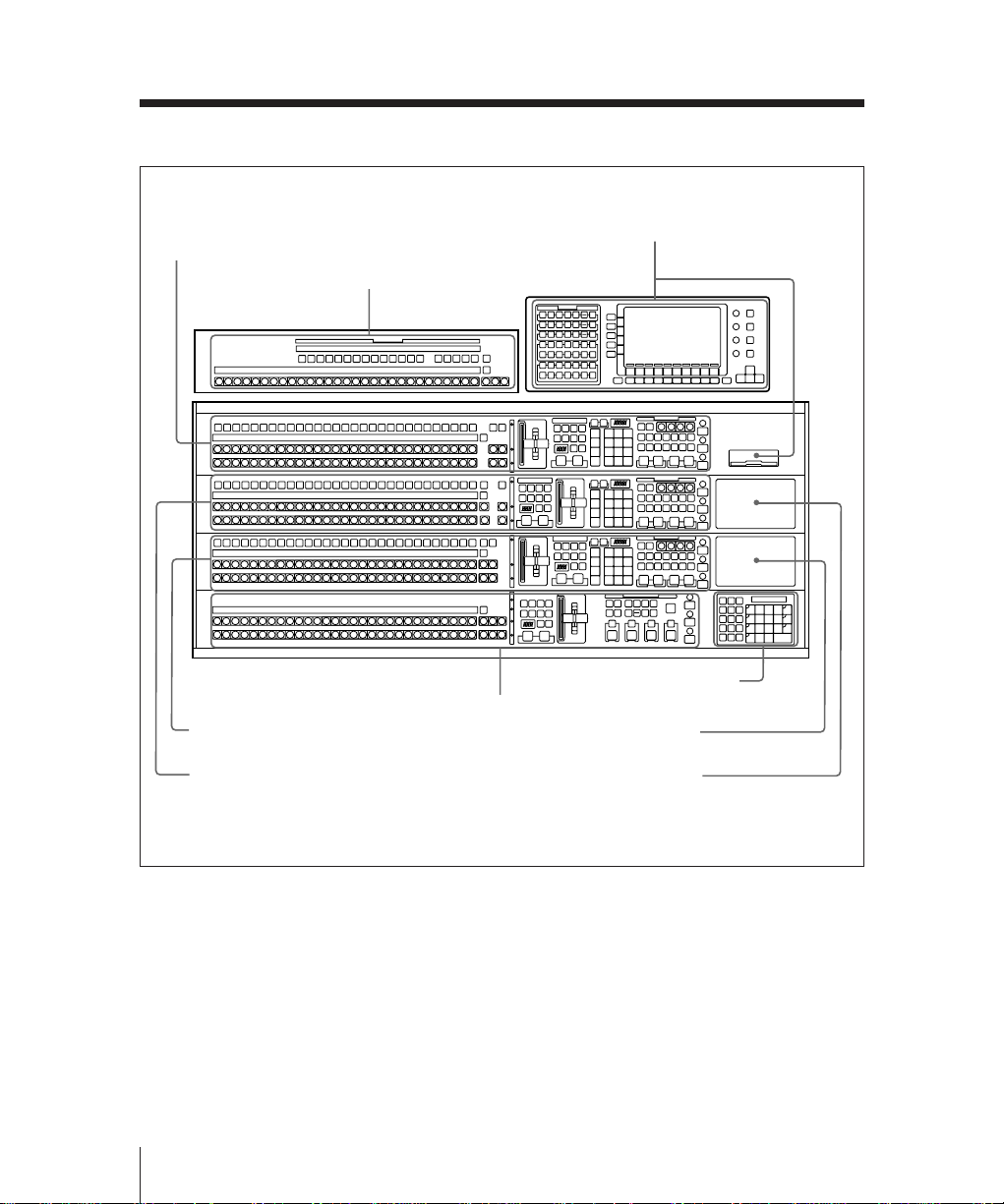
Overall Organization
M/E-1 bank (page 2-7)
Auxiliary bus bank (page 2-27)
AUX
M/E-1
K1
K2
A
B
M/E-2
K1
K2
A
B
M/E-3
K1
K2
A
B
PGM
PST
Menu control section and
floppy disk drive (page 2-31)
2-4
Numeric keypad sectiona) /
option fitting panel 3 (page 2-29)
Option fitting panel 2
Option fitting panel 1
M/E-3 bank (page 2-7)
M/E-2 bank (page 2-7)
PGM/PST bank
(page 2-20)
a)It is possible to fit the numeric keypad section in any of the three option fitting panels.
BKDS-7023 Type 4D control panel (3.5-M/E panel)
Chapter 2 Location and Function of Parts
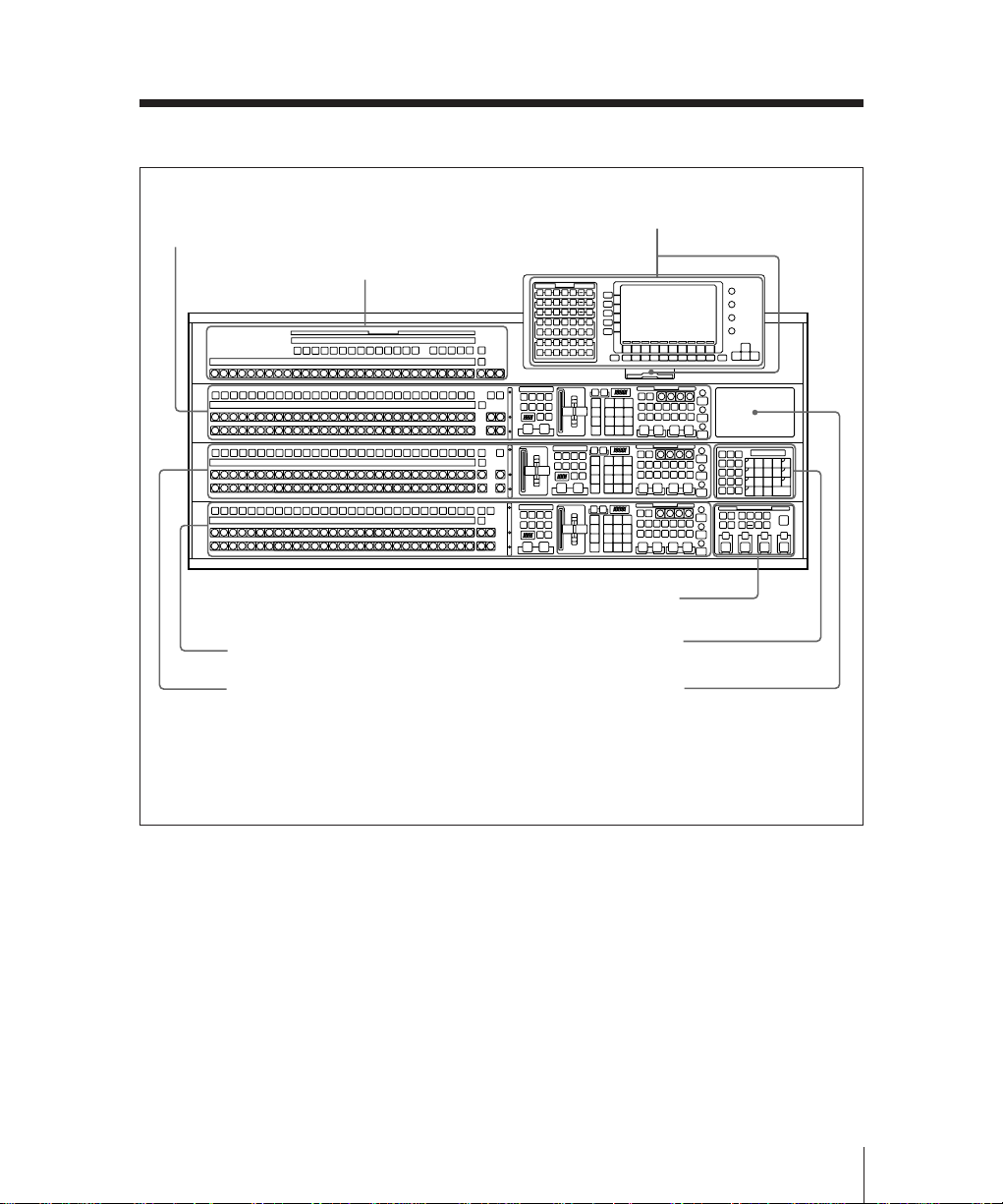
Menu control section and
floppy disk drive (page 2-31)
M/E-1 bank (page 2-7)
Auxiliary bus bank (page 2-27)
AUX
M/E-1
K
A
B
M/E-2
K
A
B
M/E-3
K
A
B
Downstream keyer control section /
option fitting panel 3a) (page 2-24)
M/E-3 bank (page 2-7)
M/E-2 bank (page 2-7)
Numeric keypad section / option
fitting panel 2b) (page 2-29)
Option fitting panel 1
a)It is possible to fit the optional downstream keyer control section in any of the three option
fitting panels.
b)It is possible to fit the numeric keypad section in any of the three option fitting panels.
BKDS-7011 Type 3D control panel (3-M/E panel)
Chapter 2 Location and Function of Parts
2-5
Overall Organization
M/E-1 bank (page 2-7)
Auxiliary bus bank (page 2-27)
AUX
M/E-1
K
A
B
M/E-2
K
A
B
M/E-3
K
A
B
M/E-3 bank (page 2-7)
M/E-2 bank (page 2-7)
Menu control section and
floppy disk drive (page 2-31)
Downstream keyer control section /
option fitting panel 3a) (page 2-24)
Numeric keypad section / option
fitting panel 2b) (page 2-29)
Option fitting panel 1
2-6
a)It is possible to fit the optional downstream keyer control section in any of the three option
fitting panels.
b)It is possible to fit the numeric keypad section in any of the three option fitting panels.
BKDS-7012 Type 3D control panel (3-M/E panel)
Chapter 2 Location and Function of Parts
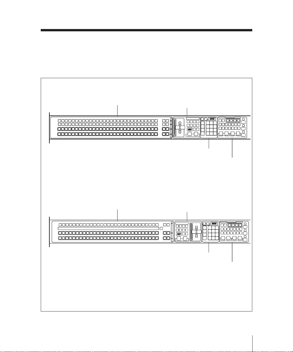
Mix/Effects Banks
The three mix/effects banks (M/E-1, M/E2, and M/E-3) provide separate mix/effects
functionality.
BKDS-7012/7021/7022
M/E-1
K1
K2
A
BLACK
BLACK
B
BKDS-7011/7023
a)
Signal selection section
(page 2-8)
a)
Signal selection section
(page 2-8)
These three banks are functionally and
structurally similar; the following
illustration shows the M/E-1 bank by way
of example.
Transition control section
(page 2-11)
FlexiPad™ (page 2-14)
Key control section
(page 2-16)
Transition control section
(page 2-11)
M/E-1
K
A
B
a)Depending on the control panel model and the
M/E bank, the positions of the transition control
section and the FlexiPad may be reversed.
M/E bank
FlexiPad™ (page 2-14)
Key control section
(page 2-16)
Chapter 2 Location and Function of Parts
2-7
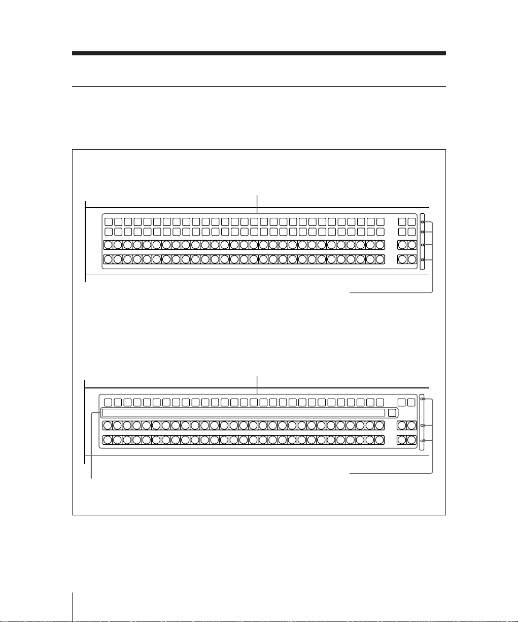
Mix/Effects Banks
Signal Selection Section
This is used for selecting signals on this
M/E bank.
BKDS-7012/7021/7022
1 Cross-point buttons
M/E-1
K1
K2
A
BLACK
BLACK
B
BKDS-7011/7023
M/E-1
K
A
BLACK
BLACK
B
3 Source name display
2 Bus tally indicators
1 Cross-point buttons
2 Bus tally indicators
M/E2M/E
3
M/E2M/E
3
COLOR
BKGD
COLOR
BKGD
COLOR
BKGD
COLOR
BKGD
M/E2M/E
SHIFT
SHIFT
SHIFT
SHIFT
3
M/E2M/E
3
M/E2M/E
1
3
M/E2M/E
M/E2M/E
2
3
3
SHIFT
2-8
Signal selection section
Chapter 2 Location and Function of Parts

1 Cross-point buttons
These buttons select the signals used for
video making on this M/E bank.
Each row of buttons corresponds to one or
more signal buses within the switcher.
Using a setup menu, you can assign any
signals to the first 29 cross-point buttons
in each row. The two buttons at the right
of each row are reentry buttons for
selecting the output signals from the other
mix/effects banks.
The buttons to which you can assign
signals are numbered 0 to 28 from left to
right. By means of a setup operation, you
can assign the rightmost button (number
28) as a shift button. In this case buttons 0
to 27 can be used to select a second set of
signals, numbered 30 to 57, in the shifted
state. To select these shifted signals, hold
down the SHIFT button then press the
required cross-point button.
It is also possible, using a setup menu
operation, to switch the shift button to be
the leftmost button instead of the
rightmost. In this case the assignable
signals are numbered 1 to 28 and 31 to 58.
The setup menu operation assigns signals
to cross-point button columns, so that
naturally buttons select the same signals
regardless of which bank or row they are
in.
K1 (key 1) and K2 (key 2) rows (BKDS7012/7021/7022), K (key) row (BKDS7011/7023):
These buttons select the key signals to
be inserted into the video on this bank.
• On the BKDS-7012/7021/7022, the
K1 row controls the key 1 fill bus,
and the K2 row the key 2 fill bus.
• On the BKDS-7011/7023, the K row
controls both the key 1 and key 2 fill
buses. To delegate these buttons to
the key 1 fill bus press the KEY 1
button in the key control section,
turning it on, and to delegate these
buttons to the key 2 fill bus press the
KEY 2 button in the key control
section, turning it on.
When the K row is delegated to the
key 1 fill bus, a “1” appears below
the key bus tally indicator, and
similarly a “2” when it is delegated
to the key 2 fill bus.
A row (background bus A): These
buttons select the signal for
background A. Except while
executing a background transition, this
bus provides the output of the mix/
effects block.
B row (background bus B): This bus
provides the second background for a
transition, which replaces the
background currently on bus A.
Chapter 2 Location and Function of Parts
2-9

Mix/Effects Banks
Visual indications on cross-point
buttons
The currently selected button in a row (i.e.
the last button pressed) lights amber or
red.
Amber (“low tally”): the signal selected
on the bus does not form part of the
program output from the switcher.
Red (“high tally”): the signal selected on
the bus forms part of the program
output from the switcher.
2 Bus tally indicators
These light when the signal from the
corresponding bus (row of cross-point
buttons) forms part of the output from this
M/E bank.
You can also use these indicators as the
indicators for the video process function.
For more details, see “Changing switcher
functions (OPERATION MODE menu)”
(page 13-73).
3 Source name display (BKDS-7011/
7023 only)
This shows the identifiers of source
signals. When there are two signals
assigned to a cross-point button column,
hold down the SHIFT button at the right
end to show the identifiers assigned to the
shifted buttons.
Again, if the shift button in the cross-point
button row is held down, the second set of
signal names is displayed.
If you are using the switcher and a DVS-B
series routing switcher connected by a
BKDS-7700, the signal names selected on
the routing switcher can be displayed.
2-10
Chapter 2 Location and Function of Parts
Transition Control Section
The buttons in this section control
transitions on the output from this M/E
bank.
1 Key 1 ON/OVER indicator
2 Key 2 ON/OVER indicator
3 Next transition selection buttons
4 Transition type selection buttons
5 Auto transition control section
BKGD
MIX
FRAMES
AUTO
TRANS
NEXT TRANSITION
ON
OVERONOVER
KEY1KEY KEY
2
SUPER
NAM
MIX
DME
1
TRANSITION TYPE
CUT
PRIOR
WIPE
DME
2
a) Sections A and B are
interchanged on alternate M/E
banks.
Transition control section
1 Key 1 ON/OVER indicator
ON: Lights when key 1 is inserted in the
output from this mix/effects bank.
OVER: Lights when key 1 is over key 2.
Section A
a)
Section B
6 Transition indicator
7 Fader lever
2 Key 2 ON/OVER indicator
ON: Lights when key 2 is inserted in the
output from this mix/effects bank.
OVER: Lights when key 2 is over key 1.
Chapter 2 Location and Function of Parts
a)
2-11

Mix/Effects Banks
3 Next transition selection buttons
These buttons determine what the next
transition will apply to.
BKGD: Next transition is a background
transition.
KEY 1: Next transition will insert or
remove key 1. If key 1 is currently
inserted it will be removed, and vice
versa.
KEY 2: Next transition will insert or
remove key 2. If key 2 is currently
inserted it will be removed, and vice
versa.
KEY PRIOR (priority): Next transition
will interchange the priority
relationship between key 1 and key 2.
More than one of these four buttons can be
lit simultaneously.
4 Transition type selection buttons
Press one of these buttons, turning it on, to
determine the type of the next transition.
MIX: In a background transition, the new
video (bus B) fades in as the old video
(bus A) fades out. The new video
level is increased from 0% to 100% as
the old video is reduced from 100% to
0%, in such a way that the overall
signal level is always 100%.
In a key transition, the key fades in
(for insertion) or out (for removal).
NAM (non-additive mix): The old
background and new background
video signals are compared, and the
higher one is used as the output.
The old video is reduced from 100%
to 0% over the second half of the
transition, and the new video level is
increased from 0% to 100% over the
first half, all the while combining the
two signals by non-additive mixing.
SUPER MIX: The old video is reduced
from 100% to 0% over the second half
of the transition, and the new video
level is increased from 0% to 100%
over the first half, all the while
combining the two signals by
(ordinary) mixing.
It is also possible to set the video
levels at the mid-point of the transition
to any value between 0 and 100%, by
using the BKGD/TRANS menu for
the M/E bank.
WIPE: The transition executed will be a
wipe, using the settings in the wipe
setting menu for the M/E bank.
DME 1: The transition will be a wipe-like
effect, using the effects provided by
DME channel 1. This requires at least
one DME-7000 or other Digital Multi
Effects unit to be connected to the
switcher system.
To carry out a dual DME wipe using
the effects provided by two DME
channels, press this button and the
DME 2 button simultaneously, turning
them on.
You can use a setup operation to make
this button select DME 3 or DME 5
instead.
DME 2: The transition will be a wipe-like
effect, using the effects provided by
DME channel 2. This requires at least
two DME-7000 or other DME units to
be connected to the switcher system.
To carry out a dual DME wipe using
the effects provided by two DME
channels, press this button and the
DME 1 button simultaneously, turning
them on.
You can use a setup operation to make
this button select DME 4 or DME 6
instead.
2-12
Chapter 2 Location and Function of Parts

5 Auto transition control section
Duration display: This shows the
number of frames in the transition
duration. You can set the duration
using the numeric keypad.
AUTO TRANS button: Pressing this
button carries out an auto transition of
the set duration. The transition starts
immediately, and the button lights
amber. When the transition
completes, the button goes off.
While a transition is in progress (i.e.
while the button is lit amber), pressing
the AUTO TRANS button again
pauses the transition, and the AUTO
TRANS button then lights green.
Pressing the button again in this state
resumes the transition, and the AUTO
TRANS button reverts to amber.
CUT button: Pressing this button carries
out the transition as a cut (i.e.
instantaneously).
6 Transition indicator
This comprises 30 LEDs which show the
current status of the transition.
7 Fader lever
This is used to carry out a manual
transition.
Chapter 2 Location and Function of Parts
2-13
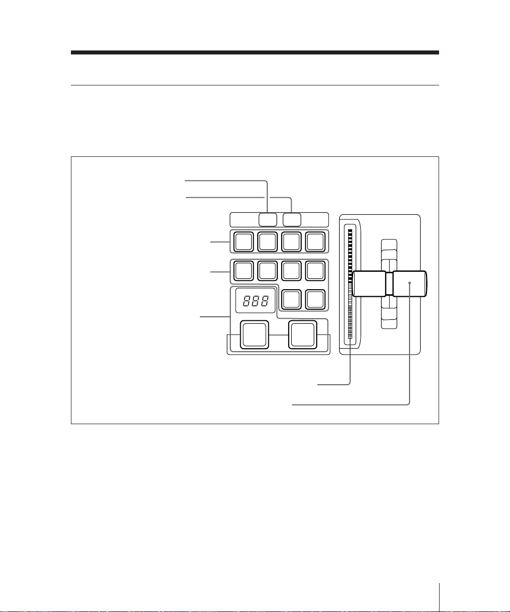
Mix/Effects Banks
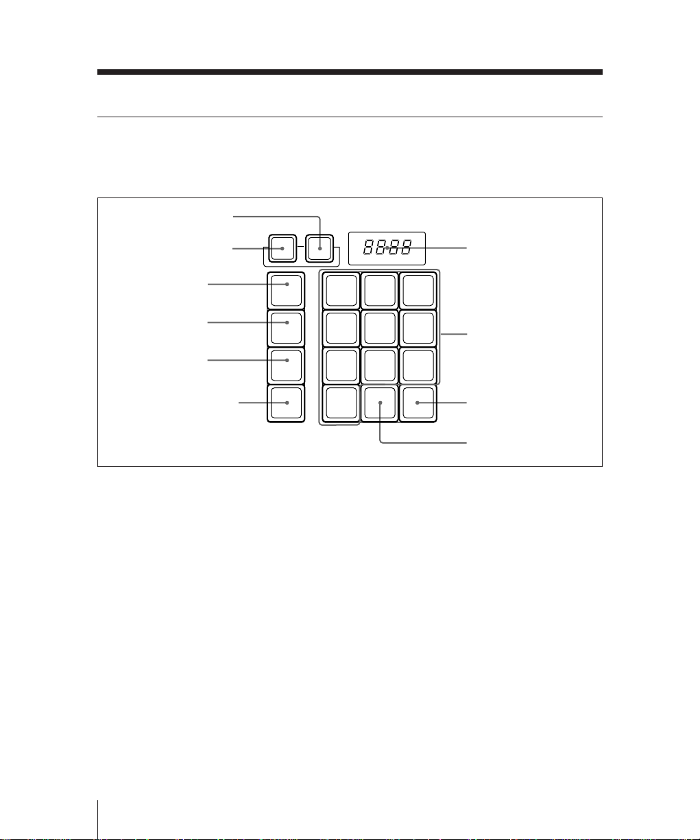
FlexiPad™
The FlexiPad™ is used for saving and
recalling snapshots1) of this M/E bank.
1 KEY DSBL button
2 XPT DSBL button
XPT
DSBL
KEY
DSBL
7 Numeric display
3 SHIFT button
4 DME button
5 WIPE button
6 SNAPSHOT button
SHIFT
DME
WIPE
SNAP
SHOT
FlexiPad™
1 KEY DSBL (disable) button
Press this button, turning it on, to apply the
“KEY DISABLE” attribute to the M/E
snapshot next to be recalled. This means
that recalling the snapshot will not change
the current key settings on this M/E bank.
78
4
12
EFF
0
DISS
9
56
3
AUTO
TRANS
8 Numeric keys
9 AUTO TRANS button
!º EFF DISS button
2 XPT DSBL (cross-point disable)
button
Press this button, turning it on, to apply the
“XPT DISABLE” attribute to the M/E
snapshot next to be recalled. This means
that recalling the snapshot will not change
the current signal selections on
background buses A and B on this M/E
bank.
..............................................................................................................................................................................
1) The snapshot function allows you to save a
collection of switcher settings in memory, and
recall them as necessary to use the same settings
2-14
Chapter 2 Location and Function of Parts
again. The collection of settings saved in memory
is itself referred to as a snapshot.
For more details of snapshot operations, see
Chapter 7.

3 SHIFT button
Use this button in combination with the
numeric keypad in the FlexiPad when
saving and recalling snapshots.
4 DME button
Use this button when saving or recalling a
DME wipe snapshot.
5 WIPE button
Use this button when saving or recalling a
wipe snapshot.
6 SNAPSHOT button
Use this button when saving or recalling
an M/E snapshot, and also in combination
with the key snapshot buttons in the key
control section when saving or recalling a
key snapshot.
7 Numeric display
• While you are saving or recalling an M/E
snapshot, this shows the snapshot register
number.
• While you are saving or recalling a wipe
or DME wipe snapshot, this shows the
pattern number.
9 AUTO TRANS (transition) button
Press this button, turning it on, to save an
M/E snapshot with the “AUTO
TRANSITION” attribute. Recalling a
snapshot saved with this attribute will
immediately start an auto transition on this
M/E bank.
!º EFF DISS (effect dissolve) button
Press this button, turning it on, to save an
M/E snapshot with the “EFFECT
DISSOLVE” attribute. Recalling a
snapshot saved with this attribute will
cause a smooth change from the current
M/E bank settings to the settings in the
snapshot.
8 Numeric keys
• When saving or recalling an M/E
snapshot, use these keys to specify the
snapshot register number.
• Also when saving or recalling a wipe or
DME wipe snapshot, use this to specify
the register number.
To return to the state before recalling a
wipe or DME wipe snapshot, press the 0
key.
Chapter 2 Location and Function of Parts
2-15
 Loading...