

Sony DSR-80, DSR-80P, DSR-60, DSR-60P Installation Manual
DIGITAL VIDEOCASSETTE RECORDER
DSR-80
DSR-80P
DIGITAL VIDEOCASSETTE PLAYER
DSR-60
DSR-60P
INSTALLATION MANUAL
DSR-80
DSR-80P
DSR-60 Printed in Japan
DSR-60P (UC, CE, ) 1997. 5 16
9-977-694-02 Image & Sound Communication Company
Sony Corporation
1997
Published by
Engineering Services Dept.
1st Edition (Revised 1)

SAFETY CHECK-OUT
After correcting the original service problem, perform the
following safety checks before releasing the set to the
customer :
Check the metal trim, “metallized” knobs, screws, and all
other exposed metal parts for AC leakage. Check leakage
as described below.
The material contained in this manual consists of
information that is the property of Sony Corporation and
is intended solely for use by the purchasers of the
equipment described in this manual.
Sony Corporation expressly prohibits the duplication of
any portion of this manual or the use thereof for any
purpose other than the operation or maintenance of the
equipment described in this manual without the express
written permission of Sony Corporation.
LEAKAGE TEST
The AC leakage from any exposed metal part to earth
ground and from all exposed metal parts to any exposed
metal part having a return to chassis, must not exceed 0.5
mA (500 microampers). Leakage current can be measured
by any one of three methods.
1. A commercial leakage tester, such as the Simpson 229
or RCA WT-540A. Follow the manufacturers’
instructions to use these instruments.
2. A battery-operated AC milliammeter. The Data
Precision 245 digital multimeter is suitable for this job.
3. Measuring the voltage drop across a resistor by means
of a VOM or battery-operated AC voltmeter. The
“limit” indication is 0.75 V, so analog meters must
have an accurate low-voltage scale. The Simpson 250
and Sanwa SH-63Trd are examples of a passive VOM
that is suitable. Nearly all battery operated digital
multimeters that have a 2 V AC range are suitable. (See
Fig. A)
Le matériel contenu dans ce manuel consiste en
informations qui sont la propriété de Sony Corporation
et sont destinées exclusivement à l'usage des
acquéreurs de l'équipement décrit dans ce manuel.
Sony Corporation interdit formellement la copie de
quelque partie que ce soit de ce manuel ou son emploi
pour tout autre but que des opérations ou entretiens
de l'équipement à moins d'une permission écrite de
Sony Corporation.
Das in dieser Anleitung enthaltene Material besteht aus
Informationen, die Eigentum der Sony Corporation sind,
und ausschließlich zum Gebrauch durch den Käufer der
in dieser Anleitung beschriebenen Ausrüstung bestimmt
sind.
Die Sony Corporation untersagt ausdrücklich die Vervielfältigung jeglicher Teile dieser Anleitung oder den
Gebrauch derselben für irgendeinen anderen Zweck als
die Bedienung oder Wartung der in dieser Anleitung
beschriebenen Ausrüstung ohne ausdrückliche schriftliche Erlaubnis der Sony Corporation.
To Exposed Metal
Parts on Set
AC
0.15 µF
1.5 k Ω
Earth Ground
voltmeter
(0.75 V)
Fig A. Using an AC voltmeter to check AC leakage.

Introducing this manual
Related manuals
This manual is the installation manual of the digital videocassette recorder model DSR-80/80P
and the digital videocassette player model DSR-60/60P.
This manual contains rack mount information necessary for installation of the equipment,
the connector information necessary for connecting the unit with peripherals and others.
In addition to this Installation Manual, the following manuals are provided.
• Operating Instructions (Supplied with equipment)
Parts number : 3-859-358-11 (English, for UC, CE)
3-859-358-21 (French, for UC, CE)
3-859-358-31 (German, for CE)
3-859-358-41 (Italian, for CE)
Explains how to operate this equipment.
• Service Manual vol. 1 (Not supplied with equipment)
Parts number : 9-977-696-12
Contains the maintenance information and servicing information necessary for parts
replacement and adjustment.
• Service Manual vol. 2 (Not supplied with equipment)
Parts number : 9-977-696-21, 9-977-696-81
Contains the block diagrams, board layouts, schematic diagrams and parts lists.


TABLE OF CONTENTS
INSTALLATION
1. Installation Procedure .......................................................... 1
2. Operational Environment..................................................... 1
3. Operating Voltage................................................................ 1
4. Installation Space................................................................. 2
5. Supplied Accessories ........................................................... 2
6. Optional Accessories ........................................................... 2
7. Rack Mounting..................................................................... 3
8. Connection of Editing Equipment, and Input/Output Signals
of Connectors ....................................................................... 5
8-1. Connection of Editing Equipment............................... 5
8-2. Matching Connectors .................................................. 9
8-3. Input/Output Signals of the Connectors .................... 10
9. Installation Setup and Adjustment..................................... 13
9-1. Switch Settings on the Connector Panel ................... 13
9-2. Setting on the Front Panel Unit ................................. 13
9-3. On-board Switch Setting ........................................... 14
9-4. System Adjustment After Installation ....................... 16
9-5. Connection of Editor Controller ............................... 16
10. Setup Check Sheet ............................................................. 18
–1–

INSTALLATION
Be sure to install the DSR-80/80P/60/60P in location satisfying the required operational environment described below
to assure the DSR-80/80P/60/60P superior performance and to maintain the excellent serviceability and accessibility.
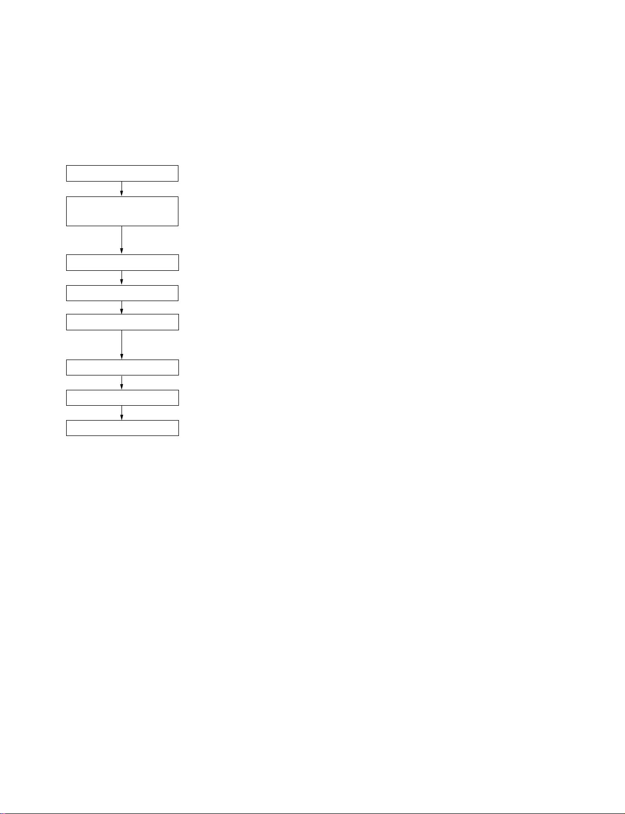
1. INSTALLATION PROCEDURE
START
DETERMINATION OF
INSTALLATION PLACE
UNPACKING
RACK MOUNTING
CONNECTORS
INITIAL SETUP
OPERATION CHECK
END
· · · 2. OPERATIONAL ENVIRONMENT
· · · 3. OPERATING VOLTAGE
· · · 4. INSTALLATION SPACE
· · · 5. SUPPLIED ACCESSORIES
· · · 7. RACK MOUNTING
· · · 8-2. MATCHING CONNECTORS
· · · 8-3. INPUT/OUTPUT SIGNALS OF THE CONNECTORS
· · · 9. INSTALLATION SETUP AND ADJUSTMENT
· · · If an error message is shown on the time counter, refer to
“3-3. ERROR MESSAGE” in SERVICE MANUAL VOL. 1.
2. OPERATIONAL ENVIRONMENT
. Operating temperature : +5 dC to +40 dC
. Humidity : 80 % or less
. Storage temperature : _20 dC to +60 dC
. Locations to avoid : . Areas where the unit will be exposed to direct sunlight or any other strong lights.
. Dusty areas or areas where it is subject to vibration.
. Areas with strong electric or magnetic fields.
. Areas near heat sources.
(Good air circulation is essential to prevent internal heat build-up. Place the unit in
location with sufficient air circulation. Do not block the ventilation holes on the cabinet
and the rear panel.)
. Horizonal condition : within ±30 d
3. OPERATING VOLTAGE
. Power voltage : AC 100 V to 120 V/NTSC
AC 200 V to 240 V/PAL
. Power frequency : 50/60 Hz
. Power consumption : NTSC (UC) : 85 W/DSR-60, 140 W/DSR-80
PAL (CE) : 87 W/DSR-60P, 145 W/DSR-80P
1
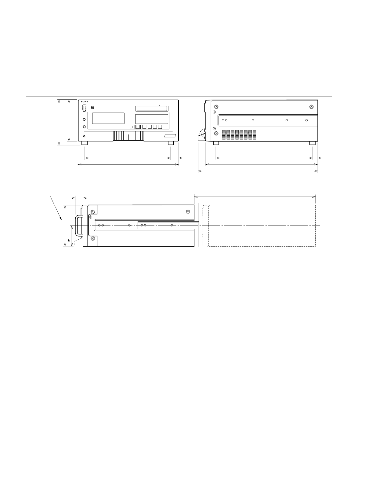
4. INSTALLATION SPACE
(1) The rear side must be at least 40 cm away from the walls for ventilation and maintenance.
(2) When the unit is operated on a desk or similar condition, assure that the clearance above the unit is at least 40 cm to provide accessibility
to the printed circuit boards and other mechanical parts. Note that it is not necessary to provide the space when the unit is mounted in a
rack since the printed circuit boards can be repaired after it is pulled out.
191
174 (4U)
Set’s height at
( )
rack mounting.
174
(height as slide rail center)
30 (handle hight)
87
5. SUPPLIED ACCESSORIES
. AC power cord : (1)
. RCC-5G 9-pin remote cable : (1)
. Operating instructions : (1)
. ClipLink™ Guide : (1)
372
427
27.5
when rack-mounted
400
494
512
577 (maximum traveling distance)
44
Unit : mm
6. OPTIONAL ACCESSORIES
. TBC remote control unit : UVR-60/60P
. Rack mount Kit : RMM-130
(The unit can be mounted in a 19-inch standard rack)
. Remote control cable : RCC-5G/10G/30G
. Cleaning cassette tape : PDVM-12CL
. Circus Remote control : SVRM-100A/DSRM-10
. Digital video cassette (Mini size) : PDVM-12ME/22ME/32ME/40ME
. Digital video cassette (Standard size) : PDV-64ME/94ME/124ME/184ME
. SDI output board : DSBK-100/100P (DSR-60/60P)
. QSDI output board : DSBK-110/110P (DSR-60/60P)
. SDI input/output board : DSBK-120/120P (DSR-80/80P)
. Time code input/output board : DSBK-130/130P
2
 Loading...