

Sony DSR-570WS, DSR-570WSP Service Manual

DIGITAL CAMCORDER
DSR-570WS
DSR-570WSP
DSR-500WS
DSR-500WSP
SERVICE MANUAL
Volume 2 1st Edition (Revised 1)

! W ARNING
This manual is intended for qualified service personnel only.
To reduce the risk of electric shock, fire or injury, do not perform any servicing other than that
contained in the operating instructions unless you are qualified to do so. Refer all servicing to
qualified service personnel.
! W ARNUNG
Die Anleitung ist nur für qualifiziertes Fachpersonal bestimmt.
Alle Wartungsarbeiten dürfen nur von qualifiziertem Fachpersonal ausgeführt werden. Um die
Gefahr eines elektrischen Schlages, Feuergefahr und Verletzungen zu vermeiden, sind bei
Wartungsarbeiten strikt die Angaben in der Anleitung zu befolgen. Andere als die angegeben
Wartungsarbeiten dürfen nur von Personen ausgeführt werden, die eine spezielle Befähigung
dazu besitzen.
! AVERTISSEMENT
Ce manual est destiné uniquement aux personnes compétentes en charge de l’entretien. Afin
de réduire les risques de décharge électrique, d’incendie ou de blessure n’effectuer que les
réparations indiquées dans le mode d’emploi à moins d’être qualifié pour en effectuer d’autres.
Pour toute réparation faire appel à une personne compétente uniquement.
DSR-570WS/570WSP/500WS/500WSP V2
/ Table of Contents
............................................................................................................ 5 (J)
..................................................................................................... 5 (J)
....................................................................................................................... 7 (J)
Manual Structure
Purpose of this manual ........................................................................................ 5 (E)
Related manuals................................................................................................... 5 (E)
Contents ............................................................................................................... 7 (E)
1. Spare Parts
1-1. ........................................................................................1-1
1-1. Notes on Repair Parts ..................................................................................1-1
1-2. Exploded Views ..........................................................................................1-2
1-3. Electrical Parts List ...................................................................................1-24
1-4. Supplied Accessories List .......................................................................1-128
1-5. Optional Fixtures List .............................................................................1-129
2. Semiconductor Pin Assignments
Index............................................................................................................ 2-1
Transistor.....................................................................................................2-8
IC.................................................................................................................2-8
3. Block Diagrams
Index............................................................................................................ 3-1
Camera Overall ...........................................................................................3-2
VTR Overall (1/2) .......................................................................................3-4
VTR Overall (2/2) .......................................................................................3-5
VA-190........................................................................................................ 3-6
DPR-141B/141 (1/3) ................................................................................... 3-8
CP-373/315 (1/7), ES-26 (1/3)
DPR-141B/141 (2/3) ................................................................................. 3-10
DPR-141B/141 (3/3) ................................................................................. 3-11
ES-26 (2/3) ................................................................................................3-12
ES-26 (3/3) ................................................................................................3-13
CN-2277/1519, CP-373/315 (2/7) (3/7) (4/7)
DSR-570WS/570WSP/500WS/500WSP V2
1

AT-150B SE-511 ..................................................................................... 3-14
AT-127 SE-511 ........................................................................................3-15
Audio (1/2) ................................................................................................ 3-16
CP-373/315 (5/7), FP-118A/118 (1/4), SW-19
Audio (2/2) ................................................................................................ 3-17
AA-104, CP-373/315 (6/7), CN-1867, FP-118A/118 (2/4), LE-221 (2/2)
System Control (1/2) ................................................................................. 3-18
FP-118A/118 (3/4), KY-405, LE-221 (1/2)
System Control (2/2) ................................................................................. 3-19
CP-373/315 (7/7), FP-118A/118 (4/4), FP-99, SW-929
RP-91.........................................................................................................3-20
Servo (1/3).................................................................................................3-21
CC-68, HN-227 (1/3), MT-114 (1/2), SE-295, SE-297, SV-213 (1/3)
Servo (2/3).................................................................................................3-22
HN-227 (2/3), SV-213 (2/3)
Servo (3/3).................................................................................................3-23
DU-36, HN-227 (3/3), MB-833, MT-114 (2/2), SV-213 (3/3)
DV-21C/21 ................................................................................................3-24
VE-44 ........................................................................................................3-25
4. Schematic Diagrams and Frame Wiring
Index............................................................................................................4-1
Frame Wiring ..............................................................................................4-3
PA-254 (B) .................................................................................................. 4-4
PA-255 (G) ..................................................................................................4-4
PA-256 (R) .................................................................................................. 4-4
PA-219 (B) .................................................................................................. 4-5
PA-220 (G) ..................................................................................................4-5
PA-221 (R) .................................................................................................. 4-5
TG-204 ........................................................................................................4-6
VA-190......................................................................................................4-10
DPR-141B/141 ..........................................................................................4-16
ES-26 .........................................................................................................4-34
AT-150B ................................................................................................... 4-42
SE-511 .......................................................................................................4-42
AT-127 ......................................................................................................4-46
CN-1811 ....................................................................................................4-49
FP-118A/118 ............................................................................................. 4-50
KY-405......................................................................................................4-50
FP-99 ......................................................................................................... 4-59
GCN-16 ..................................................................................................... 4-59
SW-929 ..................................................................................................... 4-59
2
DSR-570WS/570WSP/500WS/500WSP V2

RP-91.........................................................................................................4-60
SE-298.......................................................................................................4-64
SV-213 ......................................................................................................4-64
CC-68 ........................................................................................................ 4-72
HN-227...................................................................................................... 4-72
MT-114 .....................................................................................................4-72
SE-295.......................................................................................................4-72
SE-297.......................................................................................................4-72
AA-104...................................................................................................... 4-73
CN-1866....................................................................................................4-73
CN-1867....................................................................................................4-73
LE-221.......................................................................................................4-73
SW-18 .......................................................................................................4-73
CN-1864....................................................................................................4-74
CN-1865....................................................................................................4-74
PSW-71 ..................................................................................................... 4-74
SW-19 .......................................................................................................4-74
CP-373.......................................................................................................4-75
CN-2277....................................................................................................4-80
CP-315.......................................................................................................4-81
CN-1519....................................................................................................4-83
CN-1873....................................................................................................4-83
CN-1874....................................................................................................4-83
PS-570 .......................................................................................................4-83
CN-1823....................................................................................................4-84
DV-21C/21................................................................................................4-84
VE-44 ........................................................................................................ 4-86
MB-833 ..................................................................................................... 4-88
DU-36........................................................................................................ 4-90
5. Board Layouts
Index............................................................................................................ 5-1
AA-104........................................................................................................ 5-2
AT-150 ........................................................................................................ 5-3
AT-127 ........................................................................................................ 5-4
CC-68 .......................................................................................................... 5-5
CN-1823......................................................................................................5-5
CN-1864......................................................................................................5-5
CN-2277......................................................................................................5-5
CN-1865......................................................................................................5-6
CN-1866......................................................................................................5-6
DSR-570WS/570WSP/500WS/500WSP V2
3

CN-1867 ......................................................................................................5-6
CN-1873 ......................................................................................................5-6
CN-1874 ......................................................................................................5-6
CN-1519 ......................................................................................................5-7
DU-36..........................................................................................................5-7
DV-21..........................................................................................................5-7
CP-373.........................................................................................................5-8
CP-315.........................................................................................................5-9
DPR-141....................................................................................................5-10
ES-26 .........................................................................................................5-12
FP-118 ....................................................................................................... 5-14
FP-99 ......................................................................................................... 5-17
GCN-16 ..................................................................................................... 5-17
PA-219 ...................................................................................................... 5-18
PA-220 ...................................................................................................... 5-18
PA-221 ...................................................................................................... 5-18
PA-254 ...................................................................................................... 5-18
PA-255 ...................................................................................................... 5-18
PA-256 ...................................................................................................... 5-18
KY-405......................................................................................................5-20
LE-221.......................................................................................................5-20
RP-91.........................................................................................................5-20
HN-227......................................................................................................5-21
MT-114 ..................................................................................................... 5-21
SE-295 .......................................................................................................5-21
SE-297 .......................................................................................................5-21
PS-570 ....................................................................................................... 5-22
PSW-71 .....................................................................................................5-22
SE-511 .......................................................................................................5-22
MB-833 .....................................................................................................5-23
SV-213 ...................................................................................................... 5-24
SW-18 ....................................................................................................... 5-26
SW-19 ....................................................................................................... 5-26
SW-929 ..................................................................................................... 5-26
VE-44 ........................................................................................................5-26
TG-204 ......................................................................................................5-27
VA-190......................................................................................................5-28
4
DSR-570WS/570WSP/500WS/500WSP V2
DSR-570WS/570WSP/500WS/500WSP V2
5 (J)
6 (J)
DSR-570WS/570WSP/500WS/500WSP V2
DSR-570WS/570WSP/500WS/500WSP V2
7 (J)


Purpose of this manual
Related manuals
Manual Structure
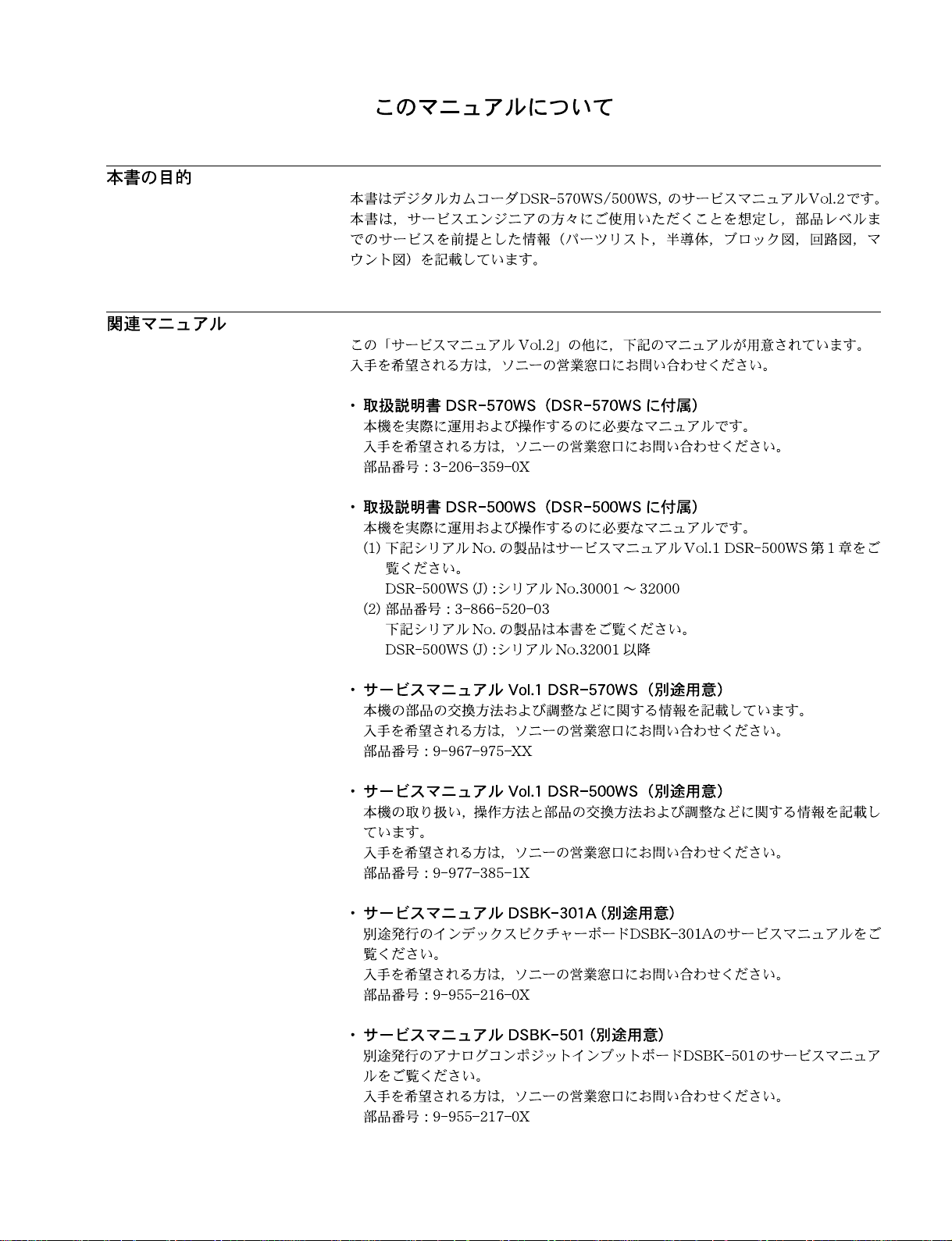
This manual is the Service Manual Vol. 2 of the digital camcorder DSR-570WS/
570WSP/500WS/500WSP.
This manual is intended for use by trained sevice enginneers, and describes information (parts lists, semiconductor pin assignments, block diagrams, schematic diagrams and board layouts) on the premise of component level service.
Besides to this Service Manual Vol. 2, the following manuals are provided.
For obtaining, contact your local Sony Sales Office/Service Center.
. Operating Instructions DSR-570WS/570WSP
(Supplied with the DSR-570WS/570WSP)
This manual is necessary for the installation and the operation of this unit.
For obtaining, contact your local Sony Sales Office/Service Center.
Part No. 3-206-359-1X
..
. Instruction Manual DSR-500WS/500WSP
..
(Supplied with the DSR-500WS/500WSP)
This manual is required for the proper operation and application of this unit.
(1) For the products of following Serial No. , please see the Section 1 of
DSR-500WS/500WSP service manual volume 1.
DSR-500WS (UC) : Serial No.10001 through 12000
DSR-500WSP (CE) : Serial No.40001 through 42000
(2) Part No. 3-866-520-13
For the products of following Serial No., please see this manual.
DSR-500WS (UC) : Serial No.12001 and Higher
DSR-500WSP (CE) : Serial No.42001 and Higher
..
. Service Manual Vol. 1 DSR-570WS/570WSP (Available on request)
..
Contains the instruction manual related to the operations of this unit, the replacement of the parts and adjustments.
For obtaining, contact your local Sony Sales Office/Service Center.
Part No. 9-967-976-XX
..
. Service Manual Vol. 1 DSR-500WS/500WSP (Available on request)
..
Contains the instruction manual related to the operations of this unit, the replacement of the parts and adjustments.
For obtaining, contact your local Sony Sales Office/Service Center.
Part No. 9-977-384-1X
. Service Manual DSBK-301A (Available on request)
See the index picture board DSBK-301A service manual available separately.
For obtaining, contact your local Sony Sales Office/Service Center.
Part No. 9-955-216-0X
. Service Manual DSBK-501/501P (Available on request)
See the analog composite input board DSBK-501/501P service manual available
separately.
For obtaining, contact your local Sony Sales Office/Service Center.
Part No. 9-955-217-0X
DSR-570WS/570WSP/500WS/500WSP V2
5 (E)

..
.
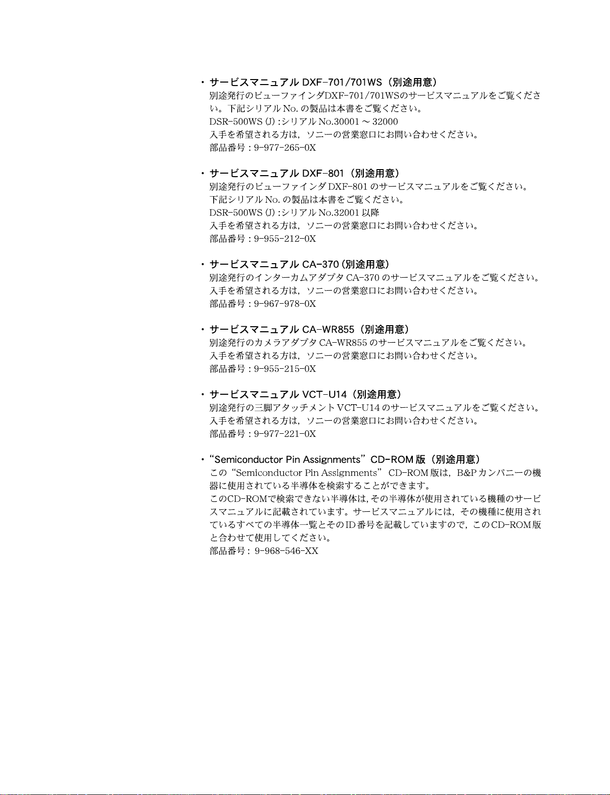
Service Manual DXF-701/701CE/701WS/701WSCE (Available on request)
..
See the viewfinder DXF-701/701CE/701WS/701WSCE service manual available
separately.
For the products of following Serial No., please see this manual.
DSR-500WS (UC) : Serial No.10001 through 12000
DSR-500WSP (CE) : Serial No.40001 through 42000
For obtaining, contact your local Sony Sales Office/Service Center.
Part No. 9-977-265-0X
..
. Service Manual DXF-801/801CE (Available on request)
..
See the viewfinder DXF-801/801CE service manual available separately.
For the products of following Serial No.,please see this manual.
DSR-500WS (UC) : Serial No.12001 and Higher
DSR-500WSP (CE) : Serial No.42001 and Higher
For obtaining, contact your local Sony Sales Office/Service Center.
Part No. 9-955-212-0X
. Service Manual CA-370 (Available on request)
See the intercom adaptor CA-370 service manual available separately.
For obtaining, contact your local Sony Sales Office/Service Center.
Part No. 9-967-978-0X
..
. Service Manual CA-WR855 (Available on request)
..
See the CA-WR855 service manual available separately.
For obtaining, contact your local Sony Sales Office/Service Center.
Part No. 9-955-215-0X
..
. Service Manual VCT-U14 (Available on request)
..
See the tripod adaptor VCT-U14 service manual available separately.
For obtaining, contact your local Sony Sales Office/Service Center.
Part No. 9-977-221-0X
..
. “Semiconductor Pin Assignments” CD-ROM (Available on request)
..
This “Semiconductor Pin Assignments” CD-ROM allows you to search for
semiconductors used in B&P Company equipment.
Semiconductors that cannot be searched for on this CD-ROM are listed in the
service manual for the corresponding unit. The service manual contains a complete list of all semiconductors and their ID Nos., and thus should be used together
with the CD-ROM.
Part number: 9-968-546-XX
6 (E)
DSR-570WS/570WSP/500WS/500WSP V2

Contents
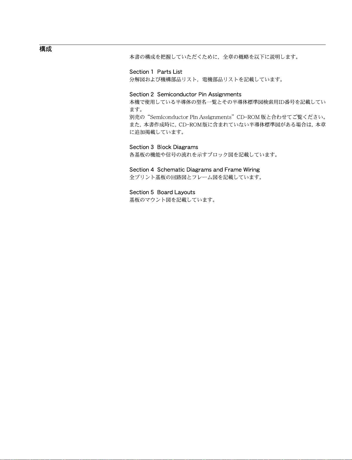
The following is a summary of all the sections for understanding the contents of
this manual.
Section 1 Parts List
Describes the exploded views, the mechanical parts list, and the electrical parts list.
Section 2 Semiconductor Pin Assignments
Contains information on semiconductors used for the unit.
It includes a complete list of the semiconductors and their ID Nos. for retrieving
information on “Semiconductor Pin Assignments” CD-ROM, which is available
separately.
Please refer to this section together with the “Semiconductor Pin Assignments”
CD-ROM.
Information on the semiconductors not contained in the CD-ROM at the time of
issue of this manual, if any, is given in this section as well.
Section 3 Block Diagrams
Describes the block diagrams which show each board function and signal flow.
Section 4 Schematic diagrams and Frame Wiring
Describes the schematic diagrams of all circuit boards and the frame wiring.
Section 5 Board Layouts
Describes the board layouts for the unit.
DSR-570WS/570WSP/500WS/500WSP V2
7 (E)

Section 1
Parts List
1-1. Notes on Repair Parts
1. Safety Related Components Warning
w
Components marked ! are critical to safe operation.
Therefore, specified parts should be used in the case of
replacement.
2. Standardization of Parts
Some repair parts supplied by Sony differ from those
used for the unit. These are because of parts
commonality and improvement.
Parts list has the present standardized repair parts.
3. Stock of Parts
Parts marked with “o” at SP (Supply Code) column of
the spare parts list may not be stocked. Therefore, the
delivery date will be delayed.
4. Harness
Harnesses with no part number are not registered as
spare parts.
In need of repair, get components shown in the list and
repair using them.
1-1.
DSR-570WS/570WSP/500WS/500WSP V2
1-1
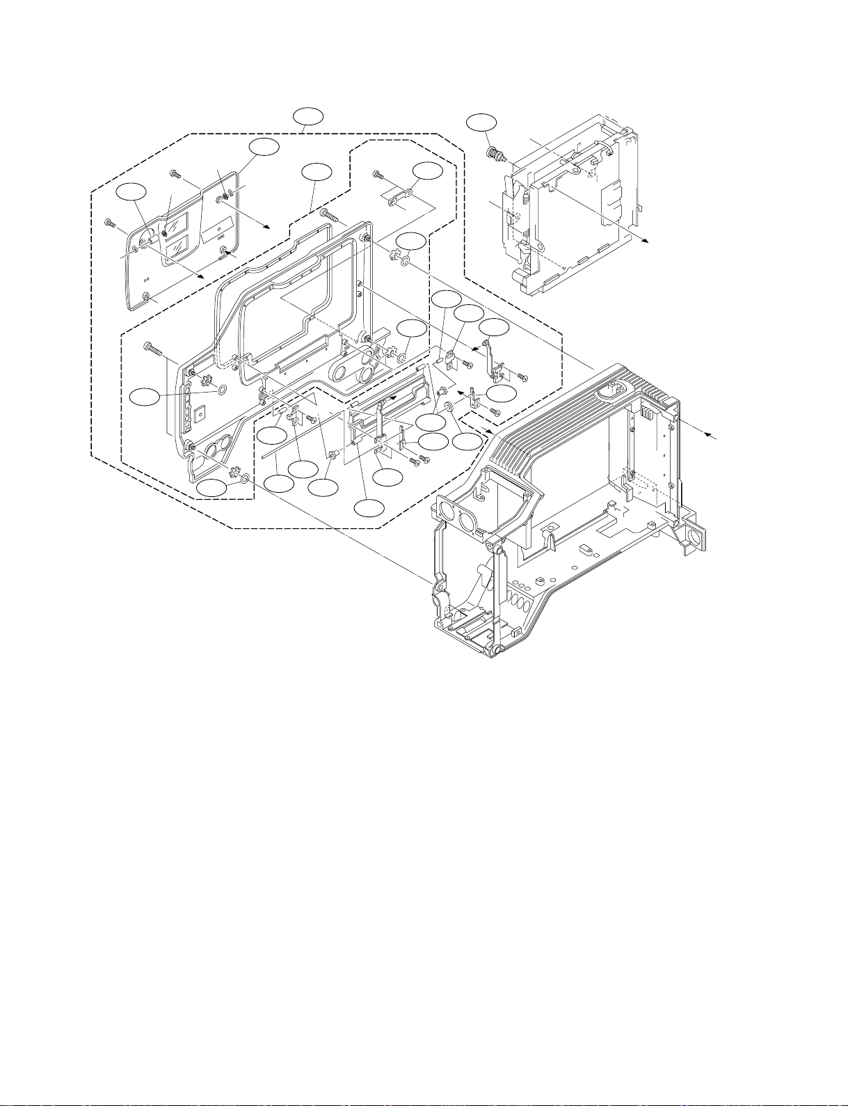
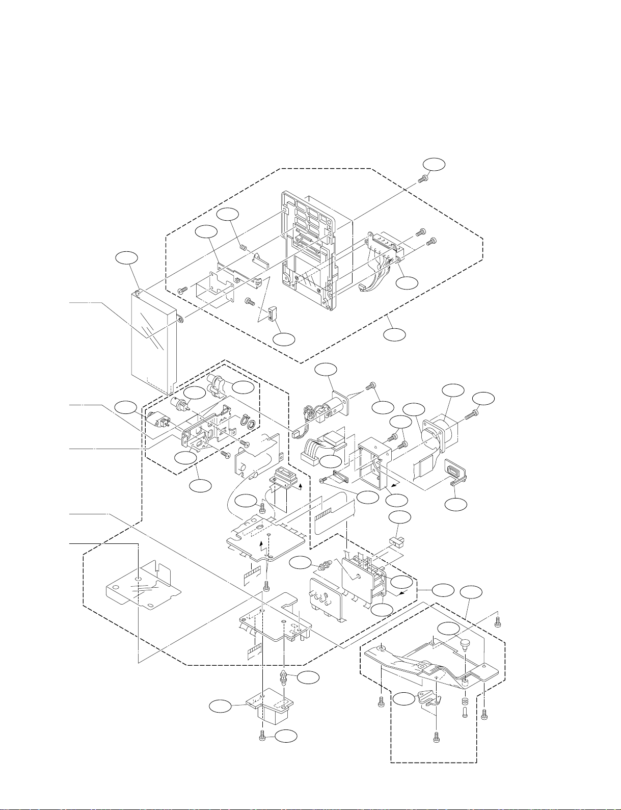
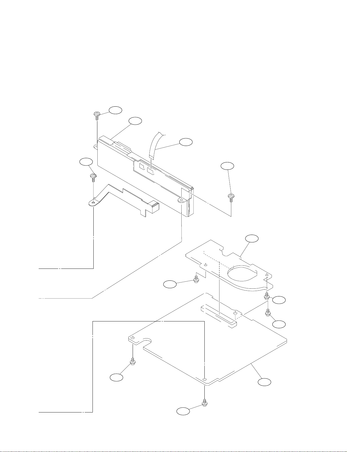
Left/Right Panel Block
1-2. Exploded Views
B2.6 x 5
29
B2.6 x 5
*5
B3 x 14
52
E1.5
E1.5
*3
52
LW3
*2
LW3
60
6
*6
*4
44
7
B2 x 4
23
25
P2.6 x 5
B3 x 14
24
34
LW3
LW3
12
*5
52
52
B2 x 4
39
24
27
B2 x 4
13
*4
*3
*1
44
23
5
*6
B2 x 4
*2
*1
43
26
B2 x 4
B2 x 4
*8
No. Part No. SP Description
*1,*2:For DSR-500WS/500WSP
*1:Serial No. 10001-12932(UC), 30001-32232(J),
40001-45215(CE)
*2:Serial No. 12933- (UC), 32233- (J), 45216- (CE)
No. Part No. SP Description
10 X-3605-489-7 s R PANEL(WS) SUB ASSEMBLY
[for DSR-500WS/500WSP]
X-3608-413-1 o SUB ASSY, R PANEL (B)
[for DSR-570WS/570WSP]
11 *2 X-3608-411-1 o SUB ASSY, KEY PANEL
1 A-8322-152-A o MOUNTED CIRCUIT BOARD, FP-118
[for DSR-500WS/500WSP]
A-8329-963-A s MOUNTED CIRCUIT BOARD, FP-118A
[for DSR-570WS/570WSP]
2 A-8318-188-A o MOUNTED CIRCUIT BOARD, KY-405
*1 X-3605-818-1 o SUB ASSEMBLY, KEY PANEL
[for DSR-500WS/500WSP]
12 X-3678-799-5 o SUPPORT L ASSEMBLY, ARM
13 X-3678-976-3 s SCREW ASSEMBLY, MD
14 1-473-406-12 s ENCODER, ED JOG
3 A-8322-170-A o MOUNTED CIRCUIT BOARD, GCN-16
4 A-8318-233-A o MOUNTED CIRCUIT BOARD, FP-99
5 X-3604-530-1 o SUPPORT L-M ASSEMBLY, ARM
15 1-544-559-11 s SPEAKER
16 1-550-414-31 o HOLDER, BATTERY
17 1-669-104-12 o PRINTED WIRING BOARD, SW-929
6 X-3604-535-4 s LID ASSEMBLY, CASSETTE COMPARTMENT
[for DSR-500WS/500WSP]
18 1-777-902-11 o CABLE, FLAT (10-CORE)
19 1-783-363-11 s CABLE, FLAT (10-CORE)
X-3608-412-1 s LID ASSY, CASSETTE COMPARTMENT
[for DSR-570WS/570WSP]
7 X-3605-487-5 o L PANEL(WS) SUB ASSEMBLY
[for DSR-500WS/500WSP]
X-3608-408-1 o SUB ASSY, L PANEL (WS)
[for DSR-570WS/570WSP]
20 3-176-488-01 s SHEET, VR
21 3-604-358-01 o KNOB(H), SW
22 3-604-373-03 o COVER, BATTERY
23 3-604-805-01 o CLAMP B, SHAFT
24 3-604-806-01 o SUPPORT, SHAFT
8 3-612-570-11 o PAD, R [for DSR-500WS/500WSP]
3-612-570-03 o PAD, R (ABS) [for DSR-570WS/570WSP]
9 X-3604-538-5 s COVER ASSEMBLY, FP
[for DSR-500WS/500WSP]
X-3608-410-1 s COVER ASSY, FP
25 3-604-889-01 o SHAFT R1, ARM
26 3-604-897-01 o FL, SUPPORT
27 3-604-898-01 o FR, SUPPORT
28 3-605-437-01 o SUPPORT, KNOB
[for DSR-570WS/570WSP]
1-2
DSR-570WS/570WSP/500WS/500WSP V2
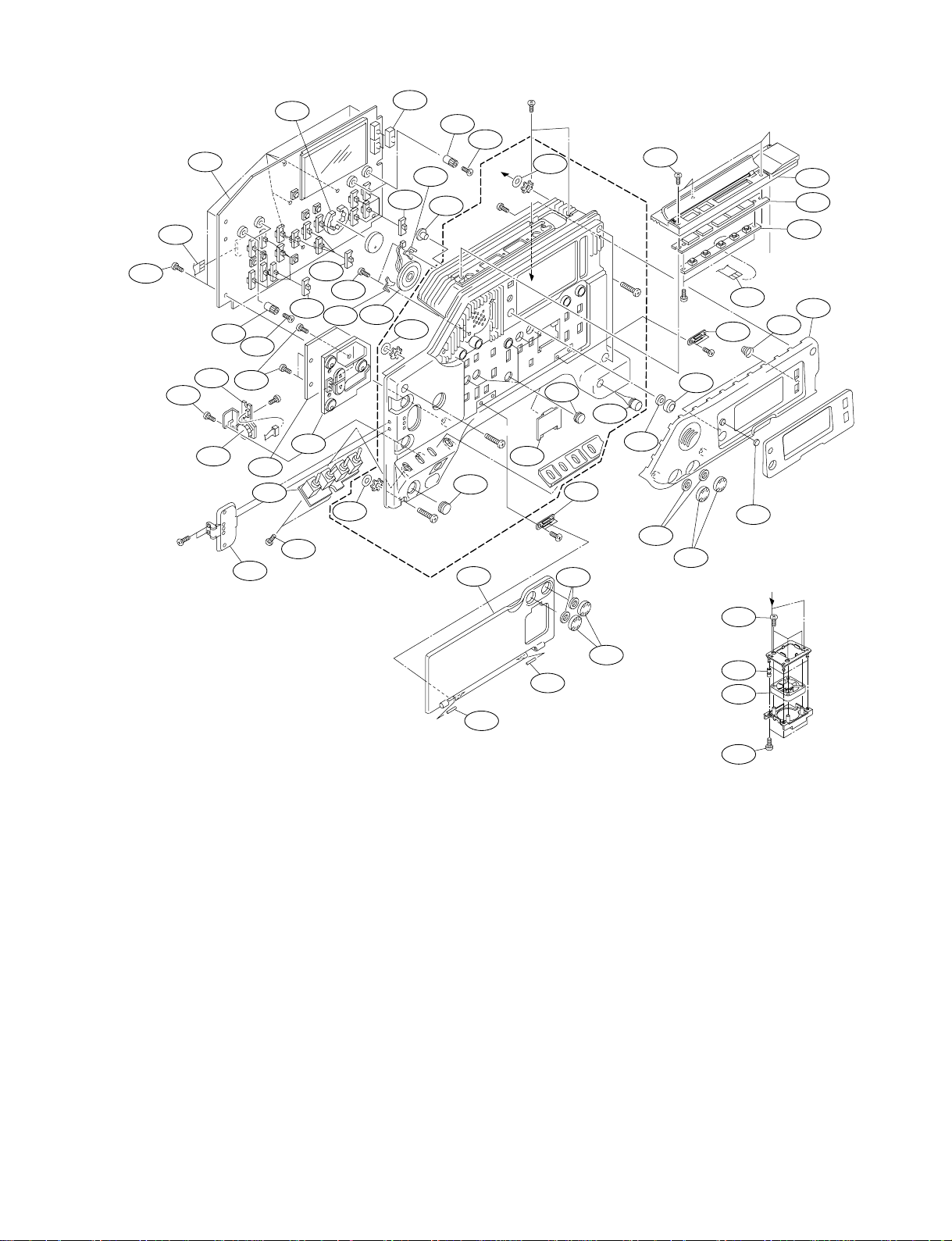
Left/Right Panel Block
51
B3 x 6
46
*8
BPT2.6 x 5
B3 x14
9
PS2 x 6
*7
22
52
LW3
B2 x 3
58
11
41
2
B3 x14
P2 x 4
B2 x 3
56
30
42
33
20
40
20
49
18
32
53
8
59
*7
LW3
21
28
48
31
47
15
52
LW3
36
B3 x14
16
1
19
31
51
31
48
50
46
17
51
51
14
B2 x 3
37
4
3
52
51
38
49
57
57
No. Part No. SP Description
29 3-605-946-01 o ROLLER, F
30 3-607-206-02 s FOOT, RUBBER
31 3-612-528-01 s KNOB(M), SW
32 3-612-529-01 s HINGE(F), FP
33 3-612-530-01 s HINGE(R), FP
34 3-612-572-02 o SUPPORT PANEL, SUB
[for DSR-500WS/500WSP]
3-612-572-21 o SUPPORT PANEL, SUB
[for DSR-570WS/570WSP]
36 3-612-632-02 s COVER, SW(H)
No. Part No. SP Description
50 3-744-304-01 s KNOB (SUPPORT)
51 3-625-924-01 s ALOCK SCREW, +B2.6 NI
52 3-672-250-01 s RING (M2.6), O
53 3-717-936-03 o COVER, LED
54 3-617-812-01 o VIBRATION PROOF, RUBBER
55 4-963-924-01 s SCREW (DAMPER)
56 3-672-244-21 s COVER, SWITCH
57 3-703-358-09 s PIN, PARALLEL (DIA. 2X25)
58 3-694-181-02 s SCREW, ALOCK PRECISION +P2.6X5
59 3-622-568-01 o SPRING, GROUND
37 3-612-674-01 s COVER, SWITCH
38 X-3605-488-1 s GUARD ASSEMBLY, SW
39 3-617-811-01 s HOLDER, CLAMP
60 A-8279-116-F o PANEL ASSY (WS), L
[for DSR-500WS/500WSP]
A-8279-673-A o PANEL ASSY (WS), L
40 3-679-086-01 s BUTTON, PUSH
[for DSR-570WS/570WSP]
41 3-679-501-01 o COVER, RUBBER KEY BOARD
42 3-686-086-01 s CUSHION, BUTTON
43 3-701-437-11 s WASHER
44 3-703-358-06 s PIN, PARALLEL (DIA. 2X14)
55
54
45
55
45 1-763-337-11 s MOTER, DC FAN
46 3-704-244-41 s SCREW (P1.7X3.0)
47 3-718-694-01 s PIN, PUSH BUTTON
48 3-724-726-01 o HOLDER, SPEAKER
49 3-724-755-04 s KNOB (F), VR
DSR-570WS/570WSP/500WS/500WSP V2
1-3
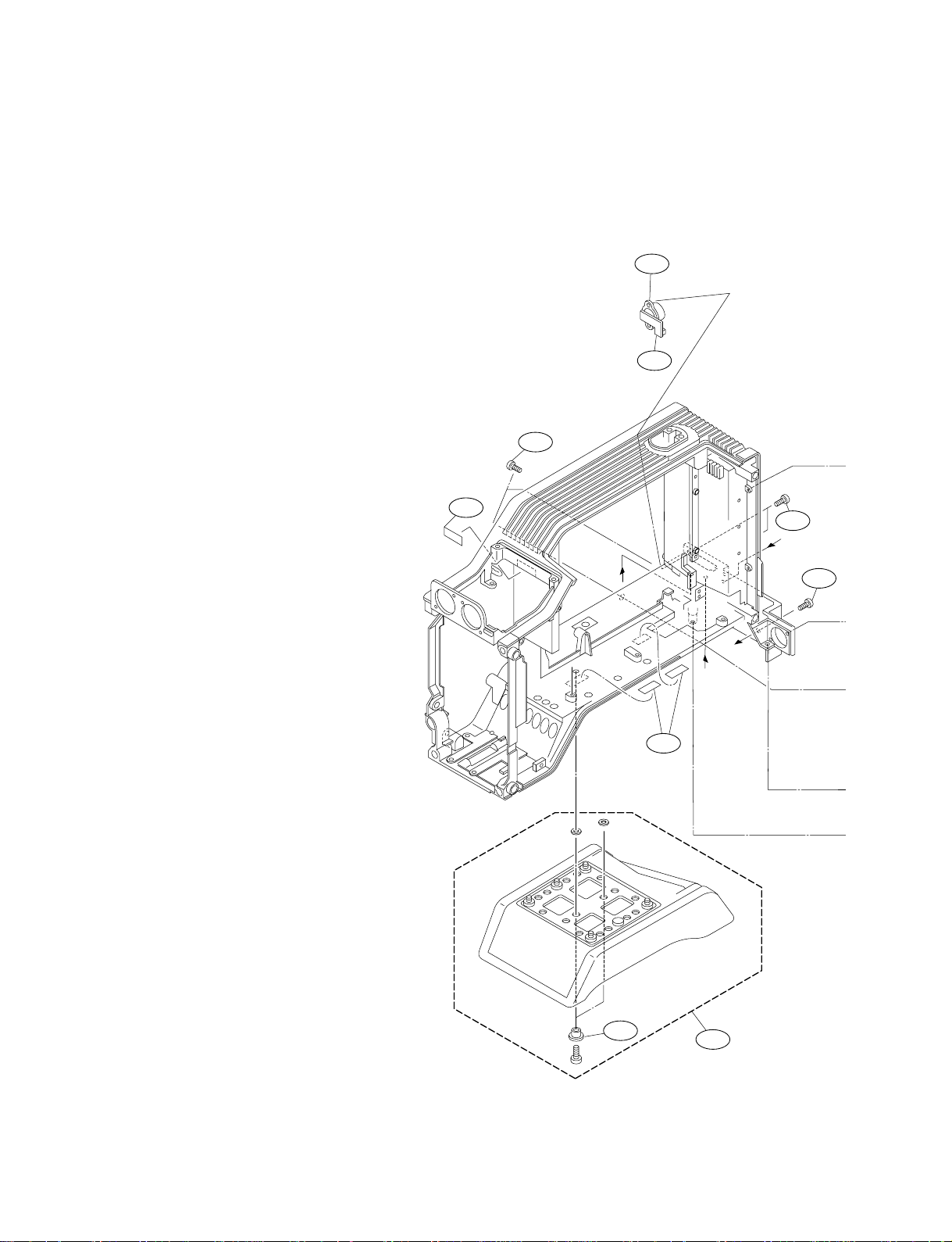
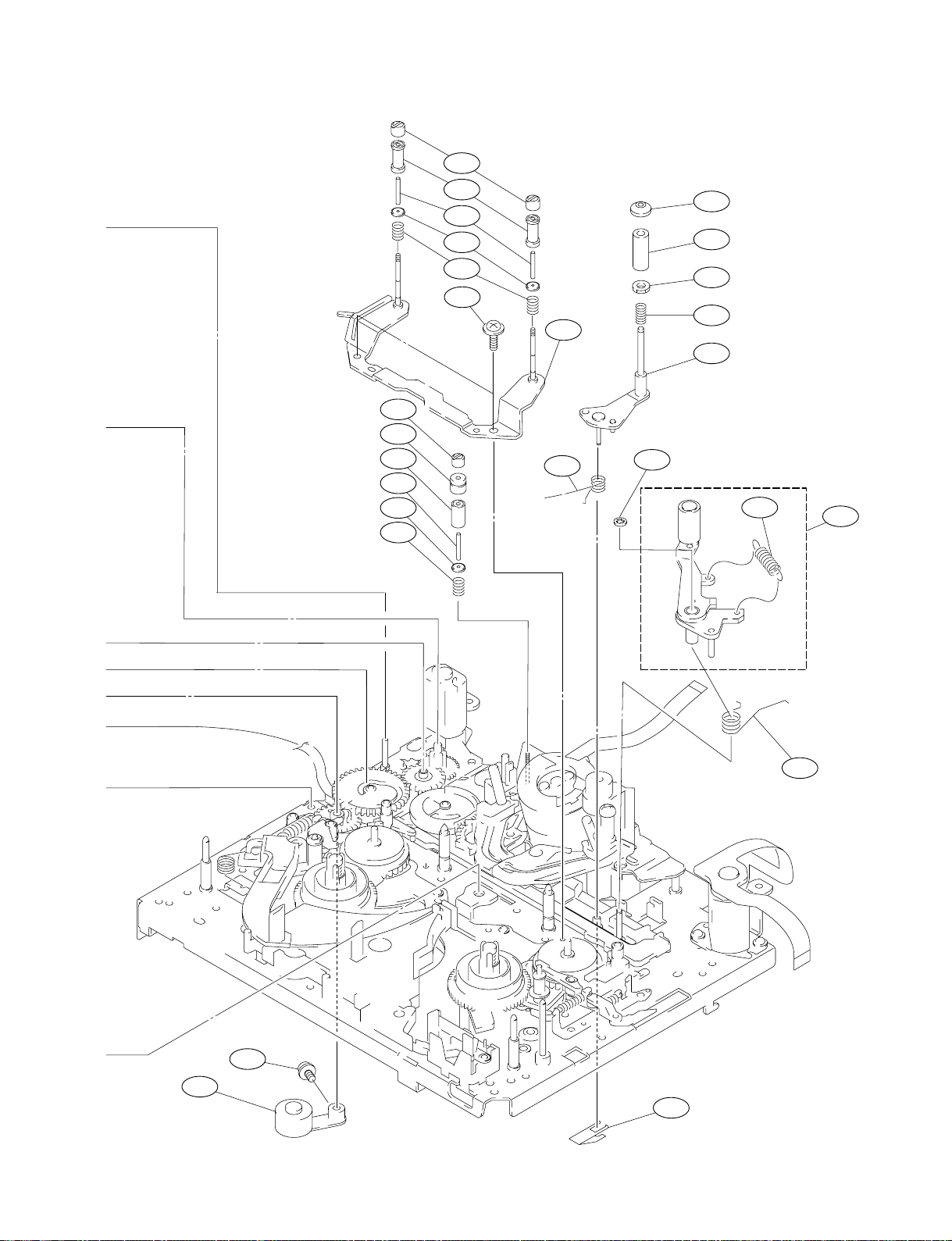
Bottom/Rear Frame
No. Part No. SP Description
101 A-8278-413-E s PLATE, CP ASSEMBLY
102 A-8278-790-C o PANEL ASSEMBLY, BOTTOM
[for DSR-500WS/500WSP]
A-8279-670-A o PANEL ASSY, BOTTOM (A)
[for DSR-570WS/570WSP]
103 A-8278-792-C o PANEL ASSEMBLY, REAR
104 A-8278-807-D o PAD ASSEMBLY, SHOULDER
105 A-8317-811-A o MOUNTED CIRCUIT BOARD, CN-1519
[for DSR-500WS/500WSP]
A-8329-788-A s MOUNTED CIRCUIT BOARD, CN-2277
[for DSR-570WS/570WSP]
106 A-8318-040-A o MOUNTED CIRCUIT BOARD, CP-315
[for DSR-500WS/500WSP]
A-8329-787-A s MOUNTED CIRCUIT BOARD, CP-373
[for DSR-570WS/570WSP]
107 A-8322-176-A o MOUNTED CIRCUIT BOARD, PS-570
108 A-8327-542-A s CONVERTER ASSY, DD
109 1-563-929-11 s CONNECTOR, 4P FEMALE “DC OUT”
110 1-572-042-11 s SWITCH, SLIDE
111 1-573-590-13 s CONNECTOR, S-TERMINAL 4P FEMALE “S VIDEO OUT”
112 1-673-955-11 o PRINTED WIRING BOARD, CN-1873
113 1-766-386-14 s CONNECTOR, XLR 3P FEMALE “AUDIO IN CH-1/CH2”
114 1-766-566-11 o CONNECTOR, 26P MALE “ EXT VTR”
115 1-778-787-13 s CONNECTOR, COAXIAL BNC “GENLOCK IN
/TC IN/TC OUT/MONITOR OUT”
116 1-778-788-12 s JACK, 2P “AUDIO OUT CH-1/CH-2”
117 1-958-497-11 s HARNESS, SUB (BATTERY)
118 3-604-359-01 o ADAPTOR, SW
119 3-604-376-01 o PLATE, CP
129
132
109
112
121
*1
*2
121
121 3-613-330-01 s SCREW, PRECISION +P2.6X6
122 3-613-650-01 s SPACER
123 3-679-648-02 o SPRING, COMPRESSION
124 3-679-688-02 o LEVER, RELEASE
125 3-680-952-01 o KNOB, RELEASE LEVER
126 3-711-703-01 o STOPPER
127 3-718-694-01 s PIN, PUSH BUTTON
128 3-729-076-01 s SCREW (+B 2X3)
129 3-846-067-21 o SPACER (C)
130 4-622-069-01 s SUPPORT, MODEM
131 1-958-496-12 s HARNESS, SUB (POWER LINE)
132 3-625-924-01 S ALOCK SCREW, +B2.6 NI
133 A-8322-181-B o MOUNTED CIRCUIT BOARD, CN-1823
134 3-617-827-01 s COVER, DV [for DSR-500WS/500WSP]
3-617-827-02 s COVER, DV [for DSR-570WS/570WSP]
W2.6
POLY
135 3-617-828-02 o BOX, DV [for DSR-500WS/500WSP]
3-617-828-11 o BOX, DV [for DSR-570WS/570WSP]
136 3-719-381-11 s SCREW (M2X5)
137 3-622-445-02 s SCREW, (+B3X18)
138 3-742-074-11 s SCREW (3)
B3 x 10
W2.6
POLY
122
*3
*4
129
104
1-4
DSR-570WS/570WSP/500WS/500WSP V2
108
124
Bottom/Rear Frame
138
123
P2.6 x 4
P2.6 x 4
111
P2 x 3
119
115
101
B3 x 8
P2 x 3
116
128
B3 x 8
*2
125
*4
130
131
133
136
121
103
135
117
114
137
105
136
*1
134
118
DSR-570WS/570WSP/500WS/500WSP V2
107
B2.6 x 6
132
130
110
*3
113
126
B3 x 5
BOLT HEXAGON SOCKET
2.6 x 6
106
127
102
B3 x 5
B3 x 5
1-5
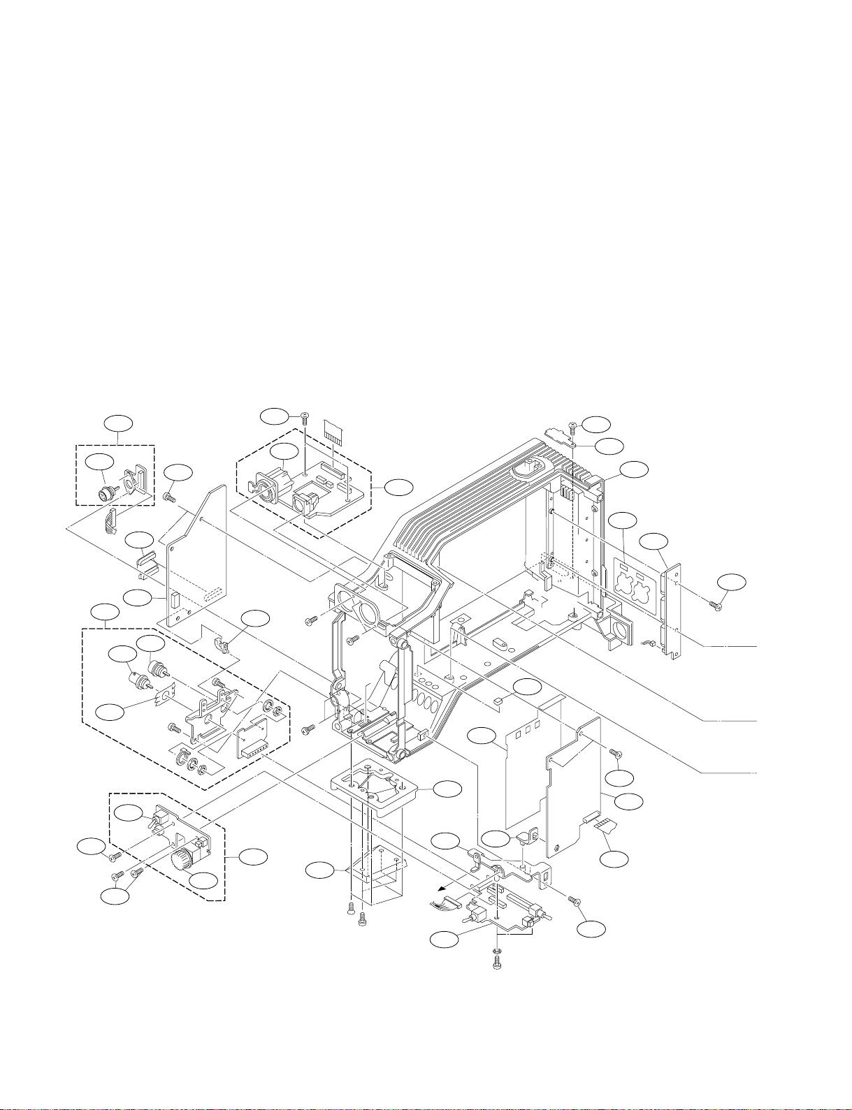
Front Frame/Chassis Block/Boards
No. Part No. SP Description
*1:For DSR-500WS/500WSP
*1:Serial No. 10001-12000(UC), 30001-32000(J), 40001-40850(CE)
No. Part No. SP Description
208 A-8322-167-A o MOUNTED CIRCUIT BOARD, CN-1864
209 A-8322-165-B o MOUNTED CIRCUIT BOARD, AA-104
210 A-8322-174-A o MOUNTED CIRCUIT BOARD, PSW-71
201 A-8322-150-B o MOUNTED CIRCUIT BOARD, MB-833
202 A-8322-183-A s MOUNTED CIRCUIT BOARD, DPR-141
[for DSR-500WS/500WSP]
A-8344-128-A s MOUNTED CIRSUIT BOARD, DPR-141B
[for DSR-570WS/570WSP]
203 A-8322-148-B o MOUNTED CIRCUIT BOARD, ES-26
[for DSR-570WS/500WS]
A-8322-194-B o MOUNTED CIRCUIT BOARD, ES-26(P)
211 A-8322-186-A o MOUNTED CIRCUIT BOARD, DV-21
[for DSR-500WS/500WSP]
A-8344-126-A s MOUNTED CIRCUIT BOARD, DV-21C
[for DSR-570WS/570WSP]
212 A-8322-359-A o MOUNTED CIRCUIT BOARD, VE-44
213 1-562-221-31 s CONNECTOR, 12P FEMALE “LENS”
214 1-562-382-31 s CONNECTOR, BNC “VIDEO OUT”
215 1-565-443-11 s CONNECTOR, 10P FEMALE “REMOTE”
[for DSR-570WSP/500WSP]
204 A-8322-146-A o MOUNTED CIRCUIT BOARD, VA-190
205 A-8322-144-A o MOUNTED CIRCUIT BOARD, AT-127
[for DSR-500WS/500WSP]
A-8329-974-A s MOUNTED CIRCUIT BOARD, AT-150B
[for DSR-570WS/570WSP]
206 A-8322-177-A o MOUNTED CIRCUIT BOARD, SW-19
216 1-570-984-11 s SWITCH, TOGGLE
217 1-673-954-11 o PRINTED WIRING BOARD, DU-36
218 1-764-394-11 s
CONNECTOR, XLR 3P FEMALE “MIC IN +48V”
219 1-777-865-13 s CABLE, FLAT (40-CORE)
220 1-777-866-12 s CABLE, FLAT (45-CORE)
221 1-777-867-12 s CABLE, FLAT (50-CORE)
207 A-8322-168-A o MOUNTED CIRCUIT BOARD, CN-1865
241
218
209
213
208
241
239
235
244
241
207
230
241
214
216
226
205
215
B3 x 6
B3 x 6
232
242
206
PS2.6 x 6
PS2.6 x 6
237
K4 x 10
B2 x 5
P4 x 6
231
217
241
*2
*1
247
233
234
*1
210
LW 2.6
245
241
204
240
228
241
1-6
DSR-570WS/570WSP/500WS/500WSP V2
Front Frame/Chassis Block/Boards
203
229
241
225
219
236
219
222
201
223
224
241
221
220
211
243
212
243
202
243
229
241
246
*2
No. Part No. SP Description
222 1-783-282-14 s CABLE, FLAT (50-CORE)
223 1-783-283-13 s CABLE, FLAT (50-CORE)
224 1-790-768-11 s CABLE, FLAT (45-CORE)
225 1-783-285-13 s CABLE, FLAT (50-CORE)
226 A-8322-163-A o MOUNTED CIRCUIT BOARD, CN-1811
228 1-783-288-13 s CABLE, FLAT (30-CORE)
229 *1 3-603-737-01 o LEVER, BOARD
230 3-604-416-01 o SHIELD FINGER(CN)
231 3-612-575-01 o LABEL, BOX
232 3-612-604-01 s KNOB, VR(AUDIO)
No. Part No. SP Description
237 3-716-391-01 o WEDGE, MOUNTING
239 3-965-077-01 s SCREW, SPECIAL (M2)
240 4-313-732-00 o CLIP, HINGE, CIRCUIT BOARD
241 3-625-924-01 s ALOCK SCREW, +B2.6 NI
242 3-175-660-01 o HINGE, PC BOARD
243 3-729-013-41 o SCREW(M1.4X3.5), WASHER HEAD(+P)
244 3-613-310-15 o FRAME [for DSR-500WS/500WSP]
3-613-310-21 o FRAME [for DSR-570WS/570WSP]
245 3-625-908-01 o SPACER
246 X-3604-621-1 o SHEET, DUST PROTECTION ASSEMBLY
247 3-690-627-01 o SHEET, VA
233 3-612-631-01 o SHOE(S), CAMERA
234 3-612-663-02 s BRACKET, PSW
235 3-612-698-02 o COVER, CN(WIRELESS)
236 3-612-743-03 s SHEET, FP
DSR-570WS/570WSP/500WS/500WSP V2
1-7
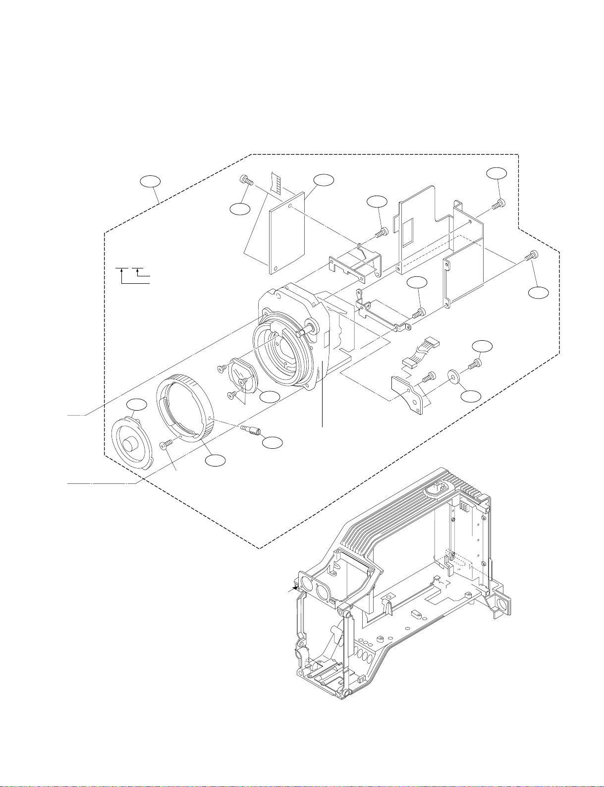
CCD Block
No. Part No. SP Description
*1:For DSR-500WS/500WSP
*1:Serial No. 12933- (UC), 32233- (J), 45216- (CE)
No. Part No. SP Description
308 3-672-221-02 s PACKING, CONTROL
309 3-672-250-01 s RING (M2.6), O
310 3-678-629-00 s LEVER, MOUNT
301 A-8322-435-A s CCD UNIT-R500WS(N)
[for DSR-570WS/500WS]
311 3-617-819-01 s CLAMP
312 3-686-269-02 s STOPPER, MOUNT
A-8322-436-A s CCD UNIT-R500WSP(P)
[for DSR-570WSP/500WSP]
302 1-758-131-11 o FILTER UNIT, OPTICAL
303 3-604-391-01 o COVER, SW(M)
305 A-8322-142-A o MOUNTED CIRCUIT BOARD, TG-204
313 3-710-054-01 s KNOB, FILTER
314 3-699-048-01 s CAP, MOUNT
315 3-701-506-01 s SET SCREW, DOUBLE POINT 3X4
316 3-184-550-31 s SCREW, +B2.6X4
317 3-686-191-01 o PLATE, FILTER-ID
306 3-708-987-01 s RING, BAYONET [for DSR-570WS/500WS]
3-708-651-01 s RING, BAYONET
[for DSR-570WSP/500WSP]
318 3-604-394-01 o FINGER, SHIELD(A)
319 3-729-076-11 s SCREW +B2X4 (STEEL)
307 3-617-801-03 o PANEL, FRONT [for DSR-500WS/500WSP]
3-613-310-21 o PANEL, FRONT [for DSR-570WS/570WSP]
PRECISION
P2.6 x 4
B3 x 14 TYPE-2
312
315
313
311
308
309
SW 3
B3 x 6
B3 x 6
LW 3
SW 3
303
B3 x 14 TYPE-2
*1
318
309
LW 3
307
1-8
DSR-570WS/570WSP/500WS/500WSP V2
CCD Block
316
305
301
314
PRECISION
P2 x 4
* How to read the CCD BLOCK NUMBER
Block number of CCD UNIT
CCD block type
(IF:DSR-570WS/500WS,
IG:DSR-570WSP/500WSP)
I H A xxxx
316
316
316
317
319
302
310
306
PRECISION
K2 x 5
PRECISION
K2 x 5
P2 x 4 (for DSR-570WS/500WS)
M2.3 x 6 PRECISION (for DSR-570WSP/500WSP)
316
BLOCK NO. LABEL
*1
DSR-570WS/570WSP/500WS/500WSP V2
1-9
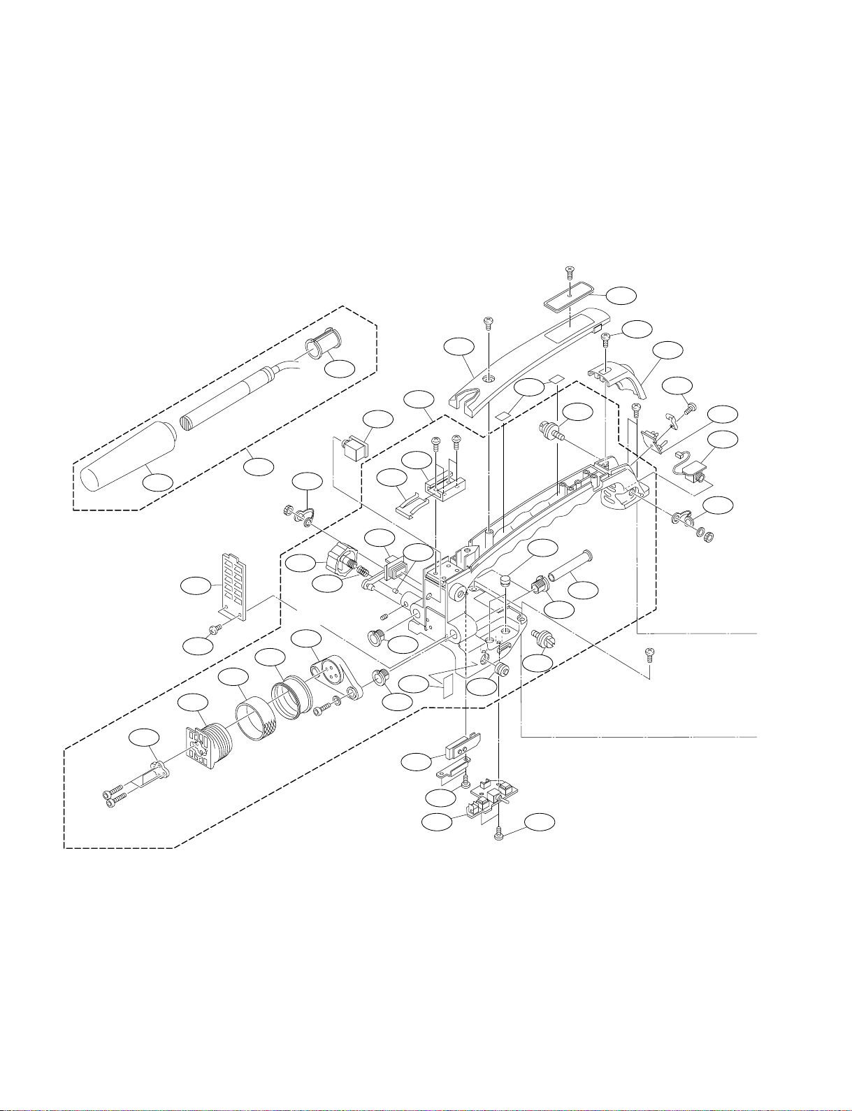
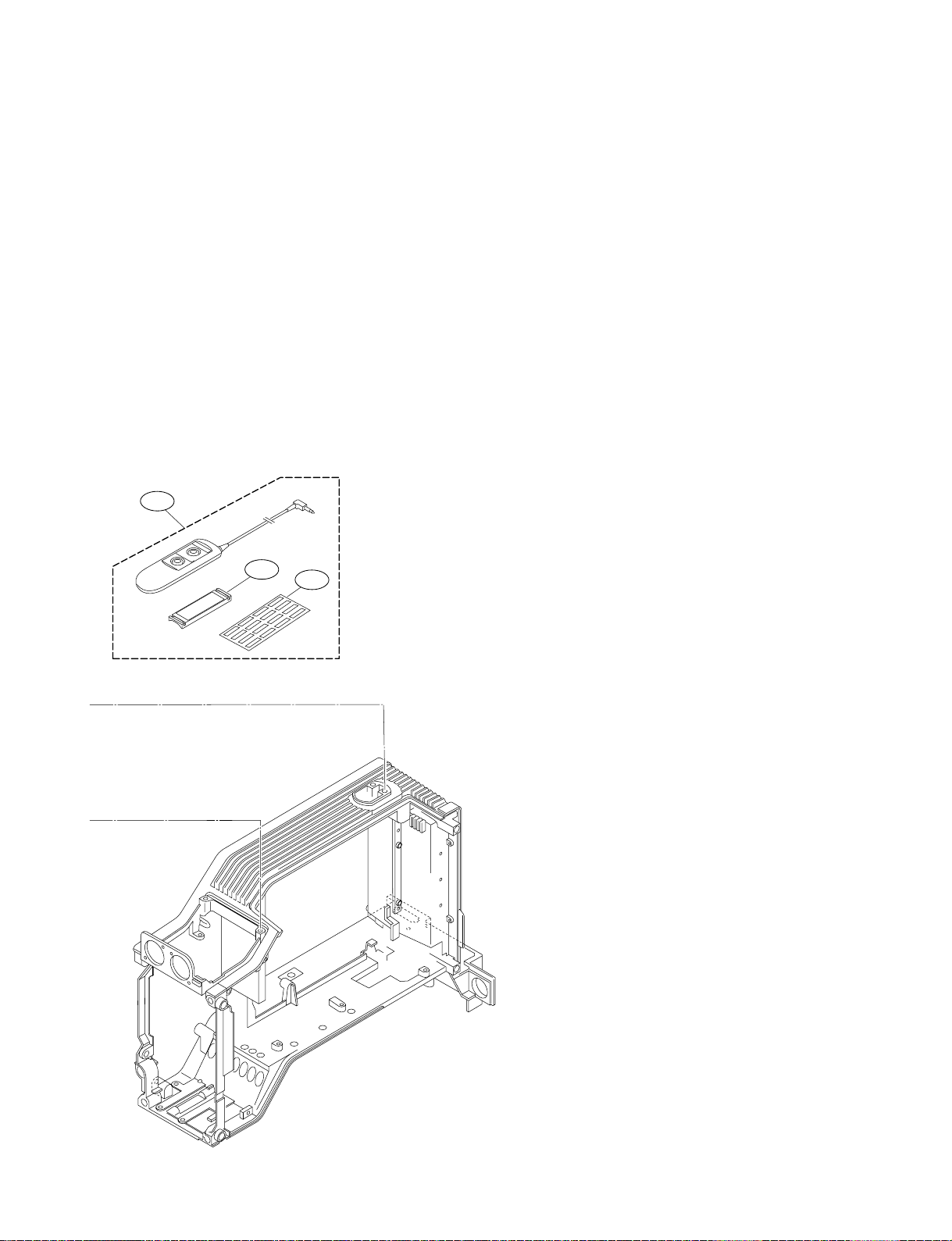
Handle Block
B3 x 8
435
425
428
413
424
437
429
408
421
410
431
415
419
SET SCREW
HEXAGON SOCKET
3x4 FLAT POINT
411
W4. SMALL
BOLT HEXAGON
SOCKET 4 x 12
409
416
426
422
422
427
418
401
417
P2 x 5
412
P2 x 5
420
B3 x 8
430
407
414
422
407
423
432
B3 x 8
B3 x 8
406
432
403
402
431
BOLT HEXAGON
SOCKET 3 x 25
BOLT HEXAGON
SOCKET 3 x 25
1-10
405
438
404 432
DSR-570WS/570WSP/500WS/500WSP V2
433
434
436
Handle Block
No. Part No. SP Description
*1,*2:For DSR-500WS/500WSP
*1:Serial No. 10001-12000(UC), 30001-32000(J), 40001-40850(CE)
*2:Serial No. 12001-(UC), 32001-(J), 40851-(CE)
401 A-8279-119-F o HANDLE ASSEMBLY, SUB(WS)
[for DSR-500WS/500WSP]
A-8278-801-G o HANDLE ASSY, SUB
[for DSR-570WS/570WSP]
402 1-673-950-11 o PRINTED CIRCUIT BOARD, CN-1867
403 A-8322-171-A o MOUNTED CIRCUIT BOARD, LE-221
404 A-8322-166-A o MOUNTED CIRCUIT BOARD, SW-18
405 1-673-956-11 o PRINTED CIRCUIT BOARD, CN-1874
406 X-3605-491-1 s COVER ASSEMBLY, HANDLE(WS)
[for DSR-500WS/500WSP]
X-3604-541-1 s COVER ASSY, HANDLE
[for DSR-570WS/570WSP]
407 X-3744-307-1 s SUSPENSION ASSEMBLY
408 1-542-296-23 o MICROPHONE
409 1-673-947-11 o PRINTED WIRING BOARD, CN-1866
410 3-179-882-01 o SPACER, MICROPHONE
411 3-612-600-12 s FIXING BASE, VF SHOE
[for DSR-500WS/500WSP]
3-612-600-01 s FIXING BASE, VF SHOE
[for DSR-570WS/570WSP]
412 3-612-624-12 s COVER, HANDLE(2)
[for DSR-500WS/500WSP]
3-612-624-04 s COVER, HANDLE(2)
[for DSR-570WS/570WSP]
413 3-612-629-02 s COVER, HANDLE(3)
414 3-612-632-02 s COVER, SW(H)
415 3-612-635-02 o FIXING KNOB, VF
for DSR-500WS-500WSP
416 3-612-664-11 s COVER, CN(ANTON)
[for DSR-500WS/500WSP]
3-612-664-01 s COVER, CN(ANTON)
[for DSR-570WS/570WSP]
417 3-612-665-01 o CUSHION(2)
418 *1 3-612-701-01 o LABEL, FILTER(A)
*2 3-604-403-01 o LABEL, FILTER(A)
419 3-612-822-01 s SPRING, COMPRESSION
420 3-676-244-03 s COVER, SWITCH
421 3-679-543-11 o RING(D), LOCK
422 3-679-684-01 o REST, ARM
423 3-686-197-01 o ARM, SLIDE
424 3-686-261-03 s SHOE3, SLIDE, VF
425 3-687-070-01 o WASHER, SHOE
426 3-688-754-11 s SPRING
427 3-688-755-11 s SHOE, ACCESSORY
428 3-624-426-01 s SCREEN, WIND
429 3-720-919-01 o RUBBER, LOCK RING
430 3-846-067-21 o SPACER (C)
431 3-849-405-00 s COVER, EARPHONE JACK
432 3-625-924-01 s ALOCK SCREW, +B2.6 NI
433 1-475-344-21 o REMOTE COMMANDER (RM-LG1)
[for DSR-500WS/500WSP]
434 9-980-573-01 o HOLDER ASSEMBLY
[for DSR-500WS/500WSP]
435 3-626-743-11 s COVER, HANDLE (4)
[for DSR-500WS/500WSP]
3-626-743-01 s COVER, HANDLE (4)
[for DSR-570WS/570WSP]
436 3-608-925-01 o LABEL, RM [VTR,MARK,CUE,NG]
[for DSR-500WS/500WSP]
437 3-370-476-11 s SCREW (NYLOCK +B2X5)
438 3-725-295-21 s SCREW, (+)(B3)
DSR-570WS/570WSP/500WS/500WSP V2
1-11
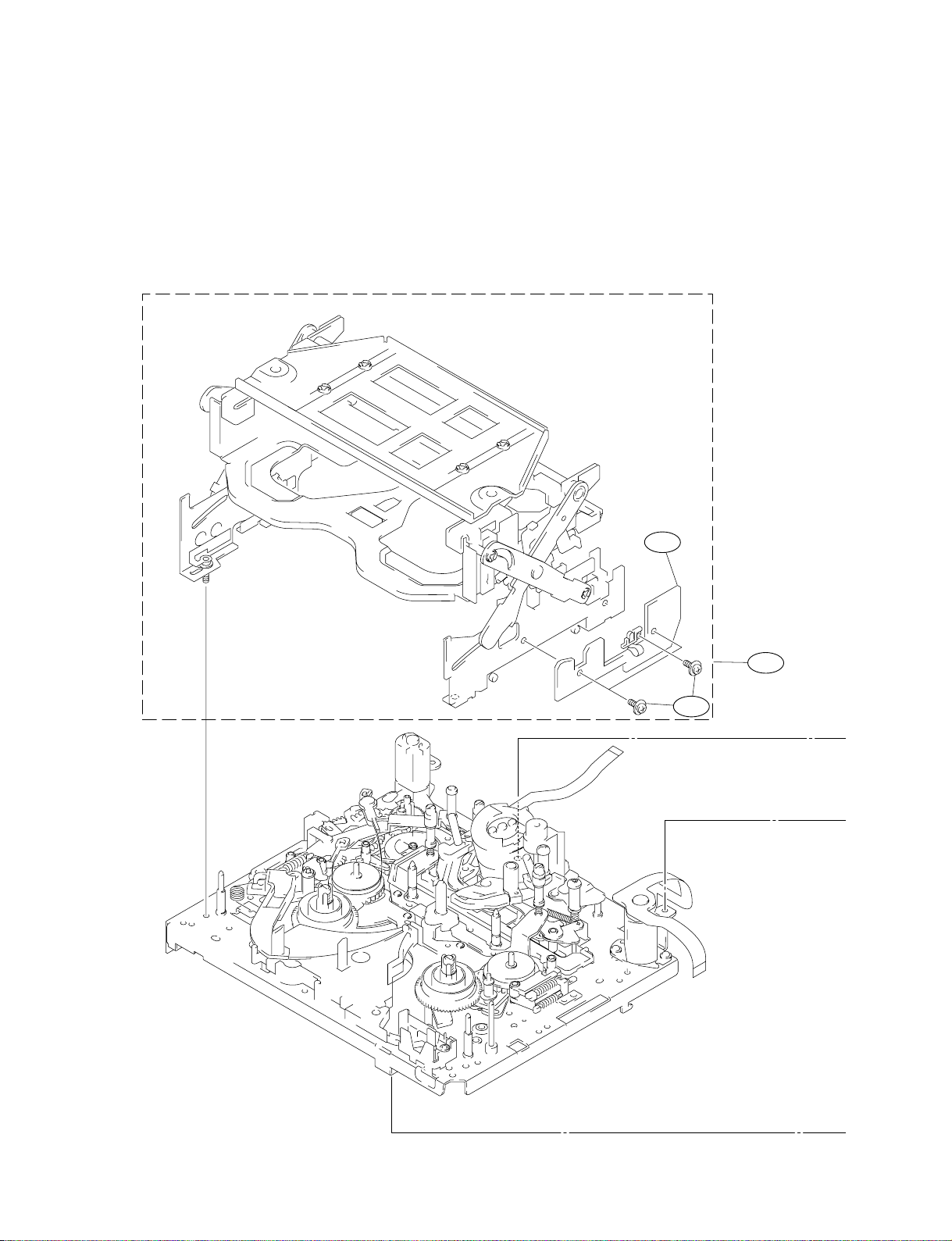
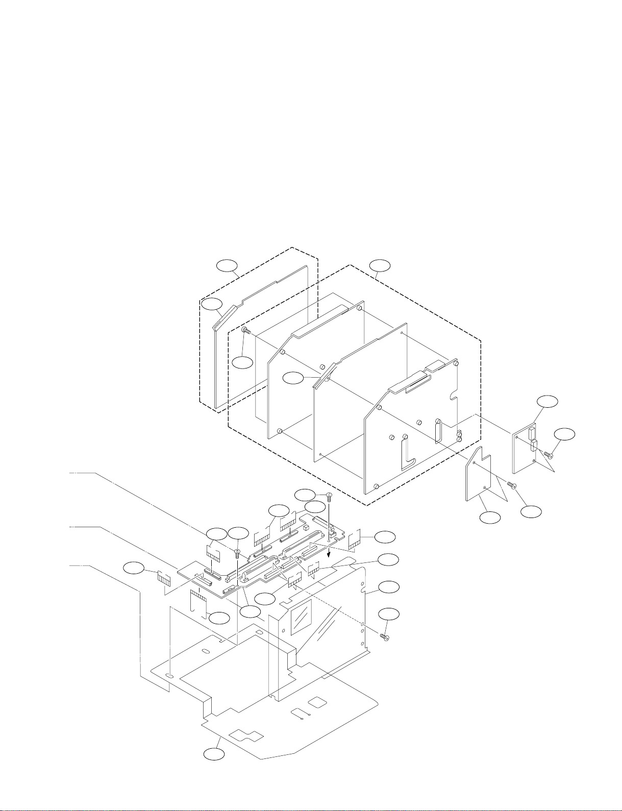
Cassette Compartment/Boards
No. Part No. SP Description
501 A-8277-832-C o MOUNTED CIRCUIT BOARD, CC-68
502 A-8277-852-A o MOUNTED CIRCUIT BOARD, RP-91
503 A-8277-853-A o MOUNTED CIRCUIT BOARD, HN-227
504 A-8322-140-B o MOUNTED CIRCUIT BOARD, SV-213
505 A-8315-150-L s CASSETTE COMPARTMENT ASSEMBLY
506 1-777-864-11 s CABLE, FLEXIBLE FLAT(20-CORE)
507 3-729-013-21 s SCREW(M1.4x2.5),WASHERHEAD(+P)
501
505
507
1-12
DSR-570WS/570WSP/500WS/500WSP V2
507
Cassette Compartment/Boards
502
506
507
507
503
507
507
507
DSR-570WS/570WSP/500WS/500WSP V2
507
504
507
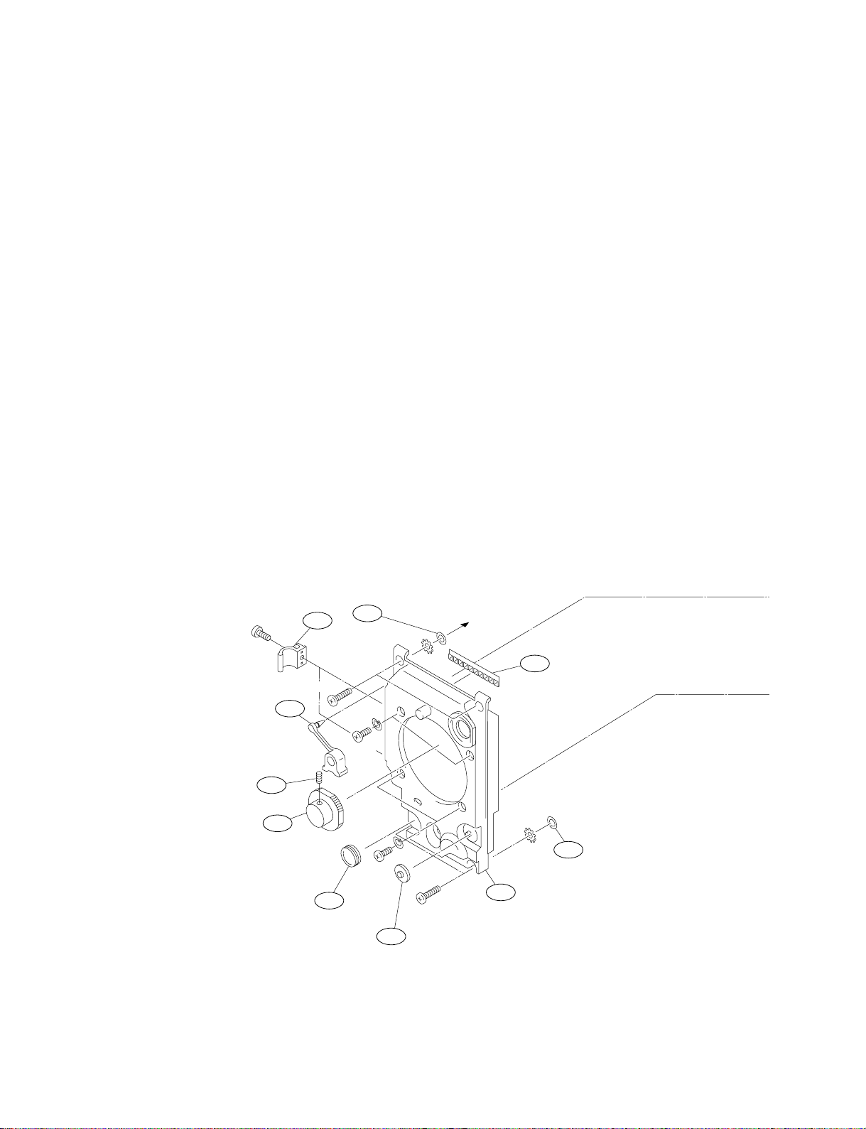
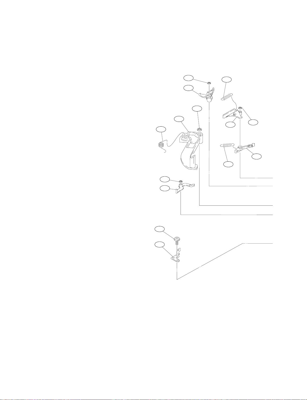
1-13

Guide
No. Part No. SP Description
601 A-8278-429-F s ARM ASSEMBLY,TR
602 X-3678-777-2 s BAND ASSEMBLY,TR
603 X-3678-788-4 s ARM ASSEMBLY,PINCH
604 X-3678-791-2 o ARM ASSEMBLY,TG7
605 X-3678-872-1 o BRACKET ASSEMBLY,SENSOR
606 X-3678-880-1 o TG#1/#8 BASE ASSEMBLY
607 X-3678-908-1 o WEIGHT ASSEMBLY,COUNTER
608 3-548-757-00 s SPRING, TENSION
609 3-604-702-02 s ROLLER,TG18
610 3-604-703-01 s LOWER FLANGE,TG1/8
611 3-604-704-01 s UPPER FLANGE,TG18
612 3-608-304-02 s SLEEVE,TG18
602
613 3-973-948-01 s UPPER FLANGE,TG3
614 3-966-099-11 s ROLLER,TG13
615 3-604-796-01 o SPRING(PINCH),TORSION
616 3-606-146-01 o SPRING(TG7),TORSION
617 3-604-832-01 s RETAINER, CAP
618 3-604-833-01 s CAP
619 3-604-861-02 o HOLDER,PRISM
620 3-604-953-01 s DETENT,TG7
601
625
625
623
617
624
618
621
635
623
605
626
621 3-607-208-01 s (TR)9,EXTENSION
622 3-605-319-01 o PRISM
619
623 3-701-436-11 s WASHER, 1.6 POLYETHYLENE
624 3-726-829-01 s WASHER, STOPPER
625 3-729-013-21 s SCREW(M1.4X2.5),WASHERHEAD(+P)
626 3-729-013-61 s SCREW(M1.4X4.5),WASHERHEAD(+P)
627 3-748-777-02 s TG7
622
628 3-940-891-01 s SPRING, COMPRESSION
629 3-964-614-01 s FLANGE, TG7 LOWER
630 3-966-100-11 s SLEEVE, TG13
631 3-623-839-01 s NUT, TG13
632 3-966-106-01 s FLANGE, TG3 LOWER
633 3-966-107-01 s SPRING, COMPRESSION
634 3-966-194-01 s FLANGE, TG7 UPPER
635 3-604-718-01 o ROLLER, TG2
1-14
DSR-570WS/570WSP/500WS/500WSP V2
631
613
614
630
632
633
611
609
612
610
633
625
606
616
624
634
627
629
628
604
608
Guide
603
625
607
DSR-570WS/570WSP/500WS/500WSP V2
615
620
1-15
Reel/Brake
No. Part No. SP Description
701 A-8278-432-C o ARM ASSEMBLY(T),HARD BRAKE
702 A-8278-433-A o ARM(S)ASSEMBLY,HARD BRAKE
703 A-8311-497-C o REEL(LARGE)ASSEMBLY
704 X-3678-869-1 s ARM(T)ASSEMBLY,SOFT BRAKE
705 X-3678-870-1 s SOFT BRAKE ASSEMBLY,TL
706 X-3678-881-3 o S PLATE ASSEMBLY,REEL
707 X-3678-882-3 o PLATE ASSEMBLY,T REEL
708 X-3608-225-1 o GEAR ASSEMBLY(T),SUB REEL
709 X-3608-226-1 o GEAR ASSEMBLY(S),SUB REEL
710 3-349-867-01 s SPRING, TENSION
724
727
720
718
726
713
726
711
730
717
726
702
728
722
711 3-446-154-99 s SPRING, TENSION
712 3-601-330-99 o HOOK(T),SPRING
713 3-603-966-02 o ARM,LOCK RELEASE
714 3-604-851-01 o ARM,SH RELEASE
715 3-604-855-01 o LEVER,TL,RELEASE
716 3-604-860-02 o RELEASE ARM,T BRAKE
717 3-605-314-01 s ARM(S),SOFT BRAKE
718 3-605-316-02 o ROCK ARM,REEL
719 3-605-317-01 o ROCK DRIVING ARM,REEL
720 3-605-318-01 o ARM,SS RELEASE
721 3-605-320-02 o STOPPER,REEL T
722 3-605-329-02 o HOOK(S),SPRING
723 3-605-332-01 o RETAINER,REEL PLATE
724 3-605-333-01 o PRESS SPRING,REEL LOCK
725 3-606-366-01 o LEVER,BRAKE,SOFT
726 3-669-465-01 s WASHER(1.5), STOPPER
727 3-726-829-01 s WASHER, STOPPER
728 3-729-013-21 s SCREW(M1.4X2.5),WASHERHEAD(+P)
729 3-908-649-01 s SPRING(OPEN)
730 3-913-922-01 s SPRING(T RELEASE), TENSION
731 4-930-450-01 s SPRING TENSION
732 3-331-685-01 s SPRING TENSION
1-16
DSR-570WS/570WSP/500WS/500WSP V2
 Loading...