

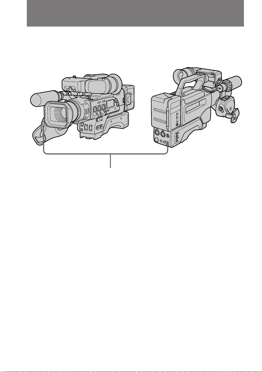
Page 1
3-862-712-11 (1)
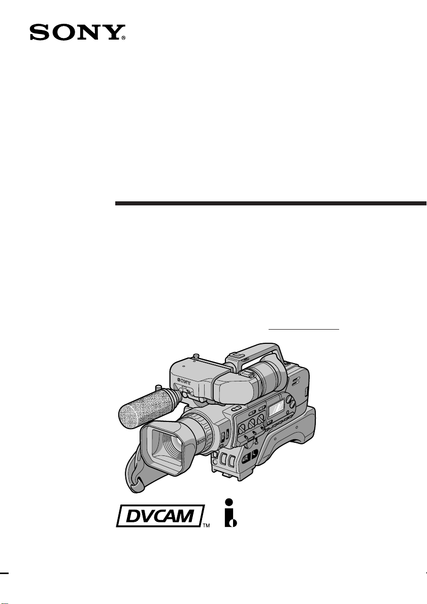
Digital Camcorder
Operating Instructions
Before operating the unit, please read this manual thoroughly,
and retain it for future reference.
Owner‘s Record
The model and serial numbers are located on the bottom. Record the
serial number in the space provided below. Refer to these numbers
whenever you call upon your Sony dealer regarding this product.
Model No. DSR-200A Serial No.
DSR-200A
©1998 by Sony Corporation
Page 2
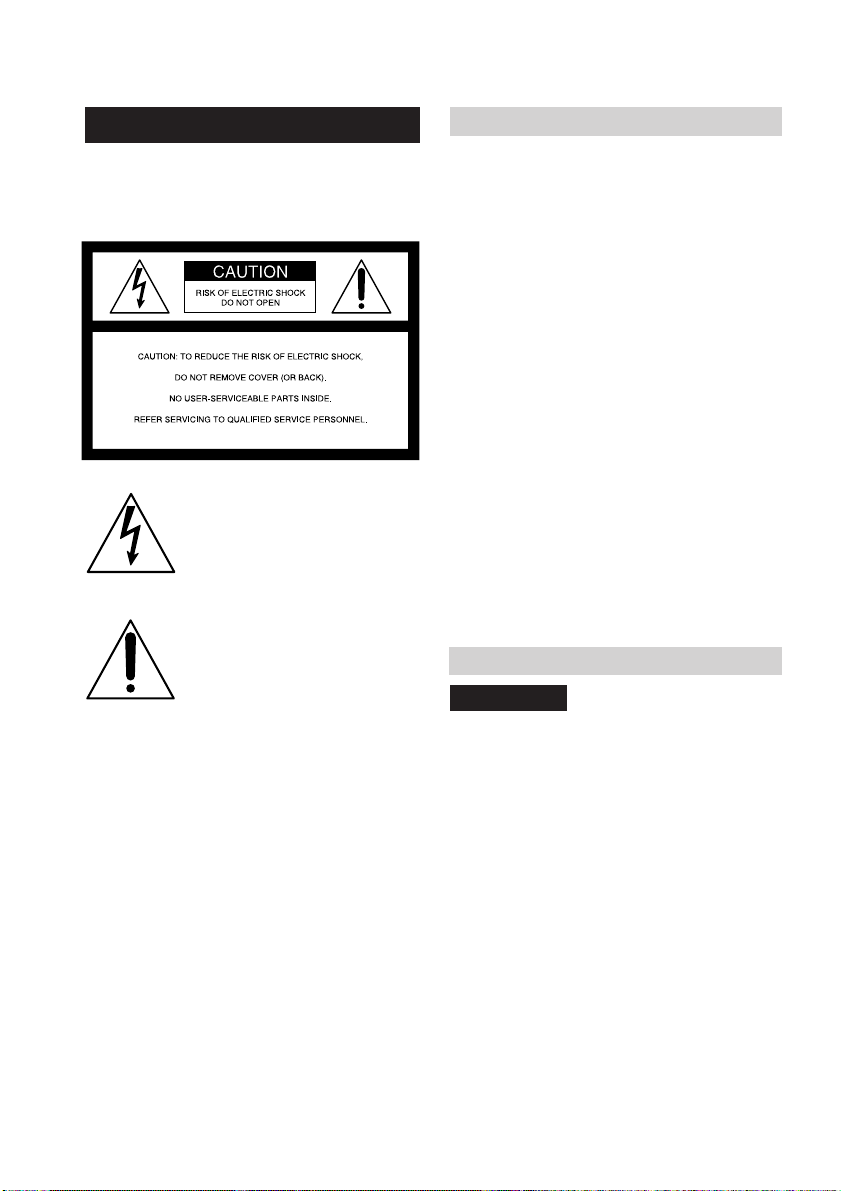
WARNING
To prevent fire or shock hazard, do
not expose the unit to rain or
moisture.
This symbol is intended to alert the
user to the presence of uninsulated
“dangerous voltage” within the
product’s enclosure that may be of
sufficient magnitude to constitute a
risk of electric shock to persons.
This symbol is intended to alert the
user to the presence of important
operating and maintenance
(servicing) instructions in the
literature accompanying the
appliance.
DISPOSAL OF LITHIUM ION BATTERY.
LITHIUM ION BATTERY.
DISPOSE OF PROPERLY.
You can return your unwanted lithium ion batteries
to your nearest Sony Service Center or Factory
Service Center.
Note: In some areas the disposal of lithium ion
batteries in household or business trash may
be prohibited.
For the Sony Service Center nearest you call
1-800-222-SONY (United States only)
For the Sony Factory Service Center nearest you call
416-499-SONY (Canada only)
For the customers in the U.S.A.
WARNING
This equipment has been tested and found to comply
with the limits for a Class B digital device, pursuant
to Part 15 of the FCC Rules. These limits are designed
to provide reasonable protection against harmful
interference in a residential installation. This
equipment generates, uses, and can radiate radio
frequency energy and, if not installed and used in
accordance with the instructions, may cause harmful
interference to radio communications. However,
there is no guarantee that interference will not occur
in a particular installation. If this equipment does
cause harmful interference to radio or television
reception, which can be determined by turning the
equipment off and on, the user is encouraged to try to
correct the interference by one or more of the
following measures:
— Reorient or relocate the receiving antenna.
— Increase the separation between the equipment
and receiver.
— Connect the equipment into an outlet on a circuit
different from that to which the receiver is
connected.
— Consult the dealer or an experienced radio/TV
technician for help.
You are cautioned that any changes or modifications
not expressly approved in this manual could void
your authority to operate this equipment.
For the customers in CANADA
CAUTION
TO PREVENT ELECTRIC SHOCK, DO NOT
USE THIS POLARIZED AC PLUG WITH AN
EXTENSION CORD, RECEPTACLE OR
OTHER OUTLET UNLESS THE BLADES
CAN BE FULLY INSERTED TO PREVENT
BLADE EXPOSURE.
Caution: Do not handle damaged or leaking lithium
ion battery.
2
Page 3

Table of contents
Before you begin
Using this manual ................................... 4
Checking supplied accessories.............. 5
Identifying the parts ............................... 6
Attaching optional accessories............ 17
Getting started
Attaching the viewfinder ..................... 20
Charging and installing the
battery pack .................................... 21
Inserting a cassette ................................ 24
Basic operations
Camera recording ................................. 26
Using the zoom feature ................. 30
Hints for better shooting ...................... 31
Checking the recorded picture............ 33
Connections for playback .................... 34
Playing back a tape ............................... 36
Advanced operations
Using alternative power sources ........ 38
Changing the mode settings................ 40
– for camera recording –
Fade-in and fade-out ............................ 43
Overlapping two pictures.................... 44
Using the wide mode function............ 45
Photo recording..................................... 46
Interval recording ................................. 47
Cut recording......................................... 48
– for manual adjustment –
Selecting automatic or manual mode
........................................................... 49
Focusing manually................................ 51
Adjusting the aperture ......................... 54
Adjusting the shutter speed ................ 55
Adjusting the gain ................................ 58
Adjusting the white balance................ 60
Using the ND filter ............................... 63
Using the zebra pattern........................ 64
Adjusting the recording sound ........... 65
Releasing the STEADY SHOT function
........................................................... 68
Making a custom preset ....................... 69
– for editing/playback –
Searching the recorded picture ........... 71
Displaying recording data ................... 73
Editing onto another tape .................... 74
Audio dubbing ...................................... 76
Additional information
Changing the lithium battery in the
digital camcorder ........................... 78
Resetting the date and time ................. 80
Compatibility of DVCAM and DV
formats ............................................. 81
Notes on video cassettes ...................... 83
Tips for using the battery pack ........... 84
Maintenance information and
precautions ...................................... 86
Using your digital camcorder abroad
........................................................... 89
Trouble check ........................................ 90
Specifications ......................................... 94
Warning indicators ............................... 95
Index ........................................ Back cover
3
Page 4
Before you begin
Using this manual
As you read through this manual, buttons and settings on the digital camcorder are
shown in capital letters.
e.g. Set the POWER switch to ON.
As indicated with ≥ in the illustrations, you can hear the beep sound to confirm your
operation.
Note on TV color systems
TV color systems differ from country to country. To view your recordings on a TV, you
need an NTSC system-based TV.
Precaution on copyright
Television programs, films, video tapes, and other materials may be copyrighted.
Unauthorized recording of such materials may be contrary to the provision of the
copyright laws.
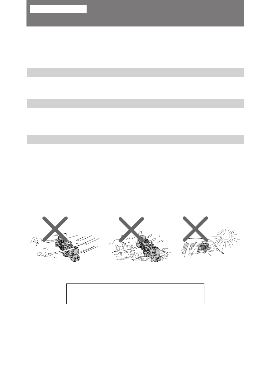
Precautions on digital camcorder care
• Do not let sand get into the digital camcorder. When you use the digital
camcorder on a sandy beach or in a dusty place, protect it from the sand or dust.
Sand or dust may cause the unit to malfunction, and sometimes this
malfunction cannot be repaired [a].
• Do not let the digital camcorder get wet. Keep the digital camcorder away from
rain and sea water. Letting the digital camcorder get wet may cause the unit to
malfunction, and sometimes this malfunction cannot be repaired [b].
• Never leave the digital camcorder exposed to temperatures above 140°F (60°C),
such as in a car parked in the sun or under direct sunlight [c].
[b] [c][a]
Contents of the recording cannot be compensated if
recording or playback is not made due to a malfunction of
the digital camcorder, video tape, etc.
4
Page 5
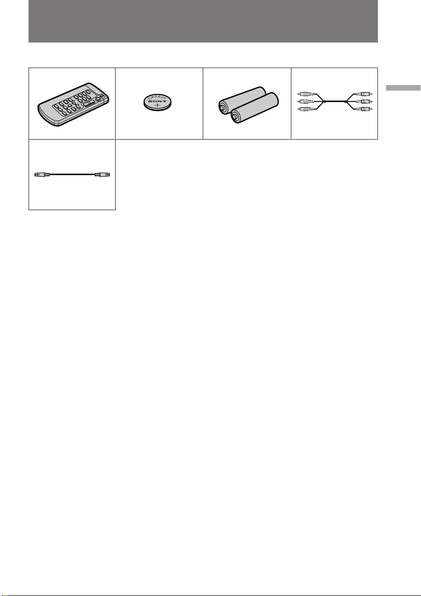
Checking supplied accessories
Check that the following accessories are supplied with your digital camcorder.
123 4
5
Before you begin
1 Wireless Remote Commander (1) (p.11)
2 CR2025 Lithium Battery (1) (p. 78)
The lithium battery is already installed
in your digital camcorder.
3 Size AA (R6) battery for Remote
Commander (2) (p. 12)
4 A/V connecting cable (1) (p. 34)
5 S video cable (1) (p. 34)
5
Page 6
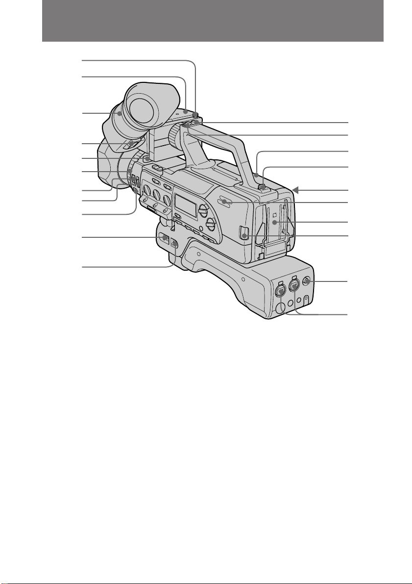
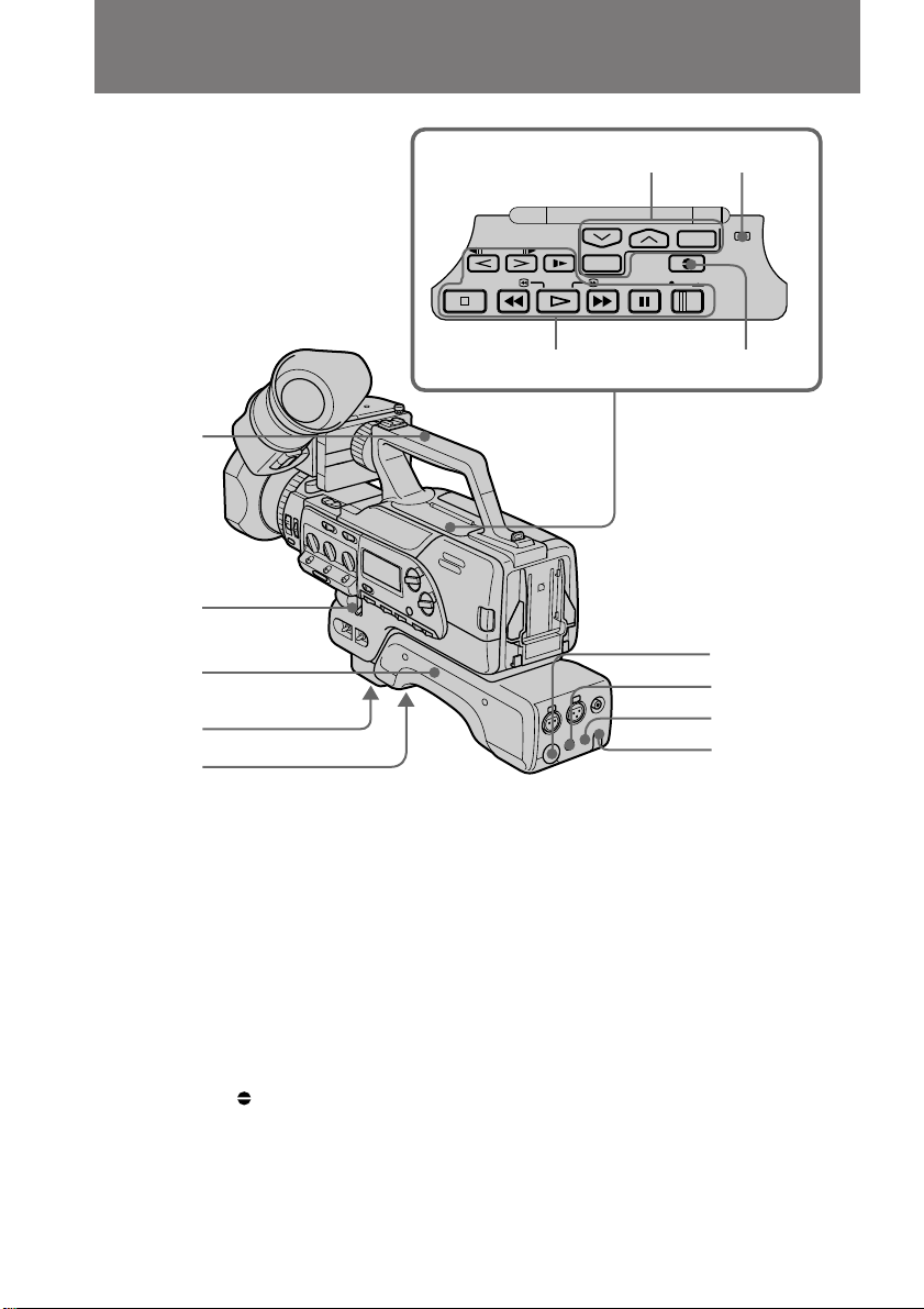
Identifying the parts
1
2
3
4
5
6
7
8
9
0
!¡
1 Stopper (p. 20)
Lift up and hold to remove the
viewfinder.
2 Viewfinder (p. 20, 27, 87)
3 Viewfinder adjustment ring (p. 27)
4 PUSH button (p. 87)
Press and hold to raise the eyecup.
5 Viewfinder release lever (p. 32)
Push forward to move the position of
the viewfinder front and back.
6 Focus ring (p. 52)
7 FOCUS switch (p. 52)
Set to select auto or manual focus.
8 ND FILTER switch (p. 63)
9 PUSH AUTO button (p. 52)
Push to use automatic focus
momentarily.
!º POWER switch (p. 26)
6
!™
!£
!¢
!∞
!§
!¶
!•
!ª
@º
@¡
!¡ CAMCORDER/VTR switch (p. 26)
!™ Accessory shoe (p. 46)
!£ Hook for shoulder strap (p. 16)
!¢ Cassette compartment and cassette
compartment cover (p. 24)
!∞ Hook for shoulder strap (p. 16)
!§ EJECT 6 button (p. 25)
Press to eject the cassette.
!¶ Speaker (p. 28)
!• Battery mounting surface (p. 23)
!ª BATT lever (p. 23)
Press and hold to release the batteries.
@º VIDEO OUT jack (for BNC type plug)
(p. 35)
@¡ AUDIO IN jacks (p. 65)
Input external audio/microphone
signals.
Page 7
Identifying the parts
@™
@£
@¢
@∞
@§
@¶
@•
@ª
#º
@™ Microphone holder attaching point
(p. 18)
@£ TALLY lamp (p. 27)
Lights while recording and when the
battery becomes low.
@¢ CONTR knob (p. 27)
Turn to adjust the viewfinder’s contrast.
@∞ TALLY switch (p. 27)
Set to select TALLY lamp ON/OFF.
@§ Front Remote Commander sensor
(p. 14)
@¶ Grip (p. 31)
@• Grip strap (p. 31)
@ª Lens hood
You can attach a wide teleconversion
lens (not supplied) by removing the lens
hood.
#¡
#™
#£
#¢
#∞
#§
#º Lens hood cap (p. 26)
#¡ BRIGHT knob (p. 27)
Turn to adjust the viewfinder’s
brightness.
#™ EDITSEARCH button (p. 33)
#£ Front START/STOP button (p. 31)
#¢ FADER/OVERLAP button (p. 43, 44)
#∞ WHITE BALANCE ∑ (one-push white
balance) button (p. 60)
#§ CP CHECK button (p. 70)
Press to check the custom preset
settings.
Before you begin
7
Page 8
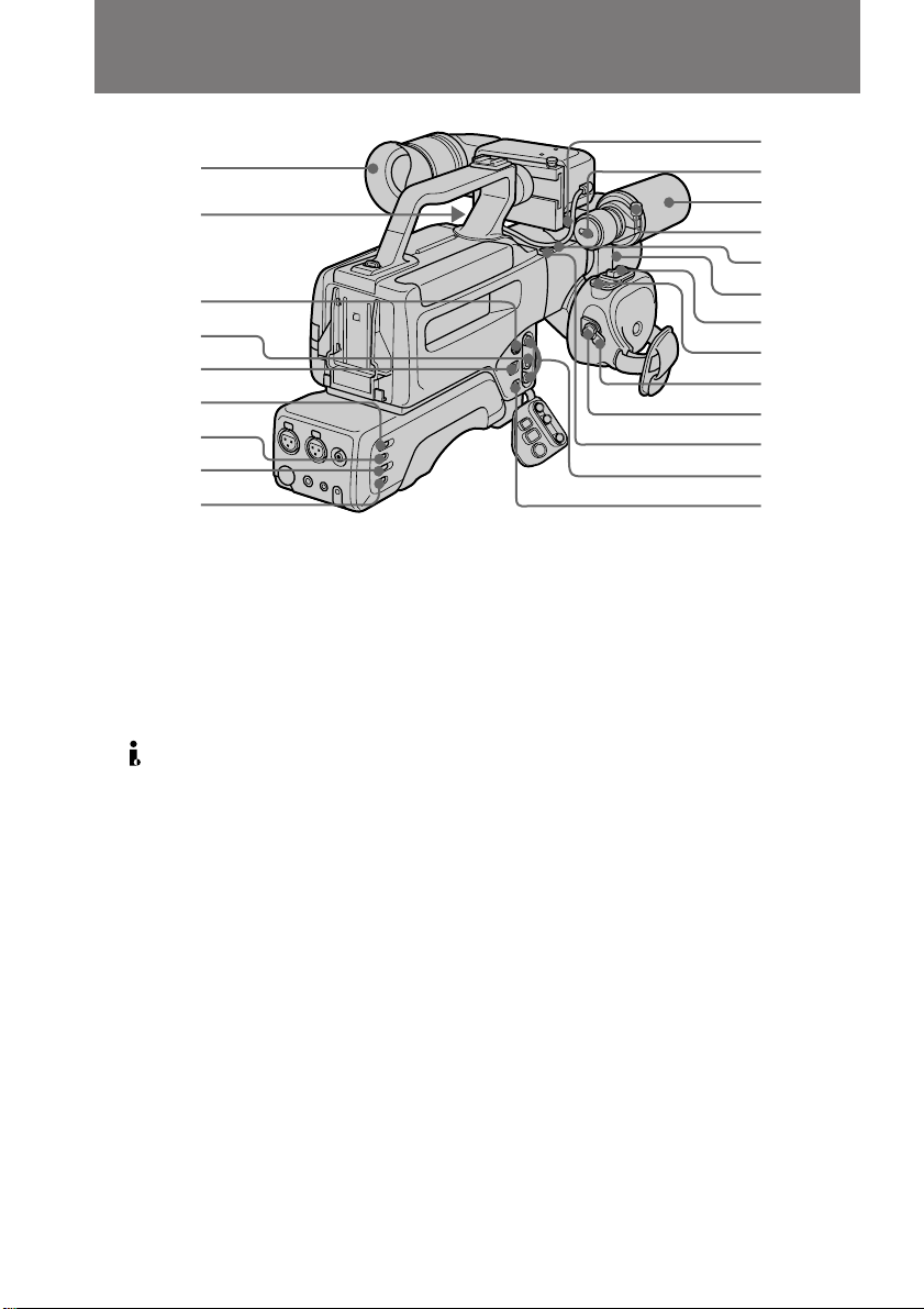
Identifying the parts
#¶
#•
#ª
$º
$¡
$™
$£
$¢
$∞
$§
$¶
$•
$ª
%º
%¡
%™
%£
%¢
%∞
%§
%¶
%•
#¶ Eyecup
#• VIEW FINDER jack (p. 20)
#ª S VIDEO OUT jack (p. 34)
$º RFU DC OUT jack (p. 35)
$¡ DV IN/OUT jack (p. 74)
Connect DV products using the
connecting DV cable.
This “i.LINK” mark is a trademark of
Sony Corporation and indicates that this
product is in agreement with IEEE 13941995 specifications and their revisions.
The DV IN/OUT jack is i.LINK
compatible.
$™ CH-1 LINE/MIC switch (p. 65)
Set to change the audio source using a
CH-1 input.
$£ CH-1 ATT switch (p. 67)
Set ON to attenuate the CH-1 input
microphone level.
$¢ CH-2 LINE/MIC switch (p. 65)
Set to change the audio source using
CH-2 input.
$∞ CH-2 ATT switch (p. 67)
Set ON to attenuate the CH-2 input
microphone level.
8
$§ MIC (PLUG IN POWER) jack (p. 28)
Connect an external mini jack type
microphone (not supplied). This jack
also accepts a “plug-in-power”
microphone. When using this jack, set
LINE/MIC to MIC FRONT.
$¶ DIRECTION SELECT switch (p. 29)
Set to change the directionality of the
built-in microphone.
$• Built-in microphone (p. 65)
$ª Microphone wind screen screw
Loosen to remove wind screen.
%º MIC switch (p. 67)
Set ATT to attenuate the built-in
microphone and external microphone
connected to MIC (PLUG IN POWER)
level.
%¡ Lens hood screw
%™ Power zoom button (p. 30)
%£ PHOTO button (p. 46)
Press to shoot in photo mode.
%¢ STANDBY (LOCK/STANDBY/PHOTO
STANDBY) switch (p. 26)
%∞ START/STOP button (p. 26)
%§ BUILT-IN MIC switch (p. 67)
If recording when there is a loud wind
using the built-in microphone, set to
WIND.
%¶ AUDIO OUT/VIDEO OUT jacks (p. 34)
%• DC IN jack (p. 38)
Page 9
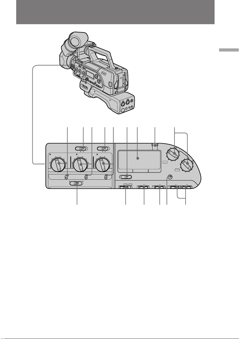
Identifying the parts
%ª ^º ^™ ^¢ ^∞ ^§ ^¶^¡ ^£
Before you begin
%ª SHUTTER SPEED dial and AUTO/
MANUAL switch (p. 55)
^º VF DISPLAY switch (p. 28)
Set to display (ON) or erase (OFF) the
indicators in the viewfinder.
^¡ GAIN dial and AGC/MANUAL switch
(p. 58)
^™ STEADY SHOT switch (p. 68)
^£ WHT BAL (white balance) dial and
ATW/MANUAL switch (p. 60, 61)
^¢ DISPLAY LIGHT switch (for display
window)
Use to set the display back light switch
ON/OFF.
^∞ Display window (p. 16)
^§ PEAK indicators (L and R) (p. 66)
&º&¡&™&£ ^ª ^•
^¶ REC LEVEL dials (p. 66)
^• REC LEVEL switches (p. 66)
^ª TC RESET button
Set time code to 0:00:00:00 when you
want to reset the time code while
shooting.
&º AUDIO MODE switch (p. 29)
Set to select Fs 32k (12 bit) or Fs 48k
(16 bit) audio recording mode.
&¡ SPEAKER switch (p. 28)
&™ AUDIO MONITOR switch (p. 66)
&£ AUTO LOCK switch (p. 26)
Set to turn automatic settings for
aperture, shutter speed, gain, and white
balance ON/OFF.
9
Page 10
Identifying the parts
*¡*º
*£ *™
&¢
&∞
&§
&¶
&•
&¢ Carrying handle
&∞ IRIS dial and AUTO/MANUAL switch
(p. 54)
&§ Shoulder pad
&¶ Tripod receptacle (p. 17)
&• Lithium battery cover (p. 79)
&ª Cover for menu and video controls
*º Menu buttons (p. 40)
*¡ TC switch (p. 28)
Set to select the drop frame or non-drop
frame for time code recording.
*™ AUDIO DUB
*£ Video controls (p. 36)
π STOP button (stop)
0 REW button (rewind)
· PLAY button (playback)
) FF button (fast forward)
button (p. 77)
&ª
*¢
*∞
*§
*¶
P PAUSE button (pause)
r REC switch (recording)
& SLOW button (slow speed playback)
'/7 FRAME button (direction
select/frame-by-frame)
*¢ MONITOR LEVEL dial (p. 28)
Turn to adjust the volume level of the
headphones and built-in speaker.
*∞ 2 (headphones) jack (p. 28)
*§ l LANC jack
l stands for Local Application Control
Bus System. The l control jack is used
for controlling the tape transport of
video equipment and peripherals
connected to it. This jack has the same
function as the jack indicated as
CONTROL L or REMOTE.
*¶ Tally lamp/Rear Remote Commander
sensor (p. 27, 14)
10
Page 11
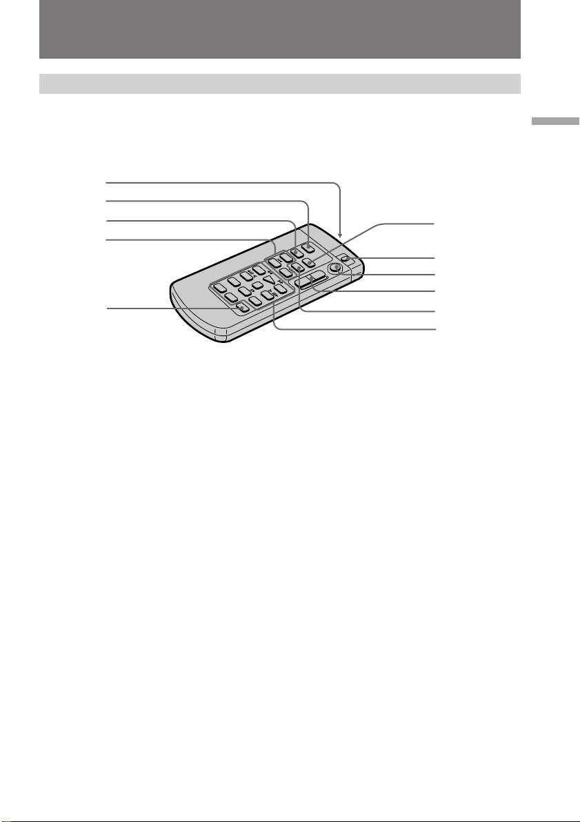
Identifying the parts
Remote Commander
The buttons that have the same name on the Remote Commander as on the digital
camcorder function identically.
1
2
3
4
5
Before you begin
6
7
8
9
!º
!¡
1 Transmitter
Point toward the remote sensor to
control the digital camcorder after
turning on the digital camcorder.
2 PHOTO button (p.46)
3 DISPLAY button (p. 36)
4 SEARCH MODE/=/+ buttons
(p. 71)
Press SEARCH MODE to select date
search or photo search.
5 AUDIO DUB button (p. 77)
6 ZERO SET MEMORY button
This button does not function.
7 VTR4/ID/VTR2 switch (p. 13)
Select VTR4 or ID, the same setting as
COMMANDER in the menu system.
The VTR2 position does not function on
this digital camcorder.
8 START/STOP button
9 Zoom button
The zooming speed is unchangeable by
the Remote Commander.
!º DATA CODE button (p. 73)
!¡ Video control buttons
11
Page 12
Identifying the parts
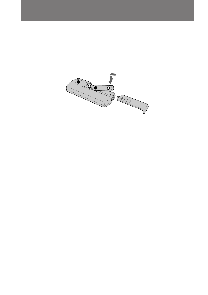
To prepare the Remote Commander
To use the Remote Commander, you must insert two size AA (R6) batteries. Use the
supplied size AA (R6) batteries.
(1) Remove the battery cover from the Remote Commander.
(2) Insert both of the size AA (R6) batteries with correct polarity.
(3) Put the battery cover back onto the Remote Commander.
Note on battery life
The batteries for the Remote Commander last about 6 months under normal operation.
When the batteries become weak or dead, the Remote Commander does not work.
To avoid damage from possible battery leakage
Remove the batteries when you will not use the Remote Commander for a long time.
12
To use the Remote Commander
Make sure that the COMMANDER is set to VTR4/ID in the menu system on the digital
camcorder.
Page 13
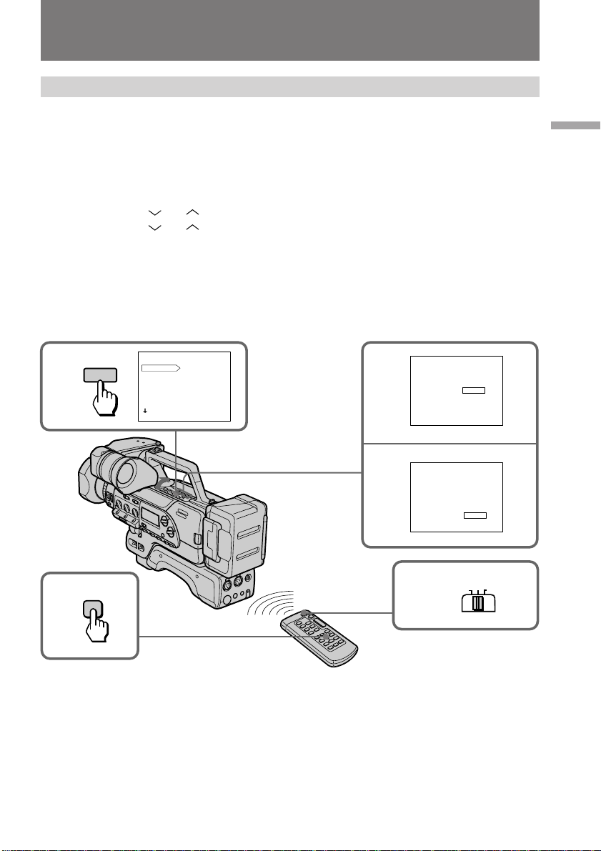
Identifying the parts
About the ID of the Remote Commander
You can avoid having the digital camcorder accidentally respond to signals from other
remote commanders by setting the VTR4/ID/VTR2 switch to ID. Use the supplied
Remote Commander when you set the switch to ID. When you use the Remote
Commander for the first time, register the ID following the procedure below. Once you
have registered the ID, you do not need to do so again.
(1) Install a power source, open the cover, then press MENU to display the menu
in the viewfinder.
(2) Press
(3) Press
(4) Set VTR4/ID/VTR2 on the Remote Commander to ID.
(5) Point the Remote Commander at the Remote Commander sensor on the digital
camcorder and press π on the Remote Commander.
After the beep sound, the ID of the Remote Commander is registered, and the
COMMANDER is set to ID in the menu system.
(6) Press MENU to erase the menu display.
or to select COMMANDER, then press EXECUTE.
or to select ID SET.
Before you begin
1
5
MENU
STOP
MENU
DIGITAL F ZOOM/WIDE
D ZOOM
16:9WIDE
ZEBRA
TC IND
DATE/TIME
COMMANDER
[ MENU ] : END
2
3
MENU
COMMANDER VTR4
OFF
ID
ID SET
[ MENU ] : END
MENU
COMMANDER VTR4
OFF
ID
ID SET
COMMANDER [ STOP ] : ID SET
4
VTR 4
ID
VTR 2
13
Page 14
Identifying the parts
Remote control direction
Aim the Remote Commander at either of the two remote commander sensors.
The range of the Remote Commander is about 16 feet (about 5 m) indoors. Use the
Remote Commander as close to flat as possible, otherwise it may not work.
Remote Commander Sensors
Notes on the Remote Commander
•Keep the Remote Commander sensor away from strong light sources such as direct
sunlight or illumination. Otherwise, the remote control may not be effective.
•Be sure that there is no obstacle between the Remote Commander sensor on the digital
camcorder and the Remote Commander.
•This digital camcorder works in commander mode VTR 4 or ID. The commander
modes (VTR 4 and ID) are used to distinguish this digital camcorder from other Sony
VCRs. If you use another Sony VCR at commander mode ID, we recommend that you
change the commander mode or cover the Remote Commander sensor of the VCR
with black paper.
•You do not need to store the ID again, after having done so once. Set COMMANDER
to ID in the menu system, and set the VTR4/ID/VTR2 switch on the Remote
Commander to ID.
•The stored ID is not erased even if you replace the lithium battery.
14
Page 15
Identifying the parts
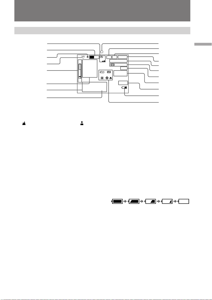
In the viewfinder
1
2
3
4
5
6
7
T
16:9WIDE
W
JUL. 4 1998
10:13:02 AM
1 0 0 0
F 2 . 8
0 dB
FADER
8
1 Manual focusing indicator (p. 53)
appears when focusing far,
appears when focusing close.
2 ND filter indicator (p. 63)
3 White balance indicator (p. 60)
4 Steady shot indicator (p. 68)
5 Zoom indicator (p. 30, 52)
6 Manual setting data/wide mode/
fader or overlap/AGC LMT indicators
(p. 54, 55, 58, 45, 43, 44)
If not set, the indicator disappears, and
all indicators below rise 1 row.
7 Data code indicators (p. 73)/Date and
Time indicators (p. 41)
8 Lithium battery indicator (p. 78)
9 Recording/battery indicator (p. 26)
0 Custom preset indicator (p. 69)
CP DV
ONND
I
STBY
0 :13 : 46: 05
170 m i n
48k
PHOTO
DV IN
!¡ DV indicator (p. 37)
During DV-formatted cassette playback,
this indicator appears.
!™ Video control mode (p. 26)
!£ Time code
!¢ Remaining tape indicator
!∞ Audio mode indicator (p. 29)
!§ INTERVAL/FRAME REC/PHOTO/
C MEMORY/date search/Photo search
indicator (p. 47, 48, 46, 25, 71)
!¶ DV IN indicator (p. 74)
!• Remaining battery indicator (p. 84)
!ª Warning indicators (p. 95)
9
0
!¡
!™
!£
!¢
!∞
!§
!¶
!•
!ª
Before you begin
15
Page 16
Identifying the parts
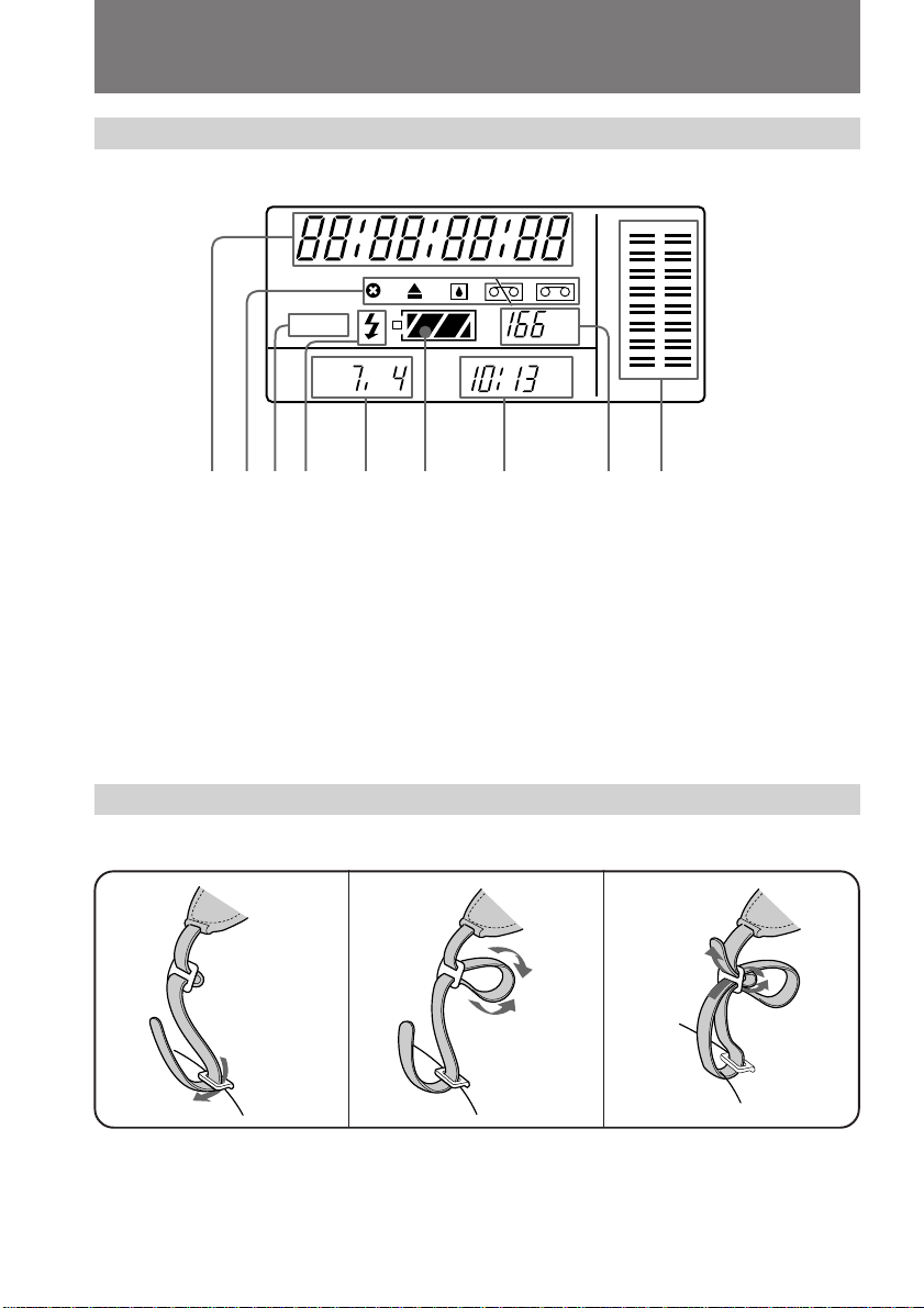
In the display window
HMSF
DVCAM
F
143562789
1 Time code
2 Warning indicators (p. 95)
3 DVCAM indicator
Lights up when using a DVCAMformatted cassette.
4 Flash indicator
Attaching the shoulder strap
Attach the shoulder strap (not supplied) to the hooks for the shoulder strap.
1
2
min
AM
5 Date/aperture indicator (p. 54)
6 Remaining battery indicator (p. 84)
7 Time indicator
8 Remaining tape indicators
9 Audio level indicators (p. 66)
3
16
Page 17
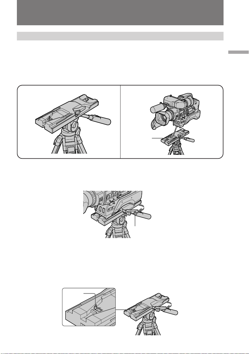
Attaching optional accessories
Attaching digital camcorder to the tripod adaptor
Use the VCT-U14 tripod adaptor (not supplied). Once the tripod adaptor has been
attached to the tripod stand, then you may attach the digital camcorder.
(1) Attach the tripod adaptor to the tripod.
(2) Attach the digital camcorder to the tripod stand’s grooved surface [a], and
slide it forward until you hear a click.
Select a balanced and secure position for the tripod stand.
Before you begin
1
To remove the digital camcorder from the tripod
Press the red button on the release lever [b], and while holding, move the lever in the
direction of the arrow to release the lock.
Note on tripod attachment pin
If the tripod attachment pin [c] does not return after removing the digital camcorder,
press the red button on the release lever, and while holding, move the lever in the
direction of the arrow and the pin returns to its original position. If the pin is not set in
its original position you will not be able to reattach the digital camcorder.
2
[a]
[b]
[c]
17
Page 18
Attaching optional accessories
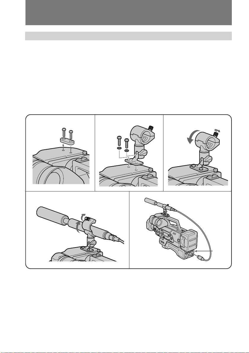
Attaching the external microphone with XLR connector
When using the ECM-672 external microphone (not supplied), attach the CAC-12
microphone holder (not supplied) to the digital camcorder.
(1) Remove the screws from the top of the viewfinder.
Remove the spacer from the screws. They are unnecessary when attaching the
microphone holder.
(2) Attach the microphone holder with the supplied washers and the screws
removed in step (1).
(3) Loosen the microphone holder screw and open the cover.
(4) Place the microphone into the holder, close the cover, and tighten the screw.
(5) Connect the microphone to the AUDIO IN jacks of the digital camcorder, then
set LINE/MIC to MIC REAR.
1
4
2
3
5
LINE/
MIC
AUDIO IN
18
Page 19
[d]
CHECK
Attaching optional accessories
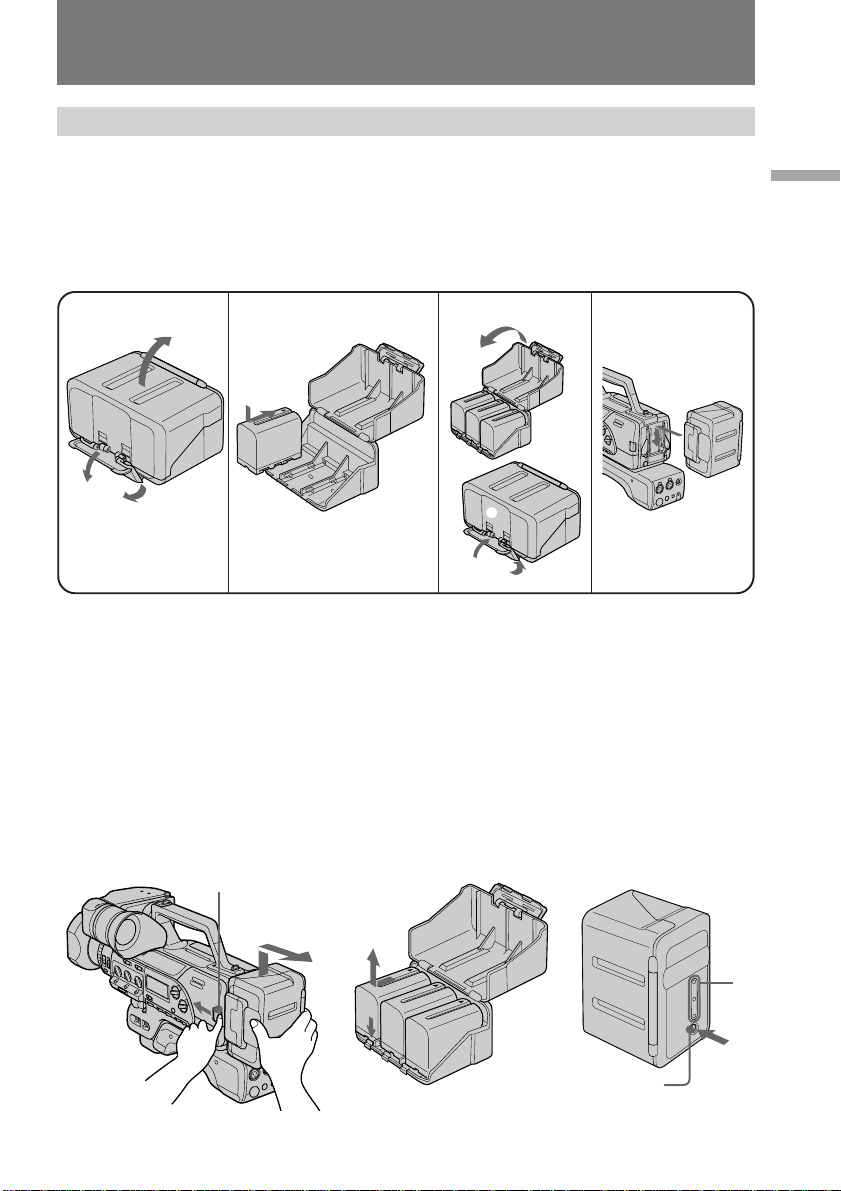
Attaching the battery adaptor
The NPA-10000 battery adaptor (not supplied), can hold up to 3 battery packs NP-F950
or NP-F750 (not supplied). Attach the adaptor to the digital camcorder.
(1) Release the lock and open the cover.
(2) Insert the battery packs in the direction of the z mark on the battery packs.
(3) Close the cover, then lock.
(4) Attach the battery adaptor to the digital camcorder by sliding until it clicks.
Before you begin
1
1
3
2
234
1
3
2
To remove the battery adaptor [a]
While pressing BATT, lift the battery adaptor out in the direction of the arrow.
To remove the battery pack [b]
Open the cover, press and hold the release lever, and slide the battery pack out in the
direction of the arrow.
Checking the remaining battery indicator [c]
Press CHECK on the battery adaptor.
If there is still power left in the batteries, the lamp [d] lights.
[b]
BATT
[c][a]
19
Page 20
VIEW
FINDER
Getting started
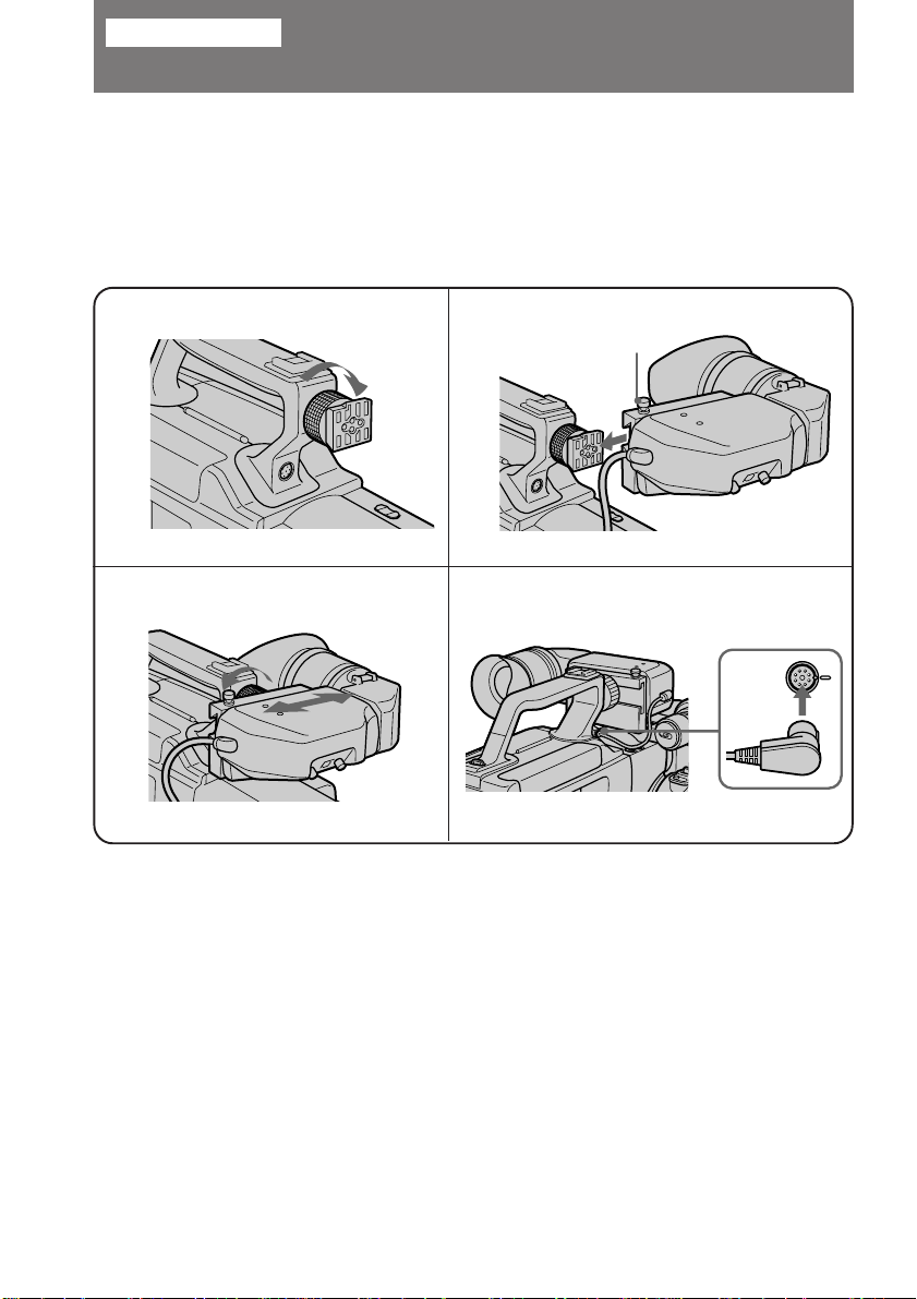
Attaching the viewfinder
Before using the digital camcorder, attach the viewfinder.
(1) Loosen the viewfinder release ring.
(2) Slide the viewfinder onto the attaching plate.
(3) Adjust the position of the viewfinder, then tighten the viewfinder release ring.
(4) Attach the 8 pin connector to the VIEW FINDER jack on the digital camcorder.
Match ridge on 8 pin connector to the ridge on the jack.
1
3
Note on the VIEW FINDER jack
This VIEW FINDER jack is specially designed for this digital camcorder. Do not connect
anything else to this VIEW FINDER jack.
2
4
[a]
20
To remove the viewfinder
Loosen viewfinder release ring. Then pull stopper [a] up, and while holding, slide
viewfinder off the attaching plate.
Page 21
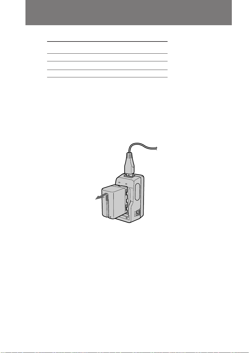
Charging and installing the battery pack
Before using your digital camcorder, you first need to charge and install the battery
pack (not supplied). To charge the battery pack, use the AC-V615 AC power adaptor
(not supplied).
This digital camcorder does not interface with “InfoLITHIUM” batteries. The remaining
time (minutes) indication does not appear when using “InfoLITHIUM” batteries.
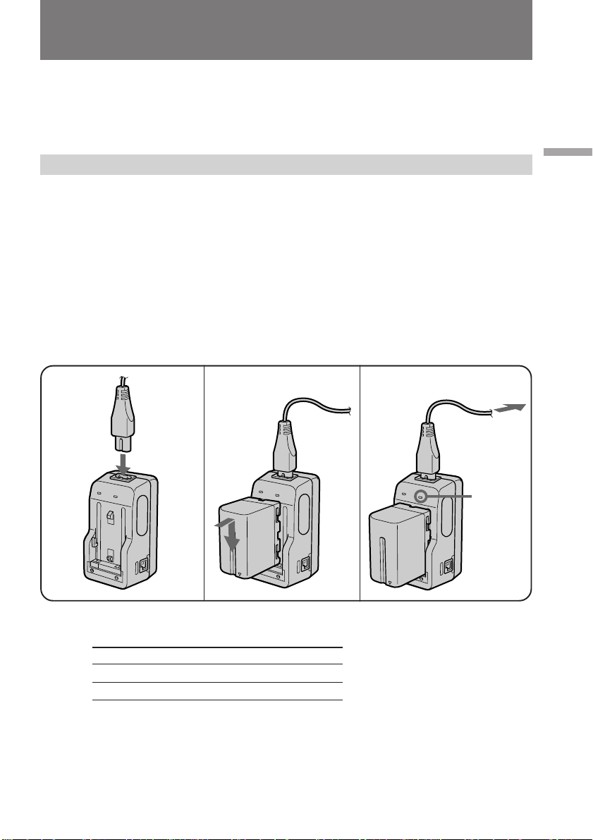
Charging the battery pack
Charge the battery pack on a flat surface without vibration.
(1) Connect the power cord to the AC power adaptor.
(2) Align the surface of the battery pack indicated by the z mark with the edge of
the terminal shutter of the AC power adaptor. Then fit and slide the battery
pack in the direction of the arrow.
(3) Connect the AC power cord to a wall outlet. The CHARGE lamp (orange)
lights up. Charging begins.
When the CHARGE lamp goes out, normal charge is completed. For full charge,
which allows you to use the battery longer than usual, leave the battery pack in place
for approximately one hour. Unplug the unit from the wall outlet, then remove the
battery pack and install it into the digital camcorder. You can also use the battery pack
before it is completely charged.
Getting started
1
2
3
Charging time
Battery pack Charging time* (min.)
NP-F950 360 (300)
NP-F750 270 (210)
The time required for a normal charge is indicated in parentheses.
* Approximate minutes to charge an empty battery pack using the AC-V615 AC power
adaptor. (Lower temperatures require a longer charging time.)
CHARGE
21
Page 22
Charging and installing the battery pack
Battery life
Battery Continuous Typical recording
pack recording time
NP-F950 150 (135) 80 (70)
NP-F750 95 (85) 50 (45)
NP-F950 (x3)3)450 (405) 240 (210)
Numbers in parentheses indicate the time when you use a normally charged battery.
Battery life will be shorter if you use the digital camcorder in a cold environment.
1) Approximate continuous recording time indoors.
2) Approximate minutes when recording while you repeat recording start/stop,
zooming and turning the power on/off. The actual battery life may be shorter.
3) When using the NPA-10000 battery adaptor.
1)
time
2)
To remove the battery pack
Slide the battery pack in the direction of the arrow.
22
Notes on charging the battery pack
•The CHARGE lamp will remain lit for a while even if the battery pack is removed and
the power cord is unplugged after charging the battery pack. This is normal.
•If the CHARGE lamp does not light, disconnect the power cord. After about one
minute, reconnect the power cord again.
•When operating the digital camcorder using the AC power adapter, you cannot
charge the battery pack.
•When a fully charged battery pack is installed, the CHARGE lamp will light once,
then go out.
Page 23
Charging and installing the battery pack
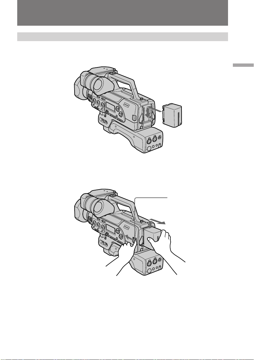
Installing the battery pack
Insert the battery pack in the direction of the $ mark on the battery pack. Slide the
battery pack down until it catches on the battery release and clicks.
To remove the battery pack
While pressing BATT, lift the battery pack out in the direction of the arrow.
Getting started
BATT
23
Page 24

Inserting a cassette
Use a standard DVCAM cassette with logo*.
Make sure that a power source is installed.
We recommend you set the POWER switch to ON before inserting the cassette.
(1) Open the cassette compartment cover.
(2) Insert a cassette (not supplied) with the tab upwards, and the window facing
out and press down so that the cassette loads.
(3) Close the cover.
Note on the cassette
Mini DVCAM cassettes and Mini DV cassettes cannot be used.
* is a trademark.
1
3
2
EJECT6
24
Page 25
Inserting a cassette
To eject the cassette
Open the cassette compartment cover and press 6. After the cassette rises, take it out,
then close the cover.
You cannot eject the cassette while C MEMORY appears in the viewfinder because the
digital camcorder is still writing information into the cassette memory. After C
MEMORY disappears the cassette automatically rises.
When ejecting the cassette, never close the cassette compartment cover until the cassette
is completely removed.
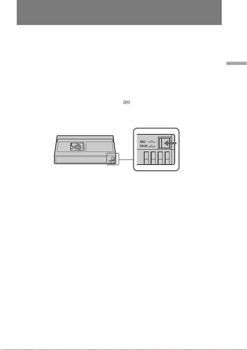
To prevent accidental erasure
Slide the tab on the cassette to expose the red mark. If you insert the cassette with the
red mark exposed, the beeps sound, the and 6 indicators flash in the viewfinder
and display window, and you cannot record.
To re-record on this tape, slide the tab back out, covering the red mark.
Getting started
25
Page 26
Basic operations
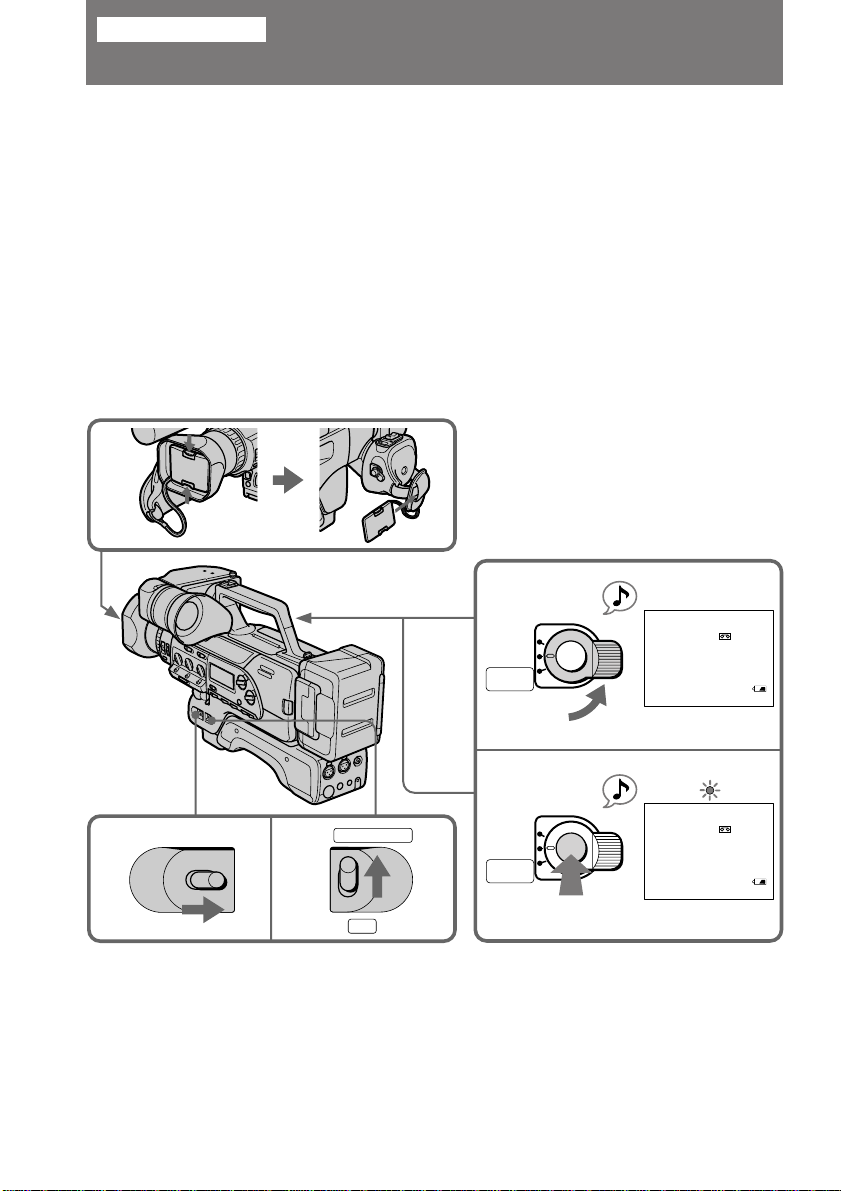
Camera recording
Make sure that the power source is installed and a cassette is inserted and that AUTO
LOCK is set to ON. When AUTO LOCK is set to ON, all settings are automatically
adjusted to best suit your shooting environment. Before you record one-time events,
you may want to make a trial recording to make sure that the digital camcorder is
working correctly.
When you use the digital camcorder for the first time, power on it and reset the date
and time to your time before you start recording (p. 80).
(1) Remove the lens hood cap, and attach it to the grip strap.
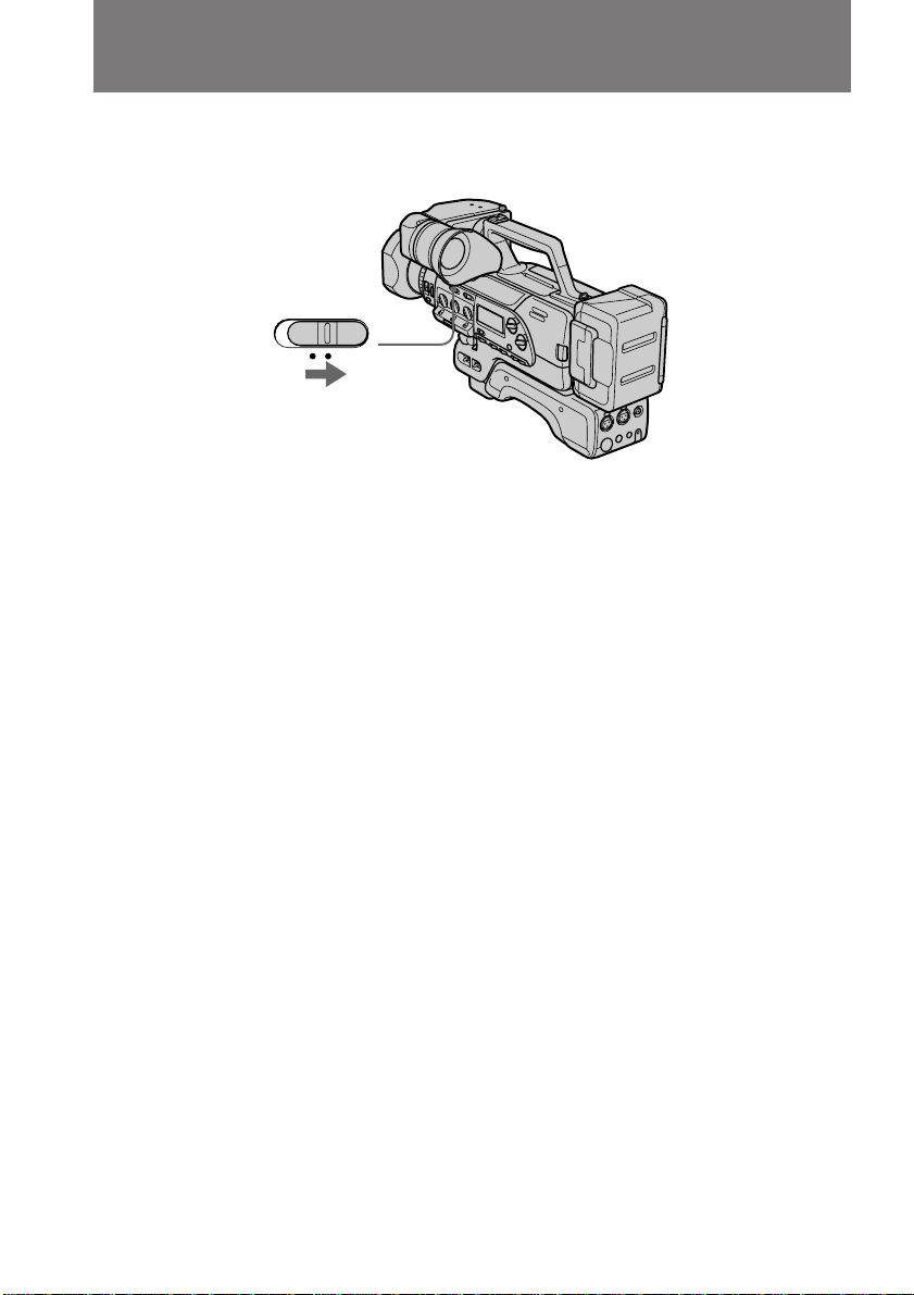
(2) Set the POWER switch to ON.
(3) Set CAMCORDER/VTR to CAMCORDER.
(4) Turn STANDBY up to STANDBY.
(5) Press START/STOP.
The digital camcorder starts recording. The “REC” indicator appears and the
red lamp lights up in the viewfinder. The tally lamps located on the front and
rear also light up.
1
4
LOCK
STANDBY
PHOTO
STANDBY
START/STOP
STBY
0 : 00 : 00 : 00
184 min
26
POWER
23
POWER
OFF ON
CAMCORDER
VTR
5
LOCK
STANDBY
PHOTO
STANDBY
START/STOP
REC
0 : 00 : 00 : 01
184 min
Page 27
Camera recording
When ND ON flashes in the viewfinder
Set ND FILTER to ON.
To stop recording momentarily [a]
Press START/STOP again. The “STBY” indicator appears in the viewfinder (Standby
mode).
To finish recording [b]
Press START/STOP again. Turn STANDBY down to LOCK, and set the POWER switch
to OFF. Then, eject the cassette and remove the battery pack.
[a] [b]
LOCK
STANDBY
PHOTO
STANDBY
START/STOP
STBY
0 : 13 : 46 : 00
170 min
To focus the viewfinder lens [c]
If you cannot see the indicators in the viewfinder clearly, or after someone else has used
the digital camcorder, focus the viewfinder lens. Turn the viewfinder lens adjustment
ring so that the indicators in the viewfinder come into sharp focus.
To adjust the contrast and the brightness of the viewfinder [d]
To adjust the contrast, turn the CONTR knob.
To adjust the brightness, turn the BRIGHT knob.
If you want to turn off the tally lamp [d]
Set TALLY to OFF.
The rear tally lamp cannot be turned off.
[c]
[d]
BRIGHT
TALLY
CONTR
LOCK
STANDBY
PHOTO
STANDBY
START/STOP
LOCK
STANDBY
PHOTO
STANDBY
Basic operations
START/STOP
27
Page 28
Camera recording
To erase the indicators in the viewfinder
You can erase the indicators in the viewfinder except for menu and warning indicators.
Set VF DISPLAY to OFF.
VF DISPLAY
ON OFF
Note on recording
When you record from the beginning of a tape, run the tape by recording for about 15
seconds before you start the actual recording. This will ensure that you won’t miss any
start-up scenes when you play back the tape.
Note on Standby mode
If you leave the digital camcorder in Standby mode for 5 minutes while a cassette is
inserted, the digital camcorder turns off automatically. This prevents wearing down the
battery and wearing out the tape. To resume Standby mode, turn STANDBY down and
up again. To start recording, press START/STOP.
28
Note on time code display
While recording or playing back, the time code shows hours, minutes, seconds and
frame number (0:00:00:00). If there is a blank portion between pictures on a tape, the
time code restarts from zero. You cannot rewrite the time code only.
You can select the drop frame or non-drop frame system. Set DF or NDF using the TC
switch inside the cover of the video control buttons.
You can erase only time code display in the viewfinder. Set TC IND in the menu to OFF.
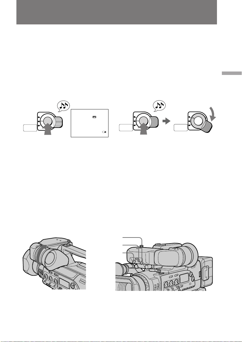
Note on the beep sound
As indicated with ≥ in the illustration, a beep sounds when you turn the power on or
when you start recording, and two beeps sound when you stop recording, confirming
the operation. Several beeps also sound as a warning of any unusual condition of the
digital camcorder.
Note that the beep sound is not recorded on the tape. If you do not want to hear the
beep sound, select “OFF” in the menu system.
Page 29
Camera recording
To change the directionality of the built-in microphone
Set DIRECTION SELECT on the back of the microphone to the desired position (0°/
90°/120°).
To record through an external microphone
Connect a microphone (not supplied) to the MIC (PLUG IN POWER) jack or AUDIO IN
input jacks. You can also attach a microphone to the accessory shoe or to the
microphone holder (not supplied). Then select the input mode using the LINE/MIC
switches. In this case, sound from the built-in microphone will not be recorded.
When the microphone has Connect to Set LINE/MIC to
Mini-plug MIC (PLUG IN POWER) MIC FRONT
XLR connector AUDIO IN (CH-1/CH-2) MIC REAR
To monitor the sound while recording
Use headphones or the built-in speaker. To turn on the built-in speaker, set SPEAKER
to ON. To use headphones, connect them to the 2 jack. Use the MONITOR LEVEL dial
to adjust the volume of the speaker or headphones. When using headphones the builtin speaker becomes inactive.
When monitoring the built-in speaker, feedback may occur. In this case, turn down the
MONITOR LEVEL or SPEAKER set to OFF.
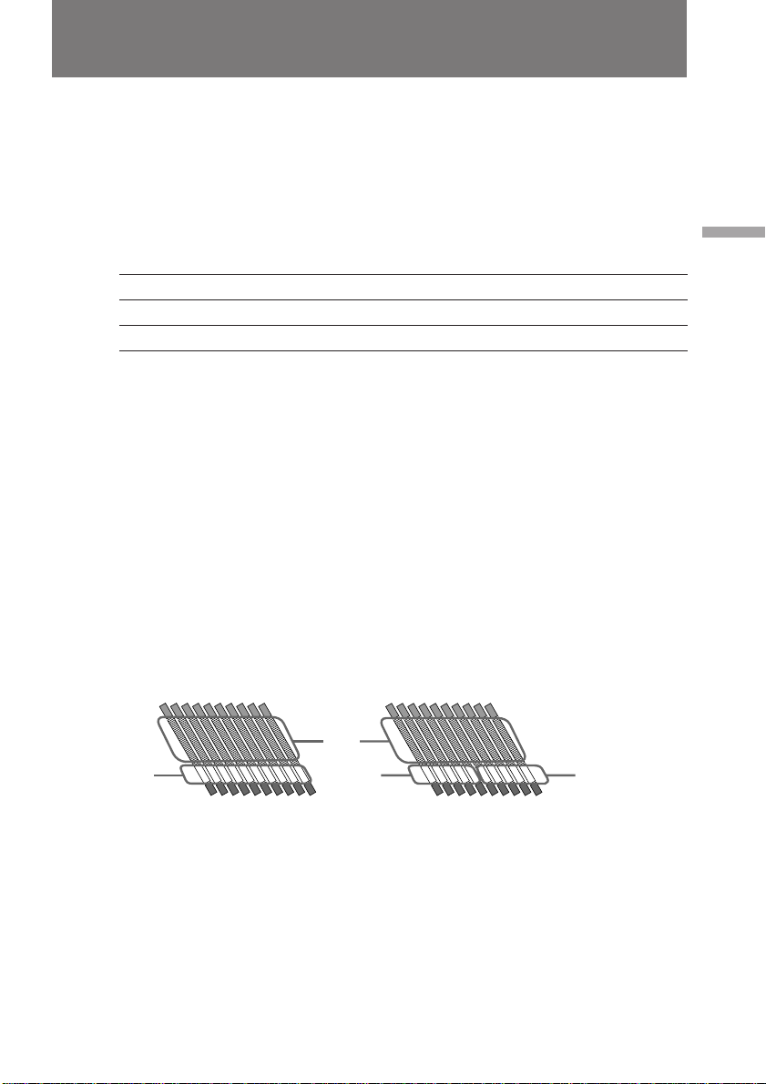
To select Fs 48k [a] or Fs 32k [b] recording mode
Set AUDIO MODE to Fs 48k (16 bit) so that you can get higher sound quality. In Fs 48k
mode, the digital camcorder records one video sector [c] and one audio sector [d]. In
the viewfinder the “48k” indicator appears.
Set AUDIO MODE to Fs 32k (12 bit), and 1 sector is left open for audio dubbing
afterwards. In Fs 32k mode, the digital camcorder records one video sector [c], one
audio sector [d], and one blank audio sector [e], which enables you to add narration or
music after the initial recording.
Basic operations
[d]
[a]
[c]
[e]
[b]
[d]
29
Page 30

Camera recording
Using the zoom feature
Zooming is a recording technique that lets you change the size of the subject in the
scene.
“T” side: for telephoto (subject appears closer)
“W” side: for wide-angle (subject appears farther away)
T
W
W
T
T
W
Zooming speed (Variable speed zooming)
Press the power zoom button a little for a slower zoom, press it more for a faster zoom.
When you shoot a subject using a telephoto zoom
If you cannot get a sharp focus while in extreme telephoto zoom, press the power zoom
button to the “W” side until the focus is sharp. You can shoot a subject that is at least
about 2 5/8 feet (about 80 cm) away from the lens surface in the telephoto position, or
about 1/2 inch (about 1 cm) away in the wide-angle position.
To use digital zoom
Set DIGITAL F in the menu system to ZOOM/WIDE. Then set D ZOOM in the menu
system to ON.
Notes on digital zoom
•More than 10x zoom is performed digitally and the picture quality deteriorates as you
go toward the “T” side.
•The upper side [a] of the power zoom indicator shows the digital zooming zone, and
the lowerside [b] shows the optical zooming zone. If you set the D ZOOM function to
OFF, the [a] zone disappears.
[a]
T
T
30
[b]
W
W
Page 31

120°
90°
Hints for better shooting
When shooting with the digital camcorder on your shoulder, you’ll get better results by
holding the digital camcorder according to the following suggestions:
•Place the digital camcorder on your shoulder and secure it with the grip strap so that
you can easily manipulate the controls with your thumb.
•To adjust the grip, loosen the grip screw [a] with a coin, rotate the grip, and then
tighten the screw. Set the grip to one of the three different position marks.
[a]
1
3
•Place your right elbow against your side.
•Place your left hand under the digital camcorder to support it. Be sure to not touch the
built-in microphone.
•Place your eye firmly against the viewfinder eyecup.
•Use the viewfinder frame as a guide to determine the horizontal plane.
•You can also record in a low position to get an interesting angle. Lift the viewfinder
up for recording from a low position [b].
•While recording in a low position, you can use the front START/STOP button [c].
•You can rotate the viewfinder 120° up and 90° down. This is useful when recording in
a high or low position [d].
Basic operations
2
[b] [d][c]
START/STOP
31
Page 32

Hints for better shooting
•You can move the viewfinder up to about 1 3/16 inches (30 mm) laterally. Turn the
lock ring to release the viewfinder, and then move it. Turn back the lock ring to fix the
viewfinder in place [e].
•You can move the viewfinder up to about 1 3/16 inches (30 mm) lengthwise. Turn the
lock lever under the viewfinder to release it, and then move the viewfinder. Turn back
the lock lever to fix the viewfinder in place [f].
[e]
Caution on carrying
Do not pick up the digital camcorder by anything other than the grip or handle [g].
Caution on the viewfinder
Do not place the digital camcorder so as to point the viewfinder toward the sun. The
inside of the viewfinder may be damaged.
Be careful when placing the digital camcorder under sunlight or by a window [h].
[f]
Release
Lock
[g][h]
32
Note on the viewfinder
When attaching the video light (not supplied) to the accessory shoe, do not lift the
viewfinder. The video light heat may damage the eyecup.
Page 33

Checking the recorded picture
Using EDITSEARCH, you can review the last recorded scene or check the recorded
picture in the viewfinder.
(1) Set the POWER switch to ON and then set CAMCORDER/VTR to
CAMCORDER.
(2) Turn STANDBY up to STANDBY.
(3) Press the – (Œ) side of EDITSEARCH momentarily; the last few seconds of the
recorded portion play back (Rec Review).
Hold down the – side of EDITSEARCH until the digital camcorder goes back
to the scene you want. The last recorded portion is played back. To go forward,
hold down the + side (Edit Search).
Basic operations
1
3
POWER
OFF ON
CAMCORDER
VTR
EDITSEARCH
EDITSEARCH
2
STANDBY
PHOTO
STANDBY
START/STOP
LOCK
EDITSEARCH
To stop playback
Release EDITSEARCH.
To begin re-recording
Press START/STOP. Re-recording begins from the point you released EDITSEARCH.
Provided you do not eject the cassette, the transition between the last scene you
recorded and the next scene you record will be smooth.
Note on the EDITSEARCH
If you press EDITSEARCH fully, the playback speed doubles.
33
Page 34

Connections for playback
You can use this digital camcorder as a VCR by connecting it to monitor for playback.
There are some ways to connect the digital camcorder to monitor. When monitoring the
playback picture by connecting the digital camcorder to monitor, we recommend you to
use house current for power source.
Connecting directly to a monitor with Video/Audio input jacks
If you connect directly to a monitor
Open the jack cover and connect the digital camcorder to the inputs on the monitor by
using the supplied A/V connecting cable.
S VIDEO OUT
[a]
VIDEO OUT
[b]
AUDIO OUT
: Signal flow
If you are going to connect the digital camcorder using the S video cable [a], you do not
need to connect the yellow (video) plug of the A/V connecting cable [b].
S VIDEO IN
VIDEO IN
AUDIO IN
34
Page 35

Connections for playback
If your monitor is already connected to a VCR
Open the jack cover and connect the digital camcorder to the LINE IN inputs on the
VCR by using the supplied A/V connecting cable. Set the input selector on the VCR to
LINE. Set the monitor/VCR selector on the monitor to VCR.
Basic operations
S VIDEO OUT
[a]
VIDEO OUT
[b]
AUDIO OUT
: Signal flow
If your monitor or VCR has a BNC jack
When connecting video output using BNC cable, connect to the rear VIDEO OUT jack.
In this connection, you need not connect S video cable nor the yellow (video) plug of
the A/V connecting cable.
If your monitor or VCR is a monaural type
Connect only the white plug for audio on both the digital camcorder and the monitor.
With this connection, the sound is monaural.
To connect to a TV without Video/Audio input jacks
Use the RFU-95UC RFU adaptor (not supplied).
S VIDEO IN
VCR
AUDIO INVIDEO IN
35
Page 36

Playing back a tape
You can monitor the playback picture in the viewfinder. You can also monitor the
picture on a monitor screen, after connecting the digital camcorder to a monitor or VCR.
(1) Set the POWER switch to ON.
(2) Set CAMCORDER/VTR to VTR.
(3) Insert the recorded tape with the window facing out.
(4) Open the cover, then press · to start playback.
1
2
4
POWER
OFF ON
CAMCORDER
VTR
STOP REW PLAY FF PAUSE
To stop playback, press π.
To rewind the tape, press 0.
To fast-forward the tape rapidly, press ).
REC
3
To monitor the sound while viewing the playback picture in
the viewfinder
Connect headphones (not supplied) to the 2 jack or turn on the built-in speaker by
setting SPEAKER to ON.
36
Using the Remote Commander
You can control playback using the supplied Remote Commander. Before using the
Remote Commander, insert the size AA (R6) batteries.
Note on the DISPLAY button on the remote commander
Press DISPLAY to display the screen indicators on the monitor screen. To erase the
indicators, press DISPLAY again.
Page 37

Playing back a tape
Note on DV-formatted tapes
You can play back DV-formatted tapes on this digital camcorder if the tape is recorded
in SP mode. “DV” appears in the viewfinder during playback.
You cannot play back DV-formatted tapes recorded in LP mode.
Various playback modes
To view a still picture (playback pause)
Press P during playback. To resume playback, press P or ·.
To locate a scene (picture search)
Keep pressing 0 or ) during playback. To resume normal playback, release the
button.
To monitor the high-speed picture while advancing the tape or
rewinding (skip scan)
Keep pressing 0 while rewinding or ) while advancing the tape. To resume
normal playback, press ·.
To view the picture at 1/5 speed (slow playback)
Press & during playback. To resume normal playback, press ·. If slow playback lasts
for about 1 minute, it shifts to normal speed automatically.
To view the picture at double speed
For double speed playback in the reverse direction, press '/<, then press x2 on the
Remote Commander during playback. For double speed playback in the forward
direction, press >/7, then press x2 during playback. To resume normal playback,
press ·.
To view the picture frame-by-frame
Press '/< or >/7 in playback pause mode. If you keep pressing the button, you
can view the picture at 1/30 speed. To resume normal playback, press ·.
To change the playback direction
Press '/< for reverse direction or >/7 for forward direction during playback. To
resume normal playback, press ·.
Basic operations
Notes on playback
•Streaks appear and the sound is muted in the various playback modes.
•When playback pause mode is left on for 5 minutes, the digital camcorder
automatically enters stop mode.
•When using playback slow or still picture modes, images from the previous frames
might to seen mixed in with the main picture.
37
Page 38

Advanced operations
Using alternative power sources
You can choose any of the following power sources for your digital camcorder: battery
pack and the house current. Choose the appropriate power source depending on where
you want to use your digital camcorder.
Place
Indoors
Outdoors
Note on AC power adaptor
Use the recommended AC power adaptor, such as AC-V615.
Note on power sources
Disconnecting the power source or removing the battery pack during recording or
playback may damage the inserted tape. If this happens, restore the power supply again
immediately.
Power source
House current
Battery pack
Using the house current
(1) Connect the power cord to the AC power adaptor.
(2) Connect the power cord to a wall outlet, then connect the connecting cord (not
supplied) to the DC OUT jack on the AC power adaptor.
(3) Connect the connecting cord to the DC IN jack on the digital camcorder.
1
2 3
Accessory to be used (not supplied)
AC power adaptor AC-V615
Battery pack NP-F950, NP-F750
Battery adaptor NPA-10000
DC IN
38
DC OUT
Page 39

Using alternative power sources
Charging the attached battery pack
After connecting the power cord to the wall outlet and setting the POWER switch on
the digital camcorder to OFF, you can charge the battery pack in either of the following
two ways:
•Charging the battery pack attached to the digital camcorder
Leave the battery pack attached to the digital camcorder. (The NP-F950 battery pack
(not supplied) requires about 390 minutes for a full charge and about 330 minutes for
a normal charge.)
While charging, the battery indicator appears repeatedly in the display window:
•Charging two battery packs at the same time
Attach one battery pack to the AC power adaptor and the other to the digital
camcorder. Both are charged simultaneously. When charged, CHARGE lamp and the
ı indicator goes out (normal charge). If either lamp is still lit, both battery packs are
not charged (the NP-F950 battery packs (not supplied) require about 480 minutes for a
full charge and about 420 minutes for a normal charge).
To remove the adaptor
Pull out by the plug. Never pull on the connecting cord itself.
WARNING
The power cord must only be changed at a qualified service shop.
PRECAUTION
The set is not disconnected from the AC power source (mains) as long as it is connected
to the wall outlet, even if the set itself has been turned off.
Advanced operations
Notes on the VTR/CAMERA lamp
•The VTR/CAMERA lamp will remain lit for a while even if the unit is unplugged
after use. This is normal.
•If the VTR/CAMERA lamp does not light, disconnect the power cord. After about one
minute, reconnect the power cord.
This mark indicates that this product is a genuine accessory for Sony
video products.
When purchasing Sony video products, Sony recommends that you
purchase accessories with this “GENUINE VIDEO ACCESSORIES”
mark.
39
Page 40

Changing the mode settings
You can change the mode settings in the menu system to further enjoy the features and
functions of the digital camcorder.
(1) Open the cover, then press MENU to display the menu.
(2) Press
(3) Press
For some items, you may need to repeat steps 2 and 3.
(4) Press MENU to erase the menu display.
or to select the desired item, then press EXECUTE.
or to select the desired setting, then press EXECUTE.
1
MENU
CAMCORDER
MENU
DIGITAL F ZOOM/WIDE
D ZOOM
16:9WIDE
ZEBRA
TC IND
DATE/TIME
COMMANDER
[ MENU ] : END
VTR
MENU
TC IND ON
COMMANDER
BEEP
AUDIO MIX
WIDE PB
CM SEARCH
DATA CODE
[ MENU ] : END
2
3
1
2
EXECUTE
1
2
EXECUTE
MENU
DIGITAL F ZOOM/WIDE
D ZOOM
16:9WIDE
MENU
ZEBRA
TC IND
DIGITAL F
DATE/TIME
D ZOOM OFF
COMMANDER
16:9WIDE
ZEBRA
[ MENU ] : END
TC IND
MENU
DATE/TIME
COMMANDER
DIGITAL F
D ZOOM
[ MENU ] : END
16:9WIDE
ZEBRA OFF
TC IND
DATE/TIME
COMMANDER
[ MENU ] : END
MENU
ZEBRA
[ MENU ] : END
MENU
ZEBRA
[ MENU ] : END
MENU
DIGITAL F
D ZOOM
16:9WIDE
ZEBRA ON
TC IND
DATE/TIME
COMMANDER
[ MENU ] : END
OFF
ON
OFF
ON
40
Page 41

Changing the mode settings
Selecting the mode setting of each item
Items for both CAMCORDER and VTR modes
TC IND* <ON/OFF>
•Normally select ON.
•Select OFF to erase the time code indicator.
COMMANDER* <VTR4/OFF/ID/ID SET>
•Normally select VTR4.
•Select OFF when not using the Remote Commander.
•Select ID when using the Remote Commander with the ID number set.
•Select ID SET when setting the ID number of the Remote Commander.
BEEP* <ON/OFF>
•Select ON so that beeps sound when you start/stop recording, etc.
•Select OFF when you do not want to hear the beep sound.
CLOCK SET*
Reset the date and time.
Items for CAMCORDER mode only
DIGITAL F* <ZOOM/WIDE or OVERLAP>
•Select ZOOM/WIDE before using the wide mode function, digital zoom or slow
shutter.
•Select OVERLAP before using the overlap function.
D ZOOM* <OFF/ON>
Before turning on D ZOOM, set DIGITAL F to ZOOM/WIDE.
•Select OFF to not use the digital zoom.
•Select ON to activate digital zooming. More than 10x zoom is performed digitally.
Advanced operations
16:9WIDE* <OFF/ON>
Before turning on 16:9WIDE, set DIGITAL F to ZOOM/WIDE.
•Normally select OFF.
•Select ON to record a 16:9 wide picture to watch on a wide-screen TV.
ZEBRA* <OFF/ON>
•Normally select OFF.
•Select ON to shoot with the zebra pattern displayed in the viewfinder.
DATE/TIME* <OFF/ON>
•Normally select OFF.
•Select ON to display the date and time indicators.
FRAME REC <OFF/ON>
•Normally select OFF.
•Select ON for cut recording.
INT REC <RETURN> <SET> <INTERVAL*/REC TIME*>
•Select RETURN to return to the menu to change other menu items.
•Select SET to set interval recording ON or OFF.
•Select INTERVAL to set or change the interval time for interval recording.
•Select REC TIME to set or change the recording time for interval recording.
41
Page 42

42
Changing the mode settings
SLOW SHTR* <4/8/15/30>
Before setting, turn the SHUTTER SPEED dial to SLOW.
Select a slow shutter speed.
S PRESET* <60/100/250/500/1000/2000/4000/10000>
Before setting, turn the SHUTTER SPEED dial to USER PRESET.
Select a shutter speed.
G PRESET* <–3dB/0dB/3dB/6dB/9dB/12dB/15dB/18dB>
Before setting, turn the GAIN dial to USER PRESET.
Select a gain level.
AGC LIMIT* <OFF/ON>
•Normally select OFF.
•Select ON when shooting a bright subject on a dark background.
This function prevents the digital camcorder from creating picture noise by
controlling excessive automatic gain level.
CUSTOM* <RETURN> <SET> <COLOR LEV/SHARPNESS/WB SHIFT/AE SHIFT>
<RESET>
•Select RETURN to return to the menu to change other menu items.
•Select SET to set custom preset ON or OFF.
•Select COLOR LEV/SHARPNESS/WB SHIFT/AE SHIFT to preset the color intensity
(COLOR LEV), sharpness (SHARPNESS), white balance (WB SHIFT), and brightness
(AE SHIFT) of the picture.
•Select RESET to restore the default settings.
Items for VTR mode only
AUDIO MIX*
When playing back a tape recorded with Fs 32k, select this item to adjust the volume
balance between audio mode ST1 and ST2.
WIDE PB* <OFF/ON>
•Normally select OFF.
•Select ON to playback a picture recorded in the 16:9 wide mode to watch on a
monitor.
CM SEARCH* <ON/OFF>
•Normally select ON to turn on the cassette memory search function.
•Select OFF to search without using the cassette memory function.
DATA CODE* <DATE/CAM or DATE>
•Select DATE/CAM to display date and time, as well as various settings data, of your
recordings.
•Select DATE to display date and time of your recordings.
When DIGITAL F is set to OVERLAP
You cannot set 16:9WIDE and D ZOOM to ON. When you set DIGITAL F to OVERLAP,
16:9WIDE and D ZOOM settings are changed to OFF automatically.
About FRAME REC and INT REC setting
Both settings are automatically set to off when:
•The POWER switch is set to OFF.
•CAMCORDER/VTR is set to VTR.
•Turn STANDBY up to PHOTO STANDBY.
* These settings are retained even when the battery is removed, as long as the lithium
battery is in place.
Page 43

Fade-in and fade-out
When fading in, the picture gradually fades in from black while the sound increases.
When fading out, the picture gradually fades to black while the sound decreases.
To use fade-in and fade-out, press FADER/OVERLAP to display FADER in the
viewfinder.
When fading in [a]
(1) While the digital camcorder is in Standby mode, press FADER/OVERLAP.
The fade indicator starts flashing.
(2) Press START/STOP to start recording. The fade indicator stops flashing.
When fading out [b]
(1) During recording, press FADER/OVERLAP. The fade indicator starts flashing.
(2) Press START/STOP to stop recording. The fade indicator stops flashing, and
then recording stops.
STBY REC
[a]
Advanced operations
1
FADER/
OVERLAP
[b]
STBY REC
2
FADER
OVERLAP
To cancel the fade-in/fade-out function
Before pressing START/STOP, press FADER/OVERLAP until the indicator disappears.
Note on the fade-in/fade-out function
You can not fade-in or fade-out while recording with interval recording, cut recording,
or photo recording.
LOCK
STANDBY
PHOTO
STANDBY
START/STOP
43
Page 44

Overlapping two pictures
When using the overlap function, the picture gradually fades in over a still picture of
the last scene recorded.
(1) While the digital camcorder is in Standby mode, open the cover, then press
MENU to display the menu in the viewfinder.
(2) Press
(3) Press
(4) Press MENU to erase the menu display.
(5) Press FADER/OVERLAP repeatedly until “OVERLAP” appears in the
viewfinder.
(6) Press START/STOP to start recording.
The scene being shot gradually fades in over the still picture of the last
recorded scene.
or to select DIGITAL F, then press EXECUTE.
or to select OVERLAP, then press EXECUTE.
STBY REC
OVERLAP
44
1
MENU
5
MENU
DIGITAL F
D ZOOM
16 : 9WIDE
ZEBRA
TC IND
DATE/TIME
COMMANDER
[ MENU ] : END
ZOOM/WIDE
MENU
23
DIGITAL F
ZOOM/WIDE
OVERLAP
[ MENU ] : END
MENU
DIGITAL F
D ZOOM
16 : 9WIDE
ZEBRA
TC IND
DATE/TIME
COMMANDER
[ MENU ] : END
OVERLAP
6
LOCK
FADER/
OVERLAP
FADER
OVERLAP
To cancel the overlap function
Before pressing START/STOP, press FADER/OVERLAP until the indicator disappears.
Notes on the overlap function
•You cannot use the overlap function while recording with interval recording, cut
recording, or photo recording.
•When in Standby mode select OVERLAP, the digital camcorder automatically goes
into picture search, then the last recorded scene is stored for overlap.
•When you set DIGITAL F to OVERLAP, 16:9WIDE and D ZOOM settings are set to
OFF automatically.
STANDBY
PHOTO
STANDBY
START/STOP
Page 45

Using the wide mode function
You can record a 16:9 wide picture to watch on a 16:9 wide-screen TV.
[b]
[c]
[a]
[d]
In the viewfinder black bands appear at the top and bottom of the screen [a].
On a monitor screen, the picture appears horizontally compressed [b].
When setting WIDE PB to ON in the menu system, you get a cinema-like picture with a
black band at the bottom of the screen [c].
You can watch the picture of normal images on a wide-screen TV [d].
(1) While the digital camcorder is in Standby mode, open the cover, then press
MENU to display the menu in the viewfinder.
(2) Press
(3) Press
(4) Press
(5) Press
(6) Press MENU to erase the menu display.
MENU
1
DIGITAL F
D ZOOM
16 : 9WIDE
MENU
ZEBRA
TC IND
DATE/TIME
COMMANDER
[ MENU ] : END
or to select DIGITAL F, then press EXECUTE.
or to select ZOOM/WIDE, then press EXECUTE.
or to select 16:9WIDE, then press EXECUTE.
or to select ON, then press EXECUTE.
MENU
DIGITAL F
[ MENU ] : END
MENU
DIGITAL F
D ZOOM
16 : 9WIDE
ZEBRA
TC IND
DATE/TIME
COMMANDER
[ MENU ] : END
ZOOM/WIDE
OVERLAP
ZOOM/WIDE
ZOOM/WIDE
2
3
4
5
MENU
16 : 9WIDE
[ MENU ] : END
MENU
DIGITAL F
D ZOOM
16 : 9WIDE
ZEBRA
TC IND
DATE/TIME
COMMANDER
[ MENU ] : END
Advanced operations
OFF
ON
ON
To cancel wide mode
Set 16:9WIDE to OFF in the menu system.
To watch a tape recorded in 16:9 wide mode on a wide-screen TV
Set the screen mode of the wide-screen TV to full mode. For details, refer to the
instruction manual of your TV.
Notes on wide mode
•When you record in 16:9 wide mode, the date and time indicator will be widened on
the wide-screen TV.
•If you dub a tape, the tape is copied in the same mode as the original recording.
•When you set DIGITAL F to OVERLAP, the 16:9WIDE setting is changed to OFF
automatically.
45
Page 46

Photo recording
You can record a still picture like a photograph for about seven seconds. This mode is
useful when you want to enjoy a picture such as a photograph or when you print a
picture using a video printer (not supplied).
(1) Turn STANDBY up to PHOTO STANDBY.
PHOTO appears in the viewfinder.
(2) Keep pressing PHOTO lightly until a still picture appears in the viewfinder.
To change the still picture, release PHOTO, select a still picture again, and then
press and hold PHOTO lightly. PHOTO CAPTURE appears in the viewfinder.
(3) Press PHOTO deeper.
The still picture in the viewfinder is recorded for about seven seconds. The sound
during those seven seconds is also recorded. If you change the POWER switch or
STANDBY to other positions while recording, this operation is performed after
recording.
1 2,
START/STOP
LOCK
STANDBY
PHOTO
STANDBY
3
To use the remote commander to take a photo
If you press the PHOTO button on the Remote Commander when a still picture appears
in the viewfinder, the digital camcorder will record that still picture. However, you
cannot select other still pictures by using this button.
Note on automatic shutter speed adjustment
If AUTO LOCK is ON or AUTO/MANUAL is set to AUTO, the shutter speed is
automatically adjusted up to 1/1000 depending on the environment.
To use a flash
Attach the HVL-F7 video flash unit (not supplied) to the accessory shoe, and then
connect a LANC cable to the l LANC jack.
Note on using a flash
When using a flash, the shutter speed is automatically adjusted to 1/60 if using
automatic adjustment, and if using manual adjustment, we recommend using a shutter
speed of 1/60.
PHOTO
46
Page 47

Interval recording
You can make a time-lapse like recording by setting the digital camcorder to
automatically record and standby sequentially. You can achieve an excellent recording
for flowering, emergence, etc., with this function.
(1) While the digital camcorder is in Standby mode, open the cover, then press
MENU to display the menu in the viewfinder.
(2) Press
(3) Press
(4) Press
(5) Press
(6) Press
The time: 30SEC ˜ 1MIN ˜ 5MIN ˜ 10MIN.
(7) Press
(8) Press
The time: 0.2SEC ˜ 0.5SEC ˜ 1SEC ˜ 2SEC.
(9) Press MENU to erase the menu display.
You can also press
the menu display.
(10)
Press START/STOP to start interval recording.
or to select INT REC, then press EXECUTE.
or to select SET, then press EXECUTE.
or to select ON, then press EXECUTE.
or to select INTERVAL, then press EXECUTE.
or to select the desired waiting time, then press EXECUTE.
or to select REC TIME, then press EXECUTE.
or to select the desired recording time, then press EXECUTE.
to select RETURN, then press EXECUTE to return to
Advanced operations
1
MENU
MENU
DIGITAL F
D ZOOM
16 : 9WIDE
ZEBRA
TC IND
DATE/TIME
COMMANDER
[ MENU ] : END
ZOOM/WIDE
INTERVAL REC
RETURN
2
SET
INTERVAL
REC TIME
[ RETURN ] : MENU
INTERVAL REC
3
SET OFF
ON
[ MENU ] : END
INTERVAL REC
RETURN
4
SET ON
INTERVAL
REC TIME
[ RETURN ] : MENU
INTERVAL REC
5
INTERVAL 30SEC
1MIN
5MIN
10MIN
[ MENU ] : END
6
7
8
To stop interval recording
Press START/STOP twice.
To cancel interval recording
Set the INT REC mode to OFF in the menu system.
Note on interval recording
You cannot do interval recording with photo recording.
If you change the mode as follows, interval recording is cancelled
•Turn STANDBY down to LOCK.
•Set the POWER switch to OFF.
•Set CAMCORDER/VTR to VTR.
INTERVAL REC
RETURN
SET
INTERVAL 5MIN
REC TIME
[ RETURN ] : MENU
INTERVAL REC
REC TIME 0.2SEC
0.5SEC
1SEC
2SEC
[ MENU ] : END
INTERVAL REC
RETURN
SET
INTERVAL
REC TIME 2SEC
[ RETURN ] : MENU
47
Page 48

Cut recording
You can make a recording with a stop-motion animated effect using cut recording. To
create this effect, alternately move the subject a little and make a cut recording. Secure
the digital camcorder and use the Remote Commander for effective cut recording.
(1) While the digital camcorder is in Standby mode, open the cover, then press
MENU to display the menu in the viewfinder.
(2) Press
(3) Press
(4) Press MENU to erase the menu display.
(5) Press START/STOP on the digital camcorder or the Remote Commander to
start cut recording.
The digital camcorder records about 6 frames, then enters recording Standby
mode.
(6) Move the subject, and repeat step 5.
or to select FRAME REC, then press EXECUTE.
or to select ON, then press EXECUTE.
1 2
MENU
MENU
DIGITAL F
D ZOOM
16 : 9WIDE
ZEBRA
TC IND
DATE/TIME
COMMANDER
[ MENU ] : END
ZOOM/WIDE
3
5
To cancel cut recording
Set the FRAME REC mode to OFF in the menu system.
Notes on cut recording
•The portion immediately after cut recording is completed may be longer than four
frames.
•You cannot do cut recording with photo recording.
•The remaining tape indicator may not be accurate if you do cut recording repeatedly.
MENU
FRAME REC OFF
ON
[ MENU ] : END
MENU
ZEBRA
TC IND
DATE/TIME
COMMANDER
BEEP
FRAME REC ON
INT REC
[ MENU ] : END
START/STOP
48
If you change the mode as follows, cut recording is cancelled
•Turn STANDBY down to LOCK.
•Set the POWER switch to OFF or CAMCORDER/VTR to VTR.
Page 49

Selecting automatic or manual mode
The digital camcorder’s automatic functions offer you worry-free operation under most
shooting conditions. But in some circumstances, manual adjustment is better for
creative recording.
You can adjust focus, aperture, shutter speed, gain, and white balance automatically or
manually.
Here’s the overview of each manual adjustment. See the following pages for detailed
information.
To focus manually
Set FOCUS to MANU. You can adjust the focus regardless of the position of the AUTO
LOCK switch. When you want to focus automatically, set FOCUS to AUTO.
To manually adjust aperture, shutter speed, gain, and white
balance
Set AUTO LOCK to OFF. By setting AUTO (AGC, ATW)/MANUAL to MANUAL, you
can adjust each item independently. When you want to adjust each item automatically,
set AUTO/MANUAL to AUTO (AGC, ATW).
Advanced operations
49
Page 50

Selecting automatic or manual mode
When to adjust aperture, shutter speed, and gain manually
When selecting one of aperture, shutter speed, or gain to be adjusted manually and
leaving the remaining two in automatic adjustment, the remaining two automatic
settings adjust their values based on the value of that one manual setting.
In the following cases you should obtain better results by adjusting setting manually.
[a][b][c]
[a] Shooting portraits – adjust aperture manually.
To alter the depth of focus field, softening the background and making the
subject stand out, portrait style.
[b] Shooting sporting events – adjust shutter speed manually.
• To record fast moving objects and protect against blurring of subject.
• To brighten subject in dark situations.
• To prevent the aperture from closing down in unusually bright situations.
[c] Shooting dark environments – adjust gain manually.
• To suppress color distortion when shooting bright objects in dark places.
• To protect against picture distortion when shooting bright objects.
50
Settings for each item
Item
Aperture
Shutter speed
Gain
Selectable steps
13 steps
12 steps
8 steps
Variation of exposure
0.5 EV/step
1 – 2 EV/step
0.5 EV / step
Note on recording in manual mode
We recommend that you adjust the focus and white balance manually.
Relation of aperture, shutter speed and gain
While recording, a picture’s brightness varies by exposure, you need to keep the
exposure fixed to obtain a fixed brightness.
Total EV (exposure) = EV from aperture control
+ EV from shutter speed control
+ EV from gain control
Brighter ˜ Darker
F1.6 ˜ F11, CLOSE
1/4 ˜ 1/10000
+18 dB ˜ –3 dB
Page 51

Focusing manually
When to use manual focus
In the following cases you should obtain better results by adjusting the focus manually.
[a] [b] [c] [d]
•Insufficient light [a]
•Subjects with little contrast - walls, sky, etc. [b]
•Too much brightness behind the subject [c]
•Horizontal stripes [d]
•Subjects through frosted glass
•Subjects beyond nets, etc.
•Bright subject or subject reflecting the light
•Shooting a stationary subject when using a tripod
Advanced operations
51
Page 52

Focusing manually
Focusing manually
When focusing manually, first focus in telephoto before recording, and then reset the
shot length.
(1) Set FOCUS to MANU. The f indicator appears in the viewfinder.
(2) Press the power zoom button on the “T” side so that the bar in the viewfinder
moves all the way to the “T” side.
(3) Turn the focus ring to achieve a sharp focus.
(4) Set the desired shot length using the power zoom button.
FOCUS
1
AUTO
MANU
INFINITY
2
W
T
T
W
Shooting with auto focusing momentarily
Press PUSH AUTO while focusing manually.
Auto focus functions while you are pressing PUSH AUTO.
When you release PUSH AUTO, manual focusing returns.
You can use this feature to switch between two subjects cleanly.
34
PUSH AUTO
W
T
W
T
52
Page 53

Focusing manually
To return to autofocus mode
Set FOCUS to AUTO. The f indicator in the viewfinder disappears.
Shooting in relatively dark places
Shoot at wide-angle after focusing in the telephoto position.
Shooting in fast-moving subjects relatively bright places
Shoot at wide-angle.
To record a very distant subject
Push FOCUS down to INFINITY. The lens focuses on the most distant subject while
FOCUS is held down. When it is released, manual focus mode is resumed.
Use this function when shooting through a window or a screen, to focus on a most
distant subject.
Notes on manual focusing
The following indicators may appear:
when recording a very distant subject.
when the subject is too close to focus on.
When you shoot close to the subject
Shoot at wide-angle.
Advanced operations
53
Page 54

Adjusting the aperture
If the difference between the brightness of the subject and the background is too great,
adjust the aperture manually.
When the aperture opens (lowering the F value), focal point becomes smaller (reducing
depth of field) so that the background will blur and the subject will be in focus [a].
When the aperture closes (raising the F value), focal point becomes greater (increasing
depth of field) so that both background and subject will focus clearly [b].
[a][b]
(1) Set AUTO LOCK to OFF.
(2) Set AUTO/MANUAL at the right of the IRIS dial to MANUAL.
The current aperture setting appears in the viewfinder.
(3) Turn IRIS to adjust the aperture.
Using the dial, you can select F1.6, F2, F2.4, F2.8, F3.4, F4, F4.8, F5.6, F6.8, F8,
F9.6, F11, and CLOSE. The aperture indicator appears in the viewfinder.
If you select CLOSE, the aperture closes completely, and the picture becomes
black (the effect is the same as trying to record with the lens cover attached).
12
ON OFF
AUTO LOCK
AUTO
MANUAL
54
3
O
P
E
N
IRIS
E
S
O
L
C
To return to automatic aperture mode
Set AUTO/MANUAL at the right of the IRIS dial to AUTO.
About the depth of focus field
The depth of focus field is the in-focus range measured from the distance behind a
subject to the distance in front. The depth of focus field can vary with the aperture value
and the focal length. Lowering the F value (larger aperture) reduces the depth of focus
field. Raising the F value (smaller aperture) provides a larger depth of focus field.
Zooming in telephoto position offers a smaller depth of focus field while the depth of
focus field in wide-angle position is greater.
Note on the aperture
When zoom is in telephoto, you can open the aperture as far as F2 (not to F1.6).
Page 55

Adjusting the shutter speed
Adjust the shutter speed to control the picture quality. When recording sports events,
for example, use a high speed shutter to record fast moving objects clearly.
You can select from 6 different shutter speeds SLOW, 60, 100, 250, 1000 and USER
PRESET. SLOW and USER PRESET have their own menus. Refer to “To adjust the
SLOW SHTR (shutter) or S (shutter) PRESET menu items”.
Shutter speed numbers that appear in the viewfinder are inverted. For example, “250”
means 1/250 sec.
(1) Set AUTO LOCK to OFF.
(2) Set AUTO/MANUAL under the SHUTTER SPEED dial to MANUAL.
(3) Turn SHUTTER SPEED to select a shutter speed. Using the dial, you can select
SLOW, 60, 100, 250, 1000, or USER PRESET. The shutter speed indicator
appears in the viewfinder screen.
Advanced operations
2
AUTO
MANUAL
1
ON OFF
AUTO LOCK
To return to automatic shutter speed mode
Set AUTO/MANUAL below the SHUTTER SPEED dial to AUTO.
3
SHUTTER SPEED
100 250
60
SLOW USER
1000
PRESET
55
Page 56

Adjusting the shutter speed
To adjust the SLOW SHTR (shutter) or S (shutter) PRESET menu
items
When you want to make a dark scene look brighter or give an object the appearance of
motion, use a slow shutter. Set the dial to SLOW, then select speed from SLOW SHTR
menu.
When you want to choose a shutter speed, set dial to USER PRESET, then select the
appropriate shutter speed from the S PRESET menu.
The chosen speed data is set into memory. When you dial another setting, (e.g. 100),
then return to USER PRESET or SLOW, the previous speed is selected automatically.
(1) Open the cover, then press MENU to display the menu.
(2) Press
(3) Press
You can select the following shutter speeds:
SLOW SHTR — 4, 8, 15, 30
S PRESET — 60, 100, 250, 500, 1000, 2000, 4000, 10000
(4) Press MENU to erase the menu display.
or to select SLOW SHTR or S PRESET, then press EXECUTE.
or to select a setting, then press EXECUTE.
2
3
SLOW SHTR S PRESET
MENU
4
8
15
SLOW SHTR 30
[ MENU ] : END
MENU
DATE/TIME
COMMANDER
BEEP
FRAME REC
INT REC
SLOW SHTR 4
S PRESET
[ MENU ] : END
MENU
500
1000
2000
4000
S PRESET 10000
[ MENU ] : END
MENU
COMMANDER
BEEP
FRAME REC
INT REC
SLOW SHTR
S PRESET 500
G PRESET
[ MENU ] : END
56
Page 57

Adjusting the shutter speed
To select the Best Shutter Speed
Concerning shooting conditions and brightness, refer to the following chart to adjust
shutter speed accordingly.
Subject
•A golf swing or tennis match in fine weather
•A landscape shot from a moving car or train
•A moving roller coaster in overcast days
•An athletic scene, marathon, etc.
•Indoor sports
•Replacement for the ND2 filter (to halve the exposure)
in situations of glare a sunny beach
or a snow covered mountain.
•Recording pictures with less flicker under a
fluorescent lamp
•In sunny weather (to avoid an out-of-focus picture
due to a small aperture)
Notes on the slow shutter speed
•You cannot use the slow shutter when DIGITAL F in the menu is set to OVERLAP.
•When using slow shutter, focusing can become difficult. In this case set focus to
manual and put the digital camcorder on a tripod.
Note on the high shutter speed
Using high shutter speed can cause the image to darken. So check brightness using the
viewfinder.
Shutter speed
1/500 – 1/10000
1/100 – 1/500
1/100
Advanced operations
57
Page 58

Adjusting the gain
If the picture is too dark even with the aperture fully open, and using the slowest
acceptable shutter speed, adjust the gain to make the picture as bright as necessary.
When shooting night scenes in automatic setting, the picture may become dark. To
brighten the picture the digital camcorder will automatically turn the gain value up,
and picture noise can develop. In this case, adjust the gain in accordance with the
atmosphere of the subject.
(1) Set AUTO LOCK to OFF.
(2) Set AGC/MANUAL under the GAIN dial to MANUAL.
(3) Turn GAIN to adjust the gain.
Using the dial, you can select –3, 0, 3, 6, 9, or USER PRESET. The gain indicator
appears in the viewfinder.
If you turn the dial to USER PRESET (preset gain), the setting you selected in
the menu activates.
58
1
ON OFF
AUTO LOCK
To return to automatic gain mode
Set AGC/MANUAL below the GAIN dial to AGC.
To use the AGC LIMIT function
The AGC LIMIT function prevents the digital camcorder from creating picture noise by
controlling excessive automatic gain level. To use this function, set to ON in the menu
system.
2
3
AGC
MANUAL
GAIN
36
09
-3
USER
PRESET
Page 59

Adjusting the gain
To adjust the G (gain) PRESET menu item
When you want to choose a gain setting higher than 9, select the appropriate level from
the G PRESET menu.
The setting data is set into memory. When you dial another setting, (e.g. 9), then return
to USER PRESET, the previous setting is selected automatically.
(1) Open the cover, then press MENU to display the menu.
(2) Press
(3) Press
You can select the following settings: –3, 0, 3, 6, 9, 12, 15, 18 dB.
(4) Press MENU to erase the menu display.
1
MENU
MENU
DIGITAL F
D ZOOM
16 : 9WIDE
ZEBRA
TC IND
DATE/TIME
COMMANDER
[ MENU ] : END
Note on the gain
If you set gain too high, picture noise results.
or to select G PRESET, then press EXECUTE.
or to select a setting, then press EXECUTE.
ZOOM/WIDE
2
3
MENU
6dB
9dB
12dB
15dB
G PRESET 18dB
[ MENU ] : END
MENU
BEEP
FRAME REC
INT REC
SLOW SHTR
S PRESET
G PRESET 15dB
AGC LIMIT
[ MENU ] : END
Advanced operations
59
Page 60

Adjusting the white balance
White balance is the adjustment to make white subjects look white and to obtain a more
natural color balance. You can obtain better results by adjusting the white balance
manually when lighting conditions change quickly or when recording outdoors, e.g.
neon signs, fireworks.
Selecting the appropriate mode
[a][b][c][d]
∑
∑ one-push white balance mode
•Shooting with lighting condition on the subject set and with the white balance set in a
particular condition
•Monochromatic subject or background [a]
e (3200K) indoor mode
•Lighting conditions change quickly [b]
•A bright place such as a photography studio
•Under sodium or mercury lamps
w (5800K) outdoor mode
•Under a color matching fluorescent lamp
•Recording a sunset/sunrise, just after sunset, just before sunrise [c], neon signs, or
fireworks [d]
60
Page 61

Adjusting the white balance
Adjusting white balance manually
(1) Set AUTO LOCK to OFF.
(2) Set ATW/MANUAL under the WHT BAL dial to MANUAL.
(3) Turn WHT BAL to select a white balance.
Usually select e (3200K) (indoor mode) or w (5800K) (outdoor mode). To fix
the white balance by using one-push white balance, select ∑ and see “
the white balance setting
”.
Locking
2
ATW
MANUAL
3
1
ON OFF
AUTO LOCK
To return to automatic white balance mode
Set ATW/MANUAL below the dial to ATW.
Locking the white balance setting (One-push white balance mode)
When you set the white balance to one-push white balance mode, the setting is locked
and maintained even if lighting conditions change. In addition, if the lithium battery is
installed, the setting is saved for one hour if you remove the power source.
(1) While in Standby mode, set AUTO LOCK to OFF.
(2) Set ATW/MANUAL under the WHT BAL dial to MANUAL.
(3) Turn WHT BAL to ∑. The ∑ indicator appears in viewfinder.
(4) Shoot a white object, such as paper, fully in the viewfinder.
(5) Press WHITE BALANCE ∑ on the front of the digital camcorder.
The ∑ indicator flashes rapidly. When the white balance has been adjusted
and stored in memory, the indicator stops flashing.
WHT BAL
(5800K)
(3200K)
Advanced operations
1
ON OFF
AUTO LOCK
WHITE
BALANCE
5
2
3
ATW
MANUAL
WHT BAL
(5800K)
(3200K)
61
Page 62

Adjusting the white balance
Notes on the ∑ indicator in the viewfinder
•The indicator means:
Slow flashing: white balance is not adjusted.
Fast flashing: white balance is being adjusted (after you pressed WHITE BALANCE
∑).
Lit steady: white balance has been adjusted.
•If the ∑ indicator keeps flashing even when you press WHITE BALANCE ∑, shoot
in automatic white balance mode. Set AUTO LOCK to ON and slide ATW/MANUAL
under the WHT BAL dial to ATW.
Notes on white balance
•When you shoot with studio lighting or video lighting, use e (3200K) (indoor) mode.
•When you shoot under fluorescent lighting, use automatic white balance mode.
Shooting when the lighting condition changes
•After the lighting condition changes, readjust the white balance using the WHITE
BALANCE ∑ button while the digital camcorder is in Standby mode. The WHITE
BALANCE ∑ button does not function during recording.
•If you are adjusting the aperture (iris) and shutter speed manually, then when you
move from indoors to outdoors or vice-versa, set AUTO LOCK to ON and then set it
to OFF again.
•After you move from indoors to outdoors or vice-versa, or detach the battery to
replace it, while shooting in automatic white balance mode, point the digital
camcorder at a white subject for about 10 seconds before you start recording.
62
Page 63

Using the ND filter
The digital camcorder automatically senses the need for the ND filter, in such a case,
ND ON/OFF flashes in the display.
Using the ND filter (to filter down to one-tenth the quantity of light), you can prevent
the picture from going out of focus under bright conditions.
When ND ON flashes in the viewfinder
Set ND FILTER to ON [a].
The flashing indicator disappears, and the ND indicator remains.
When ND OFF flashes in the viewfinder
Set ND FILTER to OFF [b].
The indicator disappears.
[a] [b]
ND
FILTER
ON
OFF
ND ON ND OFF
ND
OFF
ON
FILTER
ND
Advanced operations
63
Page 64

Using the zebra pattern
You can set the digital camcorder to display a zebra pattern (diagonal stripes) [a] in the
portion of the picture in the viewfinder where the brightness exceeds a certain level.
The portion of the picture where the zebra pattern appears is an area of high brightness
and overexposure. You can check the picture level of a subject by displaying the zebra
pattern.
Before you start recording, use the zebra pattern as a guide for adjusting the aperture,
gain, and shutter speed.
(1) Open the cover, then press MENU to display the menu in the viewfinder.
(2) Press
(3) Press
(4) Press MENU to erase the menu display.
or to select ZEBRA, then press EXECUTE.
or to select ON, then press EXECUTE.
1
MENU
MENU
DIGITAL F
D ZOOM
16 : 9WIDE
ZEBRA
TC IND
DATE/TIME
COMMANDER
[ MENU ] : END
ZOOM/WIDE
[a]
2
3
MENU
ZEBRA OFF
ON
[ MENU ] : END
MENU
DIGITAL F
D ZOOM
16 : 9WIDE
ZEBRA ON
TC IND
DATE/TIME
COMMANDER
[ MENU ] : END
Note on shooting with the zebra pattern
Even though you see the zebra pattern in the viewfinder, the zebra pattern is not
recorded.
64
Page 65

Adjusting the recording sound
You can adjust the recording sound level. Use headphones (not supplied) to monitor
the sound when you adjust.
Selecting and setting audio mode
You can record sound using channel 1 and channel 2.
Select sound input using the LINE/MIC switch as follows:
MIC FRONT: When recording from the built-in microphone or external microphone
MIC REAR: When recording from external microphone connected to AUDIO IN CH-
LINE: When recording from line-in connected to AUDIO IN CH-1 or/and CH-
LINE/MIC switches setting and recording sound
LINE/MIC switch
CH-1 CH-2 CH-1 CH-2
MIC FRONT MIC FRONT — Built-in mic: L Built-in mic: R
MIC REAR MIC REAR — XLR MIC XLR MIC
LINE LINE — XLR LINE XLR LINE
* External microphone connected to MIC (PLUG IN POWER) jack. This “–” means no connection.
Notes on recording
•Be sure to set LINE/MIC setting properly, otherwise no sound will be recorded.
•When nothing is connected to the XLR connector and you set the LINE/MIC switch to
MIC REAR, a noise may occur.
•When both CH-1 and CH-2 LINE/MIC switches are set to FRONT, adjust the sound
level using the REC LEVEL dial and switch for CH-1 only.
connected to MIC (PLUG IN POWER) jack.
1 or/and CH-2.
2.
position
LINE — Built-in mic: L+R
MIC REAR — Built-in mic: L+R
LINE — XLR MIC XLR LINE
MIC FRONT — Built-in mic: L+R
MIC FRONT — Built-in mic: L+R
MIC REAR — XLR LINE XLR MIC
Microphone
type*
Stereo External mic: L External mic: R
Monaural External mic: Mono External mic: Mono
Stereo External mic: L+R XLR LINE
Monaural External mic: Mono
Stereo External mic: L+R XLR MIC
Monaural External mic: Mono
Stereo XLR MIC External mic: L+R
Monaural External mic: Mono
Stereo XLR LINE External mic: L+R
Monaural External mic: Mono
Recording
sound
MIC (PLUG IN POWER)
Advanced operations
CH-1 AUDIO IN
CH-2 AUDIO IN
Built-in microphone
CH-1 LINE/MIC
CH-2 LINE/MIC
65
Page 66

Adjusting the recording sound
Checking the recording level
Use the level indicator in the display window.
If the input level is excessive, the PEAK indicator lights. If the PEAK indicator remains
lit, adjust the recording sound manually.
PEAK
REC LEVEL
Adjusting the recording level automatically
Set REC LEVEL to AUTO.
CH-1 REC LEVEL CH-2
AUTO MANUAUTO MANU
Adjusting the recording level manually
(1) Set the REC LEVEL switch to MANU.
(2) Turn the REC LEVEL dials to adjust the sound level so that the PEAK indicator
does not light up. You can adjust the level of each channel separately.
We recommend using headphones (not supplied) to monitor the sound when you
adjust.
Select the sound you want to monitor (CH-1, CH-2 or MIX) using the AUDIO
MONITOR switch.
1
CH-1 REC LEVEL CH-2
AUTO MANUAUTO MANU
2
5
CH-1
REC LEVEL
10
CH-2
0
10
0
5
66
Page 67

Adjusting the recording sound
To attenuate the recording level
Attenuate the recording level when recording very loud sounds.
•When using the built-in microphone or external microphone.
Set the MIC switch to ATT. Normally set off (green position).
•When connecting an external microphone to AUDIO IN (CH-1/CH-2) input
connector.
Set ATT (REAR) to ON.
To reduce wind noise of the built-in microphone
If there is a loud wind, set the BUILT-IN MIC switch to WIND. Note that low frequency
input signal will weaken.
To change the directionality of the built-in microphone
Set DIRECTION SELECT to the desired position (0°/90°/120°).
When set to 0° the sound is in monaural.
Advanced operations
MIC (PLUG IN POWER)
DIRECTION SELECT
MIC
BUILT-IN MIC
AUDIO IN
CH-1 LINE/MIC
CH-1 ATT (REAR)
CH-2 LINE/MIC
CH-2 ATT (REAR)
67
Page 68

Releasing the STEADY SHOT function
When you shoot, the Ó indicator appears in the viewfinder. This indicates that the
Steady Shot function is working and the digital camcorder compensates for camerashake.
When you attach the digital camcorder to a tripod, you need not worry about camerashake.
Release the Steady Shot function.
Set STEADY SHOT to OFF.
STEADY SHOT
ON OFF
To activate the Steady Shot function again
Set STEADY SHOT to ON.
68
Note on the Steady Shot function
The Steady Shot function will not correct excessive camera-shake.
Page 69

Making a custom preset
Use this menu setting to achieve consistent picture quality. This feature lets you
customize the picture quality.
Item
COLOR LEV
SHARPNESS
WB SHIFT
AE SHIFT*
Adjusts
Color intensity
Sharpness
White balance
Brightness
* When the aperture, shutter speed and gain are set manually, AE SHIFT level does
not change.
(1) Open the cover, then press MENU to display the menu in the viewfinder.
(2) Press
or to select CUSTOM, then press EXECUTE.
The custom preset menu appears.
(3) Press
(4) Press
(5) Press
(6) Press
to select SET, then press EXECUTE.
to select ON, then press EXECUTE.
or to select the desired item, then press EXECUTE.
or to adjust the selected mode, then press EXECUTE.
(7) Press MENU to erase the menu display and display
To perform other menu settings, press
EXECUTE.
Adjustment value
Decreases color intensity
˜ Increases color intensity
Softer ˜ Sharper
Bluish ˜ Reddish
Darker ˜ Brighter
Advanced operations
in the viewfinder.
to select RETURN, then press
1
MENU
MENU
DIGITAL F
D ZOOM
16 : 9WIDE
ZEBRA
TC IND
DATE/TIME
COMMANDER
[ MENU ] : END
ZOOM/WIDE
2
3
CUSTOM PRESET
RETURN
SET
COLOR LEV
SHARPNESS
WB SHIFT
AE SHIFT
RESET
[ RETURN ] : MENU
CUSTOM PRESET
SET OFF
ON
[ MENU ] : END
4
5
CUSTOM PRESET
RETURN
SET ON
COLOR LEV
SHARPNESS
WB SHIFT
AE SHIFT
RESET
[ RETURN ] : MENU
CUSTOM PRESET
COLOR LEV
[ MENU ] : END
69
Page 70

Making a custom preset
To turn off custom preset
(1) While the digital camcorder is in Standby mode, press MENU.
(2) Press
(3) Press
(4) Press
(5) Press MENU to erase the menu display.
or to select CUSTOM, then press EXECUTE.
to select SET, then press EXECUTE.
to select OFF, then press EXECUTE.
goes off in the viewfinder.
To turn on custom preset again
(1) While the digital camcorder is in Standby mode, press MENU.
(2) Press
(3) Press
(4) Press
(5) Press MENU to display
or to select CUSTOM, then press EXECUTE.
to select SET, then press EXECUTE.
to select ON, then press EXECUTE.
To restore the standard settings
(1) While the digital camcorder is in Standby mode, press MENU.
(2) Press
(3) Press
FINISHED appears in the viewfinder.
(4) Press MENU to erase the menu display.
or to select CUSTOM, then press EXECUTE.
to select RESET, then press EXECUTE.
To check the custom preset settings
You can display and check the custom preset settings in the viewfinder while recording.
Press CP CHECK on the front of the digital camcorder while the digital camcorder is in
Standby mode or recording mode.
The custom preset settings are displayed in the viewfinder.
Press CP CHECK again to make the display disappear.
in the viewfinder.
70
Note on custom preset
You can turn on custom preset when in automatic mode and also when in manual
mode.
Page 71

Searching the recorded picture
When you use a cassette memory-mounted DVCAM cassette ( logo*) which can
store the recorded date and time, etc., you can search the recorded picture with the date
or time using the Remote Commander (Cassette memory search). You can also search
the photo-recorded pictures only, or the recorded picture in the backward and forward
direction from the present position without cassette memory.
* is a trademark.
Searching the recorded picture with the date or time – Cassette
memory search
(1) Set the POWER switch to ON, then set CAMCORDER/VTR to VTR.
(2) Open the cover, press MENU to display the menu in the viewfinder.
(3) Set CM SEARCH to ON in the menu system.
(4) Press MENU to erase the menu display.
(5) Press SEARCH MODE on the Remote Commander to select date search (search
with the date) or photo search (search the photo recorded-pictures only).
(6) On the Remote Commander, press + to search forward or = to search
backward.
Advanced operations
1
POWER
POWER
OFF ON
CAMCORDER
VTR
5
DATE SEARCH
1 MAY/ 24/98
2 JUN/ 3/98
3 JUN/ 23/98
4 JUL/ 24/98
5 JUL/ 25/98
6 AUG/ 1/98
SEARCH
MODE
PHOTO SEARCH
1 MAY/ 24/98 8:52 PM
2 JUN/ 3/98 10:29 AM
3 JUN/ 23/98 8:12 AM
4 JUL/ 24/98 4:15 PM
5 JUL/ 25/98 9:43 PM
6 AUG/ 1/98 12:05 PM
6
DATE SEARCH
1 MAY/ 24/98
2 JUN/ 3/98
3 JUN/ 23/98
4 JUL/ 24/98
5 JUL/ 25/98
6 AUG/ 1/98
Notes on cassette memory search
•You can search up to 24 days for date search and 179 pictures for photo search when
you use the 16k-bit cassette memory.
•Make sure that the lithium battery is installed if using cassette memory.
PHOTO SEARCH
1 MAY/ 24/98 8:52 PM
2 JUN/ 3/98 10:29 AM
3 JUN/ 23/98 8:12 AM
4 JUL/ 24/98 4:15 PM
5 JUL/ 25/98 9:43 PM
6 AUG/ 1/98 12:05 PM
71
Page 72

Searching the recorded picture
Searching the recorded picture without using cassette memory
(1) Set the POWER switch to ON, then set CAMCORDER/VTR to VTR.
(2) Open the cover, press MENU to display the menu in the viewfinder.
(3) Set CM SEARCH to OFF in the menu system.
(4) Press MENU to erase the menu display.
(5) Press SEARCH MODE on the Remote Commander to select date search (search
with the date) or photo search (search the photo-recorded pictures only).
(6) On the Remote Commander, press + to search forward or = to search
backward.
Each time you press + or =, the digital camcorder searches for the next
scene.
To stop searching
Press π.
If your tape has blank portions between pictures
The digital camcorder may not search for the recorded picture or data may not be
stored.
Notes on searching
•The digital camcorder may not search correctly if the beginning of the search portion
is too close to the tape head position.
•When you use date search, the digital camcorder plays back the search picture, and
when you use photo search, the digital camcorder enters playback pause when it finds
the point it was searching for.
72
Page 73

Displaying recording data
You can display the date and time as well as system data and when you recorded (Data
Code), on the TV during playback or editing. The Data Code is also displayed in the
viewfinder and the display window.
Press DATA CODE on the Remote Commander while playing back. Each time you
press DATA CODE, the indicator cycles in the viewfinder as follows:
When you select DATE/CAM from the menu [a]:
recorded date and time n various settings n no indication
When you select DATE from the menu [b]:
recorded date and time n no indication
Press DATA CODE repeatedly to erase the display.
[a] [b]
Advanced operations
DATA CODE
JUL. 4 1998
10:13:02 AM
AUTO
6 0 ATW
F1.6 0dB
JUL. 4 1998
10:13:02 AM
When bars (--:--:--) appear
•A blank portion of the tape is being played back.
•The tape was recorded by a digital camcorder without the Data Code function.
•The tape was recorded by a digital camcorder without having date and time set.
73
Page 74

Editing onto another tape
You can create your own video programs by editing with any other VCRs that have DV
IN or video/audio inputs. Note that cassette memory data is not recorded on the
edited tape.
You can edit with little deterioration of picture and sound quality when using the DV
connecting cable (not supplied). Data code of the source tape is dubbed on the edited
tape at the same time.
Before editing
Connect DV IN/OUT of the digital camcorder and the DV IN (or DV IN/OUT) jack of
the VCR using the VMC-2DV DV connecting cable (not supplied).
You can use this digital camcorder either as a player or as a recorder without changing
the connection. The direction of signal flow changes automatically.
When this digital camcorder is used as a recorder, the “DV IN” appears in the
viewfinder.
DV IN/OUT
Recorder with DV IN
74
VMC-2DV
: Signal flow
Notes on editing using the DV connecting cable
•When the tape is carried out DV dubbing using a domestic DV equipment to
playback, you might not to be able to edit the tape with editing equipment for
business use such as the DSR-80/85. If you want to edit using such equipment, carry
out dubbing again using it to record.
•Depending on signal conditions, DVCAM-formatted tapes may not be able to edit
using the DV connecting cable. Edit using the supplied A/V connecting cable in this
case.
•You can connect one VCR only.
•If you edit playback pause picture, the edited picture becomes rough.
•Connect a LANC cable (not supplied) to control the playback VCR from the recording
VCR.
DV IN
To connect the VCR without DV IN jack
Connect the digital camcorder to the VCR using the supplied A/V connecting cable.
Set the TV/VCR input selector on the VCR to LINE.
If your VCR is a monaural type, connect only the white plug for audio on both the
digital camcorder and the VCR. With this connection, the sound is monaural.
Page 75

Editing onto another tape
Starting editing
(1) Set the POWER switch to ON and then set CAMCORDER/VTR to VTR.
(2) Insert a blank tape (or a tape you want to record over) into the recording VCR.
Then insert your recorded tape into the digital camcorder.
(3) Play back the recorded tape on the digital camcorder until you locate the point
where you want to start editing. Then set the digital camcorder to playback
pause mode.
(4) Set the recording VCR to recording pause mode.
(5) Press P on the digital camcorder and VCR simultaneously to start editing.
To edit more scenes, repeat steps 3 to 5.
To stop editing
Press π on the digital camcorder and VCR.
Note on editing when using the A/V connecting cable
Press DISPLAY on the Remote Commander while editing onto another tape to turn off
the display indicators. Otherwise, the indicators will be recorded on the tape.
Note on Fine Synchro Edit
If you connect a video deck that has the Fine Synchro Edit feature to the l LANC jack
of the digital camcorder using a LANC cable (not supplied), the edit will be even more
precise.
Advanced operations
75
Page 76

Audio dubbing
If you recorded in Fs 32k (12 bit) recording mode, you can add stereo narration or music
to the recording.
Making connections
To use additional audio line in [a]
Connect the LINE OUT jacks of an audio source to the rear AUDIO IN jacks of the
digital camcorder using an audio connecting cord with the XLR connector (not
supplied) and then set LINE/MIC to LINE.
To use an additional microphone
•Use the built-in microphone [b] or connect an external microphone (not supplied) [c]
to the MIC (PLUG IN POWER) jack, then set LINE/MIC to MIC FRONT.
•Use an external microphone (not supplied) with the XLR connector [d], connect the
rear AUDIO IN jack of the digital camcorder, then set LINE/MIC to MIC REAR.
Audio source
[a]
76
MIC
MIC
: Signal flow
[c]
[b]
[d]
Page 77

Audio dubbing
Recording
(1) Set the POWER switch to ON and then set CAMCORDER/VTR to VTR.
(2) Open the cover, press ·, then ) or 0, to search for the start and end
points of the recording.
(3) Press P at the start point of the recording.
(4) Press AUDIO DUB
(5) Adjust the recording volume.
(6) Press P.
Audio dubbing begins.
If you are using an audio source input, press P on the stereo at the same time.
2
REW PLAY FF
.
REC LEVEL
4
AUDIO
DUB
Advanced operations
3,
6
PAUSE
Audio source
: Signal flow
To stop recording
Press π.
To pause recording
Press P. To start recording again, press P.
To adjust the volume
If you set REC LEVEL to AUTO, the volume is automatically adjusted.
To adjust the volume manually, set REC LEVEL to MANU, and turn the REC LEVEL
dials.
Note on audio dubbing
You cannot operate audio dubbing on DV-formatted tapes. Depending on signal
conditions, you may not be able to operate audio dubbing even on DVCAM-formatted
tapes.
77
Page 78

Additional information
Changing the lithium battery in the digital
camcorder
Your digital camcorder is supplied with a lithium battery installed. When the battery
becomes weak or dead, the I indicator flashes in the viewfinder for about 5 seconds
when you set the digital camcorder to CAMCORDER mode with the POWER switch
ON. In this case, replace the battery with a Sony CR2025 or Duracell DL-2025
lithium battery. Use of any other battery may present a risk of fire or explosion.
The lithium battery for the digital camcorder lasts for about 1 year under normal
operation. (The lithium battery that comes installed at the factory may not last 1 year.)
Notes on lithium battery
• Keep the lithium battery out of the reach of children.
Should the battery be swallowed, immediately consult a doctor.
•Wipe the battery with a dry cloth to assure a good contact.
•Do not hold the battery with metallic tweezers, otherwise a short-circuit may occur.
•The lithium battery has positive (+) side and negative (–) side as illustrated. Be sure
to insert the lithium battery with the positive side facing out.
78
2
0
2
0
5
2
R
C
(+)
5
2
R
C
(–)
WARNING
The battery may explode if mistreated. Do not recharge, disassemble, or dispose of in
fire.
Page 79

Changing the lithium battery in the digital camcorder
Changing the lithium battery
When replacing the lithium battery, keep the battery pack or other power source
attached. Otherwise, you will need to reset the date, time and other items in the menu
system retained by the lithium battery.
(1) Open the lid of the lithium battery compartment.
(2) Push the lithium battery down once and pull it out from the holder.
(3) Install the lithium battery with the positive (+) side facing out. Close the lid.
1 2 3
Additional information
C
R
2
0
2
5
79
Page 80

Resetting the date and time
You can reset the date and time in the menu system.
(1) Open the cover, then press MENU to display the menu.
(2) Press
(3) Press
month, hour, and minutes by pressing
(4) Press MENU to erase the menu display.
to select CLOCK SET, then press EXECUTE.
or to select the desired year, then press EXECUTE. Set the day,
/ and then pressing EXECUTE.
1 2
MENU
MENU
DIGITAL F
D ZOOM
16 : 9WIDE
ZEBRA
TC IND
DATE/TIME
COMMANDER
[ MENU ] : END
ZOOM/WIDE
3
1
2
3
4
5
MENU
INT REC
SLOW SHTR
S PRESET
G PRESET
AGC LIMIT
CUSTOM
CLOCK SET - - : - - : - -
[ MENU ] : END
1999 JAN 1
CLOCK SET 12 00 AM
MENU
[ MENU ] : END
1999 JUL 1
CLOCK SET 12 00 AM
MENU
[ MENU ] : END
1999 JUL 4
CLOCK SET 12 00 AM
MENU
[ MENU ] : END
1999 JUL 4
CLOCK SET 8 00 AM
[ MENU ] : END
MENU
1999 JUL 4
CLOCK SET 8 20 AM
[ MENU ] : END
MENU
1998 JAN 1
CLOCK SET 12 00 AM
[ MENU ] : END
1999 JAN 1
CLOCK SET 12 00 AM
MENU
[ MENU ] : END
1999 JUL 1
CLOCK SET 12 00 AM
MENU
[ MENU ] : END
1999 JUL 4
CLOCK SET 12 00 AM
MENU
[ MENU ] : END
1999 JUL 4
CLOCK SET 8 00 AM
[ MENU ] : END
MENU
INT REC
SLOW SHTR
S PRESET
G PRESET
AGC LIMIT
CUSTOM JUL 4 1999
CLOCK SET 8:20:01 AM
[ MENU ] : END
80
To correct the date and time setting
Repeat the above procedure.
To check the preset date and time
The date and time are shown in the display window. They can only be seen when the
power is on.
The year changes as follows:
1998 ˜ 1999 N · · · · n 2028
n
Note on the time indicator
The internal clock of this digital camcorder operates on a 12-hour cycle.
•12:00 AM stands for midnight.
•12:00 PM stands for noon.
n
Page 81

Compatibility of DVCAM and DV formats
DVCAM format is developed as a more reliable and higher end format than consumer
DV format. Here are explained about DVCAM and DV formats: the differences,
compatibility, and limitations on editing.
Differences between DVCAM and DV formats
Item DVCAM DV
Track pitch 15 µm 10 µm
Audio sampling 12 bit: 32 kHz 12 bit: 32 kHz
frequency 16 bit: 48 kHz 16 bit: 32 kHz, 44.1 kHz, 48 kHz
Audio recording mode 1)Lock mode Unlock mode
Time code Drop frame system or Drop frame system only
1)
There are two modes for audio recording, lock mode and unlock mode. In lock mode,
the sampling frequencies of audio and video are synchronized. In unlock mode, which
consumer DV format adopts, the two sampling frequencies are independent.
Therefore, lock mode is more effective than unlock mode in digital processing and
smooth transition during audio editing.
DVCAM and DV cassettes
Both DVCAM and DV cassettes can be used on DVCAM or DV video equipment. The
recording format of picture is defined according to recorder’s format as described
below.
Recorder’s format Cassette’s format Recording format
DVCAM DVCAM DVCAM
DV DVCAM DV
Non-drop frame system
(SMPTE time code)
DV DVCAM
DV DV
Additional information
This digital camcorder complies with DVCAM format. Though DV cassettes can be
used for recording, we recommend you to use DVCAM cassettes to get the most out of
high reliability of DVCAM format. The recording time of DV cassettes is 2/3 shorter
than that indicated on the DV cassettes.
Compatibility on playback
Some tapes cannot be played back on DVCAM or DV video equipment.
Tape On DV video equipment On DVCAM video equipment
DV-formatted Can be played back Can be played back
(only when recorded in SP mode)
DVCAM-formatted Some equipments may be Can be played back
able to play back
81
Page 82

Compatibility of DVCAM and DV formats
Compatibility on editing using DV connectors
When this digital camcorder is connected to other DVCAM or DV video equipment
using DV connectors, the recording format of edited tapes is defined according to
recorder’s format as described below.
Source tape Player’s format Recorder’s format Recording format
DVCAM-formatted
DVCAM-formatted DVCAM DV DV
DVCAM-formatted
DVCAM-formatted DV
DV-formatted
DV-formatted
DV-formatted DV DVCAM DVCAM
DV-formatted DV DV DV
1)
When using the DVCAM video equipment to carry out DV dubbing of a tape
recorded in DV format, the tape produced will be in DVCAM format as follows:
– Audio recording mode will be unlock mode.
– The time code format will be partly maladjusted. (There will be no effect on the
recorded picture except in certain case.)
2)
If the tape is to be dubbed is DVCAM formatted tape as in 1), the tape produced will
be in DVCAM format as follows:
– Audio recording mode will be unlock mode.
– The time code format will be partly maladjusted.
3)
Depending on signal conditions of the source tape, you may not be able to edit the
tape using the DV connectors.
4)
Audio recording mode of the edited tape is lock mode.
5)
Some DV video equipment may be able to play back a DVCAM-formatted tape. Even
if the tape is played back, contents of the playback cannot be guaranteed.
6)
DV-formatted tapes recorded in SP mode only can be used as source tapes.
7)
Depending on model of video equipment, you may not be able to edit.
2) 3)
DVCAM DVCAM DVCAM
2)
6)
6)
5)
DV
5)
DVCAM DVCAM
DV DV
DVCAM DVCAM DVCAM
DVCAM DV DV
4)
7)
4)
1)
1)
82
Limitations on editing
You will find the following limitations when editing.
• Due to the difference of a track pitch, you cannot record or edit on DV-formatted
tapes using DVCAM video equipment.
• Depending on signal conditions, you may not be able to record or edit on DVCAMformatted tapes.
In these cases, do the following:
• Edit using audio/video jacks.
• Dub a DV-formatted tape using audio/video jacks, then use the dubbed tape as a
source tape.
Page 83

Notes on video cassettes
Usable cassettes
We recommend using a standard DVCAM cassette
You can get the highest quality pictures with this digital camcorder using a standard
DVCAM cassette which is the highest quality cassette.
You may not get as good a quality with lesser cassettes.
You cannot use any other mini DVCAM, mini DV, h 8 mm, H Hi8, j
VHS, k S-VHS, VHSC, K S-VHSC, l Betamax or ¬ ED Betamax type
cassettes.
Copyright signal
When you play back
Using this digital camcorder, you cannot play back a tape that has recorded copyright
control signals for copyright protection of software. “COPY INHIBIT” appears on the
monitor screen or in the viewfinder if you try to play back such a tape. This digital
camcorder does not record copyright control signals on the tape when it records.
When you record
You cannot use this digital camcorder and the DV connecting cable to copy a tape that
has recorded the copyright control signals for copyright protection of software. “COPY
INHIBIT” appears in the viewfinder or on the monitor screen if the playback signal of
such a tape is input to this digital camcorder.
Notes on the DVCAM cassette
Gold-plated connector of the standard DVCAM cassette
If the gold-plated connector of the DVCAM cassette gets dirty or dust sticks to the
connector, the digital camcorder may malfunction when using the cassette memory
functions such as cassette memory search.
Clean the connector with the swab once every ten times you eject the cassette [a].
To prevent accidental erasure
Slide the protect tab on the cassette so that the red portion is visible [b].
When affixing a label on the standard DVCAM cassette
Be sure to affix a label on only the location illustrated below so as not to cause
malfunction of the digital camcorder [c].
After using the standard DVCAM cassette
After use, please be sure to rewind the tape completely (to prevent picture and sound
distortion).
Return to its case and store in an upright position.
Additional information
[c]
[a]
[b]
REC
SAVE
83
Page 84

Tips for using the battery pack
This section shows you how you can get the most out of your battery pack.
Preparing the battery pack
Always carry additional batteries
Have sufficient battery pack power to do 2 to 3 times as much recording as you have
planned.
Battery life is shorter in a cold environment
Battery efficiency is decreased, and the battery will be used up more quickly, if you are
recording in a cold environment.
To save battery power
Turn STANDBY down to LOCK when not recording to save battery power.
A smooth transition between scenes can be made even if recording is stopped and
started again. While you are positioning the subject, selecting an angle, or looking
through the viewfinder lens, the lens moves automatically and the battery is used. The
battery is also used when a tape is inserted or removed.
When to replace the battery pack
While you are using your digital camcorder, the remaining battery indicator in the
viewfinder decreases gradually as battery power is used up.
When the remaining battery indicator reaches the lowest point, the i indicator may
appear and start flashing in the viewfinder.
When the i indicator in the viewfinder changes from slow flashing to rapid flashing
while you are recording, set the POWER switch to OFF on the digital camcorder and
replace the battery pack. Leave the tape in the digital camcorder to obtain a smooth
transition between scenes after the battery pack has been replaced.
84
Notes on the rechargeable battery pack
Caution
Never leave the battery pack in temperatures above 140°F (60°C), such as in a car
parked in the sun or under direct sunlight.
The battery pack heats up
During charging or recording, the battery pack heats up. This is caused by energy that
has been generated and a chemical change that has occurred inside the battery pack.
This is not cause for concern and is normal.
Battery pack care
•Remove the battery pack form the digital camcorder after using it, and keep it in
a cool place. When the battery pack is installed to the digital camcorder, a small
amount of current flows to the digital camcorder even if the POWER switch is set to
OFF. This shortens battery life.
•The battery pack is always discharging even when it is not in use after charging.
Therefore, you should charge the battery pack right before using the digital
camcorder.
Page 85

Tips for using the battery pack
The switch on the battery pack
This switch is provided so that you can mark the charged battery pack. Set the switch to
the “green mark” position when charging is completed. (When removed from the
charging adaptor, the switch exposes the green mark. When removed from your digital
camcorder, no mark is indicated.)
The life of the battery pack
If the battery indicator flashes rapidly just after turning on the digital camcorder with a
fully charged battery pack, the battery pack should be replaced with a new fully
charged one.
Charging temperature
You should charge batteries at temperatures from 50°F to 86°F (from 10°C to 30°C).
Lower temperatures require a longer charging time.
Notes on charging
A brand-new battery pack
A brand-new battery pack is not charged. Before using the battery pack, charge it
completely.
Additional information
Recharge the battery pack whenever you like
You do not have to discharge it before recharging. If you charged the battery pack fully
but you did not use it for a long time, it becomes discharged. Then recharge the battery
pack before use.
Notes on the terminals
If the terminals (metal parts on the back) are not clean, the battery charge
duration will be shortened.
When the terminals are not clean or when the battery pack has not been used for a long
time, repeatedly install and remove the battery pack a few times. This improves the
contact condition. Also, wipe the + and – terminals with a soft dry cloth or paper.
Be sure to observe the following
•Keep the battery pack away from fire.
•Keep the battery pack dry.
•Do not open nor try to disassemble the battery pack.
•Do not expose the battery pack to any mechanical shock.
85
Page 86

Maintenance information and precautions
Moisture condensation
If the digital camcorder is brought directly from a cold place to a warm place, moisture
may condense inside the digital camcorder, on the surface of the tape, or on the lens. In
this condition, the tape may stick to the head drum and be damaged or the unit may not
operate correctly. To prevent possible damage under these circumstances, the digital
camcorder is furnished with moisture sensors. Please, take the following precautions.
Inside the digital camcorder
If there is moisture inside the digital camcorder, the beep sounds and the { indicator
flashes. If this happens, none of the functions except cassette ejection will work. Open
the cassette compartment, turn off the digital camcorder, and leave it about 1 hour.
When 6 indicator flashes at the same time, the cassette is inserted in the digital
camcorder. Eject the cassette, turn off the digital camcorder, and leave also the cassette
about 1 hour. You can continue use of digital camcorder when the { indicator does not
appear when the power is turned on again.
On the lens
If moisture condenses on the lens, no indicator appears, but the picture becomes dim.
Turn off the power and do not use the digital camcorder for about 1 hour.
How to prevent moisture condensation
When bringing the digital camcorder from a cold place to a warm place, put the digital
camcorder in a plastic bag and allow it to adapt to room conditions over a period of
time.
(1) Be sure to tightly seal the plastic bag containing the digital camcorder.
(2) Remove the bag when the air temperature inside it has reached the
temperature surrounding it (after about 1 hour).
86
Video head cleaning
To ensure normal recording and clear pictures, clean the video heads.
The video heads may be dirty when:
•mosaic-pattern noise appears on the playback picture
•playback pictures do not move
•playback pictures are hardly visible
•the playback picture does not appear
•the v indicator flashes in the viewfinder.
If the picture becomes like [a] or [b], clean the video heads with the Sony DV-12CL
cleaning cassette (not supplied). After checking the picture, if it is still “noisy”, repeat
the cleaning. (Do not repeat cleaning more than 5 times.)
Note
If the DV-12CL cleaning cassette (not supplied) is not available in your area, consult
your nearest Sony dealer.
[a]
[b]
or
Page 87

Maintenance information and precautions
Removing dust from inside the viewfinder
(1) While pressing PUSH, open the viewfinder.
(2) Clean the surface with a commercially available blower.
(3) Close the viewfinder until it clicks.
1
2
Precautions
Digital camcorder operation
•Operate the digital camcorder on 7.2 V (battery pack) or 8.4 V (AC power adaptor).
•For DC or AC operation, use the accessories recommended in this manual.
•Should any solid object or liquid get inside the casing, unplug the digital camcorder
and have it checked by a Sony dealer before operating it any further.
•Avoid rough handling or mechanical shock. Be particularly careful of the lens.
•Keep the POWER switch set to OFF when not using the digital camcorder.
•Do not wrap up the digital camcorder and operate it since heat may build up
internally.
•Keep the digital camcorder away from strong magnetic fields or mechanical vibration.
On Handling Tapes
•Do not insert anything into the small holes on the cassette.
•Do not open the tape protect cover or touch the tape.
•Avoid touching or damaging the terminals.
To remove dust, clean the terminals with a soft cloth.
1
2
Additional information
87
Page 88

Maintenance information and precautions
Digital camcorder care
•When the digital camcorder is not to be used for a long time, disconnect the power
source and remove the tape. Periodically turn on the power, operate the camera and
player sections and play back a tape for about 3 minutes.
•Clean the lens with a soft brush to remove dust. If there are fingerprints on it, remove
them with a soft cloth.
•Clean the digital camcorder body with a dry soft cloth, or a soft cloth lightly
moistened with a mild detergent solution. Do not use any type of solvent which may
damage the finish.
AC power adaptor
Charging
•Use only a lithium ion type battery pack.
•Place the battery pack on a flat surface without vibration during charging.
•The battery pack will get hot during charging. This is normal.
Others
•Unplug the unit from the wall outlet when not in use for a long time. To disconnect
the power cord, pull it out by the plug. Never pull the power cord itself.
•Do not operate the unit with a damaged cord or if the unit has been dropped or
damaged.
•Do not bend the power cord forcibly, or put a heavy object on it. This will damage the
cord and may cause a fire or electrical shock.
•Be sure that nothing metallic comes into contact with the metal parts of the connecting
plate. If this happens, a short may occur and the unit may be damaged.
•Always keep the metal contacts clean.
•Do not disassemble the unit.
•Do not apply mechanical shock or drop the unit.
•While the unit is in use, particularly during charging, keep it away from AM receivers
and video equipment because it will disturb AM reception and video operation.
•The unit becomes warm while in use. This is normal.
•Do not place the unit in locations that are:
– Extremely hot or cold
– Dusty or dirty
– Very humid
– Vibrating
88
If any difficulty should arise, unplug the unit and contact your nearest Sony dealer.
Page 89

Using your digital camcorder abroad
Each country has its own electric and TV color systems. Before using your digital
camcorder abroad, check the following points.
Power sources
You can use your digital camcorder in any country with the AC-V615 AC power
adaptor within 100 V to 240 V AC, 50/60 Hz.
Difference in color systems
This digital camcorder is an NTSC system based digital camcorder. If you want to view
the playback picture on a monitor, it must be an NTSC system based monitor.
Check the following list.
NTSC system countries
Bahama Islands, Bolivia, Canada, Central America, Chile, Colombia, Ecuador, Jamaica,
Japan, Korea, Mexico, Peru, Surinam, Taiwan, the Philippines, the U.S.A., Venezuela,
etc.
PAL system countries
Australia, Austria, Belgium, China, Czech Republic, Denmark, Finland, Germany, Great
Britain, Holland, Hong Kong, Italy, Kuwait, Malaysia, New Zealand, Norway, Portugal,
Singapore, Slovak Republic, Spain, Sweden, Switzerland, Thailand, etc.
PAL-M system country
Brazil
PAL-N system countries
Argentina, Paraguay, Uruguay
SECAM system countries
Bulgaria, France, Guyana, Hungary, Iran, Iraq, Monaco, Poland, Russia, Ukraine, etc.
Additional information
89
Page 90

Trouble check
If you run into any problem using the digital camcorder, use the following table to
troubleshoot the problem. Should the difficulty persist, disconnect the power source
and contact your Sony dealer or local authorized Sony service facility.
Digital camcorder
Power
Symptom Cause and/or Corrective Actions
The power is not on.
The power goes off.
The battery pack is quickly
discharged.
• The battery pack is not installed.
m Install the battery pack. (p. 23)
• The battery is dead.
m Use a charged battery pack. (p. 21)
• The AC power adaptor is not connected to a wall outlet.
m Connect the AC power adaptor to a wall outlet. (p. 38)
• While being operated in CAMCORDER mode, the digital
camcorder has been in Standby mode for more than 5
minutes.
m Turn STANDBY down once and then up again. (p. 26)
• The battery is dead.
m Use a charged battery pack. (p. 21)
• The ambient temperature is too low. (p. 85)
• The battery pack has not been charged fully.
m Charge the battery pack again. (p.21)
• The battery pack is completely dead, and cannot be
recharged.
m Use another battery pack. (p. 85)
Operation
Symptom Cause and/or Corrective Actions
START/STOP does not operate.
The cassette cannot be removed
from the holder.
{ and 6 indicators flash and no
function except for cassette
ejection works.
The time code is flashing in
display window.
• The tape is stuck to the drum.
m Eject the tape. (p. 25)
• The tape has run out.
m Rewind the tape or use a new one. (p. 36)
• CAMCORDER/VTR is set to VTR.
m Set it to CAMCORDER. (p. 26)
• The tab on the cassette is out (red).
m Use a new tape or slide the tab. (p. 25)
• The battery is dead.
m Use a charged battery pack or the AC power adaptor.
(p. 21, 38)
• Moisture condensation has occurred.
m Remove the cassette and leave the digital camcorder for
at least 1 hour. (p. 86)
• The battery is weak or dead.
m Replace the battery with a new one. (p. 79)
90
Page 91

Trouble check
Symptom Cause and/or Corrective Actions
The tape does not move when a
video control button is pressed.
The Steady Shot function does not
activate.
The autofocusing function does
not work.
The microphone does not work
while recording.
Built-in microphone sound does
not record in stereo when
monitoring by headphone or line
out jacks.
Audio dubbing does not work.
Excessive high-pitched sound is
heard when recording using the
built-in microphone.
The recording sound is weak or is
not heard.
The date and time indicator
disappears.
The overlap function does not
work.
D ZOOM or 16:9WIDE mode in
the menu system cannot be set to
ON.
The slow shutter does not work.
• CAMCORDER/VTR is set to CAMCORDER.
m Set it to VTR. (p. 36)
• The tape has run out.
m Rewind the tape or use a new one. (p. 36)
• The digital camcorder is updating the cassette memory
data (only for DVCAM cassettes with cassette memory).
m Eject the cassette after the C MEMORY indicator
disappears (p. 25).
• STEADY SHOT is set to OFF.
m Set STEADY SHOT to ON. (p. 68)
• FOCUS is set to MANU.
m Set it to AUTO. (p. 53)
• Shooting conditions are not suitable for autofocus.
m Set FOCUS to MANU to focus manually. (p. 52)
• LINE/MIC is set to LINE.
m Set it to MIC FRONT or MIC REAR.
• DIRECTION SELECT is set to 0°.
m Set it to 90° or 120°. (p. 29)
• The signal of recording tape is no condition to operate
audio dubbing.
m Dub the tape into another DVCAM cassette in Fs 32k
using A/V connecting cable. (p. 29)
• The picture has been recorded with BUILT-IN MIC set to
WIND.
m When there is no wind, set it to off (green position).
(p. 67)
• AUDIO MIX in the menu is set to ST2.
m Set it to ST1. (p. 40)
• Reset the date and time. (p. 80)
• Set DIGITAL F in the menu to OVERLAP. (p. 40)
• Set DIGITAL F in the menu to ZOOM/WIDE. (p. 40)
• Set DIGITAL F in the menu to ZOOM/WIDE. (p. 40)
Additional information
(to be contunued)
91
Page 92

Trouble check
Trouble check
Picture
Symptom Cause and/or Corrective Actions
The image on the viewfinder
screen is not clear.
A vertical band appears when a
subject such as lights or a candle
flame is shot against a dark
background.
A vertical band appears when
shooting a very bright subject.
The picture is “noisy” or hardly
visible.
v indicator flashes in the
viewfinder.
Battery remaining indicator does
not indicate full ı when you
insert a charged battery pack.
While editing using the DV
connecting cable, recording
picture cannot be monitored.
The indicators in the viewfinder
do not appear.
• The viewfinder lens is not adjusted.
m Adjust the viewfinder lens. (p. 27)
• The contrast between the subject and background is too
high. The digital camcorder is not malfunctioning.
m Change locations.
• The digital camcorder is not malfunctioning.
• The video heads may be dirty.
m Clean the heads using the Sony DV-12CL cleaning
cassette (not supplied). (p. 86)
• The video heads may be dirty.
m Clean the heads using the Sony DV-12CL cleaning
cassette (not supplied). (p. 86)
• The ambient temperature is too low.
• The battery pack is completely dead, and cannot be
recharged.
m Use another battery pack. (p. 85)
• Remove the DV connecting cable, and connect it again.
• The player or the cassette are not DVCAM format.
• VF DISPLAY is set to OFF.
m Set it to ON. (p. 28)
Others
Symptom Cause and/or Corrective Actions
The supplied Remote
Commander does not work.
There is dust in the viewfinder.
• COMMANDER is set to OFF in the menu system.
m Set it to VTR4 or ID. (p. 40)
• VTR4/ID/VTR2 on the Remote Commander is set to ID.
m Register the ID of the Remote Commander to the digital
camcorder. (p. 13)
• Something is blocking the infrared rays.
m Remove the obstacle.
• The batteries are not inserted with the correct polarity.
m Insert the batteries with the correct polarity. (p. 12)
• The batteries are dead.
m Insert new ones. (p. 12)
• To lift the viewfinder press PUSH and while holding, open
the viewfinder. Clean the viewfinder surface. (p. 87)
92
Page 93

Trouble check
AC power adaptor
Symptom
The VTR/CAMERA or
CHARGE lamp does not light.
The CHARGE lamp flashes.
Corrective Actions
• Disconnect the power cord. After about 1 minute, reconnect
the power cord.
• See the following chart.
When the CHARGE lamp flashes
Check through the following chart.
Remove the battery pack from the AC
power adaptor. Then install the same
battery pack again.
$
When the CHARGE lamp flashes again
Install another battery pack.
$
When the CHARGE lamp flashes again
The problem is with the AC power adaptor.
$
Additional information
$
When the CHARGE lamp does not flash
again
If the CHARGE lamp lights up and goes
out after a while, there is no problem.*
$
When the CHARGE lamp does not flash
again
If the CHARGE lamp lights up and goes
out after a while, the problem is with the
battery pack installed first.
Please contact your nearest Sony dealer in
connection with the problem.
* If you use a battery pack which you have
just bought or which has been left unused
for a long time, the CHARGE lamp may
flash at the first charging. This does not
indicate a problem. Repeat again to charge
with the same battery pack.
93
Page 94

SpecificationsSpecifications
System
Video recording system
Two rotary heads, Helical
scanning system
Audio recording system
Two rotary heads, PCM system
Video signal
NTSC color, EIA standards
Usable cassette
DVCAM logo printed cassette
Recording / Playback time (using
PDV-184ME cassette)
184 min.
Fastforward/rewind time
Approx. 7 min.
Image device
3 CCD (Charge Coupled Device 1/
3")
Viewfinder
Electronic viewfinder:
Monochrome
Lens
10x (optical), 20x (digital)
f = 1/4 to 2 5/16 inches (5.9 to 59
mm)
1 5/8 to 16 9/16 inches (42 to 420
mm) when converted into a 35mm still camera
F = 1.6 to 2.1
Filter diameter 2 1/8 inches (52
mm)
Color temperature
Auto/Indoors (3200K)/Outdoors
(5800K)
Minimum illumination
3 lux (F 1.6)
Illumination range
3 lux to 100,000 lux
Recommended illumination
More than 100 lux
Shutter speed control
1/4 to 1/10000
Gain control
–3 to 18 dB
Aperture control
F 1.6 to F 11, CLOSE
Input and output
connectors
S video output
4-pin mini DIN
Luminance signal: 1 Vp-p, 75 ohm,
unbalanced
Chrominance signal: 0.286 Vp-p,
75 ohm, unbalanced
Video output
Phono jack, 1 Vp-p, 75 ohm,
unbalanced
BNC connector
Audio output
Phono jacks (2: stereo L and R)
327 mV, (at load impedance 47
kilohm) impedance less than 2.2
kilohm
RFU DC OUT
Special minijack, DC 5 V
Headphone jack
Stereo minijack (ø 3.5 mm)
LANC control jack
Stereo mini-minijack (ø 2.5 mm)
MIC jack
Stereo minijack, 0.388 mV low
impedance with 2.5 to 3.0 V DC,
output impedance 6.8 kilohm (ø
3.5 mm)
Audio input
XLR jacks (2: CH-1 and CH-2)
Speaker
Dynamic speaker
DC input
4-pin connector
DV IN/OUT
4-pin special connector
Viewfinder connector
8-pin connector
General
Power requirements
7.2 V (battery pack)
8.4 V (AC power adaptor)
Average power consumption
11.6 W during camera recording
Operating temperature
32°F to 104°F (0°C to 40°C)
Storage temperature
–4°F to +140°F (–20°C to +60°C)
Dimensions (Approx.)
8 5/8 x 9 3/8 x 18 3/4 inches (216 x
237 x 474 mm) (w/h/d)
(When the viewfinder is lying flat)
Mass (Approx.)
7 lb 14 oz (3.6 kg) excluding the
battery pack, lithium battery,
cassette, lens cover and shoulder
strap
10 lb 5 oz (4.7 kg) including the
battery adaptor NPA-10000,
battery pack NP-F950 (x3), lithium
battery CR2025, cassette PDV184ME, lens cover
Microphone
Stereo type
Supplied accessories
See page 5.
Design and specifications are
subject to change without notice.
94
Page 95

Warning indicators
If indicators flash in the viewfinder, or a caution lamp on the digital camcorder flashes,
check the following:
≥: you can hear the beep sound when the BEEP is set to ON.
1234
5min
5678
90
C MEMORY
1 The battery is weak or dead.
Slow flashing: The battery is weak.
Fast flashing: The battery is dead.
2 The tape is near the end.
The flashing is slow.
3 The tape has run out.
The flashing becomes rapid.
4 No tape has been inserted.
5 The tab on the tape is out (red).
6 Moisture condensation has occurred.
7 The video heads may be
contaminated.
!¡
COPY
INHIBIT
8 Some other trouble has occurred.
Disconnect the power source and
contact your Sony dealer or local
authorized facility.
9 The lithium battery is weak or is not
installed.
0 Updating the cassette memory data.
Wait until C MEMORY disappears.
The cassette compartment automatically
lifts up and opens after the indicator
disappears.
!¡ You tried to playback or record a
picture that has a copyright signal.
This indicator appears only in the
viewfinder.
Additional information
95
Page 96

Index
A, B
Adjusting viewfinder ............. 27
AE SHIFT ................................. 69
AUDIO MODE........................ 29
AUDIO MONITOR ................ 66
Auto focus............................... 52
AUTO LOCK ........................... 49
BEEP ........................................ 28
BUILT-IN MIC ........................ 67
C, D
Camera recording .................. 26
Charging battery .................... 21
Cleaning video heads............ 86
Clock set .................................. 80
Connection.............................. 34
Custom preset ........................ 69
DATA CODE.......................... 73
Depth of field ......................... 54
Digital zoom ........................... 30
Display window ..................... 16
DISPLAY ................................. 36
DV connecting cable............... 74
E
Editing ..................................... 74
EDITSEARCH ........................ 33
EJECT (6) ............................... 25
F, G, H
Fade-in/Fade-out .................. 43
FADER/OVERLAP ......... 43, 44
Gain .......................................... 58
House current.......................... 38
I, J, K, L
ID............................................... 13
LANC ........................................ 8
Lithium battery ...................... 78
M, N
Manual focus .......................... 51
Menu system .......................... 40
MIC (microphone) jack ......... 28
MIC ........................................... 67
ND filter ................................... 63
O, P
One-push white balance ........ 61
Overlap .................................... 44
Playback pause....................... 37
Power sources ........................ 38
Power zoom............................ 30
PEAK ....................................... 66
Q, R
Rec review .............................. 33
Recording mode...................... 29
Remote control jack (LANC)
.................................................... 8
Reverse .................................... 37
S
Shoulder strap ........................ 16
Shutter speed.......................... 55
Skip scan ................................. 37
SPEAKER ................................. 28
Standby mode ........................ 28
STEADYSHOT ....................... 68
T, U, V
TC RESET................................... 9
Tripod mounting ................... 17
Trouble check ......................... 90
VTR4 ........................................ 11
W, X, Y, Z
White balance ......................... 60
Zebra pattern ........................... 64
Sony Corporation Printed in Japan
 Loading...