

Page 1

Digital
Videocassette
Recor der
3-867-754-11(1)
Operating Instructions
Before operating the unit, please read this manual
thoroughly and retain it for future reference.
DSR-2000/2000P
1999 by Sony Corporation
Page 2
Table of Contents
Owner’s Record
The model and serial numbers are located in the rear.
Record these numbers in the spaces provided below. Refer
to them whenever you call upon your Sony dealer regarding
this product.
Model No.
WARNING
To prevent fire or shock hazard, do not
expose the unit to rain or moisture.
Serial No.
For customers in the USA (DSR-2000 only)
This equipment has been tested and found to comply with
the limits for a Class A digital device, pursuant to Part 15 of
the FCC Rules. These limits are designed to provide
reasonable protection against harmful interference when the
equipment is operated in a commercial environment. This
equipment generates, uses, and can radiate radio frequency
energy and, if not installed and used in accordance with the
instruction manual, may cause harmful interference to radio
communications. Operation of this equipment in a residential
area is likely to cause harmful interference in which case the
user will be required to correct the interference at his own
expense.
You are cautioned that any changes or modifications not
expressly approved in this manual could void your authority
to operate this equipment.
The shielded interface cable recommended in this manual
must be used with this equipment in order to comply with the
limits for a digital device pursuant to Subpart B of Part 15 of
FCC Rules.
Caution
Television prograrms, films, video tapes and other materials
may be copyrighted.
Unauthorized recording of such material may be contrary to
the provisions of the copyright laws.
This symbol is intended to alert the user to the
presence of uninsulated “dangerous voltage”
within the product’s enclosure that may be of
sufficient magnitude to constitute a risk of
electric shock to persons.
This symbol is intended to alert the user to the
presence of important operating and
maintenance (servicing) instructions in the
literature accompanying the appliance.
For the customers in Europe (DSR-2000P only)
This product with the CE marking complies with both the
EMC Directive (89/336/EEC) and the Low Voltage Directive
(73/23/EEC) issued by the Commission of the European
Community.
Compliance with these directives implies conformity to the
following European standards:
• EN60065: Product Safety
• EN55103-1: Electromagnetic Interference (Emission)
• EN55103-2: Electromagnetic Susceptibility (Immunity)
This product is intended for use in the following
Electromagnetic Environment(s):
E1 (residential), E2 (commercial and light industrial), E3
(urban outdoors) and E4 (controlled EMC environment, ex.
TV studio).
2 Table of Contents
Page 3

Table of Contents
Chapter1
Overview
Chapter2
Setting/Displaying
Time Data and Text
Information
Features............................................................................. 7
System Configuration .................................................... 11
Location and Function of Parts..................................... 12
Upper Control Panel.............................................................13
Lower Control Panel ............................................................16
Subsidiary Control Panel .....................................................25
Connector Panel ...................................................................28
Usable Cassettes............................................................ 33
Inserting and Ejecting Cassettes ..........................................34
Displaying Time Data and Unit’s Operating Status—
Superimposing T ext Information ............................ 35
Setting Time Code and User Bits .................................. 39
Synchronizing the Internal Time Code Generator With an
External Signal—External Lock .....................................42
Chapter3
Recording and
Playback
Recording........................................................................ 45
Preparations for Recording ..................................................45
Recording Time Code and User Bit Values..........................47
Recording Operation ............................................................48
Playback .......................................................................... 49
Preparations for Playback ....................................................49
Playback Operation ..............................................................50
Dynamic Motion Control (DMC) Playback.........................55
Synchronous Playback .........................................................59
Digitally Dubbing Signals in DVCAM Format
(Optional DSBK-190 Required When Using i.LINK
Interface) ........................................................................... 61
Table of Contents 3
Page 4

Table of Contents
Chapter4
Editing
Automatic Editing........................................................... 67
Overview of Automatic Editing ...........................................67
Button/Switch Settings for Editing ......................................70
Selecting an Edit Mode ........................................................71
Setting Edit Points................................................................72
Checking Edit Points............................................................75
Modifying Edit Points..........................................................76
Cuing Up to Edit Points .......................................................78
Checking Edit Results—Preview.........................................80
Executing Automatic Editing ...............................................81
DMC Editing .................................................................... 84
Overview of DMC Editing...................................................84
Carrying Out DMC Editing..................................................85
Preread Editing ............................................................... 87
Special Editing Methods ................................................ 89
Quick Editing .......................................................................90
Continuous Editing ..............................................................91
Standalone Editing ...............................................................93
Manual Editing.....................................................................94
Adding a Narration (Sound-on-Sound)................................95
4 Table of Contents
Page 5

Chapter5
ClipLink Operation
Chapter6
Overview of ClipLink Operation .................................... 97
Displaying ClipLink Log Data........................................ 98
Detailed Data Display ..........................................................98
Cuing Up to Mark IN/OUT and Cue Points.................... 99
Cuing Up to Any Desired Position.......................................99
Cuing Up to Adjacent Mark IN/Cue Points .........................99
Rewriting ClipLink Log Data........................................ 100
Changing the Reel Number................................................100
Changing Mark IN/OUT Points.........................................100
Changing the OK/NG Status..............................................101
Adding to/Deleting From ClipLink Log Data .............. 103
Adding Mark IN/OUT Points ............................................103
Deleting Mark IN/OUT Points...........................................103
Automatically Creating New ClipLink Log Data......... 105
Setup Menu
Menu System Configuration........................................ 107
Basic Menu.................................................................... 107
Items in the Basic Menu.....................................................107
Basic Menu Operations......................................................110
Extended Menu ............................................................. 113
Items in the Extended Menu ..............................................113
Extended Menu Operations................................................123
Table of Contents 5
Page 6

Table of Contents
Chapter7
Connections and
Settings
Chapter8
Reference Video Signals for Analog Signal Editing .. 125
Connections for Cut Editing Using i.LINK Interface
(Optional DSBK-190 Required) ...................................... 125
Connections for Digital Nonlinear Editing Using SDTI
(QSDI) Interface ...................................................... 127
Connections for Cut Editing Using SDI Interface...... 128
Connections for Preread Editing ................................ 129
Settings Required When Connecting an External
Editing Control Unit................................................ 130
Time Code Settings on This Unit.......................................130
Settings on Editing Control Units ......................................130
Connections for Component Analog Recording ....... 131
Connections for Two-Unit Synchronous Playback .... 132
Connections for Digitally Dubbing Signals in DVCAM
Format
i.LINK Interface) .............................................................. 133
(Optional DSBK-190 Required When Using
Maintenance and
Troubleshooting
Appendixes
Condensation................................................................ 135
Head Cleaning............................................................... 135
Periodic Maintenance................................................... 136
Troubleshooting............................................................ 137
Error Messages...................................................................139
Alarm Messages.................................................................139
Notes on Use................................................................. 143
Specifications ............................................................... 144
TM
ClipLink
What is ClipLink? ..............................................................147
Example System Configuration and Operation Flow ........148
Data Generated When Shooting.........................................149
Glossary ........................................................................ 152
Index .............................................................................. 155
Guide ........................................................... 147
6 Table of Contents
Page 7

Features
Chapter1
Chapter 1 Overview
Overview
The DSR-2000/2000P is a 1/4-inch digital videocassette
recorder using the DVCAM
It uses a component video system, with separate
luminance and chrominance signals and digital
processing to realize a stable, high image quality.
This unit is equipped with a variety of functions
needed for videocassette recorders and players used in
video editing. By combining two units, you can easily
assemble a cut editing system. It is also equipped with
a full-fledged analog and digital interfaces to support
hybrid systems that combine conventional analog
equipment with digital equipment. Furthermore, it
supports the Sony-developed ClipLink
improving operating efficiency when combined with a
Sony EditStation
The following are the principal features of the unit.
TM
.
TM
digital recording format.
TM
function,
DVCAM Format
DVCAM is a professional 1/4-inch digital recording
format developed by Sony from the consumer DV
component digital format (4:1:1 for DSR-2000/4:2:0
for DSR-2000P).
Wide track
The recording track width is 15 µm, 50% wider than
the 10 µm of the DV format. This ensures adequate
reliability for professional use.
PCM digital audio for high sound quality
The PCM encoding method yields a high audio
quality, with wide dynamic range and high signal-tonoise ratio.
There are two recording modes: two-channel mode
(48-kHz sampling and 16-bit quantization), which
offers sound quality equivalent to the DAT (Digital
Audio Tape) format, or four-channel (32-kHz
sampling and 12-bit quantization).
Playback compatibility with DV and
DVCPRO formats
A DV cassette recorded on a DV format VCR as well
as a DVCPRO(25) format recorded cassette can be
played back on this unit.
High image quality and high stability
The luminance and chrominance signals are encoded
separately, with a
quality video image.
Since this is a digital system, nth-generation copies
created by repeated dubbing show virtually no loss in
picture quality.
1
/5 compression, giving a stable high
Note
When playing back a tape recorded in DVCPRO
(25M) format, the SDTI and i.LINK outputs (see the
section “Digital interfaces” on the next page) of this
unit are muted. Furthermore, it is not possible to
playback the cue-audio track of the tape.
Chapter 1 Overview 7
Page 8

Location and Function of Parts
Features
Support for three cassette sizes
There are two sizes of DVCAM cassette: standard and
mini. You can use either size with this unit.
Chapter 1 Overview
The unit also accepts L and M sizes of DVCPRO
cassette.
•The reel mechanism automatically adjusts to the size
of cassette inserted.
•The capacity of a standard cassette is 184 minutes of
recording/playback, and that of a mini cassette is 40
minutes.
Variety of Interfaces
Digital interfaces
The unit can use the following digital interfaces.
• SDTI (QSDI)
This interface allows video, audio and time code
signals in SDTI (QSDI) format to be transferred at
normal speed between this unit and the ES-7
EditStation. When this unit is connected to another
DVCAM VCR, it is possible to copy compressed
signals between the two VCRs.
2)
• SDI
This interface allows the unit to input or output D1
(component) digital video and audio signals.
• AES/EBU
This interface allows the unit to input or output
digital audio signals in AES/EBU format.
• i.LINK (DV)
Input/Output Board)
When the unit is fitted with the optional DSBK-190
i.LINK/DV Input/Output Board using i.LINK
technology, it can input and output digital video and
audio signals in DV format.
1)
3)
(Optional DSBK-190 i.LINK/DV
Analog interfaces
A wide range of analog interfaces is provided,
allowing this unit to be connected to various video and
audio devices.
•Analog video: Composite, component and S-video
interfaces are provided.
•Analog audio: There are four input channels and
four output channels. There is also support for
microphone input.
Connection to external control devices
It is possible to connect a PVE-500, RM-450/450CE,
FXE-100/100P/120/120P, BVE-900/910/2000/9000/
9000P/9100/9100P or other editor equipped with an
RS-422A interface, or a UVR-60/60P remote
controller for the built-in digital video processor, and
so forth.
Full Functionality for More
Efficient Editing
This unit has a number of functions which assist in
efficient and precise editing.
With two DSR-2000/2000P units together, you can
carry out automatic or manual editing, using either
assemble or insert editing.
The system also provides a powerful range of
functions for setting and amending edit points,
preview, review, and other aspects of efficient editing.
DMC (dynamic motion control) editing
You can save a varying speed, in the range −1 to +1
times normal speed, for an editing segment, and
automatically edit with this varying speed.
Split editing
In insert editing, this allows the audio IN and OUT
points to be set separately from the video IN and OUT
points.
.........................................................................................................................................................................................
1) SDTI (QSDI): SDTI (Serial Data Transport Interface) is
the name of a standard interface established as SMPTE
305M.
This unit uses SDTI to transmit DV data, and the input/
output connectors are labled “SDTI(QSDI)”.
In indicator and menu indications, however, the
“SDTI(QSDI)” name is shortened to “SDTI”.
2) SDI: Serial Digital Interface is used for transferring video
signals in component digital format (D1).
3) is a trademark of Sony Corporation and indicates that
this product is in agreement with IEEE1394-1995
specifications and their revisions.
8 Chapter 1 Overview
Page 9

Preread editing
The audio or video on the tape can be read out using
the preread heads. The signals then can be processed
and rerecorded where they have been.
Cross-fade editing
For audio editing, you can select from cut-in editing,
fade-in/fade-out editing, and cross-fade editing.
Support for ClipLink function
This unit accepts instructions from an EditStation, to
transfer to the EditStation ClipLink log data held in the
cassette memory or index pictures recorded on the
tape. On the EditStation you can use these images and
data to carry out editing operations efficiently.
•Displaying ClipLink log data
•Changing ClipLink log data OK/NG status
•Cuing up to Mark IN and cue points provided by
ClipLink log data
•For cut editing, copying Mark IN data from ClipLink
log data
For an overview of the ClipLink function, see the appendix
“ClipLink Guide” (page 147).
Internal time code generator and reader
High-speed search function
You can carry out a picture search while playing back
in color within the range +60 to –60 times normal
1)
speed
.
When controlling the unit in shuttle mode from an
editor or remote control unit, you can search at any
speed in the range +60 to –60 times normal speed. In
jog mode a frame by frame search is possible. During
playback in the range +10 to –10 times normal speed,
high-speed audio playback is also possible.
Digital slow motion playback
Using the frame memory function, noiseless slow
motion playback is possible at any speed in the range
+1 to –1 times normal speed.
Digital jog sound function
When searching at speeds in the range +1 to +1/30 or
1
/30 to –1 times normal speed, the digital jog sound
–
function is enabled. The audio signal is saved in
temporary memory, and replayed according to the
search speed. This allows searching on the sound
track.
Chapter 1 Overview
An internal timecode generator and reader enables
timecode compliant with SMPTE/EBU format to be
recorded and played back. This allows editing to single
frame precision.
Outputting or inputting timecode (LTC) to or from an
external device is also possible using the TIME CODE
Video process control
For analog video output and SDI-format video output,
you can adjust the video output level, chroma signal
output level, setup level (for DSR-2000), black level
(for DSR-2000P), and chroma phase.
IN/OUT connectors.
The unit is also compatible with VITC.
.........................................................................................................................................................................................
1) The positive direction refers to forward movement of the
tape, and the negative direction to reverse movement.
Chapter 1 Overview 9
Page 10

Location and Function of Parts
Features
Other Features
Menu operations for functions and
Chapter 1 Overview
operating settings
To make it easier to use this unit for any particular
purpose, various functions and operating settings are
provided in the menu system.
Superimposing function
Timecode, operating mode, error messages, and other
text information, can be superimposed on the SDI
video signal and analog composite video signal output.
Functions for easy maintenance
•Self-diagnosis and alarm function: This
automatically detects incorrect operations or
connections, operating faults, and so forth, and
displays details of the problem, the cause, and the
action to be taken, in the control panel display
section.
•Digital hours meter: This keeps four cumulative
counts of the powered on time, the drum rotation
time, the tape transport time, and the number of tape
threadings and unthreadings, and displays them in the
control panal display section.
Options
DSBK-190 i.LINK/DV Input/Output Board
This board enables cut editing between two DSR2000/2000P units. It also allows you to connect the
unit to other equipment provided with a Sony DV
connector to carry out editing or dubbing of digital
video and audio signals.
DSBK-200 Control Panel
When connected to the unit, you can operate the unit
remotely from the DSBK-200.
RMM-130 Rack Mount Kit
This kit can be used to mount the unit in an EIAstandard 19-inch rack.
Compatible with wide screen aspect ratio
(16:9)
The unit can record and play back aspect ratio
information. When video accompanied by wide-screen
aspect ratio information is recorded or played back, the
unit can output the video signal also containing the
aspect ratio information.
Rack mountable
Using the optional RMM-130 Rack Mount Kit, you
can mount the unit in an EIA standard 19-inch rack
(height: 4 units).
10 Chapter 1 Overview
Page 11
System Configuration
i.LINK
(DSBK-190)
a)
i.LINK
(DSBK-190)
a)
SDI INPUT/OUTPUT
COMPONENT
VIDEO IN/OUT
ANALOG VIDEO I/O
S VIDEO IN/OUT
SDTI(QSDI)
INPUT/OUTPUT
SDTI(QSDI)
INPUT/OUTPUT
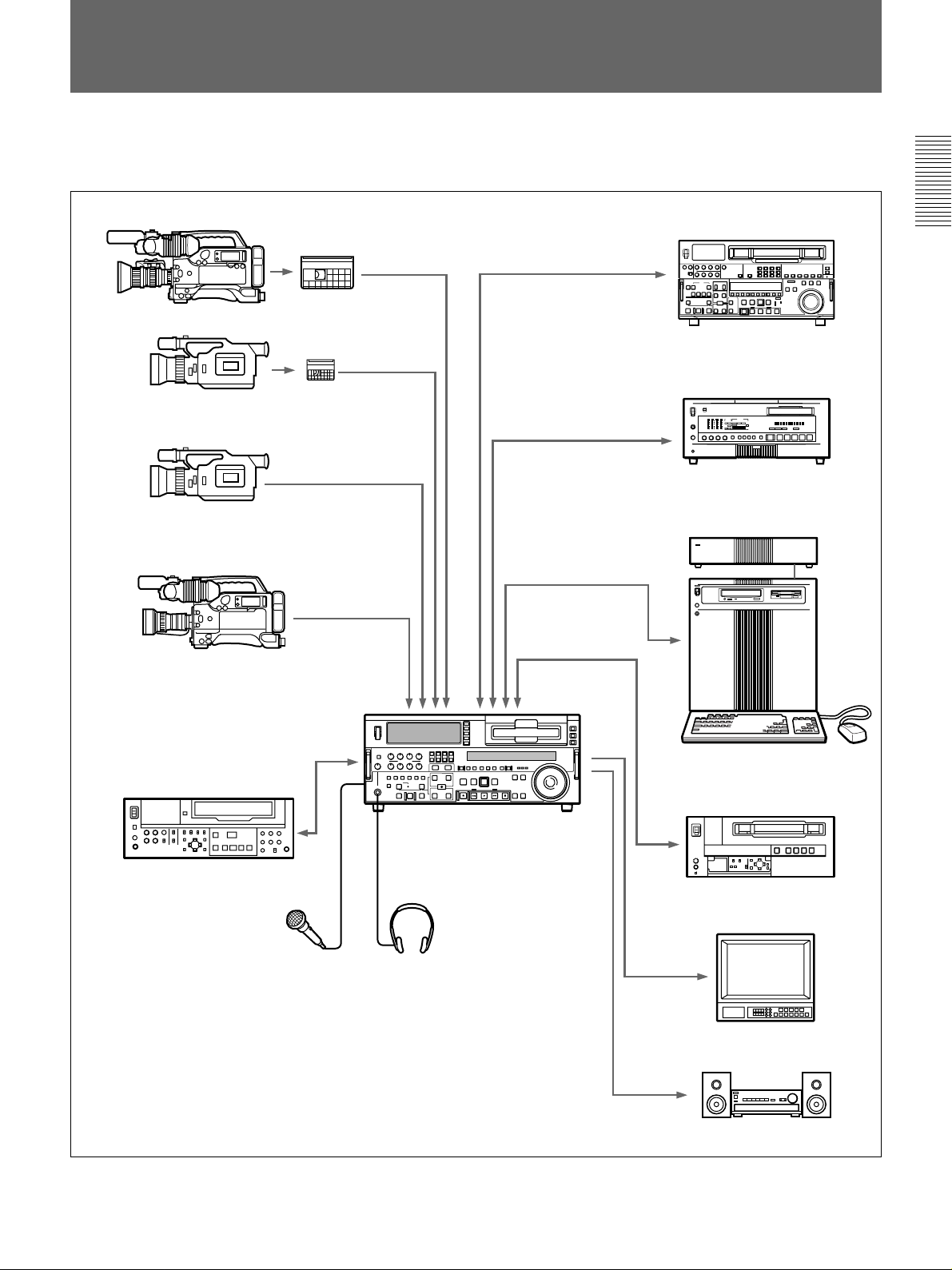
The figure below shows example equipment that can
be connected to this unit.
Chapter 1 Overview
DVCAM camcorder
DV camcorder
DV camcorder
DSR-500WS/500WSP
DVCAM cassette
DV cassette
DNW-A75/A75P
DSR-60/60P/80/80P/85/85P
Digital VCR
ES-7/ES-3 Edit Station
SVO-5800/5800P
Microphone
a) The DSBK-190 is an optional board.
DSR-2000/2000P (this unit)
Headphones
Analog Betacam VCR
Video monitor
Audio monitor system
Chapter 1 Overview 11
Page 12
Location and Function of Parts
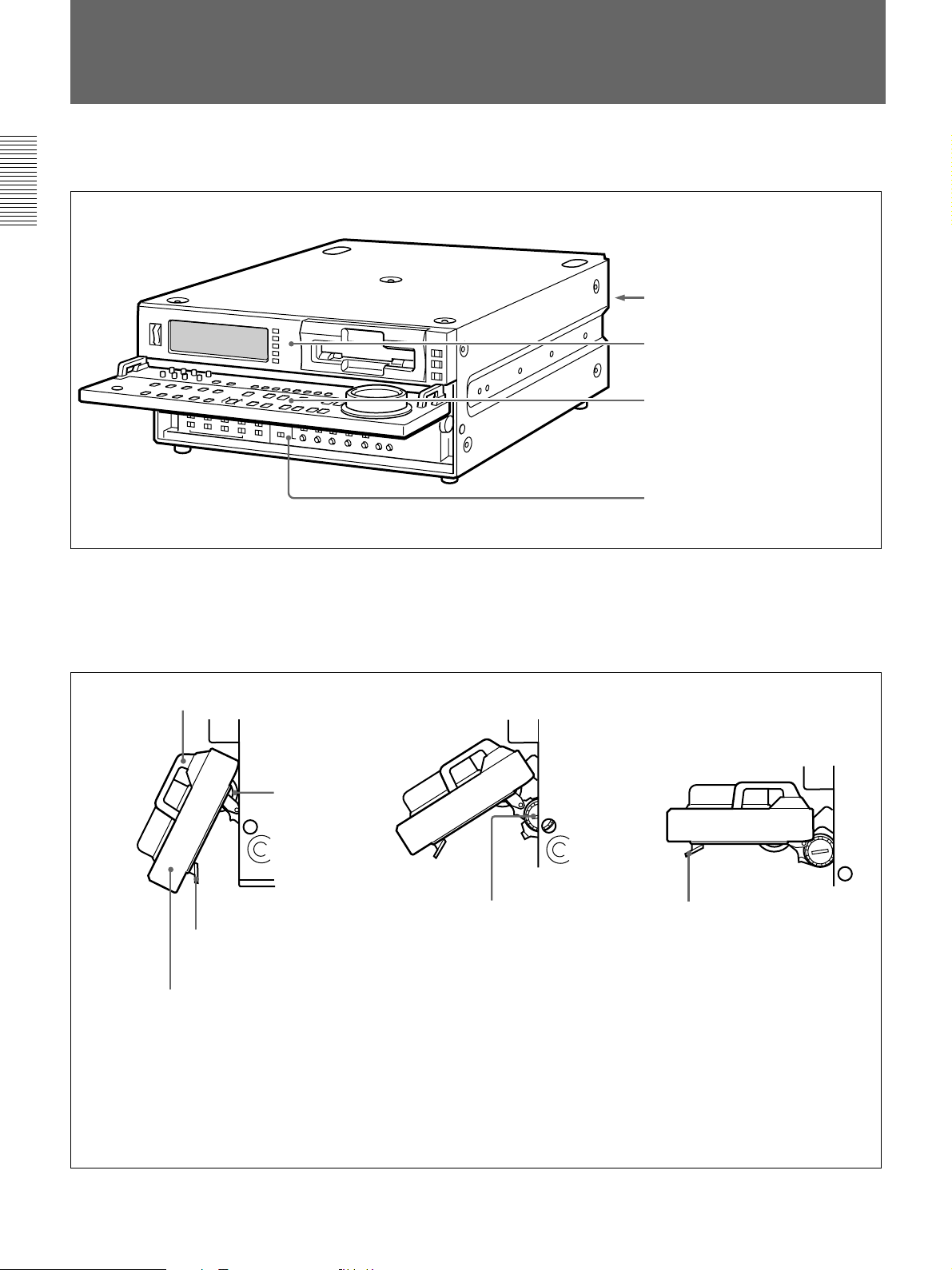
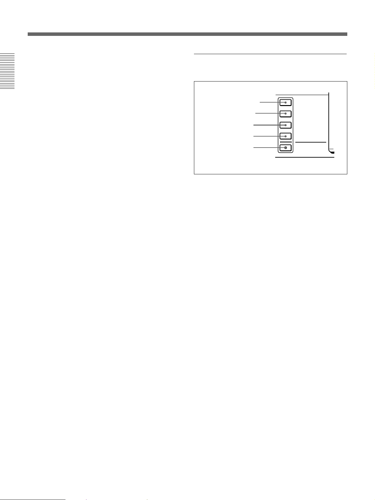
Location and Function of Parts
There are four control panels as shown in the figure
below.
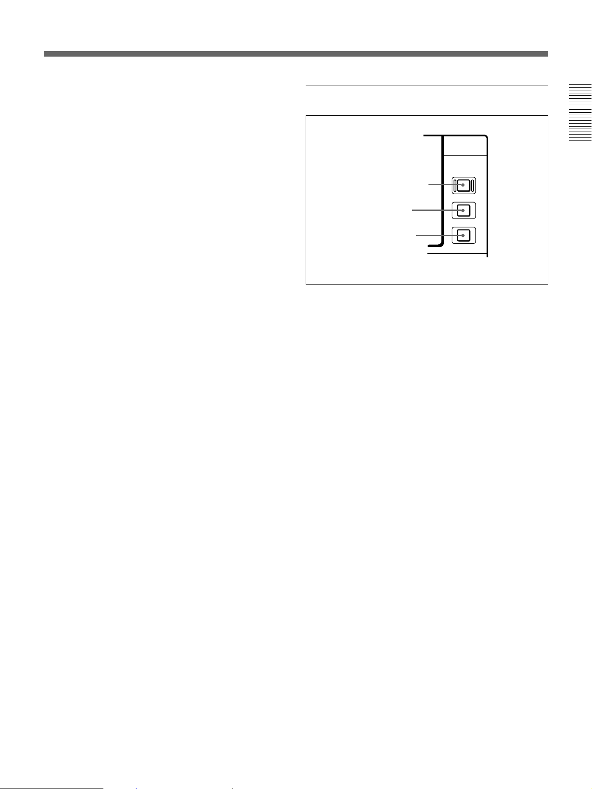
Chapter 1 Overview
To adjust the position of the lower control
panel
You can fix the lower control panel in any position
between vertical and horizontal for ease of operation.
Handle
Connector panel
Upper control panel
Lower control panel
Subsidiary control panel
If you raise the panel to the horizontal, it
automatically locks in position.
(See page 28.)
(See page 13.)
(See page 16.)
(See page 25.)
Lock knob
When the panel is at the desired angle,
turn both lock knobs to fix in position.
Release lever
Raise the panel by holding both ends or
both handles.
To lower the panel, press both
release levers.
To fix the panel at an angle where the lock knobs are inaccessible
1 First position the panel at the desired angle, then without tightening the lock knobs, press the release levers
and raise the panel to the horizontal.
2 With the panel horizontal, tighten the lock knobs, then press the release levers and return the panel to the
desired position, where it will lock into place.
12 Chapter 1 Overview
Page 13
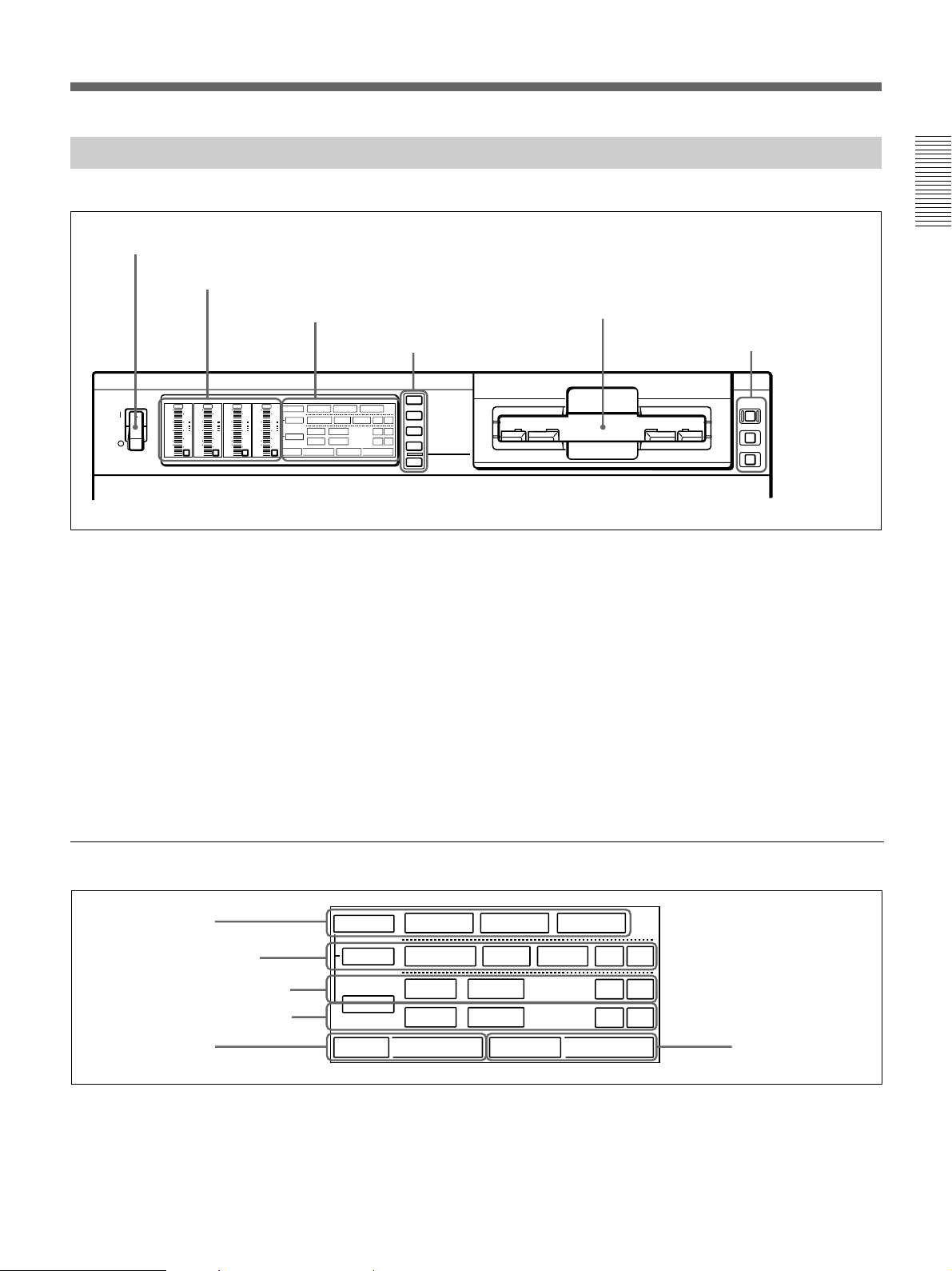
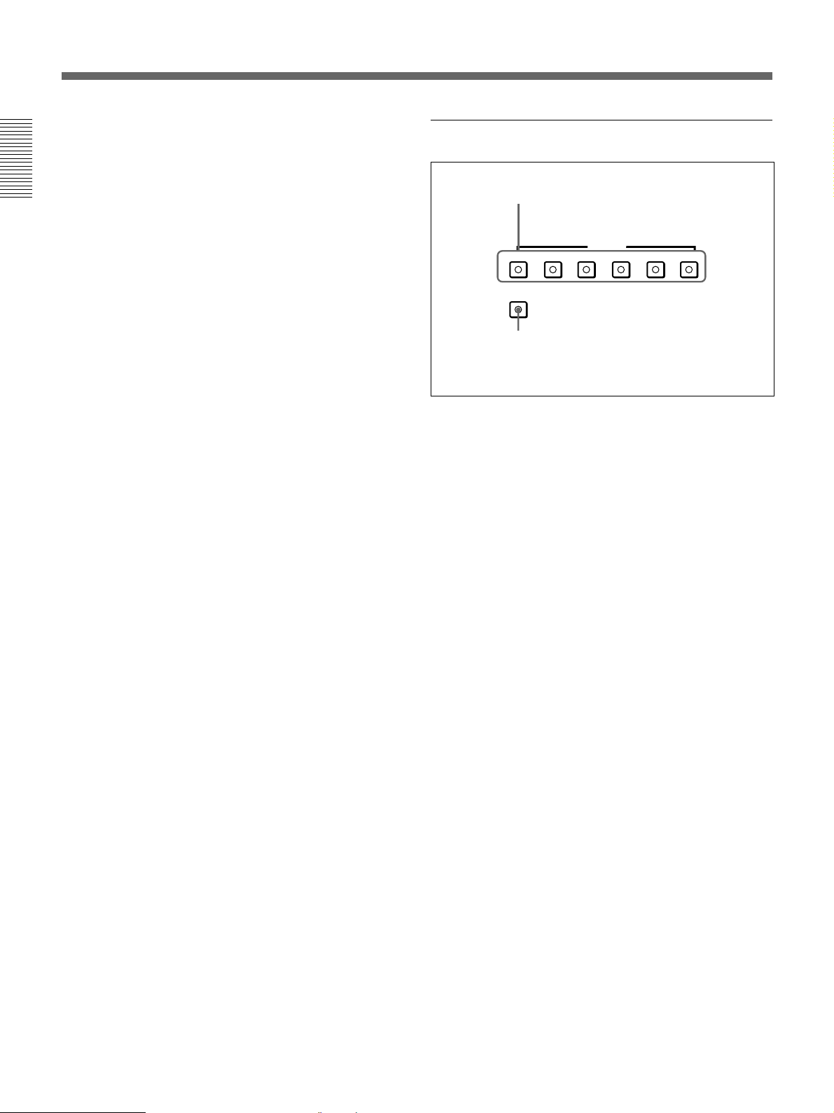
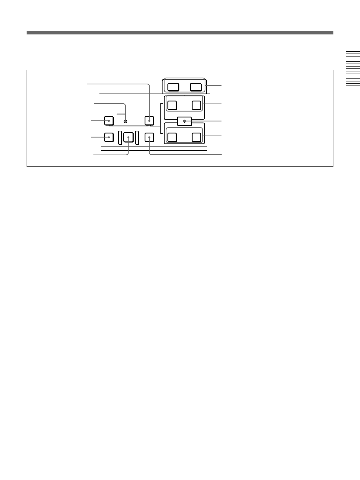
Upper Control Panel
1 POWER switch
2 Audio level meters
1 Input selection/audio mode display section
(see below)
2 Input selection section
(see page 14)
INPUT SELECT
POWER
OVER
OVER
OVER
dB
dB
dB
dB
0
0
2
2
1
-12
-20
-30
-40
-60
1
-12
0
0
-20
-1
-1
-30
-40
-2
-2
-60
1
2
OVER
dB
dB
dB
dB
V:SDTI
SDTI
0
-12
-20
-30
-40
-60
INPUT
0
2
2
VIDEO
1
-12
0
-20
-1
-30
-40
-2
-60
3
COMPOSITE
1
CH11/2
0
ANALOG
AUDIO
-1
ANALOG
CH23/4
-2
PB FS
48k44.1k32k
4
Y-R,B
AES/EBU
AES/EBU
REC MODE
S VIDEO
i.LINK
2CH4CH
SDI SG
SDI SG
SDI SG
SDTI/i.LINK
VIDEO IN
CH-1,1/2
CH-2,3/4
MIXING
1 POWER switch
Press the “1” side to power the unit on. When the unit
is powered on, the display windows in the upper and
lower control panels light.
To power the unit off, press the “¬”side of the switch.
2 Audio level meters
These show the audio levels of channels 1 to 4
1)
(recording levels in recording mode or E-E mode
and
playback level in playback mode).
There are two modes for audio level indications:
FULL and FINE, selected by the METER FULL/FINE
button on the lower control panel.
Chapter 1 Overview
3 Cassette compartment
3 Remote control
setting section
(see page 15)
REMOTE
9PIN
i.LINK
3 Cassette compartment
Accepts DVCAM, DV and DVCPRO(25)
videocassettes.
For details of usable cassettes, see page 33.
1 Input selection/audio mode display section
1 INPUT display
2 INPUT VIDEO display
3 AUDIO CH1, CH1/2 display
4 AUDIO CH2, CH3/4 display
5 PB FS display
INPUT
VIDEO
CH11/2
AUDIO
CH23/4
PB FS
.........................................................................................................................................................................................
1) E-E mode: Abbreviation of “Electric-to-Electric mode”.
In this mode, video and audio signals input to the VCR
are output after passing through internal electric circuits,
V:SDTI
COMPOSITE
ANALOG
ANALOG
48k44.1k32k
SDTI
Y-R,B
AES/EBU
AES/EBU
REC MODE
i.LINK
S VIDEO
2CH4CH
SDI SG
SDI SG
SDI SG
6 REC MODE display
but not through magnetic conversion circuits such as
heads and tapes. This can be used to check input signals
and for adjusting input signal levels.
Chapter 1 Overview 13
Page 14
Location and Function of Parts
1 INPUT display
Indicates the input signal selected with the SDTI/
i.LINK button in the input selection section.
V:SDTI: Digital video signal in SDTI(QSDI) format
Chapter 1 Overview
SDTI: Digital video and audio signals in
SDTI(QSDI) format
i.LINK: Digital video and audio signals in DV
format, using i.LINK technology
2 INPUT VIDEO display
Indicates the input video signal selected with the
VIDEO IN button in the input selection section.
COMPOSITE: Composite video signal
Y-R, B: Y, R−Y and B−Y component video signals
S VIDEO: S-video signal
SDI: SDI video signal
SG: Video test signal
3 AUDIO CH1, CH1/2 display
Indicates the input audio signal selected with the CH1,
CH1/2 button in the input selection section.
ANALOG: Analog audio signal
AES/EBU: Digital audio signal in AES/EBU format
SDI: SDI audio signal
SG: Audio test signal
4 AUDIO CH2, CH3/4 display
Indicates the input audio signal selected with the CH2,
CH3/4 button in the input selection section. The
indications available are the same as for the AUDIO
CH1, CH1/2 display described above.
5 PB FS (playback audio sampling frequency)
display
Indicates the sampling frequency (48 kHz, 44.1 kHz or
32 kHz) at which audio is recorded on tape.
6 REC MODE (audio recording mode) display
Indicates the audio recording mode (2CH or 4CH)
selected with extended menu item 817.
2 Input selection section
1 SDTI/i.LINK button
2 VIDEO IN button
3 CH1, 1/2 button
4 CH2, 3/4 button
5 MIXING button
1 SDTI/i.LINK (SDTI(QSDI) interface/i.LINK
selection) button
Each press of this button cycles through the following
input signal selection options.
•Digital video signal in SDTI(QSDI) format input to
the SDTI(QSDI) INPUT connector
When this is selected, use the CH1, 1/2 button and
CH2, 3/4 button to select the required input audio
signals.
•Digital video and audio signals in SDTI(QSDI)
format input to the SDTI(QSDI) INPUT connector
•Digital video and audio signals in DV format, using
i.LINK technology, input to the i.LINK connector
(available when the optional DSBK-190 i.LINK/DV
Input/Output Board is installed)
In the input selection/audio mode display section, the
INPUT display shows the selection made with this
button.
2 VIDEO IN button
Each press of this button cycles through the following
input video signal selection options.
•Composite video signal input to the VIDEO IN
connectors.
•Component video signals input to the COMPONENT
VIDEO Y/R−Y/B−Y IN connectors
•S-video signal input to the S VIDEO IN connector
•SDI video signal input to the SDI INPUT connector
•Video test signal (selected with extended menu item
710) generated by the internal signal generator
In the input selection/audio mode display section, the
INPUT VIDEO display shows the selection made with
this button.
INPUT SELECT
SDTI/i.LINK
VIDEO IN
CH-1,1/2
CH-2,3/4
MIXING
14 Chapter 1 Overview
Page 15
3 CH1, 1/2 (audio channel 1 or 1/2) button
Each press of this button cycles through the following
input audio signal selection options for audio channel 1
(when in 2-channel mode) or for audio channels 1 and
2 (when in 4-channel mode).
•Analog audio signal(s) input to the AUDIO IN CH-1
connector (when in 2-channel mode) or AUDIO IN
CH-1 and CH-2 connectors (when in 4-channel
mode).
•Digital audio signal in AES/EBU format input to the
DIGITAL AUDIO (AES/EBU) CH-1/2 connector
•SDI audio signal input to the SDI INPUT connector
•Audio test signal (selected with extended menu item
808) generated by the internal signal generator
In the input selection/audio mode display section, the
AUDIO CH1, CH1/2 display shows the selection made
with this button.
4 CH2, 3/4 (audio channel 2 or 3/4) button
Each press of this button cycles through the input audio
signal selection options for audio channel 2 (when in 2channel mode) or for audio channels 3 and 4 (when in
4-channel mode) The input audio signal selection
options corresponding to those for the CH1, 1/2 button
described above are available.
In the input selection/audio mode display section, the
AUDIO CH2, CH3/4 display shows the selection made
with this button.
5 MIXING (mixing setting on/off) button
This enables (ON) or disables (OFF) the setting for
audio input mixing made with extended menu item
819.
3 Remote control setting section
Chapter 1 Overview
REMOTE
1 REMOTE button
9PIN
2 9PIN button
i.LINK
3 i.LINK button
1 REMOTE button
When remote-controlling this unit from the unit
connected to the REMOTE-IN, REMOTE-OUT or
i.LINK connector, press this button, turning it on.
2 9PIN button
When carrying out remote control between this unit
and the unit connected to the REMOTE-IN or
REMOTE-OUT connector, press this button, turning it
on.
3 i.LINK button
When carrying out remote control between this unit
and the unit connected to the i.LINK connector, press
this button, turning it on.
This button is effective only when the optional DSBK190 i.LINK/DV Input/Output Board is installed.
If the selected signal (except for analog audio) is not
supplied to the appropriate connector, the
corresponding indicator in the input selection/audio
mode display section flashes.
Chapter 1 Overview 15
Page 16
Location and Function of Parts
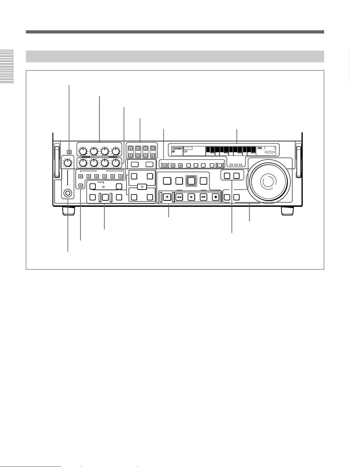
Lower Control Panel
Chapter 1 Overview
1 METER FULL/FINE button
2 REC controls
CH-1
METER
FULL/FINE
PHONE LEVEL
HEADPHONES
CH-2 CH-3 CH-4
REC
PULL FOR VARIABLE
PB
VIDEO
CH-1 CH-2 CH-3 CH-4 TC
ASSEMBLE
DMC EDIT
PREVIEW REVIEW
INSERT
MEMORY
AUTO
EDIT
4 Editing control section
3 Edit mode setting section
3 PB controls
4 MONITOR SELECT buttons
MONITOR SELECT
L
R
LIST MARK
-+
TRIM
IN
DELETE
AUDIO
ENTRY SHIFT
IN OUT
(see page 20)
1 Monitor/menu/display setting
section
(see page 17)
ClipLink
VITC
CH-4CH-3CH-2CH-1
OUT
LP
KEY INHIBIT SERVO
REC
INHIBIT
PREREAD PB/EE PB MENU SET HOLD
REC
PREROLL
STANDBY
EJECT REW PLAY F FWD STOP
5 Tape transport control
section
(see page 22)
(see page 21)
COUNTER
U-BIT TC
HOURS MINUTES SECONDS FRAMES
COUNTER SEL
RESET
EDIT
PLAYERRECORDER
SEARCH VARIABLE
2 Display section
CHANNEL
CONDITION
REPEAT
NOT
EDITABLE
(see page 18)
SHUTTLE
JOG
6 Search control section
(see page 23)
6 PLAYER button and RECORDER button
5 HEADPHONES jack and PHONE LEVEL control
1 METER FULL/FINE button
This switches the display mode of the audio level
meters in the upper control panel as follows:
FULL: In this mode the segment of the display
corresponding to the current audio level and all
lower segments light. A marker indicating the
reference level (set with extended menu item 811)
also appears.
FINE: The display is enlarged, with a step of 0.25 dB
with respect to the reference level of 0 dB.
In this mode only the segment of the display
corresponding to the current audio level lights. If
the audio level exceeds the maximum display
level, the top segment flashes, and if the audio
level goes below the minimum display level, the
bottom segment flashes.
2 REC (recording) controls
These individually adjust the recording levels on
channels 1 to 4.
To set the recording level, put the unit in E-E mode,
pull out the control knobs and adjust the level while
watching the level meters.
When the control knobs are pushed in, the recording
levels return to the preset levels and cannot be
adjusted.
For details of selecting the E-E mode, see the description of
the REC button in the tape transport control section (see
page 22) and the PB/EE button in the monitor/menu/display
setting section (see page 17).
16 Chapter 1 Overview
Page 17

3 PB (playback) controls
These adjust individually the playback levels on
channels 1 to 4.
During playback, pull out the control knobs and adjust
the level while watching the level meters.
When the control knobs are pushed in, the playback
levels return to the preset levels, and cannot be
adjusted.
4 MONITOR SELECT buttons
There are four buttons CH-1 to CH-4 (channels 1 to 4)
in each of the upper (L) and lower (R) rows. Use these
buttons to select the channels for audio output via the
HEADPHONES connector on the lower control panel
and the MONITOR AUDIO connector on the
connector panel.
The HEADPHONES connector outputs stereo sound
(L and R) and the MONITOR AUDIO connector
outputs monaural sound (L and R mixed).
You can select two or more channels in either row by
pressing the buttons for the desired channels
simultaneously. The sounds of the channels selected in
the row are mixed.
In 2-channel audio recording mode (selected with
extended menu item 818), it is possible to use the
AUDIO OUT CH-3 and AUDIO OUT CH-4
connectors for monitor audio output for channels 1 and
2, respectively (use extended menu item 820).
5 HEADPHONES jack and PHONE LEVEL
control
Connect stereo headphones with an impedance of 8
ohms to monitor the sound during recording, playback
and editing.
The PHONE LEVEL control knob adjusts the volume.
6 PLAYER button and RECORDER button
When you carry out editing using a VCR connected to
the REMOTE-IN or REMOTE-OUT connector as the
player and this unit as the recorder, these buttons select
which VCR the editing control buttons and tape
transport buttons on this unit control.
PLAYER: The editing control buttons and tape
transport buttons on this unit control the external
player VCR.
RECORDER: The editing control buttons and tape
transport buttons on this unit control the recorder
(this unit).
When this unit is being used in standalone mode,
neither button functions.
Chapter 1 Overview
1 Monitor/menu/display setting section
PREREAD PB/EE PB MENU SET HOLD
1 PREREAD button
6 PB button
5 PB/EE button
1 PREREAD button
When this is lit, a preread (read-before-write) is carried
out in insert editing.
For details of preread editing, see the section “Preread
Editing” (page 87).
2 MENU button
Use this button for setup menu operations.
Pressing this button, turning it on, shows setup menus
in the time counter display (see page 18).
Press the button once more to exit from the menu
display.
2 MENU button
3 SET button
COUNTER SEL
7 HOLD button
For details of setup menu operations, see Chapter 6 “Setup
Menu” (page 107).
RESET
4 RESET button
8 COUNTER SEL button
3 SET button
Use this button for setting time code and user bit
values and in setup menu operations.
For details of setting time code and user bit values see
Chapter 2 “Setting/Displaying Time Data and Text
Information” (page 35).
Chapter 1 Overview 17
Page 18
Location and Function of Parts
4 RESET button
To reset a time counter value (COUNTER) shown in
the time counter display, press this button.
Resetting the COUNTER value erases all edit points.
This button is also used for setting time code and user
Chapter 1 Overview
bit values and in setup menu operations.
5 PB/EE (playback/E-E) button
To select E-E mode input signals for the video/audio
signals output during fast forward, rewind, still, and
standby, press this button, turning it on.
Either one of this button and the PB button is always
lit.
6 PB (playback) button
To select playback signals for the video/audio signals
output during fast forward, rewind, still, and standby,
press this button, turning it on.
Either one of this button and the PB/EE button is
always lit.
7 HOLD button
To stop updating of the time code or user bit value in
the time counter display (that is, to hold the display),
press this button, turning it on. To set a time code or
user bit value, first press this button to hold the value.
8 COUNTER SEL (select) button
This switches the value shown in the time counter
display in the following sequence: COUNTER, TC, UBIT.
Time counter display selection
Selection Value displayed
COUNTER Tape running time (hours, minutes,
TC
U-BIT User bit value inserted in the playback time
a) The selection of TC or VITC is made by the TC SELECT
switch on the subsidiary control panel.
seconds, frames)
Playback time code read by the internal
time code reader or time code being
recorded.
code or time code being recorded.
a)
a)
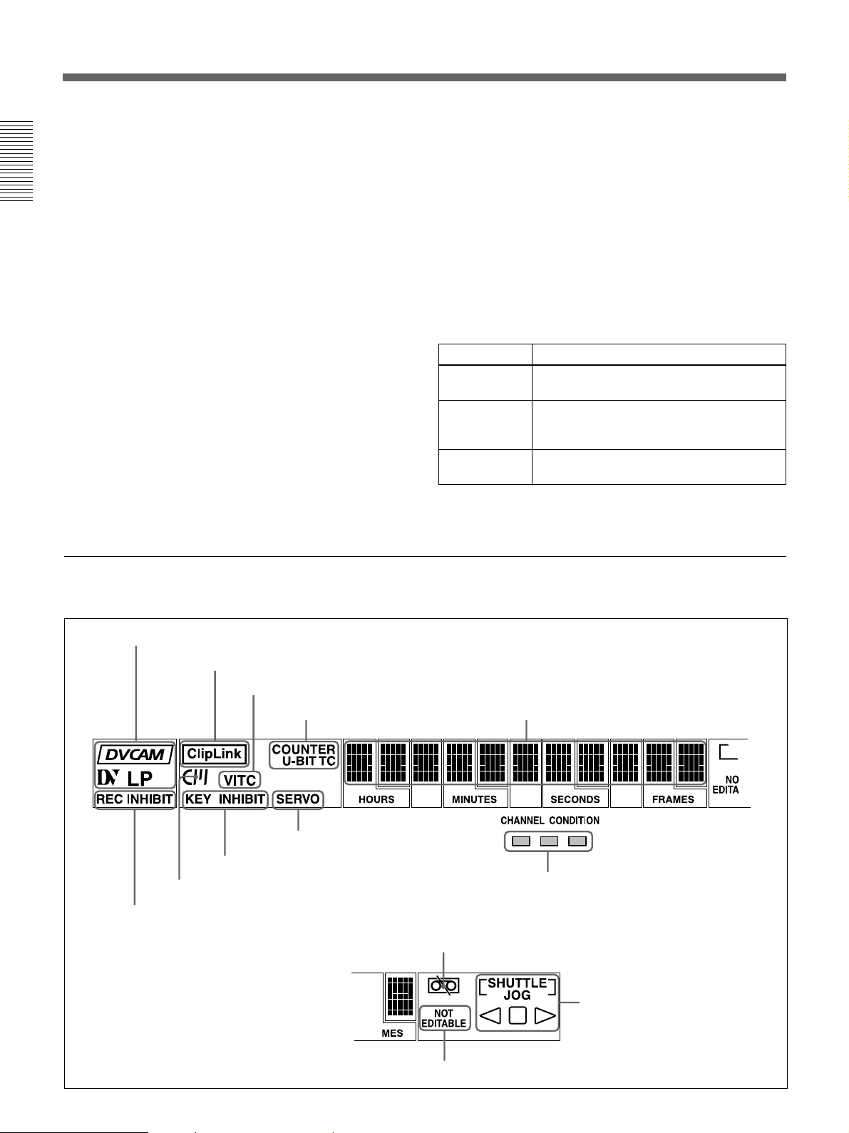
2 Display section
1 Recording/playback format indicators
7 Cassette memory indicator
6 REC INHIBIT indicator
2 ClipLink indicator
3 VITC indicator
4 Time data type indicators
9 SERVO indicator
8 KEY INHIBIT indicator
5 Time counter display
!º CHANNEL CONDITION indicator
!¡Tape end alarm indicator
18 Chapter 1 Overview
!™ SHUTTLE/JOG indicators
!£ NOT EDITABLE indicator
Page 19

1 Recording/playback format indicators
DVCAM: This lights when a tape recorded in
DVCAM format is played back.
DV: This lights when a tape recorded in consumer
DV format is played back.
LP: This lights when a tape recorded in LP mode is
played back.
When a tape recorded in DVCPRO (25) format or any
other format than those mentioned above is played
back, none of the above indicators lights.
2 ClipLink indicator
Lights when a cassette is loaded on which ClipLink
log data is stored in the cassette memory.
For details of ClipLink log data, see the appendix “ClipLink
Guide” (page 147).
6 REC (recording) INHIBIT indicator
This indicator is on or off according to the
combination of the setting of the REC INHIBIT switch
on the subsidiary control panel and the REC/SAVE
switch on the loaded cassette, as shown in the
following table. When this indicator is on, recording
on tape is prohibited.
REC INHIBIT indicator indications
REC INHIBIT
switch position
ON SAVE/REC Lit
OFF SAVE Lit
a) It is possible to make a setting (extended menu item 107)
so that in this case the indicator flashes.
State of the REC/
SAVE switch on
the cassette
REC Off
REC INHIBIT
indicator state
a)
Chapter 1 Overview
3 VITC indicator
Lights when VITC is being read or recorded regardless
of the data shown in the time counter display.
4 Time data type indicators
One of the three indicators (COUNTER, U-BIT, and
TC) lights to indicate the type of time data currently
shown in the time counter display.
COUNTER: Count value of the time counter
U-BIT: User bit data
TC: SMPTE time code (DSR-2000) or EBU time
code (DSR-2000P)
5 Time counter display
Indicates the count value of the time counter, time
code, or user bit data depending on the settings of the
COUNTER SEL button in the monitor/menu/display
setting section and the TC SELECT switch on the
subsidiary control panel.
Also used to display edit point values, edit duration
values, error messages and setup menu data.
7 Cassette memory indicator
Lights when a cassette provided with a memory chip
(“cassette memory”) is loaded.
8 KEY INHIBIT indicator
This indicator lights when the KEY INHIBIT switch
on the subsidiary control panel is set to ON.
The buttons/switches to be operable even when this
indicator is on can be determined using extended menu
item 118.
9 SERVO indicator
1)
When the drum servo and capstan servo are locked
,
this indicator lights.
!º CHANNEL CONDITION indicator
This three-color indicator shows the state of the
playback signal.
Green: The state of the playback signal is good.
Yellow: The playback signal is somewhat
deteriorated, but playback is possible.
Red: The playback signal is deteriorated.
When the red indicator remains on, head cleaning
or an internal inspection is necessary.
.........................................................................................................................................................................................
1) Servo lock: This refers to the synchronization of the
phase of the drum rotation and the reference signal for the
tape transport position, so that the video heads can trace
the same pattern on the tape for playback or recording.
Chapter 1 Overview 19
Page 20
Location and Function of Parts
!¡ Tape end alarm indicator
Starts flashing when the remaining capacity of the tape
is for about 2 minutes.
!™ SHUTTLE/JOG indicators
Chapter 1 Overview
When searching in shuttle or variable mode using the
search dial, the SHUTTLE indicator lights, and when
searching in jog mode using the search dial, the JOG
indicator lights. When the search dial is turned
clockwise causing playback to take place in the
forward direction, the · indicator lights. When the
search dial is turned counterclockwise causing
playback to take place in the reverse direction, the ª
indicator lights. When the tape is stopped, the π
indicator lights.
For more information about the search dial, see page 23.
!£ NOT EDITABLE indicator
Lights during playback of a tape that contains a
recording in other than the DVCAM format. When
this indicator is lit, the recordings contained in the tape
can be used as source material for editing, but editing
operations such as insert editing and assemble editing
cannot be performed.
This indicator also lights when the audio recording
mode selected on this unit does not coincides with that
of the loaded tape.
3 Edit mode setting section
1 INSERT buttons
VIDEO
CH-1 CH-2 CH-3 CH-4 TC
ASSEMBLE
2 ASSEMBLE button
1 INSERT buttons
Use these buttons to select the signals for insert
1)
editing
.
VIDEO: To select the video signal, press this button,
turning it on.
CH-1 to CH-4 (channel 1 to channel 4): To select
audio channels 1 to 4, press these buttons, turning
them on. You can select any number of the
channels.
TC: To select time code, press this button, turning it
on.
INSERT
2 ASSEMBLE button
Press this button, turning it on, to carry out assemble
2)
editing
.
All signals (video signals, audio signals, time code
signals, and so forth) are recorded together.
.........................................................................................................................................................................................
1) Insert editing: Editing in which new video/audio is added
into the middle of existing recorded video/audio.
2) Assemble editing: Editing in which new video/audio is
added in sequence to the end of existing recorded video/
audio.
20 Chapter 1 Overview
Page 21
4 Editing control section
1 DELETE button
2 MOMORY indicator
3 DMC EDIT button
4 PREVIEW button
5 AUTO EDIT button
DMC EDIT
MEMORY
AUTO
PREVIEW REVIEW
DELETE
EDIT
-+
1 DELETE button
This deletes an existing edit point.
Hold down this button and press the IN, OUT, AUDIO
IN, or AUDIO OUT button which is lit, indicating an
existing edit point. The button either goes off or
flashes and the corresponding edit point is deleted.
When the button flashes, it is necessary to set the
deleted edit point again.
2 MEMORY indicator
When memorizing the playback speed using the DMC
EDIT button, this indicator flashes as the playback
speed is captured to memory, and lights continuously
once the speed is captured.
3 DMC EDIT button
Use this button to memorize the playback speed varied
between ±1 times normal speed and carry out
automatic playback or automatic editing using the
memorized playback speed.
For information about how to carry out DMC playback or
DMC editing using this button, see the section “Dynamic
Motion Control (DMC) Playback” (page 55) and “DMC
Editing” (page 84), respectively.
4 PREVIEW button
After setting edit points, to preview the editing results
before carrying out the edit, press this button, turning it
on.
If the IN point is not set, the preview is carried out
with the point where you pressed this button as the IN
point.
During the preview the button is lit, and when the
preview ends it flashes.
LIST MARK
TRIM
IN
ENTRY SHIFT
IN OUT
OUT
AUDIO
6 TRIM buttons
7 AUDIO IN button and AUDIO OUT button
8 ENTRY/SHIFT button
9 IN button and OUT button
!º REVIEW button
5 AUTO (automatic) EDIT button
After setting edit points, to carry out automatic editing
(recording), press this button, turning it on.
If the IN point is not set, the automatic editing is
carried out with the point where you pressed this
button as the IN point.
If you pressed the PREVIEW button to carry out a
preview, when the preview ends this button flashes.
6 TRIM buttons
Use these buttons to trim an edit point to single-frame
precision.
Hold down the IN, OUT, AUDIO IN, or AUDIO OUT
button, and press one of these buttons. The MARK/+
button advances the corresponding edit point by one
frame, and the LIST/− button sets it back by one
frame.
During playback, pressing one of these buttons while
holding down the PLAY button adjusts the tape speed
by +8% or −8%, correspondingly. (Capstan override
function)
These buttons are also used for ClipLink operations
and setup menu operations.
For more information about ClipLink operations and setup
menu operations, see Chapter 5 “ClipLink Operation”
(page 97) and Chapter 6 “Setup Menu” (page 107),
respectively.
7 AUDIO IN button and AUDIO OUT button
In insert editing, to set an audio IN point or audio OUT
point separate from the corresponding video edit point,
hold down the AUDIO IN button or AUDIO OUT
button, and press the ENTRY/SHIFT button.
After you have made the setting, pressing the AUDIO
IN button or AUDIO OUT button displays the audio
IN point or audio OUT point set on the time counter
display.
Chapter 1 Overview 21
Chapter 1 Overview
Page 22

Location and Function of Parts
8 ENTRY/SHIFT button
Use this button for setting edit points, carrying out
ClipLink operations, and so forth.
•To set a video IN point or OUT point: Hold down the
Chapter 1 Overview
IN button or OUT button, and press this button.
•To set an audio IN point or OUT point: Hold down
the AUDIO IN button or AUDIO OUT button, and
press this button.
For more information about ClipLink operation, see
Chapter 5 “ClipLink Operation” (page 97).
9 IN button and OUT button
To set a video IN point or OUT point, hold down the
IN button or OUT button, and press the ENTRY/
SHIFT button.
After you have made the setting, pressing the IN
button or OUT button displays the IN point or OUT
point on the time counter display.
!º REVIEW button
Use this button to carry out a review of the editing
results after carrying out automatic editing.
5 Tape transport control section
1 STANDBY button
When a cassette is inserted and this button is off, to put
the VCR in standby mode, press the button, turning it
on.
In standby mode, the drum is rotating and the tape is in
contact with the drum. As a result, recording or
playback can start immediately.
To end standby mode, press the STANDBY button,
turning it off.
If eight minutes (value can be varied using extended
menu item 501) elapse in standby mode, the unit
automatically switches out of standby mode to protect
the tape.
2 PREROLL button
Press this button to cue up to the preroll point (before
the IN point by the time set as the preroll time) on the
tape. You can change or select the preroll time and the
1)
state of the unit at the end of preroll (stop mode
or
still playback mode) using basic menu item 001 and
extended menu item 401.
Cuing up to edit points
Hold down the IN, OUT, AUDIO IN, or AUDIO OUT
button while pressing this button to cue up to the
corresponding edit point.
1 STANDBY button
3 REC (record) button
To start recording, press this button together with the
2 PREROLL button
3 REC button
STANDBY
PREROLL
EJECT REW PLAY F FWD STOP
REC
4 EDIT button
EDIT
5 STOP button
PLAY button, turning it on.
Monitoring in E-E mode
When the unit is in stop mode, pressing this button
lights it, and you can monitor the video and audio in EE mode. To return to the original state, press the STOP
button.
During playback, search, fast forward, or rewind,
holding down this button allows you to monitor the
9 F FWD button
8 PLAY button
7 REW button
6 EJECT button
video and audio in E-E mode. In this case the button
does not light.
.........................................................................................................................................................................................
1) Stop mode: the state in which the device currently the
subject of operation is stopped, and the STOP button is
lit.
22 Chapter 1 Overview
Page 23
4 EDIT button
To carry out manual editing, press this button
simultaneously with the PLAY button.
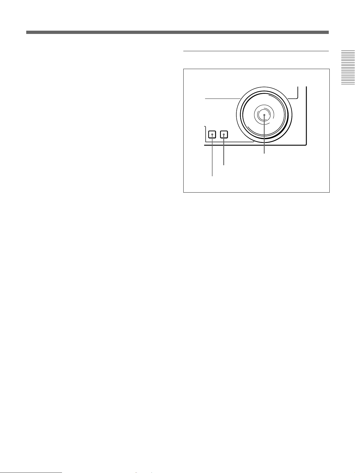
6 Search control section
Monitoring in E-E mode
When the unit is in stop mode, pressing this button
lights it, and you can monitor the input signal selected
with the ASSEMBLE button or INSERT buttons in EE mode. To return to the original state, press the STOP
button. During playback, search, fast forward, or
rewind, holding down this button allows you to
monitor the video in E-E mode.
5 STOP button
To stop recording or playback, press this button,
turning it on.
When you stop playback, the unit switches either to
still playback or to E-E mode according to setup menu
settings, and the settings of the PB/EE button and PB
button.
Fault display function
This button flashes when there is no external reference
signal input or the input external reference signal is not
synchronized to the input video signal.
6 EJECT button
To eject the cassette, press this button. While the
cassette is being ejected, this button lights.
7 REW (rewind) button
To rewind the tape, press this button, turning it on.
Chapter 1 Overview
SEARCH VARIABLE
3 Search dial
2 VARIABLE button
1 SEARCH button
1 SEARCH button
To use the search dial for playback in shuttle or jog
mode, press this button, turning it on. Pressing the dial
toggles between shuttle and jog modes. In shuttle
mode, the SHUTTLE indicator in the display section
lights, and in jog mode, the JOG indicator in the
display section lights.
2 VARIABLE button
To use the search dial for playback in variable speed
mode, press this button, turning it on. Pressing the dial
toggles between variable speed mode and jog mode.
8 PLAY button
To start playback, press this button, turning it on.
To operate in capstan override mode
Hold down this button, and turn the search dial.
For details of capstan override mode, see “3 Search dial”
on this page.
9 F FWD (fast forward) button
To fast forward the tape, press this button, turning it
on.
3 Search dial
Turn this to carry out playback in the modes shown in
the following table. Turning the dial clockwise lights
the · indicator in the display section and plays back
in the forward direction. Turning the dial
counterclockwise lights the ª indicator in the display
section and plays back in the reverse direction. When
the tape is stopped, the π indicator in the display
section lights.
Pressing this dial toggles between shuttle mode and
jog mode (or between variable mode and jog mode).
When playing back in shuttle or variable mode, the
SHUTTLE indicator in the display section lights, and
when playing back in jog mode, the JOG indicator
lights.
You can carry out noiseless playback in the range of ±
1 times normal speed.
Chapter 1 Overview 23
Page 24

Location and Function of Parts
Playback modes using the search dial
Playback
mode
Shuttle Press the SHUTTLE button or the search dial
Chapter 1 Overview
Jog
Variable
speed
Capstan
override
Operations and functions
so that the SHUTTLE indicator in the display
section lights, then turn the search dial.
Playback is carried out at a speed determined
by the position of the search dial. The
maximum shuttle mode playback speed can be
changed using extended menu item 102.
Press the SHUTTLE button or the search dial
so that the JOG indicator in the display section
lights, then turn the search dial. Playback is
carried out at a speed determined by the speed
of rotation of the search dial. The playback
speed range is ±1 times normal speed. The
search dial has no detents.
Press the VARIABLE button, turning it on, then
turn the search dial. You can control the
playback speed finely (61 steps) in the range of
–1 to +2 times normal speed.
The search dial has detents at the still position
and at the normal speed position.
The variable mode playback speed range can
be changed using extended menu item 119.
Noiseless playback is possible in the range of
±1 times normal speed.
Hold down the PLAY button and turn the
search dial to adjust the playback speed in the
range of ±15%. Use this for phase adjustment
between this unit and an external device
connected to this unit.
Changing the setting of extended menu item 101 enables you
to select shuttle or jog mode just by turning the search dial
without using the SEARCH or VARIABLE button.
24 Chapter 1 Overview
Page 25
Subsidiary Control Panel
1 CHARACTER switch
2 CONTROL PANEL switch
3 REC INHIBIT switch
EXT INT
REGEN PRESET
CHARACTER
OFF ON
REC FREE
RUN RUN
CONTROL PANEL
EXT INT
NDF DF
TC GENERATOR
REC INHIBIT
ON OFF
OFF ON
VITC
9 VITC switch
8 DF/NDF switch (DSR-2000 only)
7 FREE RUN/REC RUN switch
6 INT/EXT−PRESET/REGEN switch
!™ SET UP (DSR-2000)/BLACK LEVEL (DSR-2000P)
knob and PRESET/MANUAL switch
!£ CHROMA knob and PRESET/MANUAL switch
4 KEY INHIBIT switch
5 PROCESS CONTROL switch
KEY INHIBIT
ON OFF
VITC TC
TC SELECT
CONTROL
REMOTE LOCAL
MENU
PRESET
VIDEO
MANUAL
PRESET
CHROMA
MANUAL
PRESET
MANUAL
SET UP
PROCESS
!º TC SELECT switch !¡ VIDEO knob and PRESET/MANUAL switch
!¢ Y/C DELAY knob and PRESET/MANUAL switch
!∞ CHROMA PHASE (HUE) (DSR-2000)/
CHROMA PHASE (DSR-2000P) knob and
PRESET/MANUAL switch
Chapter 1 Overview
PRESET
VIDEO
MANUAL
PRESET
CHROMA
PRESET
MANUAL
1 CHARACTER switch
Select whether or not to superimpose text information
such as time code, menu settings, and alarm messages
on the video signal output from the SDI OUTPUT 3
(SUPER) connector and VIDEO OUT 3 (SUPER)
connector.
ON: Superimposed text
OFF: No superimposed text
The factory default setting is ON.
PRESET
MANUAL
MANUAL
PRESET
MANUAL
!§ SYNC knob
!¶ SC knob
SET UP
Y/C DELAY
CHROMA PHASE
(HUE)
SYSTEM PHASE
SYNC
SC
2 CONTROL PANEL switch
Select the state of the control panel when this unit is
operated.
INT: When operating this unit by its own control
panel.
EXT: When operating this unit remotely by the
optional DSBK-200 Control Panel connected to
the CONTROL PANEL connector.
The factory default setting is INT.
Chapter 1 Overview 25
Page 26
Location and Function of Parts
3 REC (record) INHIBIT switch
When this switch is set to ON, the REC INHIBIT
indicator in the display section lights, and recording on
tape is no longer possible.
Chapter 1 Overview
4 KEY INHIBIT switch
When this switch is set to ON, the KEY INHIBIT
indicator in the display section lights, and the buttons
in the upper control panel and lower control panel
specified by the setting of extended menu item 118 are
disabled.
5 PROCESS CONTROL switch
This selects the method of control of the internal
digital video processor.
REMOTE: Select this position to use an optional
UVR-60/60P or BVR-50/50P Remote Control
Unit for remote control of the internal digital
video processor.
MENU: Select this position to use the setup menu to
change the settings for the internal digital video
processor.
LOCAL: Select this position to use the subsidiary
control panel to change the settings for the internal
digital video processor.
6 INT/EXT–PRESET/REGEN (internal/external−
preset/regenerated) switch
This switch is used to make selections relating to the
time code and the internal time code generator.
(In this Operating Instructions, this switch may also be
called simply as the INT/EXT switch or PRESET/
REGEN switch depending on the contents of the
description in which the switch is referred to.)
Selection of internal/external time code
Setting
INT
EXT The external time code selected as follows.
Time code used
The time code produced by the internal time
code generator
By setting the switch in the INT/REGEN position
or INT/PRESET position, you can select
“PRESET” or “REGEN” for the internal time
code generator
• When the TC SELECT switch is set to TC
The external time code input to the TIME
CODE IN connector
• When the TC SELECT switch is set to VITC
The VITC time code included in the input
video signal
In this case, for the internal time code generator,
“REGEN” is always selected
.
table)
(see the next table)
(see the next
Selection relating to the internal time code generator
Setting
PRESET The initial value of the time code produced by
REGEN The internal time code generator is
Operation of the internal time code generator
the internal time code generator can be preset
by a control panel operation or by remote control
from a device connected to the REMOTE-IN or
REMOTE-OUT connector.
synchronized to the playback time code read by
the internal time code reader.
7 FREE RUN/REC RUN switch
This switch selects the time code run mode of the
internal time code generator.
FREE RUN: Regardless of the operating mode of
this unit, the time code value advances
continuously while the power is on.
REC RUN: The time code value advances only
during recording. When this mode is selected, set
the INT/EXT−PRESET/REGEN switch to INT−
PRESET.
8 DF/NDF (drop-frame/non-drop-frame) switch
(for the DSR-2000 only)
This switch selects the mode of advancing the time
code generator and time counter.
DF: Drop-frame mode
NDF: Non-drop-frame mode
Note
When the PRESET/REGEN switch is set to REGEN,
since the time code generator is synchronized to the
playback time code, this switch has no effect.
9 VITC switch and indicator
To record the time code produced by the internal time
code generator as a VITC, set this switch to ON.
When this switch is set to OFF, internally generated
time code is not recorded as VITC, but VITC present
in the input video signal is recorded unchanged.
!º TC (time code) SELECT switch
.
This switch selects the time code, TC or VITC, shown
in the time counter display. When VITC is selected,
the VITC indicator in the display section lights.
26 Chapter 1 Overview
Page 27

!¡ VIDEO knob and PRESET/MANUAL switch
The switch makes the selection described below.
When it is set to MANUAL, you can use the knob to
adjust the video signal output level.
PRESET: Regardless of the position of the knob, the
video signal output level is set to the reference
value.
MANUAL: You can adjust the video signal output
level in the range ±3 dB.
You can change the adjustment range using
extended menu item 714.
!™ SET UP (DSR-2000)/BLACK LEVEL (DSR2000P) knob and PRESET/MANUAL switch
The switch makes the selection described below.
When it is set to MANUAL, you can use the knob to
adjust the (black) setup level (DSR-2000) or black
level (DSR-2000P).
PRESET: Regardless of the position of the knob, the
setup level (DSR-2000) or black level (DSR2000P) is set to the reference value.
MANUAL: You can adjust the setup level (DSR-
1)
2000) in the range ±30 IRE
, or the black level
(DSR-2000P) in the range ±210 mV.
!£ CHROMA (chrominance) knob and PRESET/
MANUAL switch
The switch makes the selection described below.
When it is set to MANUAL, you can use the knob to
adjust the chrominance signal output level.
PRESET: Regardless of the position of the knob, the
chrominance signal output level is set to the
reference value.
MANUAL: You can adjust the chrominance signal
output level in the range ±3 dB.
You can change the adjustment range using
extended menu item 714.
!¢ Y/C DELAY knob and PRESET/MANUAL
switch
The switch makes the selection described below.
When it is set to MANUAL, you can use the knob to
adjust the Y/C delay.
PRESET: Regardless of the position of the knob, the
Y/C delay is set to the reference value.
MANUAL: You can adjust the Y/C delay in the
range ±100 ns.
!∞ CHROMA PHASE (HUE) (DSR-2000)/
CHROMA PHASE (DSR-2000P) knob and
PRESET/MANUAL switch
The switch makes the selection described below.
When it is set to MANUAL, you can use the knob to
adjust the hue/chrominance phase (the phase
difference from a burst signal).
PRESET: Regardless of the position of the knob, the
hue/chrominance phase is set to the reference
value.
MANUAL: You can adjust the hue/chrominance
phase in the range ±30°.
!§ SYNC knob
This adjusts the output signal sync phase with respect
to the input reference signal to this unit in the range ±3
µs.
Use this adjustment when the output phase of this unit
is not accurately aligned with the reference signal
phase, or when carrying out special effects editing with
this unit and other VCRs connected to a switcher or
other equipment.
!¶ SC (subcarrier) knob
This adjusts the output signal subcarrier phase with
respect to the input reference signal to this unit in the
range ±180°.
For editing with composite signals, use this adjustment
when the output phase of this unit with respect to the
phase of the reference signal is not accurately aligned
with the subcarrier phase.
Chapter 1 Overview
.........................................................................................................................................................................................
1) IRE: A unit for representing a video level laid down by
the IRE (Institute of Radio Engineers). The IRE is now
the IEEE (Institute of Electrical and Electronic
Engineers).
Chapter 1 Overview 27
Page 28
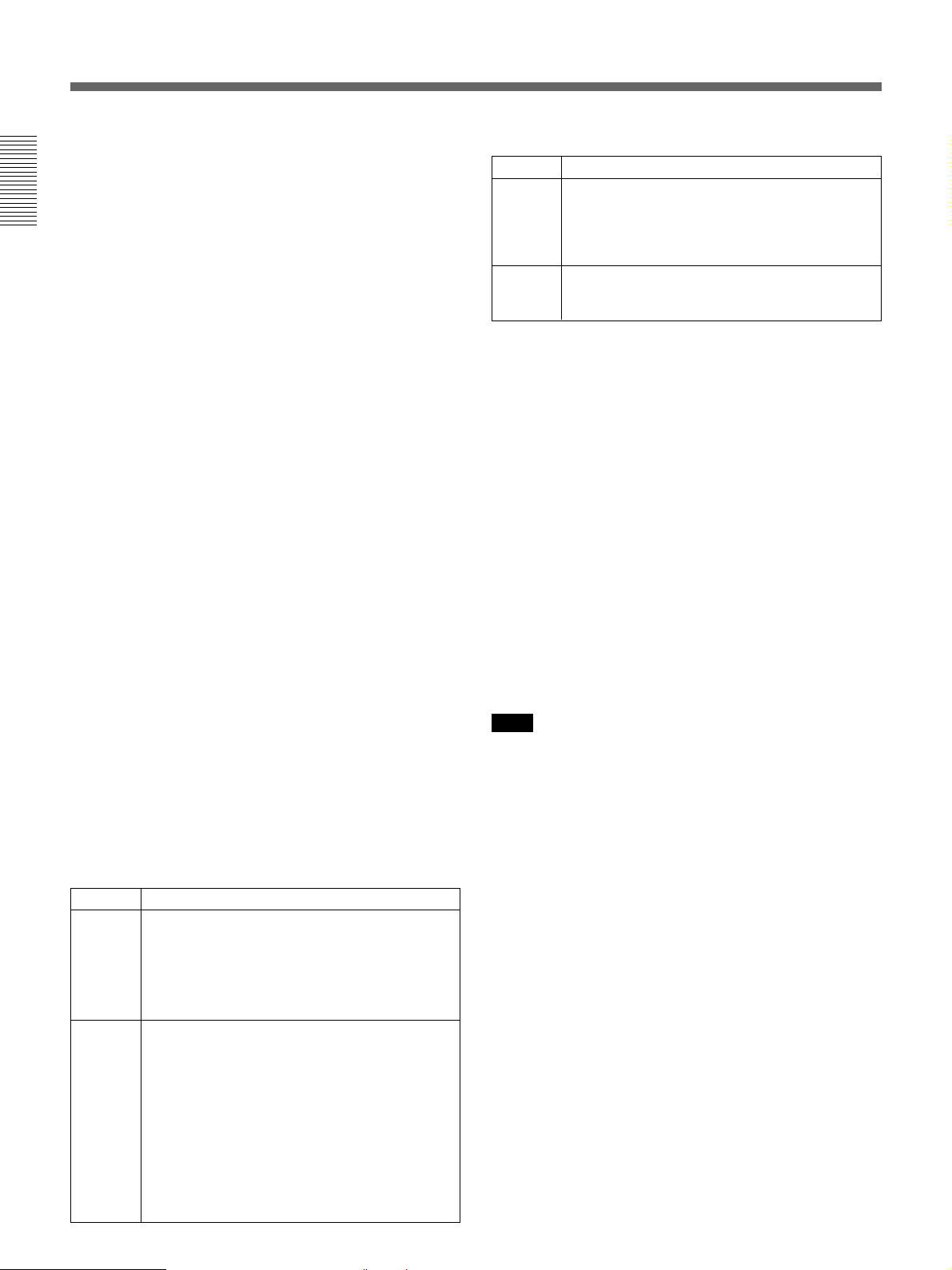
Location and Function of Parts
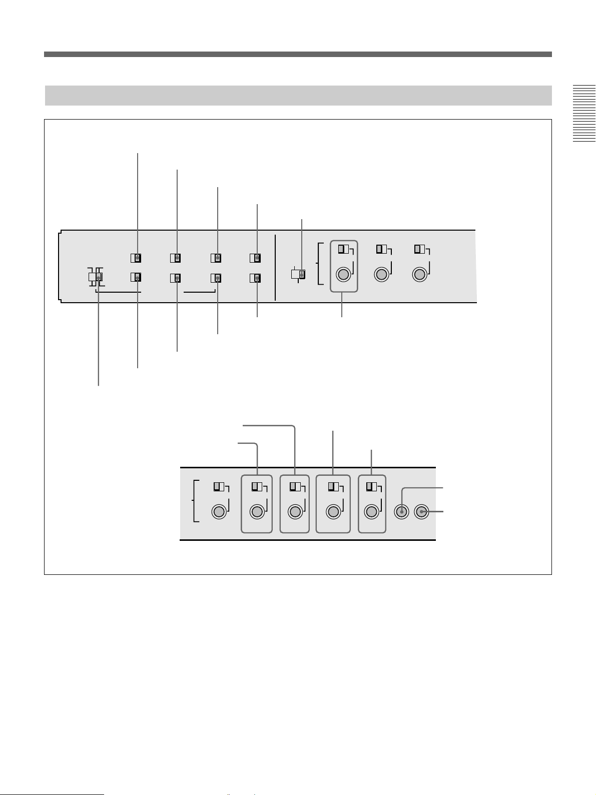
Connector Panel
Chapter 1 Overview
~AC IN
1 AC IN
connector
ANALOG VIDEO I/O DIGITAL AUDIO I/O(AES/EBU) SDTI(QSDI)
REF.VIDEO
VIDEO CONTROL
CONTROL PANEL
REMOTE-IN
REMOTE-OUT
TIME CODE
IN
3 External device connectors
(see page 31)
2 Ground terminal
1 Analog video input/output section
2 Digital input/output section
IN
75Ω
ON
OFF
OUT
IN
OUT
S VIDEO
VIDEO OUT
1
2
3
OUT
VIDEO IN
(SUPER)
75Ω
ON
OFF
CH-1/2
CH-1/2
COMPONENT VIDEO
IN
IN
OUT
OUT
Y
R-Y
B-Y
MONITOR AUDIO
CH-3/4
CH-3/4
INPUT OUTPUT
SDI INPUT SDI OUTPUT
AUDIO IN
OFF
-6dBm +4dBm
CH-1
AUDIO OUT
CH-1
4 Analog audio input/output section
(see page 29)
LEVEL
LEVEL
HIGHLOW
ON
-600
Ω
OFF
0dBm
0dBm
-6dBm +4dBm
CH-2 CH-3
CH-2 CH-3
(see page 30)
i.LINK
123
(SUPER)
LEVEL
0dBm
HIGHLOW
ON
-600
LEVEL
Ω
ON
OFF
0dBm
-6dBm +4dBm
CH-4
CH-4
HIGHLOW
-600
HIGHLOW
ON
-600
Ω
OFF
-6dBm +4dBm
Ω
(see page 31)
This figure shows the connector panel fitted with the optional DSBK-190 i.LINK/DV Input/Output Board.
1 AC IN connector
Use the optional power cord to connect this to an AC
outlet.
2 Ground terminal
Connect this to ground.
28 Chapter 1 Overview
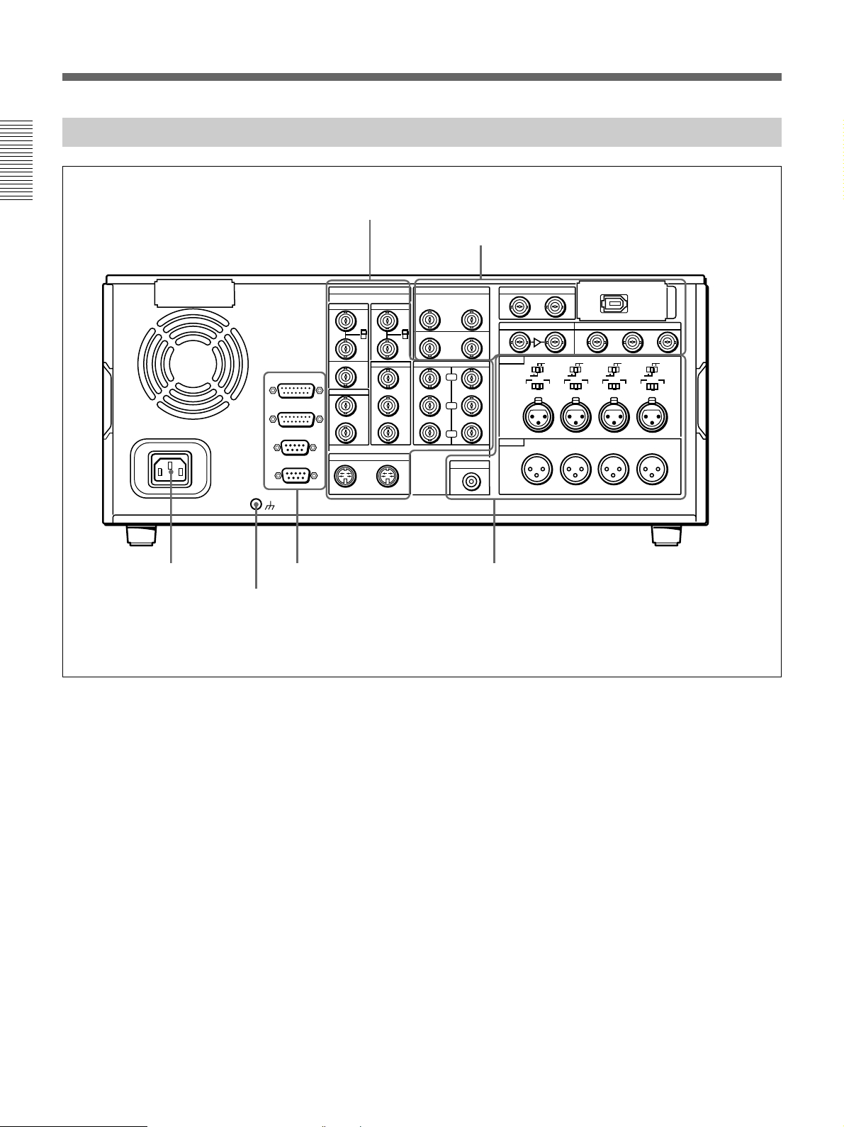
Page 29
1 Analog video input/output section
1 REF. VIDEO IN connectors
and 75Ω termination switch
2 REF. VIDEO OUT connector
3 TIME CODE IN connector
4 TIME CODE OUT connector
5 S VIDEO IN connector
6 S VIDEO OUT connector
ANALOG VIDEO I/O
REF.VIDEO
IN
75Ω
ON
OFF
OUT
TIME CODE
IN
OUT
S VIDEO
IN
VIDEO IN
VIDEO OUT
1
2
3
OUT
75Ω
ON
OFF
(SUPER)
7 VIDEO IN connectors and 75Ω termination
switch
8 COMPONENT VIDEO Y/R−Y/B−Y IN
connectors
COMPONENT VIDEO
IN
OUT
Y
R-Y
B-Y
!º VIDEO OUT 1, 2, and 3 (SUPER) connectors
9 COMPONENT VIDEO Y/R−Y/
B−Y OUT connectors
Chapter 1 Overview
1 REF. (reference) VIDEO IN connectors (BNC
type) and 75Ω termination switch
Input a reference video signal to one of these
connectors. The two connectors can be used for a loopthrough connection. When making a loop-through
connection, set the termination switch to OFF, and
when not, set the switch to ON.
2 REF. (reference) VIDEO OUT connector (BNC
type)
This connector outputs a reference video signal, except
when i.LINK is selected in the input selection section
(see page 14).
3 TIME CODE IN connector (BNC type)
Input SMPTE time code (DSR-2000) or EBU time
code (DSR-2000P) externally generated to this
connector.
4 TIME CODE OUT connector (BNC type)
This connector outputs a time code according to the
operating state of the unit, as follows:
During playback: the playback time code
During recording: the time code generated by the
internal time code generator or the time code input
to the TIME CODE IN connector.
For more information about the time code output during
recording, see extended setup menu item 611.
5 S VIDEO IN connector (4-pin)
Input an S-video signal with separated Y (luminance)
and C (chroma: 3.58 MHz for DSR-2000 or 4.43 MHz
for DSR-2000P) components to this connector.
6 S VIDEO OUT connector (4-pin)
This connector outputs an S-video signal with
separated Y (luminance) and C (chroma: 3.58 MHz for
DSR-2000 or 4.43 MHz for DSR-2000P) components.
7 VIDEO IN connectors (BNC type) and 75W
termination switch
Input an analog composite video signal to one of these
connectors. The two connectors can be used for a loopthrough connection. When making a loop-through
connection, set the 75Ω termination switch to OFF and
when not, set the switch to ON.
Chapter 1 Overview 29
Page 30
Location and Function of Parts
8 COMPONENT VIDEO Y/R–Y/B–Y IN
connectors (BNC type)
Input analog component video signals (Y/R−Y/B−Y)
to these connectors.
Chapter 1 Overview
9 COMPONENT VIDEO Y/R–Y/B–Y OUT
connectors (BNC type)
These connectors output analog component video
signals (Y/R−Y/B−Y).
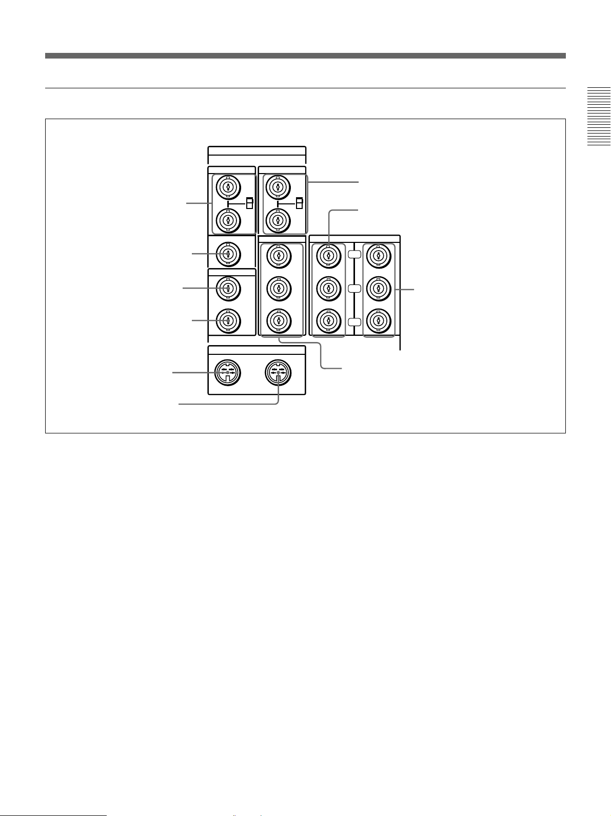
2 Digital input/output section
1 DIGITAL AUDIO (AES/EBU) IN connectors
DIGITAL AUDIO I/O(AES/EBU) SDTI(QSDI)
CH-1/2
CH-3/4
IN
!º VIDEO OUT 1, 2, and 3 (SUPER) connectors
(BNC type)
These connectors output analog composite video
signals.
When the CHARACTER switch on the subsidiary
control panel is set to ON, connector 3 (SUPER)
outputs a signal with superimposed text information.
2 SDTI(QSDI) INPUT connector
3 SDTI(QSDI) OUTPUT connector
4 i.LINK connector (optional DSBK-190
i.LINK/DV Input/Output Board)
i.LINK
INPUT OUTPUT
SDI INPUT SDI OUTPUT
OUT
CH-1/2
5 DIGITAL AUDIO
CH-3/4
6 SDI INPUT connectors
(AES/EBU) OUT connectors
1 DIGITAL AUDIO (AES/EBU) IN connectors
(BNC type)
Input digital audio signals in AES/EBU format to these
connectors.
The left-hand connector (CH-1/2) is for audio channels
1 and 2, and the right-hand connector (CH-3/4) is for
audio channels 3 and 4.
2 SDTI (QSDI) (Serial Data Transport Interface
(QSDI)) INPUT connector (BNC type)
Input digital video and audio signals in SDTI (QSDI)
format to this connector.
3 SDTI (QSDI) (Serial Data Transport Interface
(QSDI)) OUTPUT connector (BNC type)
This connector outputs digital video and audio signals
in SDTI (QSDI) format.
123
(SUPER)
7 SDI OUTPUT 1, 2, and 3 (SUPER)
connectors
Note
When searching at speeds in the range +1 to +1/30 or
1
/30 to –1 times normal speed, the audio signal output
–
from this connector and monitored on external
equipment may sound differently from the audio signal
played back on this unit.
4 i.LINK connector (6-pin IEEE-1394)(optional
DSBK-190 i.LINK/DV Input/Output Board)
This connector is available when the optional DSBK190 i.LINK/DV Input/Output Board is fitted.
This connector inputs and outputs digital video and
audio signals in DV format.
Note
When searching at speeds in the range +1 to +1/30 or
1
/30 to –1 times normal speed, the audio signal output
–
from this connector and monitored on external
equipment may sound differently from the audio signal
played back on this unit.
30 Chapter 1 Overview
Page 31

5 DIGITAL AUDIO (AES/EBU) OUT connectors
(BNC type)
These connectors onput digital audio signals in AES/
EBU format.
The left-hand connector (CH-1/2) is for audio channels
1 and 2, and the right-hand connector (CH-3/4) is for
audio channels 3 and 4.
6 SDI (Serial Digital Interface) INPUT connectors
(BNC type)
Input digital video and audio signals in SDI (D1)
format to the left-hand connector. The right-hand
connector is for an active-through connection.
2 CONTROL PANEL connector (D-sub 15-pin)
When using the optional DSBK-200 Control Panel to
remotely control this unit, connect the DSBK-200 to
this connector.
Chapter 1 Overview
3 REMOTE-IN connector (D-sub 9-pin)
When controlling this unit from an editing controller
such as the ES-7, PVE-500, BVE-600/800/910, or
RM-450/450CE, connect the unit to the editing
controller via this connector using the supplied 9-pin
remote control cable.
When controlling another VCR from this unit, connect
the VCR to this connector.
7 SDI (Serial Digital Interface) OUTPUT 1, 2 and
3 (SUPER) connectors (BNC type)
These connectors output digital video and audio
signals in SDI (D1) format.
When the CHARACTER switch on the subsidiary
control panel is set to ON, connector 3 (SUPER)
outputs a signal with superimposed text information.
3 External device connectors
VIDEO CONTROL
1 VIDEO CONTROL connector
CONTROL PANEL
2 CONTROL PANEL connector
REMOTE-IN
3 REMOTE-IN connector
REMOTE-OUT
4 REMOTE-OUT connector
4 REMOTE-OUT connector (D-sub 9-pin)
This connector provides the loop-through output for
remote control signals from the REMOTE-IN
connector.
4 Analog audio input/output section
1 AUDIO IN −6dBm/0dBm/+4dBm switches
2 AUDIO IN LEVEL/600Ω switches
MONITOR AUDIO
AUDIO IN
AUDIO OUT
LEVEL
OFF
0dBm
-6dBm +4dBm
CH-1
CH-1
HIGHLOW
ON
-600
Ω
OFF
-6dBm +4dBm
CH-2 CH-3
CH-2 CH-3
LEVEL
0dBm
HIGHLOW
ON
-600
Ω
LEVEL
HIGHLOW
ON
-600
OFF
0dBm
-6dBm +4dBm
LEVEL
Ω
ON
OFF
0dBm
-6dBm +4dBm
CH-4
CH-4
HIGHLOW
-600
Ω
1 VIDEO CONTROL connector (D-sub 15-pin)
For remote control of the internal digital video
processor, connect an optional remote control unit
such as the UVR-60/60P or BVR-50/50P to this
connector.
Note
Always power off this unit before connecting the
remote control unit.
5 AUDIO OUT CH-1 to CH-4
connectors
4 AUDIO IN CH-1 to CH-4 connectors
3 MONITOR AUDIO connector
1 AUDIO IN −6dBm/0dBm/+4dBm switches
Set these switches according to the audio input levels
to the AUDIO IN CH-1 to CH-4 connectors.
Chapter 1 Overview 31
Page 32

Location and Function of Parts
2 AUDIO IN LEVEL/600Ω switches
Set these switches for each channel as shown in the
following table, according to the audio input levels to
the AUDIO IN CH-1 to CH-4 connectors and the
impedance.
Chapter 1 Overview
Settings of the AUDIO IN LEVEL/600Ω switches
Audio input
Level Impedance
−60dBs
(microphone input)
+4dBs/0dBs/−6dBs
(line audio input)
+4dBm/0dBm/−6dBm
(line audio input)
High impedance
(about 20kΩ)
High impedance
(about 20kΩ)
600Ω HIGH-ON
3 MONITOR AUDIO connector (RCA phono
jack)
This connector outputs audio signals for monitoring.
The audio signals to be output from this connector can
be selected with the MONITOR SELECT buttons on
the lower control panel.
Switch setting
LOW-OFF
(left position)
HIGH-OFF
(middle position)
(right position)
4 AUDIO IN CH-1 (channel 1) to CH-4 connectors
(XLR 3-pin, female)
Use these connectors to connect separate channels of
audio input from a player VCR or other external audio
equipment.
5 AUDIO OUT CH-1 (channel 1) to CH-4
connectors (XLR 3-pin, male)
These connectors output channel-1 to channel-4 audio
signals, respectively.
In 2-channel audio recording mode (selected with
extended menu item 818), it is possible to use the
AUDIO OUT CH-3 and AUDIO OUT CH-4
connectors for monitor audio output for channels 1 and
2, respectively (use extended menu item 820).
32 Chapter 1 Overview
Page 33

Usable Cassettes
This unit can use the DVCAM cassettes listed below.
Model name Size
PDV-64ME/94ME/124ME/184ME Standard size
PDVM-12ME/22ME/32ME/40ME Mini size
The numbers in each model name indicate the
maximum recording/playback time (in minutes) for
each model. For example, the PDV-184ME has a
maximum recording/playback time of 184 minutes.
Cassettes usable for playback only
All consumer DV cassettes and L- and M-size
DVCPRO (25M) cassettes are usable for playback
only.
Notes
•If you insert an incorrect type of cassette, it will be
automatically ejected.
•When operating this unit as a player, you can also use
DV cassettes on the unit. However, it is the best
choice to always use DVCAM cassettes because they
are more reliable than DV cassettes whatever your
purpose may be: playback, editing, or long-period
storage of recordings.
•Cassettes that have been recorded by a DV-format
recorder can be played back on this unit but cannot be
used for recording at editing operation such as the
setting of edit points. When you insert such a
cassette into this unit, the NOT EDITABLE indicator
lights up in the lower control panel display section.
Notes on using cassettes
•Before storing the cassette, rewind the tape to the
beginning and be sure to put the cassette in its storage
case, preferably on end instead of flat on its side. The
storage case of a DVCAM cassette is specially
designed to ensure a long-period storage of the tape.
Storing a cassette in any other condition (not
rewound, out of its case, etc.) may cause the video
and audio contents to become damaged over time.
•If the cassette memory connector (contact point)
becomes dirty, connection problems may occur,
causing a loss of functions. Remove away any dust
or dirt from this area before using the cassette.
•If the cassette is dropped on the floor or otherwise
receives a hard impact, the tape may become
slackened and may not record and/or play back
correctly.
For information about how to check the tape for slack, see
the next section.
Checking the tape for slack
Using a paper clip or a similar object, turn the reel
gently in the direction shown by the arrow. If the reel
does not move, there is no slack. Insert the cassette
into the cassette compartment, and after about 10
seconds take it out.
Chapter 1 Overview
DVCAM cassettes
The following figure illustrates the DVCAM cassette’s
appearance.
REC/SAVE switch
For details of this switch, see “Preventing
accidental erasure”
Mini size
Cassette memory
This memory is used to store ClipLink log data.
For details of ClipLink log data, see the
appendix “ClipLink Guide”
(page 34)
.
Standard size
(page 147)
.
Paper clip, etc.
Reel
Chapter 1 Overview 33
Page 34

Location and Function of Parts
Preventing accidental erasure
Set the REC/SAVE switch on the cassette to SAVE to
prevent accidental erasure of recorded contents.
Chapter 1 Overview
REC/SAVE switch
Set to SAVE
REC
SAVE
To enable re-recording
Set the cassette’s REC/SAVE switch to REC.
When this switch is set to SAVE, the unit cannot
record on the tape.
Inserting and Ejecting Cassettes
Inserting a cassette
This unit accepts three sizes of cassette: L (standard
size), M (medium size: DVCPRO) and S (mini size).
When inserting a cassette in the unit, make sure its
tape window faces upward as shown in the following
figure.
Outer guides
Tape window facing upward
Inner guides
Tape window facing upward
Ejecting a cassette
Mini size (Insert the cassette
into the middle of the cassette
compartment.)
Standard size
Medium size (Align the
cassette with the outer
guides, then slide it in over
the inner guides.)
34 Chapter 1 Overview
Press the EJECT button.
EJECT button
Page 35

Chapter2
Setting/Displaying
Time Data and Text
Information
Displaying Time Data and Unit's Operating Status−
Superimposing Text Information
To display superimposed time data and text information about the
operating status of the unit on the monitor, set the CHARACTER switch
on the subsidiary control panel to ON.
When the CHARACTER switch is set to ON, the text information is
superimposed on the output of the VIDEO OUT 3 (SUPER) connector and
also of the SDI OUTPUT 3 (SUPER) connector.
Chapter 2 Setting/Displaying Time Data and Text Information
To adjust the displayed text
You can adjust the position, size, and type of superimposed information
using setup menu items 002, 003, 009, and 011.
For details, see pages 108 and 109.
Chapter 2 Setting/Displaying Time Data and Text Information 35
Page 36

Displaying Time Data and Unit's Operating Status−Superimposing T ext
Information
Information displayed
The figure below shows the time data and operation status that can be
superimposed.
1 Time data type
Time data
2 Timecode reader drop-
frame mark
a)
3 Timecode generator
drop-frame mark
a)
Chapter 2 Setting/Displaying Time Data and Text Information
4 VITC field
TCR 23 : 59 . 40. 18 *
PSHUTTLESTILL
6 Operating mode
5 Recorder/player selection
a) This character can appear on the DSR-2000 only. The character to
appear in these two columns is always a colon (:) on the DSR-2000P.
Note
The example above shows the factory default configuration.
You can use setup menu item 005 to display a different type of time data in
the second line as well.
For details, see page 108.
1 Time data type
Display Meaning
CNT Count value of the time counter (COUNTER)
TCR Timecode reader timecode data
UBR Timecode reader user bits data
TCR. VITC reader time code data
UBR. VITC reader user bits data
TCG Timecode generator timecode data
UBG Timecode generator user bits data
IN IN point time data
OUT OUT point time data
AI Audio IN point time data
AO Audio OUT point time data
DUR The duration between any two of the four edit points (IN, OUT,
a)
T*R
a)
U*R
a) “*” appears when data has not been correctly read from tape.
AUDIO IN, AUDIO OUT)
Time code data from time code reader. The asterisk indicates an
interpolation by the time code reader to make up for the time code
data not correctly read from the tape.
User bit data from the time code reader. The asterisk indicates that
last data is retained by the time code reader, as the new data has
not been read correctly from the tape.
36 Chapter 2 Setting/Displaying Time Data and Text Information
Page 37

2 Time code reader drop-frame mark (for DSR-2000 only)
. Drop frame mode (factory default setting)
: Non-drop frame mode
3 Time code generator drop-frame mark
(for DSR-2000 only)
. Drop frame mode (factory default setting)
: Non-drop frame mode
4 VITC field
“ ” (blank): Fields 1 and 3
“*”: Fields 2 and 4
5 Recorder/player selection
The indication changes depending on the status of the RECORDER/
PLAYER buttons.
No display: Neither of the RECORDER and PLAYER buttons is lit.
P: The PLAYER button is lit.
R: The RECORDER button is lit.
6 Operation mode
The field is divided into three blocks, A, B and C.
•Block A displays the operation mode.
•Block B displays the servo lock status or tape speed.
•Block C displays a p mark to indicate an edit section during automatic
editing.
ABC
Chapter 2 Setting/Displaying Time Data and Text Information
Chapter 2 Setting/Displaying Time Data and Text Information 37
Page 38

Displaying Time Data and Unit's Operating Status−Superimposing T ext
Information
Chapter 2 Setting/Displaying Time Data and Text Information
Display
Block A Block B
CASSETTE OUT
TAPE UNTHREAD Tape has not been threaded
STANDBY OFF Standby off mode
T.RELEASE Tape tension released
STOP Stop mode
F.FWD Fast forward mode
REW Rewind mode
PREROLL Preroll mode
PLAY Playback mode (servo unlocked)
PLAY Playback mode (servo locked)LOCK
PLAY Deviation from normal
speed (%)
REC Record mode (servo unocked)
REC LOCK Record mode (servo locked)
EDIT Edit mode (servo unlocked)
EDIT LOCK Edit mode (servo locked)
JOG STILL A still picture in jog mode
JOG FWD Jog mode in forward direction
JOG REV Jog mode in reverse direction
SHUTTLE (Speed) Shuttle mode
VAR (Speed) Variable mode
AUTO EDIT Automatic editing mode
PREVIEW Preview mode
REVIEW Review mode
DMC (Speed)
D-PREV (Speed)
D-EDIT (Speed)
DMC-SPD (Speed) DMC initial speed setting
a)
a)
a)
Operation mode
Cassette is not loaded
Capstan override mode
DMC playback speed
DMC editing preview mode
DMC editing mode
a) Initial speed settings or stored speed settings
38 Chapter 2 Setting/Displaying Time Data and Text Information
Page 39

Setting Time Code and User Bits
Setting an Initial Time Code Value
Set the buttons and switches as shown below.
CHARACTER switch
DF/NDF switch
FREE RUN/REC RUN switch
REMOTE button
Chapter 2 Setting/Displaying Time Data and Text Information
INT/EXT−PRESET/REGEN switch
Button/switch settings
Buttons/switches Settings
REMOTE button
CHARACTER switch ON
INT/EXT−PRESET/REGEN switch INT−PRESET
FREE RUN/REC RUN switch
DF/NDF switch As required
Off
As required
To set an initial time code value, use the following procedure.
RESET button
127
Display section
(3),4
5
FREE RUN/REC RUN switch
Chapter 2 Setting/Displaying Time Data and Text Information 39
Page 40

Setting Time Code and User Bits
Chapter 2 Setting/Displaying Time Data and Text Information
1 Press the COUNTER SEL button and select TC.
Time data type indicator TC lights in the display section of the lower
control panel.
2 Press the HOLD button.
The first digit of the time counter display
(hours:minutes:seconds:frames) in the display section begins to flash.
To set all digits to 0
Press the RESET button.
3 Confirm the JOG indicator in the display section is lit.
If not lit, press the search dial to select jog mode.
4 Select the digit to set by rotating the search dial.
The flashing digit changes to the digit on the right when you rotate the
search dial clockwise, and to the digit on the left when you rotate it
counterclockwise.
5 Set the value for the flashing digit by rotating the search dial while
pressing the SEARCH button.
6 Repeat steps 4 and 5 until you finish setting all digits.
7 Press the SET button.
If the FREE RUN/REC RUN switch is set to FREE RUN, the time
code starts to advance immediately.
To set time code to the current time
1 Set the FREE RUN/REC RUN switch and DF/NDF switch (for DSR-
2000 only) on the subsidiary control panel to FRR RUN and DF,
respectively.
2 Carry out steps 1 to 6 of the previous section “Setting an initial time
code value” to set the time code to a time slightly ahead of the current
time.
3 Press the SET button at the instant when the current time matches the
displayed time code.
40 Chapter 2 Setting/Displaying Time Data and Text Information
Page 41

To set user bits
You can record up to 8 hexadecimal digits of information (date, time,
event number, etc.) in the time code track.
Proceed as follows.
Display section
1
1 Watching the time data type indicator in the display section, press the
COUNTER SEL button and select U-BIT.
2 Carry out steps 2 to 7 of the section “Setting an initial time code
value” (page 39).
Settings are made in hexadecimal (0, 1, 2,... 8, 9, A, B,... E, F).
Chapter 2 Setting/Displaying Time Data and Text Information
Chapter 2 Setting/Displaying Time Data and Text Information 41
Page 42

Setting Time Code and User Bits
Synchronizing the Internal Time Code Generator With an External
Signal—External Lock
Chapter 2 Setting/Displaying Time Data and Text Information
You can synchronize the internal time code generator to an external time
code signal (TC) input to this unit. Use this method to synchronize the
time code generators of a number of VCRs, or to carry out recording
maintaining the synchronization between the source video and time code.
In this case, the settings of the FREE RUN/REC RUN switch and DF/NDF
switch on the subsidiary control panel are ignored.
You can synchronize the internal time code generator to one of the
following external time codes.
•The time code (TC) output of an external time code generator or external
VCR connected to the TIME CODE IN connector
•The time code (VITC) present in a video signal input to the unit
•The time code (TC) input to the SDTI(QSDI) INPUT connector or
i.LINK connector (when fitted with the optional DSBK-190) of the unit
To synchronize to an external time code signal
Proceed as follows.
1
TIME CODE
IN
OUT
1 • When synchronizing to an external time code
Connect the time code output of the external time code generator or
external VCR to the TIME CODE IN connector.
• When synchronizing to the time code (VITC) in an input video
signal
In the input selection section, select an input video signal containing
VITC, then select TC or VITC with extended menu item 613.
Select TC or VITC with extended menu item 613.
1
2
42 Chapter 2 Setting/Displaying Time Data and Text Information
Page 43

2 Set switches on the subsidiary control panel as follows.
TC SELECT switch: TC or VITC according as you are
synchronizing to TC or VITC
NT/EXT–PRESET/REGEN switch: EXT–REGEN (left position)
VITC switch: ON (when recording VITC)
This starts the internal time code generator running in synchronization
with the external time code generator.
Once the internal time code generator is synchronized with the external
time code generator, even if the external time code generator
connection is removed, the internal time code generator continues to
run.
Note
When the input mode is V:SDTI, SDTI or i.LINK (the V:SDTI, SDTI or
i.LINK indicator is lit in the input selection/audio mode display section),
then setting the INT/EXT−PRESET/REGEN switch to EXT−REGEN
automatically synchronizes the internal time code generator to the time
code transferred through the SDTI(QSDI) INPUT connector or i.LINK
connector (when fitted with the optional DSBK-190).
Note that when the INT/EXT−PRESET/REGEN switch is set to EXT−
REGEN, the advance mode and frame count mode (DSR-2000 only) are
automatically set as follows.
Advance mode: free running
Frame count mode (DSR-2000 only): the same as the external time
code signal (drop frame or non-drop frame)
Chapter 2 Setting/Displaying Time Data and Text Information
To check the synchronization to the external signal
Press the STOP button to stop this unit, then press the REC button.
Watch the time counter display, and check that the values displayed
coincide with the external time code values.
Chapter 2 Setting/Displaying Time Data and Text Information 43
Page 44

Page 45

Recording and
Playback
Chapter3
Recording
Preparations for Recording
Buttom/switch settings
MONITOR SELECT buttons
select the audio channels to be monitored.
POWER switch: 1 side
REC controls
adjust the audio recording levels.
(page 16)
:
(page 17)
This section describes video and audio recording on the unit.
Before beginning recording, make any necessary button/switch settings.
For details of the settings of each of the buttons/switches, see the pages indicated
in parenthesis.
:
Input selection section
video and audio signals.
(page 14)
: select the input
REMOTE button
(page 15)
Chapter 3 Recording and Playback
: unlit
REC INHIBIT switch
INT/EXT–PRESET/REGEN switch
select the time code to be recorded.
(page 26)
: OFF
(page 26)
COUNTER SEL button
18
: select the data to be
displayed (counter’s count, time
code value, or user bit value)
PB/EE button
:
TC SELECT switch
VITC switch
(page 26)
(page 18)
(page 26)
: ON (when recording VITC)
: lit
: TC or VITC (when displaying time code)
Chapter 3 Recording and Playback 45
(page
Page 46

Recording
To change the number of audio channels to be recorded
Change the setting of extended menu item 818 between 2-channel (2CH)
mode and 4-channel (4CH) mode (4CH).
Adjusting the audio recording levels
When carrying out audio recording at a reference level
Leave the REC controls pressed in. The audio signals will be recorded at a
preset reference level.
Manually adjusting the recording levels
For each channel, pull out the REC control in the upper control panel, and
adjust so that the audio level indication is 0 dB for an average volume.
Carry out the adjustment in E-E mode.
Chapter 3 Recording and Playback
For details of selecting the E-E mode, see the description of the REC button in the
tape transport control section (page 22) and the PB/EE button in the monitor/
menu/display setting section (page 17).
To change the display range of the audio level meters
Press the METER FULL/FINE button (see page 16).
Setting the reference level
The analog input reference level is determined by the settings of the
AUDIO IN LEVEL/600 Ω switch (see page 32) and extended menu item
811. When, for example, the AUDIO IN LEVEL/600 Ω switch is set to
+4 dBm (HIGH-ON) and extended menu item 811 to –20 dB, the reference
level is set to –20 dB, causing +4 dBm analog input to be converted into a
–20 dB digital signal.
46 Chapter 3 Recording and Playback
Page 47

Recording Time Code and User Bit Values
There are the following two ways of recording time code:
•Setting an initial value, then recording the output of the internal time code
generator
•Recording the output of the internal time code generator synchronized to
an external time code generator
To set an initial value then record the time code
Use the procedure described in the section “Setting an Initial Time Code
Value” (page 39), then carry out the recording operation (see page 48).
Setting the time code value to the current time
See page 40.
Setting a user bit value
See page 41.
To synchronize the internal time code generator to an external
signal
Chapter 3 Recording and Playback
See page 42.
Chapter 3 Recording and Playback 47
Page 48
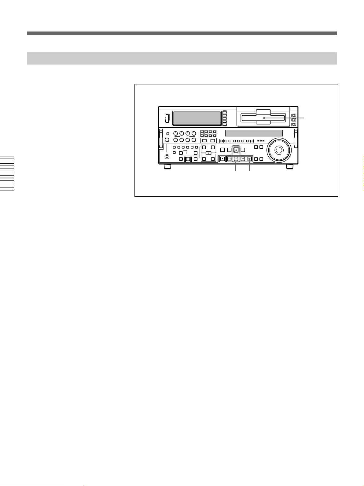
Recording
Recording Operation
Chapter 3 Recording and Playback
To record, use the following procedure.
1
23
1 Insert a cassette.
For details, see the section “Inserting a cassette” (page 34).
2 Hold down the REC button, and press the PLAY button.
Recording starts, the servo locks, and the SERVO indicator in the
display section lights.
3 To stop recording, press the STOP button.
If you record to the end of the tape
The tape is automatically rewound, and stops.
You can change the setting of extended menu item 125 so that the tape just
stops without being automatically rewound when it is recorded to the end.
48 Chapter 3 Recording and Playback
Page 49

Playback
Preparations for Playback
Buttom/switch settings
This section describes playback of video and audio.
Before beginning playback, make any necessary button/switch settings.
For details of the settings of each of the buttons/switches, see the pages indicated
in parenthesis.
MONITOR SELECT buttons
POWER switch: 1 side
PB controls
adjust the audio
playback levels.
(page 17)
:
Time data selection
(page 17)
: select the audio channels to be monitored.
REMOTE button
COUNTER SEL button
select the data to be displayed
(see the section “Displayed time
data” on this page).
PB button
TC SELECT switch
code)(see the section “Displayed time data” on this page)
(page 18)
(page 26)
: lit
: TC or VITC (when displaying time
(page 15)
(page 18)
: unlit
Chapter 3 Recording and Playback
:
Displayed time data
Use the COUNTER SEL button to select one of counter’s count
(COUNTER), time code (TC), and user bit values (U-BIT). When you
select time code, the data displayed is determined by the setting (TC/
VITC) of the TC SELECT switch on the subsidiary control panel as
follows.
TC SELECT switch setting Displayed data
TC TC recorded on tape
VITC VITC recorded on tape
Chapter 3 Recording and Playback 49
Page 50

Playback
Playback Operation
Chapter 3 Recording and Playback
This section describes the following types of playback:
•Normal playback
Playback at normal (×1) speed
•Playback in jog mode
Variable speed playback, with the speed determined by the speed of
turning the search dial
•Playback in shuttle mode
Variable speed playback, with the speed determined by the angular
position of the search dial
•Playback in variable mode
Variable speed playback, with the speed finely determined by the angular
position of the search dial
•Playback using the capstan override function
The playback speed is adjusted temporarily according to the angular
position of the search dial, to align the playback phase with that of
another VCR.
Normal playback
First insert a cassette.
For details of how to insert a cassette, see the section “Inserting and Ejecting
Cassettes” (page 34).
Cassette compartment
Display section
STOP button
PLAY button
To start playback
Press the PLAY button.
Playback starts, the servo locks, and the SERVO indicator in the display
section lights.
50 Chapter 3 Recording and Playback
To stop playback
Press the STOP button.
Page 51

Playback in jog mode
If you play back to the end of the tape
The tape is automatically rewound, and stops.
You can change the setting of extended menu item 125 so that the tape just
stops without being automatically rewound when it is recorded to the end.
In jog mode, you can control the speed of playback by the speed of turning
the search dial. The playback speed range is ±1 times normal speed (can be
changed using extended menu item 116).
To carry out playback in jog mode, use the following procedure.
Display section
1,2,3
1
1 Press the SEARCH button or search dial so that the JOG indicator in
the display section is lit.
Pressing the search dial toggles between jog mode and shuttle mode.
2 Turn the search dial in the desired direction, at the speed
corresponding to the desired playback speed.
Playback in jog mode starts.
3 To stop playback in jog mode, stop turning the search dial.
Chapter 3 Recording and Playback
Chapter 3 Recording and Playback 51
Page 52

Playback
Playback in shuttle mode
Chapter 3 Recording and Playback
In shuttle mode, you can control the speed of playback by the angular
position of the search dial. The range of playback speed is ±32 times
normal speed (can be changed using menu item 102).
There are detents on the search dial at the still position and at ±10 times
normal speed.
To carry out playback in shuttle mode, use the following procedure.
Display section
1,2,3
13
1 Press the SEARCH button or search dial so that the SHUTTLE
indicator in the display section is lit.
Pressing the search dial toggles between jog mode and shuttle mode.
2 Turn the search dial to the desired angle corresponding to the desired
playback speed.
Playback in shuttle mode starts.
3 To stop playback in shuttle mode, return the search dial to the center
position, or press the STOP button.
To return to normal-speed playback
Press the PLAY button.
To alternate between normal-speed playback and shuttle mode
playback
Set the search dial to the position corresponding to the desired shuttle
playback speed, then switch between normal-speed playback and shuttle
playback by pressing the PLAY and SEARCH buttons alternately.
For intermittent shuttle mode playback, press the STOP and SEARCH
buttons alternately.
52 Chapter 3 Recording and Playback
Page 53

Playback in variable mode
In variable mode, you can finely control (61 steps) the speed of playback
in the range of −1 to +2 times normal speed. Noiseless playback is possible
in the range of ±1 times normal speed.
(The variable mode playback speed range can be changed using extended
menu item 119.)
There are detents on the search dial at the still position and at ±1 times
normal speed.
To carry out playback in variable mode, use the following procedure.
Display section
1,2,3
2
1
4
Chapter 3 Recording and Playback
1 Press the VARIABLE button or search dial so that the SHUTTLE
indicator in the display section is lit.
2 If the SEARCH button is lit, press the VARIABLE button, turning it
on.
3 Turn the search dial to the desired angle corresponding to the desired
playback speed.
Playback in variable mode starts.
4 To stop playback in variable mode, return the search dial to the center
position, or press the STOP button.
To return to normal-speed playback
Press the PLAY button.
To alternate between normal-speed playback and variable
mode playback
Set the search dial to the position corresponding to the desired variable
playback speed, then switch between normal-speed playback and variable
playback by pressing the PLAY and VARIABLE buttons alternately.
For intermittent variable mode playback, press the STOP and VARIABLE
buttons alternately.
Chapter 3 Recording and Playback 53
Page 54

Playback
Playback using the capstan override function
You can use the capstan override function to adjust the playback speed
temporarily. This function is convenient for playback phase
synchronization with another VCR playing back the same program.
Display section
1
(A)
Chapter 3 Recording and Playback
(B)
(A),1(B)
,21
1
1 (A) Hold down the PLAY button, and turn the search dial in the
desired direction to adjust the playback speed.
The range of speed adjustment is ±15% in steps of 1%.
(B) Hold down the PLAY button, and press the TRIM buttons to
adjust the playback speed.
The playback speed can be adjusted to ±8% only.
The SERVO indicator in the display section goes off.
2 When the adjustment is completed, release the PLAY button.
The tape transport returns to normal speed, and the SERVO indicator
in the display section lights on again.
54 Chapter 3 Recording and Playback
Page 55

Dynamic Motion Control (DMC) Playback
Overview
DMC playback allows you to vary the playback speed for a certain section
of a tape, in variable mode (from −1 to +1 times normal speed), and store
the varying speed in memory for later playback at the same varying speed.
For example, during a live broadcast of a sporting event you can set the
start and end points of highlights while recording, and then provide
immediate DMC playba -of those highlights.
During DMC playback the tape moves as shown in the following figure.
On-air start point
Waiting for the on-air cue
before starting DMC playback.
Press the REVIEW button
again at the on-air cue.
Starting DMC playback
immediately after preroll
Stop
Preroll point Speed variation start point
Press the REVIEW button.
Normal speed
playback
Press the PREVIEW button.
Normal speed
playback
DMC playback
DMC playback
Speed variation end point
Normal speed playback
Normal speed playback
On-air end point
Chapter 3 Recording and Playback
Stop
Chapter 3 Recording and Playback 55
Page 56

Playback
Storing a varying playback speed in memory
To store the playback speed for DMC playback, use the following
procedure.
MEMORY indicator
Display section
3,5,7
Chapter 3 Recording and Playback
261,5 8
43
1 Press the DMC EDIT button, turning it on.
2 Either while playing back the recorded tape, or during recording, press
the ENTRY button and each of the following buttons simultaneously,
to set the start and end points.
• On-air start point: AUDIO IN button
• Speed variation start point: IN button
• Speed variation end point: OUT button
• On-air end point: AUDIO OUT button
Each press turns the corresponding button on.
3 Press the SEARCH button or search dial so that the SHUTTLE
indicator in the display section is lit.
4 If you want to use the variable mode to set the varying playback speed,
press the VAIRABLE button, turning it on.
5 Holding down the DMC EDIT button, turn the search dial, to set the
initial speed at the speed variation start point.
56 Chapter 3 Recording and Playback
The speed you set appears in the display section. During this period the
tape does not move.
6 Press the PREVIEW button.
The tape is prerolled and played back at normal speed from the on-air
start point to the speed variation start point. On passing the speed
variation start point, the MEMORY indicator begins to flash, and
playback begins at the speed set in step 5.
Page 57

7 Turn the search dial to vary the playback speed.
While the MEMORY indicator is flashing, the speed variations are
stored in memory. On passing the speed variation end point, the
MEMORY indicator changes from flashing to continuously lit, and the
variable speed storing ends.
8 Press the STOP button to stop the tape.
If the MEMORY indicator lights continuously before the speed
variation end point
This indicates that the memory became full at that point. It is therefore not
possible to record more speed variation. The maximum capacity is a
duration of 120 seconds.
To amend the stored speed variation
Press the PREVIEW button.
The interval between the speed variation start and end points is
automatically played back at the stored speed. Operate the search dial as
required, to adjust the playback speed.
Setting the initial speed to normal speed
In step 5, press the PLAY button.
Chapter 3 Recording and Playback
Executing DMC Playback
There are two methods of starting DMC playback.
•Starting playback at the on-air cue from the on-air start point
•Starting playback immediately after preroll
Notes
•To avoid operating mistakes we recommend that you use the VCR in
standalone mode when carrying out DMC playback.
•When using two VCRs connected for editing, you can only use the
recorder VCR for DMC playback, and only when both the RECORDER
and PLAYER buttons are off.
Chapter 3 Recording and Playback 57
Page 58

Playback
Chapter 3 Recording and Playback
You can start DMC playback using either the REVIEW button or
PREVIEW button depending on which of the above two methods you use.
REVIEW button
PREVIEW button
To start playback at the on-air cue from the on-air start point
Use the following procedure.
1 Press the REVIEW button.
The REVIEW button lights, and the tape is cued up to the on-air start
point. After the tape is cued up, the REVIEW button flashes.
2 At the moment the on-air cue is given, press the REVIEW button once
more.
The REVIEW button lights, and playback starts at normal speed.
Between the speed variation start and end points, DMC playback is
carried out at the stored speed, and then playback continues at normal
speed and the tape stops at the on-air end point.
Starting playback immediately after preroll
Press the PREVIEW button.
The PREVIEW button lights, and after preroll, DMC playback is carried
out for the section between the speed variation start and end points, then
playback continues at normal speed from the speed variation end point.
Stopping the tape during DMC playback
Press the STOP button.
58 Chapter 3 Recording and Playback
To exit DMC playback mode
Press the DMC EDIT button and the DELETE button simultaneously.
Page 59

Synchronous Playback
Connecting two DSR-2000/2000P units and synchronizing their tape
transport, you can carry out two-unit synchronous playback with an
accuracy of ±0 frame.
For equipment/signal connections and basic settings, see the section
“Connections for Two-Unit Synchronous Playback” (page 132).
Use the following procedure.
(In the following, the controlling unit is referred to as the recorder (this
unit) and the controlled unit as the player.)
4
1
Chapter 3 Recording and Playback
3,67
2,5
1 Press the PLAYER button, turning it on.
2 Cue up to the player tape position where to start playback.
3 Hold down the ENTRY/SHIFT button, and press the IN button.
The player IN point is set.
4 Press the RECORDER button, turning it on.
5 Cue up to the recorder tape position where to start synchronous
playback.
6 Hold down the ENTRY/SHIFT button, and press the IN button.
The recorder IN point is set.
(Continued)
Chapter 3 Recording and Playback 59
Page 60

Playback
Chapter 3 Recording and Playback
7 Hold down the ENTRY/SHIFT button, and press the PREVIEW
button.
Both the recorder and player start preroll followed by synchronous
playback by the two units.
When setup menu item 004 is set to ON and 305 set to ACCUR on the
recorder side, the recorder and player tape transports are synchronized
during the preroll allowing two-unit synchronous playback with ±0
frame accuracy to start at the player and recorder IN points.
To end synchronous playback while it is in progress
Press the STOP button.
60 Chapter 3 Recording and Playback
Page 61

Digitally Dubbing Signals in DVCAM Format
(Optional DSBK-190 Required When Using i.LINK Interface)
In addition to straightforward tape dubbing, you can also use this unit to
digitally dub signals in DVCAM format automatically from the beginning
of the tape to the end, through an i.LINK or SDTI(QSDI) interface.
When a tape recorded on a DSR-1/1P Digital Videocassette Recorder or
DSR-300/300P Digital Camcorder is dubbed, the ClipLink log data held in
the cassette memory is also copied.
For information about connections and basic settings, see the section
“Connections for Digitally Dubbing Signals in DVCAM Format” (page 133).
Notes
•Use a tape which is recorded in the DVCAM format. A tape recorded in
DV format cannot be used as a source tape for dubbing through an
SDTI(QSDI) or i.LINK interface.
•Regardless of the audio channel settings made in the input selection
section of this unit, dubbing is performed with the original audio
recording mode unchanged (two-channel mode (48 kHz) or four-channel
mode (32 kHz)).
•Approximately the last 2 minutes of the tape may not be copied because
of differences in tape lengths. (If an Index Picture is recorded in this
portion, it may also not be copied.)
•A continuous recorded section of approximately 5 seconds is required
before the recording start point. It is recommended to record beforehand
color bars or a similar signal at the start point of the recording tape to be
used on this unit.
Chapter 3 Recording and Playback
Perform the following procedure.
2,5
7
4
3
1
1 On the recorder, hold down the ENTRY/SHIFT button and press the
MENU button.
The SYSTEM MENU screen appears on the monitor connected to this
unit.
(Continued)
Chapter 3 Recording and Playback 61
Page 62

SYSTEM MENU
SDTI DUBBING
i.LINK DUBBING
Digitally Dubbing Signals in DVCAM Format (Optional DSBK-190 Required
When Using i.LINK Interface)
2 Using the search dial in jog mode, select either SDTI DUBBING or
i.LINK DUBBING, then press the SET button.
The screen changes as follows, allowing you to select a desired group
Chapter 3 Recording and Playback
of items for dubbing.
(In explaining the subsequent operating procedure, illustrations of
screens shown when performing SDTI dubbing are used. You can
follow the same operating procedure also when performing i.LINK
dubbing.)
SYSTEM MENU
SDTI DUBBING
A/V
A/V/TC
A/V/TC/CM
• A/V: Audio and video
• A/V/TC: Audio, video and timecode
• A/V/TC/CM: Audio, video, timecode, and cassette memroy
(ClipLink log data)
62 Chapter 3 Recording and Playback
Page 63

3 Using the search dial, select a desired group of items for dubbing, then
press the SET button.
The menu screen changes as follows.
(Example: The screen displayed when A/V/TC/CM is selected.)
SDTI DUBBING
(A/V/TC/CM)
INSERT RECORD TAPE IN
THIS VTR AND SOURCE
TAPE IN THE PLAYER VTR.
ABORT:MENU KEY
4 Insert the source tape in the player and the recording tape in this unit.
A message to make sure dubbing may be started appears.
SDTI DUBBING
(A/V/TC/CM)
START i.LINK DUBBING?
If the cassette memory capacity is not sufficient
A message urging you to replace the recording tape by a tape with a
larger cassette memory capacity appears.
For more information about this, see the section “If the cassette memory of
the recording tape is not large enough” (page 65).
START:SET KEY
ABORT:MENU KEY
Chapter 3 Recording and Playback
To cancel the dubbing operation
Press the MENU button.
(Continued)
Chapter 3 Recording and Playback 63
Page 64

SDTI DUBBING
(A/V/TC/CM)
EXECUTING.
TCR 00:00:00:00
UBR 00:00:00:00
ABORT:MENU KEY
Digitally Dubbing Signals in DVCAM Format (Optional DSBK-190 Required
When Using i.LINK Interface)
5 Press the SET button.
The recording tape and source tape are both automatically wound back
to the beginning, and dubbing starts. At the same time, the screen
changes as follows.
Chapter 3 Recording and Playback
To end the dubbing operation while it is in progress
Press the STOP button.
The dubbing operation stops and a message asking whether to copy the
contents of the cassette memory appears.
For more information about this, see the section “If you end dubbing while it
is in progress” (page 65).
When dubbing is completed
1 A message “COMPLETED” appears on the monitor.
2 The source tape and recording tape are both automatically rewound
to the beginning, and the cassettes ejected.
3 The unit returns to the state in step 3.
6 To continue by dubbing another tape, repeat steps 4 and 5.
7 To end the dubbing operation and exit from the menu, press the
MENU button.
64 Chapter 3 Recording and Playback
Page 65

If the cassette memory of the recording tape is not large
SDTI DUBBING
(A/V/TC/CM)
CM MEMORY STORAGE
CAPACITY OF THE RECORD
TAPE IS TOO SMALL.
ABORT:MENU KEY
SDTI DUBBING
(A/V/TC/CM)
DUBBING IS ABORTED.
EXECUTE CM COPY?
COPY :SET KEY
NOT COPY:RESET KEY
enough
When you insert the recording tape and source tape in this unit and the
player, respectively, whereas A/V/TC/CM has been selected as the items
for dubbing, their cassette memory contents are checked automatically. If,
as a result, the cassette memory capacity of the recording tape is found
inadequate, the following message appears.
If this message appears, replace the recording tape by a tape with a larger
cassette memory capacity.
Chapter 3 Recording and Playback
If you end dubbing while it is in progress
If you end dubbing while it is in progress with A/V/TC/CM selected as the
items for dubbing, the following message appears.
To copy the contents of the cassette memory, press the SET button.
If you do not wish to copy the contents of the cassette memory, press the
RESET button. If you press the RESET button, however, the contents of
the cassette memory may not agree with the material recorded on the tape.
Chapter 3 Recording and Playback 65
Page 66

Page 67

Automatic Editing
Chapter4
Editing
This section describes how to carry out automatic editing with this unit and
another VCR connected to the REMOTE-IN or REMOTE-OUT connector.
Overview of Automatic Editing
With this unit, you can use the following two edit modes.
•Assemble edit mode
•Insert edit mode
(In this Operating Instructions, these two modes are also referred to simply
as assemble mode and insert mode, respectively.)
Assemble edit mode
In assemble editing, you record video and audio materials in order from
the start of the tape. In addition to video and audio, time code is also
recorded. This edit mode is convenient when you are recording on a new
tape.
Note
Before you begin assemble editing for the first time with a new tape, a
video signal, e.g. a black signal, and time code must be recorded on the
tape in advance of the recorder IN point for a length equal to or greater
than the preroll time.
Chapter 4 Editing
Chapter 4 Editing 67
Page 68

Automatic Editing
Insert edit mode
In insert editing, you insert video, audio, and time code at desired positions
on an already recorded tape. You can insert all three types of data at the
same time or insert one of the types separately.
Note
Before you use an unrecorded tape in insert editing, a video signal, e.g. a
black signal, and time code must be recorded on all over the tape.
You can carry out DMC editing in both edit modes. In insert editing, split
editing is also possible.
To record a video signal and time code on an unrecorded tape
When recording a video signal and time code on an unrecorded tape to use
it as a recording tape in insert editing, you can use a test signal generated
by the internal signal generator of the unit. An example procedure follows.
1 Insert an unrecorded cassette in the unit and rewind it.
Chapter 4 Editing
2 Using the VIDEO IN button in the input selection section (see page
14), select the video test signal (SG) as the input video signal.
3 Set switches on the subsidiary control panel (see page 25) as follow.
INT/EXT-PRESET/REGEN switch: INT−PRESET (right position)
FREE RUN/REC RUN switch: REC RUN
DF/NDF switch: Set as required.
4 Set an initial time code value (see page 39)
5 Carry out recording (see page 48).
Recording time code
For automatic editing, regardless of the settings of the INT/EXT−
PRESET/REGEN switch, time code is recorded continuously from the
previous time code recorded on the tape.
Using extended menu item 610, it is also possible to record time code according to
the settings on the control panels.
68 Chapter 4 Editing
Page 69

Sequence of editing operations
The following flowchart outlines the sequence of operations in automatic
editing with two DSR-2000/2000P units.
Sequence of Operation
Making necessary settings
Insert cassettes.
• Insert a cassette for recording the results of
editing in the recorder.
• Insert the cassette on which material to be edited
has been recorded in the player.
Select an edit mode.
Determine edit points.
See
“Button/Switch Settings for
Editing” (page 70)
“Usable Cassettes” (page
33)
“Selecting an Edit Mode”
(page 71)
“Setting Edit Points” (page
72)
Chapter 4 Editing
Preview the editing results.
Modify edit points as necessary.
Execute automatic editing.
Review the editing results as necessary.
“Checking Editing Results—
Preview” (page 80)
“Modifying Edit Points”
(page 76
“Executing Automatic
Editing” (page 81)
“Reviewing the editing
results” (page 83)
)
Chapter 4 Editing 69
Page 70

Automatic Editing
Notes on video output to the monitor
In E-E mode, the video output of the unit is delayed by the time for video
circuit processing with respect to the input video signal (8H).
Unlike the playback operations described in Chapter 3, for playback to be
carried out in edit mode with both the player and recorder specified, you
can use extended menu item 701 to delay the V-SYNC phase by 8H.
Button/Switch Settings for Editing
Before beginning editing, set buttons and switches on the recorder and
player as follows.
For details of the settings of each of the buttons/switches, see the pages indicated
in parenthesis.
Recorder settings
Chapter 4 Editing
MONITOR SELECT buttons
POWER switch: I side
REC controls
adjust the audio recording
levels.
(page 16)
:
(page 17)
INT/EXT–PRESET/REGEN switch
: select the audio channels to be monitored.
Input selection section
audio signals.
REC INHIBIT switch
TC SELECT switch
(page 26)
: OFF
(page 26)
(page 26)
(page 14)
: TC or VITC, when displaying time code
: select the input video and
REMOTE button
unlit 9PIN (when using
REMOTE-IN/-OUT) or i.LINK
(when using i.LINK) button: lit
COUNTER SEL button
18)
: select the data to be
displayed (counter value or
time code value)
: select the time code to be recorded.
(page 15)
:
(page
70 Chapter 4 Editing
Page 71

Player settings
POWER switch: I side
PB controls
adjust the audio playback
levels.
(page 17)
:
Selecting an Edit mode
PB button
TC SELECT switch
(page 18)
(page 26)
REMOTE button
9PIN (when using REMOTEIN/-OUT) or i.LINK (when
using i.LINK) button: lit
COUNTER SEL button
18):
select the data to be
displayed (counter value or
time code value)
: lit
: TC or VITC, when displaying time code
(page 15)
(In the subsequent description, except where the player is explicitly
mentioned, operations are all on the recorder.)
: lit
(page
Chapter 4 Editing
Select either assemble mode or insert mode.
INSERT buttons
IN button and OUT button
ASSEMBLE button
Depending on the desired edit mode, press the following button or buttons.
•For assemble editing: ASSEMBLE button
•For insert editing: the desired INSERT buttons (VIDEO, CH-1 to CH-4,
TIME CODE)
When you select an edit mode, the IN and OUT buttons begin to flash,
indicating that the edit points require setting.
Chapter 4 Editing 71
Page 72

Automatic Editing
Setting Edit Points
To set edit points
Of the four edit points (recorder IN and OUT points, and player IN and
OUT points) required, set any three. The last edit point is set
automatically.
In insert mode, you can set the edit points for video and audio separately
(split editing).
For details of setting split edit points, see the section “Setting split edit points”
(page 73).
Chapter 4 Editing
2
3
1
1 Press the RECORDER button or PLAYER button to select the VCR on
which you will set edit points.
The button which you have pressed lights.
2 Turn the search dial in jog or shuttle mode, and position the tape at the
required edit point.
For details of playback in jog or shuttle mode, see the sections “Playback in
jog mode” (page 51) and “Playback in shuttle mode” (page 52).
3 At the point at which you wish to set the IN point or OUT point, hold
down the ENTRY/SHIFT button and press the IN button or OUT
button as the case may be.
When the IN point or OUT point is set, the IN button or OUT button
correspondingly lights.
72 Chapter 4 Editing
4 Repeat steps 1 to 3 until three of the four edit points (recorder IN and
OUT points, and player IN and OUT points) are set.
When the IN points on both the recorder and player are set, the
PREVIEW button and AUTO EDIT button flash, indicating that it is
possible to carry out a preview or editing operation.
Page 73

Setting split edit points
Notes
In the following cases, the DELETE button begins to flash and you cannot
carry out automatic editing.
•The OUT point is before the IN point.
•All four of the recorder IN and OUT points and the player IN and OUT
points have been set.
Use the DELETE button to delete a redundant edit point, or set the edit
points correctly.
For details of deleting edit points, see the section “To delete an edit point” (page
77).
In split editing, you can set the edit points for audio and video
independently. Set the audio edit points with the AUDIO IN/OUT buttons,
and the video edit points with the IN/OUT buttons.
Note that split editing is only possible when the recorder is set for insert
editing.
3
1 4
2
1 Press the appropriate INSERT button (VIDEO, CH-1 to CH-4, or TC).
The IN and OUT buttons flash.
2 Press the RECORDER or PLAYER button to select the VCR for
which edit points are to be set.
The button you have pressed lights.
3 To find the edit point, rotate the search dial in jog or shuttle mode.
For details of jog/shuttle mode playback, see the sections "Playback in jog
mode" (page 51) and “Playback in shuttle mode” (page 52).
4 Hold down the ENTRY/SHIFT button and press one of the IN, OUT,
AUDIO IN, and AUDIO OUT buttons, to set the edit point.
Chapter 4 Editing
(Continued)
Chapter 4 Editing 73
Page 74
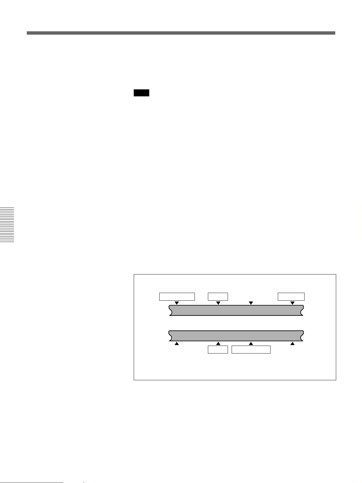
Automatic Editing
5 Repeat steps 2 through 4 to set the required edit points.
As each edit point is set, the corresponding button changes from
flashing to continuously lit.
Note
During split editing, if you set six or more edit points for the recorder and
player, the DELETE button starts to flash, to indicate that editing cannot
be executed. Delete all excess edit points, using the DELETE button.
For details of deleting edit points, see the section “To delete an edit point” (page
77).
Automatic setting of edit points in split editing
Split editing requires a total of eight edit points: four video edit points
(player IN and OUT and recorder IN and OUT) and four audio edit points
(player audio IN and OUT and recorder audio IN and OUT). However, as
soon as you set five points, the system automatically calculates and sets the
remaining three points. Specifically, once you have set three of the four
video edit points and two audio edit points, the remaining three edit points
are set automatically, regardless of whether these points are for the
recorder or player.
Chapter 4 Editing
In the figure below, the edit points shown within boxes are already set. The
other edit points (recorder audio OUT point, and player audio IN and video
OUT points) are set automatically.
Note that, regardless of whether it was set manually or automatically, any
edit point can be deleted or corrected later.
Audio IN point IN point
Recorder
Player
Audio IN point IN point
You can set audio cut in, crossfade, fade in, and fade out effects using extended
menu item 317.
Audio OUT point OUT point
Audio OUT point
OUT point
74 Chapter 4 Editing
Page 75

When the audio IN point is not set for insert editing of audio
only
As long as the audio OUT point is set, the VCR is ready for preview or
editing. If the audio IN point has not been set, the current tape position is
automatically used as the audio IN point.
Using a VCR without a split editing function as the player
If it is not possible to set separate audio and video edit points on the VCR
you are using as the player, by setting the audio IN and OUT points on the
recorder (this unit), then setting three video edit points, split editing is
possible.
Checking Edit Points
You can check the time value for an edit point and the duration between
two edit points by displaying them in the display section.
To display the time value for an edit point
Use the following procedure.
Display section
2
1
1 Press the RECORDER button or PLAYER button to select the VCR on
which you wish to check the edit point.
The button you have pressed lights.
2 Hold down the IN, OUT, AUDIO IN, or AUDIO OUT button
according to the edit point you wish to check.
While you hold down the button, the time value of the edit point is
shown in the display section.
Chapter 4 Editing
Chapter 4 Editing 75
Page 76

Automatic Editing
To display the duration between two edit points
1 Press the RECORDER button or PLAYER button to select the VCR on
which you wish to check the duration.
The button you have pressed lights.
2 Hold down any two of the four edit points (recorder or player IN,
OUT, audio IN, and audio OUT points).
While you hold down the buttons, the duration between the two edit
points is shown in the display section.
When only one of the two selected edit points is set
The duration between the edit point and the current tape position is
displayed.
Chapter 4 Editing
When neither of the two selected edit points is set
The duration between the most recently set corresponding edit points is
displayed.
Modifying Edit Points
Once you set edit points, you can modify or delete them as required.
When edit points have been set incorrectly, for example when an OUT
point is located before an IN point or when the duration of editing
segments on the player and recorder do not match, the DELETE buttons
flash to alert you that a preview or edit cannot be carried out. In this case,
either modify the erroneous edit point, or first delete it and then enter it
correctly.
To turn a flashing DELETE button off
The DELETE button goes off when the erroneous edit point is correct.
76 Chapter 4 Editing
Page 77

To modify an edit point
Use the following procedure.
Display section
To delete an edit point
2
1
1 Press the RECORDER button or PLAYER button to select the VCR on
which you wish to modify the edit point.
The button you have pressed lights.
2 Hold down the IN, OUT, AUDIO IN, or AUDIO OUT button
corresponding to the edit point you wish to modify, and press the
TRIM buttons (+ or –).
While you hold down the button, the time value for the edit point
appears in the display section; pressing the +button increases the value
by one frame, and pressing the –button decreases it by one frame.
To delete an edit point, use the following procedure. You can use the same
procedure whether or not the DELETE button is flashing.
Chapter 4 Editing
2
1
(Continued)
Chapter 4 Editing 77
Page 78

Automatic Editing
Cuing Up to Edit Points
To cue up to an edit point
1 Press the RECORDER button or PLAYER button to select the VCR on
which you wish to delete the edit point.
The button you have pressed lights.
2 Hold down the DELETE button and press the IN, OUT, AUDIO IN, or
AUDIO OUT button according to the edit point you wish to delete.
The edit point is deleted, and the DELETE button goes off.
You can cue up to any edit point, or cue up to a position located a specified
amount of time before the edit start point (preroll).
Chapter 4 Editing
Use the following procedure.
2
1
1 Press the RECORDER button or PLAYER button to select the VCR on
which you wish to cue up to an edit point.
The button you have pressed lights.
2 Hold down the IN, OUT, AUDIO IN, or AUDIO OUT button
according to the edit point to which you wish to cue up, and press the
PREROLL button.
78 Chapter 4 Editing
The edit point you have selected is cued up.
Page 79

To preroll
Use the following procedure.
2
1
1 Press the RECORDER button or PLAYER button to select the VCR on
which you wish to carry out a preroll.
The button you have pressed lights.
2 Press the PREROLL button.
The tape is wound back to a position 5 seconds (factory default setting)
before the edit IN point, and stops.
To change the preroll time
The factory default setting for the preroll time is 5 seconds, but you can
use basic menu item 001 to change this to any value from 0 to 30 seconds.
If you change the preroll time, make sure that the setting is not longer than
the recording length before the edit IN point.
Note that for automatic editing, the preroll time setting on the recorder
takes precedence.
Chapter 4 Editing
Chapter 4 Editing 79
Page 80

Automatic Editing
Checking Edit Results—Preview
When you have set the edit points, the PREVIEW button flashes,
indicating that you can carry out a preview.
PREVIEW button
Chapter 4 Editing
To carry out a preview, press the PREVIEW button.
The PREVIEW button changes from flashing to continuously lit, and the
preview is carried out.
At the end of the preview, the PREVIEW button flashes again.
To stop the preview
Press the STOP button.
The tape stops at the position where you pressed the button.
To return the tape to the preroll point
Press the PREROLL button.
To return the tape to the IN point or OUT point
Press the PREROLL button and the IN button or OUT button
simultaneously.
After the preview, make any necessary adjustments to the edit points, then
repeat the preview.
For details of how to modify or delete edit points, see the section “Modifying Edit
Points” (page 76).
80 Chapter 4 Editing
Page 81

Monitor output during a preview
During a preview, you can monitor the following video and audio on a
monitor connected to the recorder.
•From the preroll point to the IN point, you can monitor the playback from
the recorder.
•From the IN point to the OUT point, you can monitor the playback from
the player through the recorder in E-E mode.
•From the OUT point to the postroll point, you can monitor the playback
from the recorder.
The following figure illustrates this.
Executing Automatic Editing
Overview of editing operations
Preroll point
Recorder
Preroll
IN point
Playback (recorder)
E-E mode (player)
OUT point
Playback (recorder)
The figure below shows how the recorder and player operate during
editing.
Tape transport
IN point
Editing results
OUT point Postroll point
Postroll
Chapter 4 Editing
Time flow
Player
Playback
Recording overlap
(When editing in
assemble mode)
Stop
Stop
Chapter 4 Editing 81
Page 82

Automatic Editing
Monitor output during an edit
During execution of an automatic edit, on a monitor connected to the
recorder, you can monitor the same video and audio as during a preview
(see page 81).
However, during preread editing (see page 87), only the playback from the
recorder can be monitored.
Using a single monitor for video and audio on both player and recorder
For efficient editing if only one monitor is available, use the following
method.
1 Connect the monitor to the recorder.
2 In the setup menus, set item 008 to “AUTO”.
3 Press the PLAYER button on the recorder.
Chapter 4 Editing
Starting automatic editing
This forces the recorder to E-E mode, in which the player video and
audio signals are output to the monitor.
Note
Continuous recording must exist on the recorder tape to be used in issert
editing. It is not possible to carry out editing on a section of the tape with
no signal recorded.
When you have set the edit points, press the flashing AUTO EDIT button.
The AUTO EDIT button changes from flashing to continuously lit, and the
automatic editing operation begins.
At the end of the editing operation, the AUTO EDIT button goes off.
ENTRY/SHIFT button
DELETE button
AUDIO EDIT button
82 Chapter 4 Editing
PREVIEW button
OUT button STOP button
REVIEW button
Page 83

To change the OUT point after starting automatic editing
operation
After starting the automatic editing operation, to end the operation before
the preset OUT point, hold down the ENTRY/SHIFT button and press the
OUT button.
The position where you pressed the button becomes the OUT point, and
editing ends.
To abandon automatic editing
Press the STOP button.
The automatic editing operation is abandoned. At the same time, the
PREVIEW button and AUTO EDIT button start flashing, and the state
before the editing was started is restored.
In this case, the IN and OUT points already set are preserved so that you
can carry out a preview or automatic editing operation again by pressing
the PREVIEW button or AUTO EDIT button.
Reviewing the editing results
After carrying out an editing operation, you can carry out a review, to
check the editing results on the monitor.
To carry out a review, after carrying out the edit, and before you set any
new edit points or make other settings, press the REVIEW button.
The REVIEW button lights, and the review is carried out.
At the end of the review the REVIEW button goes off, and the tape returns
to the OUT point.
Chapter 4 Editing
After automatic editing, to adjust the edit points and reexecute
the edit
Hold down the DELETE button and press the ENTRY/SHIFT button to
recall the edit points. After adjusting the edit points, press the AUTO
EDIT button to carry out the edit again.
For details of how to adjust edit points, see the section “Modifying Edit Points”
(page 76).
Chapter 4 Editing 83
Page 84

DMC Editing
Overview of DMC Editing
You can carry out variable speed editing, controlling the player playback
speed from the recorder.
The following figure illustrates how the tapes move on both the player and
recorder during DMC editing.
Chapter 4 Editing
Preroll
Recorder
Preroll time × initial speed
Player
Playback
Tape
moves at
initial
speed
IN point
DMC editing
IN point
Playback at stored varying speed
OUT point
Stop
Playback
Tape moves at
final speed
Postroll
Postroll time × final speed
Stop
84 Chapter 4 Editing
DMC editing can be used for insert or assemble editing, but cannot be used
for audio split editing.
Page 85

Carrying Out DMC Editing
Setting the edit points and player speed
Use the following procedure.
42
Display section
1,7,10
3
651
MEMORY indicator
9
1 Press the RECORDER button.
2 Press the ASSEMBLE button or INSERT button to select an edit
mode.
3 Press the DMC EDIT button.
The unit switches to the DMC edit mode, and the DMC EDIT button
lights.
Chapter 4 Editing
4 Holding down the ENTRY/SHIFT button, press the IN or OUT button
to set an edit point.
5 Press the PLAYER button, to set the player IN point.
Note
It is not possible to set the player OUT point.
6 Press the SEARCH button or search dial so that the SHUTTLE
indicator in the display section is lit.
7 Holding down the DMC EDIT button, turn the search dial to set the
initial speed.
To select normal speed as the initial speed, press the PLAY button.
The speed you set appears in the display section.
8 When the initial speed setting is complete, release the DMC EDIT
button.
Chapter 4 Editing 85
(Continued)
Page 86

DMC Editing
9 Press the PREVIEW button.
The tape is prerolled and then the recorder starts operating at normal
speed and the player at the set initial speed.
10On passing the IN point, the MEMORY indicator begins to flash: turn
the search dial to vary the playback speed.
While the MEMORY indicator is flashing, the speed variations are
stored in memory. On passing the OUT point, the MEMORY indicator
changes from flashing to continuously lit, and the variable speed
storing ends.
If the MEMORY indicator lights continuously before the speed
variation end point
This indicates that the memory became full at that point. Thus even before
the OUT point is reached, it is not possible to record more speed variation.
The maximum capacity is a duration of 120 seconds.
To quit the DMC edit mode
Chapter 4 Editing
To execute the DMC edit
To check the editing results
Hold down the DELETE button and press the DMC EDIT button.
Press the AUTO EDIT button.
DMC editing is carried out at the stored varying speed.
Once the editing is carried out, the stored speed variation is lost from
memory.
Press the REVIEW button.
86 Chapter 4 Editing
Page 87
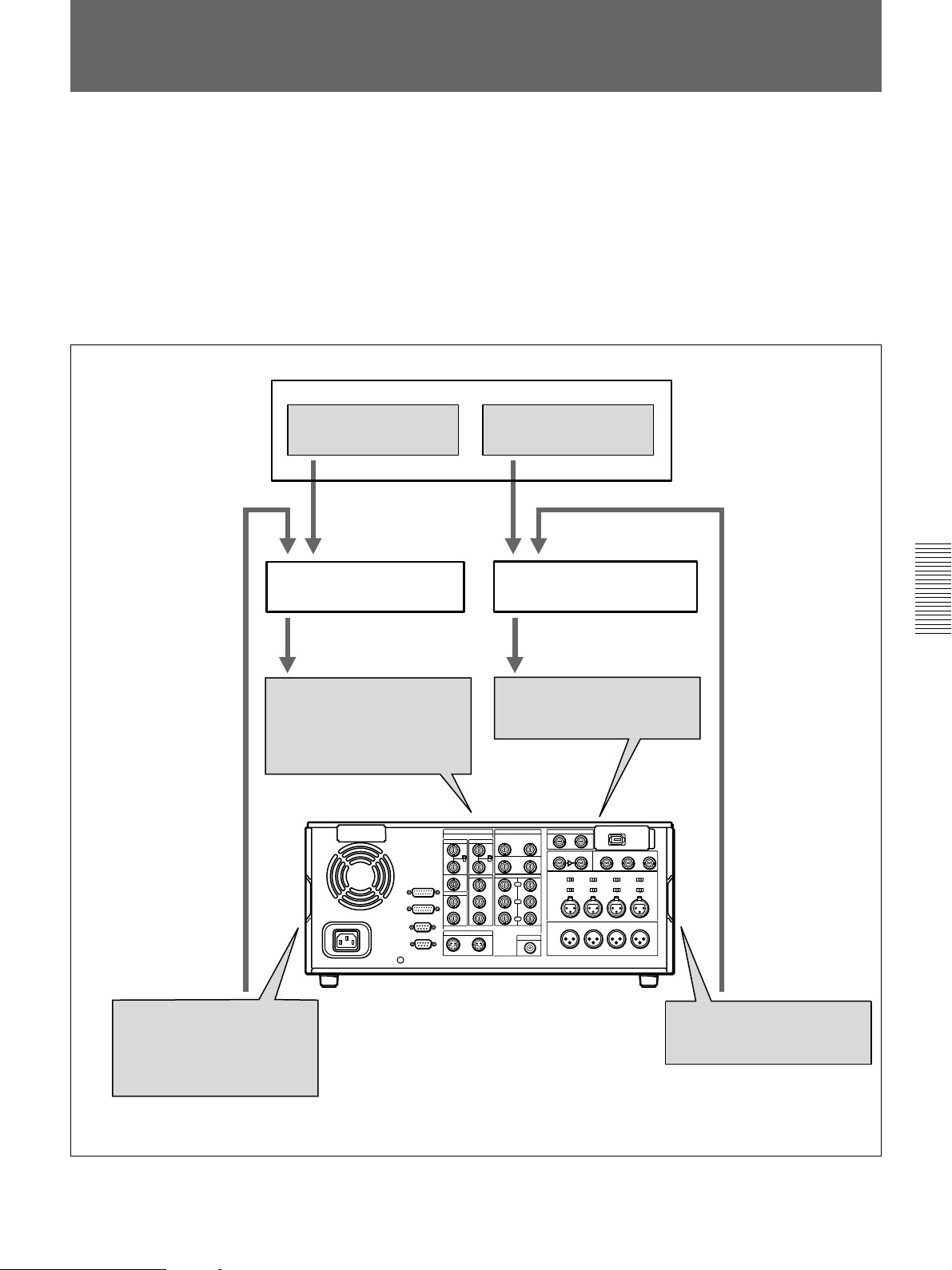
Preread Editing
Y
R-Y
B-Y
AUDIO OUT
DIGITAL AUDIO(AES/EBU) OUT
AUDIO IN
DIGITAL AUDIO(AES/EBU) IN
ANALOG VIDEO OUT
COMPONENT VIDEO OUT
S VIDEO OUT
SDI OUTPUT
ANALOG VIDEO IN
COMPONENT VIDEO IN
S VIDEO IN
SDI INPUT
Player
Video and audio signals already recorded on the recorder tape can be used
as an edit source for insert editing. This type of editing is called “preread
editing”, as the VCR uses the preread heads to read the signals in advance
from the tape.
The video signals read out by the preread heads can be sent to a video
switcher, and combined with video signals from the player for recording.
The audio signals read out by the preread heads can be sent to an audio
mixer for mixing with audio signals from the player for recording, and can
be recorded either on the original channels or on other audio channels.
Video source
Video switcher
Digital or analog video input
DSR-2000/2000P(recorder)
Audio source
Audio mixer
Digital or analog audio input
Chapter 4 Editing
Digital or analog video
output (preread signals)
Digital or analog audio
output (preread signals)
Chapter 4 Editing 87
Page 88
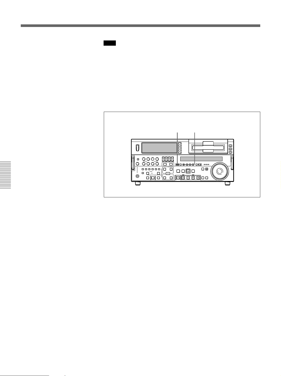
Preread Editing
Note
•You cannot carry out preread editing using SDTI or i.LINK signals.
•When the preread mode is selected (the PREREAD button is lit), to
prevent feedback in the loop connection, no E-E video out is available,
regardless of the operating mode of the unit. When preread mode is
turned off after preread editing, however, if the same channel remains
connected to both input and output, an E-E signal is output, and feedback
will occur. To prevent this, select PB mode as in step 1 of the following
procedure.
To carry out preread editing, use the following procedure.
2,6 1
Chapter 4 Editing
1 Press the PB button, turning it on.
2 Press the PREREAD button, turning it on.
3 Make the necessary connections for the preread editing. (See the
illustrations on the previous page and on page 129.)
4 After selecting the desired insert edit mode, carry out the preread
editing.
For details of how to select an edit mode, set edit points, etc., see Chapter 4
“Editing” (page 67).
5 When the preread editing is completed, remove the connections.
6 Press the PREREAD button, turning it off.
88 Chapter 4 Editing
Page 89

Special Editing Methods
This section describes the following editing methods.
•Quick editing
After selecting an edit mode, you can save on editing time by setting the
edit points and executing the edit at the same time.
•Continuous editing
When you execute multiple edits in succession, you can edit from the
second time on by setting the player IN and OUT points only.
•Standalone editing
You can carry out editing using as the player an external device, for
example a signal generator, which cannot be controlled remotely through
the REMOTE-IN or REMOTE-OUT connector.
•Manual editing
Without setting edit points in advance, you can carry out editing
manually while watching the monitor screen.
•Adding a narration (Sound-on-sound)
Using this unit alone, it is possible to carry out simple sound-on-sound
editing (such as adding a narration).
Chapter 4 Editing
Chapter 4 Editing 89
Page 90

Special Editing Methods
Quick Editing
After selecting an edit mode, you can save on editing time by setting the
edit points and executing the edit at the same time.
13
Chapter 4 Editing
5,7 2,486
1 Press the PLAYER button, turning it on.
2 Stop the tape on the player at the position you wish to make the IN
point.
3 Press the RECORDER button, turning it on.
4 Stop the tape on the recorder at the position you wish to make the IN
point.
5 Press the PREVIEW button.
A preview starts.
The tape positions determined in steps 2 and 4 are set as the player IN
point and recorder IN point, respectively.
6 Watching the editing on the monitor, at the position you wish to make
the OUT point, hold down the ENTRY/SHIFT button and press the
OUT button.
90 Chapter 4 Editing
Both the player OUT point and recorder OUT point are set.
7 Carry out another preview and modify the edit points as required.
For details of how to modify edit points, see the section “Modifying Edit
Points” (page 76).
Page 91

To edit even more quickly
8 Press the AUTO EDIT button.
The edit starts.
When the edit finishes, the recorder stops at the OUT point and the
player stops about 2 seconds after the OUT point.
By skipping the preview in the foregoing procedure, you can execute the
edit even more quickly. To do so, proceed as follows.
1 Perform steps 1 through 4 of the foregoing procedure.
2 Press the AUTO EDIT button.
The edit starts.
3 Watching the editing on the monitor, at the position you wish to make
the OUT point, hold down the ENTRY/SHIFT button and press the
OUT button.
The edit ends.
The point where the edit started is set as the IN point, and the point
where the edit ended is set as the OUT point.
Chapter 4 Editing
Continuous Editing
When you execute multiple edits in succession, you can edit from the
second time on by setting the player IN and OUT points only.
After execution of an edit, the recorder returns automatically to the OUT
point. Therefore, the recorder OUT point of the current edit becomes the
IN point of the next edit.
OUT point of previous edit =
Section edited in previous edit
Recorder
Player
IN point of next edit
Section edited in next edit
IN point
OUT point
Chapter 4 Editing 91
Page 92

Special Editing Methods
To carry out continuous editing, use the following procedure.
1
342
1 Press the PLAYER button, turning it on.
Chapter 4 Editing
2 Set the player IN and OUT points.
For details of how to set IN and OUT points, see the section “Setting Edit
Points” (page 72).
On the recorder, the OUT point for the previous edit becomes the new
IN point.
3 Press the PREVIEW button to carry out a preview.
4 Press the AUTO EDIT button.
The edit starts.
When the edit finishes, the recorder stops at the OUT point and the
player stops about 2 seconds after the OUT point.
To stop the edit
Press the ENTRY/SHIFT button together with the OUT button.
The edit ends, and the point where you pressed the buttons becomes
the OUT point.
To abort the edit
Press the STOP button.
92 Chapter 4 Editing
By repeating this process, you can carry out continuous editing.
With extended menu item 326, a setting can be made so that the preceding OUT
point automatically becomes the new IN point.
Page 93

Standalone Editing
This method allows you to use as the player an external device which
cannot be controlled remotely through the REMOTE-IN or REMOTEOUT connector. For example, you can record a color bar signal from a
signal generator in the joints between the scenes of an already completed
tape.
For standalone editing, use the following procedure.
12
43
1 In the input selection section, select the signal being generated by the
signal generator connected to the unit.
For details of the input selection section, see page 14.
2 Press both the PLAYER button and RECORDER button, turning them
off.
3 Set the IN point and, if necessary, also OUT point.
The AUTO EDIT button flashes.
For details of how to set IN and OUT points, see the section “Setting Edit
Points” (page 72).
4 Press the AUTO EDIT button.
The edit is carried out.
Chapter 4 Editing
Chapter 4 Editing 93
Page 94

Special Editing Methods
Manual Editing
To carry out manual editing, start playback on the player beforehand, then
use the following procedure.
4,6 1
3275
Chapter 4 Editing
1 Press the RECORDER button, turning it on.
2 Use the search dial in jog or shuttle mode to find the edit start point
(the recorder IN point), and stop the tape just before this point.
3 Select an edit mode.
For details of how to select an edit mode, see the section “Selecting an Edit
Mode” page 71.
4 Press the PLAY button.
The recorder begins playback.
Note
It takes about two seconds until the playback video stabilizes. For this
reason, start the playback from before the segment of video you wish
to use.
5 At the edit start point (the recorder IN point), press the EDIT button
and PLAY button simultaneously.
The edit starts.
94 Chapter 4 Editing
6 At the edit end point (the recorder OUT point), press the PLAY button.
The edit ends, and the recorder continues with playback.
7 Press the STOP button to stop the recorder playback.
Page 95

Adding a Narration (Sound-on-Sound)
By means of preread editing with an audio mixer connected (see page 87),
you can mix in an audio signal with the existing recorded soundtrack, but
extension menu item 819 provides a simple sound-on-sound editing
function for adding a narration, using this unit alone.
To add a narration from microphone input
As an example, the following procedure describes how to record a
narration mixed with audio channels 1 and 2 already recorded on the tape,
when the microphone is connected to input audio channel 1.
In this case, first connect the microphone to the AUDIO IN CH-1
connector, and set the audio input and editing mode as follows.
•In the input selection section (see page 14), with the CH1, 1/2 button,
select an analog audio signal.
•In the edit mode setting section (see page 20), press the INSERT CH-1
and CH-2 buttons, turning them on.
After checking the above settings, use the following procedure.
1 Set extension menu item 819 as follows.
Extension menu item 819 settings (on monitor screen)
ITEM-819
AUDIO INPUT SOURCE
in1 in2 in3 in4 tape
--------------------
on
ch1:
ch2:
on
ch3:
ch4:
Input channel numbers
ARRANGE
Recording channel numbers
on
on
For details of extension menu item 819 settings, see page 123.
2 Press the MIXING button in the upper control panel, turning it on.
3 Carry out insert editing on audio channels 1 and 2 (CH-1 and CH-2)
while reciting the narration into the microphone.
Chapter 4 Editing
Chapter 4 Editing 95
Page 96

Page 97

ClipLink Operation
Overview of ClipLink Operation
Chapter5
The ClipLink function provides the following.
• Displaying ClipLink log data
• Cueing up to Mark IN/OUT points and cue points
• Rewriting ClipLink log data (reel numbers, Mark IN/
OUT points, and OK/NG status only)
• Creating additional ClipLink log data and deleting
ClipLink log data (Mark IN/OUT points only)
• Automatically creating new ClipLink log data (Mark
IN/OUT points only)
When Mark IN/OUT points are created, the scene
number and take number for them are fixed at 000 and
00, respectively.
The above operations other than automatic creation of
new ClipLink log data require the ClipLink log data
list display.
Notes
• For a tape on which index pictures are already
recorded, you cannot change any ClipLink log data
other than the reel numbes and OK/NG status. (When
index pictures are recorded on a tape, the ClipLink
log data list for the tape shows an IP indication.)
• You cannot carry out ClipLink operation such as
“Continue” on the DSR-1/1P or DSR-300/300P/
500WS/500WSP for a tape whose ClipLink log data
has been modified on this unit.
For an overview of the ClipLink function, see the appendix “
ClipLink Guide” (page 147).
Chapter 5 ClipLink Operation
Chapter 5 ClipLink Operation 97
Page 98

Displaying ClipLink Log Data
To display ClipLink log data, hold down the ENTRY/
SHIFT button and press the LIST/– button.
LIST/– button
ENTRY/SHIFT button
The following ClipLink log data list appears in the
monitor.
Detailed Data Display
To check more details related to the data item selected
on the ClipLink log data list, proceed as follows.
21
1 Using the search dial, move the selection mark
(asterisk) to the data item for which you wish to
display details.
2 Press the SEARCH button.
CLIPLINK LOG DATA LIST
(003/196)
REEL NO XXXXXXXX
1 M 00:01:23:00 OK
2 M 00:02:35:00 OK
Chapter 5 ClipLink Operation
* 3 M 00:03:50:00 OK
4 M 00:04:03:00 OK
5 M 00:04:48:00 NG
6 M 00:04:53:00 OK
7 M 00:05:08:00 OK
8 I 00:06:13:00 IP
Mark IN/cue timecode
M = Mark IN point indication
C = cue point indication
I = Index picture address indication
OK/NG status or
IP (index picture)
indication
Data serial number
To return to the original monitor display
To exit from the ClipLink log data list and return to the
original monitor display, hold down the ENTRY/
SHIFT button and press the LIST/– button.
While you hold the search button down, the
detailed data display appears.
CLIPLINK LOG DATA LIST
(003/196)
MARK IN 00:03:50:00
MARK OUT 00:04:03:00
OK/NG OK
SCENE NO 001
TAKE NO 03
Mark IN point
display (cue point
and index picture
addresses not
displayed)
98 Chapter 5 ClipLink Operation
Page 99

Cuing Up to Mark IN/OUT and Cue Points
Cuing Up to Any Desired
Position
To cue up to the point specified by the data item
selected on the ClipLink log data list, proceed as
follows.
21
1 Using the SEARCH dial, move the selection mark
(asterisk) to the desired data item on the ClipLink
log data list.
When the selected data item display contains
“M” mark
The Mark IN point address is stored as the IN point
and the Mark OUT point address is stored as the
OUT point. At the same time, the IN button and
the OUT button on the control panel light.
Cuing Up to Adjacent Mark IN/
Cue Points
Once you select data on a ClipLink log data list, you
can cue up to the point preceding or following the
selected data with ease without reverting to the
ClipLink log data list.
F FWD button
REW button
MARK/+ button
To cue up to the Mark IN point or cue point
preceding the current point selected on the
list
Holding down the MARK/+ button, press the REW
button.
During the cue-up operation is in progress, the REW
button flashes.
Chapter 5 ClipLink Operation
When the selected data item display contains
“C” mark
The cue point address is stored as the IN point and
the IN button on the control panel lights.
2 Operate as follows.
•To cue up to the mark IN point or cue point
Holding down the IN button, press the PREROLL
button.
•To cue up to the mark OUT point
Holding down the OUT button, press the
PREROLL button.
This exits from the ClipLink log data list and cues
up to the selected position.
To cue up to the Mark IN point or cue point
following the current point selected on the list
Holding down the MARK/+ button, press the F FWD
button.
During the cue-up operation is in progress, the F FWD
button flashes.
Chapter 5 ClipLink Operation 99
Page 100
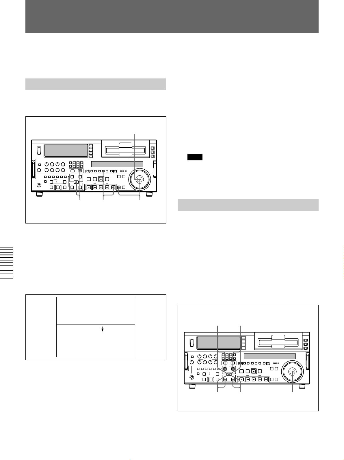
Rewriting ClipLink Log Data
You can rewrite the reel number, Mark IN/OUT points
and OK/NG status included in the ClipLink log data.
Changing the Reel Number
To change the reel number of the data item selected on
the ClipLink log data list, proceed as follows.
1,3
2,7
46
5 Repeat steps 3 and 4 until the settings for all digits
are complete.
6 When all digits have been set, hold down the
ENTRY/SHIFT button and press the MARK/+
button.
The reel number changes.
7 Hold down the STOP button and press the SET
button.
This returns to the original ClipLink log data list.
Note
If you carry out step 7 skipping step 6, the original
ClipLink log data list appears again on the monitor
and, in this case, the reel number is not rewritten.
Changing Mark IN/OUT Points
1 Using the search dial, move the selection mark
(asterisk) to the desired data item on the ClipLink
log data list.
2 Hold down the STOP button and press the SET
button.
Chapter 5 ClipLink Operation
The following setting screen appears.
CLIPLINK LOG DATA LIST
(003/196)
*REEL NO (XXXXXXXX)
REEL NO (YYYYYYYY)
3 Turn the search dial to select the digit to change.
Rotating the search dial clockwise moves the
current digit position to the right, and
counterclockwise moves it to the left.
To change Mark IN/OUT points selected on the
ClipLink log data list, perform the following
procedure.
When Mark IN/OUT points are rewritten to the
cassette memory, the frame digits of the address data
are processed as follows.
For Mark IN point: Any frame-digits value is
counted as 1 second.
For Mark OUT point: Any frame-digits value is
ignored.
82,7
1,3,564
4 Hold down the SEARCH button and turn the
search dial to change the digit indicated by an
arrow (µ).
100 Chapter 5 ClipLink Operation
 Loading...