

Page 1

Digital
Videocassette
Recorder
3-204-675-61(1)
Operating Instructions
Before operating the unit, please read this manual
thoroughly and retain it for future reference.
Note
The supplied CD-ROM includes Operating Instructions
for the DSR-series Digital Video Cassette Recorder or Player
(English, Japanese, French, German, Italian and Spanish
(DSR-1500A only) versions).
For more details, see “Using the CD-ROM Manual” on page 12.
DSR-1800/1800P
© 2000 Sony Corporation
Page 2

Owner’s Record
The model and serial num b ers are located at the rear.
Record these numbers in the spaces provided below. Refer
to them whenever you ca ll upon yo ur So ny de aler
regarding this product.
This symbol is intended to alert the user to
the presence of important operating and
maintenance (servicing) instructions in
the literature accompanying the
appliance.
Model No.
Serial No.
WARNING
To prevent fire or shock hazard, do not
expose the unit to rain or moisture.
To avoid electrical shock, do not open the
cabinet. Refer servicing to qualified
personnel only.
THIS APPARATUS MUST BE EARTHED.
CAUTION
The apparatus shall not be exposed to d ripping or
splashing and no objects filled with liquid, such as vases,
shall be placed on the apparatus.
The unit is not disconnected from the A C power source
(mains) as long as it is connected to the wall outlet, even if
the unit itself has been turned off.
WARNING: THIS WA R N ING IS APPLICA BLE FOR
USA ONLY.
Using this unit at a voltage other than 120 V ma y require
the use of a different line cord or attachment p lug, or both.
To reduce the risk of fire or electric sho ck, refer servicing
to qualified service personnel.
For customers in the US A (DSR -1800 on ly)
This equipment has b een tested and fo und to c omp ly with
the limits for a Class A digital device, pursuant to P art 15
of the FCC Rules. These limits are designed to provide
reasonable protection against harmful interference whe n
the equipment is operated in a com m e rcial environment.
This equipment generates, uses, and can ra diate radio
frequency energy and, if not installed and used in
accordance with the instruction manual, may cause
harmful interference to radio comm u nication s. Op eration
of this equipment in a residential area is likely to cause
harmful interference in which case the user will be
required to correct the interference at his own expense.
You are cautioned that any chang es or m odifications not
expressly approved in this manual could void yo ur
authority to operate this equipment.
The shielded interface cable recomm e nded in this m anua l
must be used w ith this equipment in o rder to co mply w ith
the limits for a digital device pursuant to Subpart B of Part
15 of FCC Rules.
Important Safety Instructions
• Read these instructions.
• Keep these instructions.
• Heed all warnings.
• Follow all instructions.
• Do not use this apparatus near water.
• Clean only with dry cloth.
• Do not block any ventilation openings.
This symbol is intended to alert the user to
the presence of uninsulated “dangerous
voltage” within the product’s enclosure
that may be of sufficient mag nitude to
constitute a risk of electric shock to
persons.
2
Install in accordance with the man ufacturer’s
instructions.
• Do not install near any heat sources such as radiators,
heat registers, stoves, or other apparatus (including
amplifiers) that produce heat.
Page 3

• Do not defeat the sa fety purpose of the po larized or
grounding-type plug. A polarized plug has two blade s
with one wider than the other. A grounding-type p lug
has two blades and a third grounding
prong. The wide blade or the third prong
are provided for your safety. If the
provided plug dose not fit into your outlet,
consult an electrician for replacement of
the obsolete outlet.
• Protect the power cord from being walked on or pinc hed
particularly at plugs, convenience receptacles, and the
point where they exit from the apparatus.
• Only use attachm ents/accessories spe cified by the
manufacturer.
• Use only w ith the cart, stand, tripod, bracket, or table
specified by the manufacturer, or sold w ith the
apparatus.
When a cart is used, use caution w h en moving the cart/
appa r a t u s combinati o n to avoid injury f rom tip - over.
• Unplug this apparatus d uring lightning storms or when
unused for long periods of time.
• Refer all servicing to qualified service personnel.
Servicing is required when the apparatus ha s been
damaged in any way, such as power-supply cord or plug
is damaged, liquid has been spilled or objects have fallen
into the apparatus, the apparatus has been exposed to
rain or moisture, does not operate normally, or has been
dropped.
Voor de Klanten in Nederlan d
• Dit apparaat bevat een vast ing ebouwd e batterij die niet
vervangen hoeft te word en tijdens de levensduur van het
apparaat.
• Raadpleeg uw leve rancier indien d e batterij toch
vervangen moet wo rden .
• De batterij mag alleen v ervang en worden door
vakbekwaam serviceperso neel.
• Gooi de batterij niet weg m a ar lever dez e in als klein
chemisch afval (KCA).
• Lever het apparaat aan het einde van de leve nsduu r in
voor recycling, de batterij zal dan op correcte wijze
verwerkt worden.
Caution
Television programs, films, video tapes and other
materials may be copyrighted.
Unauthorized recording of such material may be contrary
to the provisions of the copyright laws.
For customers in E urope (DS R-1800 P o nly)
This product with the CE marking com p lies with both the
EMC Directive (89 /336/E E C ) and the Low Voltage
Directive (73/23/EEC) issued by the C ommission of the
European Com munity.
Compliance with these directives implies conformity to
the following European standards:
• EN6006 5: Produ ct Safety
• EN5510 3-1: Electromagnetic Interference (Emission)
• EN5510 3-2: Electromagnetic Susceptibility (Immunity)
This product is intended for use in the following
Electromagnetic Environment(s):
E1 (residential), E2 (commercial and light industrial), E3
(urban outdoors) and E4 (controlled EMC environm ent,
ex. TV studio).
3
Page 4

AVERTISSEMENT
Afin d’éviter tout risque d’incendie ou d’électrocution, ne
pas exposer l’appareil à la pluie ou à l’humidité.
Afin d’écarter tout risque d’électrocution, garder le coffret
fermé. N e confier l’entretien de l’appareil qu’à un
personnel qualifié.
CET APPAREIL DOIT ÊTRE RELIÉ À LA TERRE.
Attention
Eviter d’exposer l’appareil à un égouttem ent ou à des
éclaboussures et ne placer aucun objet rempli de liquide,
comme un v ase, sur l’app areil.
Cet appareil n’est pas déconnecté de la source
d’alimentation secteur tant qu ’il est raccordé à la prise
murale, même si l’appareil lui-même a été mis hors
tension.
Des programm e s de télévision, films, bandes vidéo et
autres peuvent être protégés pa r des droits d’auteur.
L’enregistreme nt non autorisé de tels matériaux risque de
constituer une violation de ces droits d’auteur.
Pour les clients européens
(DSR-1800P seulement)
Ce produit portant la marque CE est conforme à la fo is à la
Directive sur la compatibilité électromagnétique (EMC )
(89/336/CEE) et à la Directive sur les b asses tensions
(73/23/CEE) ém ises par la C o m mission de la
Communauté européenne.
La conformité à ces directives implique la conformité aux
normes européennes suivantes:
• EN6006 5: Sécurité des produits
• EN5510 3-1: Interférences électromagnétiques
(émission)
• EN5510 3-2: Sen sibilité électromagn étique (immunité)
Ce produit est prévu pour être utilisé dans les
environnements électromag nétiques suivants:
E1 (résidentie l) , E 2 ( c ommercial et industri e légère),
E3 (urbain extérieur) et E4 (environnem ent EM C contrôlé
ex. stud i o d e télévision).
VORSICHT
Um Feuerg ef ahr und die Gefahr eines elektrischen
Schlages zu vermeiden, darf das Gerät weder Reg en noch
Feuchtigkeit ausgesetzt werden .
Um einen elektrischen Sc hlag zu vermeiden, darf das
Gehäuse nicht geöffnet werden. Überlassen Sie
Wartungsarbeiten stets nur qualifiziertem Fachpersonal.
DIESES GERÄT MUSS GEERDET WE RD E N .
Achtung
Das Gerät ist nicht tropf- und spritzwassersicher, daher
dürfen keine mit Flüssigkeiten gefüllten Gegenständ e,
z. B. Vasen, darauf abgestellt werden.
Solange das Netzkabel an eine N etzsteckdose
angeschlossen ist, bleibt das Gerät auch im
ausgeschalteten Zustand mit dem Stromnetz verbunden.
Für Kunde n in E u ro pa (N u r D S R -1 800 P )
Dieses Produkt besitzt die CE-Kennzeichnung und erfüllt
sowohl die EMV-Direktive (89/336/EEC) als auch die
Direktive Niederspannung (73/23/EEC) der
EG-Komm ission.
Die Erfüllung dieser Direktiven bedeutet Konformität für
die folgenden Europäischen Normen:
• EN6006 5: Produ ktsicherheit
• EN5510 3-1: Elek tromag netische Interferenz (Emission)
• EN5510 3-2: Elek tromag netische E mpfindlichkeit
(Immunität)
Dieses Produkt ist für den Einsatz un ter folgenden
elektromagnetischen Bedingungen ausge legt:
E1 (Wohnbe reich), E2 (kom merzieller und in
beschränktem Maße industrieller Bereich), E3
(Stadtbereich im Freien) und E4 (kontrollierter
EMV-Bereich , z.B. Fernsehstudio).
4
Page 5

ATTENZIONE
1. Für Ihren privat genutzten Videoreco der muß eine
Fernseh-Rundfunk-Gene hmigung beantragt
werden, sofern nicht bereits eine Gene hmigung für
ein Fernsehgerät desselben Haushaltes vorliegt. Im
geschäftlichen Bereich ist jeder einzelne
Videorecorder anmelde- und gebührenpflichtig.
(Auskunft ggf. bei der GEZ oder den
Rundfunkanstalten.)
2. Im privaten Bereich ist die Aufzeichnung von
urheberrechtlich geschützten Werken auf Bildund Tonträger gestattet. Die entsprechende n
Urheber-Vergütungen sind im Kaufpreis d es
Gerätes enthalten. Öffentliche Wiedergabe oder
Verbreitung von mitgeschnittenen
Fernsehsendungen ist ohne Erlaub nis nicht
zulässig, verpflichtet zu Schadenersatz und ist
gegebenenfalls strafbar.
3. Im Rahme n der R ege lung de s §47 des
Urheberrechtsgesetzes sind Aufzeichnu ngen von
Schulfernsehprogramm e n gestattet. M itschnitte
von Schulfunksendungen dürfen jedoch nur für
den Unterricht verwendet we rden un d sind
spätestens am E nde d es laufend en Sc huljahres zu
löschen.
Per evitare il pericolo di incendi o scosse e lettriche, non
esporre l’apparecchio alla pioggia o all’um idità.
Per evitare scosse elettriche, non aprire l’ap parecchio. Per
le riparazioni, rivolgersi solo a personale qualif icato.
QUESTO APPARECCHIO DEVE ESSERE MESSO A
TERRA.
Attenzione
L’apparec chio no n dev e essere esp osto a gocciolamenti o
spruzzi. Non collocare sull’apparecchio o ggetti contenenti
liquidi, come ad esempio vasi di fiori.
L’apparec chio no n è scollegato dalla fonte di
alimentazione CA (corren te di rete) fintanto che è
collegato ad una presa di corrente, anche se l’apparecch io
stesso è stato spento.
Programmi televisivi, film, videonastri e altro materiale
possono essere tutelati dai diritti d’autore.
Registrazioni non autorizzate di tali materiali possono
infrangere la legge sui diritti d’autore.
Per i clienti in Euro p a (DS R -1 800 P so ltan to )
Questo prodotto recante il marchio C E è co nforme sia alla
direttiva sulla compatibilità elettromagnetica (EMC)
(89/336/CEE) che alla direttiva sulle basse tensioni
(73/23/CEE) emesse dalla Comm issione della Comunità
Europea.
La conformità a queste direttive implica la conformità alle
seguenti normative europee:
• EN6006 5: Sicurezz a dei prod otti
• EN5510 3-1: Interferenza e lettromagnetica (Emissione)
• EN5510 3-2: Sen sibilità ai disturbi elettromagnetici
(Immunità)
Questo prodotto è destinato all’uso nei seguenti ambienti
elettromagnetici:
E1 (residenziali), E2 (comm erciali e industriali leggeri),
E3 (esterni urbani) e E4 (ambienti EMC controllati, ad
esempio studi televisivi).
5
Page 6

6
Page 7

Table of Contents
Chapter 1 Overview
Features........................................................................9
DVCAM Format .............................................................9
A Wealth of Interfaces..................................................10
Facilities for High-Efficiency Editing...........................10
Other Features...............................................................11
Optional Accessories.....................................................11
Using the CD-ROM Manual.......................................12
CD-ROM System Requirements...................................12
Preparations...................................................................12
To Read the CD-ROM Manual.....................................12
Location and Function of Parts................................13
Front Panel....................................................................13
Rear Panel .....................................................................21
Chapter 2 Recording and Playback
Usable Cassettes.......................................................27
Inserting and Ejecting Cassettes ...................................29
Recording...................................................................31
Settings for Recording ..................................................31
Recording Procedure.....................................................34
Playback.....................................................................37
Settings for Playback ....................................................37
Playback Procedure.......................................................38
Repeat Playback—Automatic Cyclical Playback .........40
Setting Points A and B for Repeat Playback.................40
Cuing Up to Any Desired Position Set as Point A or B45
Chapter 3 Convenient Functions for Editing Operation
Setting the Time Data................................................47
Displaying Time Data and Operation Mode Indications ..
47
Using the Internal Time Code Generator...................... 49
Synchronizing Internal and External Time Codes........51
Rerecording the Time Code—TC Insert Function........ 51
High-Speed and Low-Speed Search—Quickly and
Accurately Determining Editing Points ............54
Search Operations via External Equipment ..................54
Search Operations on This Unit....................................55
7
Page 8

Digitally Dubbing Signals in DVCAM Format..........56
Chapter 4 Menu Settings
Menu Organization....................................................59
Menu Contents...........................................................62
Setup Menu...................................................................62
Auto Mode (AUTO FUNCTION) Execution Menu.....75
Changing Menu Settings ..........................................76
Buttons Used to Change Settings..................................76
Changing the Settings of Basic Items...........................76
Displaying Enhanced Items ..........................................78
Changing the Settings of Enhanced Items ....................78
Returning Menu Settings to Their Factory Default
Settings ................................................................79
Displaying Supplementary Status Information.......80
Chapter 5 Connections and Settings
Connections for a Digital Non-Linear Editing System
83
Connections for a Cut Editing System....................85
Connections for an A/B Roll Editing System..........86
Connections for SDTI (QSDI) Dubbing....................92
Connections for Analog Recording.........................93
Adjusting the Sync and Subcarrier Phases............94
Chapter 6 Maintenance and Troubleshooting
Maintenance...............................................................97
Condensation.................................................................97
Regular Checks .............................................................97
Head Cleaning...............................................................99
Troubleshooting......................................................100
Error Messages............................................................ 102
Alarm Messages..........................................................102
Appendixes
Precautions..............................................................105
Specifications..........................................................106
ClipLink Guide.........................................................110
What Is ClipLink?.......................................................110
Example System Configuration and Operation Flow. 111
Data Generated When Shooting..................................112
Glossary...................................................................115
Index.........................................................................117
8
Page 9

Overview
Features
The DSR-1800/1800 P is a 1/4-inch digital video cassette
recorder using the DVCAM digital recording format. It
achieves stable, superb picture quality by digitally
processing video signals separated into color difference
signals and luminance signals (component method).
The unit is equipped with a v ariety of functions needed for
videocassette recorders and players used in professional
digital video editing systems. It supports the ClipLink
function developed by Sony Corporation fo r highly
efficient video editing. When connected to a Son y
EditStation
linear editing system*.
The unit is also equipped with a full-fledged analog
interface to support hybrid systems that combine
conventional analog equipment with digital equipment.
* Non-linear editing: This is an editing method that use s video and audio
signals di gitally encode d and re corde d on a h ard disk as di gital da ta. When
compared with conventional (linear) editing methods, non-linear editing
offers vastly improve d efficiency in editing operations, for example, by
eliminating tape transport time.
The main features of the unit are described in the
following.
TM
, the unit serves as part of a powerful non-
TM
Chapter
Because the recording is digital, multi-generation du bbing
can be performed w ith virtually no deterioration of quality.
Wide track pitch
The recording track pitch is 15 µm, fully 50 percent wider
than the 10-µm track pitch of the DV form at. Thanks to this
feature, the DVCA M format sufficiently meets the
reliability and precision requirements of professional
editing.
High-quality PCM digital audio
PCM recording m ak es for a wide dynamic range and a
high signal-to-noise ratio, thereby enhancing sound
quality.
There are two recording modes: 2-chann el mode (4 8-kHz
sampling and 16-bit quantization), which o ffers sound
quality equivalent to the DAT (D igital Au dio Ta pe)
format, or 4-channel mode (32-kHz sampling and 12-bit
quantization).
Playback compatibility with DV and
DVCPRO formats
A DV cassette recorded on a D V form at VCR as well as a
DVCPR O (25M) format recorde d cassette can be p layed
back on this unit.
1
DVCAM Format
DVCAM is based on the consumer DV format, which uses
the 4:1:1 component digital format, and provides a
digital recording format for professional use.
High picture quality, high stability
Video signals are separated into color difference signals
and luminance signals, which a re encoded and compressed
to one-fifth size before being recorded to ensure stable and
superb picture quality.
1
/4-inch
Note
When playing back a tape recorded in DVCPRO (25M)
format, the SDTI and i.LIN K outpu ts (see “D igital
interfaces” on page 10) of this unit are muted.
Furthermore, it is not possible to play back the cue-au dio
track of the tape.
Features
9
Page 10

Support for three cassette sizes
There are two sizes of D VCAM ca ssette: standard and
mini. You can use either size with this unit.
The unit also accepts L and M sizes of DV C PRO cassette.
• When a cassette is inserted, the reel mechanism of the
unit automatically adjusts to the size of the inserted
cassette.
• The capacity of a standard casse tte is 184 minutes of
Chapter 1 Overview
recording/playback, and that of a mini cassette is 40
minutes.
A Wealth of Interfaces
Digital interfaces
The following optional digital interfaces are available for
use with the unit.
SDTI (QSD I)* (op tional D S B K-1802 SDTI (Q S DI)
Input/Output Board): When the unit is fitted with the
optional DSBK -18 02 b oard, S D T I (Q S D I)-format
video, audio and time code signals can be transferred
between the unit and the Sony E ditStation at norm al
speed. When this unit is connected to another
DVCAM VCR, it is possible to copy compressed
signals between the two V CRs.
SDI (serial digital interface)/AES/EBU (op tiona l
DSBK-1801 SD I/AE S /EBU Input/Output Board):
When the unit is fitted with the optional DS B K-1801
board, it can input and output D1 (componen t) format
digital video and audio signals and also AE S/EB Uformat digital audio signals.
i.LINK (DV)** (o ptional D S B K-1803 i.LINK/D V
Input/Output Board): When the unit is fitted with the
optional DSBK-1803 board (i.LINK co mpatible), it
can input and output digital video and audio signals in
DV format.
* SDTI is the name of a standard inter f ace established as SMPTE 305M.
QSDI is a typ e of S DTI . This unit uses SDTI to t ran smit DV da ta , and th e
input/output connectors are labeled “SDTI (QSDI).”
** i.LINK and are trademarks and indi cate th at this pro duct is in agreem ent
with IEEE1394-1995 s pecifications and their revisions.
Analog interfaces
The unit also comes with analog interfaces enabling it to be
connected to analog video and audio equipm en t.
Analog video: These interfaces include a component
interface, composite interface, and S-video interface.
Analog audio: Four channels each of input and output are
provided. It is also possible to connect a microphone to
the unit.
Facilities for High-Efficiency Editing
The unit provides an abundance of functions that enhance
editing efficiency and precision.
Cross-fade editing
For audio editing, you can select from cut-in editing, fadein/fade-out editing, and cross-fade editing.
Support for ClipLink function
In response to comman ds sent from the EditStation, index
pictures recorded on tape or ClipLink log data recorded in
the cassette memory can be transferred to the E ditStation.
The EditStation operator can then efficiently use these
pictures and data in a preliminary editing session.
For an overview of the ClipLink function, see the appendix
“ClipLink Gu ide ” (page 110).
Internal time code generator and reader
An internal time code generator and rea der enab les time
code compliant with S MPT E (for DS R-1800)/EB U (D SR1800P) format to be recorded and play ed back. This allows
editing to single frame precision.
Outputting or inputting time code (L T C) to or from an
external device is also possible using the TIM E CO DE IN /
OUT connectors.
The unit is also compatible with V ITC.
Remote control
The unit can be operated by remote control from an editing
control unit that supports the RS-422A interface or from an
optional SIRCS*-compatible rem ote con trol unit such as
the DSRM-10.
* SIRCS (Sony Integrated Remote Control System): A command protocol
to remote control S on y prof essional videocas sette recorders/pla y ers.
Playback control using search dial
The search dial on the front pane l of the unit allows you to
carry out playback operation in jog or shuttle mode
without requiring an external editing control unit or remote
control unit to be connected to the unit.
High-speed search function
The unit has a picture search function that allows yo u to
view color picture at playback speeds up to 85 tim es
normal speed in forward and rev erse directions.
When remote-con trolling this unit in shuttle mode from an
editing control unit or a remote control unit, you can search
at any speed in the range 0 (still) to 60 times normal speed
in both directions. You can also search frame-by-frame in
jog mode.
10
Features
Page 11

At search speeds up to 10 times no rmal speed in both
directions, you can also hear playback audio.
Digital slow-motion playback
Using the frame me mory function, the unit can show
noise-free slow-motion playback at speeds ranging from 0
1
/2 times normal speed in both d irections.
to
Compatible with wide-screen aspect ratio
(16:9)
The unit can record and play back aspe ct ratio information.
When video accompanied by wide-screen aspect ratio
information is recorded or played back, the unit can output
the video signal also containing the aspect ratio
information.
Digital jog sound function
When searching at speeds in the ran g e + 1 to +1/30 or
1
/30 to −1* times norm a l speed, the digital jog sound
−
function is enabled. The audio signal is saved in temporary
memory, and replayed ac cording to the search speed. This
allows searching on the sound track.
* Th e positive direction refers to forward movement of the tape, and the
negative direction to reverse movement.
Video process control
For analog video output and SDI-format v ideo output, you
can adjust the video output level, chroma signal output
level, setup level (for DSR-1800), black level (for D SR1800P), and chroma phase.
Other Features
Menu system for functionality and
operation settings
The unit provides a menu system to make its various
functions easier to use and set up its operation conditions.
Rack mountable
When you use the op tional RM M-130 Rack M oun t K it,
you can mount this u nit onto an EIA-standard 19-inch rack
(height = 4 units).
Optional Accessories
DSBK-1801 SDI/AES/EBU Input/Output
Board
When installed in the unit, this optional board enables
digital video and audio signals in the D1 form a t and also
AES/EBU -form a t digital audio signals to be transferred
between this unit and digital Betacam V CRs or other
digital equipment.
DSBK-1802 SDTI (QSDI) Input/Output
Board
This interface allows video, audio and time code signals in
SDTI (QSDI) format to be transferred at norm al speed
between this unit and the Sony EditStation. When this unit
is connected to another DV C A M VCR , it is possible to
copy compressed signals betwee n the tw o VCRs.
Chapter 1 Overview
Superimposition function
Time code values, operation m ode indications, error
messages, and other text data can be superimposed and
output in analog composite video signals.
Easy maintenance functions
Self-diagnostic/alarm fun c tion: T h is function
auto matica l l y detects setu p and c o nnec t io n erro r s ,
operation faults, and other problems. It also displays a
description of the problem, its cause, and the
recommended response on the video monitor screen or
time counter display.
Digital hours meter: The digital hou rs m e ter function s
include four kinds of tally operations for operating
hours, head drum usage hours, tape transport hou rs,
and tape threading/unthreading times. The tally results
can be viewed on the video monitor or the time counter
display.
DSBK-1803 i.LINK/DV Input/Output Board
This board allows you to connec t the unit to other
equipment provided w ith a Sony DV connector to carry
out editing or dubbing of digital video and audio signals.
RMM-130 Rack Mount Kit
This kit can be used to mount the u nit onto an E IA standard 19-inch rack.
Features
11
Page 12

Using the CD-ROM Manual
The supplied CD-ROM includes O p erating Instructions
for the DSR-series Digital Video Cassette Recorder or
Player (English, Japanese, French, German, Italian and
Spanish (DSR-1500A only) versions).
Chapter 1 Overview
CD-ROM System Requirements
The following are required to acc ess the supp lied CDROM disc.
• Computer: PC with MM X Pentium 166 MHz or faster
CPU, or Macintosh co mputer with PowerPC CPU.
- Installed memory: 32 MB or more
- CD-RO M drive: × 8 or faster
• Monitor: Mon itor supporting resolution of 800 × 60 0 or
higher
When these requirem ents are n ot met, access to the CDROM disc may be slow, or not possible at all.
Preparations
The following software must be installed on your
computer in order to use the O perating In structions
contained in the CD-ROM disc.
• Microsoft Internet Explorer V ersion 4 .0 o r higher, or
Netscape Navigator V ersion 4.0 or high er
• Adobe A croba t Read er Version 4.0 or higher
Select and click the Operating Instructions that you
2
want to read.
A PDF file of the O perating Instructions o pens.
Note
If you lose the CD-RO M disc or become unable to read its
content, for example because of a hardware failure, contact
a Sony service representative.
• MMX and Pentium are registered trademarks of Int el Corporation or its
subsidiaries in the United States and other countries.
• PowerPC is a registered trademark of International Business Machines
Corporation.
• Macintosh is a registered trademark of Apple Computer, Inc.
• Microsoft is a registered trademark of M icrosoft Cor poration in t he United
States and/or other countries.
• Netscape Naviga tor is a registered trademark of Netscape
Communications Corporation in the U.S. and other countries.
• Adobe and Acrobat are registered trademarks of Adobe Systems
Incorporated in the United States and/or other countries.
Note
• If Microsoft Internet Explorer is not installed, it ma y be
downloaded from the following URL:
• http://www.microsoft.com/ie
• If Netscape Navigator is not installed, it may be
downloaded from the following URL:
• http://home.netscape.com/
• If Adobe A crobat Reader is not installed, it may be
downloaded from the following URL:
• http://www.adobe.com/products/acrobat/readstep.html
To Read the CD-ROM Manual
To read the Operating Instructions contained in the C DROM disc, do the following.
Insert the CD-ROM disc in your CD -R OM drive.
1
A cover page appears automatically in your browser.
If it does not appear automatically in the brow ser,
double click the index.htm file on the CD-ROM disc.
Using the CD-ROM Manual
12
Page 13
Location and Function of Parts
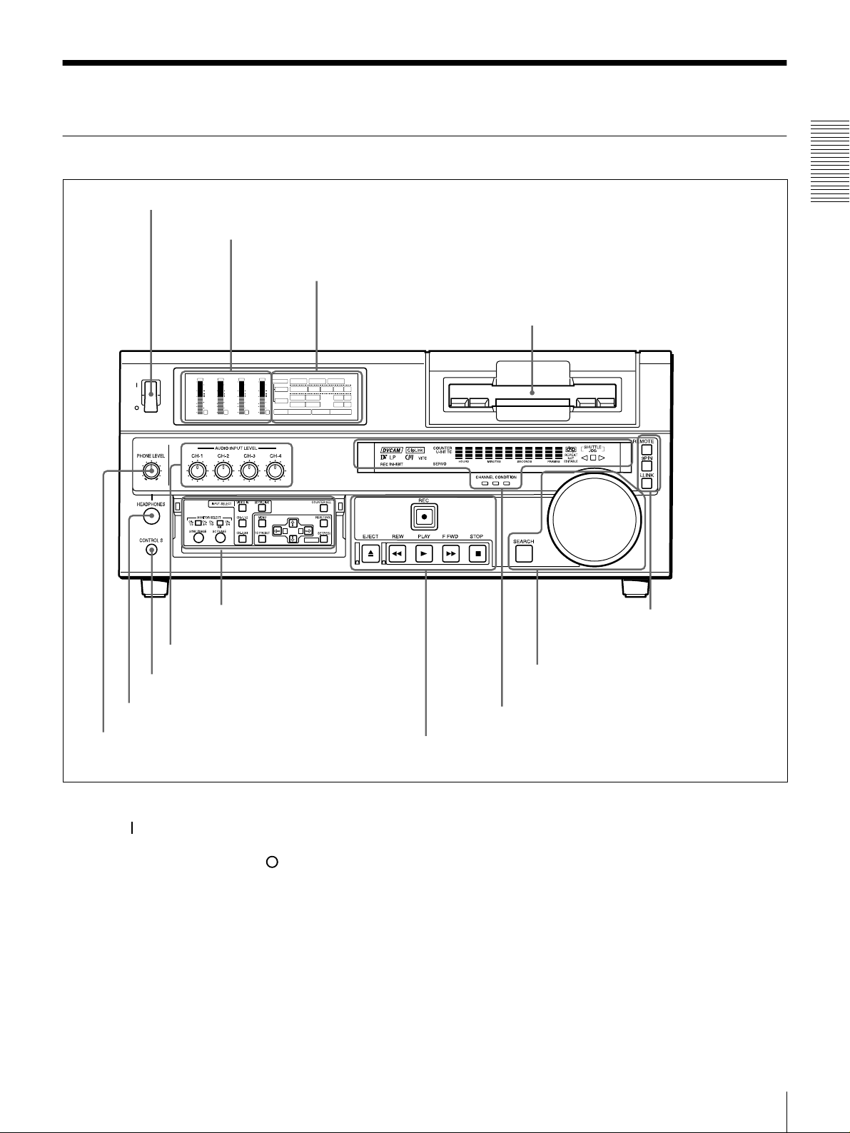
Front Panel
a POWER switch
POWER
OVER
dB
dB
dB
0
0
1
-12
-12
0
-20
-20
-1
-30
-30
-40
-40
-2
-60
-60
1
b Audio level meters
A Input selection/audio mode
display se c t ion
OVER
OVER
OVER
dB
dB
dB
dB
dB
INPUT
0
0
0
0
1
1
-12
0
0
-20
-1
-1
-30
-40
-2
-2
-60
2
3
V:SDTI SDTI i.LINK
0
0
COMPOSITE
Y-R,B
S VIDEO
MARK
AES/EBU
AES/EBU
REC MODE
2CH4CHPB FS
SDI SG
SDI SG
SDI SG
VIDEO
1
-12
CH11/2
0
-20
ANALOG
AUDIO
-1
-30
ANALOG
CH23/4
-40
-2
48k44.1k32k
-60
4
A B
B Menu control panel (inside of
the door)
(see page 15)
(see page 14)
c Cassette compartment
F Remote control setting
section
Chapter 1 Overview
(see page 20)
g AUDIO INPUT LEVEL control knobs
f CONTROL S connector
e HEADPHONES connector
d PHONE LEVEL control knob
a POWER switch
Press the “” side to power the unit on. When the unit is
powered on, the display windo w s in the front pan el lights.
To power the unit off, press the “” side of the switch.
b Audio level meters
These show the audio levels of channels 1 to 4 (recording
levels in recording mode or E-E m ode* and playback level
in playback mode).
* E-E mode: Abbreviation of “Electric-to-Electric mode.” In this mode,
video and audio signals input to the VCR are output after passing through
internal electric circuits, but not through magnetic conversion circuits such
as heads and tapes. This can be used to check input signals and for
adjusting input signal levels.
E Search control section
(see page 19)
D Display section
C Tape transport control section
(see page 18)
(see page 17)
c Cassette compartm ent
Accepts DVC A M, DV and D V C P R O (25M)
videocassettes.
For details of usable cassettes, see page 27.
d PHONE LE V EL control knob
Controls the volume of the headph ones c onnec ted to the
HEADPHONES connector.
Location and Function of Parts
13
Page 14
e HEAD PHONE S con n ecto r (stereo p hone jack)
Connect stereo headphones for headpho ne monitoring
during recording or playback.
The audio signal you w ant to monitor can be selected with
the MONIT O R SELEC T switches o n the m enu control
panel.
f CONTR OL S connector (stere o minijack)
Connect a SIRCS -com p atible rem o te co ntrol unit such as
Chapter 1 Overview
the DSRM-10.
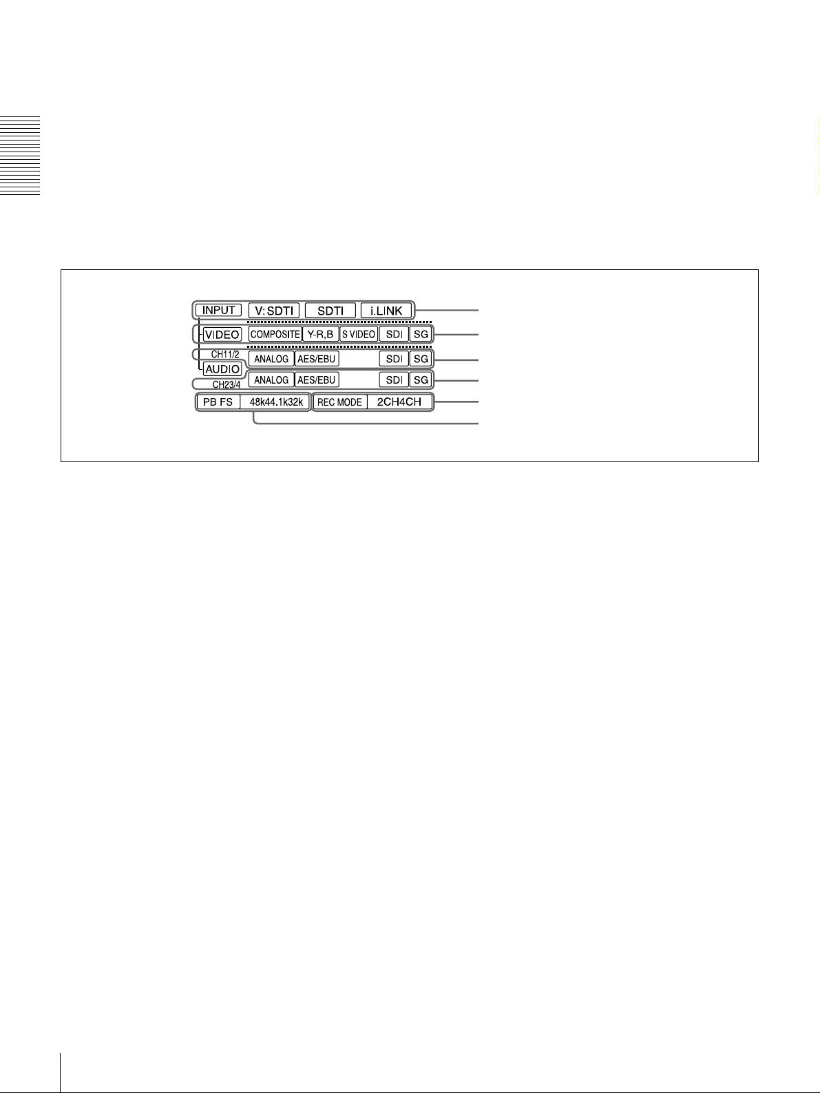
Input selection/audio mode display section
A
g AUDIO INPUT LEVEL control knobs
When recording, you can use these knobs to set audio input
levels for CH-1 (channel 1), CH-2, CH-3 and CH-4,
respectively.
You can mak e these k nobs ino perative w ith the RE C
LEVEL menu item (see page 70).
a INPUT display
b VIDEO display
c AUDIO CH1 1/2 display
d AUDIO CH2 3/4 display
e REC MODE display
f PB FS display
a INPUT d isplay
Indicates the input signal selected with the SDT I/i.LINK
butto n in the I NPUT SELECT sec t ion.
V:SDTI: Digital video signal in SDTI(QSDI) format
SDTI: Digital video and audio signals in SDTI(QSDI)
format
i.LINK: D igital video and aud io signals in i.LINK -
com patible DV f ormat
The SDTI/i.LINK b utton to func tion fully requires the
optional DSBK-1802 and 1803 boards to b e installed. The
signal without the corresponding optional board installed
in the unit can be neither selected nor indicated.
b VIDEO display
Indicates the input video signal selected with the VIDE O
IN button in the INPU T S ELECT section.
COMPOSITE: Composite video signal
Y−R, B: Y, R−Y and B−Y component video signals
S VIDEO: S-video signal
SDI: SDI video signal (optional DS BK-1801 board
required)
SG: Video test signal
c AUDIO CH1 1/2 display
Indicates the input audio signal selected with the CH-1,1/2
butto n in the I NPUT SELECT sec t ion.
ANALOG: Analog audio signal
AES/EBU: Digital audio signal in AES/EB U format
(optional DSBK-1801 board required)
SDI: SDI audio signal (optional DS BK-1801 board
required)
SG: Audio test signal
d AUDIO CH2 3/4 display
Indicates the input audio signal selected with the CH-2,3/4
butto n in th e I NPU T SELEC T sec t ion. The indicatio ns
available are the same as for the AUDIO CH1 1/2 display
described above.
e REC M O DE (audio recording mode) display
Indicates the audio recording mode (2C H or 4CH) selected
with the REC MODE menu item (see page 69).
f PB FS (playback audio sa mpling frequency)
display
Indicates the sampling frequency (48 kHz, 44.1 kHz or 32
kHz) at which audio is recorded on tape.
Location and Function of Parts
14
Page 15
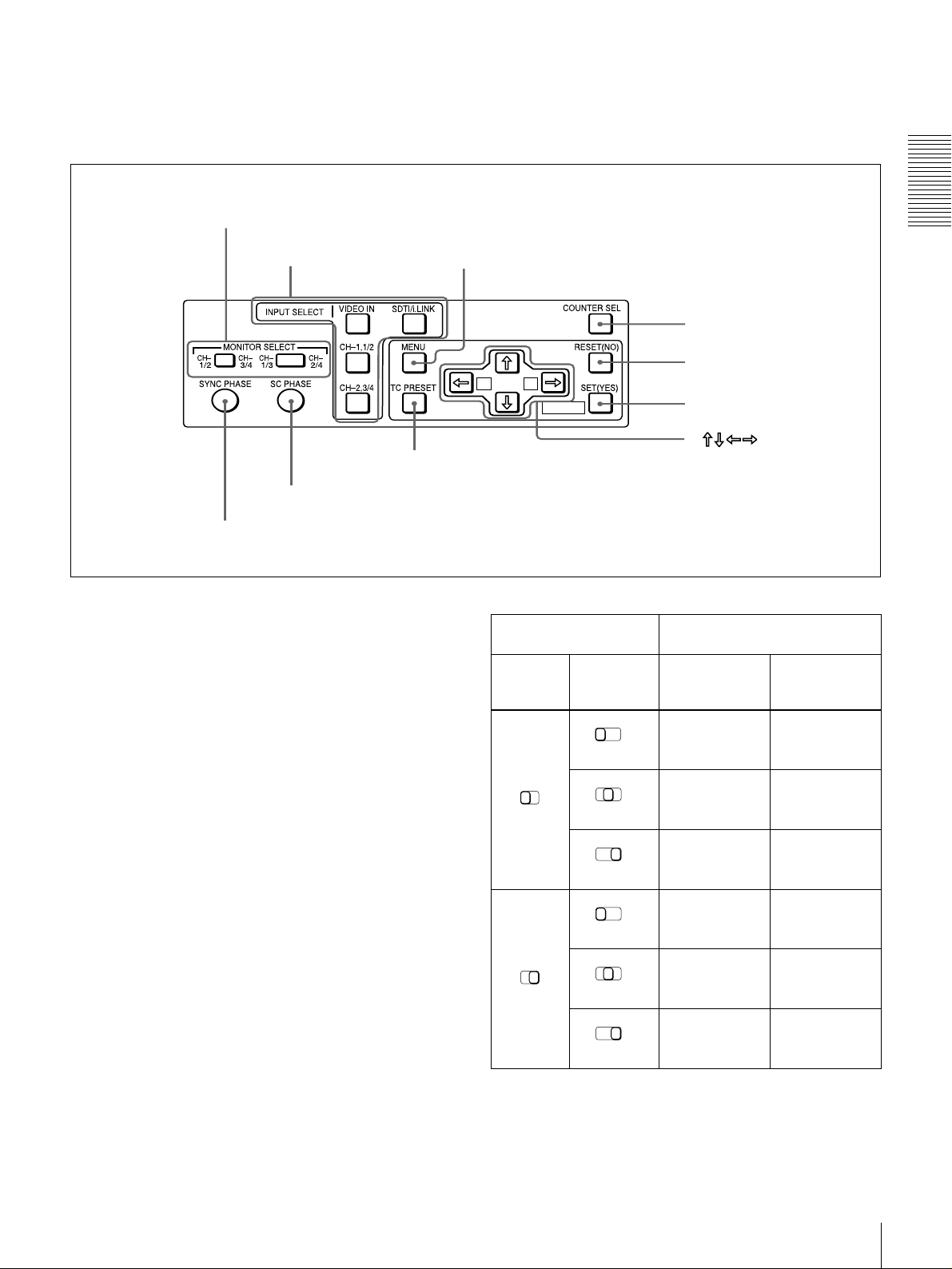
B Menu control panel
The menu control panel is located on the inside of the door
at the lower front of the unit. Pull the top of the door to
open it.
a MONITOR SELECT switches
b INPUT SELECT section
MIX
h TC PRESET button
i SC PHASE contro l
j SYNC PHASE control
a MONITOR SELECT switches
Use these switches to select the channels for audio output
via the AUDIO MONITO R OUT connector o n the rear
panel and the HEADPHONES connector on the front
panel.
Use the left switch to select the basic channel setting, then
use the right switch to select the output format (monaural,
stereo, or mix).
c MENU button
d COUNTER SEL button
e RESET (NO) button
A B
MARK
f SET (YES) button
g
buttons
Switch setting Selected channel and output
format
Left
switch
Right
switch
CH1/3
MIX
HEADPHONES
connector
Channel 1 only
CH2/4
(monaural)
Chapter 1 Overview
AUDIO
MONITOR OUT
connector
Channel 1 only
(monaural)
The following table lists the correspondence of left/right
switch settings and channel/output format selections.
CH1/2
CH1/2
CH-
CH-
1/3
3/4
CH3/4
MIX
CH-
1/3
MIX
CH-
1/3
MIX
CH-
1/3
MIX
CH-
1/3
MIX
Channels 1 and
CH-
2/4
2 (stereo)
Channel 2 only
CH-
2/4
(monaural)
Channel 3 only
CH-
2/4
(monaural)
Channels 3 and
CH-
2/4
4 (stereo)
Channel 4 only
CH-
2/4
(monaural)
Location and Function of Parts
Channels 1 and
2 (mix)
Channel 2 only
(monaural)
Channel 3 only
(monaural)
Channels 3 and
4 (mix)
Channel 4 only
(monaural)
15
Page 16

b INPUT SELECT section
VIDEO IN button
Each press of this button cycles through the following
input video signal selection options.
• Compo site video signal input to the VIDEO IN
connectors
• Component video signals input to the CO MPONE NT
VIDEO IN connectors
Chapter 1 Overview
• S-video signal input to the S VID EO IN connector
• SDI video sign al input to the SDI IN connector (op tional
DSBK-180 1 boa rd required)
• Video test signal (selected with the IN T VIDEO SG
menu item (see page 68) generated by the internal signal
generator
In the input selection/audio mode display section, the
VIDEO display show s the selection made w ith this button.
CH1,1/2 (audio channel 1 o r 1/2) bu tton
Each press of this button cycles through the following
input audio signal selection options for audio channel 1
(when in 2-channel mode) o r for audio chann els 1 and 2
(when in 4-channel mode).
• Analog audio signal(s) input to the A UDIO IN CH-1
connector (when in 2-channel mode) or AUDIO IN CH-
1 and CH-2 connectors (when in 4-channel mode )
• Digital audio signal in AE S/EB U format input to the
DIGITAL AUDIO (AES/EBU) IN CH-1/2 connector
(optional DSBK-1801 bo ard requ ired)
• SDI audio sign al input to the SDI IN connector (op tional
DSBK-180 1 boa rd required)
• Audio test signal (selected with the IN T AUDIO SG
menu item (see page 71) generated by the internal signal
generator
In the input selection/audio mode display section, the
AUDIO CH1 1/2 display shows the selection made with
this button.
When this is selected, use the CH1,1/2 button and
CH2,3/4 button to select the required input audio signals.
Note
In this case, the phases of the selected audio signals
will be about two frame s ahead of the ph ase of the
digital video signal in SDTI (QSDI) format.
• Digital video and audio signals in SDTI(QSDI) format
input to the SDTI(QSD I) IN connector (optional D SBK 1802 board required)
• Digital video and audio signals in i.LINK-compatible
DV format, input to the DV IN/OUT connector
(optional DSBK-1803 board requ ired)
In the input selection/audio mode display section, the
INPUT display show s the selection ma de with this button.
c MENU button
Press this button to display the menu on the monitor screen
and the time counter display. Press it again to return from
the menu display to the usual display.
On how to use the m en u, see C h apter 4 “Menu Settings.”
d COUNTER SEL (selection) button
Selects the type of time data to be show n in the time
counter display. Each press of this button cycles through
three indicator display options: COUNT ER (CNT: count
value of the time counter), TC (time c ode), and U -B IT
(user bits).
Note
When the RE MOTE bu tton in the rem ote control setting
section is lit, the COUNTE R SEL button do es not operate.
In this case, make the time data selection via the rem ote
equipment that is connected to the R EMOT E connector on
the rear panel.
CH2,3/4 (audio channel 2 o r 3/4) bu tton
Each press of this button cycles through the input audio
signal selection options for audio channel 2 (when in 2channel mode) or for audio chan nels 3 an d 4 (when in 4channel mode). The input au dio signal selection op tions
corresponding to those for the CH1,1/2 button described
above are available.
In the input selection/audio mode display section, the
AUDIO CH2 3/4 display shows the selection made with
this button.
SDTI/i.LINK (SDTI(QSDI) interface/i.LINK selection)
button
Each press of this button cycles through the following
input signal selection options.
• Digital video signal in SDTI(QSDI) form at input to the
SDTI(QSD I) IN connector (optional DSB K-180 2 board
required)
Location and Function of Parts
16
e RESET (N O) button
Pres s this bu t to n to:
• reset menu settings,
• reset the time count (COUNTER) shown in the time
counter display to zero, or
• send a negative respon se to the p rom pts issued by the
unit.
f SET (YES) button
Pres s this bu t to n to:
• save new settings, such as selected m enu items an d time
code settings, to the memory of the unit, or
• send a positive response to the prompts issued by the
unit.
g Arrow (JjKk) button s
Use these buttons to move around the menu items, and also
for setting time code and user bit data.
Page 17
For details on setting time code and user bit data, see
“Using the Internal Time Code Generator” on page 49.
h TC (time cod e) PRESET b utton
Use this button when setting an initial time code value and
user bit data.
For details on setting time code and user bit data, see
“Using the Internal Time Code Generator” on page 49.
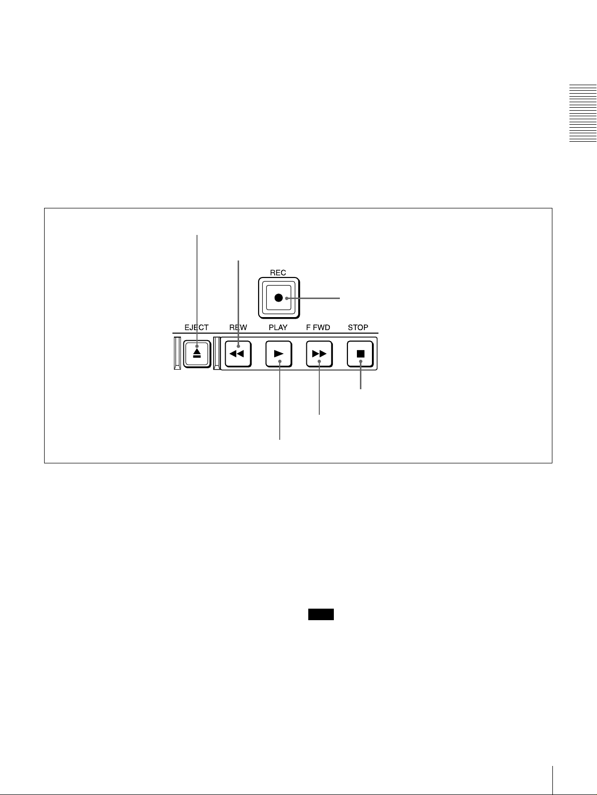
Tape transport control section
C
a EJECT button
b REW button
i SC (subcarrier) PHASE control
Turn this control to accurately adjust the subca rrier phase
of the composite video output signal of the unit w ith
respect to the reference video signal. Use a cross-point
(Phillips) screwdriver to turn it.
j SYNC (synch r onization) PHASE control
Turn this control to accurately adjust the synchronization
phase of the output video signal of the unit with respect to
the reference video signal. Use a cross-point (Phillips)
screwdriver to turn it.
c REC button
Chapter 1 Overview
d PLAY button
a EJECT button
When you press this b utton, it lights and the cassette is
automatically ejected after a few seconds.
b REW (rewind) button
When you press this b utton, it lights and the tape starts
rewinding (maximu m 85 tim es normal speed).
When the F. FWD /REW menu item (see page 63) is set to
PB, you can monitor the playback picture during the
rewind.
c REC (record) bu tton
When you press this button w hile holding down the PLA Y
button, it lights and recording begins.
d PLAY b utton
When you press this button, it lights and p layback be gins.
If you press this button during recording or editing, the
recording or editing operation is stopped and this unit
enters playback mode.
f STOP button
e F FWD button
e F FWD (fast forw ar d ) bu tton
When you p ress this button, it lights and the tape is fast
forwarded (maxim um 85 times norma l speed).
When the F. FWD /REW menu item (see page 63) is set to
PB, you can monitor the p layback picture during the fast
forward.
f STOP button
Press this button to stop the current tape transport
operation.
Note
No tape transport control buttons other than the EJE CT
and STOP buttons will work w hile the REMO TE button in
the remote control setting section is lit. This can be
changed with the LOCAL ENABLE menu item (see page
63).
Location and Function of Parts
17
Page 18

D Display section
Chapter 1 Overview
a Recording/playback format indicators
b ClipLink indicator
c VITC indicator
d Time data type indicators
e Time counter display
i CHANNEL CONDITION indicators
h SERVO indicator
g Cassette memory indicator
f REC INHIBIT indicator
j REPEAT indicator
a Recording/playback form a t indicators
DVCAM: This lights when a tape recorded in DV C AM
format is played back.
DV: This lights when a tape recorded in consumer D V
format is played back.
LP: This lights when a tape recorded in LP mode is played
back.
When a tape recorded in DVCPRO (25M) form at or any
other format than those mentioned abo ve is played back,
none of the above indicators lights.
k Tape end alarm indicator
l SHUTTLE/JOG indicators
m NOT EDITABLE indicator
Note
A tape recorded in LP m ode c annot b e played back
correctly. When a tape recorded in LP m o de is playe d
back, “DV LP” flashes and audio is muted.
b ClipLink ind icato r
Lights when a cassette is loaded on which ClipLink log
data is s t o r e d in the c assett e mem ory.
For details of ClipLink log data, see the appendix
“ClipLink Gu ide ” (page 110).
Location and Function of Parts
18
Page 19
c VITC indicator
Lights when VITC is being read or recorded regardless of
the data shown in the time counter display.
d Time data type indicators
One of the three indicators (CO UNTER, U-B IT , and T C )
lights to indicate the type of time data currently shown in
the time counter display.
COUNTER: Count value of the time counter
U-BIT: User bit data
TC: SMPTE time c ode (for DSR-180 0) or EBU tim e code
(for DSR-1800P)
e Time counter display
Indicates the count value of the time counter, time c ode,
VITC, or user bit data depending on the se ttings of the
COUNT ER SEL button on the m enu control panel and the
TC SELECT menu item (see page 66).
Also used to display error messages and setup menu data.
f REC (recording) INHIBIT ind icator
Lights in the following cases:
• The RE C /SAVE switch on the loade d cassette is in the
SAVE position.
• The REC INH IBIT m enu item (see page 6 3) is set to
ON.
l SHUTTLE/JOG indicators
When searching in shuttle mode using the search dial, the
SHUTTLE in dicator ligh t s , and when s e a r c hing in jog
mode using the search dial, the JOG indicator lights. When
the search dial is turned clockwise causing playback to
take place in the forward direction, the G ind ic a to r lig ht s .
When the search dial is turned counterclock wise causing
playback to take place in the reverse direction, the g
indicator lights. When the tape is stopped, the s indicator
lights.
For more information a bout the sea rch d ial, see “Search
dial” in the next section.
m NOT EDITABLE indicator
Lights during playback of a tape that contains a recording
in other than the DVC A M format. Whe n this indicator is
lit, the recordings contained in the tape can be used as
source material for editing, but editing operations such as
insert editing and assemble editing cannot be performed.
This indicator also lights when the audio reco rding m o d e
selected on this unit does not coincide with that of the
loaded tape.
E Search control section
Chapter 1 Overview
g Cassette memory indicator
Lights when a cassette provided with a memory chip
(“cassette memory”) is loaded.
h SERVO indicator
This indicator lights when the drum servo a nd cap stan
servo are locked*.
* Servo lock: This refer s to the synchronizati on of the phase of the drum
rotation a nd the ref eren ce sign al for the ta pe t ran sp ort posi tion , so t ha t th e
video heads can trace the same pattern on the tape for playback and
recording.
i CHANNEL CONDITION indicators
These three-color indicators show the state of the playback
signal.
Green: The state of the playback sign al is good.
Yellow: The playback signal is somew hat deteriorated, but
playback is possible.
Red: The playback signal is deteriorated. When the red
indicator remains on, head cleaning or an internal
inspection is necessary.
j REPEAT indicator
This indicator lights when the REP EAT MODE menu item
(see page 62) is set to ON .
k Tape end alarm indicator
Starts flashing when the remaining c apacity of the tap e is
for about 2 minutes.
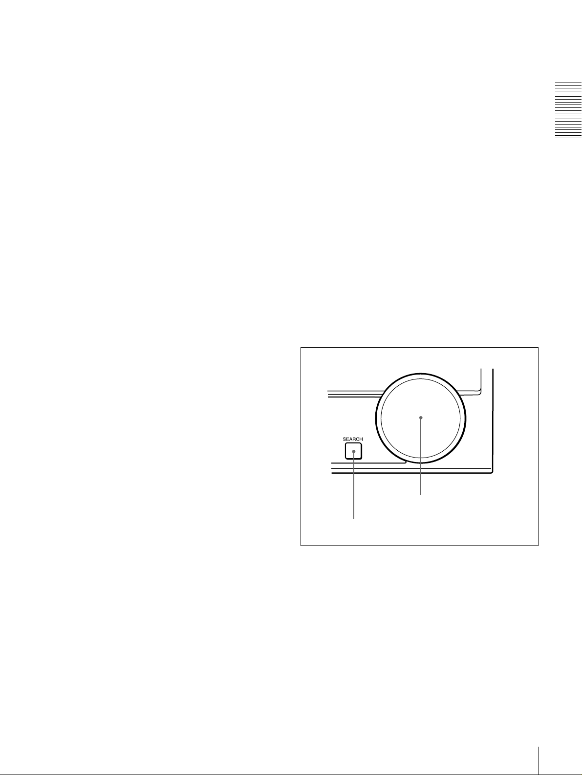
b Search dial
a SEARCH button
a SEARCH button
To use the search dial for playba ck in shuttle or jog mo de,
press this button, turning it on. Pressing the dial toggles
between shuttle and jog modes. In shuttle mode, the
SHUTTL E ind icator in the display section lights, and in
jog mode, the JOG ind icator in the display section lights.
b Search dial
Turn this to carry out playback in the modes show n in the
following table. Turning the dial clockwise lights the G
indicator in the display section and plays back in the
forward direction. Turning the dial counterclockwise
lights the g indicator in the display section and plays back
Location and Function of Parts
19
Page 20
in the reverse direction. When the tape is stopped , the s
indicator in the display section lights.
Pressing this dial toggles playback between shuttle mo de
and jog mode. Wh en p laying bac k in shuttle mode, the
SHUTTL E ind icator in the display section lights, and
when playing back in jog mode, the JOG indicator lights.
You can carry out noiseless playback in the range of ±
times normal speed.
Chapter 1 Overview
Playback mod es using the search dial
Playback mode Operation and functions
Shuttle Press the SEARCH button or the search
Jog Press the SEARCH button or the search
dial so that the SHUTTLE indicator in
the display section lights, then turn the
search dial.
Playback is carried out at a speed
determined by the posi tion o f t he se arch
dial. The maximum shuttle mode
playbac k speed can be cha nged with the
SHUTTLE menu item
dial so that the JOG indicator in the
display section lights, then turn the
search dial. Playback is carried out at a
speed determined by the speed of
rotation of the sea rch dial. The pla y ba ck
speed is up to
factory default.
The search dial has no detents.
(see page 63)
±1 times n ormal speed b y
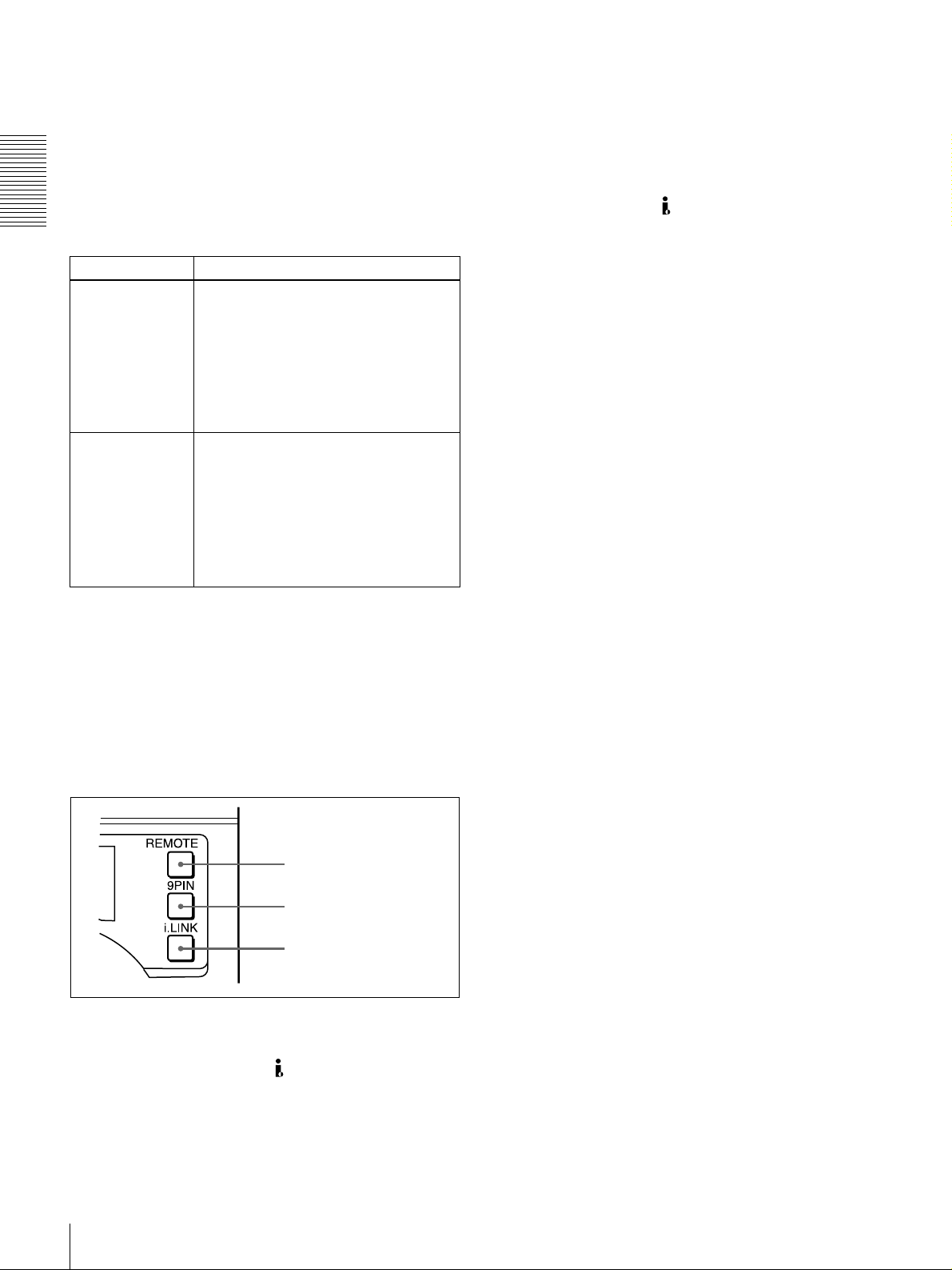
b 9PIN button
When carrying ou t remo te control between this unit and
the unit connected to the REMOTE conn ector, press this
button, turning it on.
1
/2
c i.LINK button
When carrying ou t remo te control between this unit and
the unit connected to the DV IN/OU T co nnector, press
this button, turning it on. This requires the optional DSBK1803 board to be installed.
.
You can use the SEARC H ENAB LE menu item (see pa ge
63) to select either of the following as the operation to be
performed to put the unit into search mode (shuttle or jog).
• Either press the SEAR C H button or, except during
recording/editing, turn the search dial (factory default
setting).
• Press the SEAR C H button.
F Remote control setting section
a REMOTE button
b 9PIN button
c i.LINK button
a REMO T E button
When remote-con trolling this unit from the unit connected
to the REMO TE connector or DV IN/OU T co nnec tor,
press this button, turning it on.
When reverting to local mod e to use the buttons in the tape
transport control section, press this button again, turning it
off.
Location and Function of Parts
20
Page 21
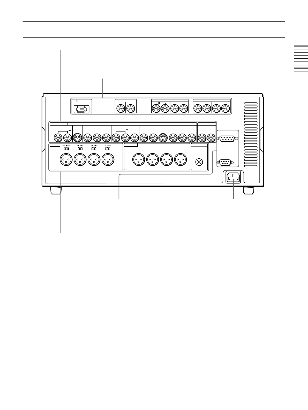
Rear Panel
A Analog video signal input/output section
B Digital signal input/output section
B-Y
LEVEL
HIGH
600
ON
Ω
SDTI(QSDI)
IN
REF.VIDEO
OUT
OUT
CH-1
DV IN/OUT
ANALOG VIDEO
VIDEO IN VIDEO OUT
LEVEL
LOW
AUDIO IN AUDIO OUT
OFF
CH-1
S VIDEO
IN
LEVEL
HIGH
LOW
OFF
ON
600
Ω
CH-2 CH-3
COMPONENT VIDEO IN
R-Y
Y
LEVEL
HIGH
HIGH
LOW
LOW
OFF
ON
600
Ω
OFF
ON
600
Ω
CH-4
(see page 22)
IN
S VIDEO
(SUPER)
CH-2 CH-3
(see page 23)
SDI
OUT
COMPONENT VIDEO OUT
Y
OUTIN 1 2
CH-4
R-Y
DIGITAL AUDIO(AES/EBU)
CH-3/4 CH-3/4
CH-1/2
IN
TIME CODE
IN
B-Y
MONITOR OUT
AUDIO
OUT
OUT
Chapter 1 Overview
CH-1/2
VIDEO CONTROL
REMOTE
~AC IN
D External device connectors
C Analog audio signal input/output section
AC IN con nector
Use the supplied power cord to co nnect this to an A C
outlet.
(see page 24)
(see page 25)
AC IN connector
Location and Function of Parts
21
Page 22
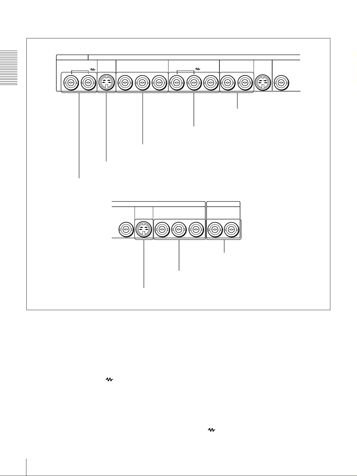
A Analog video signal input/output section
ANALOG VIDEO
VIDEO IN VIDEO OUT
Chapter 1 Overview
a VIDEO IN connectors
S VIDEO
COMPONENT VIDEO IN REF.VIDEO
IN
b S VIDEO IN connector
VIDEO OUT
R-Y
B-Y
c COMPONENT VIDEO IN Y/R
S VIDEO
2
COMPONENT VIDEO OUT
OUT IN
Y
OUT
d REF. VIDEO IN/OUT connectors
−
Y/B−Y connectors
TIME CODE
R-Y
B-Y
OUT
e VIDEO OUT 1 and 2 (SUPER)
S VIDEO
(SUPER)
connectors
OUTIN 1 2
YY
f S VIDEO OUT connector
a VIDEO IN connectors (BNC type)
Input an analog composite video signal. This con nector
block has a built-in automatic 75 Ω termination switch.
When a signal is input to the left VIDE O IN c onnec tor
with no bridging (loop-through) connection m ad e, the
connector is terminated with an im peda nce of 7 5 Ω
automatically. To connect the signal input to the left
VIDEO IN connector also to other equipment, use the right
VIDEO IN connector (marked ). When the right
VIDEO IN connector is used, the built-in 75 Ω termina tion
switch turns off automatically.
b S VIDEO IN connector (4-p in)
Input an S-video signal with sep arated Y (lumina nce) and
C (chroma: 3.58 MH z for DSR-1800 or 4.43 MHz for
DSR-1800P) components to this connector.
h TIME CODE IN/OUT connectors
g COMPONENT VIDEO OUT Y/R
−
Y/B−Y connectors
c COMPONENT VIDEO IN Y/R−Y/B−Y connectors
(BNC type )
Input analog component video signals (Y/R −Y/B−Y) to
these connectors.
d REF. (reference) VIDEO IN/O U T connectors
(BNC typ e)
Input a reference video signal. The IN connector block has
a built-in automatic 75 Ω termination switch. When a
signal is input to the left REF. VIDEO IN connector with
no bridging (loop-through) connection made, the
connector is terminated with an im peda nce o f 75 Ω
automatically. To connect the reference video signal input
to the left REF. VIDEO IN connector also to other
equipment, use the right REF. VID E O IN connector
(marked ). When the right REF. VIDEO IN conne ctor
Location and Function of Parts
22
Page 23
is used, the built-in 75 Ω term ination switch turns off
automati cally.
The REF. VIDEO OU T c onnec tor outputs a reference
video signal, except when i.LINK is selected in the IN PUT
g COMPONENT VIDEO OUT Y/R−Y/B−Y
connectors (BNC type)
These connectors output analog com p onent vide o signals
(Y/R−Y/B−Y).
SELECT section (see page 16).
h TIME CODE IN/OUT connectors (BNC type)
e VIDEO OUT 1 and 2 (SUPER) connectors (BNC
type)
These connectors output analog com po site video signals.
When the CHARA. DISPLAY menu item (see page 65) is
set to ON (factory default setting), connector 2 (SUPER)
outputs a signal with superimposed text informa tion.
Input SMPTE time co de (for DSR-1800) or E BU time
code (for DSR-180 0P) ex ternally generated to the IN
connector.
The OUT conn ector outputs a time co de acc ording to the
operating state of the unit, as follows:
During playback: the playback time code
During recording: the time code gen erated by the internal
f S VIDEO OUT conn ector (4-pin)
This connector outputs an S-video signal w ith separated Y
(luminance) and C (chrom a : 3.58 MHz for DSR -1800 or
time code generator or the time code inp u t to the T IME
CODE IN con n ector. When the EE OU T P HASE menu
item (see page 67) is set to MUTE , no time code is output.
4.43 MHz for DS R-1 800P ) components.
B Digital signal input/output section (optional DSBK-1801/1802/1803 boards required)
Chapter 1 Overview
SDTI(QSDI)
IN
IN
DV IN/OUT
OUT
SDI
OUT
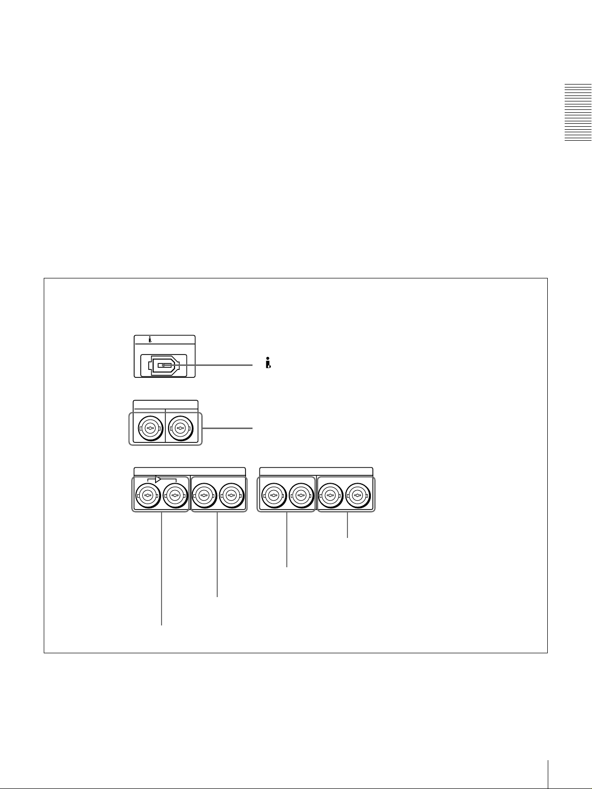
d SDI OUT connectors
a DV IN/OUT connector
b SDTI (QSDI) IN/OUT connectors
DIGITAL AUDIO(AES/EBU)
CH-3/4 CH-3/4
CH-1/2
IN
e DIGITAL AUDIO (AES/EBU) IN connectors
CH-1/2
OUT
f DIGITAL AUDIO (AES/EBU) OUT connectors
c SDI IN and active through output connectors
Location and Function of Parts
23
Page 24
a DV IN/OUT connector (6-pin IEEE-1394)
(optional DSBK -1803 i.LIN K /DV Input/Output
Board required)
This i.LINK-com patible connector (subsequently referred
to also as the i.DV IN/OUT co nnector) inputs and outputs
digital video and audio signals in DV format.
Note
When searching at speeds in the ran ge +1/2 to +1/30 or
Chapter 1 Overview
1
/2 to −1/30 times normal speed, the audio signal output
−
from this connector and m onitored on externa l equipm ent
may sound differently from the audio signal played back
on th is unit.
c SDI (Serial Digital Interface) IN (input) and active
through output connectors (BN C ty pe) (optional
DSBK-1801 SD I/AES/EBU Input/Output Boar d
required)
Input digital video and audio signals in SDI form at to the
left-hand connector. The right-hand connector is for an
active-through connection.
d SDI (Serial Digital Interface) O U T connectors
(BNC type) (op tional D S B K-1801 SDI/AE S /E BU
Input/Output Board requ ired)
Output SDI-format digital video an d audio signals. The
same signals are output from both con n ectors.
b SDTI (QSDI) (Serial Data T ransport Interface
(QSDI)) IN /O U T connectors (B N C type) (optional
DSBK-1802 SDTI (Q S D I) In p u t/O u tpu t B oard
required)
The IN connector inputs and the OUT connector outpu ts
digital video and audio signals in SDTI (QS D I) forma t.
Note
When searching at speeds in the ran ge +1/2 to +1/30 or
1
/2 to −1/30 times normal speed, the audio signal outpu t
−
from this connector and m onitored on externa l equipm ent
may sound differently from the audio signal played back
on th is unit.
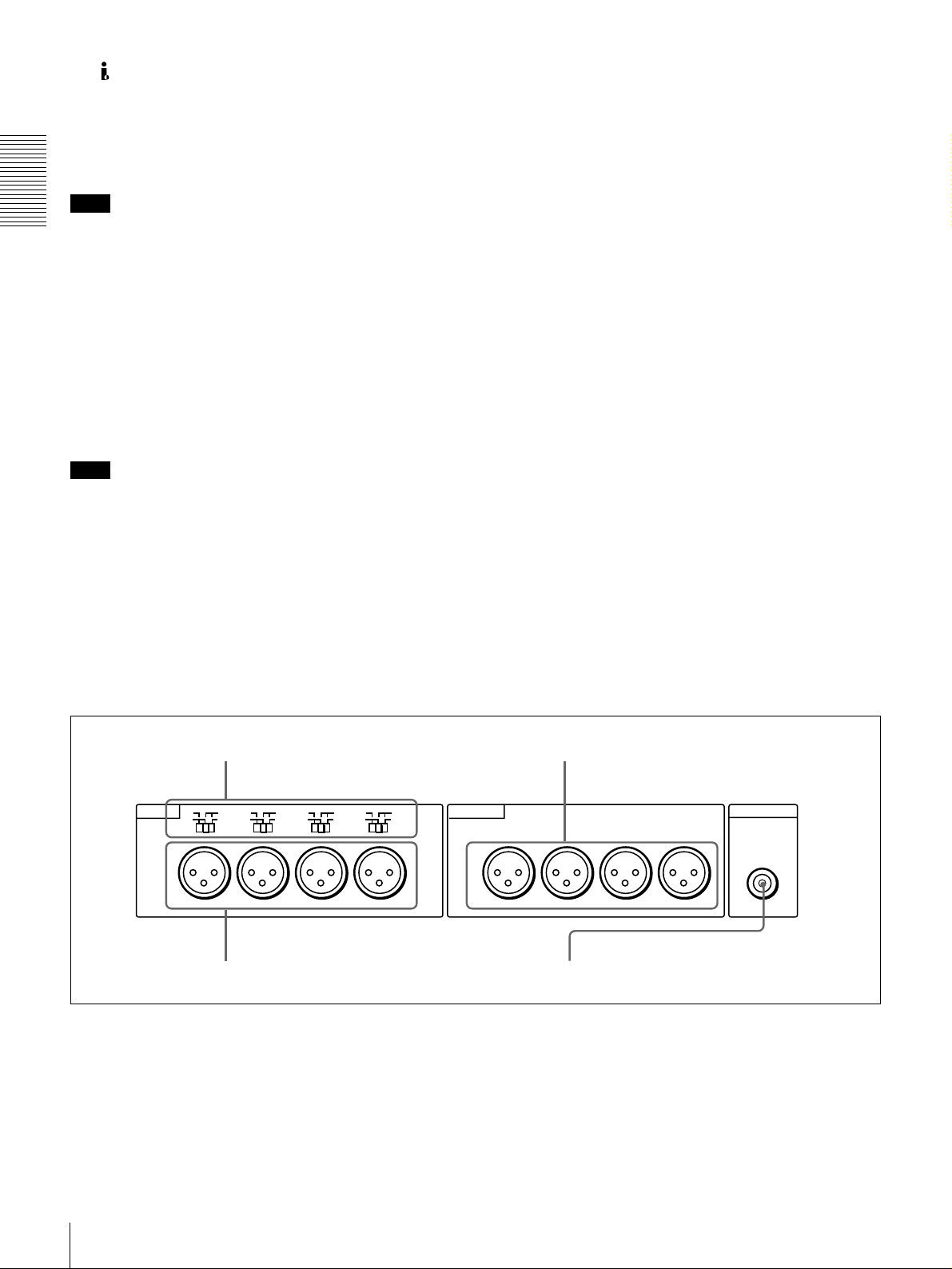
C Analog audio signal input/output section
a AUDIO IN LEVEL/600 Ω switches
e DIGITAL AUDIO (AES/EBU) IN connectors
(BNC type) (op tional D S B K-1801 SDI/AE S /E BU
Input/Output Board requ ired)
Input digital audio signals in AES/EB U form a t to these
connectors.
The left-hand connector (CH-1/2) is for aud io chan nels 1
and 2, and the right-hand connector (CH -3/4) is for audio
channels 3 and 4.
f DIGITAL AUDIO (AES/EBU) OUT connectors
(BNC type) (op tional D S B K-1801 SDI/AE S /E BU
Input/Output Board requ ired)
These connectors output digital audio signals in AE S/EBU
format.
The left-hand connector (CH-1/2) is for aud io chan nels 1
and 2, and the right-hand connector (CH -3/4) is for audio
channels 3 and 4.
c AUDIO OUT CH-1 to CH-4 connectors
LEVEL
LOW
AUDIO IN AUDIO OUT
OFF
CH-1
LEVEL
HIGH
LOW
OFF
ON
600
Ω
CH-2 CH-3
b AUDIO IN CH-1 to CH-4 connectors
600
HIGH
LEVEL
LOW
OFF
ON
Ω
600
HIGH
ON
Ω
CH-4
LEVEL
LOW
OFF
a AUDIO IN LEVEL/600 ΩΩΩΩ switches
Set these switches for each channel as shown in the
following table, according to the audio input levels to the
AUDIO IN CH-1 to CH-4 connectors and the required
impedance.
Location and Function of Parts
24
600
HIGH
ON
Ω
CH-1
CH-2 CH-3
d AUDIO MONITOR OUT connector
CH-4
MONITOR OUT
AUDIO
Page 25
Settings of the AUDIO IN LEVEL/600 ΩΩΩΩ switches
Audio input Switch setting
Level Impedance
−−−−60 dBu
(microphone input)
+4/0/−3
(line audio input)
+4/0/−3
(line audio input)
a) Selectable on DSR-1800P only
a)
/−−−−6 dBu
a)
/−−−−6 dBm
High impedance
(about 20 kΩ)
High impedance
(about 20 kΩ)
600 Ω HIGH-ON
LOW-OFF
(left position)
HIGH-OFF
(middle
position)
(right position)
b AUDIO IN CH-1 (channel 1) to CH-4 connectors
(XLR 3-pin, female)
Use these connectors to connect separate channe ls of
analog audio input from a player VCR or other external
audio equipment.
You can switch the audio input level setting with the
LEVEL SELECT menu item (see page 71).
c AUDIO OUT CH-1 (channel 1) to CH-4 connectors
(XLR 3-pin, male)
These connectors output channel-1 to ch annel-4 an alog
audio signals, respectively.
It is possible to use the AUDIO OUT CH-3 and AUDIO
OUT CH-4 connectors for audio mon itor output for
channels 1 and 2, respectively (use the OUTPUT C H3 /4
menu item (see page 71)).
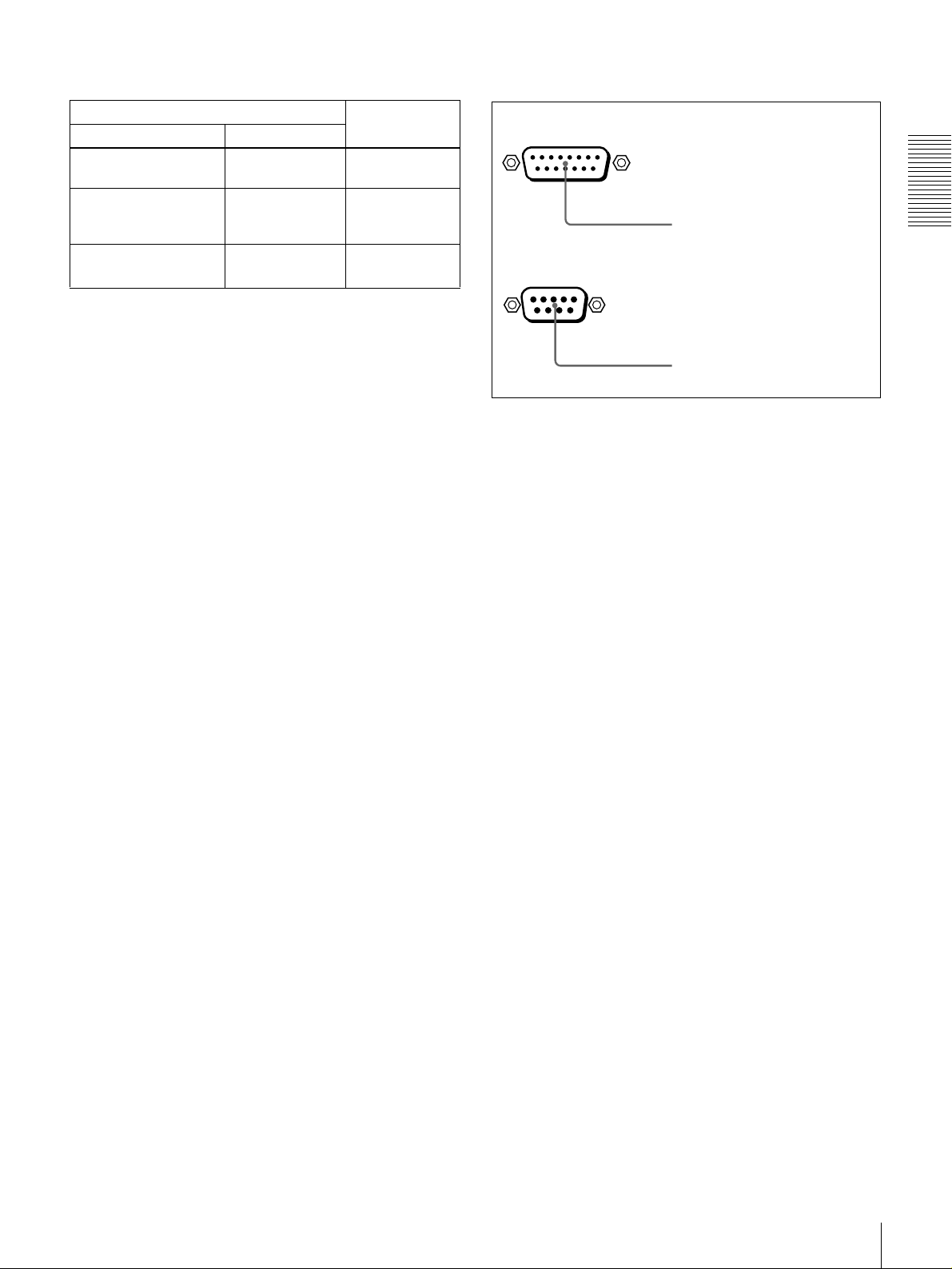
D External device connectors
VIDEO CONTROL
a VIDEO CONTROL connector
REMOTE
b REMOTE connector
a VIDEO CONTROL connector (D-sub 15-pin)
For remote control of the internal digital video processo r,
connect an optional remote control unit such as the U V R 60/60P or BVR-50/50P to this connector.
b REMOTE connector (D-sub 9-pin)
When controlling this unit from an editing con trol unit
such as the ES-3, ES-7, PVE-500, BV E -600/800 /910/
2000, or RM-450/450CE , connect the u n it to the editing
control unit via this connector using the optional 9-pin
remote control cable.
Chapter 1 Overview
d AUDIO MONITOR OUT connector (RCA phono
jack)
This connector outputs audio signals for monitoring. The
audio signals to be output from this connector can be
selected with the MONITOR SE LECT switches o n the
menu control panel.
Location and Function of Parts
25
Page 26

Chapter 1 Overview
Location and Function of Parts
26
Page 27

Recording and Playback
Usable Cassettes
This unit can use the DV C AM cassettes listed below.
Model name Size
PDV-64ME/94ME/124ME/184ME Standard size
PDVM-12ME/22ME/32ME/40ME Mini size
The numbers in each model name ind icate the m aximum recording/playback
time (in minutes) for each m odel. F or exa mple, the PDV-184M E has a
maximum recording/play back time of 184 minutes.
Cassettes usable fo r playback only
All consumer D V cassettes and large- and medium-size DV CPRO (25M )
cassettes are usable for playback only.
Notes
• If you insert an incorrect type of cassette, it will be automatically ejected.
• When opera ting this unit as a player, you can also use DV cassettes on the
unit. However, it is the best choice to always use DV CA M cassettes because
they are more reliable than DV cassettes w hatever your purpose may be:
playback, editing, or long-period storage of recordings.
• Cassettes that have been recorde d by a DV-format recorder can be played
back on this unit but cannot be used for recording at editing operation. When
you insert such a cassette into this unit, the NOT EDITAB LE indicator lights
up in the display section on the front panel of this unit.
Chapter
2
Usable Cassettes
27
Page 28
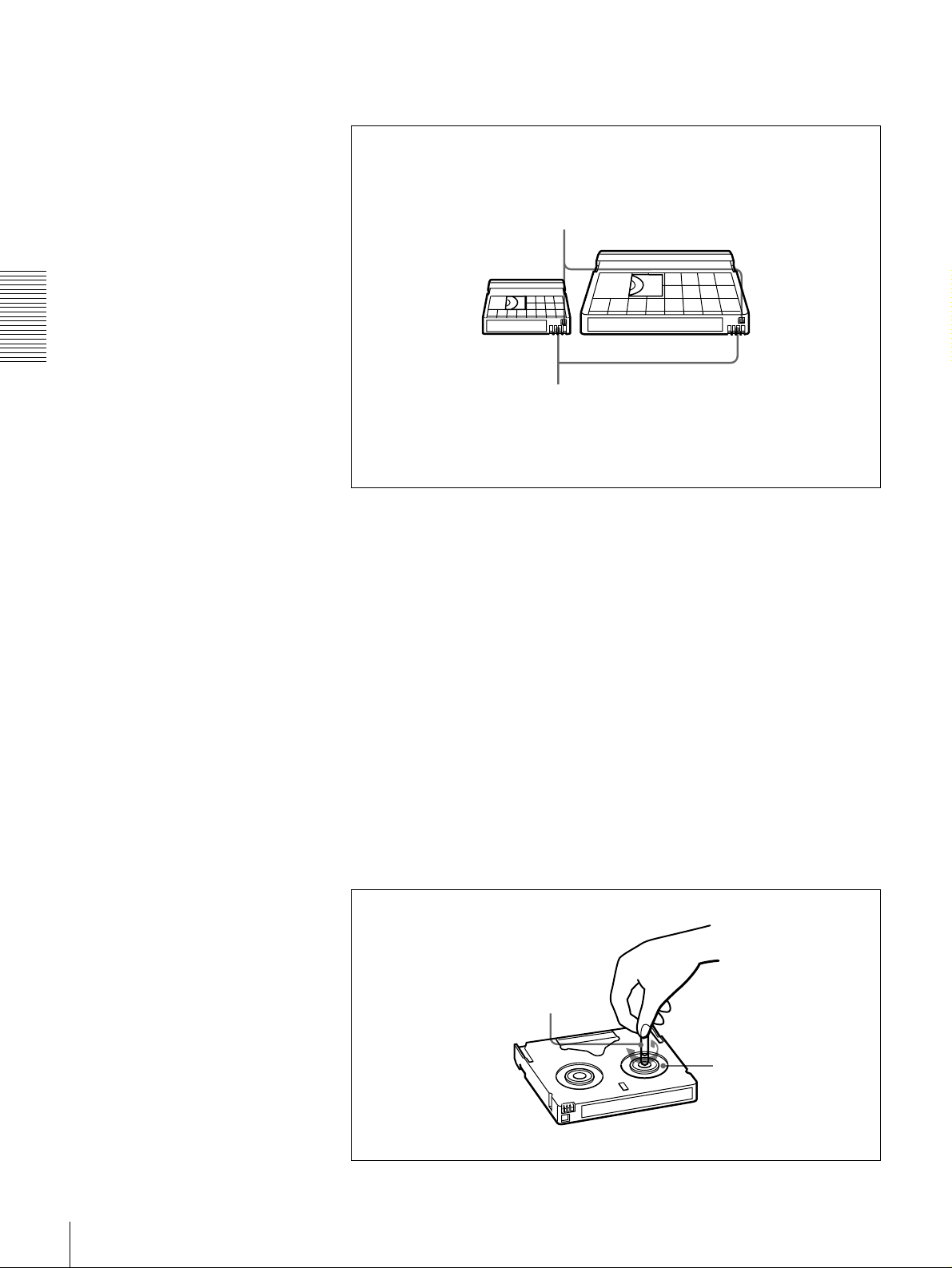
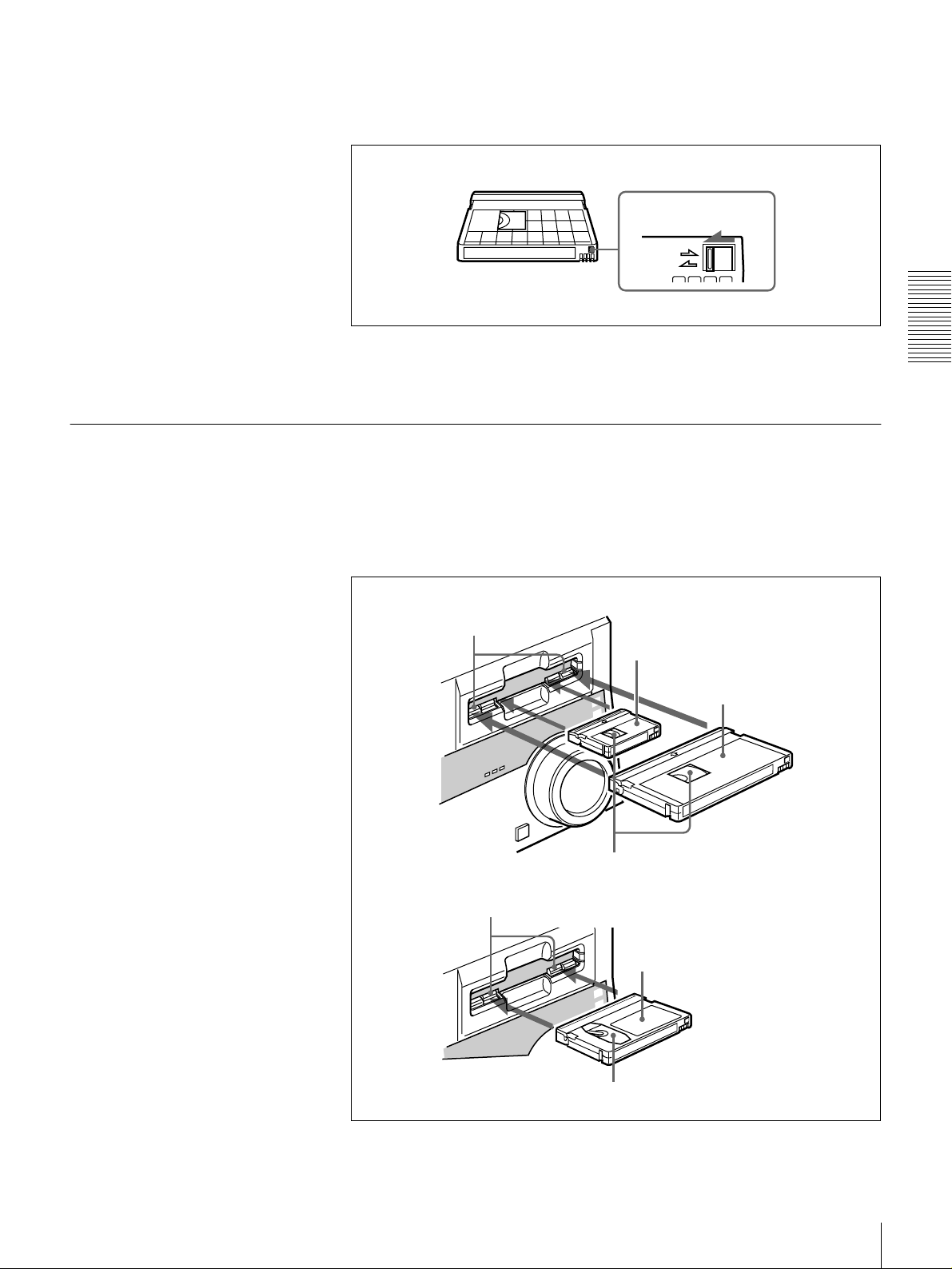
DVCAM cassettes
Chapter 2 Recording and Playback
Notes on using cassettes
The following f i g ure ill u strates the D VCAM casse tt e s .
REC/SAVE switch
For details of this switch, see “Preventing accidental
erasure” on page 29
Mini size Standard size
Cassette memory
This memory is used to store ClipLink log data.
For details of ClipLink log data, see the appendix
“ClipLink Guide”(page 110).
• Before storing the cassette for a long period of time , rewind the tape to the
beginning and be sure to put the c assette in its storage case, preferably on end
instead of flat on its side.
Storing a cassette in any other condition (not rewound, out of its case, etc.)
may cause the video and audio c ontents to bec ome damaged over tim e.
• If the cassette memory co nnector (contact point) becomes dirty, connection
problems may occur, causing a loss of functions. Remove away any d ust or
dirt from this area before using the cassette.
• If the cassette is dropped on the floor or otherwise receives a hard impa ct, the
tape may become slackened and may not record and /or play back correctly.
Checking the tape for slack
For information about how to check the tape for slack , see the next section.
Using a paper clip or a similar object, turn the reel gently in the direction shown
by the arrow. If the reel does not mov e, there is no slack. Insert the cassette into
the cassette compartment, and after abo u t 10 sec onds tak e it out.
Paper clip, etc.
Reel
28
Usable Cassettes
Page 29
Preventing accidental erasure
Set the REC/SA VE switch on the cassette to SA V E to preven t accidental
erasure of recorded contents.
To enable re-recording
Set the REC/SAVE switch to REC.
When this switch is set to SAVE, the unit cannot record o n the tape .
Inserting and Ejecting Cassettes
Inserting a cassette
This unit accepts three sizes of cassette: L (standard size), M (medium size:
DVCPR O) and S (mini size). When inserting a cassette in the unit, make sure
its tape window faces upward as show n in the following figure.
REC/SAVE switch
Set to SAVE
REC
SAVE
Chapter 2 Recording and Playback
Outer guides
Inner guides
Mini size (Insert the cassette into the
middle of the cassette compartment.)
Standard size
Tape window facing upward
Medium size (Align the cassette with
the outer guides, then slide it in over
the inner guides.)
Tape window facing upward
Usable Cassettes
29
Page 30
No double insertion of cassettes
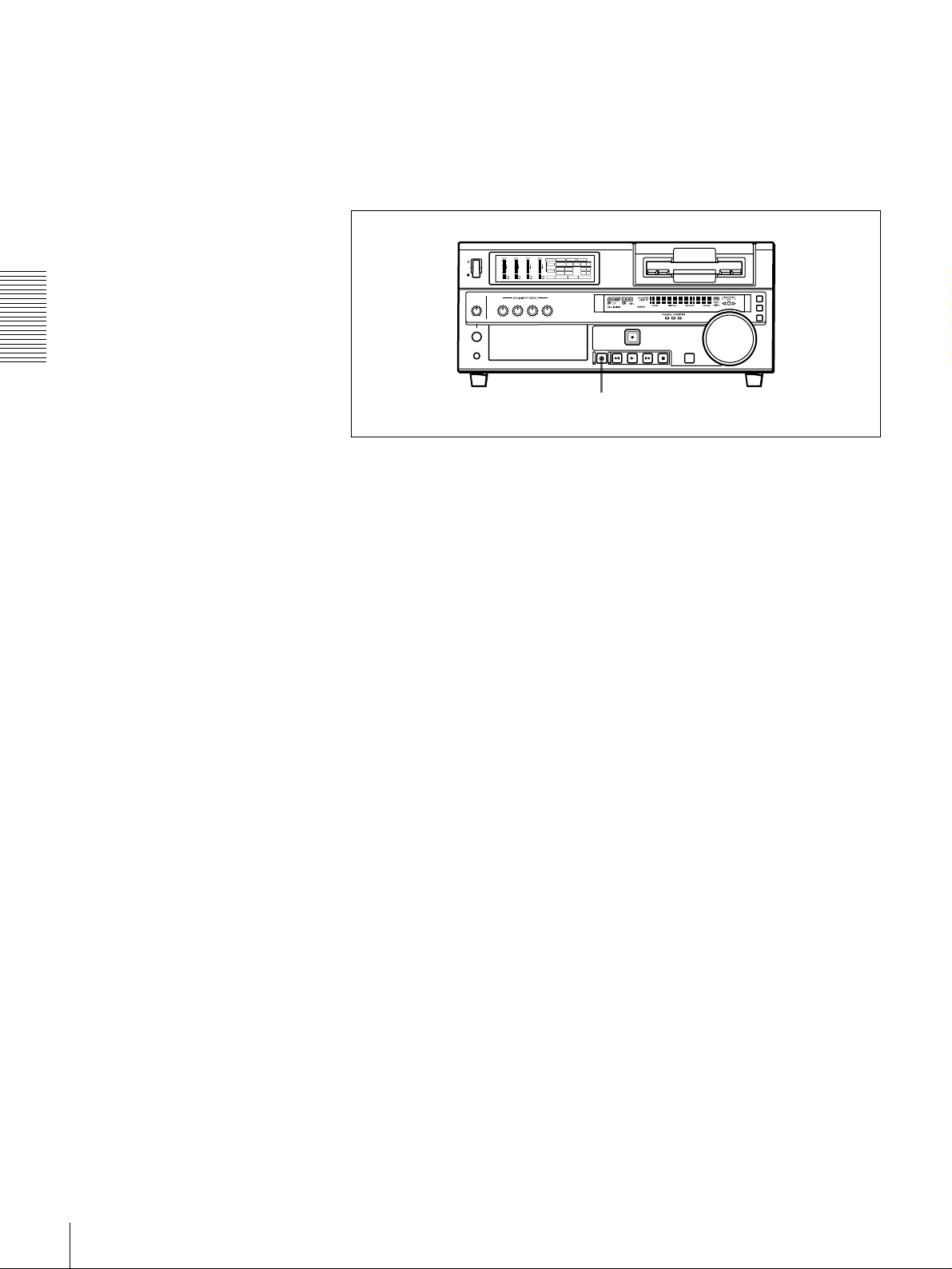
Ejecting a cassette
Chapter 2 Recording and Playback
When you insert a cassette, the orange lock-o ut plate appea rs in the cassette
compartment to prev ent dou ble insertion.
Press the EJECT button.
OVER
OVER
OVER
OVER
dB
dB
dB
dB
dB
dB
dB
dB
INPUT
0
0
-12
1
-20
0
-1
-30
-40
-2
-60
1
V:SDTI SDTI i.LINK
0
0
0
0
0
0
S VIDEO
SDI SG
COMPOSITE
Y-R,B
VIDEO
-12
1
-12
1
-12
1
CH11/2
-20
0
-20
0
-20
0
ANALOG
AES/EBU
SDI SG
AUDIO
-1
-1
-1
-30
-30
-30
ANALOG
AES/EBU
SDI SG
CH23/4
-40
-40
-40
-2
-2
-2
REC MODE
2CH4CH
PB FS
48k44.1k32k
-60
-60
-60
2
3
4
EJECT button
30
Usable Cassettes
Page 31

Recording
Settings for Recording
This section describes the necessary settings and operations to perform
recording on this unit. The same settings and operations a pply wh ether you are
using the unit as part of an editing system, for dubbing
*
, or as a stand-alone
recorder.
* For dubbing of SDTI (QSDI) format signal s, us e the AUTO FUNCTION menu item SDTI (QSDI)
DUBBING (see page 75). For details, see “Digitally Dubbing Signals in DVCAM Format” on page
56.
For the necessary connections for recording and the settings not covered in this
section, see Chapter 5 “C on nections an d Settings.”
Player (DSR-1600/1600P, etc.)
OVER
OVER
OVER
OVER
dB
dB
dB
dB
dB
dB
dB
dB
0
0
0
0
0
0
0
0
1
1
1
1
-12
-12
-12
-12
0
0
0
0
-20
-20
-20
-20
-1
-1
-1
-1
-30
-30
-30
-30
-40
-40
-40
-40
-2
-2
-2
-2
PB FS
-60
48k44.1k32k
-60
-60
-60
1
2
3
4
Chapter 2 Recording and Playback
1
Video monitor
3
Audio level meters
Input selection/audio mode
display section
OVER
OVER
OVER
OVER
dB
dB
dB
dB
dB
dB
dB
dB
INPUT
0
0
1
-12
0
-20
-1
-30
-40
-2
-60
1
V:SDTI SDTI i.LINK
0
0
0
0
0
0
S VIDEO
SDI SG
Y-R,B
COMPOSITE
VIDEO
1
1
1
-12
-12
-12
CH11/2
0
0
0
-20
-20
-20
ANALOG
AES/EBU
SDI SG
AUDIO
-1
-1
-1
-30
-30
-30
ANALOG
AES/EBU
SDI SG
CH23/4
-40
-40
-40
-2
-2
-2
REC MODE
2CH4CHPB FS
48k44.1k32k
-60
-60
-60
2
3
4
7
REMOTE button
Recorder (DSR-1800/1800P)
A B
MARK
2
56 4
Note
When controlling this unit from an ed iting control unit conne cted to the
REMO TE connector, see “Rem ote control setting section ” (page 20).
Recording
31
Page 32

Power on the video m onitor, then set its input switches acc ording to the
1
signals input from this unit.
Set up the player to play back a tape.
2
For details, refer to the operating instructions for the player.
Power on this unit by pressing on the side of the POWER sw itch.
3
When the RE MOT E button is not lit (the external editing control unit is n ot
4
used), use the COUN T E R S E L button to se lect the type of time data to be
used.
Each press of this button cycles through three options: COUNTER (CNT
value), TC (time code), and U -B IT (user bit data). T he tim e data type
indicator for each option lights as it is selected.
Chapter 2 Recording and Playback
Selected time data Time data type indicator
Count value of the time counter COUNTER
Time code TC
User bit data U-BIT
When the REMOTE button is lit, selection of the time data type is carried
out at the editing control unit.
Select the formats of video and audio input signal to be recorded .
5
Use the buttons in the INPUT S E L E C T section to select the de sired signal
formats. Each selection is shown by a lit indicator in the input selection/
audio mode display section.
Video input signal
(input connector)
Composite signal
(VIDEO IN)
Separated Y/C signal
(S VIDEO IN)
Component signal
(COMPONENT VIDEO
IN)
SDI signal (SDI IN) VIDEO IN
SDTI (QSDI) signal
(SDTI (QSDI) IN)
i.LINK-compatible digital
video signal in DV format
(i.DV IN/OUT)
Internal test video signal VIDEO IN SG in VIDEO group
a) The indicator does not light even if you press the corr esponding button in th e INPUT SELECT
section unless the required optional digital input/output board (DSBK-1801/1802 /1803) is
installed.
Corresponding button
in the INPUT SELECT
section
VIDEO IN COMPOSITE in VIDEO
VIDEO IN S VIDEO in VIDEO
VIDEO IN Y−R, B in VIDEO group
SDTI/i.LINK
SDTI/i.LINK
Lit indicator in the
input selection/audio
mode display section
group
group
a)
SDI
in VIDEO group
a)
: both SDTI video
SDTI
and audio input
signals are
recorded.
a)
V:SDTI
i.LINK
: only SDTI
video input signal is
recorded.
a)
32
Recording
Page 33

Audio input signal
(input connector)
Analog signal
(AUDIO IN CH-1 to CH-
4)
AES/EBU signal
(DIGITAL AUDIO (AES/
EBU) IN)
SDI signal (SDI IN) CH-1,1/2 and CH-2,3/4
SDTI (QSDI) signal
(SDTI (QSDI) IN)
i.LINK-compatible digital
audio signal i n D V f ormat
(i.DV IN/OUT)
Internal test audio signal CH-1,1/2 and CH-2,3/4 SG in AUDIO group
a) The indicator does not light even if you press the corr esponding button in th e INPUT SELECT
section unless the required optional digital input/output board (DSBK-1801/1802 /1803) is
installed.
Caution
Corresponding button
in the INPUT SELECT
section
CH-1,1/2 and CH-2,3/4 ANALOG in AUDIO
CH-1,1/2 and CH-2,3/4
SDTI/i.LINK
SDTI/i.LINK
Lit indicator in the
input selection/audio
mode display section
group
a)
AES/EBU
group
a)
SDI
SDTI
i.LINK
in AUDIO
in AUDIO group
a)
a)
Once you have started recording, you cann ot chan ge the input signal
selection.
Select the audio mode.
6
Select either two-channel mode (2CHANNEL) or four-channel mode
(4CHANNEL) with the REC MODE menu item (see page 69). The
corresponding indicator lights in the REC MODE display.
Chapter 2 Recording and Playback
Audio mode Lit indicator in the REC MODE display
2-channel mode 2CH
4-channel mode 4CH
Cautions
• In the DVCA M format, there are two audio recording m odes, with either
two channels at 48 kHz or four c hanne ls at 32 kH z. It is not p ossible to
select other modes (for examp le w ith four c hann els at 48 kHz).
• During audio editing, if a signal used in assemble or insert editing is in a
different mode from the b ase tape, the signals will be discontinuous at the
edit points, and correct editing will not be obtained. For this reason, audio
editing between different modes is inhibited on this unit.
For smooth editing operations, check the audio recording mode of the
base tape beforehand.
• Once you h ave started reco rding, you can not chan ge the audio mode
selection.
• If on a tape there is a point where the au dio mode is switched, it is not
possible to carry out insert editing over a section including that point.
Use the AUDIO INPUT L EVE L control knobs to adjust audio input levels.
7
Watching the audio level m eter, adjust the level so that the meter does not
indicate higher values than 0 dB when the audio signal is at its maximum.
When the level exceeds 0 dB , the O VER indicator lights.
The factory-preset audio recording level is −20 dB (DSR-1800) or −18 dB
(DSR-1800P). This setting can be changed using the LE VEL SELEC T
menu item (see page 71).
Recording
33
Page 34

Recording Procedure
Chapter 2 Recording and Playback
This section describes the procedure to p erform recording on this unit, showing
an example session in which playback signals coming from a player V CR will
be recorded on the tape loaded in the unit.
1
OVER
OVER
OVER
OVER
dB
dB
dB
dB
dB
dB
dB
dB
INPUT
0
0
-12
1
-20
0
-1
-30
-40
-2
-60
1
Recorder
(DSR-1800/1800P)
OVER
dB
dB
0
0
-12
1
-20
0
-1
-30
-40
-2
-60
1
V:SDTI SDTI i.LINK
0
0
0
0
0
0
S VIDEO
SDI SG
COMPOSITE
Y-R,B
VIDEO
-12
-12
-12
1
1
1
CH11/2
-20
-20
-20
0
0
0
ANALOG
AES/EBU
SDI SG
AUDIO
-1
-1
-1
-30
-30
-30
ANALOG
AES/EBU
SDI SG
CH23/4
-40
-40
-40
-2
-2
-2
REC MODE
2CH4CH
PB FS
48k44.1k32k
-60
-60
-60
2
3
4
REMOTE button
2
OVER
OVER
OVER
dB
dB
dB
dB
dB
dB
0
0
0
0
0
0
-12
-12
-12
1
1
1
-20
-20
-20
0
0
0
-1
-1
-1
-30
-30
-30
-40
-40
-40
-2
-2
-2
PB FS
48k44.1k32k
-60
-60
-60
2
3
4
Player
(DSR-1600/1600P, etc.)
3
Notes
• When controlling this unit from an editing control unit connected to the
REMOT E con n ector of this un it, press the REMOTE b u tton to turn it on.
When not, turn off the button.
• If you intend to use a tape recorded on this unit in a system comprising a DSR85/85P and an ES-7 E ditStation, it is recommended to record color bars on a t
least the first 40 seconds of the tape.
When transferring digital signals from the DSR-85/85P to the ES-7
EditStation at four times normal spee d, there m u st be recording for
approximately 40 seconds before the IN point.
34
Recording
Page 35

After checking the following items, hold the casse tte with the tape window
1
facing upward, then insert it into the recorder (this unit) as illustrated on
page 29.
.
Item to check See section
Make sure that the REC/SAVE switch
of the cassette is set to REC.
Check for tape slack.
Make sure that the “HUMID!” alarm is
not shown in the time counter displ ay.
“Preventing accidental erasure” on
page 29
“Checking the tape for slack” on page
28
“Condensation” on page 97
The cassette is automatically drawn into the unit and the tape is wou nd
round the head drum. The tape is stationary w hile the head drum rotates, and
the STOP b utton ligh ts .
If the REC INHIBIT indicator lights:
It indicates that the REC/SAVE switch of the loaded cassette has been set
to SAVE. Press the E JECT button in the tape transport control section to
remove the cassette, then set the REC/SAV E sw itch to REC and reload the
cassette.
Note
When ejecting and loading cassettes, m ake su re that the unit has been
powered on.
Chapter 2 Recording and Playback
Hold down the REC button an d press the PLAY button.
2
This puts the uni t into re c o r d i ng m o de, and the tape st a r ts moving.
Press the PLAY bu tton on the player.
3
The player starts the playback operation, at which p oint this unit starts
recording the input playback signals.
Cautions
• Once you h ave started reco rding, you can not chan ge the audio mode
selection.
• If on a tape there is a point where the au dio mode is switched, it is not
possible to carry out insert editing over a section including that point.
Recording
35
Page 36

If the followin g ind ic ators ligh t w h en a c as se tte is load e d
Indicator It means:
Cassette memory indicator The loaded cassette contains a cassette memory.
ClipLink indicator There is ClipLink log data stored in the cassette
memory on the loaded cassette.
Caution
With such a cassette , carrying out recording des troys
the ClipLink log data.
NOT EDITABLE indicator The recording format of the tape is “DV,” or a
DVCPRO tape is inserted.
Replace the tape with one that has been recorded in
DVCAM format.
The audio recordin g m ode se lec te d on this unit does
not coincides with that of the tape.
Chapter 2 Recording and Playback
• When your current purpose is recording, you can
use the tape as it is.
• When your current purpose is editing, set the unit
for the same audio recording mode as with the
tape.
For more details, see “Troubleshooting” on page
100.
To perform the following operations
Operation Do this:
Stop recording. Press the STOP button.
Remove the cassette. Press the EJECT button.
Inhibit the unit from
outputting text information
(time data, operation mode
indications, etc.) to the
video monitor.
Change the time period
before the unit switches
from stop mode to standby
off mode.
The unit enters stop mode, and will automat ically
switch to standby off mode after the time period set
with the STOP TIMER menu item
After a few seconds, the tape is unwound from the
head drum and the cassette is automatically ejected.
If a CNT value is shown on the time counter display
(assuming the time data type indicator “COUNTER”
is lit), the CNT value is reset.
Set the CHARA. DISPLAY menu item
to OFF.
Change the setting of the STOP TIMER menu item
(see page 68)
.
(see page 68)
(see page 65)
.
36
Recording
Page 37

Playback
Settings for Playba ck
This section describes the settings and operations necessary to perform playback
on this unit. The same settings and operations apply w he ther you are using the
unit as part of an editing system, for dubbing, or as a stand-alone playe r V C R.
For the necessary connections for playba ck and the settings not covered in this
section, see Chapter 5 “C on nections an d Settings.”
Video monitor
2
Player (DSR-1800/1800P)
OVER
OVER
OVER
OVER
dB
dB
dB
dB
dB
dB
dB
dB
INPUT
0
0
-12
1
-20
0
-1
-30
-40
-2
-60
1
Power on this unit by pressing on the side of the POWER sw itch.
1
Power on the video m onitor and set its switches as sho wn below.
2
1
Switch Setting
75 Ω termination switch ON (or attach a 75 Ω terminator.)
Input switch Set according to the type o f input si gnal from this
V:SDTI SDTI i.LINK
0
0
0
0
0
0
S VIDEO
SDI SG
COMPOSITE
Y-R,B
VIDEO
-12
-12
-12
1
1
1
CH11/2
-20
-20
-20
0
0
0
ANALOG
AES/EBU
SDI SG
AUDIO
-1
-1
-1
-30
-30
-30
ANALOG
AES/EBU
SDI SG
CH23/4
-40
-40
-40
-2
-2
-2
REC MODE
2CH4CHPB FS
48k44.1k32k
-60
-60
-60
2
3
4
unit.
Chapter 2 Recording and Playback
Playback
37
Page 38

Playbac k Procedure
1
OVER
OVER
OVER
OVER
dB
dB
dB
dB
dB
dB
dB
dB
INPUT
0
0
-12
1
-20
0
-1
-30
-40
-2
-60
1
V:SDTI SDTI i.LINK
0
0
0
0
0
0
COMPOSITE
Y-R,B
S VIDEO
SDI SG
VIDEO
-12
1
-12
1
-12
1
CH11/2
-20
0
-20
0
-20
0
ANALOG
AES/EBU
SDI SG
AUDIO
-1
-1
-1
-30
-30
-30
ANALOG
AES/EBU
SDI SG
CH23/4
-40
-40
-40
-2
-2
-2
REC MODE
2CH4CHPB FS
48k44.1k32k
-60
-60
-60
2
3
4
REMOTE button
Chapter 2 Recording and Playback
2
Note
When controlling this unit from an ed iting control unit conne cted to the
REMO TE connector of this unit, press the REMOTE button turning it on. When
not, turn off the button.
Insert a cassette.
1
For details of cassette insertion see page 29, and for usable cassette types
see page 27.
The cassette is automatically drawn into the unit. The S TOP button will
light, and a few seconds later a still image will appear on the monitor screen.
Press the PLAY bu tton.
2
This starts the playback operation. When the tape is played back all the way
to the end, the unit automatically rewinds it and then stops.
38
Playback
Page 39

If the followin g ind ic ators ligh t w h en a c as se tte is load e d
Indicator It means:
Cassette memory indicator The loaded cassette contains a cassette memory.
ClipLink indicator There is ClipLink log data stored in the cassette
memory on the loaded cassette.
NOT EDITABLE indicator The tape was recorded in the DV format, or a
DVCPRO tape is inserted.
You cannot use it as a recording tape for editing.
To perform the following operations
Operation Do this:
Stop playback. Press the STOP button.
The unit enters stop mode, and will automat ically
switch to st and b y off mode after the time se t with the
STOP TIMER menu item
Adjust the audio pla yb ack
level.
Play back in shuttle mode
while monitoring the video.
Play bac k in jog mode while
monitoring the video.
Inhibit the unit from
outputting text information
(time data, operation mode
indications, etc.) to the
video monitor.
Remove the cassette. Press the EJECT button.
Disable the automatic
rewind function.
Change the time period
before the unit switches
from stop mode to standby
off mode.
Use the audio level control on the monitor.
Press the SEARCH button or search dial to light the
SHUTTLE indicator in the displa y section, then rota te
the search dial.
Playback is carried out at the speed determined by
the angular position of the search dial.
The maximum speed for shuttle playback can be
changed using the SHUTTLE menu item
.
63)
Press the SEARCH button or search dial to light the
JOG indicator in the display section, then rotate the
search dial.
Playback is carried o ut at th e sp eed acc ord in g to the
speed of the search dial rotation. The playback
speed range is ±1 times normal speed by factory
default.
The search dial has no detents.
Set the CHARA. DISPLAY menu item
to OFF.
If a CNT value is shown on the time counter display,
the CNT value is reset.
Set the AUTO REW menu item
DISABLE.
Change the setting of the STOP TIMER menu item
(see page 68)
.
(see page 68)
(see page 64)
.
(see page
(see page 65)
to
Chapter 2 Recording and Playback
Playback
39
Page 40

Repeat Playback—Automatic Cyclical Playback
Proceed as follows to perform automatic cyclical playback of recording (repeat
playback) between selected start and end points.
Set the desired repeat start and end points with the REP E A T FUNCT ION
1
menu item (see page 62).
You can set points A and B as start and en d points by following the
procedure described in the next section.
Set the REPEA T MODE menu item (see page 62 ) to O N .
2
The REPEA T ind icator lights.
Press the SET (YES ) button to sav e the new se tting and close the m e nu.
3
Chapter 2 Recording and Playback
Press the PLAY bu tton.
4
The unit repeats playback between the repea t start and end points set in step
1.
Setting Points A and B for Repeat Playback
You can set the repeat playback start point (point A) and end point (point B) by
using the current tape position or inputting time code value s.
To perform repeat playback after setting points A and B, press the PLAY button
when the REMO TE button is off. When the DSR M -10 Remo te Control Unit is
connected to the CON T R OL S connector on the front panel, you can also start
repeat playback by pressing its PLAY button w ith the REM O T E bu tton of this
unit off.
Setting the current tape position as point A or B
Proceed as follows to set the current tape position as po int A or B for repeat
playback.
Buttons used for setting the
current tape position as
point B
In the following explanation of how to set points A and B for repeat
playback, these three buttons are referred to as the KA button, Bk
button, and SET (YES) button, respectively.
Buttons used for
setting the current
tape position as
point A
A B
MARK
MARK
40
Playback
Page 41

While holding down the SE T (YES) button on the menu control panel,
press the KA or Bk button. The time code value of the current tape
posi tion is set as poin t A or B, and a me ssag e “A set” or “B set” is displayed for
0.5 second in the time counter display.
Once set, the point A or B time co de value is held in the no n-volatile me mory
of the unit until changed. It is not lost when the unit is pow ered o ff.
Note
When setting point A or B , you can o nly use a time c ode v alue. Ev en w h en
COUNTER is selected with the COUNTER SEL button, you cannot use a CNT
value to set point A or B.
To check the point A or B time code value
Press the KA or Bk button on the menu control panel. W hile the button is
held down, the point A or B time code value is displayed on the mon itor and in
the time counter display.
If you hold down the KA and Bk buttons simultaneously, the value shown
is the point B time code value minus the point A time code value. If the point A
time code value is greater than the point B time code value, a minus sign (−) is
shown before the value.
Inputting time code values for points A and B
Using the following procedure, you can m odify the time code value for point A
or B.
MARK
Chapter 2 Recording and Playback
1,15
Press the MENU button.
1
The following menu display appears.
SETUP MENU
AUTO FUNCTION
HOURS METER
8,11 12 2,3,4,6,10,11
SYSTEM MENU
A B
MARK
5,7,9,12 13
Setup menu
Time counter display
Monitor screen
Playback
41
Page 42

With “SETUP MENU” selected, press the Bk button.
2
The display changes as follows.
OPERATIONAL FUNCTION
DISPLAY CONTROL
TIME CODE
SETUP BANK OPERATION
MENU GRADE :BASIC
Chapter 2 Recording and Playback
With “OPERATIONAL FUNCTION” selected, press the Bk button.
3
SETUP MENU
Monitor screen
Operational
Time counter display
The display changes as follows.
OPERATIONAL FUNCTION
SETUP MENU
REPEAT FUNCTION
AUTO EE SELECT
LOCAL ENABLE :STP&EJ
>REP FUNC
Time counter display
Monitor screen
With “REPEAT FUNCTION” selected, press the Bk button.
4
The contents of the REPEA T F U N C TION men u item are displayed .
OPERATIONAL FUNCTION
SETUP MENU
REPEAT FUNCTION
REPEAT MODE
REPEAT TOP
REPEAT END
A PRESET
B PRESET
Monitor screen
:OFF
:
T.TOP
:
V.END
>> REPEAT MD
Time counter display
42
Playback
Page 43

Press the j button to select “REPEAT TOP.”
5
OPERATIONAL FUNCTION
REPEAT FUNCTION
REPEAT MODE
REPEAT TOP
REPEAT END
A PRESET
B PRESET
Press the Bk button.
6
SETUP MENU
Monitor screen
The display changes as follows.
OPERATIONAL FUNCTION
REPEAT FUNCTION
REPEAT TOP
* TAPE TOP
A POINT
SETUP MENU
:OFF
:
T.TOP
:
V.END
T.TOP
:
:
V.END
>> REP TOP
Time counter display
Chapter 2 Recording and Playback
>>> Tape top
Time counter display
Monitor screen
Press the j button to select “A POINT.”
7
OPERATIONAL FUNCTION
REPEAT FUNCTION
REPEAT TOP
* TAPE TOP
A POINT
SETUP MENU
Monitor screen
T.TOP
:
:
V.END
>>> A point
Time counter display
Playback
43
Page 44

Press the KA button.
8
The display changes as follows.
OPERATIONAL FUNCTION
REPEAT FUNCTION
REPEAT MODE
REPEAT TOP
REPEAT END
A PRESET
B PRESET
Chapter 2 Recording and Playback
Press the j button to select “A PRESET.”
9
OPERATIONAL FUNCTION
REPEAT FUNCTION
REPEAT MODE
REPEAT TOP
REPEAT END
A PRESET
B PRESET
SETUP MENU
Monitor screen
SETUP MENU
:OFF
.
A
:
V.END
:OFF
.
A
:
V.END
>> REP TOP
Time counter display
>> A preset
Time counter display
Monitor screen
Press the Bk button.
10
The A PRESE T MO DE screen appears. The time cod e value of the current
point A is displayed below the screen title.
A PRESET MODE
A 00:00:00:00
INC/DEC : ( )( )KEY
SHIFT : ( )( )KEY
CLEAR : RESET KEY
DATA SAVE : SET KEY
TO MENU : MENU KEY
Monitor screen
Use the KA or Bk button to select the digit in the time code value
11
display that you want to change.
Each press of the button causes the digit to the left or right to begin flashing.
Holding the button down m o ves the flashing digit continuously.
If you want to clear the time code value, press the RESET (NO) button. The
value is cleared to 00:00:00:00, and the leftmost digit begins flashing.
44
Playback
Page 45

Press the J or j button to increment or decrement the value of the flashing
12
digit.
Each press of the button increments or decrem en ts the value. H o lding the
button down increments or d ecrem ents the value continuously. To change
other digits, return to step 11.
Press the SET (YES) button to confirm the defined value.
13
The message “NOW SAVING...” is displayed on the m o nitor screen an d
“Saving...” is shown in the time counter display w hile the new setting is
being saved in memory.
Caution
The new setting may b e lost if you po w er off the un it during the saving
operation. Wait until the saving operation is completed before powering the
unit off.
If you want to discard the cha nged value
Press the MEN U button instead o f pressing the S ET (Y ES) button
to return to the menu display, then press the M EN U button ag ain to end the
menu operation without saving the chan ged v alue into memory.
After the saving operation is completed, the monitor screen and time
counter display return to the REPEA T FUNC T IO N setting display as
shown in step 9.
To set point B , refer to steps 5 to 13. (Select “RE PEAT END” in step 5, “B
14
POINT” in step 7, and “B PRESET” in step 9.)
Press the MEN U button to close the menu.
15
MARK
MARK
Chapter 2 Recording and Playback
Cuing Up to Any Desired Po sition Set as Point A or B
You can set any d esired tape position as point A or B and cu e up to the set point
when required. To cue up to point A o r B, holding d own the KA or Bk
button on the menu control pan el, press the R EW button in the tape transport
control section.
For the methods of setting points A and B, see the pre vious section.
Playback
45
Page 46

Chapter 2 Recording and Playback
46
Playback
Page 47

Convenient Functions
for Editing Operation
Setting the Time Data
This unit is provided with the following functions related
to time data.
• Display and reset C NT value
• Set, display, record, and play back SM PTE/EBU time
code and user bit data
• Set, display, record, and play back VITC
The unit can output the time code read from the tape as an
analog (LTC) signal w hile in norm al-speed playback
mode, and receive an external an alog tim e code (LT C )
signal.
Note
The unit outputs no signal from the TIM E CODE O UT
connector unless it is in normal-speed playback mode.
Chapter
Use the DISPLAY CONTROL menu items (see page 65)
to select the information displayed and the character type
and position of the indications.
When you set the SUB STATU S menu item (see p age 65)
to other than OFF, you can also display supplem entary
status information on the monitor screen such a s editing
mode settings and the operating m ode of the internal tim e
code generator.
For details of supplementary status inform ation, see
“Displaying Suppleme ntary Status Inform ation” on page
80.
3
The following explains how to use these func tions.
Displaying Time Data and Operation Mode Indications
Time data and operation m o de indications ca n be
displayed on the monitor screen.
Time data can also be displayed in the tim e counter display
on th is unit.
To view time data and operation mode
indications on the monitor screen
Set the CHARA. DISPLAY menu item (see page 65) to
ON (factory default setting).
The time data and the indication o f the current op eration
mode are superimp osed o n the video signal that is being
output from the VIDEO OUT 2 (SUP E R) connector, and
can be viewed on the m onitor screen.
Setting the Tim e D a ta
47
Page 48

Monitor screen conten ts
The contents of the mon itor screen are sho wn below.
A Time data type
C Drop fra me in dication fo r time code genera tor
(for DSR-1 80 0 o nly)
. Drop frame mode (factory default setting)
: Non-drop frame mode
Time data
B Drop frame indication
for time code reader
C Drop frame indication
for time code
generator
TCR
a) This character (.) can appear on the DSR-1800 only. The
character to appear in these two columns is always a colon
( : ) on the DSR-1800P.
Chapter 3 Convenient Functions for Editing Operation
00:04 47.07*
PLAY
E DSR-1800/1800P operation mode
.
LOCK
a)
a)
D VITC field
indication
A T im e d a ta typ e
The following time data type ind ications are displayed .
Indication Description
CNT Count value of the time counter
TCR Time code data from time code reader
UBR User bit data f rom time code reader
TCR.
UBR.
TCG Time code data from time code generator
UBG User bit data from time code generator
b)
T*R
b)
U*R
a) You can switch between TC and VITC using the TC SELECT menu item
(see page 66).
b) “*” is displayed when data cannot be read in correctly.
(factory default setting)
Time code data from VITC reader
User bit data from VITC reader
a)
Time code data from time code reader. The
asterisk indicates an interpolation by the time
code reader to make up for the time code
data not correctly read from the tape.
User bit data from the time code reader. The
asterisk indicates tha t last data is retained b y
the time code reader, as the new data has
not been read correctly from the tape.
a)
D VITC field indication
(blank) Display fields 1 and 3.
* Display fields 2 and 4.
E DSR-1800/1800P ope ration mod e
Display Operation mode
CASSETTE OUT Cassette is not loaded.
THREADING Tape loading
UNTHREADING Tape unloading
STANDBY OFF Standby off mode
T. RELEASE Tape tension released
STOP Stop mode
F. FWD Fast forward mode
REW Rewind mode
PREROLL Preroll mode
PLAY Playback mode ( servo unlocked)
PLAY LOCK Playback mode (servo locked)
PLAY-PAUSE Temporary stop of playback
REC Record mode (servo unlocked)
REC LOCK Record mode (servo locked)
REC-PAUSE Temporary stop of recording
EDIT Edit mode (servo unlocked)
EDIT LOCK Edit mode (servo locked)
JOG STILL Still picture in jog mode
JOG FWD Jog mode in forward direction
JOG REV Jog mode in reverse direction
SHUTTLE (Speed) Shuttle mode
AUTO EDIT Automatic editing mode
PREVIEW Preview mode
REVIEW Review mode
B Drop fram e indication fo r time code read er (on
DSR-1800 only)
. Drop frame mode (factory default setting)
: Non-drop frame mode
Setting the Time D a ta
48
Page 49

T o display the desired time data in the time
counter display
Time data type indicators
Time counter display
OVER
OVER
OVER
OVER
dB
dB
dB
dB
dB
dB
dB
dB
INPUT
0
0
-12
1
-20
0
-1
-30
-40
-2
-60
1
V:SDTI SDTI i.LINK
0
0
0
0
0
0
S VIDEO
SDI SG
COMPOSITE
Y-R,B
VIDEO
-12
1
-12
1
-12
1
CH11/2
-20
0
-20
0
-20
0
ANALOG
AES/EBU
SDI SG
AUDIO
-1
-1
-1
-30
-30
-30
ANALOG
AES/EBU
SDI SG
CH23/4
-40
-40
-40
-2
-2
-2
REC MODE
2CH4CH
PB FS
48k44.1k32k
-60
-60
-60
2
3
4
To reset the CNT value
Press the RESET (N O) button on the menu con trol panel.
This resets the CNT value to 0:00:00:00 .
Note
During playback, if the recording on the tape includes
discontinuities, the counter may operate incorrectly at the
corresponding points.
Using the Internal Time Code Generator
You can set the initial time code value befo re recording the
time code generated by the internal time cod e generator
onto a tape. In addition, you can use the user bits to record
such data as the date, time, scene number, reel number, or
other useful information.
COUNTER SEL button
A B
MARK
Open the door on the lower p art of the front pa nel, and
press the COUNTER SEL button.
Each press of this button cycles through three options:
CNT value, time code, and user bit data. The time data type
indicator for each option lights as it is selected.
Time data
type
indicator
COUNTER CNT (count value of th e time counter)
TC Time code (when recordin g, the time code is
U-BIT User bit data (when recording, the user bit
Note
Time data shown in the time counter
display
generated by the internal time code
generator; when playing back, the time code
is read from the tape.)
data is according t o the mo st recent setti ngs;
when playing back, the user bit data is read
from the tape.)
When the RE MOTE bu tton on the fron t panel is lit, the
COUNT ER SEL button does not operate while the tape is
moving. In such cases, use the external equipm en t
connected to the REM OTE con nector on the rear pan el to
select the time data.
When an external tim e code gene rator is connected to the
TIM E CO DE IN con n e ctor, the internal ti me code
generator can be locked to (synchron ized with) an external
time code.
To set the initial time code value and user
bit data
1
A B
MARK
2 3 4,5,6 7
Pres s the C OU NT ER S EL b utton to lig ht the time data
1
type indicator “TC” or “U-BIT.”
TC: To set the initial time code value.
U-BIT: To set user bit data
The current time code value or u ser bit data is show n
in the time counter display.
Chapter 3 Convenient Functions for Editing Operation
Setting the Tim e D a ta
49
Page 50

Set the TIME C ODE menu items (see page 66) as
2
shown below.
Menu item Setting
TC MODE “INT PRESET”
RUN MODE “FREE RUN” or “REC RUN”
DF MODE
(for DSR-1800 only)
Press the TC PRE SET button on the m enu control
3
panel.
The current setting is shown on the monitor screen and
in the time counter display on the front panel. T he
leftmost digit keeps flashing.
One of the following menu screen s is displayed on the
monitor depending on the setting made in step 1
TC PRESET MODE
TCG 00:00:00:00
Chapter 3 Convenient Functions for Editing Operation
INC/DEC : ( )( )KEY
SHIFT : ( )( )KEY
CLEAR : RESET KEY
DATA SAVE : SET KEY
ABORT : TC PRESET KEY
Initial time code value setting
screen
Note
If you press the TC PRESET b utton while CNT value
is being displayed, the message “COUNTER MODE
IS SELECTED.” will appear on the monitor screen
and “CNT mode!” will appear in the time counter
display on the front panel. If this happens, press the
COUNTER SEL button to light the time data type
indicator “TC” or “U-BIT.”
Normally “ON (DF)”
UB PRESET MODE
UBG 00:00:00:00
INC/DEC : ( )( )KEY
SHIFT : ( )( )KEY
CLEAR : RESET KEY
DATA SAVE : SET KEY
ABORT : TC PRESET KEY
User bit setting screen
Press the SET (YES) button.
7
The message “NOW SAVING...” appears on the
monitor screen, “Saving...” appears in the time counter
display, and the new settings are stored in m emory.
After this saving operation is completed, the monitor
screen and the time counter display return to their
usual status.
Note
The set data may be lost if you pow er off the unit while
the above saving operation is in progress. W ait until
the saving operation is completed before powering off.
Adva ncement of inte rn al time code
generator
.
The internal time code generator can ad vance in either of
two modes, which can be set with the RUN M OD E m enu
item (see page 66).
FREE RUN: Advancement starts when the data sav ing
operation is completed.
REC RUN: Advancement starts when recording starts and
stops when recording stops.
To set the current time as the initial time
code value
In step 2 above, set the RU N MODE menu item to FREE
RUN, then set the current time (form at: HH:M M :SS:F F =
hours: minutes:seconds:frame num b er) in step 3 and
subsequent steps.
4
5
6
Setting the Time D a ta
50
Use the K and k buttons to move the flashing digit
to the value to be changed.
Use the J and j buttons to change the value of the
flashing digit.
Enter hexadecimal value s (0 to 9, A to F) when setting
user bit data.
Repeat steps 4 and 5 until you have set the desired
values for all digits.
To set a value of 00:00:00:00, simply press the RESET
(NO) button.
Page 51

Synchronizing Internal and External
Rerecording the Time Code—TC
Time Codes
The internal time code gen erator can be synchronized with
an external time code (LTC ) inpu t to this unit.
To synchronize the internal time code to
external time code
Input an external time code (LTC ) signal to the TIME
CODE IN connector, then set the TC M O DE menu item
(see page 66) to EXT REGEN.
The internal time code generator locks onto the external
time code and starts advancing. On ce the internal time
code generator has been synchronized in this way, you can
disconnect the external time code input and this unit w ill
maintain the synchronized time c ode.
Note
When the selected input m ode is “SDTI” or “i.LIN K ” (the
SDTI or i.LINK indicator is lit in the IN PUT display),
setting the TC MO D E menu item (see page 66) to EXT
REGEN causes the internal time code generator to
automatically synchronize with the external tim e cod e
input to the unit via the SDTI or i.LINK interface.
Once an external time cod e signal ha s been input, the
internal time code advancement mode and frame coun t
mode are automa tically set as follow s:
Advancem ent mode: FREE R U N
Frame count m ode: S ame as external time code (drop
frame or non-drop fram e)
To confirm external synchronization
Press the STOP button to put the unit into stop mode, then
press the REC button.
Look at the time counter display and ch eck that the tim e
code value displayed there matches the external time code
value.
Insert Function
The TC insert function makes it possible to use the internal
time code generator to rewrite time code o r user bits when
the time code recorded on a tape is discon tinuous.
You can start recording time co de from an initial value
which can be set freely (see page 49 ).
Notes
• Use a tape w hich is recorded in the DVC A M format.
(You cannot use the TC insert function w ith a tape
recorded in DV form at.)
• The time cod e recording starts from the current tape
position. Cue the tape up beforehand to the required start
position.
• If you use a tape on which ClipLink log data is recorded,
the ClipLink log data will be lost.
A B
MARK
1 2,4 7,83,5
Open the door on the low er part of the front panel, then
1
press the MEN U button.
SYSTEM MENU
SETUP MENU
AUTO FUNCTION
HOURS METER
Setup menu
Time counter display
Chapter 3 Convenient Functions for Editing Operation
Monitor screen
Setting the Tim e D a ta
51
Page 52

Press the J or j button to select “AUTO
2
FUNCTION.”
Press the k button.
5
The following message ap pears.
SETUP MENU
AUTO FUNCTION
HOURS METER
3
SDTI DUBBING
Chapter 3 Convenient Functions for Editing Operation
i.LINK DUBBING
TC INSERT
SYSTEM MENU
Monitor screen
Auto func
Time counter display
Press the k button.
This displays the items in the level 1 of the au to mode
execution menu.
AUTO FUNCTION MENU
SDTI DUB
Time counter display
TC INSERT
INSERT THE TAPE IN
THIS VTR.
ABORT:MENU KEY
Monitor screen
Insert the cassette.
6
Set tape!
Time counter display
A message to confirm the TC insert operation appears.
TC INSERT
START TC INSERT?
TC insert?
Time counter display
Monitor screen
Press the j button to select “TC INSERT.”
4
AUTO FUNCTION MENU
SDTI DUBBING
i.LINK DUBBING
TC INSERT
Monitor screen
TC insert
Time counter display
START:YES KEY
ABORT:MENU KEY
Monitor screen
To cancel the TC insert operation
Press the MEN U button.
Setting the Time D a ta
52
Page 53

Pres s the SET (YES ) b utton .
7
Time code recording starts from the current tape
position.
TC INSERT
EXECUTING.
TCR 00:00:00:00
UBR 00:00:00:00
ABORT:MENU KEY
Monitor screen
Executing
Time counter display
When the recording ends, the message “TC INSE RT
COMPLETED. PUSH THE YES BUTTON.” appears
on the monitor screen and “Co mpleted” appears in the
time counter display.
Pres s the SET (Y ES) b utton to exit the m e n u.
8
Chapter 3 Convenient Functions for Editing Operation
Setting the Tim e D a ta
53
Page 54

High-Speed and LowSpeed Search—Quickly
and Accurately
Determining Editing
Points
Use the search function to easily locate the desired scene
and to quickly and accurately determine ed it points.
When F. FWD/REW under the AUTO EE SELE CT menu
item (see page 63) is set to PB (factory default setting), you
can use the F FWD and REW buttons on this unit or
external equipment for high-speed search.
Search Operations via External Equipment
Chapter 3 Convenient Functions for Editing Operation
You can control the u nit in the following o peration m odes
from an editing control unit (ES-7, PVE -500 , etc.)
connected to the REMOT E connector on the rear panel or
from a SIRCS -compatible remote control u nit such as the
DSRM-10 connected to the CONTROL S co nnector on the
front panel.
Shuttle: Use this mode to view color video p layback at
speeds ranging from 0 to 60 times normal speed in
both directions.
Note
When controlling this unit from external equipm en t, be
sure to turn on or off the buttons in the remote control
setting section on the front panel of the unit as show n in the
following table.
External equipment Buttons in the remote control
Editing control unit
connected to the
REMOTE connector
SIRCS-compatible
remote control unit
connected to the
CONTROL S
connector
Equipment
connected to the i.D V
IN/OUT connector
For description on how to carry out search operations via
external equipment, see the operating instructions for the
equipment.
setting section
Turn on both the REMO TE and 9PIN
buttons.
Tur n off the REMOTE button.
Turn on both the REMOTE and
i.LINK buttons.
Note
When controlling the unit from the DSRM-10 for
shuttle-mode search, the maximum search speed is 16
times normal speed in bo th directions.
Jog: Use this mode for low-spe ed search and frame -by -
frame search.
Digital slow: Use this mode for noise-free co lor video
playback at speeds ranging from 0 to
speed in both directions.
Still: Use this mode to view a still picture of any field.
Jog audio: Use this mode to monitor the audio at speeds
ranging from 1 to
directions.
1
/30 times normal speed in both
1
/2 times normal
High-Speed and Low-Speed Search—Quickly and Accurately Determining Editing Points
54
Page 55

Search Operations on This Unit
SHUTTLE indicator
When you perform searching o n this unit, be sure to turn
off the REMO TE button on the front panel.
Playing back in jog mode
In jog mode, you can control the speed of playback by the
speed of turning the search dial. The playback speed range
is ±1 times normal speed by factory default. T he spee d
variation range and pattern can be changed with the JOG
RESPONSE menu item (see page 64).
To carry out playback in jog m o de, use the following
procedure.
JOG indicator
OVER
OVER
OVER
OVER
dB
dB
dB
dB
dB
dB
dB
dB
INPUT
0
0
-12
1
-20
0
-1
-30
-40
-2
-60
1
V:SDTI SDTI i.LINK
0
0
0
0
0
0
S VIDEO
SDI SG
COMPOSITE
Y-R,B
VIDEO
-12
1
-12
1
-12
1
CH11/2
-20
0
-20
0
-20
0
ANALOG
AES/EBU
SDI SG
AUDIO
-1
-1
-1
-30
-30
-30
ANALOG
AES/EBU
SDI SG
CH23/4
-40
-40
-40
-2
-2
-2
REC MODE
2CH4CHPB FS
48k44.1k32k
-60
-60
-60
2
3
4
1 1,2,3
OVER
OVER
OVER
OVER
dB
dB
dB
dB
dB
dB
dB
dB
INPUT
0
0
-12
1
-20
0
-1
-30
-40
-2
-60
1
V:SDTI SDTI i.LINK
0
0
0
0
0
0
S VIDEO
SDI SG
COMPOSITE
Y-R,B
VIDEO
-12
1
-12
1
-12
1
CH11/2
-20
0
-20
0
-20
0
ANALOG
AES/EBU
SDI SG
AUDIO
-1
-1
-1
-30
-30
-30
ANALOG
AES/EBU
SDI SG
CH23/4
-40
-40
-40
-2
-2
-2
REC MODE
2CH4CHPB FS
48k44.1k32k
-60
-60
-60
2
3
4
3 1 1,2,3
Press the SEARC H button or search dial so that the
1
SHUTT L E indicator in the display section is lit.
Pressing the search dial toggles between jog mode and
shuttle mode.
Turn the search dial to the desired angle corresponding
2
to the desired playback speed.
Playback in shuttle mode starts.
To stop playback in shuttle m ode, return the search
3
dial to the center position, or press the STOP b utton.
Chapter 3 Convenient Functions for Editing Operation
Press the SEARC H bu tton or search d ial so that the
1
JOG indicator in the display section is lit.
Pressing the search dial toggles between jog mode and
shuttle mode.
Turn the search dial in the desired direction at the
2
speed corresponding to the desired playback speed .
Play b a c k in jo g mode sta r ts .
To stop playback in jog mode, stop turning the search
3
dial.
Playing back in shuttle mode
In shuttle mode, you can control the spe ed of playb ack by
the angular position of the search dial. The range of
playback speed is ±32 times normal speed by factory
default. This can be changed with the SH UTTLE m enu
item (see page 63). The search dial has detents at the
positions of still image and ±10 times normal speed.
To carry out playback in shuttle mode , use the following
procedure.
To return to norm a l-spee d p layba ck
Press the PLAY button.
To alternate between n ormal-speed playback an d
shuttle mode playback
Set the search dial to the position corresponding to the
desired shuttle playback speed, then switch between
normal-speed playback and shu ttle playback b y pressing
the PLAY and SE ARCH buttons alternately.
For intermittent shuttle mode playback, press the ST O P
and SEARC H buttons alternately.
High-Speed and Low-Speed Search—Quickly and Accu rately Determ ining Editing Po ints
55
Page 56

Digitally Dubbing Signals in DVCAM Format
Use the following procedure.
A B
In addition to straightforward tape dubbing, you can also
use this unit to dub automatically from the beginning of the
tape to the end through the SDTI (Q S D I) or i.L IN K
interface.
• To use the SD T I (QSDI) interface, the optional DSBK 1802 board is required.
• To use the i.LINK interface, the optional DSB K-18 03
board is required.
When a tape recorded on a DSR-1/1P Digital
Videocassette Recorder or DSR -130 /130P Digital
Camcorder is dubbed, the ClipLink log data held in the
cassette memory is also copied.
Notes
• Use a tape record ed in the D VCAM format. A tape
recorded in DV form at can not be u sed as a source tape
for dubbing through the SDT I (QS D I) o r i.LINK
Chapter 3 Convenient Functions for Editing Operation
interface.
• Regardless of the aud io recording mo de setting of this
unit, dubbing is performed with the original audio
recording mode unchanged (two -chann el/48 kH z mode
or four-channel/32 kHz m od e).
• Approximately the last 2 minutes of the tape may not be
copied because of differences in tape lengths. (If an
index picture is recorded in this portion, it may also not
be copied.)
• A continuous rec orded se ction of app roximately 5
seconds is required before the record ing start p oint. It is
recommended to record b eforehan d color bars or a
similar signal at the start point of the source tape to be
dubbed on this unit.
MARK
1,9 2,4 73,4,5
Press the MEN U button on the menu control pan el.
1
SYSTEM MENU
SETUP MENU
AUTO FUNCTION
HOURS METER
Monitor screen
Press the J or j button to select “AUTO
2
FUNCTION.”
SYSTEM MENU
SETUP MENU
AUTO FUNCTION
HOURS METER
Setup menu
Time counter display
Auto func
Time counter display
Connections for dubbing via SDTI (QSDI)
interface
To carry out dubbing through the SDTI (QS DI) interface,
connect the REM O TE and SDTI (QSDI) IN/OUT
connectors on this unit to those on the DSR-85/85P /80/
80P/60/60P/70/70P/2000/2000P/1800/1800 P/1600/
1600P.
For details of the connections and sw itch settings, see
“Con nections for SDTI (QSDI) D ubbing” on page 92.
Connections for dubbing via i.LINK interface
To carry out dubbing through the i.L INK interface,
connect the i.DV IN/OUT connectors on this unit and the
player.
Digitally Dubbing Signals in DVCAM Form at
56
Monitor screen
Page 57

Press the k button.
3
This displays the items in the level 1 of the au to mode
execution menu.
Insert the source tape in the player, and the recording
6
tape in this unit.
A message to confirm the dubb ing ope ration appears.
AUTO FUNCTION MENU
SDTI DUBBING
i.LINK DUBBING
TC INSERT
Monitor screen
Press the k button to display the menu level 2 for the
4
SDTI DUB
Time counter display
item “SDTI DUBBING,” and select the data to be
dubbed with the j button.
Example: Selecting “A/V/TC/CM”
AUTO FUNCTION MENU
SDTI DUBBING
A/V
A/V/TC
A/V/TC/CM
>A/V/TC/CM
Time counter display
SDTI DUBBING
(A/V/TC/CM)
START QSDI DUBBING?
START:YES KEY
ABORT:MENU KEY
Monitor screen
Start dub?
Time counter display
To cancel the dubbing operation
Press the MEN U button.
Press the SET (YES) button.
7
The tape is automatically wound back to the
beginning, and dubbing starts.
SDTI DUBBING
(A/V/TC/CM)
EXECUTING.
Executing
Time counter display
Chapter 3 Convenient Functions for Editing Operation
Monitor screen
Press the k button.
5
The following message appears.
SDTI DUBBING
(A/V/TC/CM)
INSERT RECORD TAPE IN
THIS VTR AND SOURCE
TAPE IN THE PLAYER VTR.
ABORT:MENU KEY
Monitor screen
Set tape!
Time counter display
TCR 00:00:00:00
UBR 00:00:00:00
ABORT:MENU KEY
Monitor screen
To end the dubbing operation w hile it is in progress
Press the STOP button.
When the dubbing is completed, message
“COMP LETE D” appears on the monitor screen a nd
“Co mpleted” in the tim e coun ter display.
The source tape and recording tape are bo th
automatically rewound to the beginning , and the
cassettes ejected. When the cassette is ejected, this unit
returns to the sta te in step 5.
To continue by dubbing an other tape, repeat steps 6
8
and 7.
When the dubbing is completed, press the MEN U
9
button to exit the menu.
Digitally Dubb ing Signals in DVCAM For mat
57
Page 58

If the following message appears in step 6 for an
A/V/TC/CM dubbing ope ration
SDTI DUBBING
(A/V/TC/CM)
CM MEMORY STORAGE
CAPACITY OF THE RECORD
TAPE IS TOO SMALL.
ABORT:MENU KEY
Monitor screen
CM capacity!
Time counter display
When carrying out A /V/TC/CM dubbing, if you insert the
cassettes in step 6, the cassette memo ry capac ity of the
cassettes inserted in both this unit and the player are
checked automatically.
If the cassette memory c apacity of the source tape is larger
than that of the recording tape, the above message appears.
In this case, replace the recording tape by a tape with a
larger cassette memory capacity.
Chapter 3 Convenient Functions for Editing Operation
If the following message appears in step 7 for an
A/V/TC/CM dubbing ope ration
SDTI DUBBING
(A/V/TC/CM)
SDTI DUBBING IS ABORTED.
EXECUTE CM COPY?
Copy CM?
Time counter display
COPY :YES KEY
NOT COPY:NO KEY
Monitor screen
When carrying out A/V/TC /CM dubbing, if you press the
STOP button to stop dubbing in step 7, or if dubbing stops
because the source tape is longer than the recording tape,
the above message appears to co nfirm w he ther or not to
copy the contents of the cassette memo ry.
To copy the contents of the cassette memory, press the
SET (YES) button.
If you do not wish to copy the con tents of the cassette
memory, press the RE SET (NO) button. If you press the
RESET (N O) button, howe ver, the contents of the cassette
memory m ay not agree with the material recorded on the
tape.
Digitally Dubbing Signals in DVCAM Form at
58
Page 59

Menu Settings
Menu Organization
As shown in the following figure, the menu system
consists of four levels and is functionally divided into three
subsystems: the setup menu, the auto mo de (AUTO
FUNCTIO N) execution menu and the digital hours meter
display menu. This chapter ma inly describes the setup
menu, showing its contents and how to ope rate it.
For details of the AUTO FUNCT ION menu, see “Digitally
Dubbing Signals in DVCAM Format” o n pa ge 56 and
“Rerecording the Time Code—TC Insert Function” on
page 51.
For details of the digital hours meter display, see “Regular
Checks” on page 97.
Chapter
4
The items of the setup m enu a re divided into sev eral
functional groups on level 1, and except for the ME N U
GRADE item the settings them se lves are made on level 2
or level 3.
Also, the menu items are divided into two c ategories
according to how freq uently they are accessed: the “basic”
items, to which frequent access is normally required, and
the “enhanced” items, which are less frequently used. In
the following figure, the items shown in boldface are basic
items, and the other items are enhanced items.
The menu settings are saved in non-volatile memory,
which means they a re not erased w h en y ou p ower off the
unit after executing the setting operation.
Menu Organization
59
Page 60

Menu organiza tion
Level 1 Level 2 Level 3Menu selection level
SETUP MENU
OPERATIONAL FUNCTION
DISPLAY CONTROL
TIME CODE
Chapter 4 Menu Settings
TAPE PROTECTION
REPEAT FUNCTION
AUTO EE SELECT
LOCAL ENABLE
REC INHIBIT
A1 EDIT CH
A2 EDIT CH
SEARCH ENABLE
MAX SRCH SPEED
JOG RESPONSE
PREROLL TIME
AFTER CUE-UP
PLAY START
AUTO REW
A MODE CHANGE
CHARA. DISPLAY
CHARA. POSITION
CHARA. TYPE
CHARA. VSIZE
DISPLAY INFO
SUB STATUS
MENU DISPLAY
PEAK HOLD
OVER DISP HOLD
BRIGHTNESS
ALARM
TC MODE
RUN MODE
DF MODE
TC SELECT
VITC
TCG REGEN
UB BINARY GP.
VITC POS SEL-1
VITC POS SEL-2
VITC OUTPUT
EE OUT PHASE
MUTE IN SRCH
FROM STOP
FROM STILL
a)
REPEAT MODE
REPEAT TOP
REPEAT END
A PRESET
B PRESET
CASSETTE OUT
F.FWD/REW
STOP
STANDBY OFF
SHUTTLE
F.FWD/REW
STOP TIMER
STILL TIMER
NEXT MODE
60
(Continued)
a) Menu item for DSR-1800 only
Menu Organization
Page 61

(Continued)
Level 1 Level 2 Level 3Menu selection level
VIDEO CONTROL
AUDIO CONTROL
DIGITAL PROCESS
SETUP BANK OPERATION
EE DELAY
INT VIDEO SG
STD/NON-STD
OUT REF SEL
SETUP REMOVE
SETUP ADD
CC(F1) BLANK
CC(F2) BLANK
WIDE MODE
ESR MODE
PROCESS CONTROL
INPUT BLANK
REC MODE
INPUT ARRANGE
REC LEVEL
LEVEL SELECT
INT AUDIO SG
OUTPUT CH3/4
OUTPUT PHASE
JOG CONTROL
SHUTTLE MUTE
AUDIO EDIT
DV PB ATT
SYSTEM EE MODE
RECALL BANK1
RECALL BANK2
RECALL BANK3
RECALL BANK4
SAVE BANK 1
SAVE BANK 2
SAVE BANK 3
SAVE BANK 4
a)
a)
a)
a)
b)
CONTROL DEV
C PHASE MODE
ADJ RANGE
VIDEO GAIN
CHROMA GAIN
CHROMA PHASE
SETUP LEVEL
BLACK LEVEL
LINE 335
REF LEVEL
CH1 IN LEVEL
CH2 IN LEVEL
CH3 IN LEVEL
CH4 IN LEVEL
OUTPUT LEVEL
a)
b)
Chapter 4 Menu Settings
AUTO FUNCTION
HOURS METER
MENU GRADE
SDTI DUBBING
i.LINK DUBBING
TC INSERT
T1:OPERATION
T2:DRUM ROTATION
T3:TAPE RUNNING
CT:THREADING
A/V
A/V/TC
A/V/TC/CM
A/V
A/V/TC
A/V/TC/CM
a) Menu item for DSR-1800 only
b) Menu item for DSR-1800P only
Menu Organization
61
Page 62

Menu Contents
Setup Menu
The purpose and settings of the setup menu items are
described below.
Indications of menu items and settings
• In the table below entitled “Menu contents,” th e
indication of each menu item or setting on the monitor
screen is shown first, then the indication of the same item
or setting in the time counter display of this unit is shown
in square brackets ([ ]).
Menu contents
OPERATIONAL FUNCTION [Operational]: Operation
settings
REPEAT FUNCTION [>REP
FUNC]: Make settings for
repeat playback mode.
Chapter 4 Menu Settings
REPEAT MODE
[>>REPEAT MD]:
Determine whether or
not to put the unit into
repeat playback mode.
REPEAT TOP [>>REP
TOP]: Deter mine
whether the repeat
start point is the
beginning of tape or
point A.
REPEAT END [>>REP
END]: Determine
whether the repeat end
point is the end of the
video recorded portion,
the end of tape or point
B.
A PRESET [>>A preset]:
Specify a time code
value to be used as the
setting of point A.
B PRESET [>>B preset]:
Specify a time code
value to be used as the
setting of point B.
Examples:
Indication on monitor
screen
OPERATIONAL FUNCTION [Operational]
CASSETTE OUT [>> Cass. out]
*EE
Indication in time counter
display
[>>> EE]
• Settings preceded by an asterisk (such a s *EE) are
factory default settings.
• In the time counter display, one to three “>” symbols
may precede item or setting indications depending on the
current menu level. Larger numbers o f “>” symbols
indicate lower menu levels.
Description of settings
*OFF [>>> OFF]: Do not put the unit into repeat playback
mode.
ON [>>> ON]: Put the unit into repeat playback mode.
ON (FREEZE) [>>> FREEZE]: Put the unit into freeze
playback mode. In th is ca se, while the unit is cueing up to
the repeat start point, the freeze pic ture of the re pea t end
point is displayed.
*TAPE TOP [>>>Tape top]: The repeat s tart point is the
beginning of tape.
A POINT [>>>A point]: The repeat start point is point A as set
by the user.
*VIDEO END [>>>VD end]: The repeat end point is the end
of the video recorded portion.
T APE END [>>>Tape end]: The repeat end point is the end of
tape.
B POINT [>>>B point]: The repeat en d point is point B as set
by the user.
For details, see “Setting Points A and B for Repeat Playback”
on page 40.
For details, see “Setting Points A and B for Repeat Playback”
on page 40.
62
Menu Contents
Page 63

OPERATIONAL FUNCTION [Operational]: Operation
settings
AUTO EE SELECT [> Auto EE]:
Determine whether the unit
enters EE mode or PB mode
when audio and video
signals from other equi pment
are input.
When this uni t i s us ed a s the
recorder for cut editing, it is
possible to output the input
audio and video signals to
the monitor. This enables
editing operation to be
carried out using a single
monitor.
LOCAL ENABLE [> Local ENA]: Select which of the tape
transport control buttons (EJECT, REW, PLAY, F FWD,
STOP, and REC) operate when the REMOTE button is lit.
REC INHIBIT [>REC INH]: Determine whether to prohibit
recording on tape.
A1 EDIT CH [> A1 Edit CH]: Determine which audio channel
the EDIT PRESET command set on an editing control unit
(such as the PVE-500) for A1 is assigned to.
A2 EDIT CH [> A2 Edit CH]: Determine which audio channel
the EDIT PRESET command set on an editing control unit
(such as the PVE-500) for A2 is assigned to.
SEARCH ENABLE [>Search ENA]: Select ho w the un it enters
the search mode.
MAX SRCH SPEED [>Max
SRCH]: Specify the
maximum tape speed in
search mode (shuttle) and
F.FWD (fast forward)/REW
(rewind) mode.
CASSETTE OUT [>>
Cass. out]: Operatio ns
when the cassette has
been ejected
F. FWD/REW [>> F. FWD/
REW]: Operations
when in fast forward or
rewind mode
STOP [>> ST OP]:
Operations when in
stop mode
STANDBY OFF [>> STBY
OFF]: Operations
when in standby off
mode
SHUTTLE [>>SHUTTLE]:
Specify the maximum
tape speed in search
mode (shuttle).
F.FWD/REW [>>F.FWD/
REW]: Specify the
maximum tape speed
in F.FWD/REW mode.
Description of settings
*EE [>>> EE]: Output video and audio signals received from
other equipment.
PB [>>> PB]: Mute video and audio signals.
EE [>>> EE]: Output video and audio signals received from
other equipment.
*PB [>>> PB]: The unit enters playback mode and outputs a
playback video signal. Audio signals are muted.
EE [>>> EE]: Output video and audio signals received from
other equipment.
*PB [>>> PB]: The unit enters playback mode and outputs a
still picture.
EE [>>> EE]: Output video and audio signals received from
other equipment.
*PB [>>> PB]: The unit enters playback mode and outputs a
still picture.
ALL DISABLE [>> All DIS]: All of the tape transport control
buttons are disabled.
*STOP & EJECT [>> STOP & EJ]: Only the STOP and
EJECT buttons are enabled.
ALL ENABLE [>> All ENA]: All of the tape transport control
buttons are enabled, and settings such as preroll time
change or time data display selection are effective.
*OFF [>> OFF]: Do not prohibit recording on tape.
ON [>> ON]: Prohibit recording on tape. (The REC INHIBIT
indicator on the front panel lights.)
*CH-1 [>> CH-1]: Assign to channel 1.
CH-2 [>> CH-2]: Assign to channel 2.
CH-3 [>> CH-3]: Assign to channel 3.
CH-1 & CH-2 [>> CH-1&2]: Assign to channel 1 and channel
2.
*CH-2 [>> CH-2]: Assign to channel 2.
CH-3 [>> CH-3]: Assign to channel 3.
CH-4 [>> CH-4]: Assign to channel 4.
CH-3 & CH-4 [>> CH-3&4]: Assign to channel 3 and channel
4.
*DIAL DIRECT [>> DIAL]: Press the SEARCH button or,
except during recording or editing, turn the search dial.
VIA SEARCH KEY [>> via KEY]: Press the SEARCH button.
X60 [>>> X60]: Maximum 60 times normal speed
*X32 [>>> X32]: Maximum 32 times normal speed
X16 [>>> X16]: Maximum 16 times normal speed
MAX [>>> MAX]: No maximum tape speed is specified.
*X85 [>>> X85]: Maximum 85 times normal speed
X60 [>>> X60]: Maximum 60 times normal speed
X32 [>>> X32]: Maximum 32 times normal speed
Chapter 4 Menu Settings
Note
When this item is set to MAX, the playback video signal is
muted.
Menu Contents
63
Page 64

OPERATIONAL FUNCTION [Operational]: Operation
settings
JOG RESPONSE [>JOG dial]: Select the tape speed
characteristics for the search dial rotation rate in jog mode.
Description of settings
*TYPE1 (-1 to +1) [>> type 1]: Tape speed varies linearly
over the range −1 to +1.
TYPE2 (-3 to +3) [>> type 2]: Tape speed varies stepwise as
shown in the figure below over the range −3 to +3.
(Characterized by a zone around −1 and +1 where the
tape speed is independent of the rotation rate)
TYPE3 (-3 to +3) [>> type 3]: Tape speed varie s linearly over
the range −3 to +3, as sho wn in t he figu re below.
TYPE2
RVS
+3
+1
RVS
Speed
FWD
-1
-3
Rotation ra te
FWD
TYPE3
RVS
+3
RVS
Speed
FWD
-3
PREROLL TIME [> Preroll]: Set the preroll time. 0 SEC [>> 0 sec] to 15 SEC [>> 15 sec]: The preroll time
can be set in one-se cond inc rements t o betw een 0 and 15
seconds.
A preroll time of at least 5 seconds is recommended when
using this unit f o r editin g. When an edi ting c ontr ol unit such as
the PVE-500 has been connec ted , thi s s etti ng i s di sa bled and
the setting on the editing control unit is in effect. Operations
such as the preroll time setting and the time data switching
operation are also performed on the editing control unit.
Factory default setting: 5 SEC [>> 5 sec]
AFTER CUE-UP [> After CUE]: Select the operating mode
Chapter 4 Menu Settings
follow i ng cue -up.
PLAY START [> PLAY start]: Set the timing for switc hing from
stop mode to playback mode.
In an editing system including an editing control unit such as
the PVE-500, you can adjust this setting so that the delay
before switching to playback mode is the same on all the decks
of the editing system. It is then no longer necessary to
synchronize the decks for editing, and the preroll time can be
shortened.
AUTO REW [>Auto REW]: Select whether to rewind the tape
automatically wh en reco rding or p la yb ac k reac hes the end
of a tape.
A MODE CHANGE [>Aud change]: Determine whether or not
to permit an insert editing that uses a different audio
*STOP [>> ST OP]: Stop mode
STILL [>> STILL]: Output still pictures in search mode.
16 FRAME DELAY [>> 16 delay] to 4 FRAME DELAY
[>> 4 delay]: The larger the numerical value, the
longer the delay. By adjusting this setting, it is
possible to reduce the phase synchronization time
and preroll time during editing.
Factory default setting: 5 FRAME DELAY [>> 5 delay] (for
DSR-1800) or 4 FRAME DELAY [>> 4 delay] (for DSR1800P)
DISABLE [>> DISABLE]: Do not rewind the tape
automatically.
*ENABLE [>> ENABLE]: Rewind the tape automatically.
*OFF [>> OFF]: Do not permit.
ON [>> ON]: Permit.
recording mode (2- or 4-channel mode) from that which
was used for the tape loaded in the recorder.
Rotation rate
FWD
64
Menu Contents
Page 65

DISPLAY CONTROL [Display]: Settings related to
indications on the monitor and the unit
CHARA. DISPLAY [> Chara disp]: Determine whether or not
to output text (such as time code values) from the VIDEO
OUT 2 (SUPER) connector.
CHARA. POSITION [> Chara pos]: Set the position of text
superimposed on output from the VIDEO OUT 2 (SUPER)
connector to the monitor.
CHARA. TYPE [> Chara type]: Set the type of characters in
text superimposed on output from the VIDEO OUT 2
(SUPER) connector to the monitor.
CHARA. VSIZE [>Chara size]: Determine the vertical size of
characters such as time code out put from the VIDEO O UT
2 (SUPER) connector for superimposed display on the
monitor.
DISPLAY INFO [> DISP info]: Select information
superimposed on output from the VIDEO OUT 2 (SUPER)
connector to the monitor.
SUB STATUS [> Sub status]: Select supplementary status
information superimp osed on output from the VIDEO OUT
2 (SUPER) connector to the monitor.
Description of settings
OFF [>> OFF]: Do not output text. (In spite of this setting,
pressing the MENU button caus es menu text to be
output.)
*ON [>> ON]: Output text.
JjK k
Use
text position while watching the monitor screen.
To return to the level 1 of the setup menu, press the MENU
button.
Make the fo llo wing set tin gs while w atchi ng th e monitor scre en.
*WHITE (WITH BKGD) [>> White]: White cha racters on bla ck
background
BLACK (WITH BKGD) [>> Black]: Black characters on white
background
WHITE/OUTLINE [>> W/outline]: Whi te charact ers with b lac k
outline
BLACK/OUTLINE [>> B/outline]: Bla ck char acters with whi te
outline
Make the selection while watching the monitor screen.
*××××1 [>> ××××1]: Standard size
××××2 [>> ××××2]: 2 times standard size
*TIME DATA & STATUS [>> Time&STA]: Time data and
operating mode indications
TIME DATA & UB [>> Time&UB]: Time data selected using
the COUNTER SEL button, and user bit data (Wh en us er
bit data is selected using the COUN TER SEL butto n, user
bit data and time code are shown.)
TIME DATA & CNT [>> Time&CNT]: Time data selected
using the COUNTER SEL button, and CNT value (When
CNT is selected using the COUNTER SEL button, CNT
value and time code are shown.)
TIME DATA & TIME[>> Time&Time]: Time data and VITC
TIME DATA ONLY [>> Time]: Time data only
REC DATE & TIME [>> REC Date]: The time data selected
with the COUNTER SEL button is shown in the time
counter display, and the date and time of recording are
shown on the monitor screen.
*OFF [>> OFF]: Nothing of supplementary status information
EDIT PRESET [>> Edit pre]: Indications of the editing mode
settings made from the connected editing control unit
TC MODE [>> TC mode]: Indications of the operating mode
of internal time code generator
REMAIN [>> Remain]: Remaining capacity of the tape
AUDIO MIXING [>> Aud Mix]: Indications of input audio
mixing
ALL [>> ALL]: All of the above-mentioned items of
supplementary status information
buttons on the menu control panel to adjust the
Chapter 4 Menu Settings
MENU DISPLAY [> Menu DISP]: Set the type of characters in
menu text superimposed on output from the VIDEO OUT 2
(SUPER) connector to the monitor.
For details of supplementary status information displayed on
the monitor when a setting other than OFF is selected, see
“Displaying Supplementary Status Information” on page 80.
Make the fo llo wing set tin gs while w atchi ng th e monitor scre en.
*WHITE (WITH BKGD) [>> White]: White cha racters on bla ck
background
BLACK (WITH BKGD) [>> Black]: Black characters on white
background
WHITE/OUTLINE [>> W/outline]: Whi te charact ers with b lac k
outline
BLACK/OUTLINE [>> B/outline]: Bla ck char acters with whi te
outline
Menu Contents
65
Page 66

DISPLAY CONTROL [Display]: Settings related to
indications on the monitor and the unit
PEAK HOLD [>Peak hold]: Set the peak hold time for the
audio level meters.
OVER DISP HOLD [> Hold OVER]: Determine whether or not
to hold the OVER indication display on the audio level
meters once the indications light .
BRIGHTNESS [> Brightness]: Set the brightness of front
panel indicators.
ALARM [> ALARM]: Determine whether alarm messages are
issued or not.
Description of settings
OFF [>> OFF] to 1.5 SEC [1.5 sec ]: Se t the p eak hold time in
the range of OFF (no peak hold) to 1.5 seconds in 0.1
second steps.
Factory default setting: OFF [>> OFF]
*OFF [>> OFF]: Do not hold the OVER indication display.
ON (HOLD) [>> ON]: Hold the OVER indication display.
Note
With ON selected, once the display is held it will remain held
unless you change the setting to OFF.
Set brightness as a percentage of the maximum.
100% [>> 100%]
*75% [>> 75%]
50% [>> 50%]
OFF [>> OFF]: Alarm messages are not issued.
*ON [>> ON]: Alarm m essages are issued.
TIME CODE [Time code]: Settings related to the time co de
generator
TC MODE [> TC mode]: Determine the time code to use:
internal time code using a preset ini tial value, regenerated
internal time code (locked to time code read from tape), or
external time code.
Chapter 4 Menu Settings
RUN MODE [> RUN mode]: Select the advancem en t (RUN)
mode of the t ime code generator.
(For DSR-1800 only)
DF MODE [> DF mode]: Select whether the time code
generator and time counter oper ate in drop fr ame mod e or
non-drop frame mode.
Normally select drop frame mode, to keep in
synchronization with real tim e . The non -drop frame mode
is useful for example when using computer graphics, and
working on a frame count basis.
TC SELECT [>TC select]: Determine which to display in the
time counter display, TC or VITC.
Description of settings
*INT PRESET [>> PRESET]: Use internal time code with a
preset initial value.
INT REGEN [>> REGEN]: Use internal time code locked to
time code read from tape.
EXT REGEN [>> EXT]: Use external time code selected as
follows.
• When TC is selected
External time code input to the TIME CODE IN
connector
• When VITC is selected
The VITC time code present in the input video signal
Note
When the selected input mode is SDTI or i.LINK (the V:SDTI,
SDTI, or i.LINK indicator is lit in the Input selection/audio
mode display section), setting this item to EXT REGEN
causes the internal time code generator to automatically
synchronize with the external time code input to the unit via
the SDTI or i.LINK interface.
*FREE RUN [>> FREE RUN]: Time code generator keeps
running.
REC RUN [>> REC RUN]: Time code generator only runs
while recording.
Note
Set to FREE RUN when carrying out editing with an editing
control unit. With the REC RUN setting, editing will not be
carried out correctly.
*ON (DF) [>> ON (DF)]: Drop frame mode
OFF (NDF) [>> OFF (NDF)]: Non-drop frame mode
VITC [>> VITC]: Display VITC.
*TC [>> TC]: Display TC.
66
Menu Contents
Page 67

TIME CODE [Time code]: Settings related to the time co de
generator
VITC [> VITC]: Determine whether to record the internally
generated time code as VITC.
TCG REGEN [>TCG regen]: Select the signal to be
regenerated when the time cod e gene ra tor is in the
regeneration mod e (i.e ., when the TC MODE men u item i s
set to INT REGEN or EXT REGEN).
UB BINARY GP. [> Binary Gp.]: Select the user bit binary
group flag of the time code generator.
Note
When the TC MODE menu item is set to EXT REGEN, the
user-bit binary group flag settin g f o llo ws the s etting on t he time
code input to this unit.
VITC POS SEL-1 [>VITC pos-1]: Select a line to insert the
VITC in.
Note
You can insert the VITC signal in two places. To insert it in two
places, set both this item and also VITC POS SEL-2.
VITC POS SEL-2 [>VITC pos-2]: Select a line to insert the
VITC in.
Note
You can insert the VITC signal in two places. To insert it in two
places, set both this item and also VITC POS SEL-1.
VITC OUTPUT [>VITC out]: Select the tim e co de to be o utpu t
as VITC.
EE OUT PHASE [>EE out]: Determine the output phase for
the LTC signal output from the TIME CODE OUT
connector when recording time code and in STOP REC
mode (forced EE mode).
MUTE IN SRCH [>Mute in SR]: Select whether to mute the
output from the TIME CODE OUT connector in search
(jog/shuttle) mode.
Description of settings
OFF [>> OFF]: Do not record the internally generated time
code as VITC. (VITC present in the input video signal is
recorded unchanged.)
*ON [>> ON]: Record the internally generated time code as
VITC.
*TC & UB [>> TC & UB]: Both the time code and u ser bits are
regenerated.
TC [>> TC]: Only the time code is regenerated.
UB [>> UB]: Only the user bits are regenerated.
*000: NOT SPECIFIED [>> 000]: Character set not specified
001: ISO CHARACTER [>> 001]: 8-bit c har acte rs conforming
to ISO 646 and ISO 2022
010: UNASSIGNED-1 [>> 010]: Undefined
011: UNASSIGNED-2 [>> 011]: Undefined
100: UNASSIGNED-3 [>> 100]: Undefined
101: PAGE/LINE [>> 101]: Multiplex
110: UNASSIGNED-4 [>> 110]: Undefined
111: UNASSIGNED-5 [>> 111]: Undefined
(For DSR-1800)
12 LINE [>> 12 line] to 20 LINE [>> 20 line]: Select any line
from 12 to 20.
Factory default setting: 16 LINE [>> 16 line]
(For DSR-1800P)
Select a line to insert the VITC in.
9 LINE [>> 9 line] to 22 LINE [>> 22 line]: Select any line
from 9 to 22.
Factory default setting: 19 LINE [>> 19 line]
(For DSR-1800)
12 LINE [>> 12 line] to 20 LINE [>> 20 line]: Select any line
from 12 to 20.
Factory default setting: 18 LINE [>> 18 line]
(For DSR-1800P)
Select a line to insert the VITC in.
9 LINE [>> 9 line] to 22 LINE [>> 22 line]: Select any line
from 9 to 22.
Factory default setting: 21 LINE [>> 21 line]
OFF [>> OFF]: Do not output VITC.
TC [>> TC]: Output TC after converting it into VITC.
*VITC [>> VITC]: Output VITC.
*MUTE [>>mute]: Mute the output.
THROUGH [>> through]: Output the time code input to the
TIME CODE IN connector as it is.
configuration on page 73
VIDEO INPUT PHASE [>> V input]: Output the time code
with the same phase as the input video signal phase.
.
)
(See example
(See example configuration on page 73.)
VIDEO OUTPUT PHASE [>> V output]: Output the tim e code
with the same phase as the output video signal phase.
(See example configuration on page 74.)
OFF [>> OFF]: Do not mute.
*ON [>> ON]: Mute.
Chapter 4 Menu Settings
Menu Contents
67
Page 68

TAPE PROTECTION [Tape protct]: Settings related to tape
and video head protection
FROM STOP [> From STOP]:
Set the time to switch from
stop mode to tape protect ion
mode.
FROM STILL [> From STILL]:
Set the time to switch from
still search mode to tape
protection mode. Also select
the type of tape protection
mode.
VIDEO CONTROL [Video]: Se ttings re lated to video contro l Description of settings
EE DELAY [>EE delay]: An E-E video signal is output del a y ed
with respect to the video input signal by the time for video
circuit processing. With this item, select whether or not to
delay the s ync signal att ached to the outpu t video signal by
an amount corresponding to the video signal delay.
INT VIDEO SG [>Video SG]: Select the test signal to be
output from the internal test signal generator. When SG is
selected using the VIDEO IN b utton, the inte rnal test signal
generator outputs the selected test signal. This signal can
Chapter 4 Menu Settings
be recorded.
STD/NON-STD [>STD/N-STD]: Select the STD or NON-STD
mode in accordance with the composite video or S-video
input.
OUT REF SEL [>Out Ref.]: Select the reference video signal
to use.
(For DSR-1800 only)
SETUP REMOVE [> Setup rmv]: Determine whether or not to
remove black setup (7.5 IRE) from input analog video
signals when converting them into digital signals.
(For DSR-1800 only)
SETUP ADD [> Setup add]: Determine whether or not to add
black setup to analog video output signals.
(For DSR-1800 only)
CC(F1) BLANK [>CC1 blank]: Select whether to mute the
closed caption signal to be superimposed on the 1st field
of the output video signal.
(For DSR-1800 only)
CC(F2) BLANK [>CC2 blank]: Select whether to mute the
closed caption signal to be superimposed on the 2nd field
of the output video signal.
STOP TIMER [>> STP
timer]: Set the time to
switch from stop mode
to tape protection
mode.
STILL TIMER [>> STL
timer]: Set the time to
switch from still search
mode to tape
protection mode.
NEXT MODE [>> Next
mode]: Select the type
of tape protection
mode to follow still
search mode when the
time set with the STILL
TIMER menu item
elapses.
Description of settings
5 MIN [>>> 5 min] to 0.5 SEC [>>> 0.5 sec]: Sele ct time from
12 settings ran gi ng fro m 0 .5 second to 5 minute s i n steps
of 0.1 second.
Factory default setting: 1MIN [>>> 1min]
5 MIN [>>> 5 min] to 0.5 SEC [>>> 0.5 sec]: Sele ct time from
12 settings ran gi ng fro m 0 .5 second to 5 minute s i n steps
of 0.1 second.
Factory default setting: 1MIN [>>> 1min]
*STEP FWD [>>> Step]: The tape is advanced at
normal speed for about 2 seconds.
STANDBY OFF [>>> STANDBY]: Standby off mode
*SYNC DELAY [>> sync]: Delay the sync signal by the
corresponding amount of time before attaching it.
VIDEO DELAY [>> video]: Attach a sync sig nal with the sam e
timing as the input signal.
*75% COLOR BARS [>>75% bars]: 75% color bar signal
BLACK BURST [>>BB]: Black burst signal
*FORCED STD [>> STD]: The STD mode is always used
(forced STD mode).
FORCED NON-STD [>> NON-STD]: Use this setting when
the input video signal is unstable (forced NON-STD
mode).
*REF VIDEO [>> REF]: Use the signal i nput to a REF. VIDEO
IN connector as the reference video signal. The input
video signal to be edited is required to be in
synchronization with the reference video signal.
INPUT VIDEO [>> INPUT]: Use the input video signal
selected with the VIDEO IN but ton in th e INPUT SELE CT
section.
*OFF [>> OFF]: Do not remove black setup.
ON (REMOVE) [>> ON]: Remove black setup.
*OFF [>> OFF]: Do not add black setup.
ON (ADD) [>> ON]: Add black setup.
*OFF [>> OFF]: Do not mute.
ON [>> ON]: Mute.
*OFF [>> OFF]: Do not mute.
ON [>> ON]: Mute.
1
/30 times
68
Menu Contents
Page 69

VIDEO CONTROL [Video]: Se ttings re lated to video contro l Description of settings
WIDE MODE [>Wide mode]: Determine whether to retain
wide-screen aspect ratio information accompanying video
being recorded or played back.
ESR MODE [>ESR mode]: Select whether to en able the edge
subcarrier reducer (ESR).
PROCESS CONTROL [>Proc
ctrl]
(For DSR-1800P only )
INPUT BLANK [>Input blnk]
CONTROL DEV [>>Ctrl
dev]: Select the
method of controlling
the internal digital
video processor.
C PHASE MODE [>>C
Phas MD]: Select the
phase rotation mode
for chroma phase
control.
The effect of this setting
applies to the output levels
of all of the composite
video, S video, SDI and
component video signals.
ADJ RANGE [>>Adj
range]: Select the
variable range of the
VIDEO and CHROMA
gains.
VIDEO GAIN [>>V gain]:
Adjust the video output
level.
CHROMA GAIN [>>C
gain]: Adjust the
chroma output level.
CHROMA PHASE [>>C
phase]: Adjust the
chroma phase.
(For DSR-1800 only)
SETUP LEVEL [>>Setup
lev]: Adjust the black
setup lev el .
(For DSR-1800P only)
BLACK LEVEL [>>Black
lev]: Adjust the black
level.
LINE 335 [>>Line 335]:
Switch blanking on or
off for the 335th line of
the input video signal.
*AUT O [> > Auto]: When vi deo be ing re corded o r played back
is accompanied by wide-screen aspect ratio information,
retain the information.
OFF [>> OFF]: Ignore wide-screen aspect ratio information.
ON [>> ON]: Whenever recording or playing back video, retain
wide-screen aspect ratio information.
*OFF [>> OFF]: Do not enable.
ON [>> ON]: Enable.
When playing back a composite signal, set this to ON.
*REMOTE [>>>REMOTE]: Use the optional UVR-60/60P or
BVR-50/50P Remote Control Unit to remote control the
internal digital video processor.
MENU [>>> MENU]: Use the setup menu to change the
settings for the internal digital video processor.
*U/V (COMPOSITE) [>>> Cmpst]: Select this setting when
observing the composite video output level using a
composite vectorscope.
PB/PR (COMPONENT) [>>> Cmpnt]: Select this setting
when observing the compo nent v ideo ou tput le vel using a
component vectorscope.
*−−−−3 to ++++3 (dB) [>>> −−−−3/++++3]: −3 dB to +3 dB
WIDE [>>> wide]: −∞ to +3 dB
00H to 3FFH
Factory default setting: 200H
00H to 3FFH
Factory default setting: 200H
00H to FFH
Factory default setting: 80H
00H to 3FFH
Factory default setting: 200H
00H to 3FFH
Factory default setting: 200H
BLANK [>>> blank]: Blank.
THROUGH [>>> through]: Do not blank.
Chapter 4 Menu Settings
AUDIO CONTROL [Audio]: Settings related to audio
control
REC MODE [>REC mode]: Select the audio recording mo de . *2CHANNEL (48kHz) [>> 2 ch]: 2-channel, 48-kHz mode
Description of settings
4CHANNEL (32kHz) [>> 4 ch]: 4-channel, 32-kHz mode
Menu Contents
69
Page 70

AUDIO CONTROL [Audio]: Settings related to audio
control
INPUT ARRANGE [>Input arng]: Make settings for input
audio mixing.
Description of settings
Set the channels o n whic h to rec ord th e inpu t audi o sign als a s
follows.
(1) Use the KkJj b uttons
to move the curso r and the SET
(YES) button to toggle the setting on and off.
(2) To save the settings, press the MENU button to return to
the previous screen, then press the SET (YES) button.
Example settings:
AUDIO INPUT SOURCE
ARRANGE
in1 in2 in3 in4
ch1:*on
ch2: on on
ch3: on
ch4 on
ON/OFF : SET KEY
TO MENU : MENU KEY
1 Input audio channel 1 (“in1”) is recorded on audio channel 1
(“ch1”) on tape.
2 Input audio channels 2 and 4 (“in2” and “in4”) are recorded
mixed on audio channel 2 (“ch2”) on tape.
3 Input audio channel 4 (“in4”) is recorded on audio channel 3
(“ch3”) on tape.
4 Input audio channel 3 (“in3”) is recorded on audio channel 4
(“ch4”) on tape.
1
2
3
4
REC LEVEL [>Rec level]: Determine whether to enable or
disable the AUDIO INPUT LEVEL control knobs on the
front panel.
Chapter 4 Menu Settings
*V ARIABLE [>> Variable]: Enable.
PRESET [>> Preset]: Disable.
70
Menu Contents
Page 71

AUDIO CONTROL [Audio]: Settings related to audio
control
LEVEL SELECT [>Level Sel] REF LEVEL [>>REF
Level]: Select the
audio reference level
(headroom) for
recording on tape.
CH1 IN LEVEL [>>CH1
input]: Select the
audio lev el settin g
according to the audio
level of th e si gn al i npu t
to the AUDIO IN CH-1
connector.
CH2 IN LEVEL [>>CH2
input]: Select the
audio lev el settin g
according to the audio
level of th e si gn al i npu t
to the AUDIO IN CH-2
connector.
CH3 IN LEVEL [>>CH3
input]: Select the
audio lev el settin g
according to the audio
level of th e si gn al i npu t
to the AUDIO IN CH-3
connector.
CH4 IN LEVEL [>>CH4
input]: Select the
audio lev el settin g
according to the audio
level of th e si gn al i npu t
to the AUDIO IN CH-4
connector.
OUTPUT LEVEL [>>Out
Level]: Select the
analog audio output
reference level.
INT AUDIO SG [>Audio SG]: Select the operation of the
internal audio test signal generator.
OUTPUT CH3/4 [>OUT ch3/4]: Select the si gnals to be ou tput
from the AUDIO OUT CH-3 and AUDIO OUT CH-4
connectors.
OUTPUT PHASE [>Out phase]: Select the audio playback
signal output timing.
JOG CONTROL [> Jog ctrl]: Select whether to adjust the
audio playback speed during slow playback.
Description of settings
*−−−−20 dB [>>> −−−−20dB] (factory default setting for DSR-1800)
*−−−−18 dB [>>> −−−−18dB] (factory default setting for DSR-1800P)
−−−−16 dB [>>> −−−−16dB]
−−−−12 dB [>>> −−−−12dB]
*++++4 dBm [>>> ++++4dBm]
0 dBm [>>> 0dBm]
−−−−3 dBm [>>> −−−−3dBm] (for DSR-1800P only)
−−−−6 dBm [>>> −−−−6dBm]
*++++4 dBm [>>> ++++4dBm]
0 dBm [>>> 0dBm]
−−−−3 dBm [>>> −−−−3dBm] (for DSR-1800P only)
−−−−6 dBm [>>> −−−−6dBm]
*++++4 dBm [>>> ++++4dBm]
0 dBm [>>> 0dBm]
−−−−3 dBm [>>> −−−−3dBm] (for DSR-1800P only)
−−−−6 dBm [>>> −−−−6dBm]
*++++4 dBm [>>> ++++4dBm]
0 dBm [>>> 0dBm]
−−−−3 dBm [>>> −−−−3dBm] (for DSR-1800P only)
−−−−6 dBm [>>> −−−−6dBm]
Chapter 4 Menu Settings
*++++4 dBm [>>> ++++4dBm]
0 dBm [>>> 0dBm]
−−−−3 dBm [>>> −−−−3dBm] (for DSR-1800P only)
−−−−6 dBm [>>> −−−−6dBm]
SILENCE [>> silence]: Silent signal
*1kHz SINE [>> 1kHz]: 1-kHz, −20 dB FS sine wave signal
When you select SG as the aud io inp ut in th e INPUT SELECT
section on the front panel, the audio test signal generated by
the internal audio test signal generator is input.
*LINE OUT [>> line out]: Output the audio channel-3 and
audio channel-4 signals from the AUDIO OUT CH-3 and
AUDIO OUT CH-4 connectors as they are.
MONITOR OUT [>> monitor]: Output the monitor audio L-
channel (CH-1) and monitor audio R-channel (CH-2)
signals from the AUDIO OUT CH-3 and AUDIO OUT CH4 connectors, respectively.
AUDIO OUTPUT PHASE: 0 to FF (Select in this range.)
The reference position corresponds to a setting of 80H. When
a value smaller than 80H is selected, the output timing is
advanced, and when a value larger than 80H is selected, the
output timing is delayed. (80H = 128 samples = approx. 2.7
ms, 1 sample = approx. 20 µs)
Factory default setting: 80H
OFF [>> OFF]: Do not adjust the audio playback speed.
*ON [>> ON]: Adjust the audio playback speed.
Menu Contents
71
Page 72

AUDIO CONTROL [Audio]: Settings related to audio
control
SHUTTLE MUTE [>Shutl mute]: Set the audio muting
conditions during shuttle playback.
AUDIO EDIT [>Audio edit]: Specify the type of editing for
audio signals.
Description of settings
*OFF [>> OFF]: Not muted.
CUEUP or PREROLL [>> CUEUP]: Muted during cue-up or
preroll operations.
FULL [>> FULL]: Muted in shuttle mode.
CUT EDIT [>> Cut edit]: Cut editing (Discontinuity in audio
signal ma y result at the editing p oint, ca using no ise during
playback.)
*CROSS FADE [>> Cross]: Cross-fade
IN/OUT
FADE IN/OUT [>> Fade]: Fade in and fade out
IN OUT
DV PB ATT [>DV PB ATT]: When playing back a tape
recorded in consumer DV format, select whether to
OFF [>> OFF]: Do not attenuate.
*ON [>> ON]: Attenuate.
attenuate the audio output level.
DIGITAL PROCESS [Digi. proc]: Settings related to digital
Description of settings
process
SYSTEM EE MODE [>System EE]: Select the bypa ss E-E
Chapter 4 Menu Settings
mode or system E-E mode.
SETUP BANK OPERATION [Setup Bank]: Settings related
*OFF [>> OFF]: Bypass E-E (ordinary setting)
ON [>> ON]: System E-E
Description of settings
to menu bank operations
RECALL BANK1 [>Recall 1]: Reca ll me n u settings from
menu bank 1.
RECALL BANK2 [>Recall 2]: Reca ll me n u settings from
menu bank 2.
(1) Select the bank you want to recall, then press the k
button.
Message “RECALL OK?” appears.
(2) To recall, press the SET (YES) button.
To quit recalling, press the RESET (NO) button.
RECALL BANK3 [>Recall 3]: Reca ll me n u settings from
menu bank 3.
RECALL BANK4 [>Recall 4]: Reca ll me n u settings from
menu bank 4.
SA VE B ANK 1 [>Sa ve 1]: Sav e current menu settings to menu
bank 1.
SA VE B ANK 2 [>Sa ve 2]: Sav e current menu settings to menu
bank 2.
(1) Select the bank you want to save, then press the k
button.
Message “SAVE OK?” appears.
(2) To save, press the SET (YES) button.
To quit saving, press the RESET (NO) button.
SA VE B ANK 3 [>Sa ve 3]: Sav e current menu settings to menu
bank 3.
SA VE B ANK 4 [>Sa ve 4]: Sav e current menu settings to menu
bank 4.
Menu banks
This unit allows four different complete sets of menu settings to be saved in what are termed “menu banks” numbered 1 to 4.
Saved sets of menu settings can be recalled for use as required.
72
Menu Contents
Page 73

MENU GRADE [Menu grade]: Selection of menu items to
be displayed
Determine whether to display basic ite m s only or both basic
and enhanced items on the monitor screen and in the time
counter display when using the menu.
Description of settings
*BASIC [> Basic]: Display basic items only.
ENHANCED [> Enhanced]: Display both basic and enhanc ed
items.
EE OUT PHASE settings for time code
output
Use the following as reference information when setting
the EE OUT PHASE menu item (see page 67)
• THROUGH mode
In this mode, the LTC signal is ou tput w ith the p hase
synchronized with the input time code sign al. This mode
is appropriate when recording signals from multiple
devices on a number of V C R s.
When the cam corde r is in genlock m o de, the time co de
precision is ±0 frames. When the camcorder is not in
genlock mode, it is ±1 frame.
VIDEO IN
AUDIO IN
TIME CODE IN
Camcorder 1
Camcorder 2
Camcorder n
TIME CODE OUT
DSR-1800/1800P (1st unit)
VIDEO IN
AUDIO IN
TIME CODE IN
TIME CODE OUT
DSR-1800/1800P (2nd unit)
VIDEO IN
AUDIO IN
TIME CODE IN
TIME CODE OUT
.
• VIDEO INPUT PHASE mode
The time code output signal is synchron ized with the
input video signal.
This mode is ap propriate when the output from a single
device is recorded on a numb er of VCRs. The
connections are loop-through connections.
In this mode, the same time code is recorded on all of the
VCRs 1 to n.
VIDEO INVIDEO OUT
VIDEO LOOP THRU
TIME CODE IN
TIME CODE OUT
Output device
(VCR, camera, etc.)
Composite video or SDI (video and audio) signal
Time code signal
DSR-1800/1800P (1st unit)
VIDEO IN
VIDEO LOOP THRU
TIME CODE IN
TIME CODE OUT
DSR-1800/1800P (2nd unit)
VIDEO IN
VIDEO LOOP THRU
TIME CODE IN
TIME CODE OUT
DSR-1800/1800P (nth unit)
Chapter 4 Menu Settings
DSR-1800/1800P (nth unit)
Composite video or S-video signal
Audio signal
Time code signal
Menu Contents
73
Page 74

• VIDEO OUTPUT PHASE mode
The time code outpu t signal is synchron ized w ith the
output video signal.
This mode is appropriate when ou tputting signals from a
single device to a number of V CRs using separate cables
for video, audio, and time code.
In this mode, the same tim e code is recorded on all of the
VCRs 1 to n.
VIDEO INVIDEO OUT
AUDIO OUT
TIME CODE OUT
Output device
(VCR, camera, etc.)
VIDEO OUT
AUDIO IN
AUDIO OUT
TIME CODE IN
TIME CODE OUT
DSR-1800/1800P (1st unit)
VIDEO IN
VIDEO OUT
AUDIO IN
AUDIO OUT
TIME CODE IN
TIME CODE OUT
DSR-1800/1800P (2nd unit)
Chapter 4 Menu Settings
VIDEO IN
VIDEO OUT
AUDIO IN
AUDIO OUT
TIME CODE IN
TIME CODE OUT
DSR-1800/1800P (nth unit)
• Composite video signal
• S-video signal
• Analog component signal
• SDI (video and audio) signal
Audio signal
Time code signal
74
Menu Contents
Page 75

Auto Mode (AUT O FUNCTION) Execution Menu
The following table show s the purpose an d function of the
items in the auto mode execution m enu.
Menu contents
SDTI DUBBING [SDTI DUB]: Selection of data for SDTI
dubbing
For dubbing throu gh the SDT I (QSDI) interface, select da ta that
the dubbing applies to.
i.LINK DUBBING [i.LINK DUB]: Selection of data for i.LINK
dubbing
For dubbing through the i.LINK interface, select data that the
dubbing applies to.
For details of the use of individual items, see “Digi tally
Dubbing Signals in DVCAM Form at” o n pa ge 56 and
“Rerecording the Tim e Co de—TC Insert Function” on
page 51.
Settings
A/V [> A/V]: Dub the audio and video.
A/V/TC [> A/V/TC]: Dub the audio, video, and time code.
A/V/TC/CM [> A/V/TC/CM]: Dub the audio, video, time code,
and cassette memory contents.
Note
When A/V is selected, the time code recorded follows the
setting of the TIME CODE menu items
setup menu.
Settings
A/V [> A/V]: Dub the audio and video.
A/V/TC [> A/V/TC]: Dub the audio, video, and time code.
A/V/TC/CM [> A/V/TC/CM]: Dub the audio, video, time code,
and cassette memory contents.
(see page 66)
in the
Note
When A/V is selected, the time code recorded follows the
setting of the TIME CODE menu items
setup menu.
TC INSERT [TC insert]: Time code rewriting Settings
Rewrite the time code from an initial value which can be set
freely.
−
(see page 66)
in the
Chapter 4 Menu Settings
Menu Contents
75
Page 76

Changing Menu Settings
Changing the Settings of Basic Items
This section explains how to change menu settings.
Buttons Used to Change Settings
Use the following buttons on the m enu c ontrol panel to
change the menu settings.
Menu control buttons Functions
MENU button • Opens the menu and
launches menu control
mode.
• Closes the menu and exits
menu control mode.
J and j buttons These buttons move the
highlighted cursor up and
down within the current lev el
to select an item or setting.
Hold down one of these
buttons to make the
highlighted cursor move
continuously.
K and k buttons • Press the k button to go
down one level.
• Press the K button to go
up one level.
Hold down one of these
Chapter 4 Menu Settings
RESET (NO) button • Returns the setting to the
SET (YES) button • Saves the new setting in
buttons to make the
highlighted cursor move
continuously.
factory default setting.
• Sends a negative
response to prompts on
the monitor screen.
memory.
• Sends a positive respons e
to prompts on the monitor
screen.
The factory default setting is to display only the basic
items. To change the settings of basic items p roceed a s
follows.
1
3,5,7
2,4,6
A B
MARK
9
8
Press the MEN U button on the menu control pan el.
1
The menu selection level display appe ars on the
monitor. In the figure below, “SE TU P MENU” is
selected (shown in reverse video).
The time counter display of this unit show s only the
currently selected item. When the item name is long, it
is abbreviated.
Menu selection level display
SYSTEM MENU
SETUP MENU
AUTO FUNCTION
HOURS METER
Setup menu
Time counter display
Changing Menu Settings
76
Monitor screen
Page 77

With “SETUP M ENU” selected, press the k button.
2
This displays all items on me nu level 1.
Level-1 menu display
OPERATIONAL FUNCTION
DISPLAY CONTROL
TIME CODE
SETUP BANK OPERATION
MENU GRADE :BASIC
3
SETUP MENU
Monitor screen
Press the J or j button to select the required item.
Operational
Time counter display
Press the J or j button to select the item whose
5
setting you wish to change.
For menu items o n level 3, press the k button to go
to the level 3, then press the J or j button to select the
item whose setting you w ish to ch ange.
Example: Display when “BRIGHTNESS” is selected
DISPLAY CONTROL
SETUP MENU
CHARA.DISPLAY
CHARA.POSITION
CHARA.TYPE
CHARA.VSIZE
DISPLAY INFO
SUB STATUS
MENU DISPLAY
PEAK HOLD
OVER DISP HOLD
BRIGHTNESS
ALARM
Monitor screen
:ON
:WHITE
:x1
:T&STA
:OFF
:WHITE
:OFF
:OFF
:75%
:ON
> Brightness
Time counter display
Example: Display when “DISPLAY CONTROL” is selected
OPERATIONAL FUNCTION
DISPLAY CONTROL
TIME CODE
SETUP BANK OPERATION
MENU GRADE :BASIC
4
SETUP MENU
Monitor screen
Press the k button.
Display
Time counter display
This displays the menu level 2 for the m enu item
selected in step 3.
Example: Level-2 display for “DISPLAY CONTROL”
DISPLAY CONTROL
SETUP MENU
CHARA.DISPLAY
CHARA.POSITION
CHARA.TYPE
CHARA.VSIZE
DISPLAY INFO
SUB STATUS
MENU DISPLAY
PEAK HOLD
OVER DISP HOLD
BRIGHTNESS
ALARM
Monitor screen
:ON
:WHITE
:x1
:T&STA
:OFF
:WHITE
:OFF
:OFF
:75%
:ON
> Chara disp
Time counter display
Current settings
Press the k button.
6
This displays all possible settings for the item selected
in step 5.
DISPLAY CONTROL
BRIGHTNESS
100%
* 75%
50%
7
SETUP MENU
:75%
Monitor screen
Press the J or j button to change the setting of the
>> 75%
Time counter display
item.
DISPLAY CONTROL
SETUP MENU
BRIGHTNESS
100%
* 75%
50%
Monitor screen
:75%
>> 50%
Time counter display
Chapter 4 Menu Settings
To change other settings, press the K button to return
8
to the previous screen, then repeat steps 5 to 7 as
required.
Changing Menu Settings
77
Page 78

When you have co mpleted the settings, press the SET
9
(YES) button.
Displaying Enhanced Items
The message “NOW SAVING...” appears on the
monitor screen, and “S aving...” appears in the time
counter display, while the new settings are saved in
memory.
When the saving operation is completed, the monitor
screen and time counter display return to their normal
indications.
Notes
• If you pow er off the un it before saving o peration is
completed, settings may be lost. W ait until the
saving is completed before powering off the unit.
• If, instead of pressing the SET (Y E S) button, you
press the MEN U button, the n ew settings are not
saved. The message “ABORT!” appears on the
monitor screen and “Abort!” in the time counter
display for about 0.5 second, and the system exits
the menus. To ch ange more than one setting, be sure
to press the SET (YES) button after making the
settings.
Meanings of indications on the monitor
screen
The factory default setting is not to display enhanced
items.
To display enhanced items, set the MEN U G RAD E m enu
item (see page 73) to ENHANCED, following the
procedure in the previous section “Changing the Settings
of Basic Items.” (In step 3, first select “MENU GRADE,”
and next select “ENHANCED,” then press the SET (YES)
button to save the setting in memory.)
With this done, when you press the MENU button and the
k button to display the setup men u, all basic and
enhanced items in the menu lev el 1 app ear.
Changing the Settings of Enhanced Items
To change the settings of enhanced item s, first carry out
the procedure in the previous section “D isplaying
Enhanced Items,” then proceed as follows.
1
2
On-screen indication Meaning
Right-pointing arrow (k) at
the righ t of a menu item
Chapter 4 Menu Settings
See step 1 of the foregoing
operating procedure.
Left-pointing arrow (K) at
the left of a menu item
See step 4 of the foregoing
operating procedure.
Character string at the right o f
a menu item
See step 4 of the foregoing
operating procedure.
An asterisk in a complete list
of settings
See step 6 of the foregoing
operating procedure.
Pressing the k button
switches to the next lower
menu level or to a setting
selection screen.
Pressing the K button
returns to the previous
(higher) menu level.
Current setting of the menu
item.
• When shown with a colon
(:): the current setting is
the same as the factory
default settin g.
• When shown with a raised
dot (•): the current setting
is different f rom the factory
default settin g.
See step 2 of the operating
procedure in “Changing the
Settings of Enhanced Ite ms”
on page 78.
Factory default setting.
A B
MARK
3
Press the MEN U button on the menu control pan el.
1
4
The menu selection level display appe ars on the
monitor.
With “SETUP M ENU” selected, press the k button.
2
This displays all basic and enhanced item s o n menu
level 1.
Level-1 menu display
OPERATIONAL FUNCTION
SETUP MENU
DISPLAY CONTROL
TIME CODE
TAPE PROTECTION
VIDEO CONTROL
AUDIO CONTROL
DIGITAL PROCESS
SETUP BANK OPERATION
Menu grade
Time counter display
Changing Menu Settings
78
MENU GRADE
Monitor screen
ENHAN
Current setting
Page 79

Follow the same proc edure a s in steps 3 to 8 of the
3
procedure in the section “Changing the Settings of
Basic Items” on page 76 using the a r r o w bu tt o ns to
select an item and change its setting.
When you have co mpleted the settings, press the SET
4
(YES) button.
Press the SET (YES) button.
4
The message “NOW SAVING...” appears on the
monitor screen, and “S aving...” app ears in the time
counter display, while the settings of all items are
returned to their factory default settings. These factory
default settings are saved in memory.
The message “NOW SAVING...” appears on the
monitor screen, and “S aving...” appears in the time
counter display, while the new settings are saved in
memory.
When the saving operation is completed, the monitor
screen and time counter display return to their normal
indications.
Returning Menu Settings to Their Factory Default Settings
After making men u setting chan ges, to return settings to
their factory default settings (setting initialization), use the
following procedure.
To return a particular setting to its factory
default setting
In the display for changing the target setting, press the
RESET (NO) button.
Carry out the procedure in the section “Changing the
Settings of Basic Items” on page 76 up to step 6, then with
the current setting displayed (in the example, if the setting
has been changed it will be “100%” or “50%”), press the
RESET (NO) button. The setting returns to its factory
default setting of “75%.”
Note
If you power off the unit while settings are being
saved, settings may not be correctly returned to their
factory default settings. Wait until the saving is
completed before pow ering o ff the unit.
To abandon the resetting ope ration
Instead of pressing the SET (YE S) button, press the
RESET (N O ) button. Th e d isplay returns to m enu
level 1, leaving the settings unchanged.
Chapter 4 Menu Settings
To return all settings to their factory
default settings
Use the following procedure.
Press the MEN U button on the menu control panel to
1
disp la y the menu selecti o n.
Press the k button to display level 1 of the setup
2
menu.
Press the RESET (NO) button.
3
A message app ears, to confirm whether or not you
wish to return all settings to their factory default
settings.
Monitor screen
message
Message in the time
counter display
“INITIALIZE ALL ITEMS TO
FACTORY PRESET VALUES?”
“Init setup?”
Changing Menu Settings
79
Page 80

Displaying Supplementary Status Information
When you set the SUB STATU S menu item (see pa ge 65)
to other than OFF, you can v iew su pplementary status
information on the monitor screen below the op erating
mode display area.
TCR
00:04 47.07
PLAY
IN V A1 342TCS
Supplementary status information
The following items of supplementary status information
are displayed depending on the setting of the SUB
STATUS menu item.
Setting of SUB
STATUS menu item
EDIT PRESET Editing mode settin gs m ade on th e
Chapter 4 Menu Settings
TC MODE Operating mode of t he internal time
REMAIN Remaining capacity of the tape
AUDIO MIXING Setting for input audio mixing
ALL All of the above i tems
Items of supplementary
information displayed
editing control unit
code generator
The following tables show the on-screen indications of
supplementary information an d their meaning.
In each table, the indications given in brackets such as
[ASM] are the indications displayed when the SUB
STATU S menu item is set to ALL.
For the display format when ALL is selected, see page 81.
When the SUB STATUS menu item is set to EDIT
PRESET:
On-screen indication Meaning
ASM [ASM] Assemble editing mode
INS V A1234 TC
[V1234T]
INS: Insert editing mode
V A1234 TC: Channels or
.
LOCK
signals selected for
insert editing
V: Video
A1234: Audio 1, 2, 3, 4
TC: Time code
When the SUB STATUS menu item is set to TC MODE:
On-screen
indication
INT PRESET FREE
[IP F]
INT PRESET REC
[IP R]
INT REGEN-T&U
[IRTU]
EXT LTC-T&U
[ELTU]
EXT VITC-T&U
[EVTU]
EXT QSDI-T&U
[EQTU]
EXT QSDI.V -T&U
[EQTU]
EXT DVIN-T&U
[EDTU]
EXT DVIN.V-T&U
[EDTU]
When the SUB STATUS menu item is set to REMAIN:
On-screen
indication
REMAIN 184 min Remaining capacity of the tape in
Meaning
The internal time code generator is
operating in FREE RUN mode.
The internal time code generator is
operating in REC RUN mode.
The internal time code generator is
in synchronization with the play back
time code (LTC) read from tape.
The internal time code generator is
in synchronization with the external
time code (LTC) input to the unit
and is generating the same time
code value and user bit value as
those of the external time code
(regeneration).
The internal time code generator is
in synchronization with VITC
present in the external video signal
input to the unit and is generating
the same time code value and user
bit value as those of the external
time code (regeneration).
The internal time code generator is
in synchronization with the external
time code input to the unit via SDTI
(QSDI) interface and is generating
the same time code value and user
bit value as those of the external
time code (regeneration).
The internal time code generator is
in synchronization with the external
VITC input to the unit via SDTI
(QSDI) interface and is generating
the same time code value and user
bit value as those of the external
time code (regeneration).
The internal time code generator is
in synchronization with the external
time code input to the unit via i.LINK
(DV IN) interface and is generating
the same time code value and user
bit value as those of the external
time code (regeneration).
The internal time code generator is
in synchronization with the external
VITC input to the unit via i.LINK (D V
IN) interface and is generating the
same time code value and user bit
value as those of the external time
code (regeneration).
Meaning
minutes.
When the remaining capacity has
not been detected, “REMAIN --min” appears.
Displaying Supplementary Status Information
80
Page 81

When the SUB STATUS menu item is set to AUDIO
MIXING:
On-screen indication Meaning
1234
[MIX]
Input audio channels
selected for mixing
1234: Input audio channels
1, 2, 3 and 4
Example display:
122334
Input audio channels 3 and
4 are mixed and recorded
on audio channel 4 on tape.
Input audio channel 3 is recorded
on audio channel 3 on tape.
Input audio channel 2 is recorded
on audio channel 2 on tape.
Input audio channels 1 and 2 are mixed and
recorded on audio channel 1 on tape.
Display format of suppleme ntary status
information when the SUB S TATUS menu item is
set to ALL
All items of supplementary status information are
displayed in the order shown below.
TCR
VV12 4T MI EXTU
Editing mode settings
00:04 47:07
PLAY
3
Operating mode of the internal
time code generator
(The rightmost “V” appears
when the VITC menu items
(see page 67)
Setting for input audio mixing
.
LOCK
D
is set to ON.)
Chapter 4 Menu Settings
Displaying Supplementary Status Information
81
Page 82

Chapter 4 Menu Settings
Displaying Supplementary Status Information
82
Page 83

Connections and
Settings
Chapter
5
Connections for a Digital Non-Linear Editing System
This unit can be connected to an ES-7 EditStation to
configure a digital non-linear editing system.
If you use the SDTI (QSDI) interface with the optional
DSBK-1802 board installed in the unit, you can transfer
video, audio, time code, and other compressed data
betw e e n this unit a n d the ES-7.
The unit supports ClipLink functions, enabling index
pictures recorded on tape and ClipLink log data stored in
cassette memory to be transferred to the ES-7 in an instant.
For a general description of ClipLink functions, see the
appendix “ClipLink G uide” (page 110).
The following figure show s a con nection diagram for a
non-linear editing system in which this unit serves as the
recorder.
For connections of the ES-7 and its periphe ral devices
such as the ESBK-7011 Control Panel, the ESBK-7045
Disk Unit, etc., refer to your ES-7 Operating Instructions.
Note
The example con nections sho wn in this chapter assume
that DSR-1600/1600P and D S R -1800/18 00P units have
the optional DSBK-1801, DS BK-1802, and DSBK-1803
boards installed as required.
Connections for a Digital Non-Linear Editing System
83
Page 84

REF.
VIDEO
IN
SDTI(QSDI)
IN
SDTI(QSDI)OUT
B B OUT(1/2/3/4)
1
1
QSDI OUTPUT
DSR-1800/1800P
(recorder)
Composite
video input
VIDEO OUT 2
(SUPER)
13
Video monitor
AUDIO
MONITOR OUT
Audio input
Settings on the DSR-1800/1800 P
Button Setting
REMOTE On (lit)
For details of video/audio input and audio m ode settings,
see “Settings for Recording” on page 31.
1
REMOTE RECORDER
2
A 75 Ω coaxial cable (not supplied)
B 9-pin remote control cable
(not supplied)
C Cable with RCA phono plugs
(not supplied)
QSDI INPUT
ES-7 EditStation
Chapter 5 Connections and Settings
Connections for a Digital Non-Linear Editing System
84
Page 85

Connections for a Cut Editing System
The following figure show s a cut ed iting system
configuration that includes two DS R-1800/180 0P units to
serve as the player and recorder.
When you select assemble or insert editing mode on
the editing control unit, the two DSR-1800/1800P
units (recorder and player) will automatically enter the
selected editing mode.
1
DSR-1800/1800P
(player)
1321 132
Composite
video input
SDTI(QSDI)OUT
VIDEO
OUT 2
(SUPER)
AUDIO
MONITOR
OUT
Audio input
REMOTE
When using a VC R other than the D SR-1800 /1800P, refer
to its instruction manual.
A 75 Ω coaxial cable (not supplied)
B 9-pin remote control cable
(not supplied)
C Cable with RCA phono plugs
(not supplied)
DSR-1800/1800P
(recorder)
REMOTE
OUT
REF.
VIDEO
OUT
VIDEO
OUT 2
(SUPER)
Composite
video input
SDTI(QSDI)IN
AUDIO
MONITOR
Audio input
PLAYER
Source monitor
Editing control unit (RM-450/
450CE, PVE-500, etc.)
Settings on the DSR-1800/1800 Ps (record er and
player)
Button Recorder Player
REMOTE On (lit) On (lit)
9PIN On (lit) On (lit)
For details of the video/audio input and audio m ode
settings for the recorder, see “S ettings for Recording” on
page 31.
REF.
VIDEO IN
Main monito r
RECORDER
a)
a)
For the settings on the editing control unit, see
“Settings on an editing control unit” on page
91.
About reference video signals
In order to provide stable video and audio signals for
analog editing, it is necessary for the built-in time base
corrector (TBC) to operate correctly. To ensure this, input
a reference video signal synchronized with the video signal
to the REF. VIDEO IN connector.
Chapter 5 Connections and Settings
Connections for a Cut Editing System
85
Page 86

Connections for an A/B Roll Editing System
The following is an exam ple configuration of A/B roll
editing system using the DSR -180 0/1800P .
In this configuration, the recorder is a DSR-1800/1800P
unit, player 1 is a DSR-1600/1600P unit, and player 2 is an
analog Betacam UVW-1600/1600P Videocassette Player
unit. To create a final tape (a tape that contains a
completely packaged program) in Betacam form at, use a
Betacam VC R su ch as the U V W-1800/1800P as the
recorder.
The purpose of the following figure is to clearly indicate
the flow of signals among the component devices in this
system. The specific connections and settings are
described beginning on page 88.
Chapter 5 Connections and Settings
Connections for an A/B Roll Editing System
86
Page 87

Main video monitor
Source video monitor
Audio system monitor
DFS-500/500P
DME Switcher
Video signal generator
(Sony Tektronix TSG130, etc.)
DSR-1800/1800P
(recorder)
PVE-500, etc. (editing control unit)
DPS-D7 or other delay
a)
unit
MXP-290 Audio
Mixer
Video signal
Audio signal
Reference video signal
Control signal
a) When using a DFS-500/500P DME Switcher, the phase of the video signals processed by
DSR-1600/1600P (player 1)
the DFS-500/500P is delayed. It is therefore necessary to connect a delay unit between the
MXP-290 Audio Mixer’s output and the audio input to the DSR-1800/1800P (recorder).
Connections for an A/B Roll Editing System
UVW-1600/1600P
(player 2)
Chapter 5 Connections and Settings
87
Page 88

Audio monitor system connections
The following shows a n example of audio m onitor system
connections.
Reference video signal connection
When you perform recording, be sure to input a reference
video signal.
For details of these connections, refer to the instruction
manual for each connected de vice.
Speaker (left channel)
Audio amplifier
L
MONITOR
OUT 2
MONITOR
OUT 1
R
L
Cables with RCA phono plugs
Speaker (right channel)
R
For details of reference video signals, see “A bout
reference video signals” on pag e 85.
DFS-500/500P DME Switcher
BLACK
BURST
OUT
REF. VIDEO IN
1234
REF. VIDEO IN
DSR-1800/1800P
(recorder)
DSR-1600/1600P
(player 1)
MXP-290 Audio Mixer
Chapter 5 Connections and Settings
REF. VIDEO IN 75 Ω
REF. VIDEO IN
REF.
VIDEO
IN
Use 75 Ω coaxial cables for all of these connections.
termination switch: ON
PVE-500 Editing Control Unit
REF. VIDEO IN 75 Ω termination switch: ON
UVW-1600/1600P
(player 2)
Connections for an A/B Roll Editing System
88
Page 89

Control signal connections
The following shows a n exa mple of control signal
connections to enable the editing control unit to control all
other A/B roll editing system devices.
9-pin remote control cable
a)
DSR-1800/1800P (recorder)
REMOTE
DSR-1600/1600P (player 1)
Mixer control mode
selection switch:
PARALLEL
SWITCHER PLAYER 2MIXER
9-pin remote control cable
RECORDER
9-pin remote control cable
PVE-500 Editing
Control Unit
PLAYER 1
a)
REMOTE
UVW-1600/1600P (player 2)
REMOTE
a)
DFS-500/500P DME Switcher
EDITOR
MXP-290 Audio Mixer
Chapter 5 Connections and Settings
9-pin/15-pin mixer control cable (not supplied)
a) For the 9-pin remote control cable, use an optional
RCC-5G/10G/30G cable.
EDITOR (15-pin)
Connections for an A/B Roll Editing System
89
Page 90

Video/audio signal connections
The following shows a n exa mple of video/audio signal
connections in an A/B roll editing system .
In this example, analog component signals are used as the
video signals and XLR 3-pin connectors are used as audio
input/output connectors.
DSR-1800/1800P
(recorder)
AUDIO IN
CH-1
LINE OUT 2 LINE OUT 1
MXP-290
Audio Mixer
COMPONENT VIDEO IN
Y, R–Y, B–Y
CH-2
3
DPS-D7 or other delay unit
3
3
IN
3
1
DFS-500/500P DME Switcher
PGM OUT
COMPONENT 1
CH-2 OUTCH-1 OUT
DSR-1600/1600P
(player 1)
CH-2 INCH-1 IN
1234MIC/LINE
3
3
3
3
COMPONENT VIDEO OUT
Y, R–Y, B–Y
AUDIO OUT
CH-1 CH-2
COMPONENT 1
VIDEO INPUTS
COMPONENT 2
VIDEO INPUTS
1
COMPONENT 1
OUTPUT
2
A 12-pin/3-BNC cross cable
Chapter 5 Connections and Settings
(not supplied; consult your
Sony dealer about this cable.)
B 12-pin dubbing cable
(not supplied)
C Cable with XLR
connectors (not supplied)
UVW-1600/1600P (player 2)
AUDIO OUTPUT
CH-1
Settings on the DSR-1800/1800 P (recorder) For details of the video/audio input and audio mode
settings, see “Settings for Recording ” on page 31.
Switch/menu Setting
AUDIO IN LEVEL/600
switches
LEVEL SELECT menu item Normally +4 dBm
Ω
HIGH-ON
(see page
71)
CH-2
Connections for an A/B Roll Editing System
90
Page 91

Connection of a video monitor
Set up the following connections to enable monitoring of
video and audio signals on a v ideo m onitor. In addition to
the video and audio signals, you can have tim e data, the
operation mode of the unit, alarm m essage s, and other
information displayed as text on the monitor screen by
setting the CHARA. DISPLAY menu item (see page 65)
to ON (factory default setting).
75 Ω termination switch: ON (or attach a 75
Ω terminator)
Input switches: Set according to the type of
input signals.
Video monitor
Composite
video input
21
Audio input
Settings on an editing control unit
When connecting an editing con trol unit, make the settings
as follows, according to the model.
PVE-500
No settings are required.
BVE-600/900/910/2000 (NTSC m o del) or FXE -100/
120
Set th e VC R constan ts as fol lo ws.
1 2 3 4 5 6 7 8 9 10 11 12 13 14 15
80 15 00 96 05 05 03 80 0A 08 FE 00 80 5A FF
BVE-600/900/910/2000 (PAL m o del) or FXE-10 0P/
120P
Set th e VC R constan ts as fol lo ws.
1 2 3 4 5 6 7 8 9 10 11 12 13 14 15
81 15 00 7D 05 05 02 80 0A 07 FE 00 80 4C FF
RM-450/RM-450CE
Set the DIP switches as follows.
• Left switches
76543210
OFF −−OFF −−−−
VIDEO
OUT
2(SUPER)
DSR-1800/1800P (recorder)
A Cable with RCA phono plugs
(not supplied)
B 75 Ω coaxial cable
(not supplied)
AUDIO
MONITOR OUT
• Right switches (RM-450)
)
76543210
OFF − OFF ON OFF OFF ON ON
• Right switches (RM-450CE)
76543210
ON − OFF ON OFF OFF ON ON
BVE-800
Set the DIP switches as follows.
•SW2
12345678
ON OFF ON ON − ON ON −
•SW3 (NTSC model)
12345678
ON ON ON OFF − ON OFF OFF
•SW3 (PAL model)
12345678
OFF OFF OFF ON − ON OFF OFF
Chapter 5 Connections and Settings
Connections for an A/B Roll Editing System
91
Page 92

Connections for SDTI (QSDI) Dubbing
The following shows a n exa mple of connections for
digitally dubbing SDTI (QSDI) signals (see page 56), with
DSR-1600/1600P (player)
SDTI(QSDI)OUT
1
SDTI(QSDI)IN
VIDEO OUT 2
(SUPER)
DSR-1800/1800P
(recorder)
AUDIO
MONITOR OUT
the DSR-1800/1800P u sed as the recorder an d a DSR1600/1600P unit as the player.
REMOTE
2
REMOTE
13
Composite
video input
Chapter 5 Connections and Settings
Video monitor
Audio input
Settings on the DSR-1800/1800 P (recorder) and
DSR-1600/1600P (player)
Model Switch/button Setting
DSR-1800/1800P
(recorder)
DSR-1600/1600P
(player)
REMOTE butto n Off (unlit)
9PIN button On (lit)
REMOTE butto n On (lit)
9PIN button On (lit)
A 75 Ω coaxial cable (not supplied)
B 9-pin remote control cable
(not supplied)
C Cable with RCA phono plugs
(not supplied)
Connections for SDTI (QSDI) Dubbing
92
Page 93

Connections for Analog Recording
The following shows c onne ctions for a system in which
analog playback signals from another reco rder or playe r
are recorded on a DSR-18 00/180 0P. In this system, the
A Cable with RCA phono plugs
(not supplied)
B 75 Ω coaxial cable
(not supplied)
C Cable with XLR connectors
(not supplied)
2
a)
2
REF.
VIDEO
OUT
COMPONENT VIDEO OUT
Y,R–Y,B–Y
video signals are analog component signals and the audio
signals are recorded from audio chann els 1 and 2.
Video monitor
Composite
video input
21
REF.VIDEO
IN
Audio input
VIDEO
OUT
2(SUPER)
AUDIO
MONITOR OUT
COMPONENT
AUDIO OUT
CH-1
DSR-1600/1600P (player)
CH-2
3
3
Settings on the DSR-1800/1800 P (recorder)
Switch/menu/input/audio
a)
mode
AUDIO IN LEVEL/600 Ω
switches
LEVEL SELECT menu item Normally +4 dBm
REMOTE button Off (unlit)
Video input Component
Audio input Analog
Audio mode 2 channel/48 kHz
a) For details of the video/audio input and audio mode settings, see “Settings
for Recording” on page 31.
Setting
HIGH-ON
(see page
71)
VIDEO IN
Y,R–Y,B–Y
AUDIO IN
CH-1
CH-2
DSR-1800/1800P (recorder)
a) Three 75 Ω coaxial cables are used,
one each for Y, R−Y, and B−Y.
Chapter 5 Connections and Settings
Connections for Analog Recording
93
Page 94

Adjusting the Sync and Subcarrier Phases
When using two or m ore players, as in an A /B roll editing
system, it is necessary to synchronize the sync and
subcarrier (for composite signals) phases of the signals to
be edited. If they are not synchronized, picture instabilities
or color break-up may occur at ed it points.
DSR-1600/1600P (player 1)
Switcher (DFS-500/500P)
UVW-1600/1600P (player 2)
After configuring the editing system, use a vectorscope to
adjust the sync and subcarrier phases of the recorder and
players. Subcarrier phase adjustment is necessary w he n
using composite signals and Y/C sign als.
a)
75 Ω coaxial cable (A)
75 Ω coaxial cable (B)
DSR-1800/1800P (recorder)
b)
b)
a) The sync and subcarrier phases of the
Chapter 5 Connections and Settings
output signal from the DFS-500/500P
switcher are automatically adjusted.
b) Ensure that the 75 Ω coaxial cables (A) and
(B) (not supplied) are of the same length.
Vectorscope (Sony Tektronix
1750/1751, etc.)
PVE-500 Editing
Control Unit
Adjusting the Sync and Subcarrier Phases
94
Page 95

Performing a phase adjustment operation
Press the SCH button on the v ectorscope .
1
Note
When com ponent signals are used the subcarrier phase
indicator does not appear.
The vectorscope switches to SCH mode.
Press the B channel button on the ve ctorscope.
2
This displays the black burst signa l from the switcher.
Press the EXT button on the v ectorscope .
3
This switches the vectorscope to external
synchronization mode.
Adjust the phase synchronization control on the
4
vectorscope so that the sync and subcarrier phases are
close to the reference line.
Sync phase
Subcarrier phase
Reference line
Output the player 2 signal from the PV E -500, and
8
repeat steps 6 and 7 to adjust the sync and subcarrier
phases of the output from player 2.
Align the sync and subcarrier phases of the black
burst signal to the reference line.
Output the player 1 signal from the PV E-500.
5
Press the A channel button on the vectorscope .
6
This displays the sync and subcarrier phases
(composite signals only) of the signal from player 1 .
On player 1, adjust the SYNC PHASE and SC PHASE
7
controls on the menu control panel, using a Ph illips
screwdriver, so that the output from player 1 on
channel A is in correct phase alignment with the black
burst signal on channel B.
This indicator
moves as you
turn the SYNC
PHASE contro l.
This indicator
moves as you
turn the SC
PHASE control.
Chapter 5 Connections and Settings
Adjust the sync and subcarrier phases of the output
signal from player 1.
Adjusting the Sync and Subcarrier Phases
95
Page 96

Chapter 5 Connections and Settings
Adjusting the Sync and Subcarrier Phases
96
Page 97

Maintenance and
Troubleshooting
Maintenance
Condensation
If you move the unit suddenly from a cold to a warm
location, or if you use it in a very humid place, moisture
from the air may condense on the head drum. This is called
condensation, and if a tape is run in this state, the tape m ay
stick to the drum and can be easily damaged . To lessen the
risk of this occurring, this unit is equipped with a
condensation detection system.
If condensation occurs while the unit is
operating:
The alarm messag e “MOISTURE HAS BEEN
DETECTED.” appears on the monitor screen, and the
alarm message “HUMID!” in the time counter display. At
the same time the unit ejects the cassette automatically. If
this happens, leave the unit powered on and wait until the
alarm messages disappea r.
If the condensation alarm me ssage app ears
immediately after powe ring on:
Leave the unit powered on an d wait until the alarm
message disappears. You ca nnot load a cassette into the
unit while the alarm message is being displaye d.
Once the alarm m essage d isappears, the unit is ready for
use.
Chapter
6
Regular Checks
Digital hours meter
The digital hours meter keeps cumulative counts of the
total operating time, the head drum rotation time, the tape
transport operating time, and the number of threading/
unthreading operations. These counts can be displayed on
the monitor screen and in the time coun ter display of this
unit. Use them as guidelines for scheduling m ainten ance.
In general, consult your Sony dealer about necessa ry
periodic maintenance checks.
Digital hours meter display mo des
The digital hours meter has the follow ing four d isplay
modes.
• T1 (OPERATION) mode
The cumulative total hours during w hich the un it is
powered on is displayed in 10-hou r increm ents.
• T2 (DRUM ROTATION) mode
The cumulative total hours of d rum rotation w ith tape
threaded is displayed in 10-hour increments.
• T3 (TAPE RUNNING) mode
The cumulative total hours of tape transport operation
for fast forward, rewind, playback, and search (except in
still search mode) is displayed in 10-hour increm en ts.
• CT (THREADING) mode
The cumulative num be r of tape threading/unthreading
operation pairs is displayed in 10-operation pair
increments.
For all modes except T1 (OPERATIO N ), there are two
types of count: a “trip” count, which is resettable, and the
cumulative total from manu facture, w hich is unresettable.
Maintenance
97
Page 98

Displaying the digital hours meter
Use the following procedure.
Press the MEN U button on the menu control panel.
1
Digital hours meter indications on the monitor
screen
All four counts (T1, T2, T3, and CT ) are indicated o n the
monitor screen.
The menu selection level display appe ars on the
monitor screen and in the time coun ter display.
Menu selection level display
SYSTEM MENU
SETUP MENU
AUTO FUNCTION
HOURS METER
Monitor screen
Press the j button to select “HOURS METER.”
2
SYSTEM MENU
SETUP MENU
AUTO FUNCTION
HOURS METER
Monitor screen
Setup menu
Time counter display
Hours meter
Time counter display
Resettable trip counts
Unresettable counts
HOURS METER
T1 00000 X10 HOURS
T2 0000/00000 X10 HOURS
T3 0000/00000 X10 HOURS
CT 0000/00000 X10 COUNT
T1:OPERATION
T2:DRUM ROTATION
T3:TAPE RUNNING
CT:THREADING
The f o ur-digit val u e to th e l e f t of the s l a s h (/) is t h e
resettable trip count, and the right value is the cumu lative
total from manufacture.
Digital ho u rs meter ind ic ations in the time
counter display
One of the four indications appears in the time counter
display at a time. Use the J and j buttons o n the menu
control panel to change the item displayed.
Initially, only the trip value appears. Hold down the k
button to display also the cumulative total from
manufacture, which w ill appear to the right of the trip
value and the slash (/).
The following illustrates the digital hours meter
indications in the time counter display in all four display
modes. The right-hand indication for each display mode is
the indication you can view while holding down the k
button on the menu control panel.
Chapter 6 Maintenance and Troubleshooting
98
Press the k button.
3
The cumulative coun ts by the d igital hours m eter are
indicated on the monitor screen and in the time counter
display.
Maintenance
T1 (OPERATION) mode:
Oper. 00000
T2 (DRUM ROTATION) mode:
Drum 0000
T3 (TAPE RUNNING) mode:
Tape 0000
CT (THREADING) mode:
Thread 0000
0000/00000
0000/00000
0000/00000
Page 99

To end the digital hours meter display
Press the MENU button on the menu control panel.
To reset the trip valu e s
About this operation, consult your Sony dealer.
Head Cleaning
Always use the DVM12CL (mini size) or DV12CL
(standard size) Cleaning Cassette to clean the video and
audio heads. You can run the cleaning c assette for 10
seconds per cleaning operation. Follow the instructions for
the cleaning cassette, as inappropriate use of the cleaning
cassette can damage the heads.
To clean the heads
Insert the cleaning cassette. This automatically starts
cleaning. You cannot operate any tape transpo rt control
buttons other than the EJECT button d uring the c leaning
operation.
After about 10 seconds, the cleaning cassette will be
automatically ejected.
Maintenance
Chapter 6 Maintenance and Troubleshooting
99
Page 100

Troubleshooting
If an alarm message ap pears on the monitor screen, or if
the unit appears to be malfunctioning, please che ck the
following before contacting your Sony d ealer.
Tape problems
Symptom Cause Remedy
Recording is not
possible.
The unit’s tape
transport control
buttons (PLAY, F FWD,
REW, etc.) do not
work.
The NOT EDITABLE
indicator on the front
panel lights up.
a) In these st ates, an al arm messag e appears on the moni tor scree n and in the
time counter display.
The cassette’s REC/SA VE switch is set
to SAVE.
The REMOTE button is lit and the
LOCAL ENABLE menu item is set to
STOP & EJECT or ALL DISABLE.
No cassette is loaded.
The audio recording mode select ed on
this unit does not coincides with that of
the loaded tape.
The recording format of the currently
loaded tape is “DV” or “DVCPRO.”
a)
a)
a)
Set the REC/SAVE switch to REC, or use another cassette.
Press the REMO TE b utton to turn it off , or ch ange the s etting
of the LOCAL E NABLE menu item
a)
ENABLE.
Insert a cassette
• When your current purpose is editing, press the REMOTE
button to turn it off and set the unit for the same audio
recording mode as with the tape using the REC. MODE
menu item
button again.
• When your current purpose is recording, you can use the
tape currently loaded in the unit.
Replace the tape with one recorded in the DVCAM format.
a)
(see page 29)
(see page 69)
(see page 63)
.
, then turn on the REMOTE
to ALL
Time data problems
Symptom Cause Remedy
Cannot freely set the
initial time data value.
The tape is running,
but the time data is not
shown in the ti me
counter display.
Chapter 6 Maintenance and Troubleshooting
a) In these st ates, an al arm messag e appears on the moni tor scree n and in the
time counter display.
Input problem
Symptom Cause Remedy
It is not possible to
record an SDTI (QSDI)
signal.
a) In this state, an alarm message appears on the monitor screen and in the
time counter display.
The TC MODE menu item is set to EXT
REGEN.
CNT is selected as the time data type
to be displayed (the COUNTER time
data type indicator is lit).
The REMOTE button is lit and the
LOCAL ENABLE menu item is set to
STOP & EJECT or ALL DISABLE.
The MENU button or TC PRESET
button on the menu control panel has
been pressed.
The U-BIT time data type indicator is lit. Press the COUNTER SEL button to make the COUNTER or
No SDTI signal is input to the unit.
a)
a)
a)
a)
Change the setting of the TC MODE menu item
to INT PRESET.
66)
Press the COUNTER SEL button to make the TC or U-BIT
time data type indicator light up (the CNT value cannot be
set freely).
Press the REMO TE b ut ton to turn it off or change the settin g
of the LOCAL E NABLE menu item
ENABLE.
Press the button once again to exit the menu control mode,
time code preset mode, or digital hours meter display mode.
(In either of the menu control mode and time code preset
mode, the time data is not sh own i n th e time counter dis pla y.)
TC time data type indicator light up.
Connect an SDTI signal to the SDTI (QSDI) IN connector.
(see page 63)
(see page
to ALL
100
Troubleshooting
 Loading...