

SONY DCR-VX2000E, DCR-VX1000 Service Manual

DCR-VX2100/VX2100E
RMT-811
SERVICE MANUAL
Ver 1.0 2003. 10
Revision History
Revision History
Photo : DCR-VX2100
Link
Link
SELF DIAGNOSIS FUNCTION
SELF DIAGNOSIS FUNCTION
LEVEL 1
US Model
Canadian Model
Korea Model
DCR-VX2100
AEP Model
UK Model
Australian Model
Chinese Model
DCR-VX2100E
E Model
Hong Kong Model
Tourist Model
DCR-VX2100/VX2100E
C MECHANISM
ORNAMENTAL PARTSSPECIFICATIONS
ORNAMENTAL PARTSSPECIFICATIONS
• INSTRUCTION MANUAL is shown at the end of this document.
DIGITAL VIDEO CAMERA RECORDER

DCR-VX2100/VX2100E
Video camera
recorder
System
Video recording system
2 rotary heads
Helical scanning system
Audio recording system
Rotary heads, PCM system
Quantization: 12 bits (Fs 32 kHz,
ster
eo 1, stereo 2), 16 bits
(Fs48 kHz, stereo)
Video signal
DCR-VX2100:
NTSC color, EIA standards
DCR-VX2100E:
PAL color, CCIR standards
Usable cassette
Mini DV cassette with the
mark printed
Tape speed
SP: Approx. 18.81 mm/s
LP: Approx. 12.56 mm/s
Recording/playback time (using
cassette DVM60)
SP: 1 h
LP: 1.5 h
Fast-forward/rewind time
(using cassette DVM60)
Approx. 2 min and 30 s
Viewfinder
Electric viewfinder (color)
Image device
1/3 type CCD (3 Charge Coupled
Device)
Approx. 380 000 pixels
(Effective: Approx. 340 000 pixels)
Lens
Combined power zoom lens
Filter diameter 58 mm (2 3/8 in)
12⋅ (Optical), 48⋅ (Digital)
F1.6 - 2.4
Focal length
6 - 72 mm (1/4 - 2 7/8 in)
When converted to a 35 mm still
camera
43.2 - 518.4 mm (1 3/4 - 20 1/2 in)
Color temperature
Auto, nIndoor (3 200 K),
Outdoor (5 800 K),
Minimum illumination
1 lux (F1.6)
SPECIFICATIONS
Input/Output connectors
S video input/output
Input/output auto switch
4-pin mini DIN
Luminance signal: 1 Vp-p,
75 ohms, unbalanced
Chrominance signal:
DCR-VX2100: 0.286Vp-p
DCR-VX2100E: 0.3Vp-p
75 ohms, unbalanced
Video input/output
Input/output auto switch
RCA pin-jack, 1 Vp-p, 75 ohms,
unbalanced
Audio input/output
Input/output auto switch
RCA pin-jack, 327 mV, (at output
impedance more than 47 kilohms)
Output impedance with less than
2.2 kilohms
Input impedance more than
47 kilohms
Headphones jack
Stereo minijack (ø 3.5 mm)
LANC control jack
Stereo mini-minijack (ø 2.5 mm)
MIC jack
Minijack, 0.388 mV low impedance with 2.5 to 3.0 V DC, output
impedance 6.8 kilohms (ø 3.5 mm)
Stereo type
DV Interface
4-pin connector
Speaker
Dynamic speaker (ø 20 mm)
LCD screen
Picture
6.2cm (2.5 type)
Total dot number
211 000 (960 ⋅ 220)
General
Power requirements
7.2 V (battery pack)
8.4 V (AC Adaptor)
Average power consumption
(when using the battery pack)
During camera recording using
LCD
4.7 W
Viewfinder
4.0 W
Operating temperature
0 °C to 40 °C (32 °F to 104 °F)
Storage temperature
–20 °C to +60 °C (–4 °F to +140 °F)
Dimensions (approx.)
120 × 159 × 393 mm (4 3/4 × 6 3/8
× 15 1/2 in) (w/h/d)
Mass (approx.)
1.5 kg (3 lb 6 oz) including the
hood with a lens cap
1.6 kg (3 lb 9 oz)
including the rechargeable battery
pack, NP-F330 and cassette
DVM60
Supplied accessories
See page 3.
AC Adaptor
AC-L15A/L15B
Power requirements
100 - 240 V AC, 50/60 Hz
Current consumption
0.35 - 0.18 A
Power consumption
18 W
Output voltage
DC OUT: 8.4 V, 1.5 A
Operating temperature
0 °C to 40 °C (32 °F to 104 °F)
Storage temperature
–20 °C to +60 °C (–4 °F to +140 °F)
Dimensions (approx.)
56 × 31 × 100 mm
(2 1/4 × 1 1/4 × 4 in) (w/h/d)
excluding projecting parts
Mass (approx.)
190 g (6.7 oz)
excluding power cord
Rechargeable
battery pack
NP-F330
Output voltage
DC 7.2 V
Capacity
5.0 Wh
Dimensions (approx.)
38.4 × 20.6 × 70.8 mm (1 9/16 ×
13/16 × 2 7/8 in) (w/h/d)
Mass (approx.)
70 g (2.5 oz)
Type
Lithium ion
Design and specifications are
subject to change without notice.
SAFETY-RELATED COMPONENT WARNING!!
COMPONENTS IDENTIFIED BY MARK 0 OR DOTTED LINE WITH
MARK 0 ON THE SCHEMATIC DIAGRAMS AND IN THE PARTS
LIST ARE CRITICAL TO SAFE OPERATION. REPLACE THESE
COMPONENTS WITH SONY PARTS WHOSE PART NUMBERS
APPEAR AS SHOWN IN THIS MANUAL OR IN SUPPLEMENTS
PUBLISHED BY SONY.
CAUTION :
Danger of explosion if battery is incorrectly replaced.
Replace only with the same or equivalent type.
ATTENTION AU COMPOSANT AYANT RAPPORT
À LA SÉCURITÉ!
LES COMPOSANTS IDENTIFÉS PAR UNE MARQUE 0 SUR LES
DIAGRAMMES SCHÉMATIQUES ET LA LISTE DES PIÈCES SONT
CRITIQUES POUR LA SÉCURITÉ DE FONCTIONNEMENT. NE
REMPLACER CES COMPOSANTS QUE PAR DES PIÈSES SONY
DONT LES NUMÉROS SONT DONNÉS DANS CE MANUEL OU
DANS LES SUPPÉMENTS PUBLIÉS PAR SONY.
— 2 —
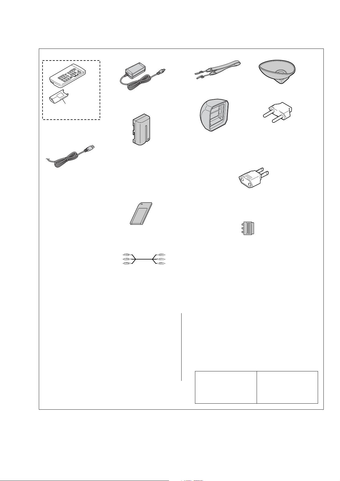
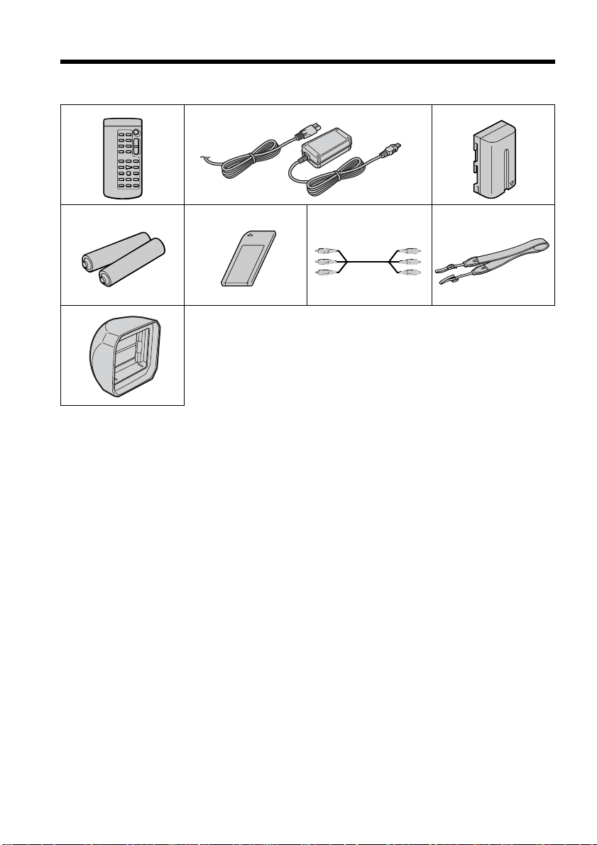
Checking supplied accessories.
Make sure that the following accessories are supplied with your camcorder.
DCR-VX2100/VX2100E
AC Adaptor (1)
0
1-477-533-51
Battery case
(3-053-056-01)
Wireless Remote Commander (1)
(RMT-811)
1-475-950-53
Rechargeable battery pack (1)
(NP-F330)
A-7094-140-A
(US,CND model)
A-7094-141-A
Power cord (Main lead) (1)
(AUS model)
0
1-696-819-21
(AEP, UK, E, HK, AUS, JE model)
A-7095-596-A
(CH model)
Power cord (Main lead) (1)
(AEP, E model)
0
1-769-608-11
Power cord (Main lead) (1)
(KR model)
0
1-776-985-11
Power cord (Main lead) (1)
(CH model)
0
1-782-476-13
Power cord (Main lead) (1)
Memory stick (1)
(MSA-8A)
A-7024-735-A
(UK, HK model)
0
1-783-374-11
Power cord (Main lead) (1)
(US, CND model)
0
1-790-107-22
Power cord (Main lead) (1)
A/V connecting cable (1.5m) (1)
1-823-364-21
(JE model)
0
1-790-732-12
Other accessories
3-087-414-11 MANUAL, INSTRUCTION (ENGLISH)
3-087-414-21 MANUAL, INSTRUCTION (FRENCH) (CND)
3-087-414-31 MANUAL, INSTRUCTION (SPANISH/PORTUGUESE)
3-087-414-41 MANUAL, INSTRUCTION (TRADITIONAL CHINESE)
3-087-414-51 MANUAL, INSTRUCTION (ARABIC) (VX2100:E)
(VX2100:US,CND,E,HK,JE)
(VX2100:E,HK)
(VX2100:E,JE)
Shoulder strap (1)
3-987-015-01
Eye cup (1)
3-087-515-01
2-pin conversion adaptor (1)
Hood with a lens cap (1)
3-088-528-01
(JE model)
1-569-007-12
2-pin conversion adaptor (1)
(E, HK model)
1-569-008-12
21-pin adaptor (1)
(AEP, UK model)
1-770-783-21
• Abbreviation
CND : Canadian model
AUS : Australian model
CH : Chinese model
HK : Hong Kong model
KR : Korea model
JE : Tourist model
3-087-415-31 MANUAL, INSTRUCTION (FRENCH/GERMAN)
3-087-415-41 MANUAL, INSTRUCTION (DUTCH/ITALIAN) (AEP)
3-087-415-51 MANUAL, INSTRUCTION (ARABIC/PERSIAN)
3-087-415-61 MANUAL, INSTRUCTION (TRADITIONAL CHINESE)
3-087-415-71 MANUAL, INSTRUCTION (SIMPLIFIED CHINESE)
(VX2100E:AEP,E,JE)
(VX2100E:E)
(VX2100E:HK)
3-087-414-61 MANUAL, INSTRUCTION (KOREAN) (VX2100:JE,KR)
3-087-415-11 MANUAL, INSTRUCTION (ENGLISH/RUSSIAN) (VX2100E)
3-087-415-21 MANUAL, INSTRUCTION (SPANISH/PORTUGUESE) (AEP)
— 3 —
Note :
The components identified by
mark 0 or dotted line with mark
0 are critical for safety.
Replace only with part number
specified.
Note :
Les composants identifiés par
une marque 0 sont critiques
pour la sécurité.
Ne les remplacer que par une
pièce portant le numéro spécifié.

DCR-VX2100/VX2100E
SAFETY CHECK-OUT
After correcting the original service problem, perform the following
safety checks before releasing the set to the customer.
1. Check the area of your repair for unsoldered or poorly-soldered
connections. Check the entire board surface for solder splashes
and bridges.
2. Check the interboard wiring to ensure that no wires are
"pinched" or contact high-wattage resistors.
3. Look for unauthorized replacement parts, particularly
transistors, that were installed during a previous repair . Point
them out to the customer and recommend their replacement.
4. Look for parts which, through functioning, show obvious signs
of deterioration. Point them out to the customer and
recommend their replacement.
5. Check the B+ voltage to see it is at the values specified.
6. Flexible Circuit Board Repairing
• Keep the temperature of the soldering iron around 270˚C
during repairing.
• Do not touch the soldering iron on the same conductor of the
circuit board (within 3 times).
• Be careful not to apply force on the conductor when soldering
or unsoldering.
— 4 —
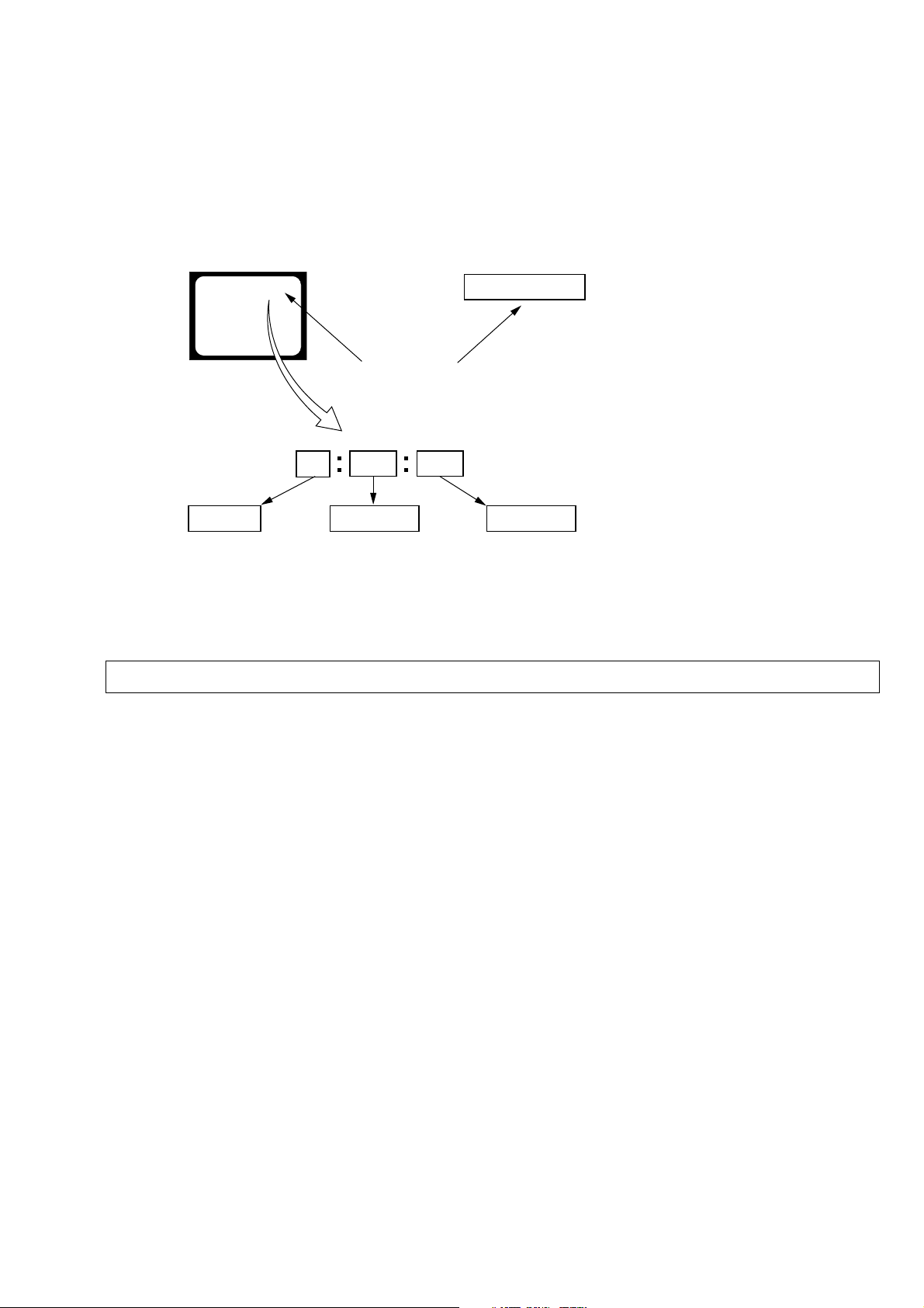
SELF-DIAGNOSIS FUNCTION
DCR-VX2100/VX2100E
1. SELF-DIAGNOSIS FUNCTION
When problems occur while the unit is operating, the self-diagnosis
function starts working, and displays on the viewf inder, LCD screen
or LCD window what to do. This function consists of two display;
self-diagnosis display and service mode display.
Details of the self-diagnosis functions are provided in the Instruction
manual.
Viewfinder or LCD screen LCD window
C : 3 1 : 1 1
Blinks at 3.2Hz
1 1
Repaired by:
C : Corrected by customer
H : Corrected by dealer
E : Corrected by service
engineer
C
Indicates the appropriate
step to be taken.
E.g.
31 ....Reload the tape.
32 ....Turn on power again.
3 1
Block
2. SELF-DIAGNOSIS DISPLAY
When problems occur while the unit is operating, the counter of the
viewfinder, LCD screen or LCD window consists of an alphabet
and 4-digit numbers, which blinks at 3.2 Hz. This 5-character display
indicates the “repaired by:”, “block” in which the problem occurred,
and “detailed code” of the problem.
C : 3 1 : 11
Detailed Code
Refer to
"Self-diagnosis Code Table".
Note: The “self-diagnosis display” data will be backed up by the coin-type lithium battery of ZM-030 board BT801, 802. When the (upper) handle block
is removed, the “self-diagnosis display” data will be lost by initialization.
— 5 —

DCR-VX2100/VX2100E
3. SELF-DIAGNOSIS CODE TABLE
Self-diagnosis Code
Block
Function
Repaired by:
C
04
C
21
C
22
C
31
C
31
C
31
C
31
C
31
C
31
C
31
C
31
C
31
C
31
C
32
C
32
C
32
C
32
C
32
C
32
C
32
C
32
C
32
C
32
Note: Add the sentence as follows.
If other codes are displayed, service is required.
Please send the set to a specialized center.
Detailed
Code
00
00
00
10
11
20
21
22
23
24
30
40
42
10
11
20
21
22
23
24
30
40
42
Non-standard battery is used.
Condensation.
Video head is dirty.
LOAD direction. Loading does not
complete within specified time
UNLOAD direction. Loading does not
complete within specified time
T reel side tape slacking when unloading
Winding S reel fault when counting the
rest of tape.
T reel fault.
S reel fault.
T reel fault.
FG fault when starting capstan.
FG fault when starting drum.
FG fault during normal drum operations.
LOAD direction loading motor time-
out.
UNLOAD direction loading motor
time-out.
T reel side tape slacking when
unloading.
Winding S reel fault when counting the
rest of tape.
T reel fault.
S reel fault.
T reel fault.
FG fault when starting capstan.
FG fault when starting drum
FG fault during normal drum
operations
Symptom/State
Correction
Use the info LITHIUM battery.
Remove the cassette, and insert it again after one hour.
Clean with the optional cleaning cassette.
Load the tape again, and perform operations from the beginning.
Load the tape again, and perform operations from the beginning.
.
Load the tape again, and perform operations from the beginning.
Load the tape again, and perform operations from the beginning.
Load the tape again, and perform operations from the beginning.
Load the tape again, and perform operations from the beginning.
Load the tape again, and perform operations from the beginning.
Load the tape again, and perform operations from the beginning.
Load the tape again, and perform operations from the beginning.
Load the tape again, and perform operations from the beginning.
Remove the battery or power cable, connect, and perform
operations from the beginning.
Remove the battery or power cable, connect, and perform
operations from the beginning.
Remove the battery or power cable, connect, and perform
operations from the beginning.
Remove the battery or power cable, connect, and perform
operations from the beginning.
Remove the battery or power cable, connect, and perform
operations from the beginning.
Remove the battery or power cable, connect, and perform
operations from the beginning.
Remove the battery or power cable, connect, and perform
operations from the beginning.
Remove the battery or power cable, connect, and perform
operations from the beginning.
Remove the battery or power cable, connect, and perform
operations from the beginning.
Remove the battery or power cable, connect, and perform
operations from the beginning.
— 6 —
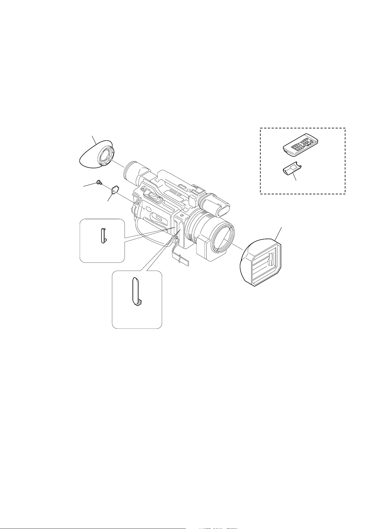
MAIN PARTS
Note:
• Follow the disassembly procedure in the numerical order given.
• Items marked “*” are not stocked since they are seldom required for routine service.
Some delay should be anticipated when ordering these items.
• The parts numbers of such as a cabinet are also appeared in this section.
Refer to the parts number mentioned below the name of parts to order.
1. ORNAMENTAL PARTS
Eye cup
3-087-515-01
DCR-VX2100/VX2100E
Screw (M2),
lock ace, P2
3-080-203-41
CPC cover
3-060-677-11
Jack cover (L)
3-060-541-21
Jack cover (AV)
3-060-540-21
Battery case lid
3-053-056-11
Remote commander (RMT-811)
1-475-950-53
Hood with a lens cap
3-088-528-01
— 7 —

DCR-VX2100/VX2100E
9-876-288-41
Sony EMCS Co.
— 8 —
2003J1600-1
©2003.10
Published by DI CS Strategy Div.
3-087-414-11 (1)
Digital
Video Camera
Recorder
Operating Instructions
Before operating the unit, please read this manual thoroughly,
and retain it for future reference.
Owner’s Record
The model and serial numbers are located on the bottom. Record the
serial number in the space provided below. Refer to these numbers
whenever you call upon your Sony dealer regarding this product.
Model No. DCR-VX2100 Model No. AC-
Serial No. Serial No.
DCR-VX2100
©2003 Sony Corporation
Congratulations on your purchase of this Sony Digital Handycam camcorder. With your Digital
Welcome!
Handycam, you can capture life’s precious moments with superior picture and sound quality. Your Digital
Handycam is loaded with advanced features, but at the same time it is very easy to use. You will soon be
producing home video that you can enjoy for years to come.
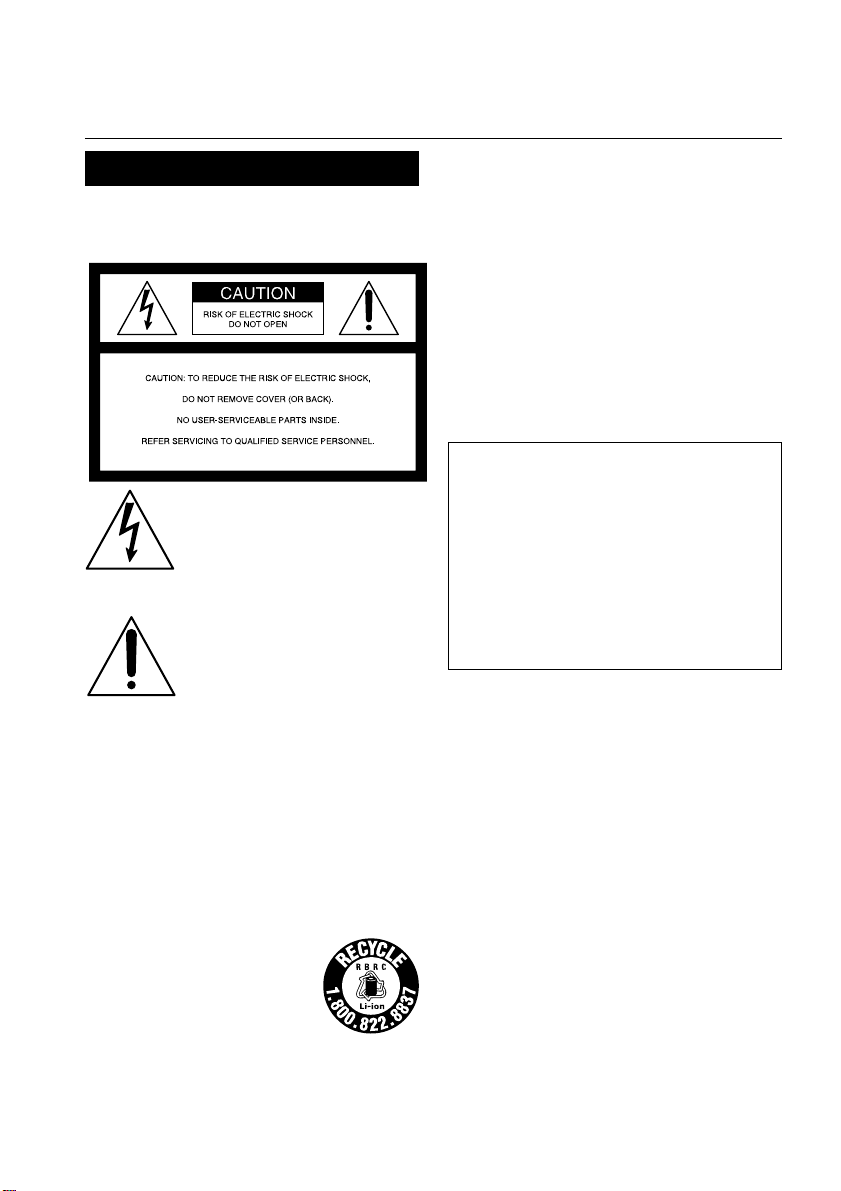
WARNING
To prevent fire or shock hazard, do
not expose the unit to rain or
moisture.
This symbol is intended to alert
the user to the presence of
uninsulated “dangerous voltage”
within the product’s enclosure
that may be of sufficient
magnitude to constitute a risk of
electric shock to persons.
This symbol is intended to alert
the user to the presence of
important operating and
maintenance (servicing)
instructions in the literature
accompanying the appliance.
Notice
If static electricity or electromagnetism causes
data transfer to discontinue midway (fail),
restart the application or disconnect and
connect the i.LINK cable again.
For customers in the U.S.A. and
CANADA
CAUTION
TO PREVENT ELECTRIC SHOCK, MATCH WIDE
BLADE OF PLUG TO WIDE SLOT, FULLY INSERT.
RECYCLING LITHIUM-ION BATTERIES
Lithium-Ion batteries are
recyclable.
You can help preserve our
environment by returning
your used rechargeable
batteries to the collection and
recycling location nearest you.
For more information regarding recycling of
rechargeable batteries, call toll free 1-800-8228837, or visit http://www.rbrc.org/
Caution: Do not handle damaged or leaking
2
Lithium-Ion batteries.
“Memory Stick”
This device complies with Part 15 of the FCC Rules.
Operation is subject to the following two conditions:
(1) This device may not cause harmful interference, and
(2) this device must accept any interference received,
including interference that may cause undesired operation.
This Class B digital apparatus complies with Canadian
ICES-003.
For the customers in the U.S.A.
If you have any questions about this product, you
may call:
Sony Customer Information Center 1-800-222SONY (7669)
The number below is for the FCC related matters
only.
Regulatory Information
Declaration of Conformity
Trade Name: SONY
Model No.: DCR-VX2100
Responsible Party: Sony Electronics Inc.
Address: 680 Kinderkamack
Telephone No.: 201-930-6972
This device complies with Part 15 of the FCC Rules.
Operation is subject to the following two
conditions: (1) This device may not cause harmful
interference, and (2) this device must accept any
interference received, including interference that
may cause undesired operation.
Road, Oradell,
NJ07649 U.S.A
CAUTION
You are cautioned that any changes or modifications
not expressly approved in this manual could void your
authority to operate this equipment.
Note:
This equipment has been tested and found to comply
with the limits for a Class B digital device, pursuant to
Part 15 of the FCC Rules. These limits are designed to
provide reasonable protection against harmful
interference in a residential installation. This
equipment generates, uses, and can radiate radio
frequency energy and, if not installed and used in
accordance with the instructions, may cause harmful
interference to radio communications. However, there
is no guarantee that interference will not occur in a
particular installation. If this equipment does cause
harmful interference to radio or television reception,
which can be determined by turning the equipment off
and on, the user is encouraged to try to correct the
interference by one or more of the following measures:
—Reorient or relocate the receiving antenna.
— Increase the separation between the equipment and
receiver.
Connect the equipment into an outlet on a circuit
—
different from that to which the receiver is connected.
—Consult the dealer or an experienced radio/TV
technician for help.
The supplied interface cable must be used with the
equipment in order to comply with the limits for a digital
device pursuant to subpart B of Part 15 of FCC Rules.

Table of contents
Quick Start Guide ............................................... 4
Getting Started
Using this manual ............................................... 6
Checking supplied accessories ......................... 8
Step 1 Preparing the power supply ................ 9
Step 2 Setting the date and time .................... 14
Step 3 Inserting a cassette ............................... 15
Recording – Basics
Recording a picture .......................................... 16
Shooting backlit subjects
(BACK LIGHT) ................................ 23
Using the spot light function ............ 24
Self-timer recording ........................... 25
Checking the recording – END SEARCH /
EDITSEARCH / Rec Review ....................... 26
Playback – Basics
Playing back a tape ........................................... 27
Viewing the recording on TV ......................... 31
Advanced Recording Operations
Recording a still image on a tape
– Tape Photo recording ................................ 32
Shooting with all the pixels
– PROG. SCAN ............................................... 34
Using the guide frame ..................................... 35
Using the wide mode ....................................... 36
Using the fader function .................................. 38
Using special effects – Picture effect .............. 40
Using special effects – Digital effect .............. 41
Shooting with manual adjustment ................. 44
Adjusting the white balance ........................... 50
Adjusting recording level manually
– Sound recording level ................................ 52
Presetting the adjustment for picture quality
– Custom preset ............................................. 54
Using the PROGRAM AE function ................ 56
Focusing manually ........................................... 59
Interval recording ............................................. 60
Frame by frame recording – Cut recording .. 62
Marking an Index ............................................. 63
Advanced Playback Operations
Quickly locating a scene using the zero set
memory function ........................................... 64
Searching for a recording by index
– Index search ................................................. 65
Searching the boundaries of recorded tape by
title – Title search ........................................... 67
Searching a recording by date
– Date search ................................................... 68
Searching for a photo
– Photo search/Photo scan ........................... 70
Playing back a tape with picture effects ........ 72
Playing back a tape with digital effects ......... 73
Editing
Dubbing a tape .................................................. 74
Dubbing only desired scenes
– Digital program editing ............................. 76
Using with an analog video unit and a PC
– Signal convert function .............................. 88
Recording video or TV programs .................. 89
Inserting a scene from a VCR
– Insert editing ............................................... 93
Audio dubbing .................................................. 95
Superimposing a title ....................................... 99
Making your own titles.................................. 103
Labeling a cassette .......................................... 105
Erasing the cassette memory data ................ 107
Customizing Your Camcorder
Changing the menu settings ......................... 109
“Memory Stick” Operations
Using a “Memory Stick” – introduction ...... 116
Recording still images on a “Memory Stick”
– Memory Photo recording ........................ 121
Superimposing a still image in a “Memory
Stick” on a moving picture
– MEMORY MIX .......................................... 125
Recording an image from a tape as a still
image ............................................................. 128
Copying still images from a tape
– Photo save .................................................. 131
Viewing a still picture
– Memory Photo playback .......................... 133
Copying an image recorded on a “Memory
Stick” to tapes ............................................... 136
Playing back images continuously
– SLIDE SHOW ............................................ 138
Preventing accidental erasure
– Image protection ....................................... 139
Deleting images .............................................. 140
Writing a print mark – Print mark ............... 143
Additional Information
Usable cassettes ............................................... 144
About i.LINK ................................................... 146
Troubleshooting .............................................. 148
Self-diagnosis display .................................... 154
Warning indicators and messages ............... 155
Using your camcorder abroad ...................... 157
Maintenance information and
precautions ................................................... 158
Specifications ................................................... 163
Quick Reference
Identifying the parts and controls ................ 164
Quick Function Guide .................................... 173
Index ................................................................. 174
3
Quick Start Guide
PUSH
This guide introduces you to the basic way of recording/
playback. See the pages in parentheses “( )” for more
information.
Connecting the power cord (p. 13)
Use the battery pack when using your camcorder outdoors (p. 9).
Connect the plug with its
v mark facing toward the
LCD panel side.
AC Adaptor
Quick Start Guide
(supplied)
Inserting a cassette (p. 15)
1 While pressing the
small blue button on
the EJECT switch,
slide it in the direction
of the arrow.
2
Push the middle
portion of the back of
the cassette to insert it.
Insert the cassette into
the cassette
compartment with the
window facing out
and the write-protect
tab facing upward.
Window
Open the DC IN jack
cover.
3 Close the cassette
compartment by
pressing the PUSH
mark on it.
4 Close the cassette lid
by pressing the
PUSH button on the
cassette lid.
4
Write-protect tab
Recording a picture (p. 16)
Viewfinder
When the LCD panel
is closed, use the
viewfinder placing
your eye against its
eyecup.
4 Press START/
STOP. Your
camcorder
starts
recording. To
stop recording,
press START/
STOP again.
POWER
VCR
(CHG)
OFF
CAMERA
MEMORY
3 Slide OPEN
back in the
B mark
direction to
open the
LCD panel.
Monitoring the playback picture on the LCD
screen (p. 27)
OPEN
1 Open the shutter of the
hood with a lens cap. For
more information about
attaching the hood with a
lens cap, see page 167.
2 Set the POWER switch to
CAMERA while pressing the
small green button.
If the ND1 or ND2 indicator
flashes, see page 47.
(CHG)
OFF
POWER
VCR
CAMERA
MEMORY
Quick Start Guide
1 Set the POWER
switch to VCR while
pressing the small
green button.
2 Press m to rewind the
tape.
3 Press N to start
playback.
VCR
(CHG)
OFF
CAMERA
POWER
MEMORY
NOTE
Do not pick up your camcorder by holding
the viewfinder, the LCD panel, the battery
pack, or the microphone.
REW
PLAY
5

— Getting Started —
Using this manual
As you read through this manual, buttons and settings on your camcorder are shown in
capital letters.
e.g. Set the POWER switch to CAMERA.
When you carry out an operation, you can hear a beep or a melody sound to indicate
that the operation is being carried out.
Note on cassette memory
Your camcorder is based on the DV format. You can only use mini DV cassettes with
your camcorder. We recommend that you use a tape with cassette memory .
The functions which require different operations depending on whether or not the tape
has cassette memory are:
•Searching the end point of the recording – end search (p. 26,30)
•Searching a recording by index – index search (p. 65)
•Searching a recording by date – date search (p. 68)
•Searching for a photo – photo search (p. 70).
The functions you can operate only with cassette memory are:
•Searching the boundaries of recorded tape by title – title search (p. 67)
•Superimposing a title (p. 99)
•Making your own titles (p. 103)
•Labeling a cassette (p. 105).
For details, see page 144.
You see this mark in the introduction of the features that are operated only with
cassette memory.
Tapes with cassette memory are marked with (Cassette Memory).
6
Using this manual
Note on TV color systems
TV color systems differ by country or region. To view your recordings on a TV, you
need an NTSC system-based TV.
Copyright precautions
Television programs, films, video tapes, and other materials may be copyrighted.
Unauthorized recording of such materials may be contrary to the provision of the
copyright laws.
Precautions on camcorder care
Lens and LCD screen/finder
•The LCD screen and the finder are manufactured using extremely high-precision
technology, so over 99.99% of the pixels are operational for effective use.
However, there may be some tiny black points and/or bright points (white, red,
blue or green in color) that constantly appear on the LCD screen and the finder.
These points are normal in the manufacturing process and do not affect the
recording in any way.
•Do not directly shoot the sun. Doing so might cause your camcorder to malfunction.
Take pictures of the sun in low light conditions such as dusk.
•Do not let your camcorder get wet. Keep your camcorder away from rain and sea
water. Letting your camcorder get wet may cause your camcorder to malfunction.
Sometimes this malfunction cannot be repaired [a].
•Never leave your camcorder exposed to temperatures above 60 °C (140 °F), such as in
a car parked in the sun or under direct sunlight [b].
•Be careful when placing the camera near a window or outdoors. Exposing the LCD
screen, the finder or the lens to direct sunlight for long periods may cause
malfunctions [c].
Getting Started
[a] [b][c]
Contents of the recording cannot be compensated if recording or playback is not made due to a
malfunction of the camcorder, video tape, etc.
7
Checking supplied accessories
Make sure that the following accessories are supplied with your camcorder.
12 3
4
8
1 Wireless Remote Commander (1)
(p. 170)
2 AC-L15A/L15B AC Adaptor (1), Power
cord (1) (p. 10)
3 NP-F330 rechargeable battery pack (1)
(p. 9, 10)
4 Size AA (R6) battery for Remote
Commander (2) (p. 171)
57
6
5 “Memory Stick” (1) (p. 116)
6 A/V connecting cable (1) (p. 31, 74)
7 Shoulder strap (1) (p. 168)
8 Hood with a lens cap (1) (p. 167)
8
Step 1 Preparing the power supply
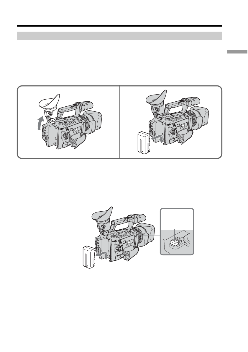
Installing the battery pack
Install the battery pack to use your camcorder outdoors.
(1) Lift up the viewfinder.
(2) Insert the battery pack in the direction of the V mark on the battery pack. Slide
the battery pack until it clicks.
12
To remove the battery pack
Lift up the viewfinder.
Slide the battery pack out in the direction of the arrow while pressing BATT RELEASE
down.
Getting Started
BATT
RELEASE
9
Step 1 Preparing the power supply
Charging the battery pack
Use the battery pack after charging it.
Your camcorder operates only with the “InfoLITHIUM” battery pack (L series).
(1) Open the DC IN jack cover and connect the AC Adaptor supplied with your
camcorder to the DC IN jack with the plug’s v mark facing toward the LCD
panel side.
(2) Connect the power cord to the AC Adaptor.
(3) Connect the power cord to a wall outlet.
(4) Set the POWER switch to OFF (CHG). Charging begins.
The remaining battery time is indicated in minutes on the display window.
When the remaining battery indicator changes to u, normal charge is completed. To
fully charge the battery (full charge), leave the battery pack attached for about one hour
after normal charge is completed until FULL appears on the display window. Fully
charging the battery allows you to use the battery longer than usual.
1
4
(CHG)
OFF
POWER
VCR
CAMERA
MEMORY
10
After charging the battery pack
Disconnect the AC Adaptor from the DC IN jack on your camcorder.
Note on the remaining battery time indicator
The remaining battery time indicator on the LCD screen/display window or in the
viewfinder indicates the recording time using the viewfinder. The indicator may not be
correct, depending on the conditions in which you are recording. When you close the
LCD panel and open it again, it takes about one minute for the correct remaining
battery time to be displayed.
Notes
•
Prevent metallic objects from coming into contact with the metal parts of the DC plug of
the AC Adaptor. This may cause a short-circuit, damaging the AC Adaptor.
•Keep the battery pack dry.
•
When the battery pack is not to be used for a long time, charge the battery pack once
fully, and then use it until it fully discharges again. Keep the battery pack in a cool place.

Step 1 Preparing the power supply
Until your camcorder calculates the actual remaining battery time
“- - - - min” appears in the display window.
While charging the battery pack, no indicator appears or the indicator flashes in
the display window in the following cases:
– The battery pack is not installed correctly.
– The AC Adaptor is disconnected.
– Something is wrong with the battery pack.
When using the AC Adaptor
Be sure to use it near the wall outlet. If a malfunction occurs, disconnect the plug from
the wall outlet.
Charging time
Battery pack Full charge (Normal charge)
NP-F330 (supplied) 150 (90)
NP-F550 210 (150)
NP-F730/F750 300 (240)
NP-F960 420 (360)
Approximate minutes to charge an empty battery pack
Recording time
Recording with Recording with
Battery pack the viewfinder the LCD screen
Continuous Typical* Continuous Typical*
NP-F330 (supplied) 75 (65) 40 (35) 60 (55) 30 (30)
NP-F550 150 (135) 80 (75) 130 (115) 70 (60)
NP-F730 265 (240) 145 (130) 230 (205) 125 (110)
NP-F750 315 (275) 175 (150) 265 (235) 145 (130)
NP-F960 575 (515) 320 (285) 480 (430) 265 (240)
Getting Started
Approximate minutes of recording time when you use a fully charged battery
Numbers in parentheses “( )” indicate the time using a normally charged battery.
You cannot use the NP-500/510/710 battery pack on your camcorder.
* Approximate minutes when recording while you repeat recording start/stop,
zooming and turning the power on/off. The actual battery life may be shorter.
11

Step 1 Preparing the power supply
Playing time
Battery pack Playing time Playing time
NP-F330 (supplied) 90 (80) 110 (95)
NP-F550 185 (165) 225 (195)
NP-F730 305 (275) 385 (345)
NP-F750 375 (335) 460 (415)
NP-F960 680 (610) 830 (745)
Approximate minutes of playing time when you use a fully charged battery
Numbers in parentheses “( )” indicate the time using a normally charged battery.
You cannot use the NP-500/510/710 battery pack on your camcorder.
Notes
•The supplied battery pack is charged a little.
•Some types of the battery packs may not be sold in your region or country.
•Approximate recording time and continuous playing time at 25°C (77°F). The battery
life will be shorter if you use your camcorder in a cold environment.
What is ”InfoLITHIUM?”
The “InfoLITHIUM” is a lithium ion battery pack which can exchange data such as
battery consumption with compatible video equipment. This unit is compatible with the
“InfoLITHIUM” battery pack (L series). Your camcorder operates only with the
“InfoLITHIUM” battery. “InfoLITHIUM” battery packs (L series) have the
mark.
“InfoLITHIUM” is a trademark of Sony Corporation.
on LCD screen with LCD closed
12
If the camcorder is immediately turned off
Even if the remaining battery time is enough to operate, charge the battery pack fully
again. The correct remaining time is displayed.
Step 1 Preparing the power supply
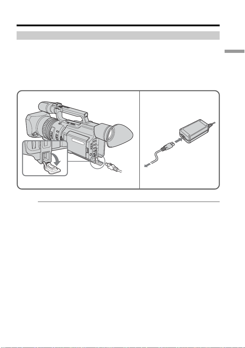
Connecting to a wall outlet
When you use your camcorder for a long time, we recommend that you power it from a
wall outlet using the AC Adaptor.
(1) Open the DC IN jack cover and connect the AC Adaptor to the DC IN jack on
your camcorder with the plug’s v mark facing toward the LCD panel side.
(2) Connect the power cord to the AC Adaptor.
(3) Connect the power cord to a wall outlet.
Getting Started
12
Precaution
The set is not disconnected from the AC power source (house current) as long as it is
connected to the wall outlet, even if the set itself has been turned off.
Notes
•The power cord must only be changed at an authorized service shop.
•AC Adaptor can supply power even if the battery pack is attached to your camcorder.
•The DC IN jack has source priority. This means that the battery pack cannot supply
any power if the power cord is connected to the DC IN jack, even when the power
cord is not plugged into a wall outlet.
Using a car battery
Use the Sony DC Adaptor/Charger (optional).
13
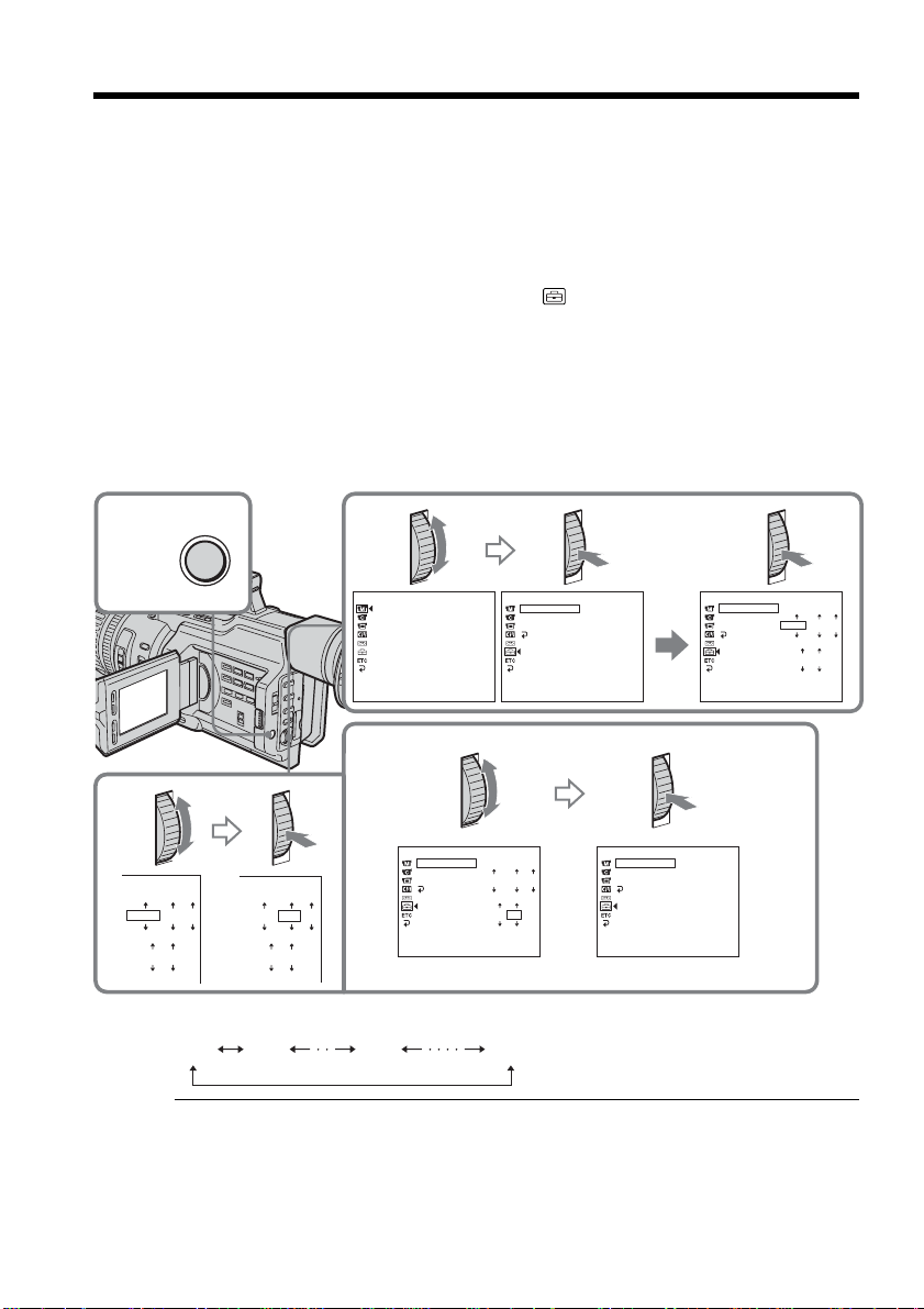
Step 2 Setting the date and time
Set the date and time when you use your camcorder for the first time. "CLOCK SET"
will be displayed each time that you set the POWER switch to CAMERA or MEMORY
unless you set the date and time settings.
If you do not use your camcorder for about four months, the date and time may be
cleared from memory (bars may appear) because the built-in rechargeable battery
installed in your camcorder will have been discharged (p.160).
First, set the year, then the month, the day, the hour and then the minute.
(1) Press MENU to display the menu in the standby mode.
(2) Turn the SEL/PUSH EXEC dial to select
(3) Turn the SEL/PUSH EXEC dial to select CLOCK SET, then press the dial.
Turn the SEL/PUSH EXEC dial to adjust to the desired year, then press the dial.
(4)
(5) Set the month, day and hour by turning the SEL/PUSH EXEC dial and
pressing the dial.
(6) Set the minute by turning the SEL/PUSH EXEC dial and pressing the dial by
the time signal. The clock starts to move.
(7) Press MENU to erase the menu display.
, then press the dial.
1,7
4
2003
12 00
MENU
2
MANUAL SET
AUTO SHTR
PROG. SCAN
[MENU] : END [MENU] : END [MENU] : END
SETUP MENU
CLOCK SET
LTR SIZE
DEMO MODE
RETURN
JAN
12:00:00
1 2003
AM
3
SETUP MENU
CLOCK SET
LTR SIZE
DEMO MODE
RETURN
2003
12 00
6
SETUP MENU
CLOCK SET
LTR SIZE
2003
JUL
JAN
DEMO MODE
RETURN
1
2003
JAN
1
AM
12 00
AM
[MENU] : END [MENU] : END
5 30
4
PM
The year changes as follows:
1995 1996 20792003
If you do not set the date and time
“– –:– –:– –” (time) and “--- -- ----” (date) are recorded on the data code of the tape and
the “Memory Stick.”
SETUP MENU
CLOCK SET
LTR SIZE
DEMO MODE
RETURN
JUL
5:30:00
4 2003
PM
JAN
1
AM
14
Note on the time indicator
The internal clock of your camcorder operates on a 12-hour cycle.
•12:00 AM stands for midnight.
•12:00 PM stands for noon.
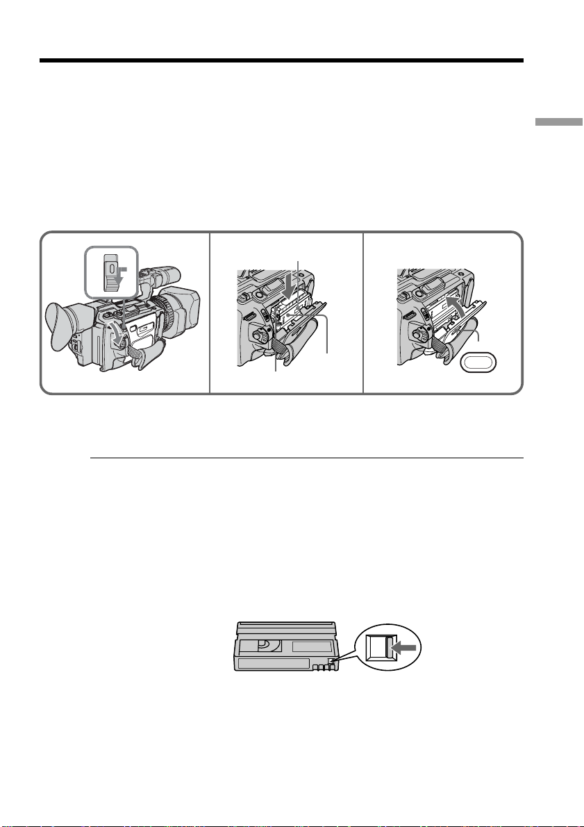
Step 3 Inserting a cassette
(1) Install the power source.
(2) While pressing the small blue button on the EJECT switch, slide it in the
direction of the arrow. After the cassette lid is opened, the cassette
compartment automatically opens.
(3) Push the middle portion of the back of the cassette to insert it.
Insert the cassette in a straight line deeply into the cassette compartment with
the window facing out and the write-protect tab facing upward.
(4) Close the cassette compartment by pressing the PUSH mark on it.
(5) Close the cassette lid until it clicks by pressing the PUSH button on the lid.
Getting Started
2
3,4 5
Window
PUSH
Write-protect tab
To eject a cassette
Follow the procedure above, and take out the cassette in step 3.
Note
The cassette lid will not be closed when you press any part of the lid other than the
PUSH button.
When you use mini DV cassettes with cassette memory
Read the instruction about cassette memory to use this function properly (p. 144).
To prevent accidental erasure
Slide the write-protect tab on the cassette to SAVE.
PUSH
If the grip strap prevents the cassette lid from opening fully
Adjust the length of the grip strap (p. 168).
If Q flashes even if the cassette has been inserted
Press the PUSH button again to close the cover firmly.
15

— Recording – Basics —
Recording a picture
Your camcorder automatically focuses for you.
(1) Open the shutter of the hood with a lens cap. For more information about
attaching the hood with a lens cap, see page 167.
(2) Install the power source and insert a cassette. See “Step 1” to “Step 3” (p. 9 to
15) for more information.
(3) Set the POWER switch to CAMERA while pressing the small green button.
Your camcorder is set to the standby mode.
(4) Slide OPEN in the direction of the B mark to open the LCD panel.
The picture now being shot is displayed on the LCD screen, and it disappears
from the viewfinder screen.
(5) Press START/STOP. Your camcorder starts recording. The “REC” indicator
appears. The camera recording lamps located on the front and rear of your
camcorder light up. To stop recording, press START/STOP again.
You can use REC START/STOP located on the handle or front instead of
START/STOP on the rear.
Camera recording lamps Microphone
1
4
OPEN
3
REC START/STOP
Handle REC START/STOP
2
POWER
VCR
5
(CHG)
OFF
CAMERA
MEMORY
If the ND1 or ND2 indicator flashes on the LCD screen or in the viewfinder
The ND filter is necessary. Set the ND FILTER selector to 1 or 2. However, if you change
the position during recording, the brightness of the picture may change or audio noise
may occur. This is not a malfunction. We recommend that you check the position of the
ND FILTER selector before shooting. See “Using the ND filter” on page 47.
Notes
•Fasten the grip strap firmly.
•Do not touch the microphone during recording.
40min
REC
0:00:01
3
VCR
(CHG)
OFF
CAMERA
LOCK
POW
ER
MEMORY
16

Recording a picture
Note on the recording mode
Your camcorder records and plays back in SP (standard play) mode and in LP (long
play) mode. Select SP or LP in the menu settings. In LP mode, you can record 1.5 times
as long as in SP mode.
When you record a tape on your camcorder in LP mode, we recommend playing the
tape on your camcorder.
Note on the LOCK switch
When you slide the LOCK switch to the left, the POWER switch can no longer be set to
MEMORY accidentally. The LOCK switch is set to the right as a default setting. We
recommend that you set the LOCK switch to the left when you record on a cassette.
Note on the progressive recording mode
If you intend to use the images on your PC or play the images back as still images, we
recommend that you set PROG. SCAN to ON in the menu settings before shooting (p.
34). The picture quality may improve in this mode, but if you shoot a moving subject,
the image may shake when it is played back.
To enable smooth transition
Transition between the last scene you recorded and the next scene is smooth as long as
you do not eject the cassette even if you turn off your camcorder. When you use a tape
with cassette memory, however, you can make the transition smooth even after ejecting
the cassette if you use the end search function (p. 26).
However, check the following:
•When you change the battery pack, set the POWER switch to OFF (CHG).
•Do not mix recordings in the SP mode and ones in the LP mode on one tape.
Note on tape transition
The playback picture may be distorted or the time code may not be written properly
between scenes when:
•You change the recording mode (SP/LP).
•You record in LP mode.
Recording – Basics
If you leave your camcorder in standby mode for five minutes while the cassette is
inserted
Your camcorder automatically turns off. This is to prevent tape wear and save battery
power. To resume the standby mode, set the POWER switch to OFF (CHG), and to
CAMERA again. When a cassette is not inserted, your camcorder does not turn off.
17
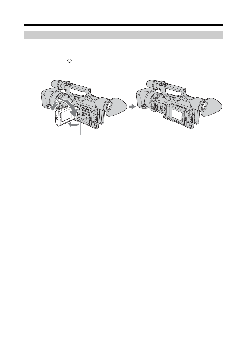
Recording a picture
180
Adjusting the LCD screen
The LCD panel is opened up to 90 degrees and it rotates about 90 degrees to the
viewfinder side and about 180 degrees to the lens side.
If you turn the LCD panel over so that it faces the other way in standby or recording
mode, the indicator appears on the LCD screen and in the viewfinder (Mirror
mode).
180
°
180°
90°
OPEN
To close the LCD panel, set it vertically and swing it into the camcorder body until it
clicks.
Note
When you open the LCD panel, the viewfinder is automatically turned off, however, it is
not turned off when the LCD panel is turned over or the camcorder is in mirror mode.
18
When you adjust the angle of the LCD panel
Make sure that the LCD panel is opened up to 90 degrees.
When using both the LCD screen and the viewfinder during shooting
The usable time of the battery pack when using both the LCD screen and the viewfinder
will be shorter a little than when using the viewfinder only.
Pictures in the mirror mode
The picture on the LCD screen is a mirror-image. However, the recording picture will
be normal.
During recording in mirror mode
ZERO SET MEMORY on the Remote Commander does not work.
Indicators in the mirror mode
The STBY indicator appears as zX and REC as z. Some of the other indicators appear
mirror-reversed and others are not displayed. However, if you close the LCD panel
with the LCD screen turned over, indicators appear normally.
Recording a picture
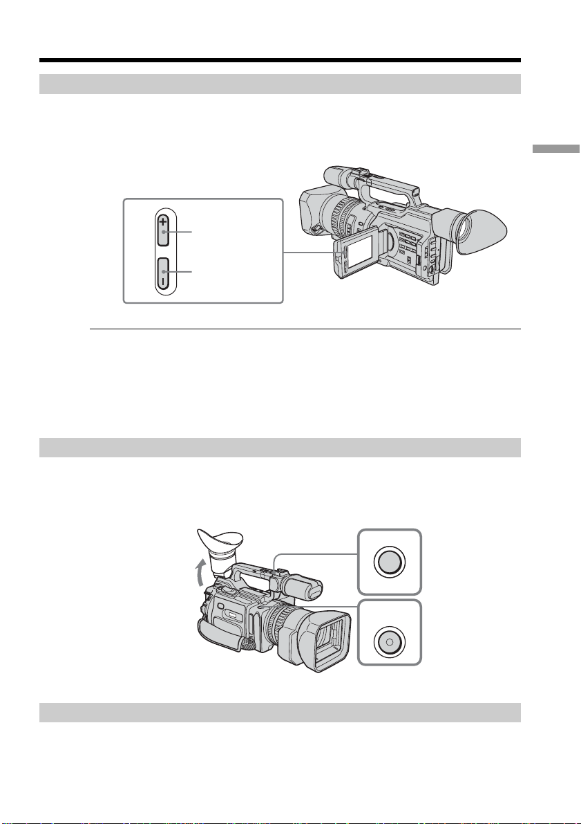
Adjusting the brightness of the LCD screen
To adjust the brightness of the LCD screen, press LCD BRIGHT + or –.
The battery life is longer when the LCD panel is closed. Use the viewfinder instead of
the LCD screen to save the battery power.
To brighten
Recording – Basics
LCD BRIGHT
To darken
On the LCD screen backlight
You can change the brightness of the backlight. Select LCD B.L. in the menu settings
(p. 109).
Even if you do the LCD screen adjustment using the LCD BRIGHT +/– buttons, or
using LCD B.L. and LCD COLOR items in the menu settings
The recorded picture will not be affected.
Recording in a low position
You can record in a low position to get an interesting recording angle. Lift up the
viewfinder or rotate the LCD panel with the screen facing up to record from a low
position. In this case, it is useful to use the REC START/STOP located on the handle or
front of the camcorder.
REC
T
S
REC
START/
STOP
P
O
T
S
/
T
R
A
After recording
(1) Set the POWER switch to OFF (CHG).
(2) Close the LCD panel.
(3) Eject the cassette.
(4) Remove the battery pack.
19
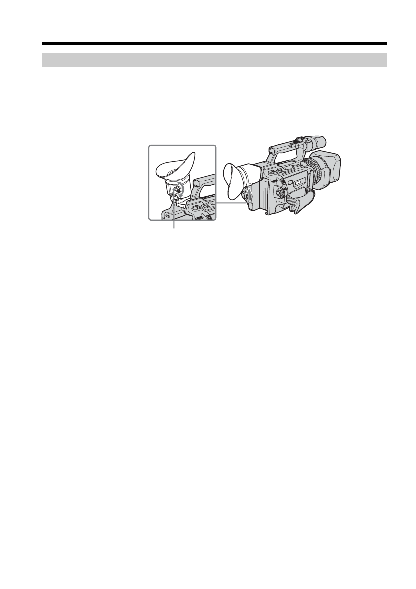
Recording a picture
Adjusting the viewfinder
If you record pictures with the LCD panel closed, check the picture with the viewfinder.
Adjust the viewfinder lens to your eyesight so that the images in the viewfinder come
into sharp focus.
Lift up the viewfinder and move the viewfinder adjustment lever.
Viewfinder adjustment lever
To adjust the brightness of the viewfinder screen, use the VF B.L. item in the menu
settings (p. 109).
Even if you adjust the viewfinder screen backlight
The recorded picture will not be affected.
The eyecup
You can attach the eyecup with the large part of it located on both left and right.
See page 167 for details.
20
Recording a picture
Using the zoom feature
To zoom using the zoom lever/handle zoom lever
Press the power zoom lever a little for a slower zoom. Press it deeper for a faster zoom.
Using the zoom function sparingly results in better-looking recordings.
“T” side: for telephoto (subject appears closer)
“W” side: for wide-angle (subject appears farther away)
When using the handle zoom lever, you can change the zooming speed using the
handle zoom switch.
H: Fast
L: Slow
Handle zoom switch
Recording – Basics
W
T
W
T
T
W
Notes
•When the handle zoom switch is set to OFF, you cannot operate the handle zoom
lever.
•The handle zoom switch does not interlock with the zoom lever of the camcorder.
When you shoot close to a subject
If you cannot get a sharp focus, press the “W” side of the power zoom lever until the
focus is sharp. You can shoot a subject that is at least about 80 cm (about 2 feet 5/8 inch)
away from the lens surface in the telephoto position, or about 1 cm (about 1/2 inch)
away in the wide-angle position.
To zoom using the zoom ring
Using the zoom ring, you can control the zoom by your desired speed and you can
make fine adjustments.
During recording, turn the zoom ring to the desired speed.
Zoom ring
For wide-angle
For telephoto
Note
If you turn the zoom ring quickly, the zoom may not respond to the zoom ring.
Rotate the zoom ring with appropriate speed.
21
Recording a picture
T
W
Using the disital zoom – Zoom greater than 12×
Zoom greater than 12× is performed digitally, if you set D ZOOM to 24× or 48× in the
menu settings. The digital zoom function is set to OFF as a default setting (p. 109). If
you use the digital zoom function, the picture quality deteriorates.
The right-ended portion of the bar shows the digital
zooming zone.
The digital zooming zone appears when you set
D ZOOM to 24× or 48×.
You cannot use the digital zoom:
– When you set PROG. SCAN to ON in the menu settings (p. 109).
– When the POWER switch is set to MEMORY.
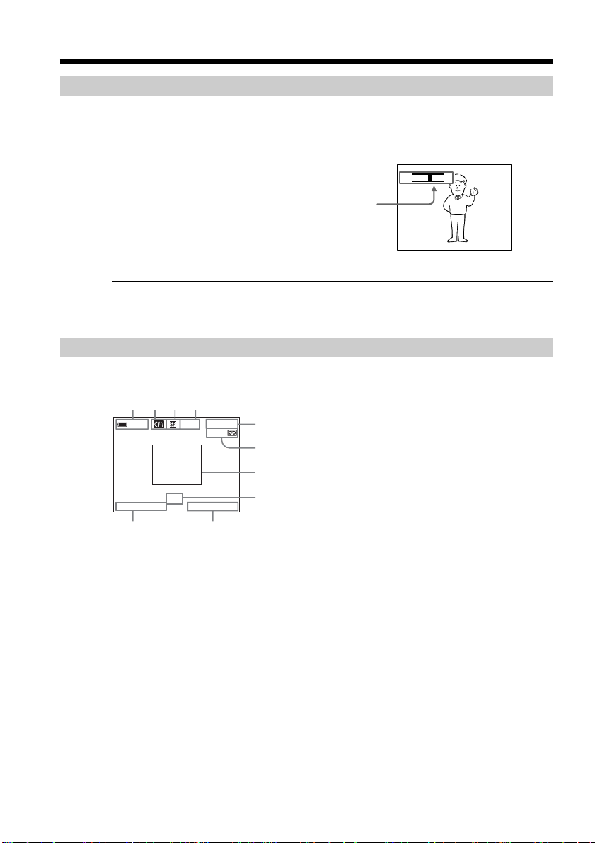
Indicators displayed during recording
The indicators are not recorded on the tapes.
[a] [b] [c] [d]
40
min
REC
0:00:01
45min
[e]
[f]
22
[g]
JUL 4 2003
ND
1
12:05:56PM
[h]
[j] [i]
[a]Remaining battery time
This appears after you turn on the power and wait for a while.
[b]Cassette memory
This appears when using a tape with cassette memory.
[c] Recording mode
[d]STBY/REC
[e]Time code/Tape counter
[f] Remaining tape
This appears after you insert a cassette.
[g]Guide frame
[h]ND filter
This flashes when the ND FILTER selector should be set. After you have set the ND
FILTER selector, the ND FILTER position selected is indicated. (When the ND OFF
position is selected, the indication disappears.)
[i] Time
The time is displayed about five seconds after the POWER switch is set to CAMERA
or MEMORY.
[j] Date
The date is displayed about five seconds after the POWER switch is set to CAMERA
or MEMORY.
 Loading...