

Page 1
DCR-TRV6/TRV6E/TRV11/
TRV11E/TRV20/TRV20E
RMT-808/809/811/812
Ver 1.1 2000. 06
SERVICE MANUAL
SERVICE MANUAL
Level 2
Photo : DCR-TRV20E
RMT-811
On the VC-240/241 board
This service manual provides the information that is premised the
circuit board replacement service and not intended repair inside the
VC-240/241 board.
Therefore, schematic diagram, printed wiring board and electrical parts
list of the VC-240/241 board are not shown.
The following pages are not shown.
Schematic diagram .......................... Pages 4-17 to 4-66
Printed wiring board......................... Pages 4-67 to 4-74
Electrical parts list............................ Pages 6-23 to 6-44
US Model
Canadian Model
Korea Model
DCR-TRV6/TRV11/TRV20
AEP Model
UK Model
Australian Model
Chinese Model
DCR-TRV6E/TRV11E/TRV20E
E Model
Hong Kong Model
Tourist Model
DCR-TRV6/TRV6E/TRV11/
TRV11E/TRV20/TRV20E
J MECHANISM
For MECHANISM ADJUSTMENTS, refer to the
“DV MECHANICAL ADJUSTMENT MANUAL
J MECHANISM ” (9-929-807-11).
DCR-TRV6/TRV11/TRV20 : NTSC model
DCR-TRV6E/TRV11E/TRV20E : PAL model
• Table showing differences is shown on page 4.
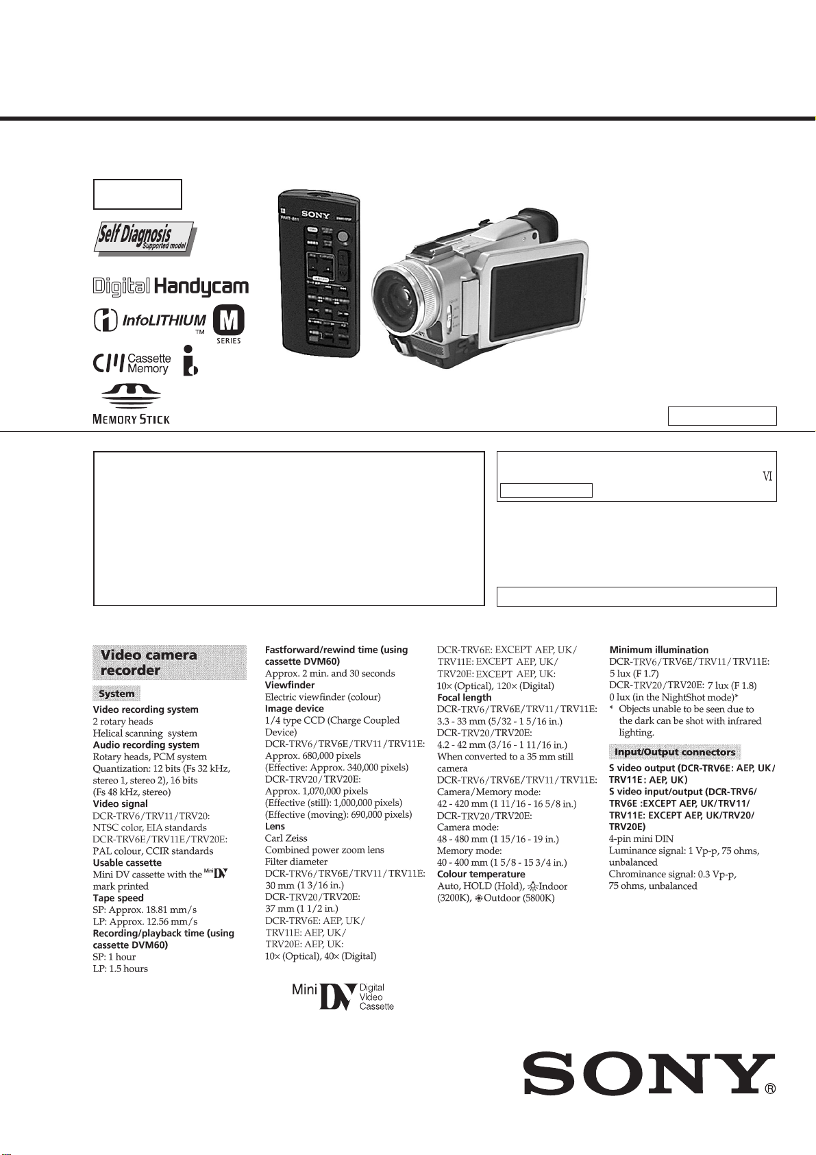
SPECIFICATIONS
— Continued on next page —
DIGITAL VIDEO CAMERA RECORDER
Page 2
SAFETY-RELATED COMPONENT WARNING!!
COMPONENTS IDENTIFIED BY MARK ! OR DO TTED LINE WITH
MARK ! ON THE SCHEMATIC DIAGRAMS AND IN THE PARTS
LIST ARE CRITICAL TO SAFE OPERATION. REPLACE THESE
COMPONENTS WITH SONY PARTS WHOSE PART NUMBERS
APPEAR AS SHOWN IN THIS MANUAL OR IN SUPPLEMENTS
PUBLISHED BY SONY.
SAFETY CHECK-OUT
After correcting the original service problem, perform the following
safety checks before releasing the set to the customer.
ATTENTION AU COMPOSANT AYANT RAPPORT
À LA SÉCURITÉ!
LES COMPOSANTS IDENTIFÉS P AR UNE MARQUE ! SUR LES
DIAGRAMMES SCHÉMA TIQUES ET LA LISTE DES PIÈCES SONT
CRITIQUES POUR LA SÉCURITÉ DE FONCTIONNEMENT. NE
REMPLACER CES COMPOSANTS QUE PAR DES PIÈSES SONY
DONT LES NUMÉROS SONT DONNÉS DANS CE MANUEL OU
DANS LES SUPPÉMENTS PUBLIÉS PAR SONY.
1. Check the area of your repair for unsoldered or poorly-soldered
connections. Check the entire board surface for solder splashes
and bridges.
2. Check the interboard wiring to ensure that no wires are
"pinched" or contact high-wattage resistors.
3. Look for unauthorized replacement parts, particularly
transistors, that were installed during a previous repair . Point
them out to the customer and recommend their replacement.
4. Look for parts which, through functioning, show obvious signs
of deterioration. Point them out to the customer and
recommend their replacement.
5. Check the B+ voltage to see it is at the values specified.
6. Flexible Circuit Board Repairing
• Keep the temperature of the soldering iron around 270˚C
during repairing.
• Do not touch the soldering iron on the same conductor of the
circuit board (within 3 times).
• Be careful not to apply force on the conductor when soldering
or unsoldering.
— 2 —
Page 3
• Table showing differences is shown on page 4.
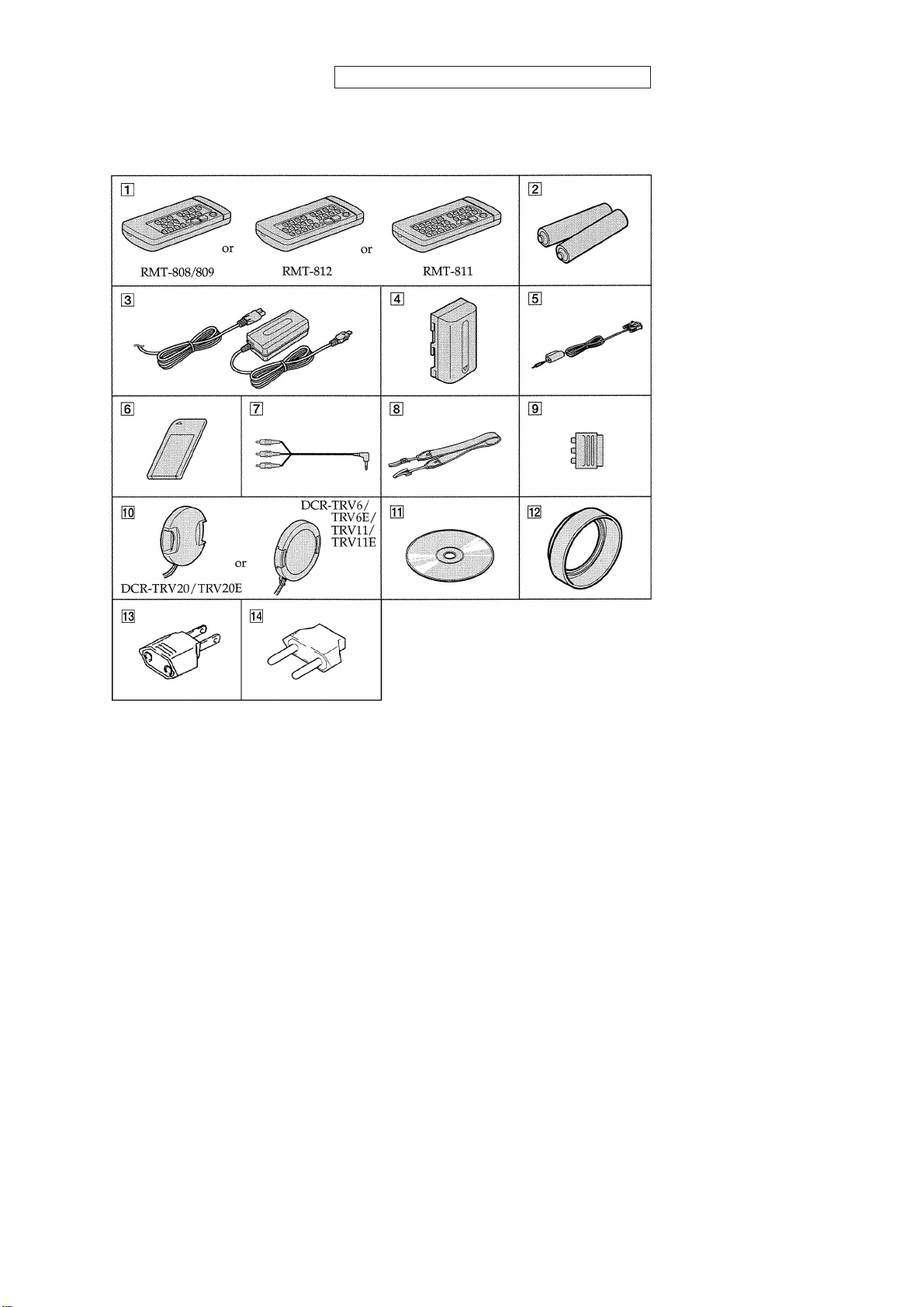
• SUPPLIED ACCESSORIES
Check that the following accessories are supplied with your
camcorder.
1 Wireless Remote Commander (1)
RMT-808: DCR-TRV6/TRV6E: AUS, E, JE, CN
RMT-809: DCR-TRV6E: AEP, UK
RMT-812: DCR-TRV11E: AEP, UK
RMT-811: DCR-TRV11/TRV11E: AUS, E, HK, JE, CN/TRV20/
TRV20E
2 R6 (size AA) battery for Remote Commander (2)
3 AC-L10A/L10B/L10C AC power adaptor (1),
Mains lead (1)
4 NP-FM50 battery pack (1)
5 PC serial cable (1)
DCR-TRV11/TRV11E/TRV20/TRV20E only
6 “Memory Stick” (1)
DCR-TRV11/TRV11E/TRV20/TRV20E only
7 A/V connecting cable (1)
8 Shoulder strap (1)
9 21-pin adaptor (1)
DCR-TRV6E: AEP, UK/TRV11E: AEP, UK/TRV20E: AEP, UK
0 Lens cap (1)
qa Application software: PictureGear 4.1Lite
(CD ROM) (1)
DCR-TRV11/TRV11E/TRV20/TRV20E only
qs Lens hood (1)
DCR-TRV20/TRV20E only
qd 2-pin conversion adaptor (1)
DCR-TRV6E: E, HK/TRV6E: E, HK/TRV11: E, HK/
TRV11E: E, HK/TRV20: E, HK/TRV20E: E, HK
qf 2-pin conversion adaptor (1)
DCR-TRV6: JE/TRV6E: JE/TRV11: JE/TRV11E: JE/
TRV20: JE/TRV20E: JE
• Abbreviation
CND : Canadian model
CN : Chinese model
HK : Hong Kong model
KR : Korea model
AUS : Australian model
JE : Tourist model
— 3 —
Page 4

Remark
DCR-
TR V20E
DCR-
TRV20E
DCR-
TRV20
DCR-
TRV11E
DCR-
TRV11E
DCR-
TRV11
DCR-
TRV6E
E, AUS,
HK, CN,
JE
AEP, UK
US,CND,
E,HK,JE,
KR
E, AUS,
HK, CN,
JE
AEP, UK
US,CND,
E, HK,
JE, KR
E, AUS,
HK, CN,
JE
NTSC: X101 is 66MHz (DCR-TRV20)
X701 is 36MHz (DCR-TRV6/TRV11)
PAL: X101 is 54MHz (DCR-TRV20E)
X701 is 36MHz (DCR-TRV6E/TRV11E)
PAL
PAL
NTSC
PAL
PAL
NTSC
PAL
RMT-811
RMT-811
RMT-811
RMT-811
RMT-812
RMT-811
RMT-808
1152H : with VC-240 board.
960H : with VC-241 board.
a: with IC1406 to IC1412 of VC-240 board
or with IC1402 to IC1407 of VC-241 board.
a: with REC button and IC903 of VC-240/241 board.
a
a
10×
120×
1152H
10×
40×
1152H
10×
120×
1152H
10×
120×
960H
a
a
a
a
a
a
a
a
a
a
3.5
3.5
3.5
3.5
246k
246k
246k
184k
TYPE CA, TYPE SH: with PD-123 board.
TYPE ST: with PD-124 board.
180k
TYPE ST
180k
TYPE ST
180k
TYPE CA
113k
a: with 1152H CCD imager.
a: with 960H CCD imager.
VC-240: with 1152H CCD imager.
VC-241: with 960H CCD imager.
CK-92: with LCD TYPE CA or TYPE SH.
CK-94: with LCD TYPE ST.
PD-123: with LCD TYPE CA or TYPE SH.
PD-124: with LCD TYPE ST.
a
CK-94
PD-124
a
VC-240
a
a
TYPE SH
CK-92
PD-123
a
a
10×
40×
960H
3.5
184k
113k
a
TYPE SH
a
a
a
10×
120×
960H
3.5
184k
113k
a
TYPE SH
VC-241
a
10×
120×
960H
2.5
200k
TYPE ST
113k
a
DCR-
TRV6E
AEP, UK
DCR-
TRV6
US,CND,
E, HK,
JE, KR
Model
Table for difference of function
Destination
PAL
10×
RMT-809
NTSC
Color system
10×
RMT-808
Remote commander
Lens
40×
960H
120×
960H
Digital zoom
CCD imager
MEMORY STICK slot
2.5
a
2.5
(RS232C)
DIGITAL I/O
LINE IN
LCD (size)
200k
TYPE ST
200k
TYPE ST
LCD (pixel)
LCD type
— 4 —
a
113k
a
113k
EVF (pixel)
CD-252 board
FP-219 flexible
CK-94
VC board
CK board
PD-124
PD board
KR : Korea model
AUS : Australian model
JE : Tourist model
CND : Canadian model
CN : Chinese model
HK : Hong Kong model
• Abbreviation
Page 5

TABLE OF CONTENTS
SERVICE NOTE
1. POWER SUPPLY DURING REPAIRS ····························· 8
2. TO TAKE OUT A CASSETTE WHEN NOT EJECT
(FORCE EJECT) ································································8
SELF-DIAGNOSIS FUNCTION
1. SELF-DIAGNOSIS FUNCTION······································· 9
2. SELF-DIAGNOSIS DISPLAY ·········································· 9
3. SERVICE MODE DISPLAY ············································· 9
3-1. Display Method ·································································· 9
3-2. Switching of Backup No. ··················································· 9
3-3. End of Display···································································· 9
4. SELF-DIAGNOSIS CODE TABLE································· 10
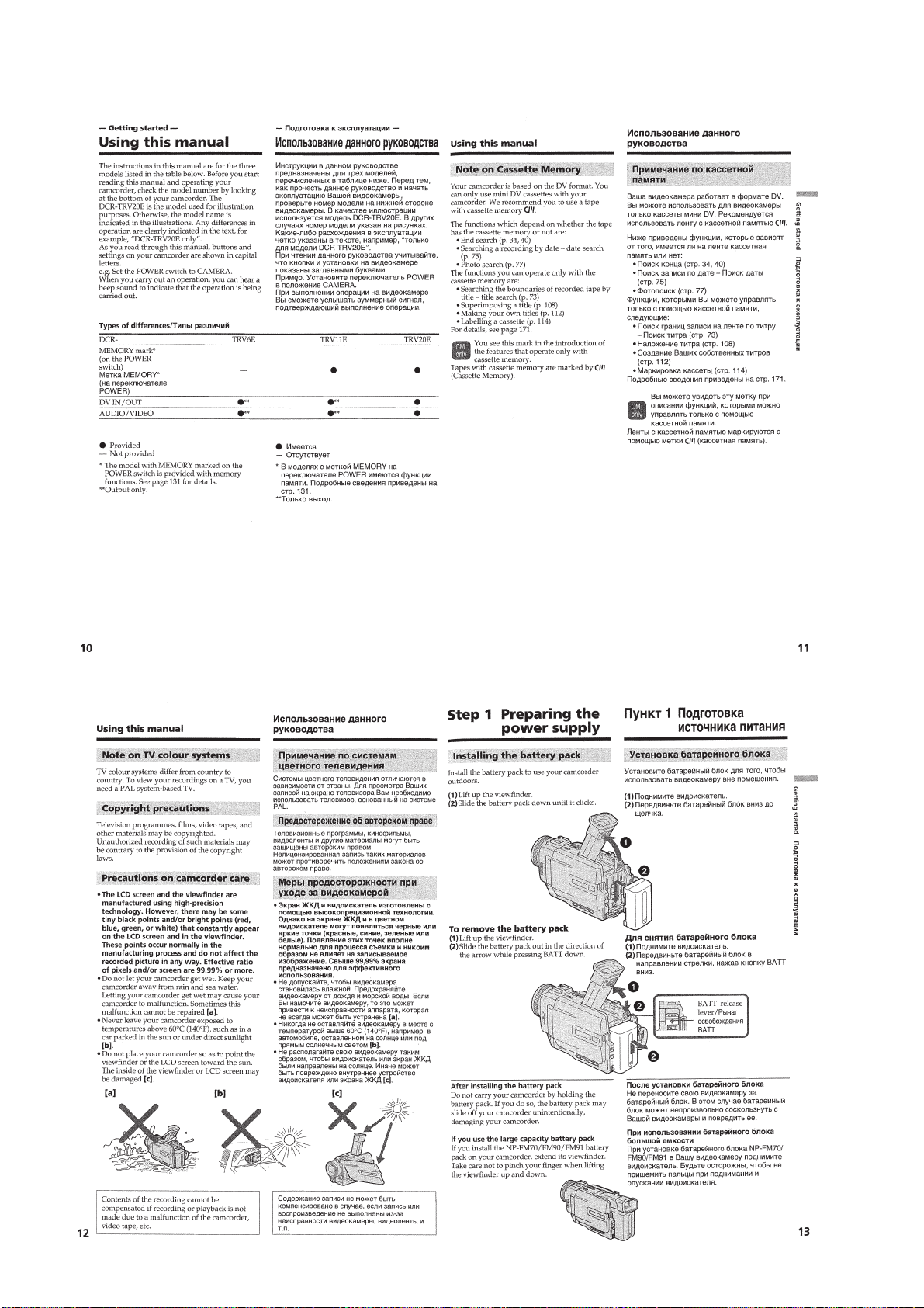
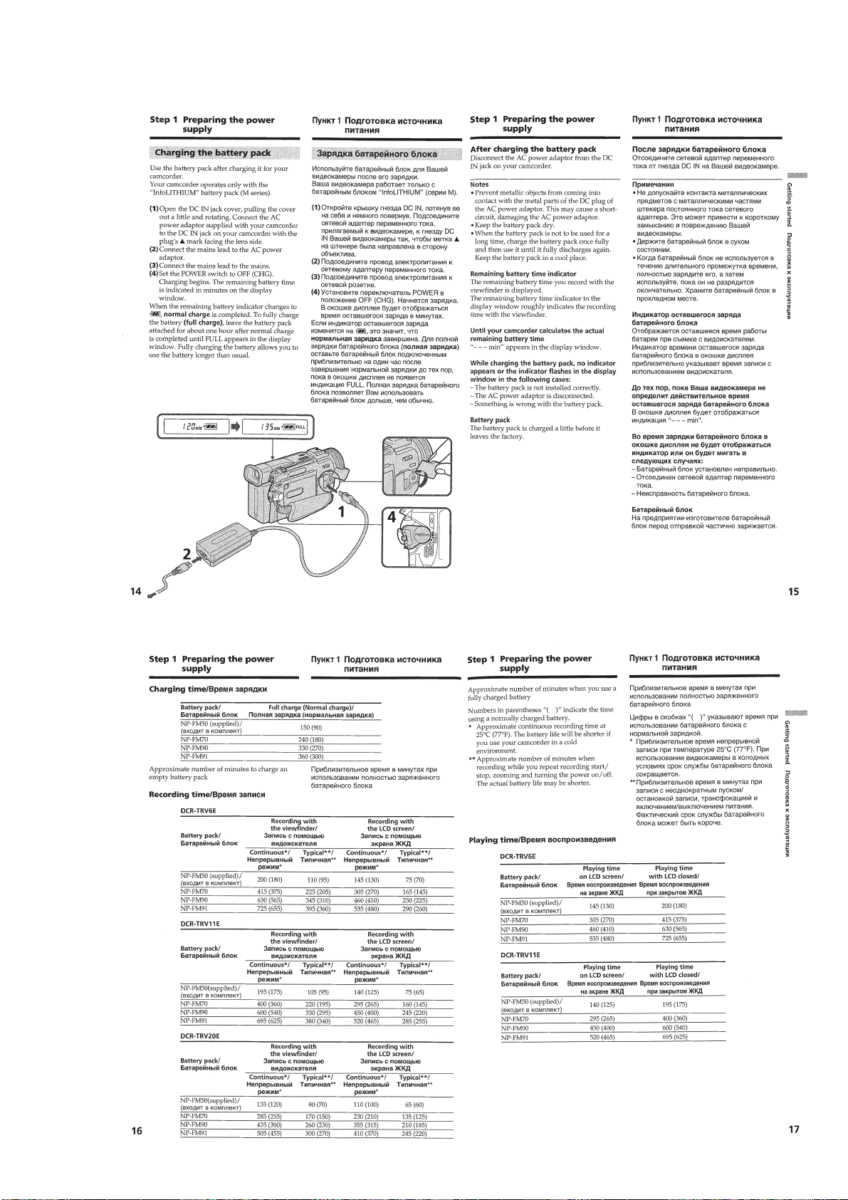
1. GENERAL
Checking supplied accessories ··················································1-1
Quick Start Guide ······································································ 1-1
Getting started ···········································································1-2
Using this manual ··································································1-2
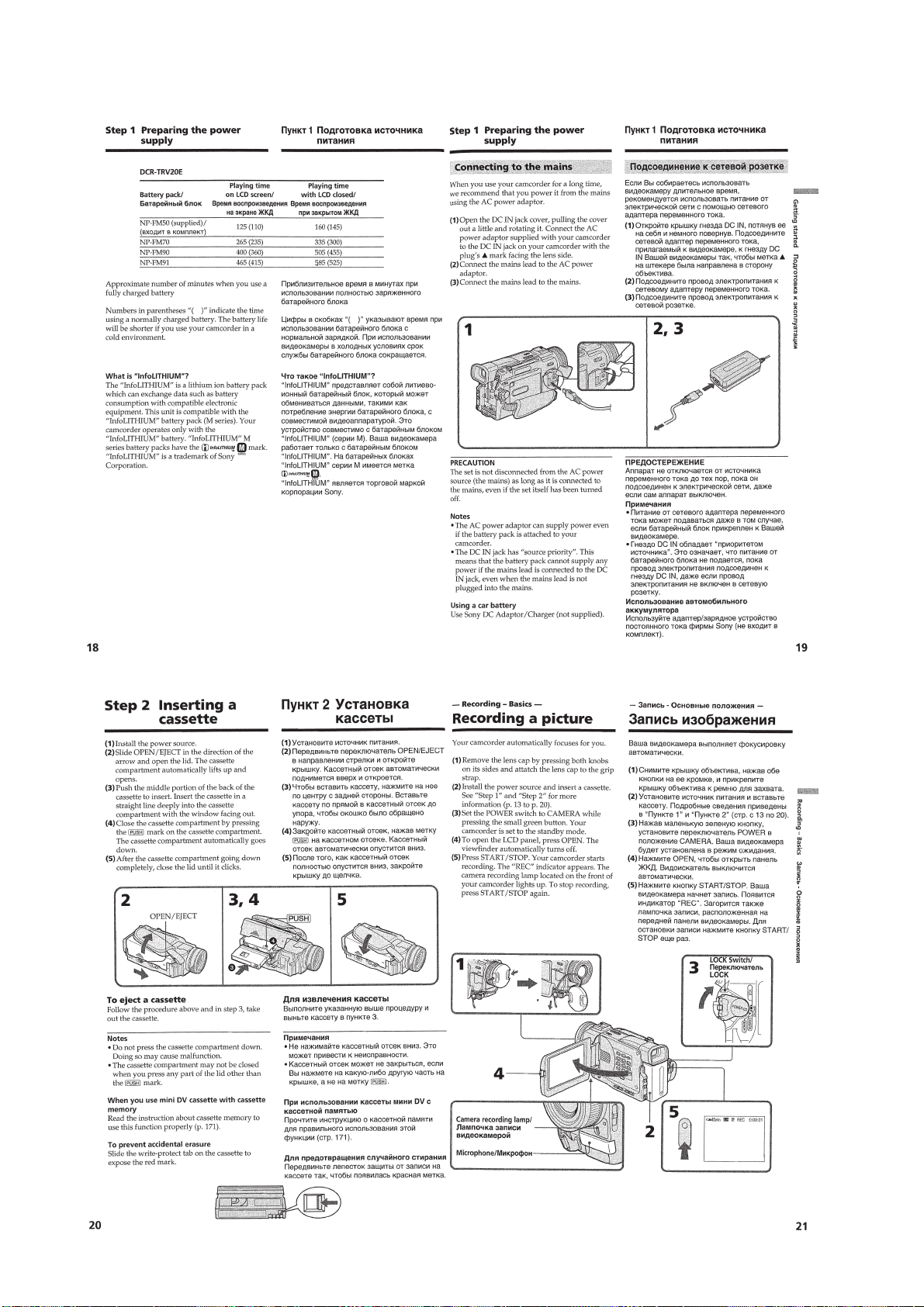
Step 1 Preparing the power supply ········································1-2
Installing the battery pack····················································1-2
Charging the battery pack ····················································1-3
Connecting to the mains ······················································1-4
Step 2 Inserting a cassette······················································1-4
Recording –Basics ····································································· 1-4
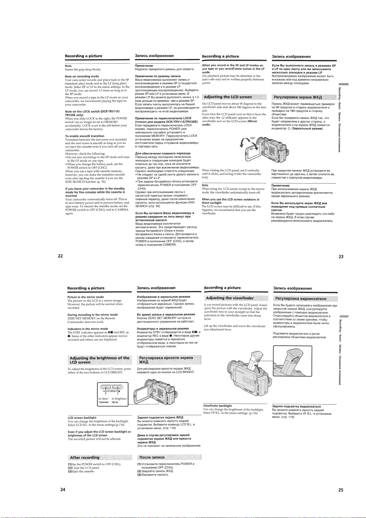
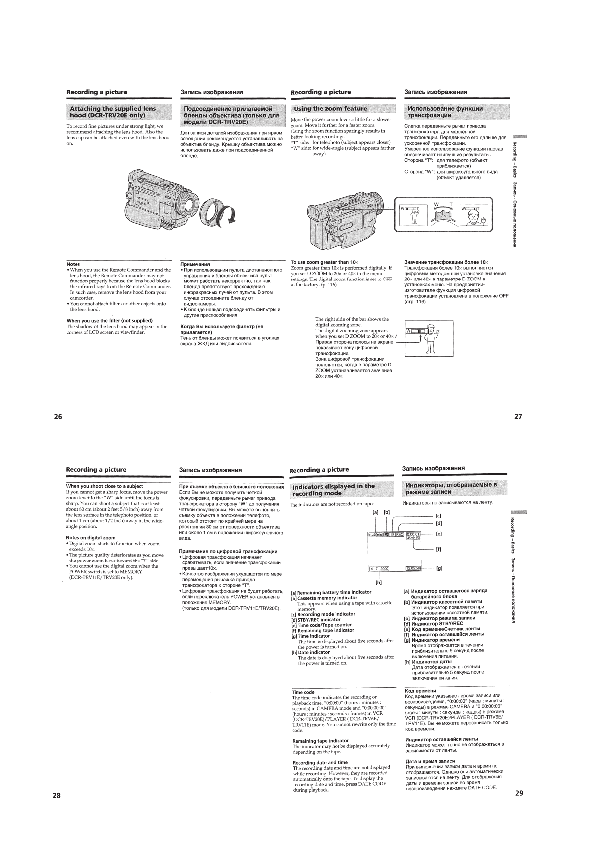
Recording a picture································································1-4
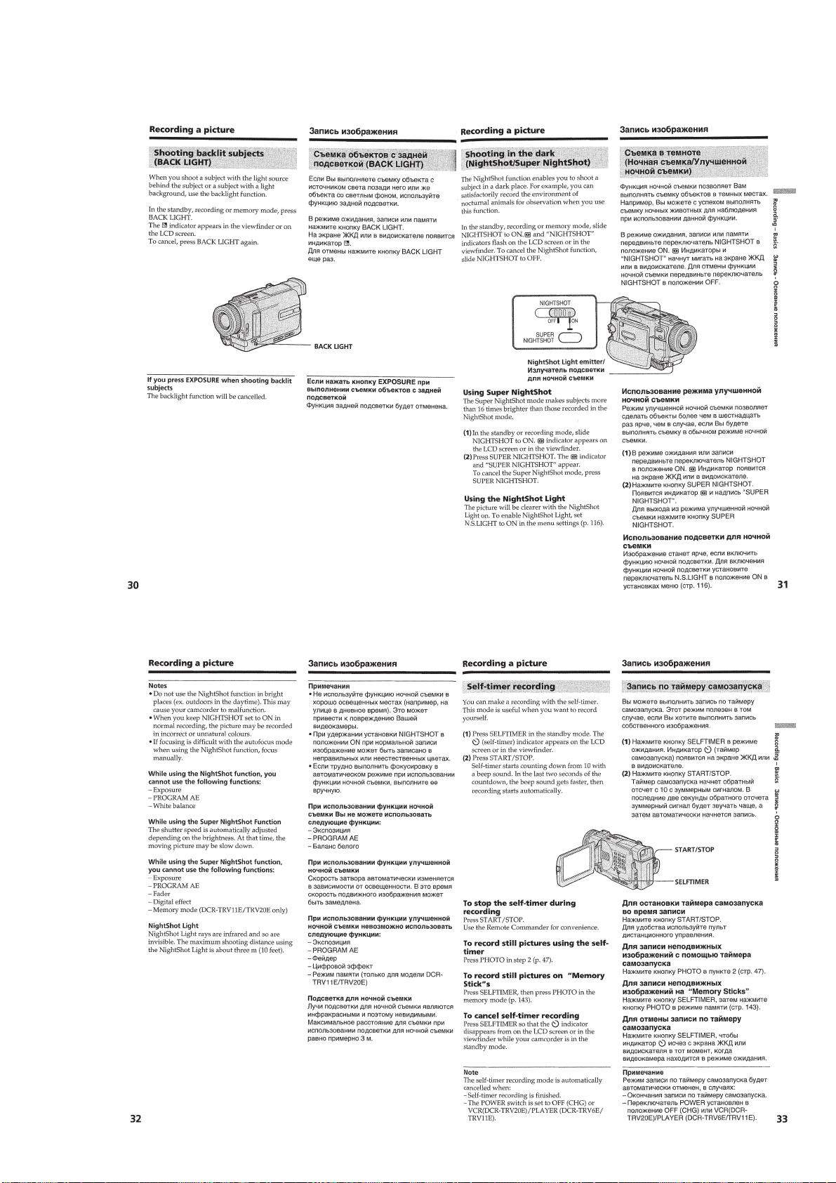
Shooting backlit subjects (BACK LIGHT)··························1-7
Shooting in the dark (NightShot/Super NightShot)·············1-7
Checking the recording – END SEARCH/
EDIT SEARCH/Rec Review ···············································1-8
Playback –Basics ······································································· 1-8
Playing back a tape ································································1-8
Viewing the recording on TV ················································1-9
Advanced Recording Operations············································· 1-10
Recording a still image on a tape –Tape Photo recording ···1-10
Adjusting the white balance manually································· 1-11
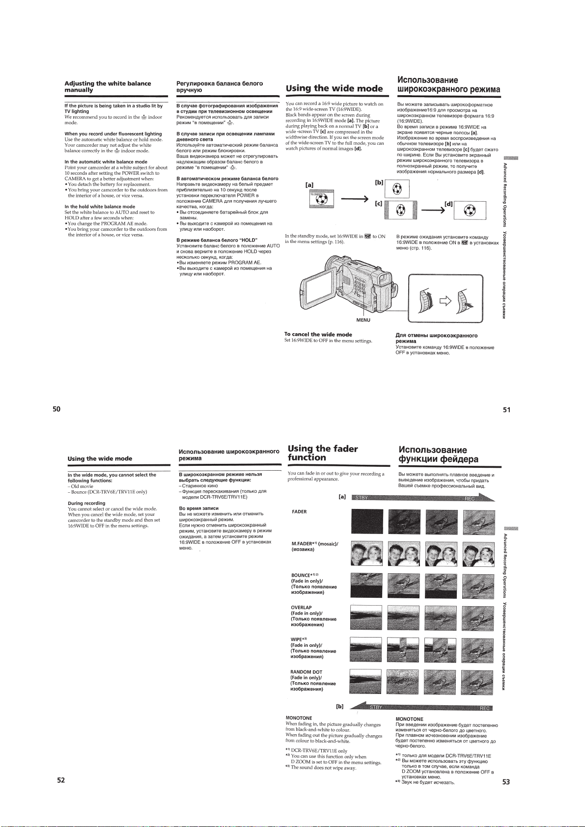
Using the wide mode ···························································1-12
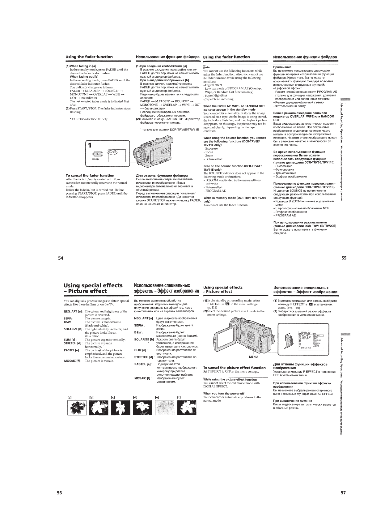
Using the fader function ······················································ 1-12
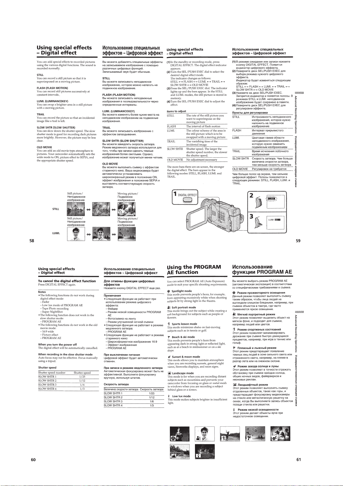
Using special effects –Picture effect····································1-13
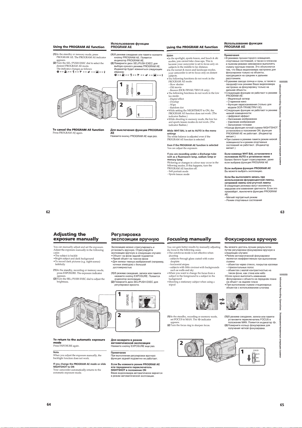
Using special effects –Digital effect····································1-14
Using the PROGRAM AE function ·····································1-14
Adjusting the exposure manually ········································ 1-15
Focusing manually·······························································1-15
Advanced Playback Operations··············································· 1-16
Playing back a tape with picture effects ······························1-16
Playing back a tape with digital effects ·······························1-16
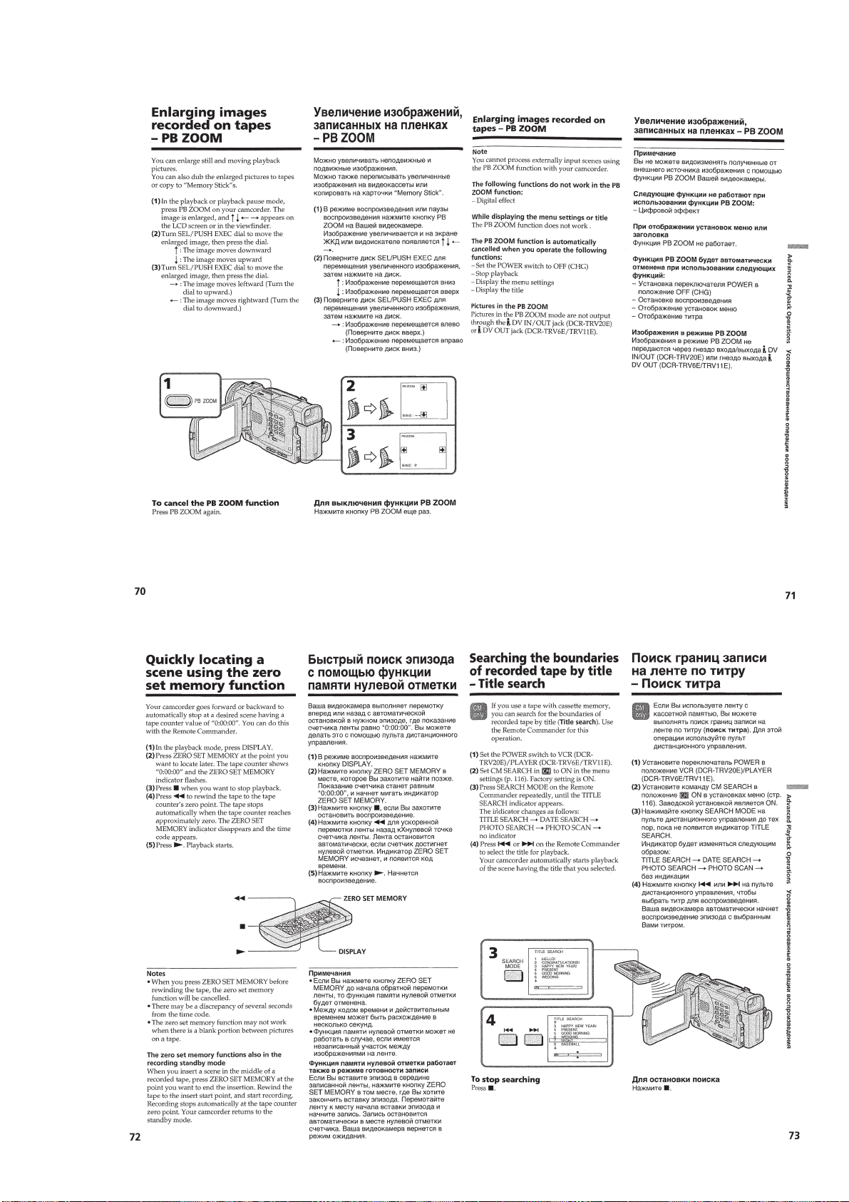
Enlaring images recorded on tapes –PB ZOOM ·················1-17
Quickly locating a scene using the zero set memory
function ················································································ 1-17
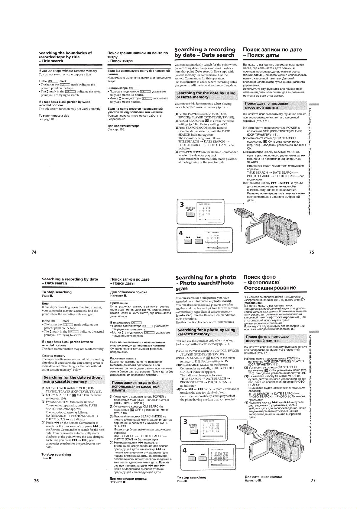
Searching the boundaries of recorded tape by title
–Title search·········································································1-17
Searching a recording by date –Date search························1-18
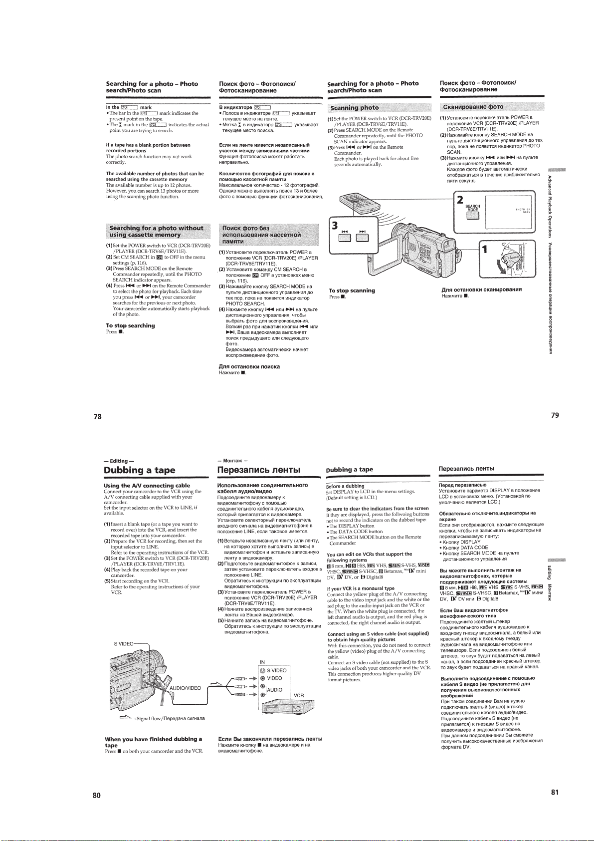
Searching for a photo –Photo search/Photo scan················· 1-18
Editing ·····················································································1-19
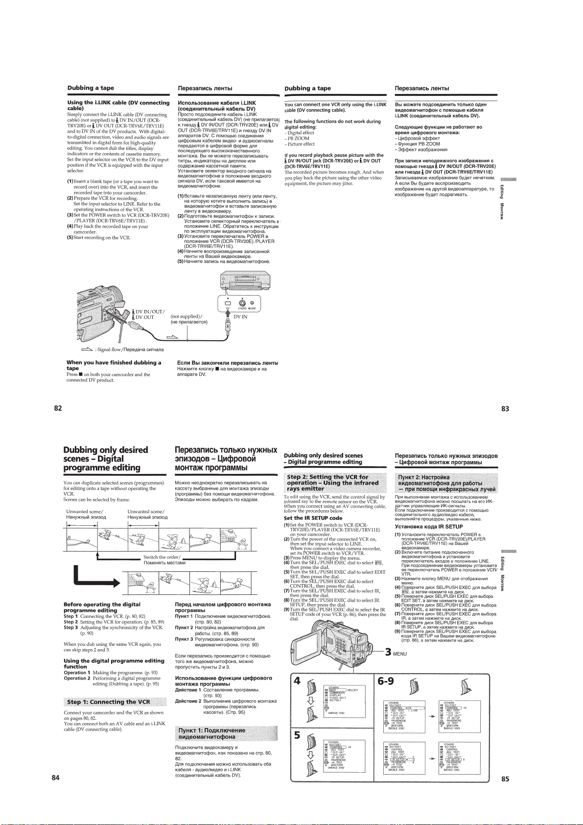
Dubbing a tape ·····································································1-19
Dubbing only desired scenes –Digital programme editing ···· 1-20
Using with analog video unit and PC
– Signal convert function·····················································1-23
Recording video or TV programmes ···································1-23
Inserting a scene from a VCR –Insert editing······················1-24
Audio dubbing ·····································································1-25
Superimposing a title ···························································1-26
Making your own titles ························································1-27
Labeling a cassette ·······························································1-28
Customizing Y our Camcorder ·················································1-28
Changing the menu settings·················································1-28
Resetting the date and time··················································1-30
“Memory Stick” Operations ···················································· 1-30
Using a “Memory Stick” –introduction ·······························1-30
Recording still images on “Memory Stick”s
–Memory photo recording ···················································1-32
Superimposing a still picture in a “Memory Stick”
on a moving picture –MEMORY MIX································1-34
Recording an image from a mini DV tape as a still image ··1-35
Copying still images from a mini DV tape –Photo save ······1-36
Viewing a still picture –Memory photo playback ················1-36
Copying the image recorded on “Memory Stick”s to
mini DV tapes ······································································ 1-37
Enlarging still images recorded on “Memory Stick”s
–Memory PB ZOOM ····························································
Playing back images in a continuous loop –SLIDE SHOW ···
Preventing accidental erasure –Image protection ················1-39
Deleting images ···································································1-39
Writing a print mark –PRINT MARK·································1-40
Additional Information ····························································1-40
Usable cassettes ···································································1-40
About i.LINK·······································································1-41
Troubleshooting ···································································1-42
Self-diagnosis display ··························································1-43
Warning indicators and messages ········································1-43
Using your camcorder abroad·············································· 1-44
Maintenance information and precautions···························1-44
Quick Reference ······································································1-45
Identifying the parts and controls ········································1-45
1-38
1-38
2. DISASSEMBLY
2-1. LCD SECTION-1 (TRV6/TRV6E MODEL)
(PD-124 BOARD, INVERTER TRANSFORMER UNIT,
INDICATION LCD BLOCK ASSEMBLY) ··················2-2
2-2. LCD SECTION-2
(TRV11/TRV11E/TRV20/TRV20E MODEL)
(PD-123/124 BOARD, INVERTER TRANSFORMER
UNIT, INDICATION LCD BLOCK ASSEMBLY) ········ 2-3
2-3. EVF SECTION (LB-64 BOARD)···································2-4
2-4. FRONT PANEL BLOCK ASSEMBLY
(MA-385 BOARD),
CABINET (R) BLOCK ASSEMBLY ·····························2-5
2-5. CK-92/94 BOARD, SPEAKER,
CONTROL SWITCH BLOCK (CF30150)·····················2-6
2-6. DD-137 BOARD, EVF BLOCK ASSEMBLY,
BT PANEL SECTION ····················································2-7
2-7. LENS SECTION-1
(LENS DEVICE, FP-219 FLEXIBLE BOARD)
(TRV6/TRV6E/TRV11/TRV11E MODEL) ····················2-8
2-8. LENS SECTION-2 (LENS DEVICE, CD-252 BOARD)
(TRV20/TRV20E MODEL) ············································ 2-8
2-9. VC-240/241 BOARD, MECHANISM DECK················2-9
2-10. CONTROL SWITCH BLOCK (FK30150)···················2-10
2-11. JK-188 BOARD, CONTROL SWITCH BLOCK
(PS30150) ······································································2-10
2-12. MEMORY STICK CONNECTOR
(TRV11/TRV11E/TRV20/TRV20E) ·····························2-11
HINGE ASSEMBLY, LCD HARNESS PROCESSING ·
2-13.
2-14. CIRCUIT BOARDS LOCATION·································2-13
2-15. FLEXIBLE BOARDS LOCATION ······························2-14
2-12
3. BLOCK DIAGRAMS
3-1. OVERALL BLOCK DIAGRAM (1/3)
(DCR-TRV6/TRV6E)······················································3-1
3-2. OVERALL BLOCK DIAGRAM (1/3)
(DCR-TRV11/TRV11E)··················································3-3
3-3. OVERALL BLOCK DIAGRAM (1/3)
(DCR-TRV20/TRV20E)··················································3-5
3-4. OVERALL BLOCK DIAGRAM (2/3) ···························3-7
— 5 —
Page 6

3-5. OVERALL BLOCK DIAGRAM (3/3) ···························3-9
3-6. POWER BLOCK DIAGRAM (1/2) ······························3-11
3-7. POWER BLOCK DIAGRAM (2/2)
(DCR-TRV6/TRV6E/TRV11/TRV11E) ························3-13
3-8. POWER BLOCK DIAGRAM (2/2)
(DCR-TRV20/TRV20E)················································3-15
4. PRINTED WIRING BOARDS AND
SCHEMATIC DIAGRAMS
4-1. FRAME SCHEMATIC DIAGRAM-1 ···························· 4-1
FRAME SCHEMATIC DIAGRAM-2 ····························4-3
4-2. PRINTED WIRING BOARDS AND
SCHEMATIC DIAGRAMS ············································ 4-5
• NS-10 (SUPER NIGHTSHOT SW)
PRINTED WIRING BOARD ·························4-6
• CD-252 (CCD IMAGER)
PRINTED WIRING BOARD ·························4-7
• CD-252 (CCD IMAGER)
SCHEMATIC DIAGRAM ····························4-11
• FP-219 FLEXIBLE BOARD (CCD IMAGER)
SCHEMATIC DIAGRAM ····························4-13
• FP-219 FLEXIBLE BOARD (CCD IMAGER)
PRINTED WIRING BOARD ·······················4-15
Shematic diagram and printed wiring board of the
VC-240/241 board are not shown.
Pages from 4-17 to 4-74 are not shown.
• CK-92 (KEY)
PRINTED WIRING BOARD ·······················4-75
• FP-181 FLEXIBLE BOARD (PANEL REVERSE)
PRINTED WIRING BOARD ·······················4-78
• CK-94 (KEY)
PRINTED WIRING BOARD ·······················4-79
• CK-92/94 (KEY)
SCHEMATIC DIAGRAM ····························4-83
• LB-64 (EVF BACK LIGHT)
PRINTED WIRING BOARD AND
SCHEMATIC DIAGRAM ····························4-85
• JK-188 (A/V IN/OUT)
PRINTED WIRING BOARD ·······················4-87
• JK-188 (A/V IN/OUT)
SCHEMATIC DIAGRAM ····························4-89
• CONTROL SWITCH BLOCK (FK-30150)
SCHEMATIC DIAGRAM ····························4-91
• PD-123 (LCD DRIVE, RGB DRIVE)
PRINTED WIRING BOARD ·······················4-92
• PD-123 (LCD DRIVE)(1/2)
SCHEMATIC DIAGRAM ····························4-93
• PD-123 (RGB DRIVE)(2/2)
SCHEMATIC DIAGRAM ····························4-95
• PD-124 (LCD DRIVE)(1/2)
SCHEMATIC DIAGRAM ····························4-97
• PD-124 (RGB DRIVE)(2/2)
SCHEMATIC DIAGRAM ····························4-99
• PD-124 (LCD DRIVE, RGB DRIVE)
PRINTED WIRING BOARD ·····················4-101
• SE-107 (MANUAL FOCUS)
PRINTED WIRING BOARD ·····················4-102
• MA-385 (AUDIO I/O)
PRINTED WIRING BOARD ·····················4-103
• MA-385 (AUDIO I/O)
SCHEMATIC DIAGRAM ··························4-105
• DD-137 (DC/DC CONVERTER)(1/2)
SCHEMATIC DIAGRAM ··························4-107
• DD-137 (DC/DC CONVERTER)(2/2)
SCHEMATIC DIAGRAM ··························4-109
• DD-137 (DC/DC CONVERTER)(1/2)
PRINTED WIRING BOARD ·····················4-111
4-3. WAVEFORMS ····························································4-113
4-4. MOUNTED LOCATION ············································4-125
5 ADJUSTMENTS
1. Before starting adjustment···············································5-1
1-1. Adjusting items when replacing main parts and boards. ···5-2
5-1. CAMERA SECTION ADJUSTMENT ···························5-6
1-1. PREPARATIONS BEFORE ADJUSTMENT
(CAMERA SECTION) ···················································5-6
1-1-1.List of Service Tools ························································5-6
1-1-2.Preparations ·····································································5-7
1-1-3.Precaution ········································································ 5-9
1. Setting the Switch···························································· 5-9
2. Order of Adjustments ······················································5-9
3. Subjects ···········································································5-9
1-2.
INITIALIZATION OF B, C, D, E, F, 7, 8 PAGE DATA ···
1-2-1.INITIALIZATION OF C, D, 8 PAGE DATA················5-10
1. Initializing the C, D, 8 Page Data··································5-10
2. Modification of C, D, 8 Page Data ································5-10
3. C Page Table ··································································5-10
4. D Page Table·································································· 5-12
5. 8 Page Table···································································5-13
1-2-2.INITIALIZATION OF B PAGE DATA
(DCR-TRV11/TRV11E/TRV20/TRV20E) ····················5-14
1. Initializing the B Page Data (DCR-TRV20/TRV20E) ··5-14
2. Modification of B Page Data (DCR-TRV20/TRV20E)··5-14
3. Initializing the B Page Data (DCR-TRV11/TRV11E) ··5-14
4. Modification of B Page Data (DCR-TRV11/TRV11E)··5-14
5. B Page Table ··································································5-15
1-2-3.INITIALIZATION OF E, F, 7 PAGE DATA ·················5-15
1. Initializing the E, F, 7 Page Data ··································· 5-15
2. Modification of E, F, 7 Page Data ·································5-15
3. F Page Table ··································································5-16
4. E Page Table ··································································5-18
5. 7 Page Table···································································5-19
1-3. CAMERA SYSTEM ADJUSTMENTS ························5-20
1. 36MHz Origin Oscillation Adjustment
(DCR-TRV6/TRV6E/TRV11/TRV11E)(VC-241 board) ··
2. 54MHz/66MHz Origin Oscillation Adjustment
(DCR-TRV20/TRV20E)(CD-252 board) ······················5-20
3. Zoom Key Center Adjustment ·······································5-21
4. HALL Adjustment
(DCR-TR V6/TR V6E/TRV11/TR V11E)························5-21
5. HALL Adjustment (DCR-TRV20/TR V20E)·················5-22
6. MR Adjustment (DCR-TRV20/TR V20E) ·····················5-22
7. Flange Back Adjustment
(Using Minipattern Box) ···············································5-23
8. Flange Back Adjustment
(Using Flange Back Adjustment Chart and
Subject More Than 500m Away)··································5-24
8-1. Flange Back Adjustment (1) ··········································5-24
8-2. Flange Back Adjustment (2) ··········································5-24
9. Flange Back Check························································5-25
10. Optical Axis Adjustment
(DCR-TR V6/TR V6E/TR V11/TRV11E)························5-26
11. Picture Frame Setting ····················································5-27
12. Color Reproduction Adjustment····································5-28
13. MAX GAIN Adjustment ··············································· 5-29
13-1. MAX GAIN Adjustment
(DCR-TRV6/TRV6E/TRV11/TRV11E) ························5-29
13-2. MAX GAIN Data Input (DCR-TRV20/TRV20E)·········5-29
14. Auto White Balance & LV Standard Data Input ···········5-29
15. Auto White Balance Adjustment ···································5-30
16. White Balance Check ····················································5-31
17. Mechanical Shutter Adjustment ····································5-31
5-10
5-20
— 6 —
Page 7

17-1. Mechanical Shutter Data Input
(DCR-TRV6/TRV6E/TRV11/TRV11E) ························5-31
17-2. Mechanical Shutter Data Input
(DCR-TRV20/TRV20E)················································5-32
18. Angular Velocity Sensor Sensitivity Adjustment ·········· 5-32
1-4. COLOR ELECTRONIC VIEWFINDER SYSTEM
ADJUSTMENT·····························································5-33
1. VCO Adjustment (VC-240/241 board) ·························5-33
2. RGB AMP Adjustment (VC-240/241 board) ················5-34
3. Contrast Adjustment (VC-240/241 board) ···················· 5-34
4. Backlight Consumption Current Adjustment
(VC-240/241 board) ······················································5-35
5. White Balance Adjustment (VC-240/241 board) ··········5-35
1-5. LCD SYSTEM ADJUSTMENT ···································5-36
1-5-1.LCD SYSTEM ADJUSTMENT
(DCR-TRV11/TRV11E/TRV20) ···································5-36
1. VCO Adjustment (PD-123 board)································· 5-36
2. RGB AMP Adjustment (PD-123 board)························5-37
3. Contrast Adjustment (PD-123 board)····························5-37
4. V-COM Level Adjustment (PD-123 board) ··················5-38
5. V-COM Adjustment (PD-123 board) ····························5-38
6. White Balance Adjustment (PD-123 board)··················5-39
1-5-2.LCD SYSTEM ADJUSTMENT
(DCR-TRV6/TRV6E/TRV20E)·····································5-39
1. VCO Adjustment (PD-124 board)································· 5-39
2. Bright Adjustment (PD-124 board) ·······························5-40
3. Black Limit Adjustment (PD-124 board) ······················5-40
4. Contrast Adjustment (PD-124 board)····························5-41
5. Center Level Adjustment (PD-124 board) ·····················5-41
6. V-COM Adjustment (PD-124 board) ····························5-42
7. White Balance Adjustment (PD-124 board)··················5-42
5-2. MECHANISM SECTION ADJUSTMENT··················5-43
2-1. HOW TO ENTER RECORD MODE WITHOUT
CASSETTE ···································································5-43
2-2. HO W TO ENTER PLAYBACK MODE WITHOUT
CASSETTE ···································································5-43
2-3. TAPE PATH ADJUSTMENT········································5-43
1. Preparation for Adjustment ···········································5-43
2. Procedure after operations·············································5-43
5-3. VIDEO SECTION ADJUSTMENTS ···························5-44
3-1. PREPARATIONS BEFORE ADJUSTMENTS ············5-44
3-1-1.Equipment Required ······················································5-44
3-1-2.Precautions on Adjusting···············································5-45
3-1-3.Adjusting Connectors ····················································5-46
3-1-4.Connecting the Equipment ············································5-46
3-1-5.Checking the Input Signals (Except AEP/UK model)···5-46
3-1-6.Alignment Ta pes····························································5-47
3-1-7.Input/Output Level and Impedance ······························· 5-47
3-2. SYSTEM CONTROL SYSTEM ADJUSTMENT········5-48
1. Initialization of B, C, D, E, F, 7, 8 Page Data ···············5-48
2. Serial No. Input ····························································· 5-48
2-1. Company ID Input·························································5-48
2-2. Serial No. Input ·····························································5-48
3. Battery End Check (VC-240/241 board)·······················5-50
3-3. SERVO AND RF SYSTEM ADJUSTMENT ···············5-51
1. Cap FG Duty Adjustment (VC-240/241 board) ············5-51
2. PLL f
0 & LPF f0 Adjustment (VC-240/241 board) ·······5-51
3. Switching Position Adjustment (VC-240/241 board) ···5-52
4. AGC Center Level and APC & AEQ Adjustment ·········5-52
4-1. Preparations before adjustments····································5-52
4-2. AGC Center Level Adjustment (VC-240/241 board)····5-52
4-3. APC & AEQ Adjustment (VC-240/241 board)·············5-53
4-4. Processing after Completing Adjustments ····················5-53
5. PLL f0 & LPF f0 Final Adjustment
(VC-240/241 board) ······················································5-53
3-4. VIDEO SYSTEM ADJUSTMENTS·····························5-54
3-4-1.Base Band Block Adjustments ······································5-54
1. Chroma BPF f
0 Adjustment (VC-240/241 Board) ········5-54
2. S VIDEO OUT Y Level Adjustment
(VC-240/241 Board)······················································5-54
3. S VIDEO OUT Chroma Level Adjustment
(VC-240/241 Board)······················································5-55
4. AV OUT Y, Chroma Level Check (
VC-240/241 Board
)·· 5-55
3-4-2.BIST Check ···································································5-56
1. Playback System Check ················································ 5-56
1-1. Preparations for Playback··············································5-56
1-2. IC301 TRX (RF) PB BIST Check·································5-56
1-3. IC301 AUD (ABUS) PB BIST Check···························5-56
1-4. IC301 VFD PB BIST Check ·········································5-56
1-5. IC301 ENCODER BIST Check ····································5-57
1-6. Processing after Completing Playback System Check··5-58
2. Recording System Check ·············································· 5-59
2-1. Preparations for recording ·············································5-59
2-2. IC301 TRX (RF) BIST Check·······································5-59
2-3. Processing after Completing Recording System Check ·· 5-59
3-5. IR TRANSMITTER ADJUSTMENTS·························5-60
1. IR Video Carrier Frequency Adjustment
(VC-240/241 board) ······················································5-60
2. IR Video Deviation Adjustment (VC-240/241 board) ···5-60
3. IR Audio Deviation Adjustment (VC-240/241 board) ··5-61
3-6. AUDIO SYSTEM ADJUSTMENTS ····························5-62
1. Playback Level Check ···················································5-63
2. Overall Level Characteristics Check ·····························5-63
3. Overall Distortion Check···············································5-63
4. Overall Noise Level Check············································5-63
5. Overall Separation Check·············································· 5-63
5-4. SERVICE MODE ··························································5-64
4-1. ADJUSTMENT REMOTE COMMANDER ················5-64
1. Using the adjustment remote commander ·····················5-64
2. Precautions upon using the adjustment remote
commander ····································································5-64
4-2. DATA PROCESS ···························································5-65
4-3. SERVICE MODE ··························································5-66
1. Setting the Test Mode ····················································5-66
2. Emergence Memory Address ········································5-66
2-1. EMG Code (Emergency Code) ·····································5-66
2-2. MSW Code ····································································5-67
3. Bit value discrimination ················································ 5-68
4. Switch check (1) ····························································5-68
5. Switch check (2) ····························································5-69
6. Record of Use check······················································5-69
6. REPAIR PARTS LIST
6-1-1.FRONT PANEL BLOCK ASSEMBLY AND
BATTERY PANEL SECTION ········································6-1
6-1-2.CABINET (R) BLOCK ASSEMBLY ·····························6-2
6-1-3.LCD BLOCK ASSEMBLY (TRV6/TRV6E MODEL)··· 6-3
6-1-4.LCD BLOCK ASSEMBLY
(TRV11/TRV11E/TRV20/TRV20E MODEL) ················6-4
6-1-5.CABINET (L) SECTION················································6-5
6-1-6.CABINET (L) SECTION-2 ············································6-6
6-1-7.LENS BLOCK ASSEMBLY AND
EVF BLOCK ASSEMBLY ·············································6-7
6-1-8.CASSETTE COMPARTMENT AND
DRUM BLOCK ASSEMBLY ········································· 6-8
6-1-9.LS CHASSIS ASSEMBLY ·············································6-9
6-1-10. MECHANISM CHASSIS BLOCK ASSEMBLY ······6-10
6-2. ELECTRICAL PARTS LIST ········································ 6-11
Parts list of the VC-240/241 board are not shown.
Pages from 6-23 to 6-44 are not shown.
* Optical axis frame and color reproduction frame are
shown on page 247 to 249.
— 7 —
Page 8
SERVICE NOTE
1. POWER SUPPLY DURING REPAIRS
In this unit, about 10 seconds after power is supplied to the battery terminal using the regulated po wer supply (8.4V), the power is shut of f so
that the unit cannot operate.
These following two methods are available to prevent this. Take note of which to use during repairs.
Method 1.
Connect the servicing remote commander RM-95 (J-6082-053-B) to the LANC jack, and set the commander switch to the “ADJ” side.
Method 2.
Use the DC IN terminal. (Use the AC power adaptor (AC-L10, AC-VQ800 etc. ))
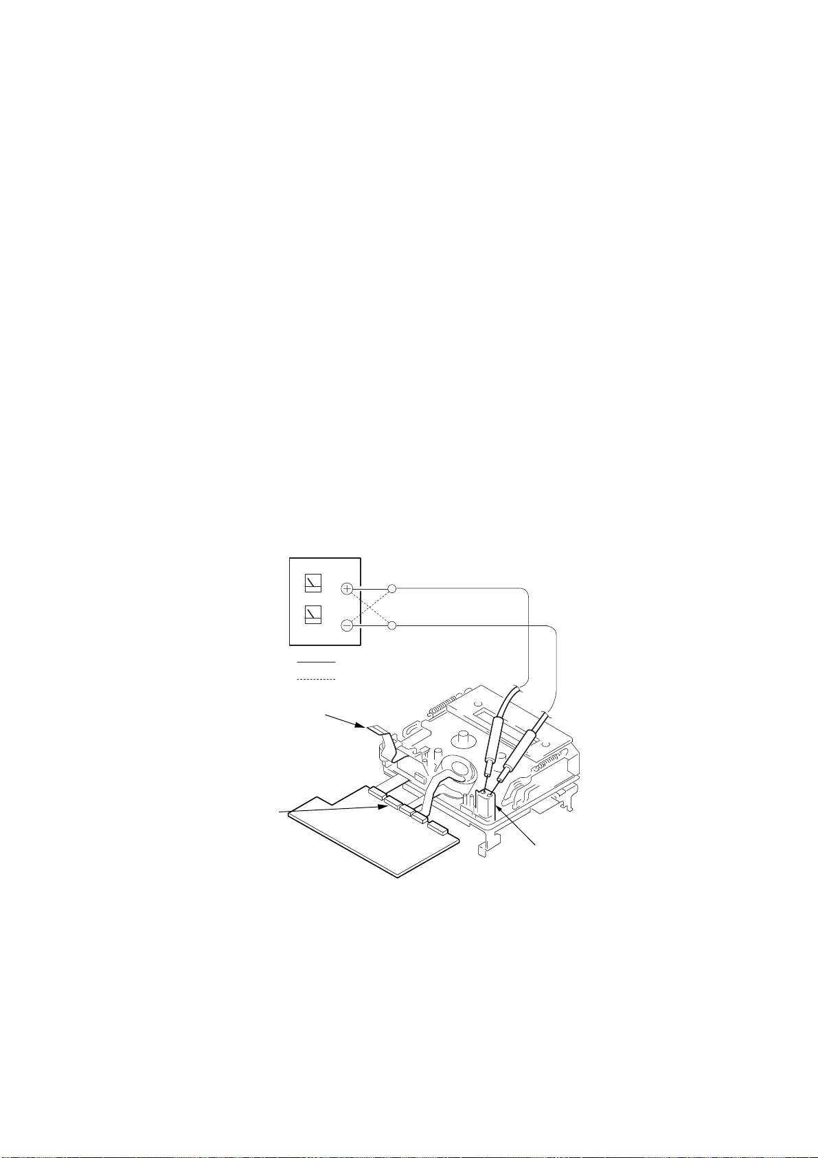
2. TO TAKE OUT A CASSETTE WHEN NOT EJECT (FORCE EJECT)
1 Refer to 2-4. to remove the top cabinet assembly.
2 Refer to 2-4. to remove the front panel block assembly.
3 Refer to 2-4. to remove the cabinet (R) block assembly.
4 Refer to 2-6. to remove the battery panel section.
5 Refer to 2-6. to remove the VC heat sink. (DCR-TRV20/TRV20E model only)
6 Refer to 2-6. to remove DD-137 board.
7 Open the VC-240/241 board.
8 Refer to 2-9. to remove the two screws (M1.7 × 2.5) with which the MD frame assembly is fixed on the CS frame assembly.
9 Refer to 2-9. to remove the mechanism deck and VC-240/241 board.
0 Remove the CN006 (27P 0.3 mm) of the VC-240/241 board.
qa Supply +4.5V from the DC power supply to the loading motor and unload with a pressing the cassette compartment.
DC power supply
(+4.5Vdc)
Disconnect from CN006 (27P)
of VC-240/241 board
CN006
VC-240/241 board
: Unloading
: Loading
Loading motor
— 8 —
Page 9
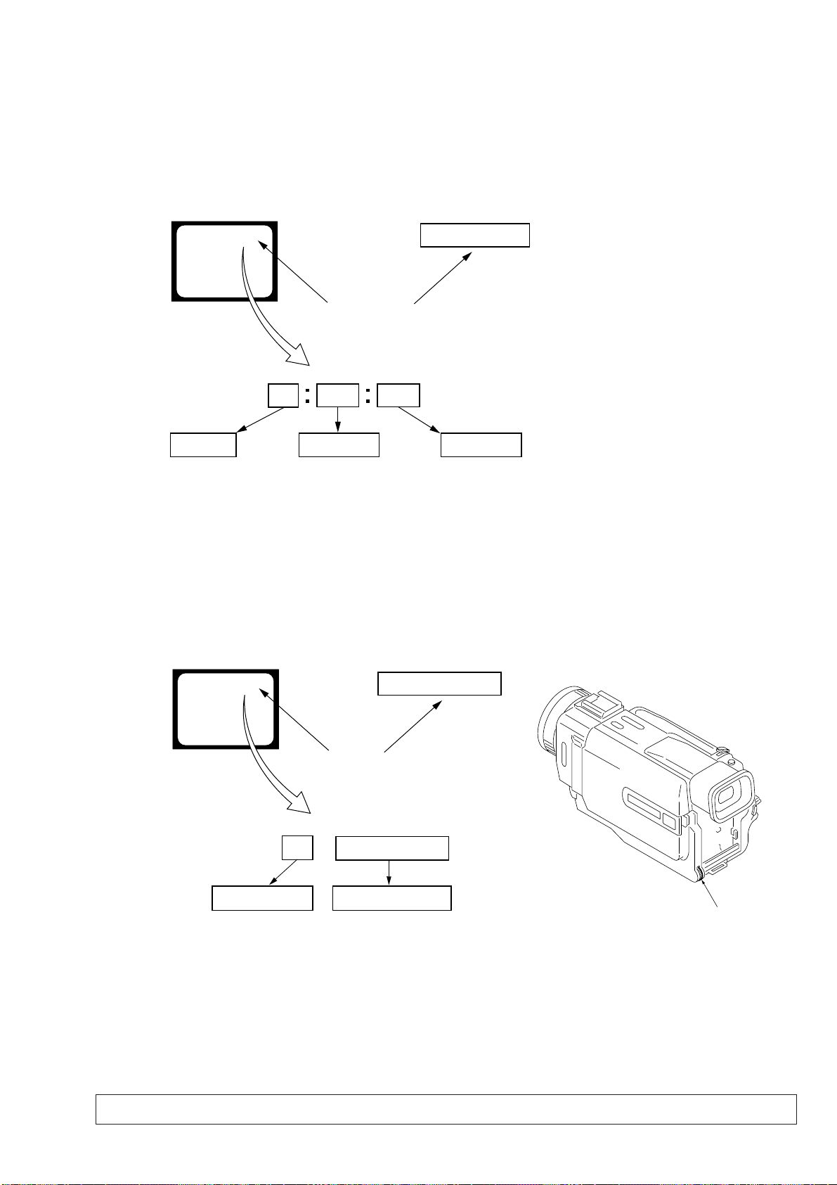
SELF-DIAGNOSIS FUNCTION
1. SELF-DIAGNOSIS FUNCTION
When problems occur while the unit is operating, the self-diagnosis
function starts working, and displays on the viewf inder, LCD screen
or LCD window what to do. This function consists of two display;
self-diagnosis display and service mode display.
Details of the self-diagnosis functions are provided in the Instruction
manual.
Viewfinder or LCD screen LCD window
C : 3 1 : 1 1
Blinks at 3.2Hz
1 1
Repaired by:
C : Corrected by customer
H : Corrected by dealer
E : Corrected by service
engineer
C
Indicates the appropriate
step to be taken.
E.g.
31 ....Reload the tape.
32 ....Turn on power again.
3 1
Block
2. SELF-DIAGNOSIS DISPLAY
When problems occur while the unit is operating, the counter of the
viewfinder, LCD screen or LCD window consists of an alphabet
and 4-digit numbers, which blinks at 3.2 Hz. This 5-character display
indicates the “repaired by:”, “block” in which the problem occurred,
and “detailed code” of the problem.
C : 3 1 : 11
Detailed Code
Refer to page 10.
Self-diagnosis Code Table.
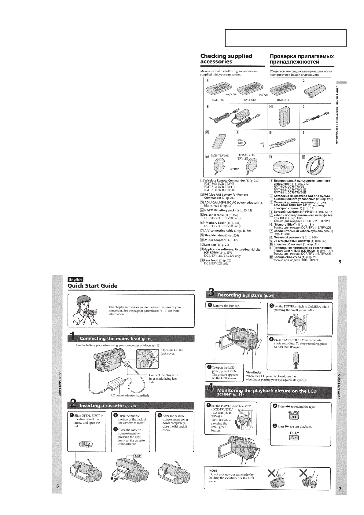
3. SERVICE MODE DISPLAY
The service mode display shows up to six self-diagnosis codes shown in the past.
3-1. Display Method
While pressing the “STOP” key, set the switch from OFF to “VCR or PLAYER”, and continue pressing the “STOP” key for 5 seconds
continuously. The service mode will be displayed, and the counter will show the backup No. and the 5-character self-diagnosis codes.
Viewfinder or LCD screen
[3] C : 3 1 : 1 1
Lights up
[3]
Backup No.
Order of previous errors
C : 3 1 : 1 1
Self-diagnosis Codes
3-2. Switching of Backup No.
By rotating the control dial, past self-diagnosis codes will be shown in order. The backup No. in the [] indicates the order in which the
problem occurred. (If the number of problems which occurred is less than 6, only the number of problems which occurred will be shown.)
[1] : Occurred first time [4] : Occurred fourth time
[2] : Occurred second time [5] : Occurred fifth time
[3] : Occurred third time [6] : Occurred the last time
LCD window
3 C : 3 1 : 11
Control dial
3-3. End of Display
Turning OFF the power supply will end the service mode display.
Note: The “self-diagnosis display” data will be backed up by the coin-type lithium battery of CK-92/94 board BT3201. When this coin-type lithium
battery is removed, the “self-diagnosis display” data will be lost by initialization.
— 9 —
Page 10

4. SELF-DIAGNOSIS CODE TABLE
Self-diagnosis Code
Repaired by:
C
C
C
C
C
C
C
C
C
C
C
C
C
C
C
C
C
C
C
C
C
C
C
E
E
E
E
Block
Function
04
21
22
31
31
31
31
31
31
31
31
31
31
31
31
32
32
32
32
32
32
32
32
61
61
62
62
Detailed
Code
00
00
00
10
11
20
21
22
23
24
30
40
42
10
11
20
21
22
23
24
30
40
42
00
10
00
01
Symptom/State
Non-standard battery is used.
Condensation.
Video head is dirty.
LOAD direction. Loading does not
complete within specified time
UNLOAD direction. Loading does not
complete within specified time
T reel side tape slacking when unloading
Winding S reel fault when counting the
rest of tape.
T reel fault.
S reel fault.
T reel fault.
FG fault when starting capstan.
FG fault when starting drum.
FG fault during normal drum operations.
LOAD direction loading motor time-
out.
UNLOAD direction loading motor
time-out.
T reel side tape slacking when
unloading.
Winding S reel fault when counting the
rest of tape.
T reel fault.
S reel fault.
T reel fault.
FG fault when starting capstan.
FG fault when starting drum
FG fault during normal drum
operations
Difficult to adjust focus
(Cannot initialize focus.)
Zoom operations fault
(Cannot initialize zoom lens.)
Steadyshot function does not work well.
(With pitch angular velocity sensor output
stopped.)
Steadyshot function does not work well.
(With yaw angular v elocity sensor output
stopped.)
Correction
Use the info LITHIUM battery.
Remove the cassette, and insert it again after one hour.
Clean with the optional cleaning cassette.
Load the tape again, and perform operations from the beginning.
Load the tape again, and perform operations from the beginning.
.
Load the tape again, and perform operations from the beginning.
Load the tape again, and perform operations from the beginning.
Load the tape again, and perform operations from the beginning.
Load the tape again, and perform operations from the beginning.
Load the tape again, and perform operations from the beginning.
Load the tape again, and perform operations from the beginning.
Load the tape again, and perform operations from the beginning.
Load the tape again, and perform operations from the beginning.
Remove the battery or power cable, connect, and perform
operations from the beginning.
Remove the battery or power cable, connect, and perform
operations from the beginning.
Remove the battery or power cable, connect, and perform
operations from the beginning.
Remove the battery or power cable, connect, and perform
operations from the beginning.
Remove the battery or power cable, connect, and perform
operations from the beginning.
Remove the battery or power cable, connect, and perform
operations from the beginning.
Remove the battery or power cable, connect, and perform
operations from the beginning.
Remove the battery or power cable, connect, and perform
operations from the beginning.
Remove the battery or power cable, connect, and perform
operations from the beginning.
Remove the battery or power cable, connect, and perform
operations from the beginning.
Inspect the lens block focus reset sensor (Pin 8,9 of CD-252 board
or Pin qk of CN3000 of FP-219 flexible board) when focusing is
performed when the control dial is rotated in the focus manual mode,
and the focus motor drive circuit (IC201 of VC-240/241 board) when
the focusing is not performed.
Inspect the lens block zoom reset sensor (
board or
is performed when the zoom lens is operated and the zoom motor
drive circuit (IC201 of VC-240/241 board) when zooming is not
performed.
Inspect pitch angular velocity sensor (SE3051 of JK-188 board)
peripheral circuits.
Inspect yaw angular velocity sensor (SE3052 of JK-188 board)
peripheral circuits.
Pin 9 of CN3000 of FP-219 flexible board) when zooming
Pin ql,w; of CD-252
— 10 —
Page 11
DCR-TRV6/TRV6E/TRV11/TRV11E/TRV20/TRV20E
SECTION 1
GENERAL
This section is extracted from instruction manual.
(DCR-TRV6E/TRV11E/TRV20E model)
1-1
Page 12
1-2
Page 13
1-3
Page 14
1-4
Page 15
1-5
Page 16
1-6
Page 17
1-7
Page 18
1-8
Page 19
1-9
Page 20
1-10
Page 21
1-11
Page 22
1-12
Page 23
1-13
Page 24
1-14
Page 25
1-15
Page 26

1-16
Page 27
1-17
Page 28
1-18
Page 29
1-19
Page 30
1-20
Page 31

1-21
Page 32

1-22
Page 33

1-23
Page 34

1-24
Page 35

1-25
Page 36

1-26
Page 37

1-27
Page 38

1-28
Page 39

1-29
Page 40

1-30
Page 41

1-31
Page 42

1-32
Page 43

1-33
Page 44

1-34
Page 45

1-35
Page 46

1-36
Page 47

1-37
Page 48

1-38
Page 49

1-39
Page 50

1-40
Page 51

1-41
Page 52

1-42
Page 53

1-43
Page 54

1-44
Page 55

1-45
Page 56

1-46
Page 57

1-47
Page 58

1-48E
Page 59

DCR-TRV6/TRV6E/TRV11/TRV11E/TRV20/TRV20E
SECTION 2
DISASSEMBLY
The following flow chart shows the disassembly procedure.
2-1. LCD section-1 (TRV6/TRV6E model)
(PD-124 board, Inverter transformer unit, Indication LCD block assembly)
DCR-TRV6/TRV6E/TRV11/TRV11E/TRV20/TRV20E
2-2. LCD section-2 (TRV11/TRV11E/TRV20/TRV20E model)
(PD-123/124 board, Inverter transformer unit, Indication LCD block assembly)
2-3. EVF section (LB-64 board)
2-4. Front panel block assembly (MA-385 board), Cabinet (R) block assembly
2-6. DD-137 board, EVF block assembly, BT panel section
2-7. Lens section-1 (Lens device, FP-219 flexible board) (TRV6/TRV6E/TRV11/TRV11E model)
2-8. Lens section-2 (Lens device, CD-252 board) (TRV20/TRV20E model)
2-9. VC-240/241 board, Mechanism deck
2-10. Control switch block (FK30150)
2-11. JK-188 board, Control switch block (PS30150)
[Connection diagram for service position (Mainly for voltage measurement and check)]
(MA-385, JK-188, CK-92/94, CD-252, FP-219 flexible, VC-240/241, DD-137 boards, Mechanism deck)
PD-123/124 board service position
(All model)
LB-64 board service position
MA-385, CK-92/94 boards
service position
MA-385, CK-92/94, DD-137 boards
service position
2-12. Memory stick connector
(TRV11/TRV11E/TRV20/TRV20E)
2-5. CK-92/94 board, Speaker, Control switch block (CF30150)
2-13. Hinge assembly, LCD harness processing
2-1
Page 60

NOTE: F ollo w the disassembly procedure in the numerical order given.
2-1. LCD SECTION-1 (TRV6/TRV6E MODEL)
(PD-124 BOARD, INVER TER TRANSFORMER UNIT,
INDICATION LCD BLOCK ASSEMBLY)
4
P cabinet (C) assembly
3
REMOVING THE PD-124 BOARD,
INVERTER TRANSFORMER UNIT,
INDICAITON LCD BLOCK ASSEMBLY
6
1
Liquid crystal indicator
module (24P)
8
Inverter transformer
unit (5P)
2
Back light
(Cold cathode fluorescent tube)
(15P)
qs
Release the
two claws, and
slide the indication
LCD block assembly
in the direction of
the arrow E.
(M1.7 × 2.5)
PD-124
Board
Screw
4
(PC-118) (12P)
3
(PC-119) (14P)
9
PD-124 board
5
FP-182 flexible
board (21P)
qf
Indication LCD
block assembly
qd
LCD holder
Harness
Harness
Four claws
2
T wo screws
(M1.7 × 4),
lock ace, p2
B
A
1
T wo screws
(M1.7 × 4), lock ace, p2
D
qa
PD-124
Board
7
Two tapping screws
(M1.7 × 3.5)
8
P frame (13)
5
T wo screws
(M1.7 × 2.5)
C
q;
Two claws
7
Two claws
E
qa
P frame assembly
B
A
Back light
9
Cold cathode
fluorescent tube
0
Liquid crystal
indicator module
D
C
6
P cabinet (M)
2-2
Page 61

2-2. LCD SECTION-2 (TRV11/TRV11E/TRV20/TRV20E MODEL)
PD-
Board
PD-
Board
PD-
Board
B
D
C
D
C
B
A
A
1
T wo screws
(M1.7 × 4), lock ace, p2
Screw (M1.7
×
4),
lock ace, p2
4
P cabinet (C) assembly
2
T wo screws
(M1.7 × 4),
lock ace, p2
5
Two screws
(M1.7 × 2.5)
3
Four claws
7
Two claws
q;
Two claws
qd
LCD holder
6
Screw
(M1.7 × 2.5)
6
P cabinet (M)
qa
P frame assembly
7
Liquid crystal
indicator module
Liquid crystal
indicator module
1
Liquid crystal indicator
module (24P)
5
FP-182 flexible
board (21P)
qf
Indication LCD
block assembly
Indication LCD
block assembly
E
9
4
Harness
(PC-118) (12P)
3
Harness
(PC-119) (14P)
8
Inverter transformer
unit (5P)
Inverter
transformer unit
9
PD-123 board
(TRV11/TRV11E/
TRV20 model)
PD-124 board
(TRV20E model)
PD-123 board (TRV11/TRV11E/TRV20 model)
PD-124 board (TRV6/TRV6E/TRV20E model)
CN009
12
19 20
CPC lid
CPC-8 jig
(J-6082-388-A)
DC IN
LANC jack
AC IN
AC POWER
ADAPTOR (8.4Vdc)
(AC-VQ800) or
(AC-L10)
8
Back light
Cold cathode
fluorescent tube
Back light
Cold cathode
fluorescent tube
2
Back light
(Cold cathode fluorescent tube)
(15P)
Adjustment remote
commander (RM-95)
REMOVING THE PD-123/124 BOARD,
INVERTER TRANSFORMER UNIT,
INDICAITON LCD BLOCK ASSEMBLY
[PD-123/124 BOARD SERVICE POSITION (ALL MODEL)]
qs
Release the
two claws, and
slide the indication
LCD block assembly
in the direction of
the arrow E.
(PD-123/124 BOARD, INVERTER TRANSFORMER UNIT ,
INDICATION LCD BLOCK ASSEMBLY)
2-3
Page 62

2-3. EVF SECTION (LB-64 BOARD)
1
Raise the finder in the
direction of the arrow A,
and slide it in the direction
of the arrow B.
A
B
REMOVING THE LB-64 BOARD
9
VF lens assembly
6
LCD (16P)
7
LB-64 board
2
Two tapping screws
(M1.7 × 5)
3
Two tapping screws
(M1.7 × 5)
2
VF cabinet (upper) assembly
1
Press down the
finder and release
the two claws.
4
VF cabinet
(lower) assembly
3
1
FP-180 flexible
board (27P)
3
LCD cushion (2)
2
Three claws
[LB-64 BOARD SERVICE POSITION]
VF lens assembly
AC POWER
AC IN
ADAPTOR (8.4Vdc)
(AC-VQ800) or
(AC-L10)
Adjustment remote
commander (RM-95)
8
LCD cushion (1)
5
LCD cushion (2)
4
BL illuminator
LB-64 board
CN009
1
CPC-8 jig
(J-6082-388-A)
2
DC IN
LANC jack
2-4
19
20
CPC lid
Screw (M1.7 × 4),
lock ace, p2
Page 63

2-4. FRONT PANEL BLOCK ASSEMBLY (MA-385 BOARD),
CABINET (R) BLOCK ASSEMBLY
1
of the arrow
qj
board (51P)
4
Top cabinet assembly
5
Screw (M1.7 × 4),
lock ace, p2
8
Screw (M1.7 × 4),
lock ace, p2
7
Open the
jack cover (DC)
and jack cover (S).
2
Screw (M1.7 × 4),
lock ace, p2
6
Screw (M1.7 × 4),
lock ace, p2
0
Front panel
block assembly
B
3
Claw
9
FP-188 flexible
board (28P)
qf
Press the eject knob in the
direction of the arrow
open the grip cabinet.
Eject knob
A
qh
Screw (M1.7 × 4),
lock ace, p2
C
and
C
Slide the finder in the direction
qd
lock ace, p2
FP-179 flexible
B
A
.
Screw (M1.7 × 4),
qa
Screw (M1.7 × 2.5),
lock ace, p2
qk
Cabinet (R) block assembly
qs
Screw (M1.7 × 2.5),
lock ace, p2
qg
lock ace, p2
Screw (M1.7 × 4),
Grip cabinet
REMOVING THE MICROPHONE UNIT, MA-385, SE-107 BOARD
7
SE-107 board
5
Three tapping screws
6
MA-385 board
1
2
(M1.7
3
Microphone retainer
4
Microphone unit
Three claws
T apping screw
×
3.5)
(M1.7
×
3.5)
2-5
Page 64

)
[MA-385, CK-92/94 BOARDS SERVICE POSITION]
AC POWER
AC IN
DC IN
ADAPTOR (8.4Vdc)
(AC-VQ800) or
(AC-L10)
Adjustment remote
commander (RM-95)
CPC-8 jig
(J-6082-388-A)
FP-179 flexible
board (51P)
CK-92 board
(TRV11/TRV11E/TRV20 model
CK-94 board
(TRV6/TRV6E/TRV20E model)
CN009
12
19 20
CPC lid
Screw (M1.7 × 4),
SE-107 board
MA-385 board
Microphone unit
JK-188 board
(28P)
CK-
Board
Cabinet (R) block assembly
lock ace, p2
2-5. CK-92/94 BOARD, SPEAKER, CONTROL SWITCH BLOCK (CF30150)
qh
C
Slant the bottom frame assembly,
tripod insulating sheet and tripod
table all three parts together,
in the direction of the arrow
C
and remove from the cabinet (R).
qs
Bottom frame
assembly
qd
Tripod insulating sheet
B
qf
T ripod (large)
T wo tapping
screws
(M1.7
×
3.5)
qj
Control switch block
(CF30150)
7
Four tapping
screws
(M1.7
×
3.5)
1
T wo tapping
screws
(M1.7
×
3.5)
5
Control switch block
(CF30150) (7P)
A
CK-
Board
A
2
Speaker retainer
assembly
3
(2P)
q;
(TRV11/TRV11E/TRV20 model)
CK-94 board
(TRV6/TRV6E/TRV20E model)
qg
Eject knob
B
Speaker
8
Two claws
CK-92 board
4
FP-181 flexible
board (6P)
6
Harness
(PC-118) (12P)
9
Harness
(PC-119) (14P)
qa
Three screws (M1.7 ),
lock ace, p2
with scotch grip.
2-6
Page 65

2-6. DD-137 BOARD, EVF BLOCK ASSEMBLY, BT PANEL SECTION
)
1
Two screws (M1.7 × 4),
lock ace, p2
2
BT panel section
7
8
CD-252 board (60P)
5
Screw (M1.7 × 2.5)
qs
connector (80P)
B
Board to board
EVF block assembly
4
Raise the finder
in the direction
of the arrow
A
.
VC-Board
DD-137
qa
(M1.7
qd
DD-137 board
9
(M1.7
q;
VC heat sink/VC rubber
(TRV20/TRV20E model)
[MA-385, CK-92/94, DD-137 BOARDS SERVICE POSITION]
EVF block assembly
B
Screw
×
2.5)
T wo screws
×
2.5)
FP-180 flexible board
(27P)
DD-137 board
A
6
Two tapping screws
(M1.7
3
FP-180 flexible board
(27P)
BT panel block assembly
×
5)
AC IN
DC IN
AC POWER
ADAPTOR (8.4Vdc)
(AC-VQ800) or
(AC-L10)
Adjustment remote
commander (RM-95)
Extension cable
(J-6082-395-A) (80P)
SE-107 board
MA-385 board
CD-252 board
(60P)
Microphone unit
VC-Board
JK-188 board
(28P)
CK-
DD-137
Board
FP-179 flexible board
(51P)
Board
CPC-8 jig
(J-6082-388-A)
CK-92 board
(TRV11/TRV11E/TRV20 model
CK-94 board
(TRV6/TRV6E/TRV20E model)
Cabinet (R) block assembly
2-7
Page 66

2-7. LENS SECTION-1 (LENS DEVICE, FP-219 FLEXIBLE BOARD)
(TRV6/TRV6E/TRV11/TRV11E MODEL)
8
Remove the
fourteen solderings
2
Control switch block
(FK30150) (8P)
5
DC-IN connector
1
FP-219 flexible board (50P)
4
Lens block
assembly
3
T wo tapping
screws (M1.7
2
Two tapping screws
(M1.7
5
(LSV-650B)
×
3.5)
A
Lens device
×
3.5)
3
FP-219 flexible
board (24P)
1
(M1.7
7
Seal rubber (W)
Screw
×
2.5)
A
qa
board
0
T apping screw
(M1.7
6
Optical filter block
4
T wo tapping
screws
(M1.7
FP-219 flexible
×
5)
9
CCD block
assembly
×
3.5)
2-8. LENS SECTION-2 (LENS DEVICE, CD-252 BOARD) (TRV20/TRV20E MODEL)
5
Remove the three
solderings
6
CD shield case
T apping screw
×
3.5)
4
T wo tapping
screws
(M1.7
qa
CD-252 board
9
CCD block assembly
2
Flexible board
(from Lens block)
(27P)
2
Control switch block
(FK30150) (8P)
5
DC-IN connector
1
CD-252 board
(60P)
3
Two tapping screws
(M1.7
4
Lens block
assembly
3
Two tapping screws
(M1.7
×
3.5)
×
3.5)
1
A
2
NS-10 board
4
Outer connector
(hot shoe)
lens frame
(M1.7
7
Screw
A
×
2.5)
REMOVING THE LENS DEVICE,
CD-252 BOARD
1
NS-10 board
(5P)
q;
CD sheet
8
Remove the
fourteen solderings
7
Seal rubber
(W)
6
Optical filter block
5
Lens device
(LSV-690A)
3
(M1.7
×
5)
2-8
Page 67

2-9. VC-240/241 BOARD, MECHANISM DECK
2
Control switch block
(FK30150) (39P)
1
JK-188 board
(60P)
3
T wo screws
(M1.7
×
2.5)
4
Mechanism deck,
MD frame assembly,
Cassette compartment cover
REMOVING THE VC-240/241 BOARD,
MECHANISM DECK
9
Two screws (M1.7 × 2.5),
lock ace, p2
qa
Mechanism
deck
2
Flexible board
(from capstan motor)
(27P)
3
FP-102 flexible board
(27P)
8
MD frame assembly
q;
Cassette
compartment cover
4
Flexible board
(from drum motor)
(10P)
D
C
B
A
7
Four screws
(M1.4
×
1.5)
VC-Board
5
Flexible board
(from video head)
(10P)
B
A
6
VC-240 board (TRV20/TRV20E model)
VC-241 board (TRV6/TRV6E/TRV11/TRV11E model)
4
D
C
VC-Board
1
FP-179 flexible
board (51P)
2
Two claws
VC-Board
1
T wo screws
3
VC-240 board
(M1.7
×
2.5)
(TRV20/TRV20E model)
VC-241 board
(TRV6/TRV6E/
TRV11/TRV11E model)
2-9
Page 68

2-10.CONTROL SWITCH BLOCK (FK30150)
)
4
FP-183 flexible
board (8P)
(TRV11/TRV11E/
TRV20/TR V20E model)
B
A
9
Control switch block
(FK30150)
CS frame assembly
REMOVING THE CONTROL SWITCH
BLOCK (FK30150), CS FRAME ASSEMBLY
4
Control switch block
(FK30150)
1
Screw
(M1.7
×
2.5)
5
Control switch block
(PS30150) (6P)
C
3
CS frame assembly
8
Remove 9 in the direction of the arrow
while taking care not to be caught by other parts.
6
Four tapping screws
(M1.7
B
A
×
3.5)
2
Claws
7
Two tapping screws
(M1.7
C
3
Zoom cover
×
3.5)
1
Screw
(M1.7
×
2.5
2
Dowel
2-11.JK-188 BOARD, CONTROL SWITCH BLOCK (PS30150)
REMOVING THE JK-188 BOARD
1
2
Screw
(M1.7
×
2.5)
3
Screws
(M1.7
Jack frame
×
2.5)
4
JK-188
board
2
JK-188 board
jack frame
3
T apping screw
(M1.7
4
Control switch block
(PS30150)
1
T apping screw
,
(M1.7
×
3.5)
×
3.5)
PRECAUTION DURING
INSTALLATION
To attach, align the
switch position as shown.
2-10
Page 69

[Connection diagram for service position (Mainly for voltage measurement and check)]
)
(MA-385, JK-188, CK-92/94, CD-252, FP-219 FLEXIBLE, VC-240/241, DD-137 BOARDS, MECHANISM DECK
Control switch block
(PS30150) (6P)
EVF block assembly
FP-180 flexible board
(27P)
DD-137 board
DD-137
Board
BT panel section
Control switch block
(FK30150) (39P)
(TRV20/TRV20E model)
NS-10 board
Lens block
assembly
(TRV6/TRV6E/TRV11/TRV11E)
Lens block assembly
FP-219 flexible board (50P)
Adjustment remote
commander (RM-95)
SE-107 board
MA-385 board
CD-252 board
(60P)
Microphone unit
(28P)
Mechanism deck
VC-
(60P)
VC-240 board
(TRV20/TRV20E model)
VC-241 board
(TRV6/TRV6E/TRV11/TRV11E model)
JK-188 board
Board
DC-IN connector
Extension cable
(J-6082-395-A) (80P)
FP-179 flexible board
(51P)
CK-
Board
Cabinet (R) block assembly
AC POWER
ADAPTOR (8.4Vdc)
(AC-VQ800) or
(AC-L10)
CK-92 board
(TRV11/TRV11E/TRV20 model)
CK-94 board
(TRV6/TRV6E/TRV20E model)
AC IN
CPC-8 jig
(J-6082-388-A)
2-12.MEMORY STICK CONNECTOR (TRV11/TRV11E/TRV20/TRV20E)
Perform the disassembling after steps 1 – 4 of 2-10 is complete.
5
3
2
FP-183 flexible board
Be careful not to be
caught by other parts.
9
Remove the MS chassis assembly
in the direction of the arrow
1
Screw
(M1.7
×
2.5)
6
Release the two
engaged portions.
Open it.
7
Remove the MS led assembly
in the direction of the arrow
B
C
.
A
4
Push it in the direction of the arrow A.
B
.
q;
qa
C
Remove the
eleven solderings.
8
Tapping screw
(M1.7
qd
Memory stick connector
qs
FP-183 flexible board
×
3.5)
2-11
Page 70

2-13.HINGE ASSEMBLY, LCD HARNESS PROCESSING
Start repair work after removing LCD by performing steps 1 – 6 of 2-1 or 2-2 and remove the CK-92/94 board by
performing steps 1 – 0 of 2-5.
q;
2
FP-181 flexible board
Be careful not to be
caught by other parts.
1
Two screws (M1.7)
with scotch grip
Hinge assembly
8
Screw
×
2.5)
5
Hinge cover (front)
3
Harness (PC-119) (14P)
Be careful not to be
caught by other parts.
4
Harness (PC-118) (12P)
Be careful not to be
caught by other parts.
5
(M1.7
9
FP-181
flexible board
PRECAUTION DURING INSTALLATION (LCD HARNESS PROCESSING)
3
Two claws
7
(PC-119) (14P)
1
Two screw (M1.7 × 4),
lock ace, p2
4
Hinge cover (rear)
2
Screw (M1.7 × 4),
lock ace, p2
6
(PC-118) (12P)
Harness
Harness
Create an extra length
to allow opening and closing.
Extra length is not
required in LCD.
PDBoard
Be careful thet harness must not
protrude from upper and lower side.
CKBoard
Allow extra length of
this extent in the cabinet.
2-12
Page 71

2-14.CIRCUIT BOARDS LOCATION
CD-252
(TRV20/TRV20E model)
(CCD IMAGER)
NS-10
(TRV20/TRV20E model)
(SLOW SHUTTER)
LB-64
(EVF BACK LIGHT)
DD-137
(DC/DC CONVERTER)
JK-188
(AV IN/OUT)
VC-240 (TRV20/TRV20E model)
VC-241 (TRV6/TRV6E/TRV11/TRV11E model)
A/D CONV, LENS DRIVER,
CAMERA CONTROL,
DV SIGNAL PROCESS,
REC/PB AMP, DS CONTROL,
JPEG, LINE IN/OUT, IR,
DRUM/CAPSTAN MOTOR DRIVE,
MECHANISM CONTROL,
HI CONTROL, AUDIO I/O
MA-385
(AUDIO I/O)
INVERTER TRANSFORMER
UNIT
PD-123 (TRV11/TRV11E/TRV20),
PD-124 (TRV6/TRV6E/TRV20E)
(LCD DRIVE, RGB DRIVE)
SE-107
(MANUAL FOCUS)
CK-92 (TRV11/TRV11E/TRV20 model)
CK-94 (TRV6/TRV6E/TRV20E model)
(KEY)
2-13
Page 72

2-15.FLEXIBLE BOARDS LOCATION
)
CONTROL SWITCH BLOCK
(FK30150)
CONTROL SWITCH BLOCK
(CF30150)
FP-183
(TRV11/TRV11E/TRV20/TRV20E)
CONTROL SWITCH BLOCK
(PS30150)
FP-181
FP-182
FP-180
(From LENS BLOCK)
(TRV20/TRV20E model)
FP-219
(TRV6/TRV6E/TRV11/TRV11E)
(CCD IMAGER)
FP-228
FP-100
FP-179
FP-102
From T OP/END SENSOR,
TAPE LED
(From VIDEO HEAD)
(From LENS BLOCK)
(TRV6/TRV6E/TRV11/TRV11E model)
(From DRUM MOTOR)
(From CAPSTAN MOTOR
2-14E
Page 73

SECTION 3
BLOCK DIAGRAMS
DCR-TRV6/TRV6E/TRV11/TRV11E/TRV20/TRV20E
3-1. OVERALL BLOCK DIAGRAM (1/3) (DCR-TRV6/TRV6E)
IC3000
1-4 10-13
+,-
+,-
(4-13)
CCD
IMAGER
•
49
49
48
48
42
42
44
44
31
31
35
35
38
38
25
28
28
(FLEXIBLE)(1/2)
8
6
V DRAIN
V1-V4,VSHT
H1,H2,RG
(4-27)
IC202
IC203
IRIS DRIVE
IRIS HALL AMP
2
4
FOCUS MOTOR
DRIVE
23
21
5
7
ZOOM MOTOR
DRIVE
17
19
IRIS
METER
FOCUS
MOTOR
LENS ASSY
(SHUTTER)
FP-219
IRIS
CN3000
IRIS DRIVE
M
M
M
H
FOCUS
RESET
SENSOR
1
2
IRIS HALL
6
4
18
FC A,B
FC XA,XB
11
14
ZM A,B
ZM XA,XB
21
24
IC204
ZOOM
MOTOR
ZOOM
RESET
SENSOR
NIGHT SHOT
JK-188 BOARD(1/3)
SE3052
YAW SENSOR
SE3051
PITCH SENSOR
9 49
20
CN3001
39
39
30
30
CN701
(4-89)
CN001
12
8
IC3051
YAW/PITCH
SENSOR
AMP
CN3001
18
58
58
57
57
SE-94 BOARD
MANUAL
FOCUS
SENSOR
CN2001
1
MIC
L
MIC
R
J2001
MIC
J2002
LANC
35
IC2002
3
MIC AMP
1
R
3
L
33
(4-105)
LANC SIG
CN2051
1
2
L
22
R
14
36
48
CN2701
11
11
11
10
10
10
3
3
3
1
1
1
5
5
5
26
26
26
CN3001
(4-28)
MF A,B
17
17
6
6
1
1
5
5
9
9
11
11
13
13
X701
36MHz
X801
20MHz
YAW AD
PITCH AD
VC-241 BOARD(1/3)
CN701
CCD OUT
18
IC702
21
TIMING
22
GENERATOR
25
33
4
5
(4-25)
(4-29)
IC801
EEPROM
14
22
23
40
41
58
59
ENO,DIR OA,DIR OB
ENI,DIR 1A,DIR 1B
FC RST
ZM RST
(4-29)
IC802
CAMERA CONTROL
9
12
13
16
(SEE PAGE
3-10)
TO
OVERALL
BLOCK DIAGRAM
(3/3)
(4-25)
IC701
30
(GCAM3)
S/H,AGC
A/D CONV.
19
CLPDM,PBLK
XSHP,XSHD
1
2
15
16
12
44
45
35
37
38
IRIS PWM
I HALL AD
4
3
2
IRIS PWM
43
I HALL AD
66
33
34
CAM SO,SI,SCK
35
AD SO,AD SCK
53
54
ZOOM AD
62
48
|
50
HI SO,SI,SCK
SHOE MIC L
SP+,-
ZOOM AD
OSD CS,SO,SCK
PANEL R,G,B,EVF R,G,B,HD,VD
IR V,IR L,IR R
LANC SIG
2
AD0-AD9
|
11
AD SO
AD SCK
47
48
16
23
AD CLK
( ) : Page No. shown in ( ) indicates the page to refer on the schematic diagram.
138
X301
24.576MHz
(4-33)
(CAIN)
DV SIGNAL
PROCESS
(ALIGN)
A/D CONV.
63-66
139
142
145
51
141
152
153
156
133
132
127
99
97
83
6
88
81
79
170
179
159
161
PANEL G
75
PANEL R
73
PANEL B
71
105
HD,VD
•
106
EVF G
67
EVF R
65
EVF B
63
55
59
2
6
V DRAIN
CLP OB
HD,VD
(4-31)
131
IC751
|
121
(BIRDS+)
CAMERA
PROCESS,
FOCUS/ZOOM
CONTROL,
EVR
112
115
CL
46
110
111
68
Y0-Y7
|
61
59
C0-C3
|
56
70
HD,VD,OE
71
72
30
42
Y0-Y7
C0-C3
HD,VD OE
C4-C7
SPCK
AFCK(IC903)
SPCK(IC751)
IR FSC
(4-36)
52
50
139
140
141
142
143
144
137
138
IC302
HI SO,SI SCK
CHARACTER
GENERATOR
1
3
OSD CS
OSD SO
OSD SCK
8
20
•
19
18
•
17
•
16
•
14
SPCK
(IC751)
AFCK
Y0-Y7
C0-C7
HD,VD,OE
EXCEPT
AEP/UK MODEL
199
201
205
203
211
207
215
213
1
IC301
3
5
7
17
21
23
9
11
13
15
182
196
48
HD
184
VD
•
183
COL0
195
•
|
194
COL3
•
191
•
190
(4-48)
31
•
68
IC903
34
59
|
52
49
|
47
38
37
36
L BUS
TRCK
LCK
FRRV,TRRV,TRRT
DATA TO SFD
DATA FROM SFD
SFD BCK
Y
C
45
42
47
49
(4-36)
IC361
(LIP)
DV INTERFACE
Y
C
DATA FROM SFD
DATA TO SFD
SFD BCK
46
7
36
34
10
IC1301
(TAKO)
LINE OUT
LINE IN
(4-50)
9
8
12
TPA+,-
6
TPB+,-
9
29
37
11
•
AGC
ACC
VSP SO,SCK
IC1002
(ADC&DAC)
D/A CONV.
A/D CONV.
MC BUS
(4-64)
J3004
DV IN/OUT
CN001
CN3001
39
39
42
42
REC CK
REC DT
AD DT
6
TO
OVERALL
BLOCK DIAGRAM
PB CK
(2/3)
ATF ERR
(SEE PAGE
3-7)
MC BUS
FRRV,TRRV,TRRT
VSP SO,SI,SCK
JK-188 BOARD
(2/3)
CN3001
Y
18
C
14
V
22
24
39
48
42
15
16
3
2
(4-64)
IC1001
(XYZ)
15
AUDIO
I/O
14
L
19
R
17
L
25
R
23
62
63
L
54
R
55
L
51
R
53
L
64
R
2
8
SP+,-
10
L
462
R
49
CN001
50
35
31
46
51
IR V
IR L
IR R
47
40
50
36
46
37
41
45
(4-61)
Y
C
V
YC
J3001
G
AUDIO/VIDEO
HEADPHONE
S VIDEO25
J3003
J3002
G
L
V
R
R
L
MA-385 BOARD(1/2)
16
3-1 3-2
Page 74

DCR-TRV6/TRV6E/TRV11/TRV11E/TRV20/TRV20E
3-2. OVERALL BLOCK DIAGRAM (1/3) (DCR-TRV11/TRV11E)
+,-
+,-
1-4 10-13
CN3001
L
R
IC3000
CCD
IMAGER
•
49
48
42
44
31
35
38
25
28
39
30
18
2
CN2701
(FLEXIBLE)(1/2)
(4-13)
6
49
48
42
44
31
35
38
25
28
39
30
CN701
11
10
3
1
5
26
24
V DRAIN
V1-V4,VSHT
H1,H2,RG
CN3001
VC-241 BOARD(1/3)
(4-25)
CN3001
IRIS DRIVE
(4-27)
(4-27)
SHUTTER
DRIVE
FOCUS MOTOR
DRIVE
ZOOM MOTOR
DRIVE
CN701
17
17
6
6
18
1
5
9
11
11
13
13
X701
36MHz
IC702
1
21
5
9
TIMING
22
GENERATOR
25
33
4
5
(4-25)
IC801
EEPROM
13
15
9
12
13
16
SHUTTER ON
ENO,DIR OA,DIR OB
ENI,DIR 1A,DIR 1B
8
IC202
IC203
IRIS HALL AMP
19
IC201
17
7
5
4
2
21
23
5
7
17 19
CCD OUT
(4-29)
CLPDM,PBLK
XSHP,XSHD
IC701
30
(GCAM3)
S/H,AGC
A/D CONV.
1
2
15
16
12
44
45
35
37
38
IRIS PWM
I HALL AD
4
3
2
2
AD0-AD9
|
11
AD SO
AD SCK
47
48
16
2319
V DRAIN
AD CLK
IC204
14
22
23
40
41
58
59
TO
OVERALL
BLOCK DIAGRAM
(3/3)
FC RST
ZM RST
(4-29)
IC802
CAMERA CONTROL
IRIS PWM
43
I HALL AD
66
33
34
CAM SO,SI,SCK
35
53
AD SO,AD SCK
54
ZOOM AD
62
48
|
50
HI SO,SI,SCK
SHOE MIC L
SP+,-
ZOOM AD
OSD CS,SO,SCK
PANEL R,G,B,EVF R,G,B,HD,VD
IR V,IR L,IR R
LANC SIG
232C ON
Q1111
12
14
IC1403
(4-28)
MF A,B
X801
CN001
58
58
57
57
11
11
10
10
3
3
1
1
5
5
26
26
23
23
20MHz
YAW AD
PITCH AD
(SEE PAGE
3-10)
J2002
LANC/
DIGITAL I/O
LENS ASSY
IRIS
(SHUTTER)
CN3000
12
8
1
2
6
4
18
11
14
21
24
9
20
(4-89)
IC3051
YAW/PITCH
SENSOR
AMP
IRIS DRIVE
IRIS HALL
FC A,B
FC XA,XB
ZM A,B
ZM XA,XB
IRIS
METER
M
H
FOCUS
RESET
SENSOR
FOCUS
M
MOTOR
M
ZOOM
MOTOR
ZOOM
RESET
SENSOR
NIGHT SHOT
JK-188 BOARD(1/3)
SE3052
YAW SENSOR
SE3051
PITCH SENSOR
SE-94 BOARD
CN2051
FP-219
MIC AMP
1
2
22
14
36
48
MANUAL
FOCUS
SENSOR
CN2001
1
MIC
L
MIC
R
J2001
MIC
35
IC2002
3
1
R
3
L
33
(4-105)
LANC SIG/232C RD
LANC GND/232C TD
( ) : Page No. shown in ( ) indicates the page to refer on the schematic diagram.
(4-31)
131
IC751
|
121
(BIRDS+)
CAMERA
PROCESS,
FOCUS/ZOOM
CONTROL,
CLP OB
CL
HD,VD
EVR
112
115
46
110
111
52
50
133
139
140
141
142
143
144
137
138
8574 103 94
A0-A11 D1-D10
18 31 1 13 38 48•
IC752
(4-39)
9
RS232C
7
I/F
(4-32)
RXD
TXD
16Mbit
SDRAM
68
Y0-Y7 Y0-Y7
|
61
59
|
56
70
HD,VD,OE
71
72
30
SPCK
42
24
|
17
9
|
2
14
13
12
10
(4-46)
IC1406
(SHIORI)
DIGITAL
STILL
PROCESS
96 80 6072
HI SO,SI SCK
201
8
(4-45)
3219
16Mbit
SDRAM
20
•
19
18
•
17
•
16
•
14
SPCK
(IC751)
AFCK
Y0-Y7
C0-C7
HD,VD,OE
EXCEPT
AEP/UK MODEL
2
39
A1-A19
D0-D15
199
205
203
211
207
(4-33)
213
215
3
1
IC301
7
5
DV SIGNAL
17
PROCESS
21
23
200
202
204
206
208
212
216
214
2
4
6
8
18
22
24
182
196
48
HD
184
VD
•
183
195
COL0
|
•
COL3
194
•
191
•
190
VSP SO,SCK
31
•
68
IC903
34
(ALIGN)
A/D CONV.
59
|
52
49
|
47
38
37
36
63-66
(4-45)
IC1407
12
18
16 24
49
41
Y0-Y7
|
34
32
C0-C3C0-C3 C0-C7
|
29
28
HD,VD OE
27
26
58
Y0-Y7
|
51
49
C0-C3
|
46
45
HD,VD,OE
44
43
IR FSC
AFCK(IC903)
SPCK(IC751)
IC302
CHARACTER
GENERATOR
(4-36)
1
3
OSD CS
OSD SO
OSD SCK
AFCK
15
(IC1903)
115
113
112
IC1405
(CAIN)
4Mbit
FLASH
(4-48)
29 45
138
139
142
145
141
152
153
156
133
132
127
170
179
159
161
105
106
51
99
97
83
88
81
79
75
73
71
•
67
65
63
55
59
2
6
24.576MHz
FRRV,TRRV,TRRT
6
PANEL G
PANEL R
PANEL B
RXD
TXD
X301
L BUS
TRCK
LCK
DATA TO SFD
DATA FROM SFD
HD,VD
EVF G
EVF R
EVF B
57
|
79
53
|
35
181
175
SFD BCK
Y
C
171 172 178••
(4-44)
IC1404
(KATHMANDU)
DIGITAL
STILL
CONTROL
45
42
47
49
(4-36)
IC361
(LIP)
DV INTERFACE
Y
C
DATA FROM SFD
DATA TO SFD
SFD BCK
160
161
194
193
192
46
7
36
34
IC1301
X1401
25.8048MHz
TPA+,-
6
TPB+,-
9
29
37
•
10
11
(TAKO)
LINE OUT
LINE IN
AGC
ACC
VSP SO,SCK
(4-64)
9
IC1002
8
12
(ADC&DAC)
D/A CONV.
A/D CONV.
MS DIO,MS SCLK,MS BS
MC BUS
(4-50)
J3004
DV IN/OUT
CN001
CN3001
39
39
42
42
REC CK
REC DT
AD DT
6
TO
OVERALL
BLOCK DIAGRAM
PB CK
(2/3)
ATF ERR
(SEE PAGE
3-7)
MC BUS
FRRV,TRRV,TRRT
VSP SO,SI,SCK
JK-188 BOARD
(2/3)
CN001
Y
18
C
14
V
22
24
39
48
42
15
16
3
2
(4-64)
IC1001
(XYZ)
15
AUDIO
I/O
14
L
19
R
17
L
25
R
23
KASYA ON
62
63
54
55
51
53
64
2
8
10
4
46
49
IR V
IR L
IR R
L
R
L
R
L
R
SP+,-
L
R
CN3001
50
35
31
46
47
51
40
49
50
36
46
37
41
45
CN008
26
24
23
Y
C
V
L
V
R
R
L
CONTROL
SWITCH
BLOCK
(FK-30150)
(1/2)
(4-61)
YC
J3001
CN062
G
AUDIO/VIDEO
HEADPHONE
S VIDEO
J3003
J3002
5
4
2
MEMORY
STICK
G
(SEE PAGE 4-91)
MA-385 BOARD(1/2)
16
3-3 3-4
Page 75

DCR-TRV6/TRV6E/TRV11/TRV11E/TRV20/TRV20E
3-3. OVERALL BLOCK DIAGRAM (1/3) (DCR-TRV20/TRV20E)
J2002
LANC/
DIGITAL I/O
LENS ASSY
(4-11) (4-11)
IC101
CCD
IMAGER
1-4,10-12,14
V1-V4
RG,H1,H2
40-42,44,45,
9,12,13
IC102
TIMING
GENERATOR
IRIS DRIVE
+,-
12
44
IRIS HALL
ND HALL
ND DRIVE
F MR A,B
FOCUS +,-
ZOON +,-
44
43
43
+,-
47
47
48
48
+,-
57
57
55
55
+,-
59
59
60
60
39
39
40
40
36
36
35
35
34
34
33
33
13
17
16
25
23
27
26
8
9
3
4
2
1
(4-11)
8
16,17,22
X101
CLPDM,
XSHP,XSHD
HD,VD,FLD
(TRV20)
54MHZ(TRV20E)
13
15
10
11
12
CCD OUT(+)
CCD OUT(-)
5
4
MCK
(4-19)
IRIS PWM
I HALL AD
PWMO
EN0
9
33
34
PWM1
EN1
31
32
CCD
IC104
OUT
11
CDS,
AGC
1,13,14
33
34
35
25
29
66MHz
30
1
2
47
IC202
IC203
IRIS DRIVE
IRIS HALL AMP
5
ND FILTER
DRIVE
19
7
SHUTTER
DRIVE
17
23
FOCUS MOTOR
DRIVE
2
21
ZOOM MOTOR
DRIVE
4
IRIS
METER
ND
FILTER
METER
FOCUS
MOTOR
IRIS
(SHUTTER)
M
M
M
M
H
H
MR
IC201
CD-252 BOARD(1/2)
ZOOM
MOTOR
MR
NIGHT SHOT
JK-188 BOARD(1/3)
SE3052
YAW SENSOR
SE3051
PITCH SENSOR
12
8
21
Z MR A,B
19
5
CN151 CN101 CN701
IC3051
YAW/PITCH
SENSOR
AMP
18
2
50
52
38
(4-89)
50
52
38
CN3001 CN001
58 58
57
57
(4-19)
MF A,B
X801
20MHz
YAW AD
PITCH AD
1
46
12
15
14 43
22
23
CAMERA CONTROL
40
41
58
59
SE-94 BOARD
CN2051
11
11
11
10
10
10
TO
OVERALL
BLOCK DIAGRAM
(3/3)
(SEE PAGE
3-10)
3
3
3
1
1
1
5
5
5
26
26
26
24
23
23
MIC AMP
1
2
22
14
36
48
(4-105)
L
R
CN2701
MANUAL
FOCUS
SENSOR
CN2001
1
MIC
L
MIC
R
J2001
MIC
35
IC2002
3
1
R
3
L
33
LANC SIG/232C RD
LANC GND/232C TD
CN101
IC205
ND HALL
AMP
ND FILTER
PRE DRIVE
IC204
FOCUS/
ZOOM
MOTOR
CONTROL
(4-21)
IC802
2
2
4
4
23
23
26
26
25
25
15
15
18
18
20
20
22
22
HI SO,SI,SCK
SHOE MIC L
SP+,-
ZOOM AD
OSD CS,SO,SCK
PANEL R,G,B,EVF R,G,B,HD,VD
IR V,IR L,IR R
LANC SIG
VC-240 BOARD(1/3)
(4-17)
IC701
36
A/D
32
CONVERTER
16
47 48
AD SO,SCK
CAM SO,SI,SCK
CN701
(4-19)
ND HALL AD
ND PWM
IRIS COM
SHUTTER ON
(4-19)
23
28
27
26
IRIS PWM
ND PWM
46
ND HALL AD
65
I HALL AD
66
33
34
CAM SO,SI,SCK
35
53
AD SO,AD SCK
54
ZOOM AD
62
48
|
50
232C ON
Q1111
2
|
11
IC702
SPCK1(IC751)
17
16 EVR
4
3
2
IC1403
12
( ) : Page No. shown in ( ) indicates the page to refer on the schematic diagram.
(4-23)
IC751
AD0-AD9
(4-17)
16Mbit
SDRAM
(4-22)
IC803
IC801
EEPROM
(4-21)
(4-41)
IC1404
64Mbit
SDRAM
(4-39)
RS232C
I/F
(CARILLON)
PLL
78
|
65
60
CAMERA
61
SIGNAL
PROCESS
RC
PROCESS
165
|
181
193
|
212
62
57
18
|
31
1
|
13
•
38
|
48
109
|
A0-A11
122
89
|
DQ0-DQ15
107
42
43
45
15
14
20
|
A0-A13
35
2
|
13
•
D0-D15
42
|
53
RXD
9
TXD
714
13
9
10
247
|
238
251
|
248
253
|
256
33
|
25
24
DRAM
|
20
16
17
18
223
222
|
213
233
|
224
237
236
234
37
36
143
138
|
130
161
|
155
154
|
145
SPCK
(IC751)
Y0-Y7
C0-C7
HD,VD,OE
JID0-JID7
A0-A10
SPCK1
SPCK
AFCK
SYSCLK(IC1412)
31
68
34
59
52
49
47
38
37
36
•
|
|
Y0-Y7
C0-C3
HD,VD OE
Y0-Y7
C0-C3
HD,VD,OE
AFCK(IC903)
SPCK(IC751)
(4-36)
IC903
IR FSC
IC302
(4-48)
(ALIGN)
A/D CONV.
63-66
8
CHARACTER
GENERATOR
13
JID0-JID7
OSD CS
OSD SO
OSD SCK
SYSCLK
199
201
203
205
207
211
(4-33)
215
213
31
IC301
57
(CAIN)
DV SIGNAL
17
PROCESS
21
23
200
202
206204
208
212
216
214
4
2
8
6
18
22
24
182
196
48
HD
20
184
VD
•
•
19
183
18
195COL0
|
•
•
17
194
COL3
•
•
16
191
•
•
14
190
Y
2
C
6
VSP SO,SCK
HI SO,SI SCK
X1401
6,875MHz
(4-40)
27
34
IC1407
41
JPEG
2,9-16
58-64
18
77
79
83
138
139
142
145
51
141
152
153
156
133
132
127
99
97
83
88
81
79
170
179
159
161
75
73
71
105
•
106
67
65
63
55
59
54-52
(4-39)
IC1412
DIGITAL
STILL
CONTROL
5-15 62-75
A0-A10
D0-D15
X301
24.576MHz
L BUS
TRCK
LCK
FRRV,TRRV,TRRT
DATA TO SFD
DATA FROM SFD
6
PANEL G
PANEL R
PANEL B
HD,VD
EVF G
EVF R
EVF B
19
21
109
112
50
51
IC1410
SFD BCK
Y
TXD
RXD
XTAL OSC
45
42
47
49
2
4
IC1408
20-31
(4-42)
IC361
DV INTERFACE
DATA FROM SFD
DATA TO SFD
SFD BCK
(4-40)
IC1406
EEPROM
DI,CI
16Mbit DRAM
FAST PAGE
2
4
(4-36)
1-13
38-48
(LIP)
X1402
20MHz
46
7
34
IC1301
(4-50)
9
8
12
(4-40)
6
9
29
37
11
10•
(TAKO)
LINE OUT
LINE IN
AGC
ACC
IC1002
1
2
SCK
TPA+,TPB+,-
MC BUS
(4-64)
(ADC&DAC)
D/A CONV.
A/D CONV.
SPCK1(IC751)
IC1411
SHUTTER
SOUND
(4-40)
36
|
38
10
|
1
•
48
|
40
13
18
14
22
24
3936
48
42
6
Y
CC
V
15
16
3
2
SYSCLK(IC1412)
28
(4-42)
IC1409
MEMORY
STICK
I/F
J3004
DV IN/OUT
CN00139CN3001
39
42
42
REC CK
REC DT
AD DT
6
TO
OVERALL
BLOCK DIAGRAM
PB CK
(2/3)
ATF ERR
(SEE PAGE
3-7)
MC BUS
FRRV,TRRV,TRRT
VSP SO,SI,SCK
JK-188 BOARD
(2/3)
CN001
CN3001
35
50
31
46
51
IR V
(4-64)
IC1001
(XYZ)
15
AUDIO
I/O
14
L
19
R
17
L
25
R
23
4
15
|
17
62
63
54
55
51
53
64
2
8
10
4
46
49
IR L
IR R
L
R
L
R
L
R
SP+,-
L
R
47
49
40
50
36
46
37
45
41
CN008
26
24
23
Y
C
V
L
V
R
R
L
CONTROL
SWITCH
BLOCK
(FK-30150)
(1/2)
(4-61)
YC
J3001
G
S VIDEO
G
J3003
AUDIO/VIDEO
J3002
HEADPHONE
CN062
5
4
2
(4-69)
MEMORY
STICK
MA-385 BOARD(1/2)
16
3-5 3-6
Page 76

DCR-TRV6/TRV6E/TRV11/TRV11E/TRV20/TRV20E
3-4. OVERALL BLOCK DIAGRAM (2/3)
VC-240/241 BOARD(2/3)
TO
OVERALL
BLOCK DIAGRAM
(1/3)
(SEE PAGE
3-2,3-4,
3-6)
TO
OVERALL
BLOCK DIAGRAM
(3/3)
(SEE PAGE
3-10)
Note : VC-240 BOARD : DCR-TRV20/TRV20E
VC-241 BOARD : DCR-TRV6/TRV6E/TRV11/TRV11E
16
REC CK
REC DT
AD DT
6
PB CK
ATF ERR
MC BUS
FRRV TRRT,TRRV
VSP SO,SI,SCK
HI SO,SI,SCK
CHIME SDA,CHIME SCK,CHIME VDD
XCC DOWN
(4-60)
IC502
EEPROM
2-4
FRRV
TRRT
TRRV
X501
20MHz
( ) : Page No. shown in ( ) indicates the page to refer on the schematic diagram.
CN009
FOR ADJUSTMENTS
17 20
RF MON
SWP
(4-37)
AD DT
15
20
13
34 31
(2/2)
IC101
A/D CONV.
61
58
6
PB CK
95
(4-59)
IC501
MECHA
CONTROL
26
|
37
106
|
108
74
|
76
1
2
83
82
81
60
78
|
80
CAP FG
115
45
CAP ON,CAP FWD
46
CAP PWM
69
DRUM PWM
68
47
DRUM ON,DRUM FWD,DRUM START
48
63
DRUM FG
116
DRUM PG
117
LOAD,UNLOAD
49
50
TREEL FG
114
SREEL FG
113
TAPE END
54
TAPE TOP
53
DEW DET
96
TAPE LED ON
55
REC PROOF SW
44
39
MODE SW A - MODE SW D
|
42
SWP
DRP SO,XDRP SCK
(4-55)
CN002 CN1603
56
IC401
(RABI)
53
54
(2/2)
LPF
52
LPF
686268
62
CAP ERROR
DRUM ERROR
18
22
(4-107)
IC1601
PWM
DRIVE
DD-137 BOARD(1/3)
(TRF)
EQ
PLL
22 24
Q1610
SWITCHING
Q1611
SWITCHING
SWP
CN1603
J MECHA DECK
(4-38)
REC CK
REC DT
PB Y OUT
42
CN002
64
64
66
66
58
58
60
60
40
42
27
CAP VS
DRUM VS
IC102
32
2,3
18.22
11
16,6,3
59
26,25
40
48
34
37
1
(TRW)
REC/PB
AMP
(4-56)
6
7
2
1
CAPSTAN
FG AMP
IC402
CAPSTAN
MOTOR
DRIVE
IC401
(RABI)
DRUM
MOTOR
DRIVE
DRUM FG AMP
DRUM PG AMP
LOADING MOTOR
DRIVE
REEL FG AMP
TAPE END DETECT
TAPE TOP DETECT
CN101
ODD
EVEN 8
(1/2)
5
6
9
14,15
21,23,19
(4-55)
20,21,24
64
61
28,30
42,43
45,46
35
36
(SEE PAGE 4-55)
CN007
CN005
CN006
XCC DOWN
DRUM
25
17
20
1
|
4
11
|
14
5
|
10
2
1
1
|
4
5
20
21
24
23
25
27
12
15
7
|
9
11
16
|
18
CAPSTAN
|
M
M
DRUM FG
DRUM PG
M
DEW
SENSOR
T REEL
SENSOR
S REEL
SENSOR
Q902
TAPE END SENSOR
Q901
TAPE TOP SENSOR
D901
TAPE LED
REC PROOF
4PIN
CONNECTOR
C IN
MODE
SWITCH
S902
(4-52)
M902
FG
CAPSTAN
MOTOR
M901
DRUM
MOTOR
M903
LOADING
MOTOR
S901
CN901
S903
3-7 3-8
Page 77

DCR-TRV6/TRV6E/TRV11/TRV11E/TRV20/TRV20E
3-5. OVERALL BLOCK DIAGRAM (3/3)
J1602
BATTERY
S
TERMINAL
DC IN 2
CN1602
1
2
3
CN1601
1
3
16
FP-181
(FLEXIBLE)
PANEL
REVERSE SW
CONTROL SWITCH
BLOCK(CF-30150)
S103-106
LCD BRIGHT SW
VOLUME SW
S100,101
PROGRAM AE SW
EXPOSURE SW
S102
CONTROL
(SEE PAGE 4-83)
CONTROL SWITCH
BLOCK(PS-30150)
POWER SW
S2
START/STOP SW
(SEE PAGE 4-91)
INTELLIGENT
ACCESSORY
SHOE
Q1602
DD-137
BOARD
(2/3)
S97
DIAL
S1
CK-92/94
BOARD(1/2)
CN96
3443
AD4X
CN3204
CK-92 BOARD : TRV11/TRV11E/TRV20
CK-94 BOARD : TRV6/TRV6E/TRV20E
66
55
4334
CN3203
CN100
21
4
1
54
CN064
2
7
8
(SEE PAGE 4-91)
(4-107)
IC1601
IC1602
DC/DC
CONVERTER
S3201-3216
CAMERA FUNCTION SW
MEMORY FUNCTION SW
PANEL CLOSE SW
MENU SW
DISPLAY SW
DATA CODE SW
S3218
RESET
BT3201
LITHIUM
BATTERY
CONTROL SWITCH
BLOCK(FK-30150)
(2/2)
S62-70,72
VTR FUNCTION SW
LASER LINK SW
S71
RV51
ZOOM VR
SHOE MIC L
LANC SIG
BATT SIG
BATT/EXT SW
FAST CHARGE
BATT UNREG
VTR UNREG
VTR DD ON
CAM DD ON
A 3.1V
D 3.1V
D 1.9V
D 1.5V
A 2.8V
AU 2.8V
D 2.8V
CAM -7.5V
CAM 15V
MT 4.9V
PANEL -15.3V
PANEL 4.6V
PANEL 13.3V
PANEL/EVF 2.8V
EVF 13.3V
RP 4.6V
A 4.6V
AU 4.6V
EVF BL 4.6V
S61
( ) : Page No. shown in ( ) indicates the page to refer on the schematic diagram.
Note : VC-240 BOARD : DCR-TRV20/TRV20E
VC-241 BOARD : DCR-TRV6/TRV6E/TRV11/TRV11E
VC-240/241 BOARD(3/3)
KEY AD4
KEY AD7
KEY AD3
DIAL A
XRESET
VDD
XCAM STBY SW
XVTR MODE SW
XPHOTO STBY SW
XS/S SW
XEJECT SW
KEY AD0
(4-62)
IC1104
HI CONTROL
XCS OSD
OSD SO
XOSD SCK
CHIME SDA
CHIME SCL
CHIME AD0
CHIME AD2
XCC DOWN
XHI SCK
LANC IN
LANC OUT
BATT/EXT SW
FAST CHARGE
VTR DD ON
CAM DD ON
SHOE ON
SIRCS CARRIER
SIRCS ENV
KEY AD2
SIRCS SIG
44
45
46
5
6
71
73
18
33HI SO
34
HI SI
35
10
1
12
2
Q1104
48
IB SI
IB SO
I/F
49
66
50
29
28
81
Q1102,1105
36
MOD
59
95
4
PHOTO REC
CN3205
Q1626
CN1603
13
15
17
19
11141
35149
21 31
250
73
75
71
76 76
707270
67 67
78
80
27
30 30
32
CN003
39
37
35
33
CN008
3
5
21EJECT SW
14
18
10PHOTO SW
8
31
36
37
38
73
75
71
72
7474
6565
78
80
27
32
CN002
BATT LI 3V
SHOE ON
FP-219
3
7
(4-61)
SHOE UNREG
VTR UNREG
P UNREG
SHOE UNREG
(FLEXIBLE)(2/2)
S3000
SUPER
NIGHT SHOT SW
RESET
IC1102
VDD SWITCH
5
6
X1101
20MHz
X1102
32.768KHz
TRV6/TRV6E/TRV11/TRV11E
50 50
CN3001 CN701
97
99 KEY AD6
100
96
67
68 DIAL B
38
42
51
77
87
40
41
52
53
1
3
5
16
17
9493KEY AD1
19 XPHOTO FREEZE SW
CHIME SDA
CHIME SCK
CHIME VDD
XCC DOWN
HI SO,SI,SCK
IC1103
LANC I/O
BATT SIG
(4-61)
TO
OVERALL
BLOCK DIAGRAM(2/3)
(SEE PAGE
3-7)
LANC SIG
11
IR V
IR L
IR R
SIRCS PWM
CN009
FOR ADJUSTMENTS
911107
41
IC1901
46
48
18
IR
TRANSMITTER
HI SO,SCK
EVF R,G,B
HI SO,SCK
HD
VD
PANEL R,G,B
EVF R,G,B
HD,VD,SP+,SP-
OSD,CS,SO,SCK
HI,SO,SI,SCK
ZOOM AD
SHOE MIC L
LANC SIG
IR V,IR L,IR R
(4-52)
CK-94 BOARD
(2/2)
CN3205 CN3201
1
51
2
50
13
39
27 25
15 37
26 26
41
11
43
9
45
7
21 31
3022
16 36
35
17
6
46
48 4
CN003
48
IC1802
47
46
RGB
DRIVE
40
39
46
45
IC1803
42
TIMING
GENERATOR
1
48
TO
OVERALL
BLOCK DIAGRAM(1/3)
(SEE PAGE
3-1,3-3,3-5)
22
7
IR FSC
OSD SO,SCK
PANEL VG
PSIG
PANEL COM
XHD OUT
PANEL R,G,B
HD
VD
CN3206
SP+,-
(4-54)
(4-54)
91
SIRCS SIG
IR DRV EM
196
( IC301 )
PD-123 BOARD(REF.NO.2000 SERIES): TRV11/TRV11E/TRV20
PD-124 BOARD(REF.NO.3000 SERIES): TRV6/TRV6E/TRV20E
PD-123/124 BOARD
CN3171
CN2176
1
1
2
2
9
9
12
12
10
10
11
11
8
8
7
7
6
6
CN3202
9
9
10
10
1
1
2
2
1
SP901
SPEAKER
2
CN002
6
EVF BL+
EVF BL-
EVF VG
EVF VCO
6
4
8
2
10
12
14
16
18
20
1
3
5
17 17
24 24
22 22
2
3
4
5
4
8
2
10
12
14
16
18
20
1
3
5
77
CN009
FOR
ADJUSTMENTS
20
22
24
12
24
14
(4-96/4-99)
CN2173
CN3172
DD-137 BOARD
(3/3)
EVF BL 4.6V
EVF BL +
EVF BL -
CN1603
R1693,1694
PANEL 4.6V
CN1604
8
7
48
47
46
40
39
46
45
42
1
48
25
26
24
27
23
14
3
8
7
CD-252 BOARD
(2/2)
CN701
31
31
CN101 CN152
3
IC2171
IC3171
LCD
DRIVE
IC2104
IC3101
RGB
DRIVE
IC2105
IC3102
TIMING
GENERATOR
249
BL ON
Q2172,2173
Q3171,3172
LB-64 BOARD
3
2
4
1
5
14
PWM
25
EVF BL 4.6V
20
21
CN2201
NS-10 BOARD
(4-93/4-97)
PWMHD OUT
(4-86)
IC2201
INVERTER
BACK LIGHT
DRIVE
S001
SUPER
NIGHT SHOT SW
Q2201
11
30
20
22
24
27
12
24
R,G,B
COM
VR,VG,VB
VCOM
PSIG
(4-96/4-99)
P UNREG
TRV20/TRV20E
CN2175
CN3173
CN2101
CN3174
CN2174
CN2202
20
19
20
21
11
10
12
18
14
ND2201
BACK
LIGHT
COM1-4
1
SEG1-16
LCD
INDICATOR
4
5
LCD
3
UNIT
6
5
2
7
8
12
13
19
22
CN3101
INVERTER
1
BLOCK
2
BACK
LIGHT
5
DRIVE
LCD
3
UNIT
2
4
1
5
ND901
BACK
LIGHT
MA-385 BOARD(2/2)
30 30
JK-188
28
S2061
FOCUS SW
(4-105)
BOARD
(3/3)
15 15 15
CN3001 CN2071
CN001
181818
S2071-2074
LED DRIVE
1
IC2091
REMOTE
COMMANDER
RECEIVER
D2701,2072
3-9 3-10
Page 78

DCR-TRV6/TRV6E/TRV11/TRV11E/TRV20/TRV20E
3-6. POWER BLOCK DIAGRAM (1/2)
TO
POWER
BLOCK
DIAGRAM
(2/2)
(CK-94)
CN3171
8
5
7
6
12
5
CN3172
PD-124
BOARD
PANEL 4.6V
PANEL 2.8V
PANEL 13.3V
P UNREG
EVER 3.0V
IC3171
LCD
INDICATOR
DRIVE
(4-99)
(4-97)
(4-99)
IC3101
RGB
DRIVE
L3101
POFF CN3101
IC3102
TIMING
GENERATOR
4
BLON
Q3171,3172
TO
POWER
BLOCK
DIAGRAM
(2/2)
(CK-92)
Q3103
LCD
UNIT
18
14
INVERTER
BLOCK
2
BACK
LIGHT
5
TRV6/TRV6E/TRV20E
PD-123
BOARD
CN2173
PANEL 4.6V
8
PANEL 2.8V
5
PANEL -15.3V
7
PANEL 13.3V
6
P UNREG
12
EVER 3.0V
5
CN2176
IC2171
DRIVE
LCD
INDICATOR
DRIVE
CN3174
(4-93)
( ) : Page No. shown in ( ) indicates the page to refer on the schematic diagram.
J901
BATTERY
TERMINAL
S
J902
DC IN
LCD
UNIT
16 17
CN2202
IC2104
RGB
DRIVE
L2104
L2102
L2103
(4-96)
IC2105
TIMING
GENERATOR
Q2172,2173
IC2201
INVERTER
BACK
LIGHT
DRIVER
LB-64
BOARD
(4-86)
DD-137 BOARD
(4-61)
CN1602
BATT UNREG
1
BATT SIG
2
3
ACV UNREG
1
2
BATT/XEXT
3
CN1601
(4-96)
28
4
BLON
21
20
CN2201
FOR
ADJUSTMENTS
Q1625,
1626
Q1601,
1602
LF1601
CN2101
TRV20
Q2102
2106
2103
XC SAVE
TRV11/TRV11E
CN2174
CN1604
7
8
EVF VCC
11
1111222224
CN009
EVF BL+
2
EVF BL-
3
VC-241 BOARD(1/2)
VC-240 BOARD(1/2) *2
16
Q1603,
1604
CHARGE
SWITCH
BATT FET ON
SHOE ON
24
LCD
UNIT
23
3
1
INVERTER
BLOCK
2
BACK
LIGHT
5
DRIVE
TRV11/TRV11E/TRV20
R1693,1694
19
24
19
L1803
IC1802 IC1803
RGB
DRIVE
(4-54) (4-54)
INIT CHARGE ON
*1 : DCR-TRV6/TRV6E/TRV11/TRV11E
*2 : DCR-TRV20/TRV20E
F1601
F1602
F1606
F1605
F1604
F1603
Q1606,
1607
EMERGENCY
RECT
D1608
RECT
D1607
D1606
RECT
DETECT
VREF
VTR DD ON
4
1
SWITCHING
CN002
TIMING
GENERATOR
Q1605
T1601
5
7
8
2
3
EVF BL 4.6V
EVF 13.3V
EVF 2.8V
CN1603
21
21
BATT UNREG
D1609
55
28
46
57
49
60
8
7
3
27
33
34
35
29
30
VCC(0)1234
VCC(0)5678
VCC
VSS(0)1234
VSS(0)567
VDD(0)123
VDD(0)567
+IN8
-IN8
OUT8
VREF
VB
RT
CT
CTL1-6,8
CTL7
IC1601
DC/DC CONVERTER
(4-107)
OUT7-1
OUT7-2
OUT3-1
OUT3-2
OUT2-1
OUT2-2
OUT4
COMP
OUT1-1
OUT1-2
OUT6-1
OUT6-2
OUT5-1
OUT5-2
Q1615-1617,1624
MT 4.9V
4.9V
REG
Q1612
SWITCHING
64
12
13
-IN7
Q1613
SWITCHING
53
54
40
-IN3
Q1614
SWITCHING
50
51
43
-IN2
Q1608
SWITCHING
56
37
-IN4
11
Q1609
SWITCHING
47
48
44
-IN1
61
62
18
+IN6
58
59
22
+IN5
Q1610
SWITCHING
Q1611
SWITCHING
L1604
Q1621
SWITCHING
L1605
Q1622
SWITCHING
L1606
Q1623
SWITCHING
T1602
4
5
6
1
8
2
3
L1603
Q1618
SWITCHING
L1601
Q1619
SWITCHING
L1602
Q1620
SWITCHING
DRUM ERROR
CAP VS
CAP ERROR
DRUM VS
D1611(1/2)
*2
D1612
D1611(2/2)
L1611
L1612
L1610
L1609
EMERGENCY
DETECT
RECT
RECT
RECT
*1
L1615
L1614
L1616
L1613
Q1629
IC1602
Q1627,1628
D1610,1613
RECT
L1617
L1618
Q1635,1639,1643
-6.5V/-7.5V REG
L1608
L1607
L1608
1.5V REG
Q1632,1637
*2
*2
Q1647,1649,
1650,1653
-15.3V
REG
(4-109)
1641
12V
REG
*1
TRV11/TRV11E/TRV20/TRV20E
AU 2.8V
PANEL 2.8V
EVF 2.8V
PANEL -15.3V
CAM 15V(*2)
PANEL 13.3V
EVF 13.3V
EVF 13.3V
CAM -6.5V(*1)
CAM -7.5V(*2)
PANEL 4.6V
RP 4.6V
AU 4.6V
EVF BL 4.6V
CAM DD ON
CAM 12V(*1)
D 3.1V
D 1.9V
D 1.5V
D 2.8V
A 3.1V
A 2.8V
A 4.6V
*1
CN1603
SHOE ON
27
BATT SIGSHOE UNREG
73
INIT CHARGE ON
69
VTR DD ON
65
CAM DD ON
67
FAST CHARGE
71
BATT/XEXT SW
75
BATT UNREG
76
53
MT 4.75V
55
57
70
VTR UNREG
72
74
SHOE UNREG
30
32
78
P UNREG
80
PANEL 2.8V
23
PANEL -15.3V
25
PANEL 13.3V
26
PANEL 4.6V
28
EVF 13.3V
19
43
AU 4.6V
44
46
50
D 1.9V
52
45
A 2.8V
47
AU 2.8V
48
D 2.8V
49
51
54 D 1.5V
56
D 3.1V
38
40
44
A 4.6V
46
RP 4.6V
41
CAP VS
64
66
CAP ERROR
68
DRUM VS
58
60
DRUM ERROR
62
CAM 12V(*1)
CAM 15V(*2)
36
34
A 3.1V
42
CAM -6.5V(*1)
CAM -7.5V(*2)
TO
POWER
BLOCK
DIAGRAM
(2/2)
(VC-240)*2
(VC-241)*1
(SEE PAGE
3-13,3-15)
3-11 3-12
Page 79

DCR-TRV6/TRV6E/TRV11/TRV11E/TRV20/TRV20E
3-7. POWER BLOCK DIAGRAM (2/2) (DCR-TRV6/TRV6E/TRV11/TRV11E)
VC-241 BOARD(2/2)
SHOE ON
27
BATT SIG
VTR DD ON
CAM DD ON
FAST CHARGE
BATT UNREG
MT 4.75V
VTR UNREG
SHOE UNREG
P UNREG
PANEL 2.8V
PANEL -15.3V
PANEL 13.3V
PANEL 4.6V
EVF 13.3V
AU 4.6V
AU 2.8V
RP 4.6V
CAP VS
CAP ERROR
DRUM VS
DRUM ERROR
CAM 12V
CAM -6.5V
D 1.9V
A 2.8V
D 2.8V
D 1.5V
D 3.1V
A 4.6V
A 3.1V
73
69
65
67
71
75
76
53
54
55
70
72
74
30
31
78
80
21
25
26
28
19
43
44
46
50
52
45
47
48
49
51
54
56
EVF 13.3V
A 2.8V
AU 2.8V
D 2.8V
D1103
D1102
Q1011
REG
IC1001 IC1002
(XYZ)
AUDIO I/O
14
D 2.8V
SHOE UNREG
VTR UNREG
LANC DC
2
1
IC1101
REG
IC1103
LANC I/O
UNREG
LANC DC
AUDIO
ADC&DAC
(4-64)(4-64)
POWER
3
D1104
3
7
(4-61)
4
VCC
8
(4-33)
IC1102
REG
Q1106
BTT LI 3V
BATTER IN
DETECT
(4-61)(4-61)
RESET
IC1301IC903 IC301 IC361 IC302
(ALIGN)
A 4.6V
D 3.1V
RP 4.6V
MT 4.75V
D 1.9V
D 2.8V
A 2.8V
L201
MT 4.75V
D 2.8V
A/D CONV.
FC RST LED
ZM RST LED
A 4.6V
38
40
44
46
41
64
66
68
58
60
62
36
34
42
FB201
(TAKO)
VIDEO
LINE IN/OUT
AMP
(4-50)(4-48)
L801
(4-29) (4-29)
IC802 IC801 IC753 IC751 IC752 IC701
CAMERA EEPROM
16
CONTROL
15
21
L203
IC201 IC204
SHUTTER
DRIVE
FOCUS/ZOOM
MOTOR DRIVE
(CAIN)
DV
PROCESS
EXCEPT AEP/UK MODEL
MF LED
IC202
IC203
IRIS DRIVE
IRIS HALL AMP AMP A/D CONV.
(LIP)
FB753
TRV11/TRV11E
REG
DV
CHARACTER
GENERATER TRANSMITTERINTERFACESIGNAL
(BIRDS+)
CAMERA
SIGNAL
PROCESS
(4-32) (4-31) (4-32) (4-25)
IC102 IC101
(TRW) (TRF)
(4-38) (4-37)
IC1403 IC1405 IC1407 IC1406 IC1404
4Mbit
FLASH
D 1.5V
D 3.1V
RS232C 16Mbit
(4-43)
(4-45) (4-45) (4-46)
16
(SHIORI)
DIGITAL
STILL
PROCESS
POWER BLOCK
(SEE PAGE
4-12)
DIAGRAM
(DD-137)
INIT CHARGE ON
BATT XEXT SW
TO
(1/2)
( ) : Page No. shown in ( ) indicates the page to refer on the schematic diagram.
CN008
38
SHOE UNREG
CN003
CN001
37
28
15
17
40
31
50
38
32
36
34
25
24
21
22
12
13
28
59
60
MS VCC
MT 4.75V
D 2.8V
7
3
1
5
CK-92/94
BOARD
12
21
2
PANEL 4.6V
14
PANEL 2.8V
20
PANEL -15.3V
16
PANEL 13.3V
18
27
P UNREG
28
EVER 3.0V
5
47
CN3205
JK-188 BOARD
CN3001
21
VTR UNREG
22
MF VCC
12
AU 2.8V
9
9
A 4.6V
13
LANC DC
28
59
A 2.8V
60
EVF 13.3V
CAP_VS
D 2.8V
VTR UNREG
MT 4.75V
IC1104
HI CONTROL
BATT SENS
90
ACV SENS
91
5
6
4
8
38
31 42 51
63 87
61
12
92
XRESET
VDD
BATT IN
XLANC ON
VTR DD SENS
IC501IC502
EEPROM
MECHA
CONTROL
SHOE ON
INIT CHARGE ON
VTR DD ON
CAM DD ON
FAST CHARGE
BATT/XEXT
XVTR MODE SW
XCAM+STBY SW
XPHOTO STBY SW
CHIME PWR CONT
105
(4-62)
IB SO
IB SI
XREEL
HALL ON
81
Q1104
BATT SIG
49
I/F
48
25
29
28
50
66
14
15
20
7
(4-59)(4-60)
FB501
EVER 3.0V
IC1901
IR
(4-52)(4-36)(4-36)
TRV6/TRV6E
TRV11/
TRV11E
16M
SDRAM
L102
FB101
EQ,REC/PB
PLL
DIGITAL
STILL
CONTROLSDRAMI/F
(GCAM3)
S/H,AGC
A/D CONV.
MS VCC ON
33
(4-44)
TRV11/TRV11E
Q1406,1407
Q802
RP 4.6V
A 2.8V
D 1.9V
1
CN062
D62-70
RV51
ZOOM VR
CN064
4
2
1
IC3051
PITCH,YAW
SENSOR AMP
IC402
18
INTELLIGENT
8
ACCESSORY SHOE
KEY ILLUMINATION LED
CONTROL SWITCH
BLOCK(FK-30150)
S3218
RESET
BT3201
LITHIUM BATTERY
(4-89)
(4-56)
CAPSTAN MOTOR
DRIVE,
CAP FG AMP
CN3203
CN3202
CN3201
PITCH,YAW
SENSOR
SE3501,3502
TRV11/TRV11E
D 2.8V
7
7
CN100
CONTROL SWITCH
BLOCK(FC-30150)
8
5
7
6
12
5
DRUM ERROR
FC RST LED
D 2.8V
ZM RST LED
MEMORY
STICK
VCR
OFF
MEMORY
S100-106
SW
TO
POWER BLOCK
DIAGRAM
(1/2)
(PD-123/124)
D2071,2072
IR
LED
21
22
12
9
13
27
CN2071
MA-385 BOARD
52
CAP ERROR
54
DRUM VS
51
IC702
TIMING
GENERATOR
CAM 12V
CAM -6.5V
CONTROL
SWITCH
S1
BLOCK
POWERCAMERA
(PS-30150)
TRV11/TRV11E
(4-105)
IC002
(4-106)
IC401
(RABI)
DRUM
MOTOR DRIVE
DRUM FG,PG AMP
LOADING
MOTOR DRIVE
REEL FG AMP
TAPE TOP,END DET
DRUM,CAP ERROR AMP
(4-25)
Q204
Q203
Note : CK-92 BOARD : TRV11/TRV11E
CK-94 BOARD : TRV6/TRV6E
PD-123 BOARD : TRV11/TRV11E
PD-124 BOARD : TRV6/TRV6E
CN2051
R051
R052
MIC AMP
IC2091
REMOTE
COMMANDER
RECEIVER
(4-55)
Q1109
R424
FP-219
21
21
8
8
FC SENS VCC
33
33
ZM SENS VCC
41
41
CN701
CN3001
5
4
SE-94 BOARD
Q402
CHIME PWR CONT
XREEL HALL ON
(FLEXIBLE)
(4-13)
IC3000
CCD
IMAGER
PH081,082
MANUAL
FOCUS
AENSOR
J2002
LANC/DIGITAL
I/O
CHIME VDD
SENSOR VCC
TAPE LED A
CN006
CN3000
18
19
13
16
8
4PIN
CONNECTOR
T REEL,
S REEL
SENSOR
TAPE LED
J MECHA DECK
(SEE PAGE 4-55)
LENS ASSY
FOCUS
RESET
SENSOR
ZOOM
RESET
SENSOR
3-13 3-14
Page 80

DCR-TRV6/TRV6E/TRV11/TRV11E/TRV20/TRV20E
3-8. POWER BLOCK DIAGRAM (2/2) (DCR-TRV20/TRV20E)
VC-240 BOARD(2/2)
SHOE ON
27
BATT SIG
VTR DD ON
CAM DD ON
FAST CHARGE
BATT UNREG
MT 4.75V
VTR UNREG
SHOE UNREG
P UNREG
PANEL 2.8V
PANEL -15.3V
PANEL 13.3V
PANEL 4.6V
EVF 13.3V
AU 4.6V
AU 2.8V
RP 4.6V
CAP VS
CAP ERROR
DRUM VS
DRUM ERROR
CAM 15V
CAM -7.5V
D 1.9V
A 2.8V
D 2.8V
D 1.5V
D 3.1V
A 4.6V
A 3.1V
73
69
65
67
71
75
76
53
54
55
70
72
74
30
31
78
80
21
25
26
28
19
43
44
46
50
52
45
47
48
49
51
54
56
EVF 13.3V
A 2.8V
AU 2.8V
D 2.8V
D1103
D1102
Q1011
REG
IC1001 IC1002
(XYZ)
AUDIO I/O
(4-64) (4-64)
2
1
14
D 2.8V
SHOE UNREG
VTR UNREG
LANC DC
(4-61)
IC1101
REG
IC1103
LANC I/O
UNREG
LANC DC
AUDIO
ADC&DAC
POWER
3
D1104
3
7
(4-61)
4
VCC
8
IC1301IC903 IC301 IC361 IC302
(ALIGN)
38
40
44
46
41
64
66
68
58
60
62
36
34
42
FB201
A/D CONV.
A 4.6V
D 3.1V
RP 4.6V
MT 4.75V
D 1.9V
D 2.8V
A 2.8V
(4-48) (4-50) (4-33) (4-36) (4-36) (4-52)
IC803 IC802 IC801 IC752 IC751 IC702 IC701
EVR CAMERA EEPROM 2.4V
(4-22)
A 3.1V
MT 4.75V
D 2.8V
A 2.8V
IC204
FOCUS/ZOOM
MOTOR
CONTROL
LINE IN/OUT
L801
CONTROL
IC201
FOCUS/ZOOM
MOTOR DRIVE
SHUTTER DRIVE
ND FILTER DRIVE
(TAKO)
VIDEO
AMP
(4-21)
21
(4-19) (4-19) (4-20) (4-19) (4-38) (4-37)
(CAIN)
DV
PROCESS
(4-21)
MF LED
L203
IC205
ND FILTER
PRE DRIVE,
ND HALL AMP IRIS HALL AMP AMP A/D CONV.
IC202
IC203
IC1403 IC1404 IC1407 IC1408 IC1406 IC1412 IC1411
RS232C 64M SHUTTERDIGITALJPEG EEPROM16M DRAM
D 2.8V
D 3.1V
16
(4-39) (4-41) (4-40) (4-40) (4-40) (4-39) (4-40) (4-42)
POWER BLOCK
(SEE PAGE
3-12)
DIAGRAM
(DD-137)
INIT CHARGE ON
BATT XEXT SW
TO
(1/2)
( ) : Page No. shown in ( ) indicates the page to refer on the schematic diagram.
BATT SENS
90
ACV SENS
91
IC1102
REG
Q1106
BTT LI 3V
BATTER IN
DETECT
RESET
(4-61)
EEPROM
38
31 42 51
63 87
61
12
92
XRESET
VDD
BATT IN
XLANC ON
VTR DD SENS
5
6
4
8
(4-60) (4-59)
EVER 3.0V
IC1901
(LIP)
DV
2.4V
REG
(4-24) (4-23) (4-17) (4-17)
CHARACTER
GENERATER TRANSMITTERINTERFACESIGNAL
(CARILLON)
CAMERA
SIGNAL
PROCESS
RC
PROCESS
SDRAM
IR
16M
L102
IC102 IC101
IRIS DRIVE
(TRW) (TRF)
FAST PAGESDRAMI/F
FB1401
EQ,REC/PB
PLL
CONTROL
IC1104
HI CONTROL
IC501IC502
MECHA
CONTROL
FB501
FB101
118
INIT CHARGE ON
XPHOTO STBY SW
CHIME PWR CONT
A/D
CONV.
SHOE ON
VTR DD ON
CAM DD ON
FAST CHARGE
BATT/XEXT
XVTR MODE SW
XCAM+STBY SW
105
MS VCC ON
(4-62)
IB SO
IB SI
XREEL
HALL ON
Q801
RP 4.6V
A 2.8V
D 1.9V
SOUND
FB1406
CN008
38
SHOE UNREG
37
MS VCC
CN003
CN001
28
15
17
7
3
1
5
40
31
50
38
32
36
34
25
24
5
21
22
12
9
13
28
59
60
CN062
D62-70
MT 4.75V
RV51
D 2.8V
CN064
4
2
CK-92/94
BOARD
12
21
2
PANEL 4.6V
14
PANEL 2.8V
20
PANEL -15.3V
16
PANEL 13.3V
18
27
P UNREG
28
EVER 3.0V
47
CN3205
JK-188 BOARD
CN3001
21
VTR UNREG
22
MF VCC
12
AU 2.8V
9
A 4.6V
13
LANC DC
28
59
A 2.8V
60
81
Q1104
BATT SIG
49
I/F
48
25
29
28
50
66
14
15
20
7
IC3051
PITCH,YAW
SENSOR AMP
8
ACCESSORY SHOE
1
KEY ILLUMINATION LED
ZOOM VR
1
S3218
RESET
BT3201
LITHIUM BATTERY
INTELLIGENT
CONTROL SWITCH
BLOCK(FK-30150)
(SEE PAGE 4-91)
7
CN3203
8
5
7
6
12
CN3202
5
CN3201
PITCH,YAW
SENSOR
SE3501,3502
(4-89)
MEMORY
STICK
VCR
OFF
S1
POWERCAMERA
MEMORY
D 2.8V
7
CN100
CONTROL SWITCH
BLOCK(CF-30150)
(SEE PAGE 4-83)
TO
POWER BLOCK
DIAGRAM
(1/2)
(PD-123/124)
D2071,2072
IR
LED
21
22
12
9
13
27
CN2071
MA-385 BOARD
CONTROL
SWITCH
BLOCK
(PS-30150)
(SEE PAGE 4-91)
S100-106
SW
(4-105)
IC2002
MIC AMP
(4-106)
IC2091
REMOTE
COMMANDER
RECEIVER
Note : CK-92 BOARD : TRV20
CK-94 BOARD : TRV20E
PD-123 BOARD : TRV20
PD-124 BOARD : TRV20E
CN2051
R051
5
4
R052
PH081,082
MANUAL
FOCUS
AENSOR
SE-94 BOARD
J2002
LANC/DIGITAL
I/O
(4-55)
CAP_VS
D 2.8V
VTR UNREG
MT 4.75V
EVF 13.3V
18
(4-56)
IC402
CAPSTAN MOTOR
DRIVE,
CAP FG AMP
DRUM ERROR
CAP ERROR
DRUM VS
52
54
51
DRUM,CAP ERROR AMP
IC401
(RABI)
DRUM
MOTOR DRIVE
DRUM FG,PG AMP
LOADING
MOTOR DRIVE
REEL FG AMP
TAPE TOP,END DET
Q1109
R424
CHIME PWR CONT
Q402
XREEL HALL ON
CHIME VDD
SENSOR VCC
TAPE LED A
CN006
18
19
13
4PIN
CONNECTOR
T REEL,
S REEL
SENSOR
TAPE LED
J MECHA DECK
(SEE PAGE 4-55)
CD-252 BOARD
CAM DD ON
7
IC1409
IC1410
MEMORY
STICK I/FSTILL
Q1404,1405
IC703
3.3V
REG
(4-18)
7
CAM 15V
8
8
CAM -7V
5
5
IC103
AMP
A 2.8V
10
10
12
12
CN701
D 3.3V
11
11
MR VCC
49
49
CN101
32
(4-11)
Q103,104
IC104
CDS,AGC
L151
(4-11)
IC101
CCD IMAGER
IC102
TIMING
GENERATOR
(4-11)
(4-11)
F MR VCC
Z MR VCC
CN151
LENS ASSY
FOCUS
MR
7
ZOOM
18
MR
3-15 3-16E
Page 81

PRINTED WIRING BOARDS AND SCHEMATIC DIAGRAMS
4-1. FRAME SCHEMATIC DIAGRAM-1
SECTION 4
DCR-TRV6/TRV6E/TRV11/TRV11E/TRV20/TRV20E
16
D_2.8V
KEY_AD5
KEY_AD4
KEY_AD3
REG_GND
PANEL_4.6V
PANEL_-15.3V
27PCN007
CAP_V
CAP_V
CAP_V
CAP_V
UHE-
HE VCC
123456789
123456789
UHE-
CAP_V
CAP_V
CAP_V
CAP_V
HE VCC
HALL
TO(2/2)
FP-179
KEY_AD7
KEY_AD6
PANEL_2.8V
XRESET_SW
PANEL_13.3V
P_UNREG_GND
P_UNREG_GND
P_UNREG_GND
LANC_SIG
1
EVF_BL+
2
EFN_BL-
3
EVF_VG
4
EVF_VCO
5
GND
6
PANEL_VG
7
PD_VCO
8
H_START
9
XHD/PSIG
10
PANEL_COM
11
TMS
12
TCK
13
JIG_TDI
14
JIG_TDO
15
GND
16
SWP
17
RF_IN/LANC_JACK_IN
18
GND
19
RF_MON
20
MT_4.75V
1
XDS_FLASH
2
CAM_XRESET
3
CAM_RXD
4
CAM_TXD
5
CAM_TEST_A
6
XCS_MC_FLASH
7
XDRP_SCK
8
DRP_SO
9
DRP_SI
10
MC_F_BUSY
11
REG_GND
12
HI_XRESET
13
HI_RXD
14
HI_TXD
15
HI_TEST_A
16
UHE+
VHE+
WHE+
HE_GND
CAP_W
CAP_W
CAP_W
CAP_W
1011121314151617181920212223242526
1011121314151617181920212223242526
VHE+
UHE+
WHE+
CAP_W
CAP_W
CAP_W
CAP_W
HE_GND
M902
M
CAPSTAM
MOTOR
FLEXIBLE
PSIG
XCS_LCD
P_UNREG
XHD_OUT
P_UNREG
20PCN009
XXCN004
CAP_U
CAP_U
CAP_U
WHE-
VHE-
VHE-
WHE-
CAP_U
CAP_U
CAP_U
FG
J-100 MECHANISM
XHI_SCK
CPC
CAP_U
CAP_U
HI_SO
REG_GND
REG_GND
N.C.
FG1
FG_VCC
FG1
N.C.
FG_VCC
BATT_LI_3V
TREEL-
TREEL-
S901
D901
SP-
DIAL_B
51PCN003
HALL_GND
SREEL-
SREEL-
HALL_GND
FP-102
FLEXIBLE
REG_GND
SREEL+
SREEL+
154
SP+
TAPE_END
TAPE_END
REG_GND
REG_GND
TOP/END_GND
TAPE_TOP
27
27
TAPE_TOP
TOP/END_GND
REG_GND
1
A
26 18
CN052
GND
1
GND
2
SLOW_SHUT
3
GND GND
4
GND
5
5P
SLOW_SHUT
GND
1
GND
2
3
GND
4
5
B
LENS
UNIT
IMAGER
CCD
CD-252
BOARD
C
NIGHT SHOT
ON OFF
27PCN051
D
ND_DRIVE-
ND_BIAS+
Z_MR_GND
ND_HALL-
ND_DRIVE+
27
ND_HALL+
ND_BIAS-
Z_MR_A
Z_MR_B
Z_MR_VCC
IRIS_HALL-
IRIS_HALL+
IRIS_BIAS-
IRIS_BIAS+
IRIS_DRIVE-
TEMP
IRIS_DRIVE+
TEMP/F_MR_GND
1011121314151617181920212223242526
E
F
LENS
UNIT
IMAGER
CCD
FP-219
FLEXIBLE
BOARD
NIGHT SHOT
G
24PCN3000
Gnd
FC_B
FC_A
FC_XB
12
1314
JK-188
BOARD
J3001
J3003
J3004DV IN/OUT
J3002
FOCUS
AUTO MAN INFINITY
LINK
CN2001
4P
CN2051
5P
COMMANDER
ZM_SENS_OUT
ZM_SENS_Vcc
7
891011
S2061
IC2091
R
REMOTE
RECEIVER
BIAS(+)
Gnd
ZM_XA
ZM_XB
ZM_A
NightShot_Vcc
ZM_B
H
Gnd
20
21
222324
THERMO_OUT
FC_SENS_OUT
FC_SENS_Vcc
1516171819
FC_XA
I
S VIDEO
J
AUDIO/VIDEO
K
DIGITAL I/O
MIC
PLUG IN POWER
MIC
(L)
MIC
(R)
SE-94
BOARD
MANUAL
FOCUS
SENSOR
LANC
MIC
MIC
L
M
MIC901
MIC
UNIT
N
16
MA-385 BOARD
J2002
J2001
LASER
1
INT MIC L
2
INT MIC GND
3
INT MIC R
4
INT MIC GND
MF_A
1
MF_B
2
GND
3
MF_LED_A
4
MF_LED_B
5
NS-10 BOARD
S001
F_MR_B
F_MR_VCC
IR_SW_OUT
IR_SW
F_MR_A
OFFON
DRIVE(+)
Gnd
BIAS(-)
HALL(+)
HALL(-)
6
KEY_AD2
LANC_DC
28P
CN2071
5
12345
FOCUS-
DRIVE(-)
LANC_SIG
SUPER
NIGHT SHOT
FOCUS+
ZOOM+
NIGHT SHOT
232C_TD
LANC_JACK_IN
SUPER
ZOOM-
123456789
GND
VTR_UNREG
VTR_UNREG
8
CN101
60P
1
GND
3
CAM_-7V
5
CAM_DD_ON
7
9
PBLK
D_3.3V
11
GND
13
MCK
15
GND
17
CSUB
19
21
GND
TG_HD
23
TG_FLD
25
ZSG1
27
GND
29
S.N.SHOT
31
ZOOM-
33
FOCUS-
35
GND
37
F MR A
39
GND
41
IRIS DRIVE-
43
IRIS BIAS+
45
IRIS HALL+
47
MR VCC
49
TEMP/MR GND
51
ND BIAS+
53
ND HALL-
55
ND HALL+
57
ND DRIVE+
59
CN101 50P
1
3
V4
5
VSHT
7
HDR_GND
9
H2
11
H1
13
RG
15
CCD_GND
17
CCD_OUT
19
CCD_GND
21
12V
23
S_GND
25
ZM_XA
27
ZM_A
29
Gnd
31
FC_SENS_OUT
33
FC_SENS_Vcc
35
FC_XA
37
FC_A
39
ZM_SENS_OUT
ZM_SENS_Vcc
41
43
BIAS(+)
45
BIAS(-)
47
Gnd
49
DRIVE(+)
1
MIC_R
MIC_L
3
5
SHOE_MIC_L
EXT_MIC_JACK
7
9
AU_2.8V
11
MF_A
13
A_4.6v
15
SIRCS_SIG
17
REG_GND
IR_DRV_CL
19
VTR_UNREG
21
23
LANC_GND/232C_TD
25
REG_GND
REG_GND
27
29
REG_GND
31
S_C_OUT
33
REG_GND
S_Y_OUT
35
DV_GND
37
39
NTPB
TPB
41
43
DV_GND
HP_R
45
XHP_JACK_IN
47
L_IO
49
VIDEO_I/O
51
53
REG_GND
55
REG_GND
57
PS_OUT
59
A_2.8V
CN3001 60P
GND
GND
GND
IR_DRV
IR_EM
XSIRCS_IN
XF_TALLY_LED
A_4.6v
MF_LED
IRIS DRIVE+
V2V3
V1
V_DRAIN
-6.5V
HDR_GND
HDR_GND
HDR_GND
CCD_GND
CCD_GND
CCD_GND
CCD_GND
S_GND
ZM_XB
ZM_B
NightShot_Vcc
THERMO_OUT
Gnd
FC_XB
FC_B
Gnd
HALL(+)
HALL(-)
Gnd
DRIVE(-)
SLOW SHUT
XMIC_MONO
ZOOM_MIC_CONT
F_TALLY_LED
IR_DRV_EM
VTR_UNREG
XLANC_JACK_IN
LANC_SIG/232C_RD
AV_JACK_IN
10111213141516171819202122232425262728
MF_B
MF_A
AU_2.8V
EXT_MIC_DET
ZOOM_MIC_CONT
CCDout (+)
CCDout (-)GND
CAM_15V
A_2.8V
A_2.8V
XCAM_RST
CS_CAM
CAM_SO
CAM_SCK
CAM_SI
TG_ID
TG_VD
ZOOM+
FOCUS+
IR SW OUT
F MR B
TEMP OUT
IRIS BIAS-
IRIS HALL-
Z MR A
Z MR B
ND BIAS-
ND DRIVE-
AU_GND
AU_GND
MF_LED
REG_GND
REG_GND
LANC_DC
KEY_AD2
S_C_GND
S_Y_GND
XSJACK_IN
DV_GND
DV_GND
AV_GND
REG_GND
C_RESET
YS_OUT
A_2.8V
XMIC_MONO
SHOE_MIC_L
CN701
2
60P
4
GND
6
8
10
12
14
16
18
20
22
24
26
ZV1
28
30
FRQ
GND
32
34
36
38
40
42
44
46
48
50
52
GND
54
56
GND
58
60
CN701
50P
2
4
6
8
10
12
14
16
18
20
22
24
26
28
30
32
34
36
38
40
42
44
46
48
50
CN001
2
60P
4
6
8
10
MF_B
12
14
16
18
20
22
24
26
28
30
32
34
36
38
40
NTPA
42
TPA
44
46
HP_L
48
50
R_IO
52
54
56
58
60
123456789
MIC_L
MIC_R
AU_GND
AU_GND
39
N.C.
LANC_SIG
SHOE_UNREG
SHOE_UNREG
CN008
39P
TRV20/20E MODEL
TRV6/6E/11/11E
MODEL
CN101 10P
GND
GND
YSDL
XSDL
123456789
123456789
GND
GND
XSDL
YSDL
VIDEO
HEAD
10
YEVEN
YEVEN
MIC_GND
XEVEN
XEVEN
SHOE_GND
SHOE_MIC_L
GND
10
10
GND
MS_VCC
SHOE_GND
SHO_ID2
SHO_ID1
SHOE_MIC_R
YODD
XODD
GND
GND
YODD
XODD
11
C A
TO(2/2)
BS
DIO
GND
GND
SCLK
MS_IN
FG
PG
123456789
123456789
FG/PG COM
FG/PG COM
FG
PG
10PCN005
M COM
M COM
DRUM_U
DRUM_U
DRUM_U
DRUM_U
M901
M
DRUM
MOTOR
XEJECT_SW
DRUM_V
DRUM_V
IR_LED_ON
IR_LED_VCC
DRUM_W
DRUM_WFGDRUM_VPGDRUM_V
KEY_AD_0
DRUM_W
10
10
DRUM_W
12 13
GND
MT_4.75V
MT_4.75V
KEY_AD_1
FK_LED_ON
MS_LED_VCC
XMS_ACCSEE
VC-240 BOARD
VC-241 BOARD
1/24 CH BLOCK
2/24 LD BLOCK
3/24 CM BLOCK
4/24 CA BLOCK
5/24 CH BLOCK
6/24 LD BLOCK
7/24 CM BLOCK
8/24 CA BLOCK
9/24 JC-1 BLOCK
10/24 JC-2 BLOCK
11/24 RF BLOCK
12/24 MS-1 BLOCK
27PCN006
LM_LOAD
LM_LOAD
LM_UNLOAD
LM_UNLOAD
DEW+
123456789
123456789
DEW+
LM_LOAD
LM_LOAD
LM_UNLOAD
LM_UNLOAD
LM_UNLOAD
LM_UNLOAD
DEW+
LM_LOAD
LM_LOAD
123456789
M903
M
LOADING
MOTOR
FP-100
FLEXIBLE
1011121314151617181920212223242526272829303132333435363738
GND
D_2.8V
ZOOM_AD
XPHOTO_FREEZE
13/24 MS-2 BLOCK
14/24 MS-1
15/24 MS-2
16/24 IN BLOCK
17/24 IO BLOCK
18/24 IR BLOCK
19/24 VF BLOCK
20/24 MD BLOCK
21/24 MC BLOCK
22/24 HI BLOCK
23/24 AU BLOCK
24/24 CN BLOCK
DEW-
MODE_SW_A
MODE_SW_B
MODE_SW_C
SW_COM/SW_GND
1011121314151617181920212223242526
1011121314151617181920212223242526
DEW-
MODE_SW_C
MODE_SW_A
MODE_SW_B
SW_COM/SW_GND
MODE_SW_C
SW_COM/SW_GND
DEW-
MODE_SW_A
MODE_SW_B
10
S902
MODE
SWITCH
123456789
N.C.
GND
XS/S_SW
XCAM_STBY_SW
XVTR_MODE_SW
XPHOTO_STBY_SW
(TRV20/20E MODEL)
(TRV6/6E/11/11E MODEL)
XCCDOWN_SW
TAPE_LED_K
TAPE_LED_A
MIC/REC_SW_GND
XREC_PROOF
CHIME_SCK
CHIME_SDA
CHIME_SCK
TAPE_LED_K
TAPE_LED_A
FLEXIBLE
XREC_PROOF
MIC/REC_SW_GND
CN901 3P
DEW
SENSOR
CHIME_SDA
Q901
XCCDOWN_SW
S903
(CC DOWN)
Q902
TAPE TOP TAPE END TAPE LED
FP-228
14 2173
CHIME_VDD
CHIME_VDD
HALL_VCC
HALL_VCC
51
DIAL_A
TREEL+
TREEL+
REC PROOF
REG_GND
FG_VCC
FG_VCC
XVD
FG2
FG2
PANEL_COM
C-SYNC/XHD
CN002
80P
FG_GND
FG_GND
27
27
FG_GND
FG_GND
19
1011121314151617181920212223242526272829303132333435363738394041424344454647484950
PANEL_R
REG_GND
REG_GND
REG_GND
PANEL_VG
EVF_EN
1
EVF_STB
3
EVF_VCK2
5
EVF_VST
7
EVF_GND
9
EVF_VCC
11
EVF_DET
13
EVF_LED_K
15
EVF_PWM
17
EVF_13.3V
19
EVF_2.8V
21
PANEL_2.8V
23
PANEL_-15.3V
25
SHOE_ON
27
SHOE_GND
29
SHOE_GND
31
REG_GND
33
REG_GND
35
REG_GND
37
REG_GND
39
RP_4.6V
41
AU_4.6V
43
A_2.8V
45
A_2.8V
47
D_2.8V
49
D_2.8V
51
MT_4.75V
53
MT_4.75V
55
MT_4.75V
57
MT_GND
59
MT_GND
61
MT_GND
63
VTR_DD_ON
65
CAM_DD_ON
67
INIT_CHARGE_ON
69
FAST_CHARGE
71
BATT_SIG
73
BATT_XEXT_SW
75
P_UNREG_GND
77
P_UNREG_GND
79
TRV6 MODEL:DCR-TRV6
TRV6E MODEL:DCR-TRV6E
TRV11 MODEL:DCR-TRV11
TRV11E MODEL:DCR-TRV11E
TRV20 MODEL:DCR-TRV20
TRV20E MODEL:DCR-TRV20E
PANEL_G
REG_GND
PANEL_B
209 17
REG_GND
EVER_3.0V
LCD_COM/XDATA
XCS_LCD_DRIVER
EVF_DCG/CLR
SHOE_UNEREG
SHOE_UNEREG
DRUM_ERROR
BATT_UNREG
123456789
OSD_SO
XOSD_SCK
EVF_COM
EVF_BLK
EVF_HCK1
EVF_HCK2
EVF_HST
EVF_RGT
EVF_BL-
EVF_BL+
PANEL_13.3V
PANEL_4.6V
CAM_-7.5V
CAM_15V
D_3.1V
D_3.1V
A_3.1V
A_4.6V
A_4.6V
AU_2.8V
D_1.9V
D_1.9V
D_1.5V
D_1.5V
DRUM_VS
DRUM_VS
CAP_VS
CAP_VS
CAP_ERROR
VTR_UNREG
VTR_UNREG
VTR_UNREG
P_UNREG
P_UNREG
2
EVF_G
4
EVF_R
6
EVF_B
8
10
12
14
16
18
20
22
24
26
28
30
32
34
36
38
B
40
42
44
46
48
50
52
54
56
58
60
62
64
66
68
70
72
74
76
78
80
TO(2/2)
4-1 4-2
FRAME SCHEMATIC DIAGRAM (1/2)
Page 82

DCR-TRV6/TRV6E/TRV11/TRV11E/TRV20/TRV20E
FRAME SCHEMATIC DIAGRAM-2
1
26 18
A
(PANEL CLOSE)
FADER
MEMORY INDEX
BACK LIGHT
MEMORY PLAY
MEMORY+
DIGITAL EFFECT
SELFTIMER
MEMORY –
TITLE
END SEARCH
MEMORY MIX
PB ZOOM
DATA CODE
MEMORY INDEX
MEMORY PLAY
MEMORY+
KEY_AD7
D_2.8V
LCD BRIGHT+VOLUME+
LCD BRIGHT-VOLUME-
(TRV11/11E/20 MODEL)
(TRV6/6E/20E MODEL)
S3215
S3216
S3217
S3218
BT3201
S3209
MEMORY –
S3212
MEMORY MIX
S3215
MEMORY DELETE
MEMORY MODEL
6P
CN3204
GND
12345
FP-181
FLEXIBLE
S97
CK-92 BOARD
CK-94 BOARD
OSD_SO
CN3206
CONTROL SWITCH
BLOCK (CF-30150)
51PCN3205
S3201
S3202
S3203
S3204
S3205
S3206
S3207
S3208
S3209
S3210
S3211
S3212
S3213
S3214
2P
7PCN3203
GND
CTRL_A
GND
1234567
CTRL_B
S3203
S3205
S3206
KEY_AD3
DIAL_A
B
C
D
A
TO(1/2)
E
F
G
H
SP901
SPEAKER
I
1
BATT_LI_3V
2
DIAL_B
3
SP-
4
REG_GND
5
SP+
6
REG_GND
7
REG_GND
8
REG_GND
9
REG_GND
10
FP-179 FLEXIBLE
KEY_AD3
11
D_2.8V
12
KEY_AD4
13
PANEL_4.6V
14
KEY_AD5
15
PANEL_-15.3V
16
KEY_AD6
17
PANEL_13.3V
18
KEY_AD7
19
PANEL_2.8V
20
XRESET_SW
21
P_UNREG_GND
22
P_UNREG_GND
23
P_UNREG_GND
24
PSIG
25
XHD_OUT
26
P_UNREG
27
P_UNREG
28
XCS_LCD
29
XHI_SCK
30
HI_SO
31
REG_GND
32
REG_GND
33
REG_GND
34
XVD
35
C-SYNC/XHD
36
PANEL_COM
37
REG_GND
38
PANEL_VG
39
REG_GND
40
PANEL_R
41
REG_GND
42
PANEL_G
43
REG_GND
44
PANEL_B
45
REG_GND
46
EVER_3.0V
47
LCD_COM/XDATA
48
XCS_LCD_DRIVER
49
XOSD_SCK
50
51
SP+
1
SP-
2
J
K
S102
SEL/PUSH EXEC
L
16
M
S100
PROGRAM AE
S101
EXPOSURE
S103
S104 S106
S105
CN3202
P_UNREG_GND
P_UNREG_GND
XCS_LCD_DAC
CN3201
LCD_COM/XDATA
XCS_LCD_DRIVER
MEMORY DELETE
MENU
DISPLAY
RESET
GND
KEY_AD4X
KEY_AD4X
(PANEL REV)
14P
P_UNREG
XHI_SCK
PANEL_4.6V
PANEL_-15.3V
PANEL_13.3V
PANEL_2.8V
DISP_VD
DISP_HD
12P
XHD_OUT
PANEL_COM
PANEL_VG
PANEL_R
PANEL_G
PANEL_B
EVER_3.0V
XOSD_SCK
OSD_SO
GND
5
14PCN2173
14
13
12
11
10
HI_SO
PC-119
9
HARNESS
8
7
6
5
GND
4
GND
3
2
1
PSIG
12
11
10
9
PC-118
8
HARNESS
7
6
5
4
3
2
1
DISP_HD
1
DISP_VD
2
GND
3
GND
4
PANEL_2.8V
5
PANEL_13.3V
6
PANEL_-15.3V
7
PANEL_4.6V
8
HI_SO
9
XHI_SCK
10
XCS_LCD_DAC
11
P_UNREG
12
P_UNREG_GND
13
P_UNREG_GND
14
1
OSD_SO
XOSD_SCK
2
XCS_LCD_DRIVER
3
LCD_COM/XDATA
4
EVER_3.0V
5
PANEL_B
6
PANEL_G
7
PANEL_R
8
PANEL_VG
9
PANEL_COM
10
XHD_OUT
11
PSIG
12
12PCN2176
8
FP-182
123456789
SEG3
SEG2
SEG1
COM1
COM2
21PCN2175
PD-123 BOARD
PD-124 BOARD
9 17
LCD902
LCD
10 12 13
CHARACTER
DISPLAY
11
FLEXIBLE
1011121314151617181920
SEG9
SEG8
SEG7
SEG6
SEG4
SEG5
1/2 LCD/CN BLOCK
2/2 RGB/TG BLOCK
SEG12
SEG10
SEG14
SEG11
SEG13
(TRV11/11E/20 MODEL)
(TRV6/6E/20E MODEL)
SEG15
SEG16
21
N.C.
COM3
COM4
CN2174
LCD_PWM
PANEL_4.6V
BL_DET
P_UNREG_GND
P_UNREG
CN2101
VGH
VSS
VGL
VDD
N.C.
GRES
GPCK
GSRT
STBYB
RESET
VCOM
VBC
STBYB
SRT
OE
CLR
MCLK
HCNT
VR
VG
VB
VSS
VDD
VSH
5P
1
2
3
4
5
24P
1
2
3
4
5
6
7
8
9
10
11
12
13
14
15
16
17
18
19
20
21
22
23
24
BL_HI
N.C.
N.C.
N.C.
N.C.
N.C.
N.C.
N.C.
N.C.
N.C.
INVERTER UNIT
N.C.
N.C.
BL_LOW
LED
BL_GND
LB-64 BOARDDD-137 BOARD
CN1603
EVF_EN
1
EVF_STB
3
EVF_VCK2 EVF_R
5
EVF_VST
7
EVF_GND
9
EVF_VCC
11
EVF_DET
13
EVF_LED_K
15
EVF_PWM
17
EVF_13.3V
19
EVF_2.8V
21
PANEL_2.8V
23
PANEL_-15.3V
25
SHOE_ON
27
29
SHOE_GND
31
REG_GND
33
REG_GND
35
REG_GND
37
REG_GND
39
RP_4.6V
GND
6
B
TO(1/2)
41
AU_4.6V
43
A_2.8V
45
A_2.8V
47
D_2.8V D_1.9V
49
D_2.8V
51
MT_4.9V
53
MT_4.9V
55
MT_4.9V
57
MT_GND
59
MT_GND
61
MT_GND
63
VTR_DD_ON
65
CAM_DD_ON
67
INIT_CHARGE_ON
69
FAST_CHARGE
71
BATT_SIG
73
BATT/XEXT_SW
75
P_UNREG_GND
77
P_UNREG_GND P_UNREG
79
80P
EVF_COM
EVF_BLK
EVF_HCK1
EVF_HCK2
EVF_HST
EVF_RGT
EVF_DCG/CLR
EVF_BL+
PANEL_13.3V
PANEL_4.6V
SHOE_UNEREGSHOE_GND
SHOE_UNEREG
CAM_-7.5V
CAM_15V
AU_2.8V
DRUM_VS
DRUM_VS
DRUM_ERROR
CAP_ERROR
VTR_UNREG
VTR_UNREG
VTR_UNREG
BATT_UNREG
P_UNREG
EVF_BL-
D_3.1V
D_3.1V
A_3.1V
A_4.6V
A_4.6V
D_1.9V
D_1.5V
D_1.5V
CAP_VS
CAP_VS
2
EVF_G
4
6
EVF_B
8
10
12
14
16
18
20
22
24
26
28
30
32
34
36
38
40
42
44
46
48
50
52
54
56
58
60
62
64
66
68
70
72
74
76
78
80
N.C.(XTALLY_LED)
CN1602
27PCN1604
DCG/CLR
EVF_BL_GND
EVF_BL_GND
EVF_BL_4.6V
EVF_BL_4.6V
ACV_UNREG
ACV_GND
BATT_XEXT
BATT_UNREG
BATT_SIG
BATT_GND
LED_K
COM
27
G
26
R
25
B
24
BLK
23
HCK1
22
HCK2
21
HST
20
RGT
19
18
EN
17
STB
16
VCK2
15
VST
14
VSS
13
VSS
12
VDD
11
10
9
8
7
6
DET
5
4
PWM
3
N.C.
2
N.C.
1
3PCN1601
1
2
3
3P
1
2
3
FLEXIBLE
FP-180
1
COM
2
G
3
R
4
B
5
BLK
6
HCK1
7
HCK2
8
HST
9
RGT
10
DCG/CLR
11
EN
12
STB
13
VCK2
14
VST
15
VSS
16
VSS
17
VDD
18
EVF_BL_GND
19
EVF_BL_GND
20
EVF_BL_4.6V
21
EVF_BL_4.6V
22
N.C.(XTALLY_LED)
23
DET
24
LED_K
25
PWM
26
N.C.
27
N.C.
J902
DC IN
J901
BATTERY
TERMINAL
27PCN2201
16PCN2202
16
VDD
15
VSS
14
VST
13
VCK2
12
DCG/CLR
STB
RGT
HST
HCK2
HCK1
BLK
COM
LCD903
11
EN
10
9
LCD
8
EVF
7
6
5
4
B
3
R
2
G
1
C
TO(1/2)
1473
15P
15
14
13
12
11
10
9
8
7
6
5
4
3
2
1
CONTROL SWITCH BLOCK
XCAM_STBY_SW
1
N.C.
2
XVTR_MODE_SW
3
XS/S_SW
4
XPHOTO_STBY_SW
5
GND
6
2.8V
7
ZOOM_AD
8
GND
9
XPHOTO_FREEZE
10
MS_LED_VCC
11
XMS_ACCSEE
12
GND
13
KEY_AD_1
14
MT_4.75V
15
FK_LED_ON
16
MT_4.75V
17
KEY_AD_0
18
IR_LED_ON
19
IR_LED_VCC
20
XEJECT_SW
21
GND
22
SCLK
23
DIO
24
GND
25
BS
26
INS
27
MS_VCC
28
SHOE_GND
29
SHOE_GND
30
SHOE_MIC_L
31
MIC_GND
32
SHOE_MIC_R
33
SHO_ID2
34
SHO_ID1
35
LANC_SIG
36
SHOE_UNREG
37
SHOE_UNREG
38
N.C.
39
39PCN003
154
LINE IN/OUT MODEL : DCR-TRV6/TRV6E:E,HK,AUS,CN,JE/
MEMORY MODEL : DCR-TRV11/TRV11E/TRV20/TRV20E
TRV6 MODEL : DCR-TRV6
TRV6E MODEL : DCR-TRV6E
TRV11 MODEL : DCR-TRV11
TRV11E MODEL : DCR-TRV11E
TRV20 MDEL : DCR-TRV20
TRV20E MODEL : DCR-TRV20E
NR901
BACK-LIGHT
LCD901
LCD
(FK-30150)
S61
OPEN/EJECT
S62
STOP
S63
REW
S64
PLAY
S65
FF
S66
PAUSE
S67
EDITSEARCH+
S68
EDITSEARCH-
S69,70
REC
S72
LASER LINK
16
TRV11/TRV11E:E,HK,AUS,CN,JE/
TRV20/TRV20E
8PCN63
SHOE_GND
SHOE_MIC_L
SHOE_MIC_R
LANC_SIG
SHOE_UNREG
S71
PHOTO
(FREEZ)
(PHOTO REC)
CN64
6P
XPHOTO_STBY_SW
XCAM_STBY_SW
XVTR_MODE_SW
LINE IN/OUT
MODEL
8PCN62
SUPER
STATICS_GND
MEMORY MODEL
MIC_GND
SHO_ID2
SHO_ID1
XS/S_SW
INTELLGENT
ACCESSORY
SHOE
1
2
3
4
5
6
7
8
CONTROL SWITCH
BLOCK (PS-30150)
1
2
3
GND
4
5
6
1
VCC
2
SCLK
3
INS
4
DIO
5
BS
VSS
N.C.
FLEXIBLE
6
FP-183
7
8
POWER
S1
VCR
OFF(CHG)
CAMERA
MEMORY
S2
START/STOP
1
VSS
2
BS
3
VCC
4
DIO
5
N.C
6
INS
7
N.C
8
SCLK
9
VCC
10
VSS
10PCN52
STICK
MEMORY
CONNECTOR
FRAME SCHEMATIC DIAGRAM (2/2)
4-3 4-4
Page 83

DCR-TRV6/TRV6E/TRV11/TRV11E/TRV20/TRV20E
1-677-555-
4-2. PRINTED WIRING BOARDS AND SCHEMATIC DIAGRAMS
THIS NOTE IS COMMON FOR WIRING BOARDS AND SCHEMATIC DIAGRAMS
(In addition to this, the necessary note is printed in each block)
(For printed wiring boards)
• b: Pattern from the side which enables seeing.
(The other layers' patterns are not indicated.)
• Through hole is omitted.
• Circled numbers refer to waveforms.
• There are few cases that the part printed on diagram
isn’t mounted in this model.
• Chip parts.
Transistor Diode
C
5
BE
64
2
13
5
46
2
31
45
2
31
12
4
53
3
21321321
(For schematic diagrams)
• All capacitors are in mF unless otherwise noted. pF : m mF. 50V
or less are not indicated except for electrolytics and tantalums.
• Chip resistors are 1/10W unless otherwise noted.
kW=1000W, MW=1000kW.
• Caution when replacing chip parts.
New parts must be attached after removal of chip.
Be careful not to heat the minus side of tantalum capacitor, Because it is damaged by the heat.
• Some chip part will be indicated as follows.
Example C541 L452
22U 10UH
TA A 2520
(Measuring conditions voltage and waveform)
• Voltages and waveforms are measured between the measurement points and ground when camera shoots color bar chart of
pattern box. They are reference values and reference waveforms. *
(VOM of DC 10 MΩ input impedance is used.).
• Voltage values change depending upon input impedance of V OM
used.) *
1. Connection
Pattern Box
Front of the lens
NS-10 (SUPER NIGHTSHOT SW) PRINTED WIRING BOARD
— Ref. No. NS-10 Board; 4,000 Series —
1.5m
Kinds of capacitor
Temperature characteristics
External dimensions (mm)
• Constants of resistors, capacitors, ICs and etc with XX indicate
that they are not used.
In such cases, the unused circuits may be indicated.
• All variable and adjustable resistors have characteristic curve B,
unless otherwise noted.
• Signal name
XEDIT→ EDIT PB/XREC → PB/REC
• 2 : non flammable resistor
• 1 : fusible resistor
• C : panel designation
• A : B+ Line *
• B : B– Line *
• J : IN/OUT direction of (+,–) B LINE. *
• C : adjustment for repair. *
• Circled numbers refer to waveforms. *
*Indicated by the color red.
Note :
The components identified by
mark 0 or dotted line with mark
0 are critical for safety.
Replace only with part number
specified.
Note :
Les composants identifiés par
une marque 0 sont critiques
pour la sécurité.
Ne les remplacer que par une
pièce portant le numéro spécifié.
2. Adjust the distance so that the output waveform of Fig. a and
the Fig. b can be obtain.
H
Yellow
Cyan
White
Magenta
Green
Red
Blue
AABBA=B
Fig. a (Video output terminal output waveform)
Electron beam
scanned frame
Red
Cyan
White
Green
Yellow
Blue
Magenta
CRT picture frame
Fig.b (Picture on monitor TV)
For printed wiring board
• Refer to page 4-125 for parts location.
• This board is four-layer print board. H5ow ever , the patterns of layers two to four have not been included in
the diagram.
There are few cases that the part printed on this
diagram isn’t mounted in this model.
CD-252
(TRV20/TRV20E model)
NS-10
(TRV20/TRV20E model)
(SLOW SHUTTER)
(CCD IMAGER)
JK-188
(AV IN/OUT)
LB-64
(EVF BACK LIGHT)
DD-137
(DC/DC CONVERTER)
INVERTER TRANSFORMER
PD-123 (TRV11/TRV11E/TRV20),
PD-124 (TRV6/TRV6E/TRV20E)
(LCD DRIVE, RGB DRIVE)
UNIT
When indicating parts by reference number, pleas include
the board name.
4-5
4-6
SUPER NIGHTSHOT SW
NS-10
Page 84

DCR-TRV6/TRV6E/TRV11/TRV11E/TRV20/TRV20E
CD-252 (CCD IMAGER) PRINTED WIRING BOARD
— Ref. No. CD-252 Board; 4,000 Series —
For printed wiring board
• Refer to page 4-125 for parts location.
• This board is four-layer print board. How e ver, the patterns of layers two and three have not been included
in the diagram.
• Chip parts
Transistor
C
BE
There are few cases that the part printed on this
diagram isn’t mounted in this model.
LB-64
CD-252
(TRV20/TRV20E model)
NS-10
(TRV20/TRV20E model)
(SLOW SHUTTER)
(CCD IMAGER)
JK-188
(AV IN/OUT)
(EVF BACK LIGHT)
DD-137
(DC/DC CONVERTER)
INVERTER TRANSFORMER
PD-123 (TRV11/TRV11E/TRV20),
PD-124 (TRV6/TRV6E/TRV20E)
(LCD DRIVE, RGB DRIVE)
UNIT
1-677-549-
CCD IMAGER
CD-252
4-7 4-8
Page 85

DCR-TRV6/TRV6E/TRV11/TRV11E/TRV20/TRV20E
1-677-549-
4-9 4-10
CCD IMAGER
CD-252
Page 86

DCR-TRV6/TRV6E/TRV11/TRV11E/TRV20/TRV20E
For Schematic Diagram
• Refer to page 4-7 for CD-252 printed wiring board.
• Refer to page 4-6 for NS-10 printed wiring board.
• Refer to page 4-113 for waveforms.
265
C102
0.1u
H1
B
B
14
B
ICX237AKF-13
IC101
1V42V33V24V15VL6
V4V3V2
V2
V4
V1
V3
C104
10u
10V
0uH
FB102
VSUB
0uH
FB101
A
C103
3.3u
TA A
H2
GND
IC101
CCD IMAGER
V1
0
20V
10RG11H112H213
ZV1
R2.4/P0
R-0.5/P0
R-7.2/P0
R-7.0/P0
R15.0/P0
R-0.4/P0
R-7.2/P0
CAM_SI
8
9
GND
RCSUB7VDD
R8.9/P0
UN9213J-(TX).SO
-7.8
2.4
CCD_OUT
Q101
SWITCH
IC103
VCO
ZV1
37
CSUB
38
VM
39
V2
40
V4
41
V1
42
VH
43
V3
44
SHT
45
VL
46
SSO
47
VSS1
48
C106
4.7u
25V
TA
B
Q102
BUFFER
C107
2SC4250(T5LSONY1)
10u
R11.7/
10V
A
P0
R14.9/
P0
R12.4/
R105
4700
P0
1
0.7 2.8
R106
5600
D101
1T379-01-T8A
C110
0.001u
B
ZSG1
TG_VD
TG_HD
TG_FLD
34
35
36
ZSG1
TGVD
TGFLD
1.3
2.3
R2.6/P0
R2.6/P0
TIMING GENERATOR
2.5
0.2
2.3
2.6
SSK2SSI3SEN4RST5VDD16DSGAT7TESTEN8AVDD09RG10VSS211VSS312H1
1
CAM_SCK
CAM_SO
CS_CAM
XCAM_RST
C105
0.1u
B
L101
100uH
C108
0.1u
B
1608
C109
0.1u
B
R104
0
TA75S01F(TE85R)
R107
470k
TG_ID
32ID33
TGHD
R1.3/P0
IC102
IC102
CXD2477R-T4
2.6
RG
C132
2200p
C101
0.1u
0
R122
C113
IC103
IN+
123
VSS
IN-
X101
66MHz
30
31
VDD3
2.6
R2.9/P0
CAM_DD_ON
CD-252 BOARD
(TRV20/20E MODEL)
A
CCD IMAGER
-REF.NO.:5000 SERIESXX MARK:NO MOUNT
NO MARK:REC/PB MODE
R :REC MODE
P :PB MODE
B
C
D
E
F
G
H
TRV20 MODEL :DCR-TRV20
I
TRV20E MODEL:DCR-TRV20E
16
1
0.022u
VCC
OUT
OSCI
B
R123
0
15kR108
29
1.3
3.4
Q103
NDS356AP
1
2
R0/P13.4
FB108
0uH
45
C111
5p
CH
C112
0.001u
B
R109
0
27CK28
VSS5
OSCO
6
R0.4/P0
RG
16
NS-10 BOARD
(TRV20/20E MODEL)
SLOW SHUTTER SW
-REF.NO.:4000 SERIESXX MARK:NO MOUNT
5PCN152
1GND
2GND
3SLOW_SHUT
4GND
5GND
S001
SUPER
NIGHT SHOT
CN152
154
27P
LENS
BLOCK
5P
8
15.0R15.0/P0
3
R0/P13.7
2.6
3.4
H2
R0.9/P0
1
2
R2.9/P0
Q104
3
UN9213J-(K8).SO
C122
0.1u
B
0.4
1.3
XSHD
XSHP
CLPDM
IC104
8
BYP
9
BYP
R0.5/P0
BYP
10
CCD_IN
11
GND
12
R1.7/P0
SHD
13
R1.7/P0
SHP
14
4
IC104
R102
82
PBLK
R1.3/
P0.1
AD80017JSTRL
2
AMP
C124
10u
P
OUT2
OUT1
R2.6/P0
CLPDM
5
C128
0.1u
BYP
GND
0.6
0.5
2.6
VDD
GND
C125
0.1u
B
C126
10u
P
R114
1M
R112
220k
9.80.7
25
26
TEST
0.9
R2.6/P0
R2.2/P0
R1.7/P0
R1.7/P0
R1.3/P0
H1
CHCK
Q103,104
CAM DD ON
SWITCH
B
B
68p
0.1u
C131
C120
C118
0.1u
FB103
0uH
3
R113
10k
0.1u FC114
2.6
XCHCK
VDD2
CLPDM
XSHD
XSHP
AVDD2
AVDD1
BC119 0.1u
C116 3.3u A
FB109
0uH
24
23
22
PBLK
21
NC
20
VSS4
19
XRS
18
XSHD
17
XSHP
16
15
14
H2
13
C130
0.1u
FB106
L105
CAM_DD_ON
0uH
10uH
B
C129
10u
P
B
1.6
7
6
CCD+
5
CCD-
4
3
2
CLPDM
1
FB104
L103
0uH
10uH
FB105
L104
0uH
10uH
3.3V
C127
0.1u
B
CAM_DD_ON
PBLK
TG_HD
TG_FLD
ZSG1
10 12 139 17
GND
1
GND
3
CAM_-7V
5
CAM_DD_ON
7
PBLK
9
D_3.3V
11
GND
13
MCK
15
GND
17
CSUB
19
GND
21
TG_HD
23
TG_FLD
25
ZSG1
27
GND
SLOW_SHUT
29
S.N.SHOT GND
31
ZOOM-
33
FOCUS-
35
SLOW_SHUT_GND
37
F MR A
39
GND
41
IRIS DRIVE-
43
IRIS BIAS+
45
IRIS HALL+
47
MR VCC
49
TEMP/MR GND
51
ND BIAS+
53
ND HALL-
55
ND HALL+
57
ND DRIVE+
59
SLOW_SHUT
ZOOM-
FOCUS-
F_MR_A
I_DRIVE-
I_BIAS+
I_HALL+
ND_BIAS+
ND_HALL-
ND_HALL+
ND_DRIVE+
REC
11
CN101
60P
CCDout (+)
CCDout (-)
GND
CAM_15V
A_2.8V
A_2.8V
XCAM_RST
CS_CAM
CAM_SO
CAM_SCK
CAM_SI
TG_ID
TG_VD
ZV1
FRQ
ZOOM+
FOCUS+
IR SW OUT
F MR B
TEMP OUT
IRIS DRIVE+
IRIS_BIAS-
IRIS HALL-
Z MR A
Z MR B
GND
ND BIAS-
GND
TO VC-240 BOARD CN701
ND DRIVE-
(SEE PAGE 4-18)
SIGNAL PATH
VIDEO SIGNAL
CHROMA
1473
Precautions Upon Replaching CCD imager
The CD-252 board mounted as a repair part is not equipped
•
with a CCD imager.
When replaching this board, remove the CCD imager from the
old one and mount it onto the new one.
If the CCD imager has been replaced, carry out all the•
2
4
6
8
10
12
14
16
18
20
22
24
26
28
30
32
34
36
38
40
42
44
46
48
50
52
54
56
58
60
Y/CHROMA
Y
ZOOM+
FOCUS+
NT_SHOT
F_MR_B
I_DRIVE+
I_BIAS-
I_HALL-
Z_MR_A
Z_MR_B
ND_BIAS-
ND_DRIVE-
XCAM_RST
CS_CAM
CAM_SO
CAM_SCK
CAM_SI
TG_ID
TG_VD
ZV1
ND_DRIVE+
ND_DRIVE-
ND_HALL+
ND_BIAS+
ND_HALL-
TEMP
ND_BIAS-
Z_MR_A
Z_MR_B
I_HALL+
I_HALL-
I_BIAS-
I_BIAS+
I_DRIVE-
I_DRIVE+
TEMP
F_MR_B
F_MR_A
NT_SHOT
FOCUS-
FOCUS+
ZOOM+
ZOOM-
L151
10uH
C151
10u
R151
6.3V
XX
P
LENS BLOCK is replaced as a block,
so that these PRINTED WIRING BOARD
and SCHEMATIC DIAGRAM are omitted.
adjustments for the camera section.
As the CCD imager may be damaged by static electrictiy from•
its structure, handle it carefully like for the MOS IC.
In addition, ensure that the receiver is not covered with dusts
nor exposed to strong light.
CN151
ND_DRIVE+
27
ND_DRIVE-
26
ND_HALL+
25
ND_BIAS+
24
ND_HALL-
23
ND_BIAS-
22
Z_MR_A
21
Z_MR_GND
20
Z_MR_B
19
Z_MR_VCC
18
IRIS_HALL+
17
IRIS_HALL-
16
IRIS_BIAS-
15
IRIS_BIAS+
14
IRIS_DRIVE-
13
IRIS_DRIVE+
12
TEMP OUT
11
TEMP/F MR GND
10
F_MR_B
9
F_MR_A
8
F_MR_VCC
7
IR_SW
6
IR_SW_OUT
5
FOCUS(-)
4
FOCUS(+)
3
ZOOM+
2
ZOOM-
1
C152
1u
B
1 GND
2 GND
3 SLOW_SHUT
4 GND
5 GND
PB
CCD IMAGER
CD-252
4-11 4-12
Page 87

For Schematic Diagram
• Refer to page 4-16 for printed wiring board.
• Refer to page 4-113 for waveforms.
1
DCR-TRV6/TRV6E/TRV11/TRV11E/TRV20/TRV20E
4
73265
8
10 129
11
FP-219 FLEXIBLE BOARD
CCD IMAGER
A
-REF.NO.:30000 SERIESXX MARK:NO MOUNT
B
R-6.3/P0
C
R-6.3/P0
1V32V23V14
V4
1
IC3000
D
E
6 45
14
P0.4
R-6.7/
R6.5/P0
C3000
10u
10V
TA
A
IC3000
F
C3004
XX
R-0.3/P0
R-0.3/P0
3
2
R1.3/P00R9.9/P0
H2
H1
IC3000
CCD IMAGER
ICX220BKC-13
ICX221BKC-13
B
R3.7/P0
5
6
V_HOLD
V_DRAIN
GND9RG10H111H212SUB13VL
R9.2/P0
C3001
RG
10p
: TRV6/11 MODEL
: TRV6E/11E MODEL
NO MARK:REC/PB MODE
R :REC MODE
P :PB MODE
0
R11.6/P0
7
VDD
Q3000
BUFFER
2SC4178-F13F14-T1
CCD_OUT
R11.6/P0
8
C3002
0.1u
F
P0
R8.4/
R3000
CH
2200
(TRV6/6E/11/11E MODEL)
R3001
0
R3.7/P0
Q3001
UN9213J-(K8).SO
SWITCH
L3000
100uH
C3003
22u
16V
B
TA
7
TRV6 MODEL :DCR-TRV6
TRV6E MODEL :DCR-TRV6E
TRV11 MODEL :DCR-TRV11
TRV11E MODEL:DCR-TRV11E
CN3001
V3
1
V4
3
VSHT V_DRAIN
5
7
H2
H1
RG
9
11
13
15
17
19
21
23
25
27
29
31
33
35
37
39
41
43
45
47
49
HDR_GND
H2
H1
RG
CCD_GND
CCD_OUT
CCD_GND
12V
S_GND
ZM_XA
ZM_A
GND
FC_SENS_OUT
FC_SENS_Vcc
FC_XA
FC_A
ZM_SENS_OUT
ZM_SENS_Vcc
BIAS(+)
BIAS(-)
GND
DRIVE(+)
50P
TO VC-241 BOARD
CN701
(SEE PAGE 4-26)
HDR_GND
HDR_GND
HDR_GND
CCD_GND
CCD_GND
CCD_GND
CCD_GND
S_GND
ZM_XB
NightShot_Vcc
THERMO_OUT
HALL(+)
HALL(-)
DRIVE(-)
SLOW SHUT
-6.5V
ZM_B
FC_XB
FC_B
V2
2
V1
4
6
8
10
12
14
16
18
20
22
24
26
28
30
32
34
GND
36
38
40
GND
42
44
46
GND
48
50
SUPER
NIGHT SHOT
GND
LND300
S3000
D3000
MA8082-(K8).S0
123456789
GND
BIAS(-)
HALL(-)
DRIVE(-)
G
SIGNAL PATH
24PCN3000
DRIVE(+)
HALL(+)
VIDEO SIGNAL
CHROMA
Y
Y/CHROMA
101112131415161718192021222324
BIAS(+)
GND
ZM_SENS_Vcc
ZM_SENS_OUT
FC_B
FC_A
FC_XB
FC_XA
GND
FC_SENS_Vcc
THERMO_OUT
GND
FC_SENS_OUT
ZM_B
NightShot_Vcc
ZM_A
ZM_XB
ZM_XA
REC
PB
H
16
LENS BLOCK is replaced as a block,
So that these PRINTED WIRING BOARD
and SCHEMATIC DIAGRAM are omitted.
LENS BLOCK
Precautions Upon Replaching CCD imager
The FP-219 flexible board mounted as a repair part is not equipped
•
with a CCD imager.
When replaching this board, remove the CCD imager from the
old one and mount it onto the new one.
If the CCD imager has been replaced, carry out all the
•
adjustments for the camera section.
As the CCD imager may be damaged by static electrictiy from
•
its structure, handle it carefully like for the MOS IC.
In addition, ensure that the receiver is not covered with dusts
nor exposed to strog light.
4-13 4-14
CCD IMAGER
FP-219
Page 88

DCR-TRV6/TRV6E/TRV11/TRV11E/TRV20/TRV20E
)
1
5
5
10
7
114
8
15
10
250
49
253545
124
5
10
L3000
C3003
C3000
R3000
C3002
C3001
S3000
15 20
203040
CN3001
CN3000
Q3000
IC3000
D3000
16
C3004
R3001
1-667-566-
6
11
B
E
C
Q3001
KA
5
4
2
1
3
7
A
B
C
D
E
F
12345
FP-219 FLEXIBLE BOARD (SIDE A)
(CCD IMAGER)
FP-219 FLEXIBLE BOARD (CCD IMAGER) PRINTED WIRING BOARD
— Ref. No. FP-219 Flexible Board; 30,000 Series —
For printed wiring board
• This board is two-layer print board. However, the pat-
• Chip parts
terns of layers two have not been included in the diagram.
Transistor
C
CCD IMAGER
FP-219
BE
There are few cases that the part printed on this
diagram isn’t mounted in this model.
FP-219
(TRV6/TRV6E/TRV11/TRV11E
(CCD IMAGER)
(From LENS BLOCK)
(TRV6/TRV6E/TRV11/TRV11E model)
4-15 4-16
Page 89

Schematic diagram and printed wiring board of the VC-240/241 board are not shown.
Pages from 4-17 to 4-74 are not shown.
Page 90

DCR-TRV6/TRV6E/TRV11/TRV11E/TRV20/TRV20E
CK-92 (KEY) PRINTED WIRING BOARD
— Ref. No. CK-92 Board; 20,000 Series —
For printed wiring board
• Refer to page 4-125 for parts location.
• This board is four-layer print board. How e ver, the patterns of layers two and three have not been included
in the diagram.
• Chip parts
Transistor Diode
C
BE321
There are few cases that the part printed on this
diagram isn’t mounted in this model.
VC-240 (TRV20/TRV20E model)
VC-241 (TRV6/TRV6E/TRV11/TRV11E model)
A/D CONV, LENS DRIVER,
CAMERA CONTROL,
DV SIGNAL PROCESS,
REC/PB AMP, DS CONTROL,
JPEG, LINE IN/OUT, IR,
DRUM/CAPSTAN MOTOR DRIVE,
MECHANISM CONTROL,
HI CONTROL, AUDIO I/O
MA-385
(AUDIO I/O)
SE-107
(MANUAL FOCUS)
CK-92 (TRV11/TRV11E/TRV20 model)
CK-94 (TRV6/TRV6E/TRV20E model)
(KEY)
1-677-556-
KEY
CK-92
4-75 4-76
Page 91

1-677-563-
11
S906
(PANEL REVERSE)
FP-181 FLEXIBLE BOARD
DCR-TRV6/TRV6E/TRV11/TRV11E/TRV20/TRV20E
FP-181 FLEXIBLE BOARD (PANEL REVERSE)
PRINTED WIRING BOARD
1-677-556-
4-77 4-78
CONTROL SWITCH BLOCK
FP-183
(TRV11/TRV11E/TRV20/TRV20E)
KEY
CK-92
(PS30150)
FP-181
PANEL REVERSE
/
FP-182
FP-181
Page 92

DCR-TRV6/TRV6E/TRV11/TRV11E/TRV20/TRV20E
CK-94 (KEY) PRINTED WIRING BOARD
— Ref. No. CK-94 Board; 30,000 Series —
For printed wiring board
• Refer to page 4-125 for parts location.
• This board is four-layer print board. How e ver, the patterns of layers two and three have not been included
in the diagram.
• Chip parts
Transistor Diode
C
BE321
There are few cases that the part printed on this
diagram isn’t mounted in this model.
VC-240 (TRV20/TRV20E model)
VC-241 (TRV6/TRV6E/TRV11/TRV11E model)
A/D CONV, LENS DRIVER,
CAMERA CONTROL,
DV SIGNAL PROCESS,
REC/PB AMP, DS CONTROL,
JPEG, LINE IN/OUT, IR,
DRUM/CAPSTAN MOTOR DRIVE,
MECHANISM CONTROL,
HI CONTROL, AUDIO I/O
MA-385
(AUDIO I/O)
SE-107
(MANUAL FOCUS)
CK-92 (TRV11/TRV11E/TRV20 model)
CK-94 (TRV6/TRV6E/TRV20E model)
(KEY)
1-677-559-
KEY
CK-94
4-79 4-80
Page 93

DCR-TRV6/TRV6E/TRV11/TRV11E/TRV20/TRV20E
1-677-559-
4-81 4-82
KEY
CK-94
Page 94

DCR-TRV6/TRV6E/TRV11/TRV11E/TRV20/TRV20E
For Schematic Diagram
• Refer to page 4-75,79 for printed wiring board.
1
265
8
10 12 139 17
11
1473
154
16
CK-92 BOARD
CK-94 BOARD
A
KEY
-REF.NO.:30000 SERIESXX MARK:NO MOUNT
NO MARK:REC/PB MODE
R :REC MODE
P :PB MODE
B
C
D
E
F
G
H
I
16
(TRV11/11E/20 MODEL)
(TRV6/6E/20E MODEL)
CONTROL SWITCH BLOCK
(CF-30150)
S106
LCD BRIGHT- LCD BRIGHT+ VOLUME+VOLUME-
S102
SEL/PUSH EXEC
LND100
GND
CONTROL SWITCH BLOCK(CF-30150)is replaced as a block.
So that this PRINTED WIRING BOARD is omitted.
TRV6 MODEL :DCR-TRV6
TRV6E MODEL :DCR-TRV6E
TRV11 MODEL :DCR-TRV11
TRV11E MODEL:DCR-TRV11E
TRV20 MODEL :DCR-TRV20
TRV20E MODEL:DCR-TRV20E
MEMORY MODEL:DCR-TRV11/TRV11E/
TRV20/TRV20E
S101
EXPOSURE
S105
R106
3300
R102
1500
R105
1500
S104
S100
PROGRAM AE
R101
1200
S97
(PANEL_REV)
FP-181
FLEXIBLE
CN3205
CN3206
51P
2P
TO VC-240 BOARD
CN003
(SEE PAGE 4-62)
SP901
SPEAKER
12PCN3201
OSD_SO
1
XOSD_SCK
EVER_3.0V
PANEL_B
PANEL_G
PANEL_R
PANEL_VG
PANEL_COM
XHD_OUT
14PCN3202
DISP_HD
DISP_VD
PANEL_2.8V
PANEL_4.6V
XHI_SCK
P_UNREG
7PCN3203
D_2.8V
KEY_AD7
KEY_AD3
DIAL_B
DIAL_A
6PCN3204
GND
GND
KEY_AD4X
KEY_AD4X
GND
GND
HI_SO
2
3
4
5
6
7
8
9
10
11
PSIG
12
1
2
GND
3
GND
4
5
6
7
8
9
10
11
12
13
14
7
6
5
4
3
GND
2
GND
1
1
2
3
4
5
6
LND321
GND
LND322
GND
LND323
GND
R3201
0
1/10W
D3203
01ZA8.2(TPL3)
C3201
10u
16V
TA
B
C3202
XX
16V
TA
G
D3201
01ZA8.2(TPL3)
S3201
(PANEL_CLOSE)
FADER BACK LIGHT
C3203
TA
10u
25V
MEMORY MODEL
C
R3202
22k
R3203
22k
R3204
22k
MEMORY MODEL
R3205
6800
R3206
6800
R3207
S3206
S3207
DIGITAL
EFFECT
6800
S3208
SELFTIMER
S3203
MEMORY MEMORY+
INDEX
S3204S3202
S3205
MEMORY
PLAY
R3208
3300
R3209
3300
R3210
3300
END SEARCH DATA CODE DISPLAY RESET
S3209
MEMORY-
S3210
TITLE
S3211
R3211
1500
S3212
MEMORY
MIX
R3212
1500
S3213
PB ZOOM MENU
R3213
1500
S3214
R3214
1200
R3215
1200
R3216
1200
S3215
MEMORY
DELETE
S3216
S3217
KEY_AD6
MEMORY MODEL
KEY_AD5
KEY_AD4
S3218
D3202
01ZA8.2(TPL3)
D3204
01ZA8.2(TPL3)
R3217
1k
BT3201
BATTERY
(TRV11/11E/20 MODEL)
TO PD-123 BOARD
CN2176
(SEE PAGE 4-93)
TO PD-124 BOARD
CN3171
(SEE PAGE 4-97)
(TRV6/6E/20E MODEL)
(TRV11/11E/20 MODEL)
TO PD-123 BOARD
CN2173
S103
R104
1200
R103
10k
R100
10k
(SEE PAGE 4-93)
(SEE PAGE 4-97)
(TRV6/6E/20E MODEL)
D_2.8V
7
KEY_AD7
6
KEY_AD3
5
DIAL_B
4
DIAL_A
3
GND
2
GND
1
6
GND
5
GND
4
PANEL_REV
3
PANEL_REV
2
GND
1
GND
TO PD-124 BOARD
CN3202
CN100
7P
6PCN96
XCS_LCD_DRIVER
LCD_COM/XDATA
PANEL_13.3V
PANEL_-15.3V
XCS_LCD_DAC
P_UNREG_GND
P_UNREG_GND
OSD_SO
51
XOSD_SCK
50
XCS_LCD_DRIVER
49
LCD_COM/XDATA
48
EVER_3.0V
47
REG_GND
46
PANEL_B
45
REG_GND
44
PANEL_G
43
REG_GND
42
PANEL_R
41
REG_GND
40
PANEL_VG
39
REG_GND
38
PANEL_COM
37
C-SYNC/XHD
36
XVD
35
REG_GND
34
REG_GND
33
REG_GND
32
HI_SO
31
XHI_SCK
30
XCS_LCD
29
P_UNREG
28
P_UNREG
27
XHD_OUT
26
PSIG
25
P_UNREG_GND
24
P_UNREG_GND
23
P_UNREG_GND
22
XRESET_SW
21
PANEL_2.8V
20
KEY_AD7
19
PANEL_13.3V
18
KEY_AD6
17
PANEL_-15.3V
16
KEY_AD5
15
PANEL_4.6V
14
KEY_AD4
13
D_2.8V
12
KEY_AD3
11
REG_GND
10
REG_GND
9
REG_GND
8
REG_GND
7
SP+
6
REG_GND
5
SP-
4
DIAL_B
3
BATT_LI_3V
2
DIAL_A
1
SP-
2
SP+
1
KEY
CK-92/94
4-83 4-84
Page 95

LB-64 (EVF BACK LIGHT) PRINTED WIRING BOARD
— Ref. No. LB-64 Board; 10,000 Series —
A
B
C
(SEE PAGE 4-110)
D
E
F
TO
DD-137 BOARD
CN1604
THROUGH THE
FP-180 FLEXIBLE BOARD
1
LB-64 BOARD
EVF BACK LIGHT
-REF.NO.:10000 SERIESXX MARK:NO MOUNT
NO MARK:REC/PB MODE
R :REC MODE
P :PB MODE
CN2201
DCR-TRV6/TRV6E/TRV11/TRV11E/TRV20/TRV20E
4
27P
LND201
LND202
1COM
2G
3R
4B
5BLK
6HCK1
7HCK2
8HST
9RGT
10DCG/CLR
11EN
12STB
13VCK2
14VST
15VSS
16VSS
17VDD
18EVF_BL_GND
19EVF_BL_GND
20EVF_BL_4.6V
21EVF_BL_4.6V
22N.C
23DET
24LED_K
25PWM
26N.C
27N.C
A
A
R2205
10k
0.4
IC2201
BUFFER
IC2201
TC7SET08FU(TE85R)
4.6
VCC
123
45
C2201
0.1u
B
4.60.5
0.5 4.5
R2204
Q2201
FX216-TL1
SWITCHING
XX
L2201
47uH
3225
C2202
TA
L2202
10uH
C2204
2200p
B
C2203
33u
10V
R2203
4.7u
B
B
82
1 COM
2G
3R
4B
5 BLK
6 HCK1
7 HCK2
8 HST
9 RGT
10 DCG/CLR
11 EN
12 STB
13 VCK2
14 VST
15 VSS
16 VDD
T2201
INVERTER
TRANS
1
2
3
4
5
10
6
CN2202
73265
16P
BACKLIGHT
ND2201
LCD903
EVF
LCD
For printed wiring board
• Refer to page 4-126 for parts location.
• This board is four-layer print board. Ho wever, the patterns of layers two and three have not been included
in the diagram.
There are few cases that the part printed on this
diagram isn’t mounted in this model.
CD-252
(TRV20/TRV20E model)
NS-10
(TRV20/TRV20E model)
(SLOW SHUTTER)
(CCD IMAGER)
JK-188
(AV IN/OUT)
LB-64
(EVF BACK LIGHT)
DD-137
(DC/DC CONVERTER)
INVERTER TRANSFORMER
PD-123 (TRV11/TRV11E/TRV20),
PD-124 (TRV6/TRV6E/TRV20E)
(LCD DRIVE, RGB DRIVE)
UNIT
1-677-553-
R2202
D2202
XX
XX
G
Note :
The components identified by
mark 0 or dotted line with mark
0 are critical for safety.
H
16
Replace only with part number
specified.
Note :
Les composants identifiés par
une marque 0 sont critiques
pour la sécurité.
Ne les remplacer que par une
pièce portant le numéro spécifié.
4-85 4-86
EVF BACK LIGHT
LB-64
Page 96

DCR-TRV6/TRV6E/TRV11/TRV11E/TRV20/TRV20E
JK-188 (A/V IN/OUT) PRINTED WIRING BOARD
— Ref. No. JK-188 Board; 10,000 Series —
For printed wiring board
• Refer to page 4-126 for parts location.
• This board is four-layer print board. Ho wever, the patterns of layers two and three have not been included
in the diagram.
There are few cases that the part printed on this
diagram isn’t mounted in this model.
A/V IN/OUT
JK-188
LB-64
CD-252
(TRV20/TRV20E model)
NS-10
(TRV20/TRV20E model)
(SLOW SHUTTER)
(CCD IMAGER)
JK-188
(AV IN/OUT)
(EVF BACK LIGHT)
DD-137
(DC/DC CONVERTER)
INVERTER TRANSFORMER
PD-123 (TRV11/TRV11E/TRV20),
PD-124 (TRV6/TRV6E/TRV20E)
(LCD DRIVE, RGB DRIVE)
UNIT
4-87 4-88
1-677-552-
Page 97

DCR-TRV6/TRV6E/TRV11/TRV11E/TRV20/TRV20E
A
B
C
D
E
F
G
H
I
16
1
JK-188 BOARD
A/V IN/OUT
-REF.NO.:10000 SERIESXX MARK:NO MOUNT
4
SE3051
(PITCH)
1
C3051
XX
1
4
SE3052
(YAW)
23
SIGNAL PATH
REC
PB
265
NO MARK:REC/PB MODE
R :REC MODE
P :PB MODE
23
C3052
XX
P
R3061
C3054
0
VIDEO SIGNAL
22u
R3052
C3056
A
C3055
0.1u
22k
0.1u
C3053
B
R3051
C3063
C3060
0.047u
1.0
1.5
7
8
LIA19LIB1
UPC6756GR-8JG-E2
1.5
1.5
C3062
10u
B
10u
C3064
R0/P1.5
1.4
5
6
HI1
LO1
IC3051
1.4
1.4
10u
C3061
10u
R3055
10k
AUDIO
SIGNAL
C3058
R3053
B
22u
A
22k
YCHROMA
0.047u
22k
R3054
B
R1.8/P0.8
10
GND
LIB212LIA213LO214HI215HO216Vref217AM218OUT219C_RESET20VCC
11
1.0
0.8
C3057
0.047u
B
C3059
22k
0.047u
B
Y/CHROMA
C3065
0.33u
B
R3058
15k
10k
R3059
R3056
1M
1.4
1.4
1.6
2
3
4
HO1
AM1
Vref1
OUT1
1.4
1.5
0.1
R3057
1M
R3060
8
C3067
0.1u
C3066
22u
A
1
PASS
2.8
1k
L3052
10uH
B
IC3051
60
A_2.8V
58
YS_OUT
56
C_RST
54
GND
52
GND
50
48
XAVJACKIN
46
HP_L
44
DV_GND
42
TPA
40
NTPA
38
DV_GND
36
XSJACK_IN
34
S_Y_GND
32
S_C_GND
30
KEY_AD2
28
LANC_DC
26
LANCK_SIG/232C_RD
24
XLANC_JACK_IN
22
VTR_UNREG
20
GND
18
IR_EM
16
GND
14
XF_TALLY_LED
12
MF_LED
10
MF_B
8
ZOOM_MIC_CONT
6
4
AU_GND
2
AU_GND
TO VC-240 BOARD CN001
PS_OUT
XHP_JACK_IN
DV_GND
DV_GND
S_Y_OUT
S_C_OUT
LANC_GND/232C_TD
VTR_UNREG
IR_DRV
XSIRCS_IN
AU_2.8V
EXT_MIC_DET
SHOE_MIC_LXMIC_MONO
CN3001
A_2.8V
HP_R
NTPB
A_4.6v
MF_A
MIC_L
MIC_R
V_IO
59
57
55
GND
53
GND
51
49
L_IOR_IO
47
45
43
41
TPB
39
37
35
33
GND
31
29
GND
27
GND
25
GND
23
21
19
17
GND
15
13
11
9
7
5
3
1
60P
10 12 139
11
015AZ8.2-TPL3
FB3004
0uH
FB3005
0uH
FB3007
0uH
FB3008
0uH
D3001
R3001
VDR005
VDR001
0
R3002
0
LND033
GND
LND033
GND
VDR003
1000p
VDR002
R3004
R3003
0
1473
C
Y
S
G
VDR006
0
TPA
4
NTPA
3
TPB
2
NTPB
1
VDR007
VDR004
1000p
S
G
4PJ3004
R3005
0
LND031
GND
LND032
GND
S VIDEO
DV IN/OUT
AUDIO/VIDEO
154
J3001
J3003
J3002
HEADPHONE
(SEE PAGE 4-65)
28 KEY_AD2
27 LANC_DC
26 LANC_SIG
LANC_JACK_IN
25
24 232C_TO
23 GND
22 VTR_UNREG
21 VTR_UNREG
20 GND
19 IR_DRV
18 IR_EM
17 GND
16 GND
XSIRCS_IN
15
14
XF_TALLY_LED
13 A_4.6V
12 MF_LED
11 MF_A
10 MF_B
9 AU_2.8V
8 ZOOM_MIC_CONT
7 EXT_MIC_DET
6 XMIC_MONO
5 SHOE_MIC_L
4 AU_GND
3 MIC_L
2 AU_GND
1 MIC_R
28PCN3002
TO
MA-385 BOARD
CN2071
(SEE PAGE
4-106)
4-89 4-90
A/V IN/OUT
JK-188
Page 98

DCR-TRV6/TRV6E/TRV11/TRV11E/TRV20/TRV20E
1
4
73265
PD-123 (LCD DRIVE, RGB DRIVE) PRINTED WIRING BOARD
— Ref. No. PD-123 Board; 20,000 Series —
8
10 129
11
A
CN008
B
C
TO
VC-240 BOARD
CN008
(SEE PAGE
4-65)
D
E
F
XPHOTO_FREEZE
XPHOTO_STBY_SW
XVTR_MODE_SW
XCAM_STBY_SW
G
16
CONTROL SWITCH BLOCK
(FK-30150)
39P
39
N.C.
38
SHOE_UNREG
37
SHOE_UNREG
36
LANC_SIG
35
SHO_ID1
34
SHO_ID2
33
SHOE_MIC_R
32
MIC_GND
31
SHOE_MIC_L
30
SHOE_GND
29
SHOE_GND
28
MS_VCC
27
INS
26
BS
GND
25
DIO
24
SCLK
23
22
GND
21
XEJECT_SW
IR_LED_VCC
IR_LED_ON
KEY_AD_0
MT_4.75V
FK_LED_ON
MT_4.75V
KEY_AD_1
XMS_ACCSEE
MS_LED_VCC
ZOOM_AD
XS/S_SW
D72
20
19
IR_LED
18
17
16
15
14
GND
13
12
MS_ACCSEE
11
10
GND
9
8
D_2.8V
7
GND
6
5
4
3
N.C.
2
1
CONTROL SWITCH BLOCK(FK-30150,PS-30150)
is replaced as a block.so that this PRINTED
WIRING BOARD is omitted.
MEMORY MODEL :DCR-TRV11/TRV11E/TRV20/TRV20E
LINE IN/OUT MODEL:DCR-TRV6/TRV6E:E,HK,AUS,CN,JE,/TRV11/
S61
EJECT
D73
(MS ACCESS)
30150
RV61
RV61
ZOOM
TW
TRV11E:E,HK,AUS,CN,JE/TRV20/TRV20E
8PCN63
1
SHOE_UNREG
2
LANC_SIG
3
SHO_ID1
4
SHO_ID2
5
SHOE_MIC_R
6
MIC_GND
7
SHOE_MIC_L
8
SHOE_GND
R063
1200
S062
STOP REW PLAY FF PAUSE
S070
S069
REC ENDSERCH -
LINE IN/OUT MODEL
MEMORY MODEL
INTELLGENT
ACCESSORY
SHOE
R065
R064
3300
1500
S064
S063
R074
S068
1200
R085
0
CN062
8
N.C.
7
STATICS_GND
6
VSS
5
BS
4
DIO
3
INS
2
SCLK
1
VCC
LINE IN/OUT MODEL
R073
150
D69
R070
150
D63
R071
150
D64
R072
470
R066
6800
S066
S065
R068
S067
1500
ENDSERCH + (PHOTO REC)
D66
(SWITCH BACK LIGHT)
R067
S072
3300
IR_ON
XPHOTO_STBY_SW
1
XCAM_STBY_SW
2
GND
3
XVTR_MODE_SW
4
XS/S_SW
5
6
S71
PHOTO
(FREEZE)
XVTR_MODE_SW
XCAM_STBY_SW
XPHOTO_STBY_SW
8PCN51
STATICS_GND
8P
D70
D62
D65
R069
6800
6PCN064
8
N.C
7
6
VSS
5
BS
4
DIO
3
INS
2
SCLK
1
VCC
MEMORY MODEL
CONTROL SWITCH BLOCK
(PS-30150)
6
N.C.
5
XS/S_SW
4
3
GND
2
1
FP-183
FLEXIBLE
START/STOP
S2
S/S
10PCN52
1
VSS
2
BS
3
VCC
4
DIO
5
N.C
6
INS
7
N.C
8
SCLK
9
VCC
10
VSS
(VTR)
(CAM)
(PHOTO)
POWER
CAMERA
PHOTO
S1
VTR
OFF
MEMORY STICK
CONNECTOR
1-677-557-
CONTROL SWITCH BLOCK
FK-30150
LCD DRIVE, RGB DRIVE
/
PD-123
For printed wiring board
• Refer to page 4-126 for parts location.
• This board is four-layer print board. How e ver, the patterns of layers two to four have not been included in
the diagram.
• Chip parts
Transistor
C
BE
There are few cases that the part printed on this
diagram isn’t mounted in this model.
CD-252
(TRV20/TRV20E model)
NS-10
(TRV20/TRV20E model)
(SLOW SHUTTER)
(CCD IMAGER)
4-92
JK-188
(AV IN/OUT)
LB-64
(EVF BACK LIGHT)
DD-137
(DC/DC CONVERTER)
INVERTER TRANSFORMER
PD-123 (TRV11/TRV11E/TRV20),
PD-124 (TRV6/TRV6E/TRV20E)
(LCD DRIVE, RGB DRIVE)
UNIT
Page 99

For Schematic Diagram
• Refer to page 4-113 for waveform.
1
DCR-TRV6/TRV6E/TRV11/TRV11E/TRV20/TRV20E
4
73265
8
10 129
11
13
5P
21PCN2175
PANEL_4.6V
BL_DET
P_UNREG_GND
P_UNREG
LCD902
CHARACTER
DISPLAY
Note :
The components identified by
mark 0 or dotted line with mark
0 are critical for safety.
Replace only with part number
specified.
5
PWM
4
3
2
1
INVERTER
UINT
1 BL_GND
2 LED
3 BL_LOW
4NC
5NC
6NC
7NC
8NC
9NC
10 NC
11 NC
12 NC
13 BL_HI
Note :
Les composants identifiés par
une marque 0 sont critiques
pour la sécurité.
Ne les remplacer que par une
pièce portant le numéro spécifié.
(STARTER)
13P
ND901
BACK LIGHT
PD-123 BOARD(1/2)
A
LCD DRIVE
-REF.NO.:20000 SERIESXX MARK:NO MOUNT
NO MARK:REC/PB MODE
R :REC MODE
P :PB MODE
B
C
TO
CK-92 BOARD
CN3201
(SEE PAGE
D
4-83)
CN2176
CN2173
12P
14P
E
TO
CK-92 BOARD
CN3202
(SEE PAGE
F
G
4-83)
SIGNAL PATH
(TRV11/11E/20 MODEL)
1OSD_SO
2XOSD_SCK
3XCS_LCD_DRIVER
4LCD_COM/XDATA
5EVER_3.0V
6PANEL_B
7PANEL_G
8PANEL_R
9PANEL_VG
10PANEL_COM
11XHD_OUT
12PSIG
1DISP_HD
2DISP_VD
3REG_GND
4REG_GND
5PANEL_2.8V
6PANEL_13.3V
7PANEL_-15.3V
8PANEL_4.6V
9HI_SO
10XHI_SCK
11XCS_LCD_DAC
12P_UNREG
13P_UNREG_GND
14P_UNREG_GND
PANEL_B
PANEL_G
PANEL_R
VG
COM_OUT
XHD_OUT
SYNC
XVD
REG_GND
PANEL_2.8V
PANEL_13.3V
PANEL_-15.3V
PANEL_4.6V
XHI_SCK
HI_SO
XCS_PANEL
COM1
COM2
PWM
PANEL_4.6V
BL_DET
P_UNREG_GND
P_UNREG
SEG2
SEG3
SEG4
SEG5
SEG6
SEG7
SEG8
SEG9
SEG10
SEG11
SEG12
SEG13
SEG1
SEG16
SEG15
COM3
COM4
CN2174
SEG13
SEG14
1.5
1.5
IC2171
1.5
1.5
COM3
COM4
Q2172
UN9214J-(K8).SO
BACK LIGHT
SWITCH
SEG11
1.5
1.5
25
SEG1126SEG1227SEG1328SEG1429SEG1530SEG1631SEG1732SEG18
SEG116SEG2
15
1.5
1.5
SEG2
SEG1 SEG12
2SB1462J-QR(K8).SO
R2175
4700
2.7
R2178
BACK LIGHT
SWITCH
4.5
R2176
1k
C2182
XX
XX
Q2173
SEG10
SEG9
SEG8
SEG7
SEG6
SEG5
SEG4
SEG3
3.7
0
R2177
SEG10
1.5
24
SEG9
1.5
23
SEG8
1.5
22
SEG7
1.5
21
SEG6
1.5
20
SEG5 SEG14
1.5
19
SEG4
1.5
18
SEG3
1.5
17
0
0
1
2
3
4
5
SEG16
SEG15
1.5
1.5
R2180
680k
1.5
1
OSC1
2.0
C2180
0.01u
1
TO(2/2)
2
TO(2/2)
3
TO(2/2)
4
TO(2/2)
5
TO(2/2)
6
TO(2/2)
3.0
3.0
B
3.0
2.8
0.1
L2173
100uH
L2172
4.7uH
1
2
OSC2
3
VSS
4
VC
5
VLCD
6
VDD
7
SCK
8
SO
C2174
10u
6.3V
C2172
47u
16V
IC2171
XCS
C/XD
9
10
0
2.9
C2175
0.1u
C2173
0.1u
LCD DRIVE
BU9735K-E2
COM112COM213COM314COM4
11
1.5
1.5
COM2
COM1
B
B
BL
LND217
BL_DET
PWM
A
1
COM1
2
COM2
3
SEG2
4
SEG3
5
SEG4
6
SEG5
7
SEG6
8
SEG7
9
SEG8
10
SEG9
11
SEG10
12
SEG11
13
SEG12
14
SEG13
15
SEG14
16
SEG1
17
SEG16
18
SEG15
19
COM3
20
COM4
21
N.C
7
TO(2/2)
5P
VIDEO SIGNAL
CHROMA
Y/CHROMA
Y
REC
PB
H
16
TRV11 MODEL :DCR-TRV11
TRV11E MODEL:DCR-TRV11E
TRV20 MODEL :DCR-TRV20
4-93 4-94
LCD DRIVE
PD-123 (1/2)
Page 100

DCR-TRV6/TRV6E/TRV11/TRV11E/TRV20/TRV20E
For Schematic Diagram
• Refer to page 4-92 for printed wiring board.
• Refer to page 4-114 for waveforms.
1
PD-123 BOARD(2/2)
RGB DRIVE
A
-REF.NO.:20000 SERIESXX MARK:NO MOUNT
4
TO(1/2)
B
C
D
E
1
TO(1/2)
F
G
5
TO(1/2)
H
I
J
K
3
TO(1/2)
L
6
TO(1/2)
M
16
PANEL_-15.3V
PANEL_13.3V
PANEL_4.6V
PANEL_2.8V
REG_GND
PANEL_B
PANEL_G
PANEL_R
XHI_SCK
XHD_OUT
XCS_PANEL
26
(TRV11/11E/20 MODEL)
NO MARK:REC/PB MODE
R :REC MODE
P :PB MODE
R2143
*
1.6
37
0
2.4
0
0
R2108
0
XX
R2109
27k
XX
1.7
1.7
1.8
Q2107
2SD2216J-QR(K8).SO
38
39
40
41
42
43
44
45
46
47
48
EXT_DA2
XC.SAVE
XSCK
SI
XCS
Vcc1
1.1
TRAP_ADJ
1.1
LPF_ADJ
2.7
XP.SAVE
B_IN
G_IN
R_IN
R2111
100k
C2109
0.1u
HI_SO
XC.SAVE
XHI_SCK
XP.SAVE
MA111-TX
BGP
BLK
FRP
COM_FRP
XHI_SCK
XCS_PANEL
XTG_SO
HI_SO
XVD
SYNC
XHD_OUT
XTG_SO
XCS_PANEL
D2101
C2105
C2106
C2107
33kR2106
C2103
C2104
R2107
XX
±0.5%
XX
±0.5%
0.01u
0.01u
0.01u
C2128
0.1u
B
1608
0 2.7
R2142
470k
R2105
470k
L2101
10uH
C2101
C2102
68u
0.1u
4V
TA
C2108
10u
6.3V
TA
C2110
0.1u
B
XHD_OUT
HI_SO
XCS_PANEL
B
XHI_SCK
SYNC
XVD
XX
C2135
C2134
CH
0
0
C2133
XX
XX
CH
CH
L2102
10uH
R2153 0
R2154
R2152
SYNC
XVD
5
C2129
R2112
0.01u
15k
B
0
0
34
35
36
N.C
EXT_DA1
R_INJECT
2
3
4
N.C2N.C3N.C4N.C5N.C6N.C7BIAS
1
0
37
BGP
38
SWCOM
0.1
39
SW
1.3
40
FRP
1.3
41
COM_FRP
42
XSCK
2.7
43
VDD/TESTI
3.0
44
XCS
2.6
45
SO
1.1
46
SI
47
VSYB
2.6
48
XVD
8
BGP
0
33
BGP
L2103 10uH
BLK
0.1
31
32
GND3
BLACK_IN
IC2104
RGB DRIVE
IC2104
RB5P003AM1
R2113
2700
R2114
47k
0
2.7
35
36
SYF
POCB
FRP
0
30
FRP
0
R2116
R2117
34
OUT/TESTO
COM_FRP
1.3
29
COM_FRP
8
0
68k
22k
33
+IN/TESTO
C2112
C2111
0.1u
3.3u
20V
1608
TA
6.7
27
28
N.C
COM_OUT
OP_IN-10OP_OUT11VCO12N.C
OP_IN+
9
0
0
C2113
560p
CH
31
32
-IN/TESTO
L2104
10uH
C2116
10u
10V
TA
C2115
0.1u
B
B
0
25
Vcc226Vcc3
13.5
7
VB
B_DC_DET
VG
6
G_DC_DET
VR
5
R_DC_DET
GND2
GND1
VSH
Vcc4
N.C
N.C
0
R2118
68k
0
GND
PS/VDD
C2114
R2120
100k
0.1u
B
C2117
1M
1000p
R2119
SL
L2105
*
R2121
*
XC.SAVE
0
0
1.4
1.4
26
27
28
29PD30
13.5
OSCI
XC.SAVE
15
13
IC2105
TIMIING GENERATOR
IC2105
*
12
11
10
16
HDI2HDB3W/H4BL-ON5BL-DET6GND/TESTI7TESTI/GND8LED9PWM10TESTI11TESTI12CPMODE/CLS
1
2.5
2.7
2.7
9
2.7
8
A
2.2
24
1.7
23
2.2
22
1.7
21
2.2
20
1.7
19
18
17
4.5
16
13.5
15
14
13
1T369-01-T8A
C2118
*
XP.SAVE
2.7
25
OSCO
GSRT/MODE2
GPCK/MODE1
2.7
C2121
2012
D2102
14
DR.P.SAVE
HCNT/SPD
MCLK/CLD
CLR/CTR
OE/PSS2
SRT/PSS1
VDD/RES
RESET/EX2
STBYB/SPG
GRES/EX1
CP/SPS
16
LCD901
LCD
24
23
22
21
20
19
18
17
16
15
14
13
12
11
10
9
8
7
6
5
4
3
2
1
VG
COM_OUT
VSH
VDD
VSS
VB
VG
VR
HCNT
MCLK
CLR
OE
SRT
STBYB
VBC
VCOM
RESET
STBYB
GSRT
GPCK
GRES
N.C.
VDD
VGL
VSS
VGH
BL_DET
PWM
BL
154
(Note) Inductor is mounted to the location where
R2125 is printed.
TRV11 MODEL :DCR-TRV11
TRV11E MODEL :DCR-TRV11E
TRV20 MODEL :DCR-TRV20
2
TO(1/2)
CN2101
7
TO(1/2)
9
VB
C2119
1u
B
2012
VG
C2120
1u
B
2012
VR
1u
B
1.4
(Note)
24
R2125
0uH
1.3
23
0
22
2.6
21
0
20
2.72.4
19
0
18
2.7
17
0
16
0.1
15
2.5
14
0.5
13
R2123
*
10 12 13
R2129
10k
C2122
6.8u
16V
A
TA
C2125
C2124
0.1u
B
TG24
TG23
TG22
TG21
TG20
TG19
TG12
TG18
TG17
TG16
TG15
TG14
TG13
11
C2123
1u
0.1u
3216
B
B
*
D2103
R2124
*
C2127
*
25V
TA
R2144
*
IC2106
R2101
*
TG24
R2127
120
TG23
TG22
TG21
TG20
R2103
*
TG19
TG18
TG17
TG16
TG15
TG14
TG13
UN9213J-(K8).SO
Q2108
123
45
*
IC2106
R2141
10k
SIGNAL PATH
*
Q2102
R2145
1473
VB
VR
VG
100
100
100
R2133
R2135
R2134
*
R2140
R2122
*
*
R2126
*
R2149
R2146
Q2104
*
*
R2148
*
R2151
C2131
*
B
*
R2150
*
C2132
B
Q2103
*
C2130
1u
B
3216
*
R2147
Q2105
XX
*
*
Q2106
*
VIDEO SIGNAL
TG12
CHROMA Y/CHROMA
Y
REC
PB
17 18
*MARKED:MOUNT TABLE
TRV11/11E
MODEL
C2127
C2131
D2103
L2105
IC2105
IC2106 TC7SET04FU XX
Q2102 MGSF1P02LT XX
Q2103 2S81462J-Q XX
Q2104 2SD2216J-Q XX
Q2105 2S81462J-Q XX
Q2106 2SD2216J-Q XX
R2101
R2103
R2122
R2123
R2124
R2126
R2140
R2143
R2144
R2146
R2147
R2148
R2149
R2150
R2151
R2121
1u XX
25V
0.01u
16V
B
0.01u XX
16VC2132
B
82p
16VC2118 16V
CH
MA111-TX XX
871940450
3.3uH
±5%
LZ9FF424
XX
0
XX
0
XX
XX
180k
XX
XX
10k
47k
XX
1M
1M
1M
TRV20
MODEL
XX
56p
CH
2.2uH
± 5%
CM7019L2-T
XX
56k
XX
XX
XX
XX
XX
XX
XX
0
0XX
0
0
0
0
0
RGB DRIVE
PD-123 (2/2)
4-95 4-96
 Loading...