

DCR-TRV345E/TRV350/TRV351/TRV355E/TRV356E
RMT-814
Ver 1.0 2002. 12
Revision History
Revision History
Link
Link
Before starting adjustments
Before starting adjustments
Adjusting items when replacing main parts and boards
Adjusting items when replacing main parts and boards
CAMERA SECTION ADJUSTMENTS
CAMERA SECTION ADJUSTMENTS
PREPARATIONS BEFORE ADJUSTMENTS
PREPARATIONS BEFORE ADJUSTMENTS
INITIALIZATION OF 8, A, B, C, D, E, F, 18, 1B, 1C, 1F PAGE DATA
INITIALIZATION OF 8, A, B, C, D, E, F, 18, 1B, 1C, 1F PAGE DATA
CAMERA SYSTEM ADJUSTMENTS
CAMERA SYSTEM ADJUSTMENTS
ELECTRONIC VIEWFINDER SYSTEM ADJUSTMENTS
ELECTRONIC VIEWFINDER SYSTEM ADJUSTMENTS
LCD SYSTEM ADJUSTMENTS
LCD SYSTEM ADJUSTMENTS
SECTION 6
ADJUSTMENTS
VIDEO SECTION ADJUSTMENTS
VIDEO SECTION ADJUSTMENTS
PREPARATIONS BEFORE ADJUSTMENTS
PREPARATIONS BEFORE ADJUSTMENTS
SYSTEM CONTROL SYSTEM ADJUSTMENTS
SYSTEM CONTROL SYSTEM ADJUSTMENTS
SERVO AND RF SYSTEM ADJUSTMENTS
SERVO AND RF SYSTEM ADJUSTMENTS
VIDEO SYSTEM ADJUSTMENTS
VIDEO SYSTEM ADJUSTMENTS
AUDIO SYSTEM ADJUSTMENTS
AUDIO SYSTEM ADJUSTMENTS
SERVICE MODE
SERVICE MODE
ADJUSTMENT REMOTE COMMANDER
ADJUSTMENT REMOTE COMMANDER
ADJ
MECHANISM SECTION ADJUSTMENTS
MECHANISM SECTION ADJUSTMENTS
Hi8/STANDARD8 MODE
Hi8/STANDARD8 MODE
DIGITAL8 MODE
DIGITAL8 MODE
Contents of LEVEL 2 and LEVEL 3 Service Manual
CONTENTS
1. SERVICE NOTE
2. DISASSEMBLY
3. BLOCK DIAGRAMS
4. PRINTED WIRING BOARDS AND
SCHEMATIC DIAGRAMS
5. REPAIR PARTS LIST
OVERALL
POWER
CD-418, PD-181, LB-083,
SI-036, LS-057 BOARD
FP-228, FP-229, FP-300,
FP-301, FP-302, FP-575,
FP-577 FLEXIBLE
EXPLODED VIEWS
ELECTRICAL PARTS
LEVEL 2
a
a
DATA PROCESS
DATA PROCESS
SERVICE MODE
SERVICE MODE
LEVEL 3
✕
✕
✕
VC-305 BOARD
✕
(VC-305 BOARD)
a
9-876-218-51
Sony EMCS Co.
2002L0500-1
©2002.12
Published by DI Customer Center

DCR-TRV345E/TRV350/TRV351/TRV355E/TRV356E
TABLE OF CONTENTS
Section Title Page Section Title Page
6. ADJUSTMENTS
1. Before Starting Adjustments ···········································6-1
1-1. Adjusting Items When Replacing
Main Parts and Boards ···················································· 6-2
6-1. Camera Section Adjustments··········································· 6-4
1-1. Preparations before Adjustments (CAMERA Section)···6-4
1-1-1.List of Service Tools························································6-4
1-1-2.Preparations ····································································· 6-5
1-1-3.Precaution········································································6-7
1. Setting the Switch····························································6-7
2. Order of Adjustments ······················································6-7
3. Subjects ··········································································· 6-7
1-2. Initialization of 8, A, B, C, D, E, F, 18,
1B, 1C, 1F Page Data ······················································6-8
1-2-1.Initialization of A, D Page Data ······································ 6-8
1. Initializing the A, D Page Data ········································ 6-8
2. Modification of A, D Page Data ······································6-8
3. A Page Table····································································6-9
4. D Page Table····································································6-9
1-2-2.Initialization of B, 1B Page Data···································6-10
1. Initializing the B, 1B Page Data ···································· 6-10
2. Modification of B, 1B Page Data ··································6-10
3. B Page Table ··································································6-10
4. 1B Page Table ································································ 6-10
1-2-3.Initialization of 8, C, 18, 1C Page Data·························6-11
1. Initializing the 8, C, 18, 1C Page Data ·························· 6-11
2. Modification of 8, C, 18, 1C Page Data ························6-11
3. 8 Page Table···································································6-12
4. C Page Table ··································································6-12
5. 18 Page Table·································································6-14
6. 1C Page Table ································································ 6-15
1-2-4.Initialization of E, F, 1F Page Data ·······························6-16
1. Initializing the E, F, 1F Page Data·································6-16
2. Modification of E, F, 1F Page Data ·······························6-16
3. E Page Table ··································································6-17
4. F Page Table ··································································6-18
5. 1F Page Table ································································6-20
1-3. Camera System Adjustments·········································6-21
1. HALL Adjustment ························································· 6-21
2. Flange Back Adjustment
(Using the Minipattern Box) ·········································6-22
3. Flange Back Adjustment
(Using the Flange Back Adjustment Chart and
Subject More than 500 m away)····································6-23
3-1. Flange Back Adjustment (1)··········································6-23
3-2. Flange Back Adjustment (2)··········································6-23
4. Flange Back Check························································6-24
5. Optical Axis Adjustment ··············································· 6-25
6. Picture Frame Setting ····················································6-26
7. Color Reproduction Adjustment····································6-27
8. LV Standard Data Input ················································· 6-28
9. Auto White Balance Standard Data Input ·····················6-28
10. Auto White Balance Adjustment ···································6-29
11. Auto White Balance Check ···········································6-30
12. Angular Velocity Sensor Output Check and
Steadyshot Check ··························································6-31
1-4. Electronic Viewfinder System Adjustments ·················· 6-32
1. VCO Adjustment (VC-305 Board)································6-33
2. RGB AMP Adjustment (VC-305 Board)·······················6-34
2-1. Automatic Adjustment···················································6-34
2-2. Manual Adjustment ·······················································6-34
3. Contrast Adjustment (VC-305 Board)···························6-35
3-1. Automatic Adjustment···················································6-35
3-2. Manual Adjustment ·······················································6-35
1-5. LCD System Adjustments ·············································6-36
1. VCO Adjustment (PD-181 Board) ································6-36
2. PSIG GRAY Adjustment (PD-181 Board) ···················· 6-37
3. RGB AMP Adjustment (PD-181 Board) ·······················6-37
4. Black Limit Adjustment (PD-181 Board) ·····················6-38
5. Contrast Adjustment (PD-181 Board) ···························6-38
6. Center Voltage Adjustment (PD-181 Board) ·················6-39
7. V-COM Adjustment (PD-181 Board)····························6-39
8. White Balance Adjustment (PD-181 Board)·················6-40
6-2. Mechanism Section Adjustments ··································6-41
2-1. Hi8/Standard8 Mode ·····················································6-41
2-1-1.How to Enter Playback Mode without Cassette············6-41
2-1-2.Tape Path Adjustment····················································6-41
1. Preparations for Adjustment··········································6-41
2-2. Digital8 Mode································································6-42
2-2-1.How to Enter Record Mode without Cassette ··············· 6-42
2-2-2.How to Enter Playback Mode without Cassette············6-42
2-2-3.Overall Tape Path Check ···············································6-42
1. Recording of the Tape Path Check Signal ·····················6-42
2. Tape Path Check ····························································6-42
6-3. Video Section Adjustments ···········································6-43
3-1. Preparations before Adjustments···································6-43
3-1-1. Equipment to Required ·················································6-43
3-1-2.Precautions on Adjusting ··············································· 6-44
3-1-3.Adjusting Connectors ···················································· 6-45
3-1-4.Connecting the Equipment ············································6-45
3-1-5.Alignment Tape ·····························································6-46
3-1-6.Input/output Level and Impedance································6-47
3-2. System Control System Adjustments ····························6-48
1. Initialization of 8, A, B, C, D, E, F, 18,
1B, 1C, 1F Page Data ····················································6-48
2. Node Unique ID No. Input ············································6-48
2-1. Input of Company ID ····················································6-48
2-2. Input of Serial No. ·························································6-48
3-3. Servo and RF System Adjustments ·······························6-50
1. REEL FG Adjustment (VC-305 Board) ························ 6-50
2. CAP FG Duty Adjustment (VC-305 Board) ·················6-50
3. Digital8 Switching Position Adjustment
(VC-305 Board)·····························································6-51
4. SD Error Rate Check (LP) (VC-305 Board) ·················6-51
5. Hi8/Standard8 Switching Position Adjustment
(VC-305 Board)·····························································6-52
3-4. Video System Adjustments············································6-53
1. 27/36 MHz Origin Oscillation Adjustment
(VC-305 Board)·····························································6-53
2. S VIDEO OUT Y Level Adjustment
(VC-305 Board)·····························································6-53
3. S VIDEO OUT C Level Adjustment
(VC-305 Board)·····························································6-54
4. VIDEO OUT Level Check (VC-305 Board)·················6-55
5. Hi8/Standard8 Y/C Output Level Setting
(VC-305 Board)·····························································6-55
6. Hi8/Standard8 AFC f0 Adjustment (VC-305 Board)·····6-56
3-5. Audio System Adjustments ···········································6-57
1. Hi8/Standard8 AFM BPF f0 Adjustment
(VC-305 Board)·····························································6-57
2. Hi8/Standard8 AFM 1.5 MHz Deviation
Adjustment (VC-305 Board) ·········································6-58
3. Hi8/Standard8 AFM 1.7 MHz Deviation
Adjustment (VC-305 Board) ·········································6-58
4. Digital8 Playback Level Check ·····································6-58
5. Overall Level Characteristics Check ·····························6-58
6. Overall Distortion Check···············································6-58
7. Overall Noise Level Check············································6-59
8. Overall Separation Check··············································6-59
6-4. Service Mode·································································6-60
4-1. Adjustment Remote Commander ··································6-60
1. Using the Adjustment Remote Commander··················6-60
— 2 —

DCR-TRV345E/TRV350/TRV351/TRV355E/TRV356E
Section Title Page
2. Precautions Upon Using
the Adjustment Remote Commander ····························6-60
4-2. Data Process ··································································6-61
4-3. Service Mode·································································6-62
1. Setting the Test Mode ····················································6-62
2. Emergence Memory Address ········································6-62
2-1. C Page Emergence Memory Address ····························6-62
2-2. EMG Code (Emergency Code) ·····································6-63
2-3. MSW Code ····································································6-64
3. Bit V alue Discrimination ···············································6-65
4. Switch Check (1) ···························································6-65
5. Switch Check (2) ···························································6-65
6. Switch Check (3) ···························································6-66
7. LED, Video Light, IR Light Check ·······························6-66
8. Record of Use Check·····················································6-67
9. Record of Self-diagnosis Check ····································6-68
* The optical axis frame is shown on page 6-69
The color reproduction frame is shown on page 6-70
— 3 —
DCR-TRV345E/TRV350/TRV351/TRV355E/TRV356E
(Machine before starting repair)
(Machine after a board is replaced)
PC PC
Save the EVR data
to a personal computer.
Download the saved
data to a machine.
COVER
COVER
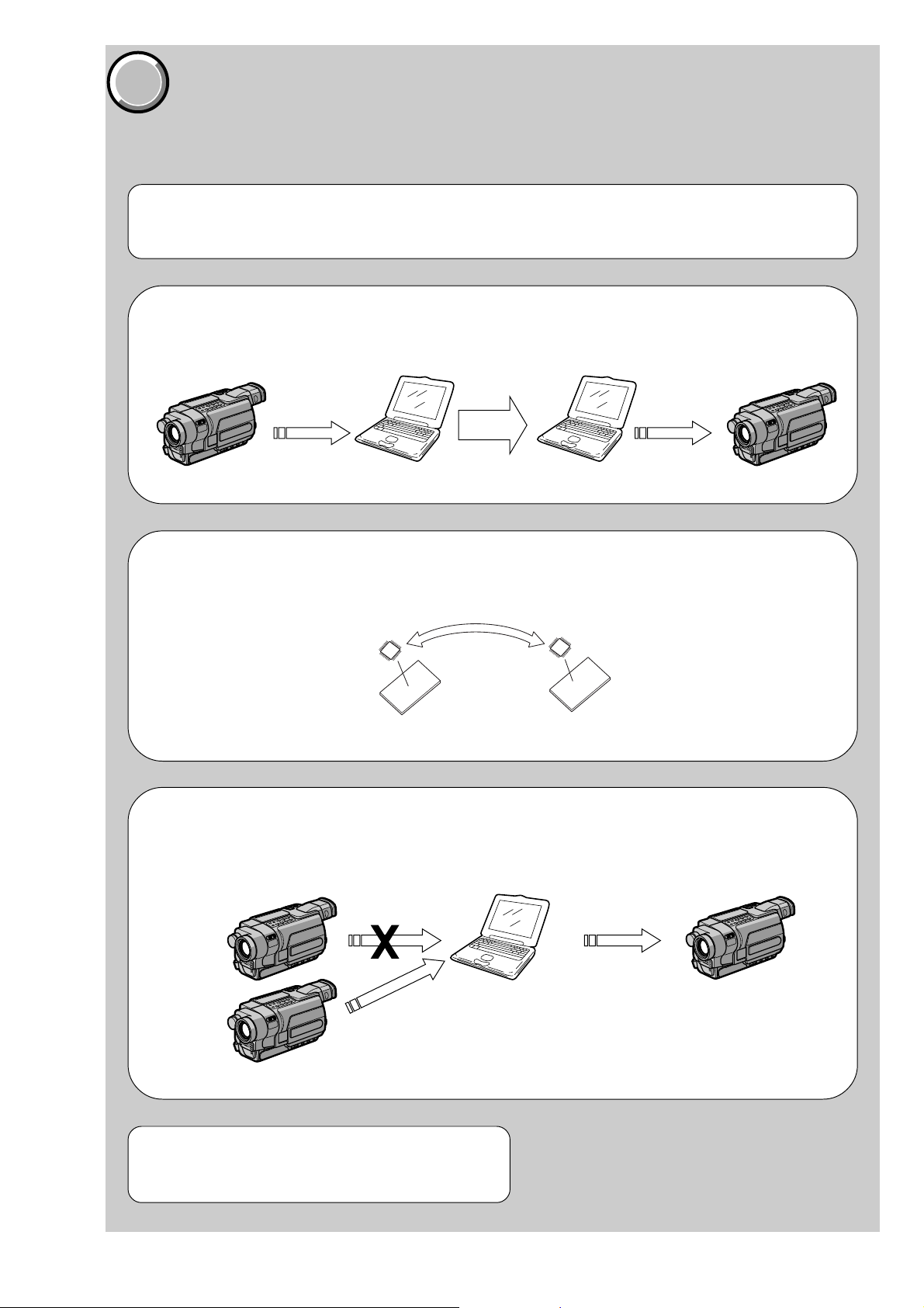
1. Before starting adjustments
EVR Data Re-writing Procedure When Replacing Board
The data that is stored in the repair board, is not necessarily correct.
Perform either procedure 1 or procedure 2 or procedure 3 when replacing board.
Procedure 1
Save the EVR data of the machine in which a board is going to be replaced. Download the saved data after a
board is replaced.
SECTION 6
ADJUSTMENTS
Procedure 2
Remove the EEPROM from the board of the machine that is going to be repaired. Install the removed
EEPROM to the replaced board.
Remove the EEPROM and install it.
(Former board)
(New board)
Procedure 3
When the data cannot be saved due to defective EEPROM, or when the EEPROM cannot be removed or
installed, save the data from the same model of the same destination, and download it.
(Machine to be repaired) (Machine to be repaired)
PC
Download the data.
After the EVR data is saved and downloaded, chec k the
respective items of the EVR data.
(Refer to page 6-3 for the items to be checked)
Save the data.
(The same model of the same destination)
6-1
DCR-TRV345E/TRV350/TRV351/TRV355E/TRV356E
COVER
COVER
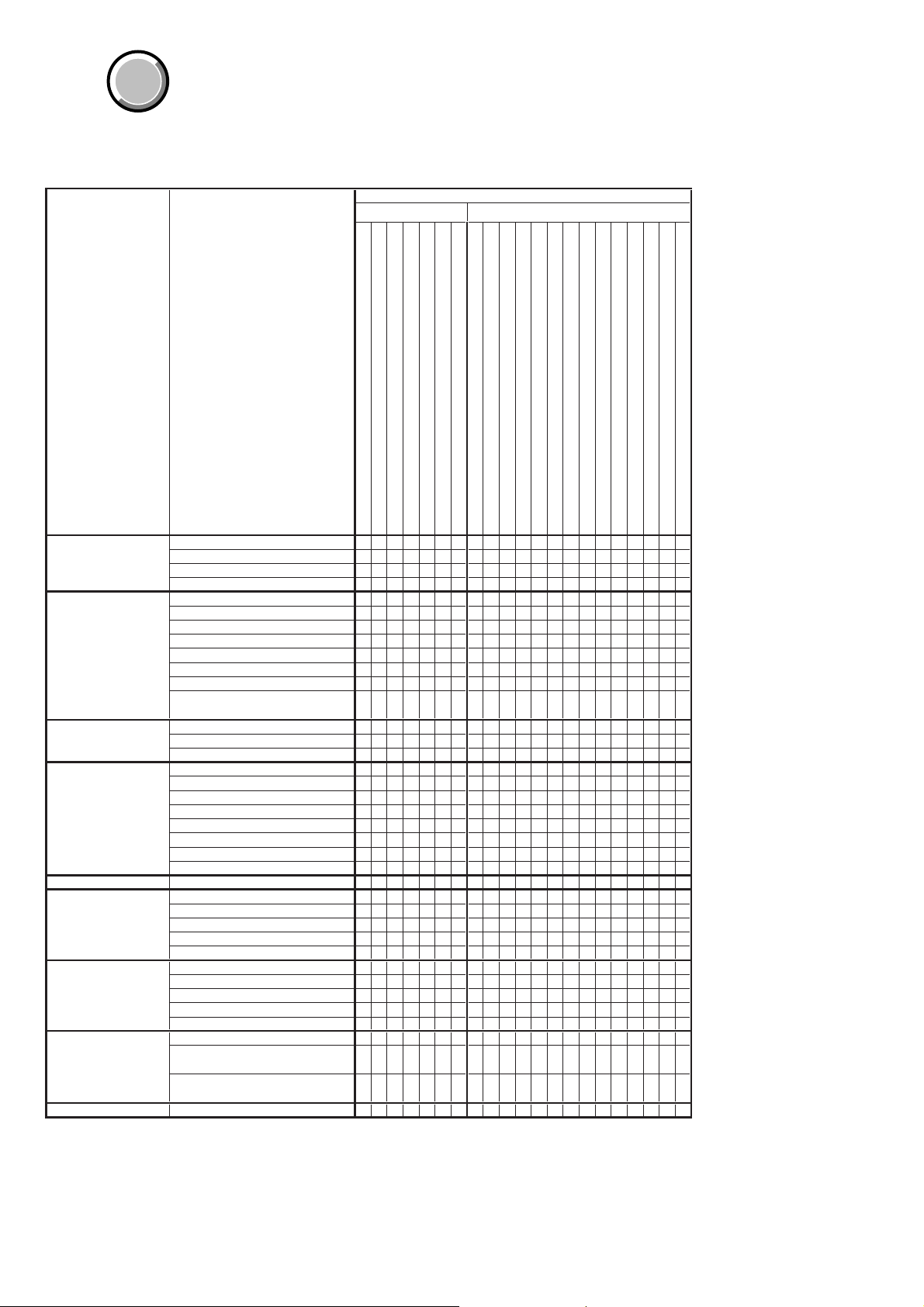
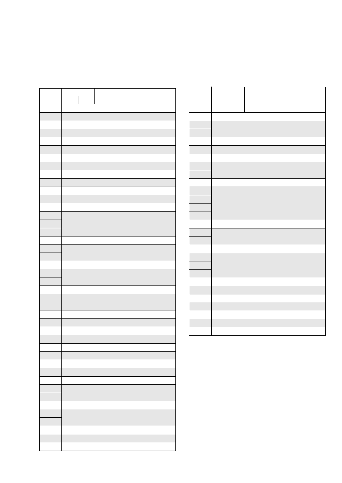
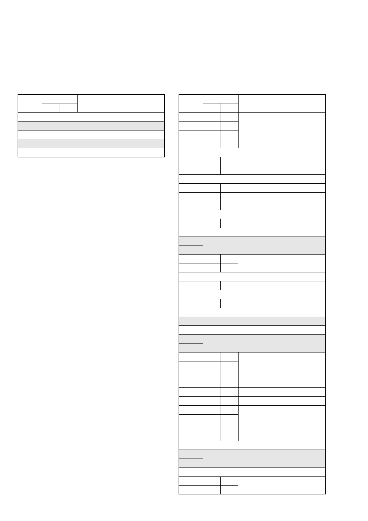
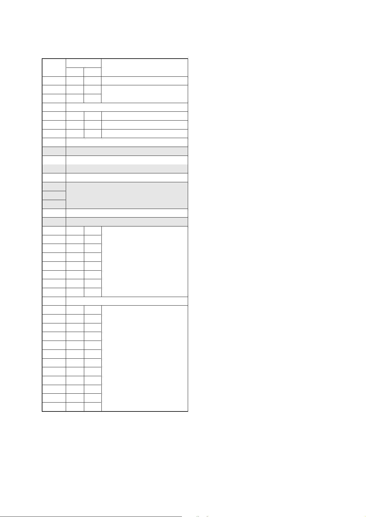
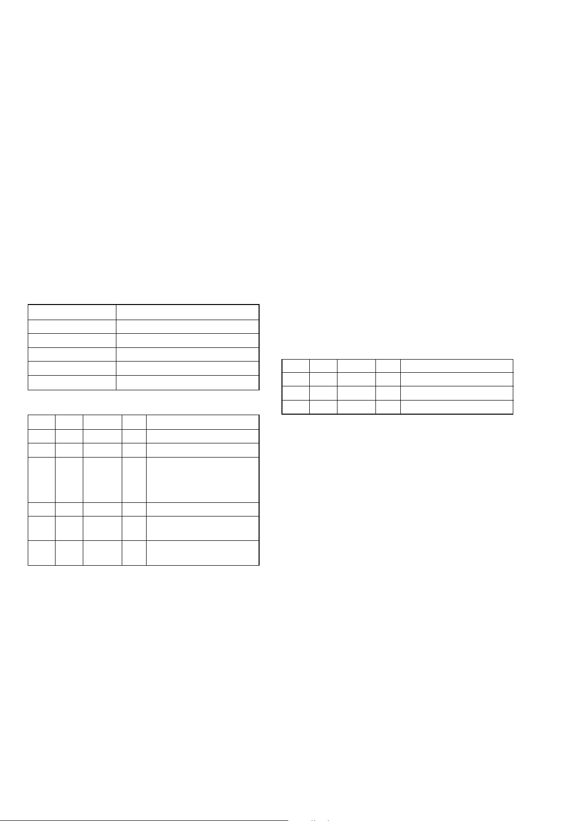
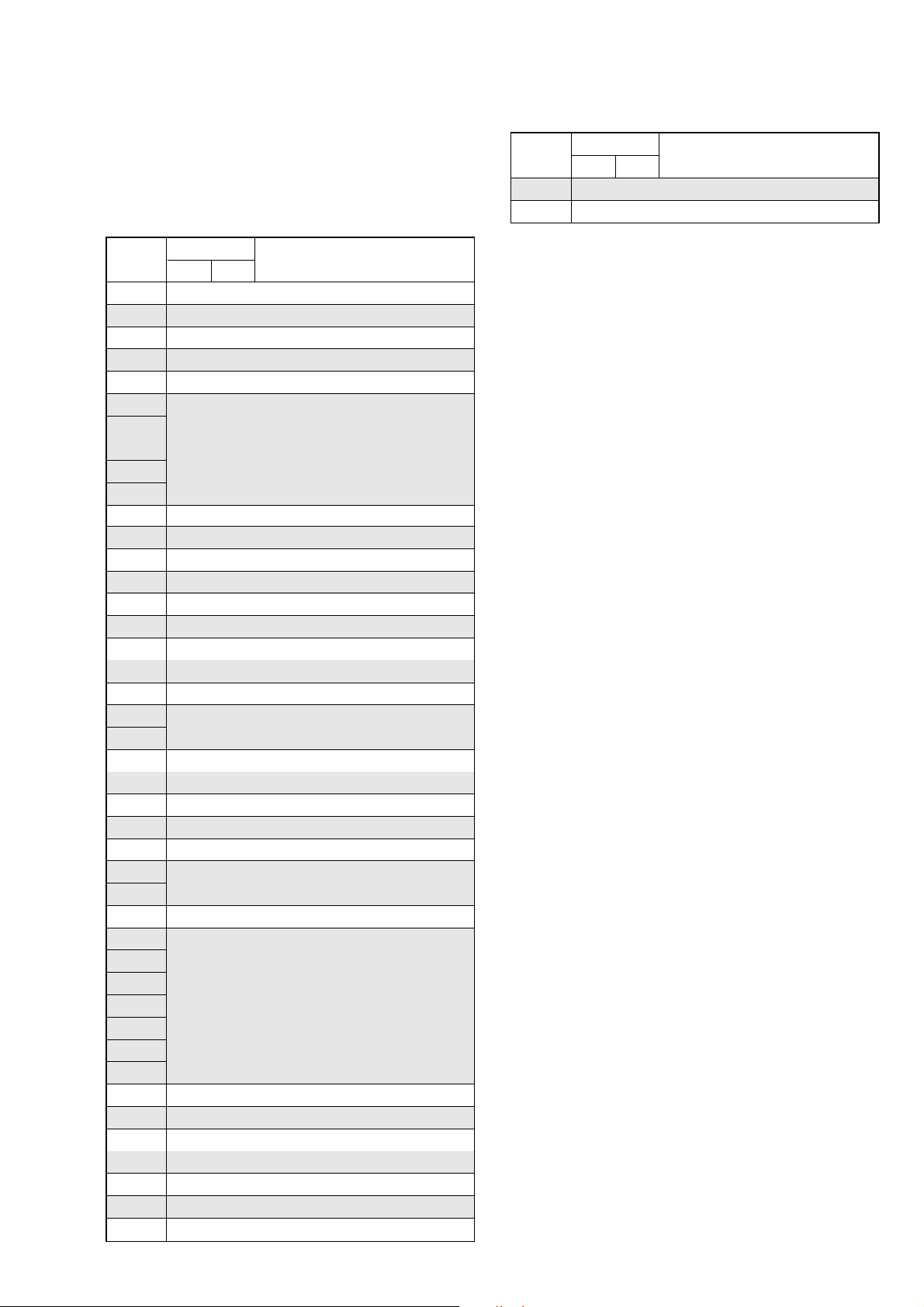
1-1. Adjusting items when replacing main parts and boards
• Adjusting items when replacing main parts
When replacing main parts, adjust the items indicated by z in the following table.
Block replacement Mounted part replacement
Replaced part
Adjustment Section Adjustment
Initialization of 8, A, B,
C, D, E, F, 18, 1B, 1C, Initializing of B, 1B page data
1F page data Initializing of 8, C, 18, 1C page data
Camera HALL adj.
EVF VCO adj.
LCD VCO adj.
System control Node uniqe ID No. input
Servo, RF REEL FG adj.
Video 27/36 MHz origin osillation adj.
Audio Hi8/Standard8 AFM BPF f
Mechanism Tape path adj.
Initializing of A, D page data
Initializing of E, F, 1F page data
Flange back adj.
Optical axis adj.
Color reproduction adj.
LV standard data input
AWB standard data input
Auto white balance adj.
Angular velocity sensor output check
and steadyshot check
RGB AMP adj.
Contrast adj.
PSIG GRAY adj.
RGB AMP adj.
Black limit adj.
Contrast adj.
Center voltage adj.
V-COM adj.
White balance adj.
CAP FG duty adj.
Digital8 switching position adj.
SD error rate check (LP)
Hi8/Standard8 switching position adj.
S VIDEO OUT Y level adj.
S VIDEO OUT C level adj.
Hi8/Standard8 Y/C output level setting
Hi8/Standard8 AFC f
Hi8/Standard8 AFM 1.5 MHz
deviation adj.
Hi8/Standard8 AFM 1.7 MHz
deviation adj.
0
adj.
0
adj.
Table 6-1-1 (1)
(LCD panel)
(Fluorescent tube)
(Drum assembly) (Note 1)
(Capstan motor)
(CCD imager)
(YAW, PITCH sensor)
(Timing generator)
(S/H, AGC, A/D CONV.)
(Video/audio DSP)
(Hi8/Standard8 VTR process)
(DV signal process)
(Video in/out)
(EVR)
(Audio process)
(LCD drive)
(Timing generator)
(LCD drive)
(Timing generator)
Lens device
Video light (Note 2)
LCD block LCD901
LCD block ND901
Mechanism deck (Note 1)
Mechanism deck M901
Mechanism deck M902
CD-418 board IC951
SI-036 board SE751/752
VC-305 board IC1501, X1501
VC-305 board IC1502
VC-305 board IC8001
VC-305 board IC2201
VC-305 board IC6001
VC-305 board IC3701
VC-305 board IC1601
VC-305 board IC5401
VC-305 board IC7001
VC-305 board IC7002
PD-181 board IC5501
PD-181 board IC5502
z
zz
zz
zz
zz z
z
zz
zz
zz z
zz
zzz
zz
zz
zz
zz
z
zz
z
z
zz
z
z
z
z
z
zz
zz
zz
z
z
z
z
z
Note 1: When replacing the drum assy or mechanism deck, reset the data of page: 7, address: A7 to A9.
(Refer to “Record of Use Check” of “6-4. SERVICE MODE”)
Note 2: When replacing the video light, reset the data of page: 7, address: CE and CF.
(Refer to “Record of Use Check” of “6-4. SERVICE MODE”)
6-2
DCR-TRV345E/TRV350/TRV351/TRV355E/TRV356E
RadarW
RadarW
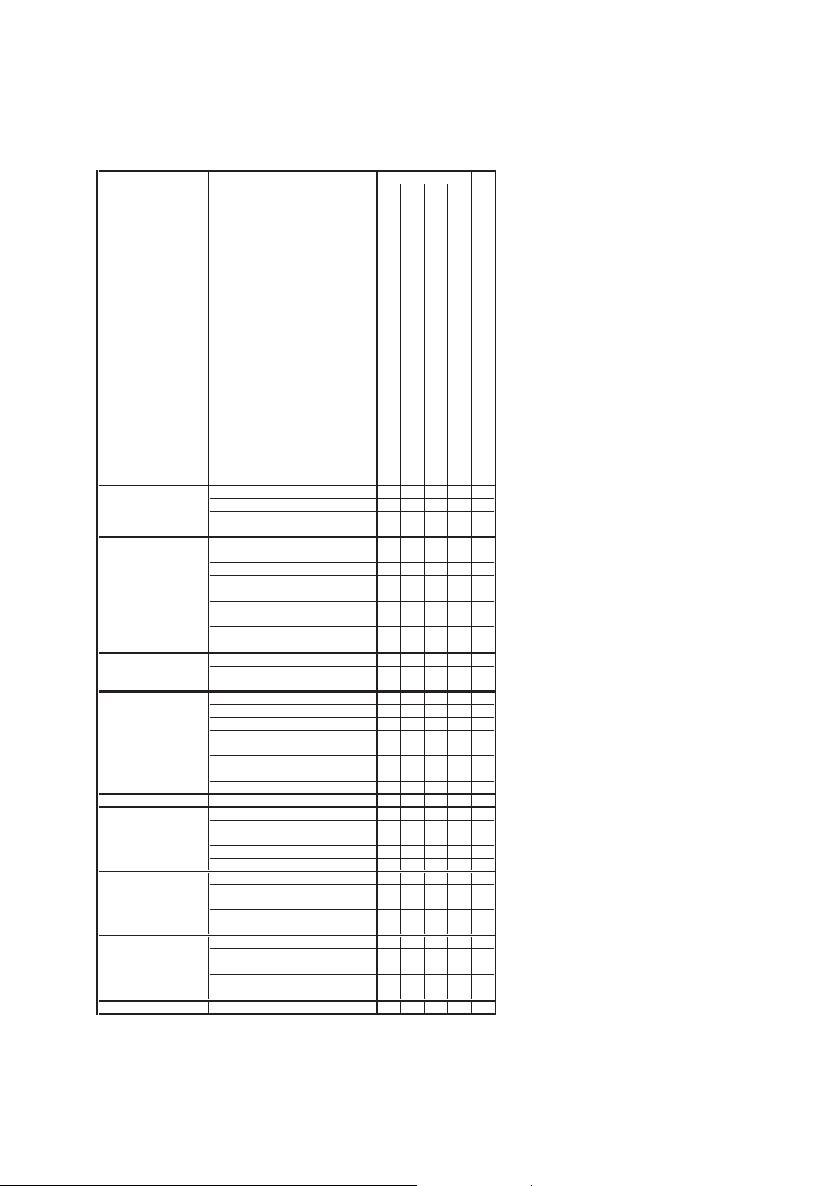
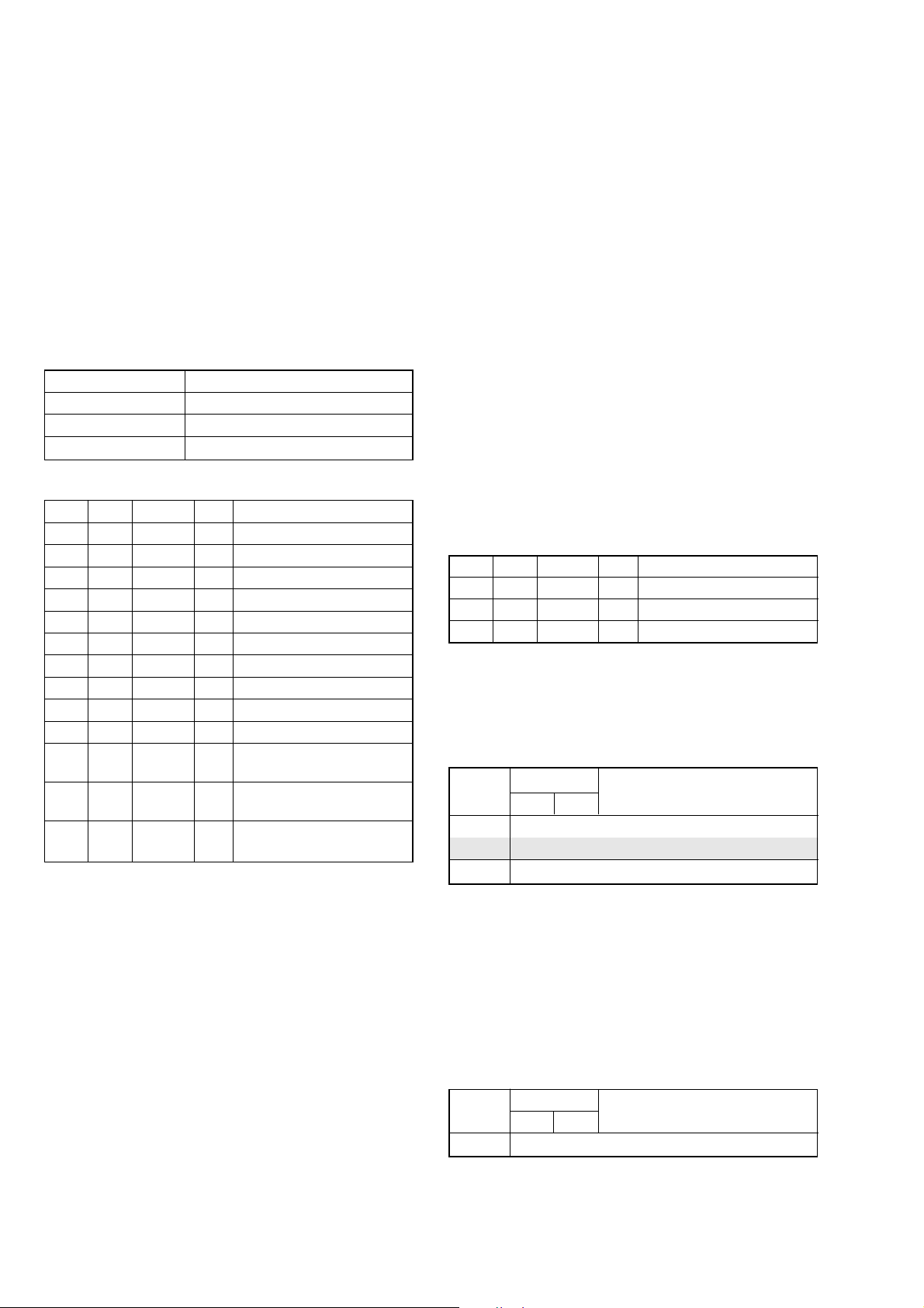
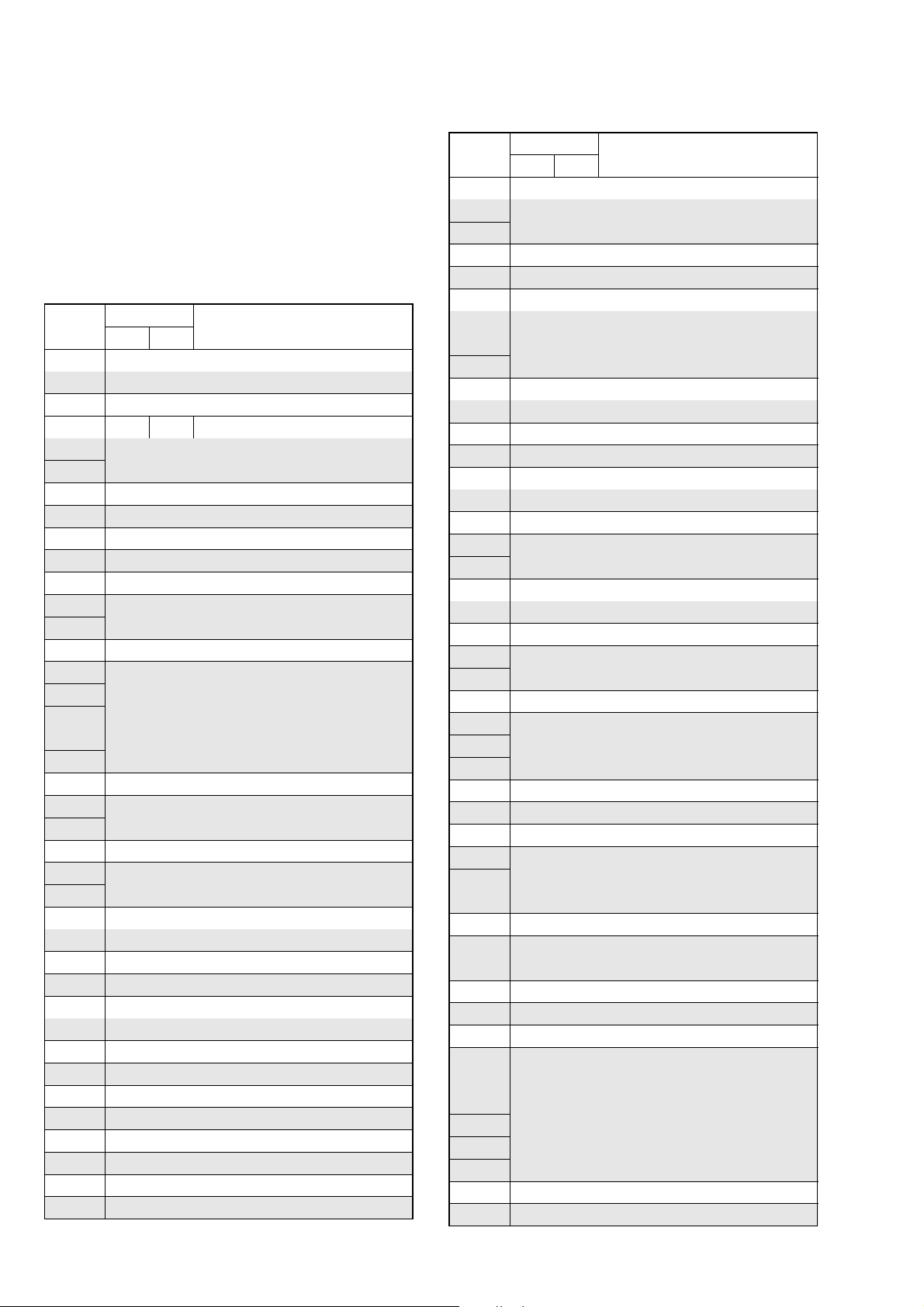
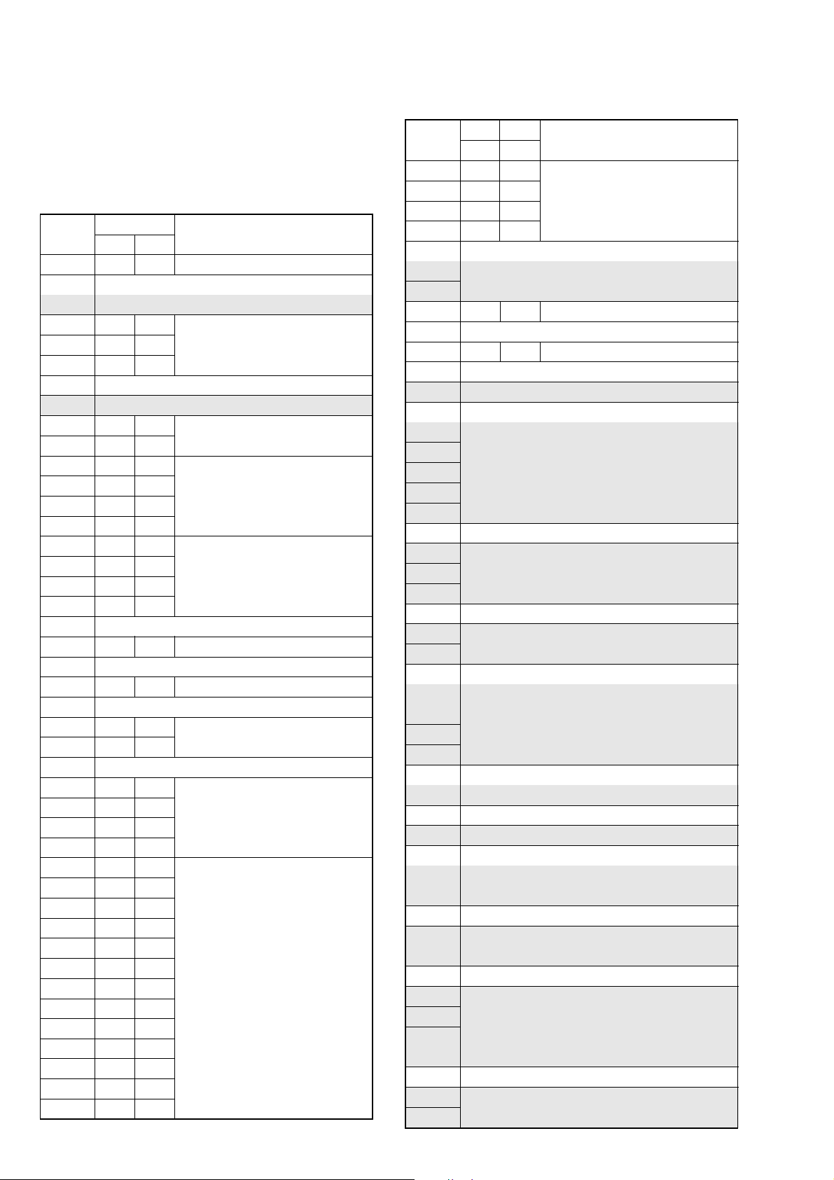
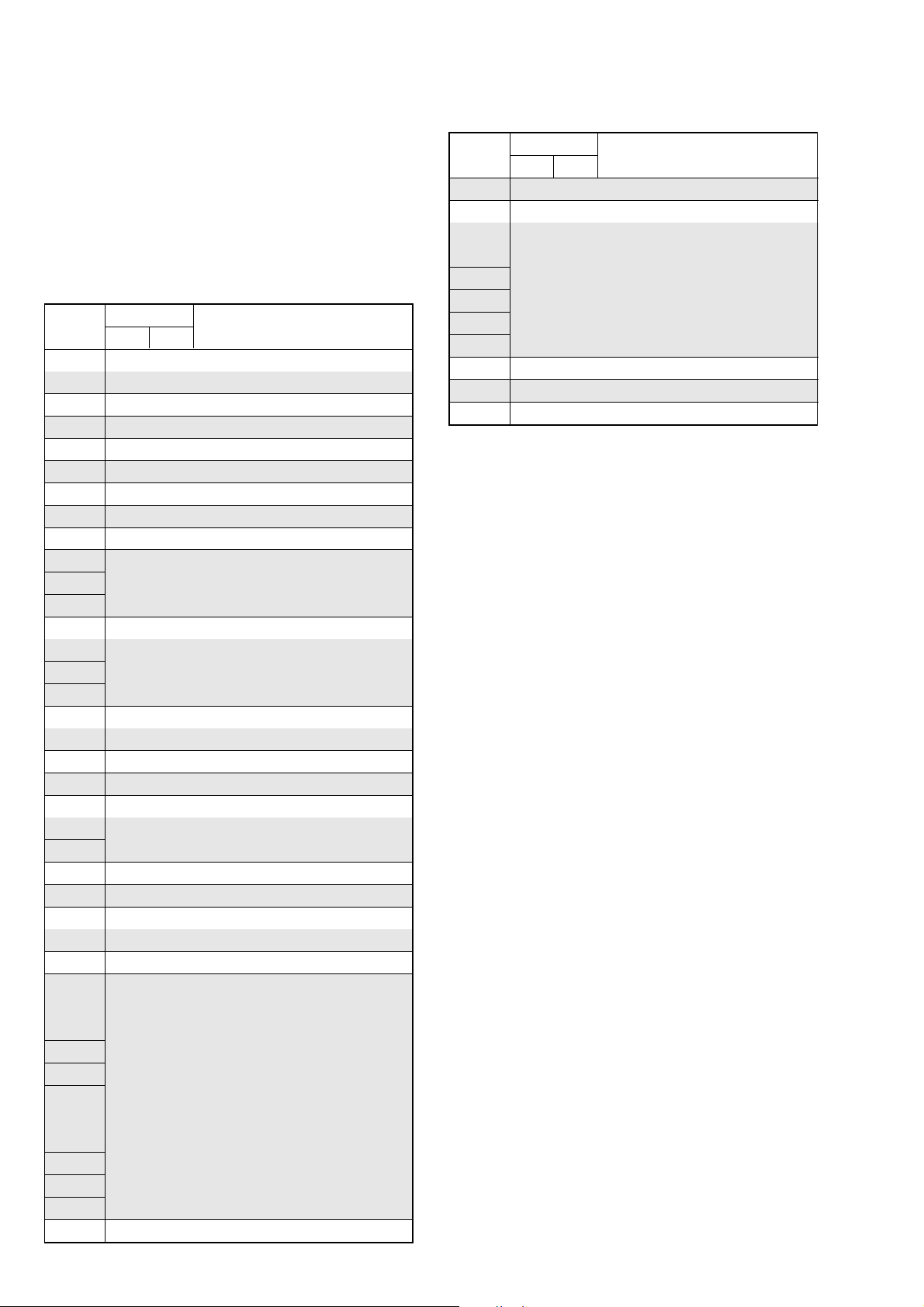
• Adjusting items when replacing a board or EEPROM
When replacing a board or EEPROM, adjust the items indicated by z in the following table.
Replaced part
Adjustment Section Adjustment
Initialization of 8, A, B,
C, D, E, F, 18, 1B, 1C, Initializing of B, 1B page data
1F page data Initializing of 8, C, 18, 1C page data
Camera HALL adj.
EVF VCO adj.
LCD VCO adj.
System control Node uniqe ID No. input
Servo, RF REEL FG adj.
Video 27/36 MHz origin osillation adj.
Audio Hi8/Standard8 AFM BPF f
Mechanism Tape path adj.
Initializing of A, D page data
Initializing of E, F, 1F page data
Flange back adj.
Optical axis adj.
Color reproduction adj.
LV standard data input
AWB standard data input
Auto white balance adj.
Angular velocity sensor output check
and steadyshot check
RGB AMP adj.
Contrast adj.
PSIG GRAY adj.
RGB AMP adj.
Black limit adj.
Contrast adj.
Center voltage adj.
V-COM adj.
White balance adj.
CAP FG duty adj.
Digital8 switching position adj.
SD error rate check (LP)
Hi8/Standard8 switching position adj.
S VIDEO OUT Y level adj.
S VIDEO OUT C level adj.
Hi8/Standard8 Y/C output level setting
Hi8/Standard8 AFC f
Hi8/Standard8 AFM 1.5 MHz
deviation adj.
Hi8/Standard8 AFM 1.7 MHz
deviation adj.
0
adj.
0
adj.
Table 6-1-1 (2)
(COMPLETE)
(COMPLETE)
(EEP ROM)
(EEP ROM)
PD-181 board
VC-305 board
VC-305 board IC4405
zz
zz
zz
zz
zzz
zzz
zz
zz
zzz
zzz
zzz
zzz
zz
zzz
zzz
zz z
zz z
zz z
zz z
zz z
zz z
zz z
zz z
zz
zzz
zzz
zzz
zzz
zz
zz
zz
zz
zzz
zzz
zz
zz
zz
VC-305 board IC4502
RadarW
RadarW
RadarW
Supporting
6-3
DCR-TRV345E/TRV350/TRV351/TRV355E/TRV356E
COVER
COVER
6-1. CAMERA SECTION ADJUSTMENTS
1-1. PREPARATIONS BEFORE ADJUSTMENTS (CAMERA SECTION)
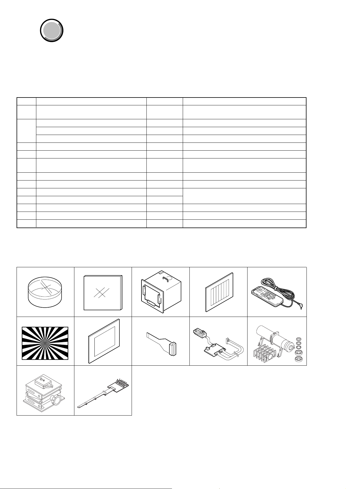
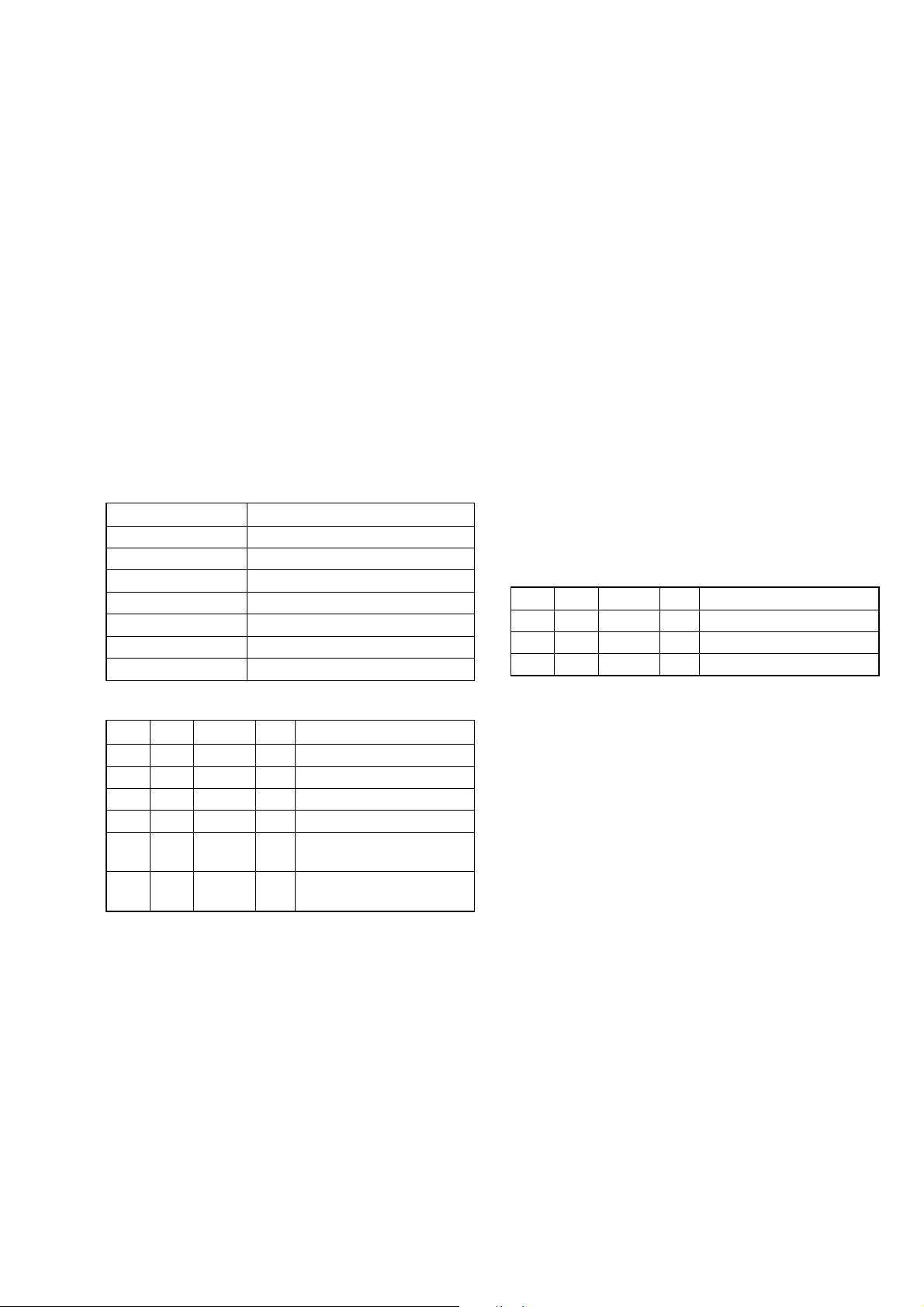
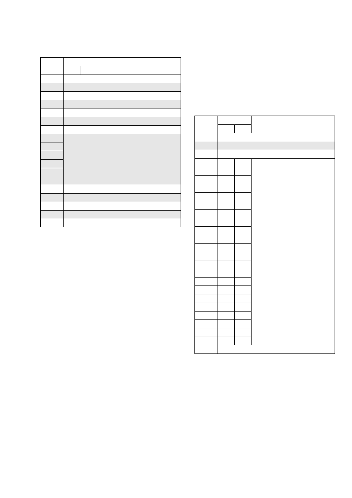
1-1-1. List of Ser vice Tools
• Oscilloscope • Color monitor • Vectorscope
• Regulated power supply • Digital voltmeter • Frequency counter
Ref. No.
J-1
J-2
J-3
J-4
J-5
J-6
J-7
J-8
J-9
J-10
J-11
J-12
Filter for color temperature correction (C14)
ND filter 1.0
ND filter 0.4
ND filter 0.1
Pattern box PTB-450
Color chart for pattern box
Adjustment remote commander (RM-95 upgraded).
(Note)
Siemens star chart
Clear chart for pattern box
CPC jig connector
I/F unit for LANC control
Mini pattern box
Camera table
Multi CPC jig
Name
Parts Code
J-6080-058-A
J-6080-808-A
J-6080-806-A
J-6080-807-A
J-6082-200-A
J-6020-250-A
J-6082-053-B
J-6080-875-A
J-6080-621-A
J-6082-539-A
J-6082-521-A
J-6082-353-B
J-6082-384-A
J-6082-311-A
Auto white balance adjustment/check
White balance adjustment/check
White balance check
White balance check
White balance check
For checking the flange back
For adjusting the electronic viewfinder system
For adjusting the video section
For adjusting the flange back
For adjusting the flange back
For adjusting the LCD system
Usage
Note: If the micro processor IC in the adjustment remote com-
mander is not the new micro processor (UPD7503G-C56-
12), the pages cannot be switched. In this case, replace with
the new micro processor (8-759-148-35).
J-1 J-2
J-6
J-11
J-7 J-8
J-12
J-3
J-4 J-5
J-9 J-10
Fig. 6-1-1
6-4
1-1-2. Preparations
DCR-TRV345E/TRV350/TRV351/TRV355E/TRV356E
Note 1: For details of how remove the cabinet and boards, refer
to “2. DISASSEMBLY”.
Note 2: When performing only the adjustments, the lens block
and boards need not be disassembled.
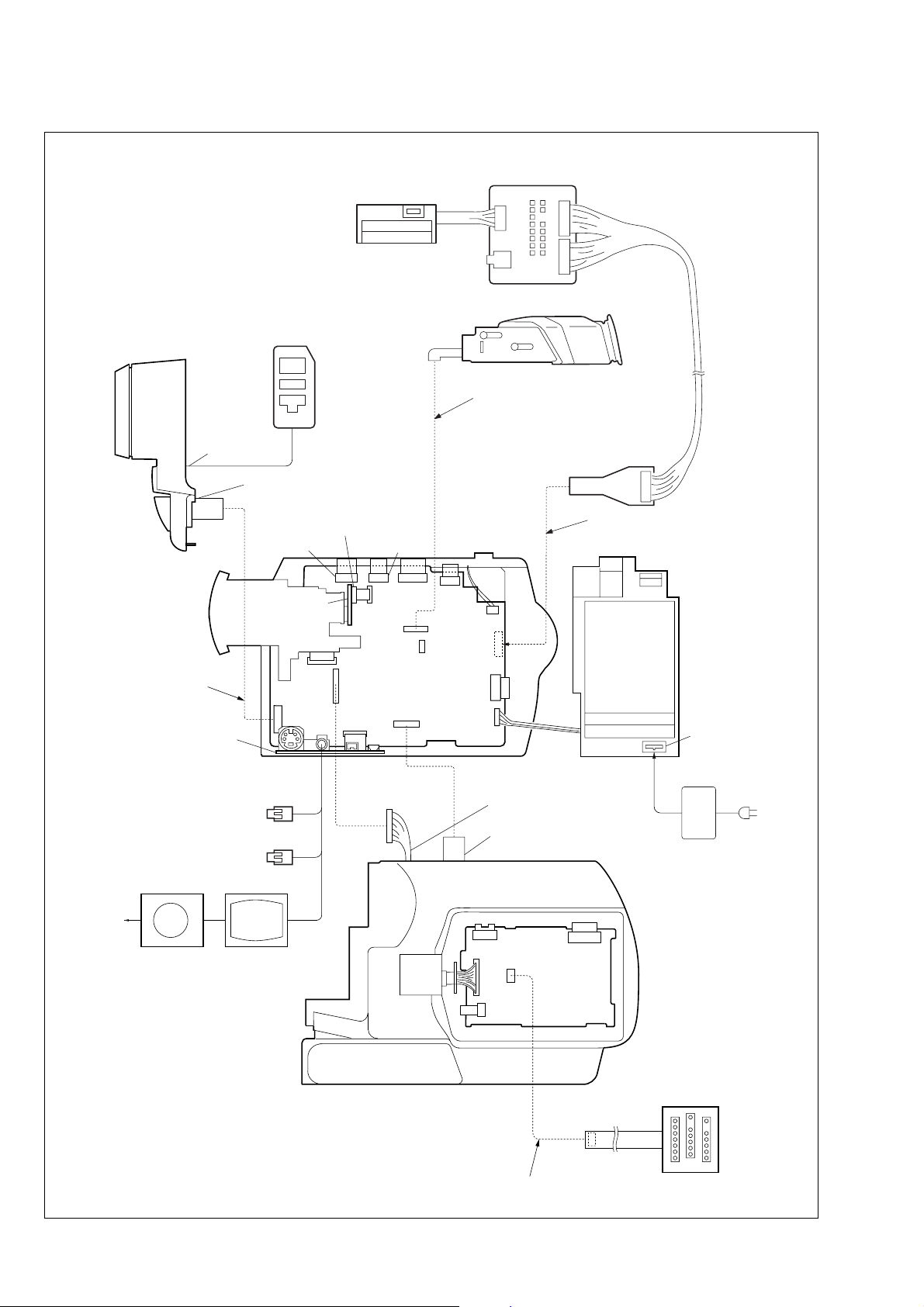
1) Connect the equipment for adjustments according to Fig. 6-1-
3.
Note 3: As removing the cabinet (R) (removing the VC-305 board
CN1007) means removing the lithium 3V power supply
(CF-3000 block BT001), data such as date, time, userset menus will be lost. After completing adjustments,
reset these data. If the cabinet (R) has been removed, the
self-diagnosis data, data on history of use (total drum
rotation time, etc. ) will be lost. Before removing, note
down the self-diagnosis data (data of page: 7, address:
B0 to C6) and data on history use (data of page: 7, address: A7 to A9 and C8 to CF). (Refer to “SELF-DIAGNOSIS FUNCTION” for the self-diagnosis data, and to
“6-4. Service Mode” for the data on the history use)
Note 4: Setting the “Forced Camera Power ON” Mode
1) Select page: 0, address: 01, and set data: 01.
2) Select page: D, address: 10, set data: 01, and press
the PAUSE button of the adjustment remote commander.
The above procedure will enable the camera power
to be turned on with the power switch (SS-3000 block)
removed. After completing adjustments, be sure to
exit the “Forced Camera Power ON Mode”.
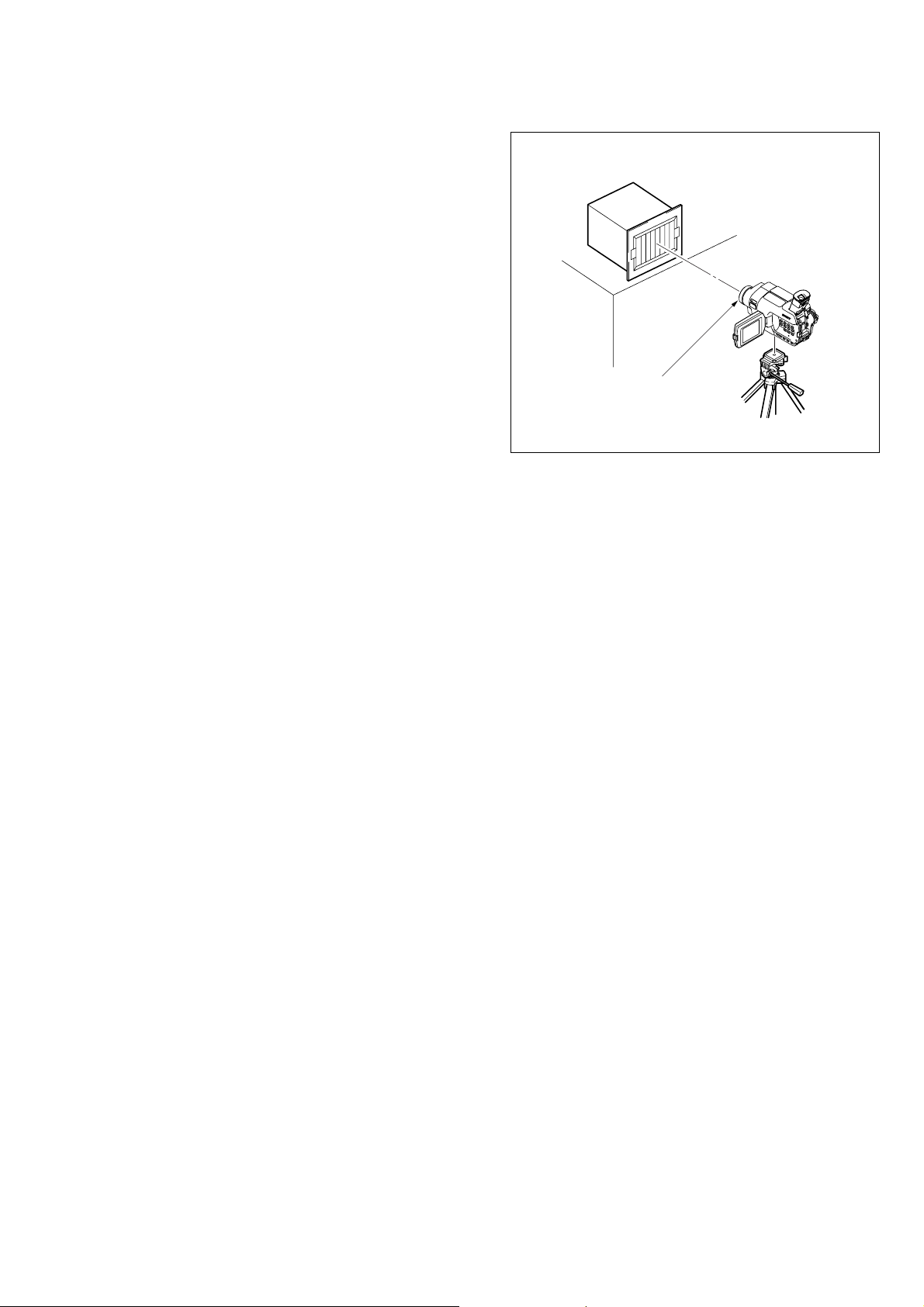
Pattern box
1.5 m
Front of the lens
Fig. 6-1-2
Note 5: Exiting the “Forced Camera Power ON” Mode
1) Select page: 0, address: 01, and set data: 01.
2) Select page: D, address: 10, set data: 00, and press
the PAUSE button of the adjustment remote commander.
3) Select page: 0, address: 01, and set data: 00.
6-5
DCR-TRV345E/TRV350/TRV351/TRV355E/TRV356E
I/F unit for LANC control
(J-6082-521-A)
Adjustment
remote commander
FRONT PANEL BLOCK
Must be connected
when performing
the EVF sytem adjustment.
To LANC jack
To SI-036 board CN753
EVF BLOCK
CPC jig connector
(J-6082-539-A)
Must be connected
Terminated
75 Ω
FP-577 flexible
Color monitorVector scope
CN2404
CD-418 board
LENS BLOCK
CN1551
CN1002
Audio R (red)
Audio L (white)
Video
(yellow)
CN951
CN1003
CN1001
CN3201
CN2403
CN1005
CN1501
CN1013
VC-305 board
CN1007
CN2402
CN2401
CN1011
CN1009
CN4001
To PD-181 board CN5701
To CONTROL
SWITCH BLOCK (CF-3000)
CN5601
CN5502
CN5501
Must be connected when
performing the EVF sytem
or video section adjustment.
DC IN jack
AC power adaptor
CABINET (R)
Fig. 6-1-3
6-6
CN5701
CN5702
PD-181
board
Must be connected when performing
the LCD sytem adjustment.
Multi CPC jig
(J-6082-311-A)
DCR-TRV345E/TRV350/TRV351/TRV355E/TRV356E
1-1-3. Precaution
1. Setting the Switch
Unless otherwise specified, set the switches as follows and perform adjustments without loading cassette.
1. POWER switch (SS-3000 block) ..........................CAMERA
2. FOCUS (CF-3000 block) ..................................... MANUAL
3. BACK LIGHT (CF-3000 block) .................................... OFF
4. PROGRAM AE (MENU setting) ................................... OFF
5. NIGHT SHOT switch (Lens block) ............................... OFF
6. EXPOSURE (CF-3000 block) .................................... AUTO
2. Order of Adjustments
Basically carry out adjustments in the order given.
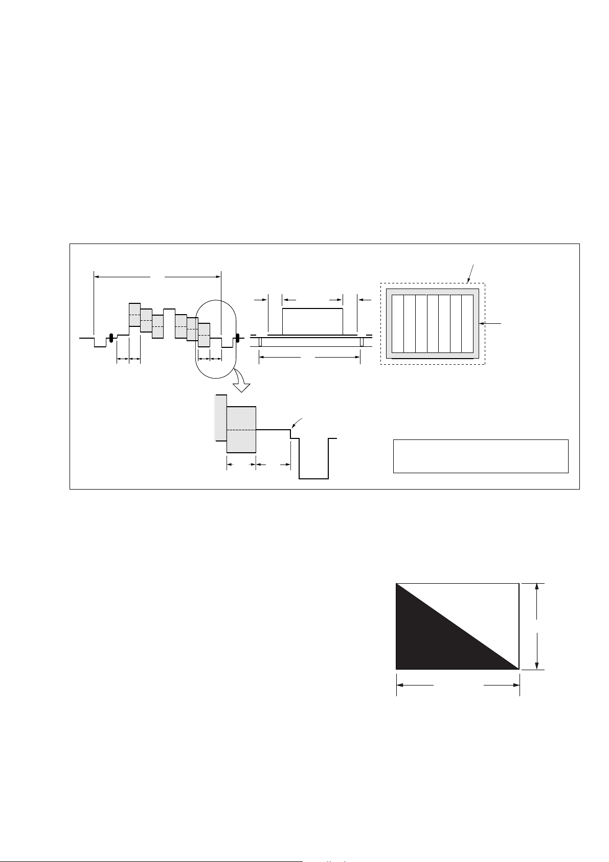
Color bar chart (Color reproduction adjustment frame)
H
Yellow
Cyan
Green
AB B
Fig. a
(VIDEO terminal of A/V jack
output waveform)
A=B
White
Magenta
Red
CD
Blue
A
Enlargement
C=D
Difference in level
7. P EFFECT (MENU setting) ........................................... OFF
8. DEFFECT (MENU setting) ........................................... OFF
9. D ZOOM (MENU setting) ............................................. OFF
10. DEMO MODE (MENU setting) .................................... OFF
11. 16 : 9 WIDE (MENU setting) ........................................ OFF
Electronic beam scanning frame
Red
Cyan
White
Green
Yellow
V
Fig. b (monitor TV picture)
Blue
Magenta
CRT picture frame
B
A
Fig. 6-1-4
3. Subjects
1) Color bar chart (Color reproduction adjustment frame)
When performing adjustments using the color bar chart, adjust
the picture frame as shown in Fig. 6-1-4. (Color reproduction
adjustment frame)
2) Clear chart (Color reproduction adjustment frame)
Remove the color bar chart from the pattern box and insert a
clear chart in its place. (Do not perform zoom operations during
this time)
3) Chart for flange back adjustment
Join together a piece of white A0 size paper (1189mm × 841
mm) and a piece of black paper to make the chart shown in
Fig. 6-1-5.
Note: Use a non-reflecting and non-glazing vellum paper. The
size must be A0 or larger and the joint between the white
and black paper must not have any undulations.
Adjust the camera zoom and direction to
obtain the output wavef orm shown in Fig. a and
the monitor TV display shown in Fig. b.
White
841 mm
Black
1189 mm
Fig. 6-1-5
6-7
DCR-TRV345E/TRV350/TRV351/TRV355E/TRV356E
COVER
COVER
1-2. INITIALIZATION OF 8, A, B, C, D , E, F, 18,
1B, 1C, 1F PAGE DATA
Note: If reading/writing data on pages 18, 1B, 1C, 1F, set data:
01 to page: 0, address: 10, and then select pages 8, B, C, F .
By this data setting, the pages 18, 1B, 1C, 1F can be selected.
After the data reading/writing finished, return the data on
page: 0, address: 10 to “00”.
1-2-1. Initialization of A, D Page Data
Note: Check that the data of page: 0, address: 10 is “00”.
1. Initializing the A, D Page Data
Note 1: If “Initialization of Pages A, D” is executed, all data on
pages A, D are initialized. (Only an indi vidual page cannot be initialized)
Note 2: If the A, D page data has been initialized, the following
adjustments need to be performed again.
1) Modification of A, D page data
Note 3: NTSC model: DCR-TRV350/TRV351
PAL model: DCR-TRV345E/TRV355E/TRV356E
Adjustment Page A
Adjustment Address 10 to FF
Adjustment Page D
Adjustment Address 10 to FF
Initializing method:
Order Page Address Data Procedure
10 0101
20 1000
Set the following data
37 03
47 0028
57 01 28 Press PAUSE button.
67 02
7
01: NTSC model
81: PAL model
Check the data changes to
“01”.
Perform “Modification of A,
D Page Data”
2. Modification of A, D Page Data
If the A, D page data has been initialized, change the data of
the“Fixed data-2” address shown in the follo wing table by manual
input.
Modifying Method:
1) Before changing the data, select page: 0, address: 01, and set
data: 01.
2) New data for changing are not shown in the tables because
they are different in destination. When changing the data, cop y
the data built in the same model.
Note 1: If copy the data built in the different model, the
camcorder may not operate.
3) When changing the data, press the PAUSE button of the adjustment remote commander each time when setting new data
to write the data in the non-volatile memory.
4) Check that the data of adjustment addresses is the initial value.
If not, change the data to the initial value.
Processing after Completing Modification A, D page data:
Order Page Address Data Procedure
12 0029
22 01 29 Press PAUSE button.
Note 2: If the following symptoms occur after completing of
the“Modification A, D pa ge data”, check that the data of
the “Fixed data-2” addresses of A, D page are same as
those of the same model of the same destination.
1) The power is shut off so that unit cannot operate.
6-8
DCR-TRV345E/TRV350/TRV351/TRV355E/TRV356E
3. A Page table
Note 1: Check that the data of page: 0, address: 10 is “00”.
Note 2: Fixed data-1: Initialized data. (Refer to “1. Initializing
the A, D Page Data”)
Fixed data-2: Modified data. (Refer to “2. Modification
of A, D Page Data”)
Address
10 to 17 Fixed data-1 (Initialized data)
19, 1A Fixed data-1 (Initialized data)
1B Fixed data-2
1C to 2C Fixed data-1 (Initialized data)
2D Fixed data-2
2E, 2F Fixed data-1 (Initialized data)
31 to 35 Fixed data-1 (Initialized data)
37 to 39 Fixed data-1 (Initialized data)
3A Fixed data-2
3B Fixed data-1 (Initialized data)
3C
3D Fixed data-2
3E
3F to 4F Fixed data-1 (Initialized data)
52 to 54 Fixed data-1 (Initialized data)
57 to 5A Fixed data-1 (Initialized data)
5B
5C
5D, 5E Fixed data-1 (Initialized data)
60 to 62 Fixed data-1 (Initialized data)
64 to 66 Fixed data-1 (Initialized data)
68 to 6C Fixed data-1 (Initialized data)
6D Fixed data-2
6E to A3 Fixed data-1 (Initialized data)
A4
A5
A6 to A9 Fixed data-1 (Initialized data)
AA
AB
AC to B3 Fixed data-1 (Initialized data)
B4 Fixed data-2
B5 to FF Fixed data-1 (Initialized data)
Initial value
NTSC PAL
18 Fixed data-2
30 Fixed data-2
36 Fixed data-2
50
51
55
56
5F Fixed data-2
63 Fixed data-2
67 Fixed data-2
Fixed data-2
Fixed data-2
Fixed data-2
Fixed data-2
Fixed data-2
Remark
4. D Page table
Note 1: Check that the data of page: 0, address: 10 is “00”.
Note 2: Fixed data-1: Initialized data. (Refer to “1. Initializing
the A, D Page Data”)
Fixed data-2: Modified data. (Refer to “2. Modification
of A, D Page Data”)
Address
14, 15 Fixed data-1 (Initialized data)
17 to 19 Fixed data-1 (Initialized data)
1A
1B
1C to 22 Fixed data-1 (Initialized data)
27 to 29 Fixed data-1 (Initialized data)
2A
2B
2C to 35 Fixed data-1 (Initialized data)
3A Fixed data-2
3B to 58 Fixed data-1 (Initialized data)
5A to 6E Fixed data-1 (Initialized data)
70 to FF Fixed data-1 (Initialized data)
Initial value
NTSC PAL
10 00 00 Test mode
11 Fixed data-1 (Initialized data)
12
13
16 Fixed data-2
23
24
25
26
36
37 Fixed data-2
38
39 Fixed data-1 (Initialized data)
59 Fixed data-2
6F Fixed data-2
Fixed data-2
Fixed data-2
Fixed data-2
Fixed data-2
Remark
6-9
DCR-TRV345E/TRV350/TRV351/TRV355E/TRV356E
1-2-2. Initialization of B, 1B Page Data
Note: If reading/writing data on pages 1B, set data: 01 to page:
0, address: 10, and then select pages B. By this data setting, the pages 1B can be selected.
After the data reading/writing finished, return the data on
page: 0, address: 10 to “00”.
1. Initializing the B, 1B Page Data
Note 1: If “Initialization of Pages B, 1B” is executed, all data on
pages B, 1B are initialized. (Only an individual page cannot be initialized)
Note 2: If the B, 1B page data has been initialized, the following
adjustments need to be performed again.
1) Modification of B, 1B page data
Adjustment Page B
Adjustment Address 00 to FF
Adjustment Page 1B
Adjustment Address 00 to FF
Initializing method:
Order Page Address Data Procedure
10 0101
20 1000
35 02FF
45 01 F3 Press PAUSE button.
55 00 01 Press PAUSE button.
65 02 Check the data changes to “00”.
75 0E 00 Press PAUSE button.
85 03 20 Press PAUSE button.
95 01 FA Press PAUSE button.
10 5 00 01 Press PAUSE button.
11 5 0E
12
13
Check the data changes to
“01”.
Turn off the power supply,
then turn on them again.
Perform “Modification of B
Page Data”
2. Modification of B, 1B Page Data
If the B, 1B page data has been initialized, change the data of the
“Fixed data-2” address shown in the following table by manual
input.
Modifying Method:
1) Before changing the data, select page: 0, address: 01, and set
data: 01.
2) If modification of data on pages B, set data: 00 to page: 0,
address: 10, and then select pages B.
3) If modification of data on pages 1B, set data: 01 to page: 0,
address: 10, and then select pages B. After the modif ication of
data finished, return the data on page: 0, address: 10 to “00”.
4) New data for changing are not shown in the tables because
they are different in destination. When changing the data, cop y
the data built in the same model.
Note: If copy the data built in the different model, the
camcorder may not operate.
5) When changing the data, press the PAUSE button of the adjustment remote commander each time when setting new data
to write the data in the non-volatile memory.
6) Check that the data of adjustment addresses is the initial value.
If not, change the data to the initial value.
Processing after Completing Modification B, 1B page data:
Order Page Address Data Procedure
10 1000
22 0029
32 01 29 Press PAUSE button.
3. B Page table
Note 1: Check that the data of page: 0, address: 10 is “00”.
Note 2: Fixed data-1: Initialized data. (Refer to “1. Initializing
the B, 1B Page Data”)
Fixed data-2: Modified data. (Refer to “2. Modification
of B, 1B Page Data”)
Address
00 to 02 Fixed data-1 (Initialized data)
04 to FF Fixed data-1 (Initialized data)
Initial value
NTSC PAL
03 Fixed data-2
Remark
4. 1B Page table
Note 1: If reading/writing data on pages 1B, set data: 01 to page:
0, address: 10, and then select pages B. By this data setting, the pages 1B can be selected.
After the data reading/writing finished, return the data
on page: 0, address: 10 to “00”.
Note 2: Fixed data-1: Initialized data. (Refer to “1. Initializing
the B, 1B Page Data”)
Fixed data-2: Modified data. (Refer to “2. Modification
of B, 1B Page Data”)
Address
00 to FF Fixed data-1 (Initialized data)
Initial value
NTSC PAL
Remark
6-10
DCR-TRV345E/TRV350/TRV351/TRV355E/TRV356E
1-2-3. Initialization of 8, C, 18, 1C Page Data
Note: If reading/writing data on pages 18, 1C, set data: 01 to
page: 0, address: 10, and then select pages 8, C. By this
data setting, the pages 18, 1C can be selected.
After the data reading/writing finished, return the data on
page: 0, address: 10 to “00”.
1. Initializing the 8, C, 18, 1C Page Data
Note 1: If “Initialization of Pages 8, C, 18, 1C” is executed, all
data on pages 8, C, 18, 1C are initialized. (Only an individual page cannot be initialized)
Note 2: If the 8, C, 18, 1C page data has been initialized, the
following adjustments need to be performed again.
1) Modification of 8, C, 18, 1C page data
2) Electronic viewfinder system adjustments
3) LCD system adjustments
4) Node unique ID No. input
5) Servo, RF system adjustments
6) “S VIDEO OUT Y level adjustment” and “S VIDEO
OUT C level adjustment” of the video system adjustments
7) Audio system adjustments
Adjustment Page 8
Adjustment Address 00 to FF
Adjustment Page C
Adjustment Address 10 to FF
Adjustment Page 18
Adjustment Address 00 to FF
Adjustment Page 1C
Adjustment Address 00 to FF
2. Modification of 8, C, 18, 1C Page Data
If the 8, C, 18, 1C page data has been initialized, change the data
of the “Fixed data-2” address shown in the following table by
manual input.
Modifying Method:
1) Before changing the data, select page: 0, address: 01, and set
data: 01.
2) If modification of data on pages 8, C, set data: 00 to page: 0,
address: 10, and then select pages 8, C.
3) If modification of data on pages 18, 1C, set data: 01 to page:
0, address: 10, and then select pages 8, C. After the modif ication of data finished, return the data on page: 0, address: 10 to
“00”.
4) New data for changing are not shown in the tables because
they are different in destination. When changing the data, cop y
the data built in the same model.
Note: If copy the data built in the different model, the
camcorder may not operate.
5) When changing the data, press the PAUSE button of the adjustment remote commander each time when setting new data
to write the data in the non-volatile memory.
6) Check that the data of adjustment addresses is the initial value.
If not, change the data to the initial value.
Processing after Completing Modification 8, C, 18, 1C page
data:
Order Page Address Data Procedure
10 1000
22 0029
32 01 29 Press PAUSE button.
Initializing method:
Order Page Address Data Procedure
10 0101
20 1000
33 8110
43 80 0C Press PAUSE button.
53 80
6
Check the data changes to
“1C”.
Perform “Modification of 8,
C, 18, 1C Page Data”
6-11
DCR-TRV345E/TRV350/TRV351/TRV355E/TRV356E
3. 8 Page table
Note 1: Check that the data of page: 0, address: 10 is “00”.
Note 2: Fixed data-1: Initialized data. (Refer to “1. Initializing
the 8, C, 18, 1C Page Data”)
Fixed data-2: Modified data. (Refer to “2. Modification
of 8, C, 18, 1C Page Data”)
Address
00 to 29 Fixed data-1 (Initialized data)
2A Fixed data-2
2B to 79 Fixed data-1 (Initialized data)
7A Fixed data-2
7B to FF Fixed data-1 (Initialized data)
Initial value
NTSC PAL
Remark
4. C Page table
Note 1: Check that the data of page: 0, address: 10 is “00”.
Note 2: Fixed data-1: Initialized data. (Refer to “1. Initializing
the 8, C, 18, 1C Page Data”)
Fixed data-2: Modified data. (Refer to “2. Modification
of 8, C, 18, 1C Page Data”)
Address
14, 15 Fixed data-1 (Initialized data)
18 to 24 Fixed data-1 (Initialized data)
28 to 2E Fixed data-1 (Initialized data)
2F 0E 0E REEL FG adj.
30 to 33 Fixed data-1 (Initialized data)
3A to 3D Fixed data-1 (Initialized data)
3E 36 36 Contrast adj. (EVF)
3F Fixed data-1 (Initialized data)
41 to 44 Fixed data-1 (Initialized data)
4A 94 94 RGB AMP adj. (LCD)
4B 04 04 Black limit adj. (LCD)
4C 42 42 PSIG GRAY adj. (LCD)
4D 77 77
4E 68 68
4F 0D 0D Contrast adj. (LCD)
51 to 60 Fixed data-1 (Initialized data)
63 to 6F Fixed data-1 (Initialized data)
Initial value
NTSC PAL
10 EE EE
11 00 00
12 00 00
13 00 00
16 E0 E0 CAP FG duty adj.
17 E0 E0 REEL FG adj.
25 80 80 S VIDEO OUT Y level adj.
26 70 70
27 50 50
34
35
36 6C 6C
37 81 81
38 Fixed data-1 (Initialized data)
39 B4 B4 RGB AMP adj. (EVF)
40 Fixed data-2
45
46
47 61 61
48 72 72
49 22 22 V-COM adj. (LCD)
50 4D 4D Center voltage adj. (LCD)
61
62
70 0A 0A
71 00 00
Digital8 switching position adj.
S VIDEO OUT C level adj.
Fixed data-2
VCO adj. (EVF)
Fixed data-2
VCO adj. (LCD)
White balance adj. (LCD)
Fixed data-2
Hi8/Standard8 switching position adj.
Remark
6-12
C Page table
Address
79 to 9B Fixed data-1 (Initialized data)
9C Fixed data-2
9D to AC Fixed data-1 (Initialized data)
AD Fixed data-2
AE to D3 Fixed data-1 (Initialized data)
D4
D5 Fixed data-2
D6
D7 to DE Fixed data-1 (Initialized data)
DF Fixed data-2
E0 08 08
E1 00 00
E2 46 46
E3 01 01
E4 02 02
E5 00 00
E6 00 00
E7 00 00
E8 to F3 Fixed data-1 (Initialized data)
FA 00 00
FB 00 00
FC 00 00
FD 00 00
FE 00 00
FF 00 00
Initial value
NTSC PAL
72 50 50 Hi8/Standard8 AFC f0 adj.
73 A0 A0
74 AA AA
75 Fixed data-1 (Initialized data)
76 A6 A6
77 94 94
78 80 80 Hi8/Standard8 AFM BPF f0 adj.
F4 00 00
F5 00 00
F6 00 00
F7 00 00
F8 00 00
F9 00 00
Hi8/Standard8 Y/C output level setting
Hi8/Standard8 AFM 1.5 MHz deviation adj.
Hi8/Standard8 AFM 1.7 MHz deviation adj.
Node unique ID No. input
Emergency memory
Remark
DCR-TRV345E/TRV350/TRV351/TRV355E/TRV356E
6-13
DCR-TRV345E/TRV350/TRV351/TRV355E/TRV356E
5. 18 Page table
Note 1: If reading/writing data on page 18, set data: 01 to page:
0, address: 10, and then select page 8. By this data setting, the page 18 can be selected.
After the data reading/writing finished, return the data
on page: 0, address: 10 to “00”.
Note 2: Fixed data-1: Initialized data. (Refer to “1. Initializing
the 8, C, 18, 1C Page Data”)
Fixed data-2: Modified data. (Refer to “2. Modification
of 8, C, 18, 1C Page Data”)
Address
00 to 0F Fixed data-1 (Initialized data)
17 to 1B Fixed data-1 (Initialized data)
1C Fixed data-2
1D, 1E Fixed data-1 (Initialized data)
2A, 2B Fixed data-1 (Initialized data)
2C
2D
2E, 2F Fixed data-1 (Initialized data)
31, 32 Fixed data-1 (Initialized data)
38 to 3A Fixed data-1 (Initialized data)
3B Fixed data-2
3C to 3E Fixed data-1 (Initialized data)
40 to 51 Fixed data-1 (Initialized data)
Initial value
NTSC PAL
10 Fixed data-2
11 Fixed data-1 (Initialized data)
12 00 00 Test mode
13
14
15 Fixed data-1 (Initialized data)
16 Fixed data-2
1F
20
21 Fixed data-1 (Initialized data)
22
23
24 Fixed data-2
25
26
27 Fixed data-1 (Initialized data)
28
29
30 Fixed data-2
33 Fixed data-2
34 Fixed data-1 (Initialized data)
35 Fixed data-2
36 Fixed data-1 (Initialized data)
37 Fixed data-2
3F Fixed data-2
52 Fixed data-2
Fixed data-2
Fixed data-2
Fixed data-2
Fixed data-2
Remark
Address
56 to 58 Fixed data-1 (Initialized data)
5A, 5B Fixed data-1 (Initialized data)
5C
5D Fixed data-2
5E
5F Fixed data-1 (Initialized data)
61, 62 Fixed data-1 (Initialized data)
64 to 67 Fixed data-1 (Initialized data)
69 to 6D Fixed data-1 (Initialized data)
6E
6F
70 to 74 Fixed data-1 (Initialized data)
7A
7B Fixed data-2
7C
7D Fixed data-1 (Initialized data)
7E Fixed data-2
7F Fixed data-1 (Initialized data)
83, 84 Fixed data-1 (Initialized data)
8A
8B
8C
8D
8E
8F
Initial value
NTSC PAL
53 Fixed data-1 (Initialized data)
54
55
59 Fixed data-2
60 Fixed data-2
63 Fixed data-2
68 Fixed data-2
75 Fixed data-2
76 Fixed data-1 (Initialized data)
77
78
79 Fixed data-1 (Initialized data)
80
81 Fixed data-2
82
85
86
87 Fixed data-1 (Initialized data)
88 Fixed data-2
89 Fixed data-1 (Initialized data)
90 Fixed data-1 (Initialized data)
91 Fixed data-2
Fixed data-2
Fixed data-2
Fixed data-2
Fixed data-2
Fixed data-2
Remark
6-14
DCR-TRV345E/TRV350/TRV351/TRV355E/TRV356E
18 Page table
Address
98 to 9D Fixed data-1 (Initialized data)
9E
A0
A1
A2
A3
A4 to AF Fixed data-1 (Initialized data)
B0 Fixed data-2
B1 to B6 Fixed data-1 (Initialized data)
B7 Fixed data-2
B8 to FF Fixed data-1 (Initialized data)
Initial value
NTSC PAL
92 Fixed data-1 (Initialized data)
93 Fixed data-2
94 Fixed data-1 (Initialized data)
95 Fixed data-2
96 Fixed data-1 (Initialized data)
97 Fixed data-2
9F
Fixed data-2
Remark
6. 1C Page table
Note 1: If reading/writing data on page 1C, set data: 01 to page:
0, address: 10, and then select page C. By this data setting, the page 1C can be selected.
After the data reading/writing finished, return the data
on page: 0, address: 10 to “00”.
Note 2: Fixed data-1: Initialized data. (Refer to “1. Initializing
the 8, C, 18, 1C Page Data”)
Fixed data-2: Modified data. (Refer to “2. Modification
of 8, C, 18, 1C Page Data”)
Address
00 to 77 Fixed data-1 (Initialized data)
79 to B2 Fixed data-1 (Initialized data)
B3 00 00
B4 00 00
B5 00 00
B6 00 00
B7 00 00
B8 80 80
B9 00 00
BA 00 00
BB 00 00
BC 00 00
BD 00 00
BE 00 00
BF 00 00
C0 00 00
C1 00 00
C2 00 00
C3 80 80
C4 00 00
C5 00 00
C6 00 00
C7 00 00
C8 00 00
C9 to FF Fixed data-1 (Initialized data)
Initial value
NTSC PAL
78 Fixed data-2
SD error rate check (LP)
Remark
6-15
DCR-TRV345E/TRV350/TRV351/TRV355E/TRV356E
1-2-4. Initialization of E, F, 1F Page Data
Note: If reading/writing data on page 1F, set data: 01 to page: 0,
address: 10, and then select page F. By this data setting,
the page 1F can be selected.
After the data reading/writing finished, return the data on
page: 0, address: 10 to “00”.
1. Initializing the E, F, 1F Page Data
Note 1: If “Initialization of Pages E, F, 1F” is executed, all data
on pages E, F , 1F are initialized. (Only an individual page
cannot be initialized)
Note 2: If the E, F, 1F page data has been initialized, the follow-
ing adjustments need to be performed again.
1) Modification of E, F, 1F page data
2) “27/36 MHz origin oscillation adjustment”, “Hi8/
Standard8 Y/C output level setting” and “Hi8/Standard8 AFC f
justment.
3) Camera system adjustments
Note 3: NTSC model: DCR-TRV350/TRV351
PAL model: DCR-TRV345E/TRV355E/TRV356E
Adjustment Page E
Adjustment Address 00 to FF
Adjustment Page F
Adjustment Address 10 to FF
Adjustment Page 1F
Adjustment Address 00 to FF
Initializing method:
Order Page Address Data Procedure
10 0101
20 1000
36 01
46 03 01 Press PAUSE button.
56 02
6
adjustment” of the video system ad-
0
Set the following data, and
press PAUSE button.
2D: NTSC model
2F: PAL model
Check the data changes to
“01”.
Perform “Modification of E,
F, 1F Page Data”
2. Modification of E, F, 1F Page Data
If the E, F, 1F page data has been initialized, change the data of
the “Fixed data-2” address shown in the following table by manual
input.
Modifying Method:
1) Before changing the data, select page: 0, address: 01, and set
data: 01.
2) If modification of data on pages E, F, set data: 00 to page: 0,
address: 10, and then select pages E, F.
3) If modification of data on page 1F, set data: 01 to page: 0,
address: 10, and then select page F. After the modification of
data finished, return the data on page: 0, address: 10 to “00”.
4) New data for changing are not shown in the tables because
they are different in destination. When changing the data, cop y
the data built in the same model.
Note: If copy the data built in the different model, the
camcorder may not operate.
5) When changing the data, press the PAUSE button of the adjustment remote commander each time when setting new data
to write the data in the non-volatile memory.
6) Check that the data of adjustment addresses is the initial value.
If not, change the data to the initial value.
Processing after Completing Modification E, F, 1F page
data:
Order Page Address Data Procedure
10 1000
22 0029
32 01 29 Press PAUSE button.
6-16
DCR-TRV345E/TRV350/TRV351/TRV355E/TRV356E
3. E Page table
Note 1: Check that the data of page: 0, address: 10 is “00”.
Note 2: Fixed data-1: Initialized data. (Refer to “1. Initializing
the E, F, 1F Page Data”)
Fixed data-2: Modified data. (Refer to “2. Modification
of E, F, 1F Page Data”)
Address
00 to 05 Fixed data-1 (Initialized data)
07 to 10 Fixed data-1 (Initialized data)
12, 13 Fixed data-1 (Initialized data)
19, 1A Fixed data-1 (Initialized data)
1B Fixed data-2
1C to 1E Fixed data-1 (Initialized data)
20, 21 Fixed data-1 (Initialized data)
23 to 26 Fixed data-1 (Initialized data)
28 to 31 Fixed data-1 (Initialized data)
34 to 62 Fixed data-1 (Initialized data)
64 to 67 Fixed data-1 (Initialized data)
69 to 7B Fixed data-1 (Initialized data)
7C
7D
7E to 81 Fixed data-1 (Initialized data)
89 to 92 Fixed data-1 (Initialized data)
94 to 96 Fixed data-1 (Initialized data)
98 to AD Fixed data-1 (Initialized data)
AE Fixed data-2
AF to E2 Fixed data-1 (Initialized data)
Initial value
NTSC PAL
06 Fixed data-2
11 Fixed data-2
14
15
16 Fixed data-2
17
18
1F Fixed data-2
22 Fixed data-2
27 Fixed data-2
32
33
63 Fixed data-2
68 Fixed data-2
82
83
84
85 Fixed data-2
86
87
88
93 Fixed data-2
97 Fixed data-2
Fixed data-2
Fixed data-2
Remark
Address
E3 Fixed data-2
E4 to FF Fixed data-1 (Initialized data)
Initial value
NTSC PAL
Remark
6-17
DCR-TRV345E/TRV350/TRV351/TRV355E/TRV356E
4. F Page table
Note 1: Check that the data of page: 0, address: 10 is “00”.
Note 2: Fixed data-1: Initialized data. (Refer to “1. Initializing
the E, F,1F Page Data”)
Fixed data-2: Modified data. (Refer to “2. Modification
of E, F, 1F Page Data”)
Address
1A 1B 1B
1B 00 00 Auto white balance standard data
1C 07 07 input
1D 00 00
1E 0E 0E
26 to 29 Fixed data-1 (Initialized data)
2A 00 00
2B F1 EF
2C, 2D Fixed data-1 (Initialized data)
2E 2C 2C
3A 00 00
3B 00 00
3C 2B 2B
3D 19 19
3E 00 00
Initial value
NTSC PAL
10 80 80 27/36 MHz origin oscillation adj.
11 Fixed data-1 (Initialized data)
12 Fixed data-2
13 81 81
14 5D 5D HALL adj.
15 88 88
16 Fixed data-1 (Initialized data)
17 Fixed data-2
18 80 80
19 7A 7A
1F 00 00
20 0D 0D
21 00 00
22 Fixed data-1 (Initialized data)
23 22 22 Color reproduction adj.
24 Fixed data-1 (Initialized data)
25 27 24 Color reproduction adj.
2F B0 B0
30 5F 5F
31 A0 A0
32 28 28
33 EC EC
34 35 35
35 8F 8F
36 13 13
37 B8 B8
38 00 00
39 00 00
LV standard data input
Auto white balance adj.
Color reproduction adj.
Auto white balance adj.
Flange back adj.
Remark
Address
3F 32 32
47 to 4B Fixed data-1 (Initialized data)
4C 19 19 HALL adj.
4D to 84 Fixed data-1 (Initialized data)
86 to 89 Fixed data-1 (Initialized data)
8A
8B
8C Fixed data-2
8D
8E
8F to 92 Fixed data-1 (Initialized data)
99 to 9C Fixed data-1 (Initialized data)
9D
9E
9F
A0
A1 Fixed data-1 (Initialized data)
A2 Fixed data-2
A3 Fixed data-1 (Initialized data)
A4 Fixed data-2
A5 to BD Fixed data-1 (Initialized data)
BE
BF
C0 to C5 Fixed data-1 (Initialized data)
C6
C7
C8 Fixed data-1 (Initialized data)
C9
CA
CB
CC
CD to E3 Fixed data-1 (Initialized data)
E4
E5
Initial value
NTSC PAL
40 04 04
41 00 00
42 00 00
43 Fixed data-1 (Initialized data)
44
45
46 FF FF Optical axis adj.
85 Fixed data-2
93
94 Fixed data-2
95
96 Fixed data-1 (Initialized data)
97
98
Flange back adj.
Fixed data-2
Fixed data-2
Fixed data-2
Fixed data-2
Fixed data-2
Fixed data-2
Fixed data-2
Remark
6-18

F Page table
Address
E6 Fixed data-1 (Initialized data)
E7 Fixed data-2
E8 to EC Fixed data-1 (Initialized data)
ED Fixed data-2
EE to FF Fixed data-1 (Initialized data)
Initial value
NTSC PAL
Remark
DCR-TRV345E/TRV350/TRV351/TRV355E/TRV356E
6-19
DCR-TRV345E/TRV350/TRV351/TRV355E/TRV356E
5. 1F Page table
Note 1: If reading/writing data on pages 1F, set data: 01 to page:
0, address: 10, and then select pages F. By this data setting, the pages 1F can be selected.
After the data reading/writing finished, return the data
on page: 0, address: 10 to “00”.
Note 2: Fixed data-1: Initialized data. (Refer to “1. Initializing
the E, F, 1F Page Data”)
Fixed data-2: Modified data. (Refer to “2. Modification
of E, F, 1F Page Data”)
Address
00 to 03 Fixed data-1 (Initialized data)
05 to 07 Fixed data-1 (Initialized data)
09 to 65 Fixed data-1 (Initialized data)
67 to 6C Fixed data-1 (Initialized data)
6D Fixed data-2
6E Fixed data-1 (Initialized data)
72 to 76 Fixed data-1 (Initialized data)
7A to 7F Fixed data-1 (Initialized data)
81, 82 Fixed data-1 (Initialized data)
84 to 87 Fixed data-1 (Initialized data)
8A to 8C Fixed data-1 (Initialized data)
8D Fixed data-2
8E to 91 Fixed data-1 (Initialized data)
93 to 97 Fixed data-1 (Initialized data)
9A
9B
9C
9D Fixed data-2
9E
A0
A1
A2
A3 to C7 Fixed data-1 (Initialized data)
Initial value
NTSC PAL
04 Fixed data-2
08 Fixed data-2
66 Fixed data-2
6F
70 Fixed data-2
71
77
78 Fixed data-2
79
80 Fixed data-2
83 Fixed data-2
88
89
92 Fixed data-2
98
99
9F
Fixed data-2
Remark
Address
C8 Fixed data-2
C9 to DA Fixed data-1 (Initialized data)
DB
DC
DD
DE
DF
E0
E1 Fixed data-1 (Initialized data)
E2 Fixed data-2
E3 to FF Fixed data-1 (Initialized data)
Initial value
NTSC PAL
Remark
Fixed data-2
6-20
 Loading...