

Sony DCR-PC115E, DCR-PC120E Service Manual
DCR-PC115E/PC120E
Video camera
recorder
System
Video recording system
2 rotary heads
Helical scanning system
Audio recording system
Rotary heads, PCM system
Quantization: 12 bits (Fs 32 kHz,
stereo 1, stereo 2), 16 bits
(Fs 48 kHz, stereo)
Video signal
PAL colour, CCIR standards
Usable cassette
Mini DV cassette with the
mark printed
Tape speed
SP: Approx. 18.81 mm/s
LP: Approx. 12.56 mm/s
Recording/playback time (using
cassette DVM60)
SP: 1 hour
LP: 1.5 hours
Fastforward/rewind time (using
cassette DVM60)
When using the battery pack:
Approx. 2 min. and 30 seconds
When using the AC power adaptor:
Approx. 1 min. and 45 seconds
Viewfinder
Electric viewfinder (colour)
Image device
4.5 mm (1/4 type) CCD (Charge
Coupled Device)
Approx. 1 550 000 pixels
(Effective (moving): 970 000 pixels)
(Effective (still): 1 390 000 pixels)
Lens
Carl Zeiss Vario-Sonnar T*
Combined power zoom lens
Filter diameter: 37 mm (1 1/2 in)
10× (Optical), 120× (Digital)
Focal length
4.2 – 42 mm (3/16 – 1 11/16 in.)
When converted to a 35 mm still
camera
Camera mode:
48 – 480 mm (1 15/16 – 19 in.)
Memory mode:
40 – 400 mm (1 5/8 – 15 3/4 in.)
Colour temperature
Auto, HOLD (Hold),
Indoor
(3 200 K),
Outdoor (5 800 K)
Minimum illumination
7 lx (lux) (F 1.8)
0 lx (lux) (in the NightShot mode)*
* Objects unable to be seen due to
the dark can be shot with infrared
lighting.
Input/Output connectors
S video input/output
4-pin mini DIN
Luminance signal: 1 Vp-p,
75 Ω (ohms), unbalanced
Chrominance signal: 0.3 Vp-p,
75 Ω (ohms), unbalanced
Audio/Video input/output
AV MINI JACK, 1 Vp-p,
75 Ω (ohms), unbalanced, sync
negative
327 mV, (at output impedance
more than 47 kΩ (kilohms))
Output impedance with less than
2.2 kΩ (kilohms)/Stereo minijack
(ø 3.5 mm)
Input impedance more than
47 kΩ (kilohms)
DV input/output
4-pin connector
Headphone jack
Stereo minijack (ø 3.5 mm)
LANC jack
Stereo mini-minijack (ø 2.5 mm)
USB jack
mini-B
MIC jack
Minijack, 0.388 mV low impedance
with 2.5 to 3.0 V DC, output
impedance 6.8 kΩ (kilohms) (ø 3.5
mm)
Stereo type
LCD screen
Picture
6.2 cm (2.5 type)
50 × 37 mm (2 × 1 1/2 in.)
Total dot number
211 200 (960 × 220)
Wireless communications
(DCR-PC120E only)
Communications system
Bluetooth standard Ver.1.1
Max. baud rate
1) 2)
Approx. 723 kbps
Output
Bluetooth standard Power Class 2
Communications distance
2)
Max. wireless distance Approx. 10 m
(393 3/4 in.) (When connecting to
BTA-NW1 (optional))
Compatible Bluetooth profile
3)
Generic Access Profile
Dial-up Networking Profile
Operating frequency band
2.4 GHz band (2.400 GHz-
2.483 5 GHz)
1) Max. baud rate of Bluetooth
standard Ver.1.1
2) Varies according to the distance
between communicating devices,
presence of obstacles, radiowave
conditions, and other factors.
3) This is a specification matched to
specific usage requirements
between Bluetooth compatible
devices. It is laid down in the
Bluetooth standards.
General
Power requirements
7.2 V (battery pack)
8.4 V (AC power adaptor)
Average power consumption
(when using the battery pack)
During camera recording using
LCD
4.1 W
Viewfinder
3.6 W
Operating temperature
0°C to 40°C (32°F to 104°F)
Storage temperature
–20°C to +60°C
(–4°F to +140°F)
Dimensions (Approx.)
57 × 118 × 113 mm
(2 1/4 × 4 3/4 × 4 1/2 in.)
(w/h/d)
RMT-811
SERVICE MANUAL
SERVICE MANUALSERVICE MANUAL
Level 1
Ver 1.0 2001. 09
Photo : DCR-PC120E
RMT-811
SPECIFICATIONS
AEP Model
DCR-PC115E/PC120E
UK Model
DCR-PC120E
J MECHANISM
DIGITAL VIDEO CAMERA RECORDER
— Continued on next page —

DCR-PC115E/PC120E
Mass (approx.)
580 g (1 lb 4 oz)
main unit only
690 g (1 lb 8 oz)
including the battery pack
NP-FM50, cassette DVM60 and lens
cap
Supplied accessories
See page 3.
AC power adaptor
Power requirements
100 – 240 V AC, 50/60 Hz
Power consumption
23 W
Output voltage
DC OUT: 8.4 V, 1.5 A in the
operating mode
Operating temperature
0°C to 40°C (32°F to 104°F)
Storage temperature
–20°C to + 60°C (–4°F to + 140°F)
Dimensions (approx.)
125 × 39 × 62 mm
(5 × 1 9/16 × 2 1/2 in.) (w/h/d)
excluding projecting parts
Mass (approx.)
280 g (9.8 oz)
excluding power cord
Battery pack
Maximum output voltage
DC 8.4 V
Output voltage
DC 7.2 V
Capacity
8.5 Wh (1 180 mAh)
Dimensions (approx.)
38.2 × 20.5 × 55.6 mm
(1 9/16 × 13/16 × 2 1/4 in.)
(w/h/d)
Mass (approx.)
76 g (2.7 oz)
Type
Lithium ion
“Memory Stick”
Memory
Flash memory
8MB: MSA-8A
Operating voltage
2.7 – 3.6 V
Power consumption
Approx. 45 mA in the operating
mode
Approx. 130 µA in the standby
mode
Dimensions (approx.)
50 × 2.8 × 21.5 mm
(2 × 1/8 × 7/8 in.) (w/h/d)
Mass (approx.)
4 g (0.14 oz)
Design and specifications are
subject to change without notice.
SAFETY-RELATED COMPONENT WARNING!!
COMPONENTS IDENTIFIED BY MARK 0 OR DOTTED LINE WITH
MARK 0 ON THE SCHEMATIC DIAGRAMS AND IN THE PARTS
LIST ARE CRITICAL TO SAFE OPERATION. REPLACE THESE
COMPONENTS WITH SONY PARTS WHOSE PART NUMBERS
APPEAR AS SHOWN IN THIS MANUAL OR IN SUPPLEMENTS
PUBLISHED BY SONY.
SAFETY CHECK-OUT
After correcting the original service problem, perform the following
safety checks before releasing the set to the customer.
1. Check the area of your repair for unsoldered or poorly-soldered
connections. Check the entire board surface for solder splashes
and bridges.
2. Check the interboard wiring to ensure that no wires are
"pinched" or contact high-wattage resistors.
3. Look for unauthorized replacement parts, particularly
transistors, that were installed during a previous repair . Point
them out to the customer and recommend their replacement.
4. Look for parts which, through functioning, show obvious signs
of deterioration. Point them out to the customer and
recommend their replacement.
5. Check the B+ voltage to see it is at the values specified.
6. Flexible Circuit Board Repairing
• Keep the temperature of the soldering iron around 270˚C
during repairing.
• Do not touch the soldering iron on the same conductor of the
circuit board (within 3 times).
• Be careful not to apply force on the conductor when soldering
or unsoldering.
— 2 —
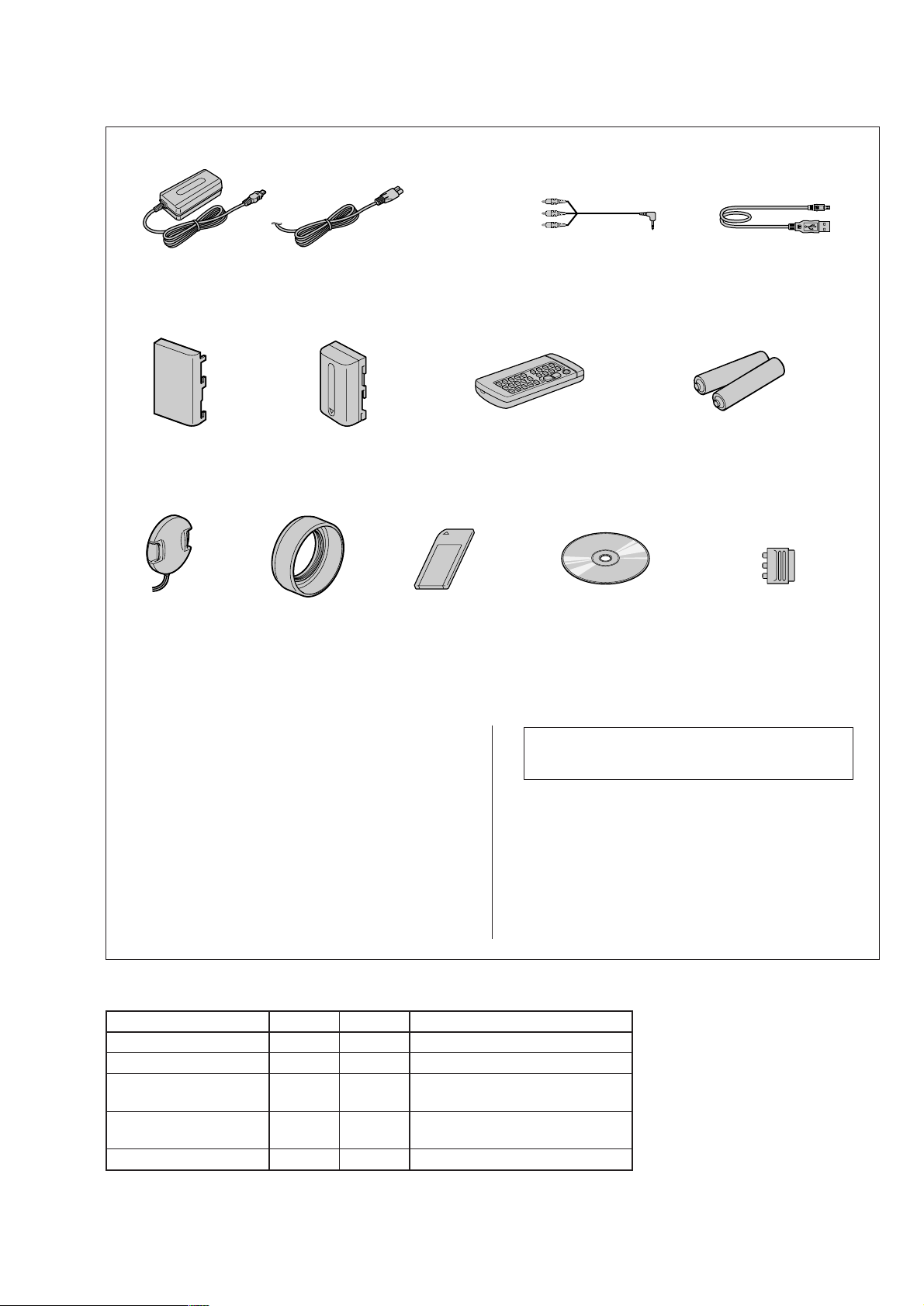
Checking supplied accessories.
Make sure that the following accessories are supplied with your camcorder.
DCR-PC115E/PC120E
AC power adaptor (1)
(AC-L10A)
0
1-475-599-11
Battery terminal cover (1)
3-057-482-01
Lens cap (1)
X-3949-944-1
Power cord (Main lead)(1) (AEP model)
0
1-769-608-11
Power cord (Main lead)(1) (UK model)
0
1-783-374-11
NP-FM50 battery pack (1)
(Not supplied)
Lens hood (1)
3-063-515-01
Memory stick (1)
MSA-8A
A-7024-735-A
Other accessories
3-070-988-11 MANUAL, INSTRUCTION (ENGLISH/RUSSIAN)
3-070-988-21 MANUAL, INSTRUCTION (ITALIAN/GREECE) (PC115E)
3-070-988-31 MANUAL, INSTRUCTION (SPANISH/PORTUGUESE)
3-070-988-41 MANUAL, INSTRUCTION (FRENCH/GERMAN)
3-070-988-51 MANUAL, INSTRUCTION (ENGLISH/DUTCH)
(PC115E/PC120E:UK)
(PC120E:AEP)
(PC120E:AEP)
A/V connecting cable (1.5m) (1)
1-765-080-11
Wireless Remote Commander (1)
RMT-811
1-475-950-21
CD-ROM
(SPVD-004(P) USB Driver)(1)
3-066-676-01
Note : The components identified by mark 0 or dotted
line with mark 0 are critical for safety.
Replace only with part number specified.
(PC115E)
USB cable (1)
1-757-293-21
Size R6 (AA) battery for
Remote Commander (2)
(not supplied)
21-pin adaptor (1)
1-573-291-11
3-071-132-11 OPERATING INSTRUCTION(NETWORK)
3-071-132-21 OPERATING INSTRUCTION(NETWORK)
(ENGLISH/FRENCH)(PC120E)
(GERMAN/DUTCH) (PC120E:AEP)
Table for difference of functions
DCRDestination
NETWORK (Bluetooth)
Flash memory
PC115E
AEP
✕
4Mbit
PC120E
AEP, UK
32Mbit
(VC-270 board IC1406)
SDRAM
16Mbit
64Mbit
(VC-270 board IC1404)
BT-003 board
✕
Remarks
X301 of VC-270 board is 40.5MHz.
a
With BT-003 board
a
— 3 —

DCR-PC115E/PC120E
TABLE OF CONTENTS
SERVICE NOTE
1. POWER SUPPLY DURING REPAIRS ····························· 5
2. TO TAKE OUT A CASSETTE WHEN NOT EJECT
(FORCE EJECT) ································································5
3. DISCHARGING OF THE FLASHLIGHT POWER
SUPPLY CAPACITOR ······················································ 6
3-1. DISCHARGING THE CAPACITOR USING THE
SHORT JIG ········································································ 6
3-1-1.PREPARING THE SHORT JIG········································· 6
3-1-2.DISCHARGING THE CAPA CIT OR································· 6
3-2. DISCHARGING THE CAPACITOR USING THE
REMOTE COMMANDER ················································ 6
3-2-1.DISCHARGING THE CAPA CIT OR································· 6
3-2-2.PROCESSING AFTER COMPLETING REPAIRS/
ADJUSTMENTS································································ 6
SELF-DIAGNOSIS FUNCTION
1. SELF-DIAGNOSIS FUNCTION······································· 7
2. SELF-DIAGNOSIS DISPLAY ·········································· 7
3. SERVICE MODE DISPLAY ············································· 7
3-1. Display Method ·································································· 7
3-2. Switching of Backup No. ··················································· 7
3-3. End of Display···································································· 7
4. SELF-DIAGNOSIS CODE TABLE··································· 8
1. MAIN PARTS
1. ORNAMENTAL PARTS···················································· 9
2. DISASSEMBLY······························································· 10
2-1. CABINET (L) SECTION················································· 12
2-2. VTR COMPLETE, CABINET (R) SECTION ················ 13
2-3. FJ-035 BOARD································································ 14
2-4. VM-027 BOARD ····························································· 15
2-5. CD-349P BOARD, LENS DEVICE ································ 15
2-6. VC-270 BOARD ······························································ 16
2-7. MECHANISM DECK······················································ 16
2-8. FLASH UNIT (MC) ·························································17
2-9. FLASH UNIT (ST) ·························································· 17
2-10. CABINET (G) BLOCK ASSEMBLY, ETC.···················· 18
2-11. CONTROL SWITCH BLOCK (FK-1850) ······················ 19
2-12. CONTROL SWITCH BLOCK (PS-1850) ······················· 19
2-13. BLIND PLATE ASSEMBLY ···········································20
PD-148B BOARD, INVERTER TRANSFORMER UNIT ·
2-14.
2-15. HINGE ASSEMBLY························································ 21
3. REPAIR PARTS LIST ······················································ 22
3-1. EXPLODED VIEWS ······················································· 22
3-1-1.OVERALL SECTION······················································ 22
3-1-2.CABINET (L) SECTION················································· 23
3-1-3.VTR OVERALL SECTION············································· 24
3-1-4.LENS-EVF SECTION ····················································· 25
3-1-5.CABINET (R) SECTION-1 ············································· 26
3-1-6.CABINET (R) SECTION-2 ············································· 27
2. GENERAL
Main Features ············································································· 28
Quick Start Guide ······································································· 28
Getting started
Using this manual ··································································· 29
Checking supplied accessories ··············································· 29
Step 1 Preparing the power supply ········································· 30
Installing the battery pack···················································· 30
Charging the battery pack ····················································30
Connecting to a wall socket ·················································31
Step 2 Setting the date and time ············································· 31
Step 3 Inserting a cassette······················································· 32
Recording – Basics
Recording a picture·································································32
Shooting backlit subjects – BACK LIGHT ···························· 35
Shooting in the dark – NightShot/Super NightShot ··············· 35
Self-timer recording································································ 35
Checking the recording – END SEARCH / EDITSEARCH /
Rec Review ··········································································36
Playback – Basics
Playing back a tape ································································· 36
20
To display the screen indicators – Display function ··············· 36
Viewing the recording on TV ················································· 37
Advanced Recording Operations
Recording a still image on a tape – Tape Photo recording ····· 38
Adjusting the white balance manually···································· 39
Using the wide mode ······························································ 40
Using the fader function ························································· 40
Using special effects – Picture effect······································ 41
Using special effects – Digital effect······································ 41
Using the PROGRAM AE function ········································ 42
Adjusting the exposure manually ··········································· 43
Focusing manually·································································· 43
Interval recording···································································· 44
Frame by frame recording – Cut recording ····························44
Advanced Playback Operations
Playing back a tape with picture effects ································· 45
Playing back a tape with digital effects ·································· 45
Enlarging images recorded on tapes – Tape PB ZOOM ·········45
Quickly locating a scene using the zero set memory function·····
Searching the boundaries of recorded tape by title – Title search ·
Searching a recording by date – Date search·························· 47
Searching for a photo – Photo search/Photo scan··················· 47
Editing
Dubbing a tape ········································································48
Dubbing only desired scenes – Digital program editing (on tapes) ··
Using with analog video unit and your computer
– Signal convert function····················································· 52
Recording video or TV programmes ······································ 53
Inserting a scene from a VCR – Insert editing························ 54
Audio dubbing ········································································ 55
Superimposing a title ······························································ 56
Making your own titles ···························································57
Labelling a cassette································································· 57
Customising Y our Camcorder
Changing the menu settings···················································· 58
“Memory Stick” Operations
Using a “Memory Stick” – introduction ·································60
Recording still images on “Memory Stick”s
– Memory Photo recording ··················································63
Recording an image from a tape as a still image ···················· 65
Superimposing a still image in the “Memory Stick” on an
image – MEMORY MIX····················································· 66
Recording moving pictures on “Memory Stick”s
– MPEG movie recording ····················································68
Recording a picture from a tape as a moving picture ············· 68
Recording edited pictures as a moving picture
– Digital program editing (on “Memory Stick”s)················ 69
Copying still images from a tape – Photo save······················· 70
Viewing a still image – Memory photo playback ··················· 71
Viewing a moving picture – MPEG movie playback ············· 72
Viewing images using computer ············································· 72
Copying the image recorded on “Memory Stick”s to tapes ····
Enlarging still images recorded on “Memory Stick”s
– Memory PB ZOOM ··························································75
Playing back images in a continuous loop – SLIDE SHOW·····
Preventing accidental erasure – Image protection ·················· 76
Deleting images ······································································ 76
Writing a print mark – PRINT MARK··································· 76
Using the optional printer ······················································· 77
Using the Network function
Accessing the network ····························································77
Troubleshooting
Types of trouble and their solutions ········································78
Self-diagnosis display ·····························································79
Warning indicators and messages ··········································· 79
Additional Information
Usable cassettes ······································································ 80
About the “InfoLITHIUM” battery pack································ 81
About i.LINK·········································································· 81
Using your camcorder abroad················································· 82
Maintenance information and precautions······························ 82
Quick Reference
Identifying the parts and controls ··········································· 84
46
46
49
74
75
— 4 —
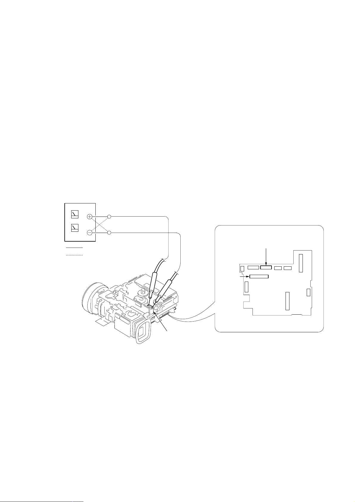
SERVICE NOTE
: Unloading
: Loading
VC-270 board
Loading motor
Regulated power supply
(+4.5Vdc)
CN006
CN302
DCR-PC115E/PC120E
1. POWER SUPPLY DURING REPAIRS
In this unit, about 10 seconds after power is supplied to the battery terminal using the regulated power supply (8.4V), the po wer is shut of f so
that the unit cannot operate.
This following two methods are available to prevent this. Take note of which to use during repairs.
Method 1
Use the AC power adaptor (AC-L10, AC-VQ800, AC-SQ950 etc.).
Method 2
Connect the servicing remote commander RM-95 (J-6082-053-B) to the LANC jack, and set the commander switch to the “ADJ” side.
2. TO TAKE OUT A CASSETTE WHEN NOT EJECT (FORCE EJECT)
1 Refer to 2-2. to remove the HS cover.
2 Refer to 2-2. to remove the jack cover.
3 Refer to 2-2. to remove the cabinet (R) assembly.
4 Refer to “3. DISCHARGING OF THE FLASHLIGHT POWER SUPPL Y CAPACITOR” to dischar ge the flash power supply capacitor .
5 Refer to 2-3. to remove the mechanism deck and the lens block and the EVF block from the cabinet (L) block.
6 Disconnect CN302 (72P, 0.4mm) of VC-270 board.
7 Disconnect CN006 (27P, 0.3mm) of VC-270 board.
8 Supply +4.5V from the DC power supply to the loading motor and unload with a pressing the cassette compartment.
— 5 —
DCR-PC115E/PC120E
3. DISCHARGING OF THE FLASHLIGHT POWER SUPPLY CAPACITOR
The capacitor (C2010) of the flash unit (MC1850) is charged up to the maximum 300V potential. There is a danger of electric shock by this
high voltage when the flash unit (MC1850 or ST1850) is handled by hand. The electric shock is caused by the char ged v oltage which is kept
without discharging when the main power of the unit is simply turned of f. Ther efore, the remaining volta ge must be discharged as described
below.
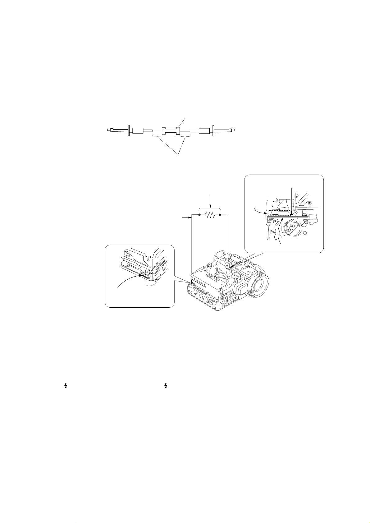
3-1. DISCHARGING THE CAPACITOR USING THE SHORT JIG
3-1-1. PREPARING THE SHORT JIG
T o preparing the short jig. a small clip is attached to each end of a resistor of 1kΩ/1W (1-215-869-11). Wrap insulating tape fully around the
reads of the resistor to prevent electric shock.
1 k
Ω
/1 W
Wrap insulating tape
3-1-2. DISCHARGING THE CAP ACIT OR
Connect the short jig with the capacitor directly.
1 k
Ω
1 Remove the power supply (Battery or AC power adaptor).
2 Short circuit between TP001 of the flash unit (MC1850) and the GND
(Chassis etc.) with the short jig about 10 seconds.
Short jig
GND
Chassis
(Sheet metal bending block)
/1 W resistor
(1-215-869-11)
C2010
Flash unit (MC1850)
3-2. DISCHARGING THE CAPACITOR USING THE REMOTE COMMANDER
3-2-1. DISCHARGING THE CAP ACIT OR
Note: Perfect discharge can’t be done in this method. (Remaining voltage = Approx. 90V)
1 Connect the power supply (Battery or AC power adaptor).
2 Set POWER switch to “CAMERA”.
3 Connect the adjustment remote commander to the LANC jack, and set the HOLD switch to the “ADJ” side.
4 Select page: 0, address: 01. and set data: 01.
5 Select page: D, address: F4. set data: 04, and press PAUSE button of the adjustment remote commander.
6 Press FLASH ( ) button and set to the forced flash mode ( ), and press PHOTO button to pop up the flash.
7 Select page: 6, address: B3. and set data: 03.
8 Select page: 6, address: B1. and set data: 01.
9 Select page: 6, address: B0. and set data: 01.
→The flash flashes, and data are returned to “00”
0 Repeat step 9, until the flash dose not flash.
After completing repairs/adjustments, perform “PROCESSING AFTER COMPLETING REPAIRS/ADJUSTMENTS”
Flash unit
(MC1850) TP001
3-2-2. PROCESSING AFTER COMPLETING REPAIRS/ADJUSTMENTS
1 Connect the power supply (Battery or AC power adaptor).
2 Set POWER switch to “CAMERA”.
3 Connect the adjustment remote commander to the LANC jack, and set the HOLD switch to the “ADJ” side.
4 Select page: 0, address: 01. and set data: 01.
5 Select page: D, address: F4. set data: 00, and press PAUSE button of the adjustment remote commander.
6 Select page: 6, address: B3. and set data: 00.
7 Select page: 6, address: B1. and set data: 00.
8 Select page: 0, address: 01. and set data: 00.
— 6 —
SELF-DIAGNOSIS FUNCTION
DCR-PC115E/PC120E
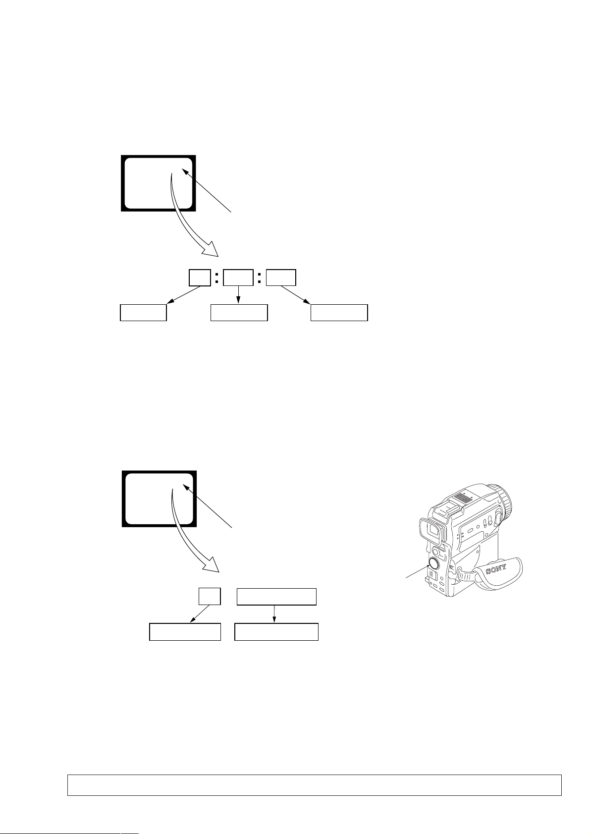
1. SELF-DIAGNOSIS FUNCTION
When problems occur while the unit is operating, the self-diagnosis
function starts working, and displays on the viewfinder or LCD
screen what to do. This function consists of two display; selfdiagnosis display and service mode display .
Details of the self-diagnosis functions are provided in the Instruction
manual.
Viewfinder or LCD screen
C : 3 1 : 1 1
Repaired by:
C : Corrected by customer
H : Corrected by dealer
E : Corrected by service
engineer
Blinks at 3.2Hz
3 1C
Block
Indicates the appropriate
step to be taken.
E.g.
31 ....Reload the tape.
32 ....Turn on power again.
1 1
2. SELF-DIAGNOSIS DISPLAY
When problems occur while the unit is operating, the counter of the
viewfinder or LCD screen consists of an alphabet and 4-digit
numbers, which blinks at 3.2 Hz. This 5-character display indicates
the “repaired by:”, “block” in which the problem occurred, and
“detailed code” of the problem.
Detailed Code
Refer to page 8.
Self-diagnosis Code Table.
3. SERVICE MODE DISPLAY
The service mode display shows up to six self-diagnosis codes shown in the past.
3-1. Display Method
While pressing the “STOP” key, set the switch from OFF to “VCR”, and continue pressing the “STOP” key for 5 seconds continuously. The
service mode will be displayed, and the counter will show the backup No. and the 5-character self-diagnosis codes.
Viewfinder or LCD screen
[3] C : 3 1 : 1 1
Lights up
Control button
[3]
Backup No.
Order of previous errors
3-2. Switching of Backup No.
By pressing up side or down side of the control button, past self-diagnosis codes will be sho wn in order. The backup No. in the [] indicates the
order in which the problem occurred. (If the number of problems which occurred is less than 6, only the number of problems which occurred
will be shown.)
[1] : Occurred first time [4] : Occurred fourth time
[2] : Occurred second time [5] : Occurred fifth time
[3] : Occurred third time [6] : Occurred the last time
C : 3 1 : 1 1
Self-diagnosis Codes
3-3. End of Display
Turning OFF the power supply will end the service mode display.
Note: The “self-diagnosis display” data will be backed up by the coin-type lithium battery (BT001) of the control switch block (FK-1850). When the
cabinet (L) assembly is removed, the “self-diagnosis display” data will be lost by initialization.
— 7 —

DCR-PC115E/PC120E
4. SELF-DIAGNOSIS CODE TABLE
Self-diagnosis Code
Function
Repaired by:
C
C
C
C
C
C
C
C
C
C
C
C
C
C
C
C
C
C
C
C
C
C
C
E
E
E
E
E
Block
04
21
22
31
31
31
31
31
31
31
31
31
31
31
31
32
32
32
32
32
32
32
32
61
61
62
62
91
Detailed
Code
00
00
00
10
11
20
21
22
23
24
30
40
42
10
11
20
21
22
23
24
30
40
42
00
10
00
01
01
Symptom/State
Non-standard battery is used.
Condensation.
Video head is dirty.
LOAD direction. Loading does not
complete within specified time
UNLOAD direction. Loading does not
complete within specified time
T reel side tape slacking when unloading
Winding S reel fault when counting the
rest of tape.
T reel fault.
S reel fault.
T reel fault.
FG fault when starting capstan.
FG fault when starting drum.
FG fault during normal drum operations.
LOAD direction loading motor time-
out.
UNLOAD direction loading motor
time-out.
T reel side tape slacking when
unloading.
Winding S reel fault when counting the
rest of tape.
T reel fault.
S reel fault.
T reel fault.
FG fault when starting capstan.
FG fault when starting drum
FG fault during normal drum
operations
Difficult to adjust focus
(Cannot initialize focus.)
Zoom operations fault
(Cannot initialize zoom lens.)
Steadyshot function does not work well.
(With pitch angular velocity sensor output
stopped.)
Steadyshot function does not work well.
(With yaw angular v elocity sensor output
stopped.)
Charging the flash does not complete
witin the specified time.
Correction
Use the info LITHIUM battery.
Remove the cassette, and insert it again after one hour.
Clean with the optional cleaning cassette.
Load the tape again, and perform operations from the beginning.
Load the tape again, and perform operations from the beginning.
.
Load the tape again, and perform operations from the beginning.
Load the tape again, and perform operations from the beginning.
Load the tape again, and perform operations from the beginning.
Load the tape again, and perform operations from the beginning.
Load the tape again, and perform operations from the beginning.
Load the tape again, and perform operations from the beginning.
Load the tape again, and perform operations from the beginning.
Load the tape again, and perform operations from the beginning.
Remove the battery or power cable, connect, and perform
operations from the beginning.
Remove the battery or power cable, connect, and perform
operations from the beginning.
Remove the battery or power cable, connect, and perform
operations from the beginning.
Remove the battery or power cable, connect, and perform
operations from the beginning.
Remove the battery or power cable, connect, and perform
operations from the beginning.
Remove the battery or power cable, connect, and perform
operations from the beginning.
Remove the battery or power cable, connect, and perform
operations from the beginning.
Remove the battery or power cable, connect, and perform
operations from the beginning.
Remove the battery or power cable, connect, and perform
operations from the beginning.
Remove the battery or power cable, connect, and perform
operations from the beginning.
Inspect the lens block focus MR sensor (Pin 8,9 of CN151 of
CD-349 board) when focusing is performed when the focus ring is
rotated in the focus manual mode, and the focus motor drive circuit
(IC201 of VC-270 board) when the focusing is not performed.
Inspect the lens block zoom MR sensor (Pin ql,wa of CN151 of
CD-349 board) when zooming is performed when the zoom lens is
operated and the zoom motor drive circuit (IC201 of VC-270 board)
when zooming is not performed.
Inspect pitch angular velocity sensor (SE3450 of VM-027 board)
peripheral circuits.
Inspect yaw angular velocity sensor (SE3451 of VM-027 board)
peripheral circuits.
Inspect the flash unit (ST1850 and MC1850).
— 8 —
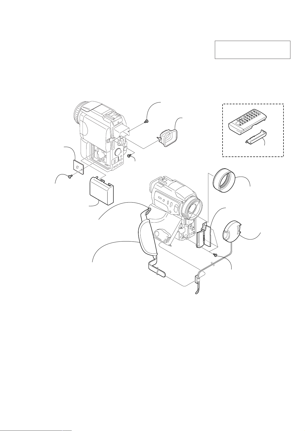
1. MAIN PARTS
Jack ornamental cover assembly
X-3951-962-1
VF lens assembly
X-3951-894-1
Lens cap assembly
X-3949-944-1
Lens hood
3-063-515-01
Grip belt
Remote commander (RMT-811)
1-475-950-21
Battery case lid (for RMT-811)
3-053-056-01
Jack cover (G)
Note: Disassembling the main unit
is necessary to replace it.
Note: Disassembling the main unit
is necessary to replace it.
Lockace (M1.7)
3-057-437-01
Three screws
(M1.7), lockace, P2
3-989-735-01
Screw
(M1.7), lockace, P2
3-989-735-01
Screw
(M1.7), lockace, P2
3-989-735-01
CPC lid
3-070-369-01
Battery cover
3-057-482-01
Note:
• Follow the disassembly procedure in the numerical order given.
• Items marked “*” are not stocked since they are seldom required for routine service.
Some delay should be anticipated when ordering these items.
• The parts numbers of such as a cabinet are also appeared in this section.
Refer to the parts number mentioned below the name of parts to order.
1. ORNAMENTAL PARTS
DCR-PC115E/PC120E
The components identified by mark 0 or
dotted line with mark 0 are critical for safety.
Replace only with part number specified.
— 9 —

DCR-PC115E/PC120E
2. DISASSEMBLY
The following flow chart shows the disassembly procedure.
2-1. Cabinet (L) section
2-2. VTR complete, Cabinet (R) section
2-10. Cabinet (G) block assembly, etc
2-11. Control switch block (FK-1850)
2-12. Control switch block (PS-1850)
2-3. FJ-035 board
2-4. VM-027 board
DCR-PC115E/PC120E
2-5. CD-349P board, Lens device
2-6. VC-270 board
2-7. Mechanism deck
2-8. Flash unit (MC)
2-9. Flash unit (ST)
2-13. Blind plate assembly
2-14. PD-148B board,
Inverter transformer unit
2-15. Hinge assembly
— 10 —
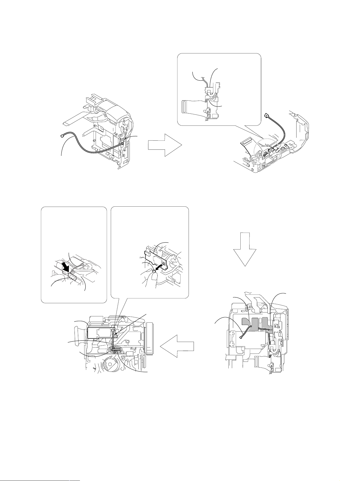
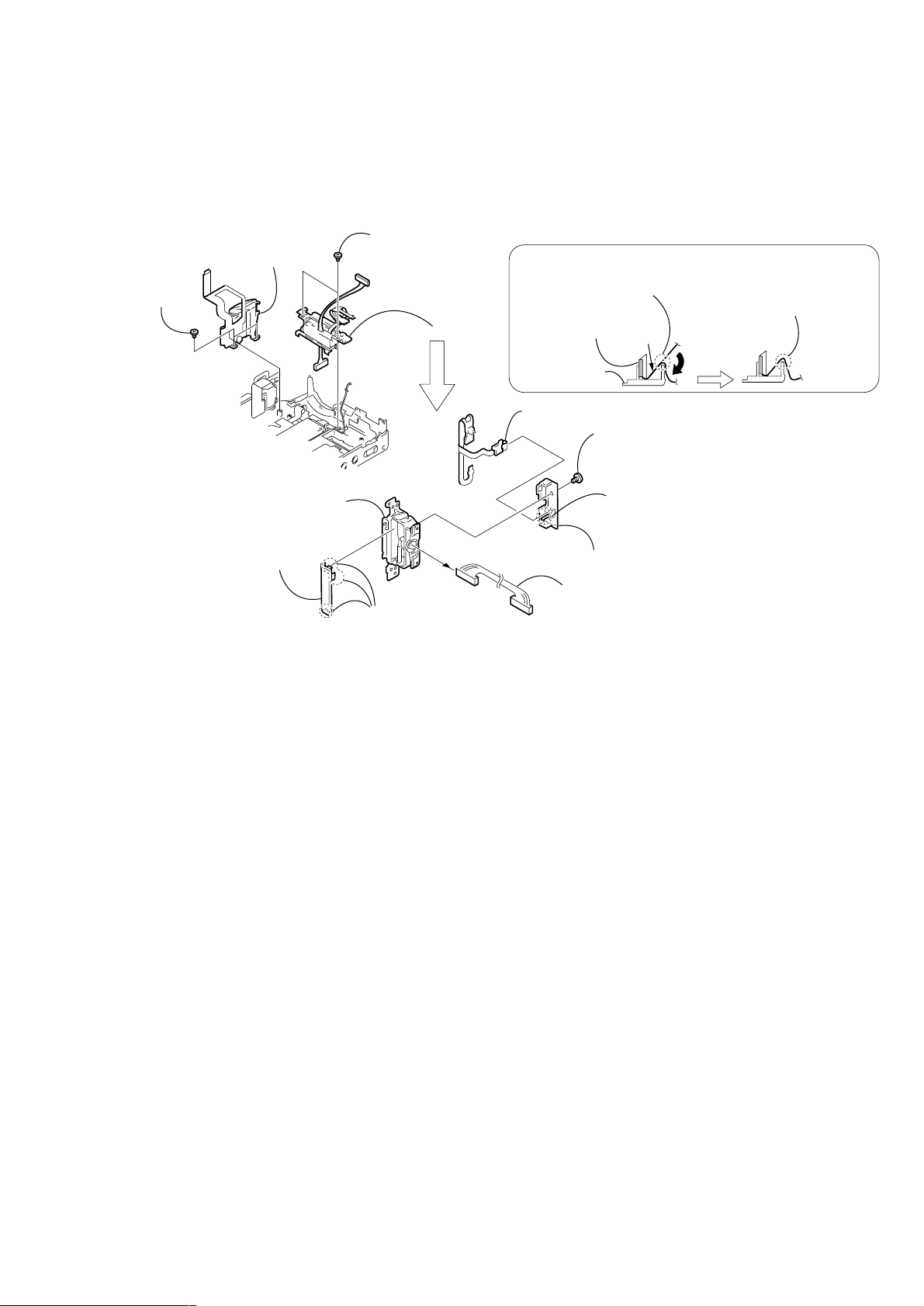
[Routing the Bluetooth BT cable] (PC120E)
DCR-PC115E/PC120E
BT cable
Pass the cable through the hole A of the
1
Cabinet (R) section.
Route the cable through the
clearance
it on the clearance between
the BT cable guide and
lens device.
B
, and then hook
BT cable
When removing the BT cable
from the BT-003 board, be sure
to hold the connector of the
BT-003 cable and remove it.
A
BT-003
board
BT cable
2
board of the FJ-035 board and route it under the
flexible board of the FJ-035 board.
3
FJ-035 board.
Rigid portion of the
FJ-035 board
Flexible board of
the FJ-035 board
Draw the cable through clearance of the flexible
Route the cable under the rigid portion of the
Connector of
BT cable
BT cable
guide
BT-003 board
BT cable
6
Route the cable through the clearance B.
7
Insert it to the connector on the BT-003 board.
Lens device
B
Attach the BT cable so
that it stretches straight
downward.
BT cable
guide
BT cable
sheet
BT cable
4
Insert it into the notch of the lens rubber (R).
5
Insert it into the notch of the BT cable sheet.
Lens
rubber (R)
— 11 —
DCR-PC115E/PC120E
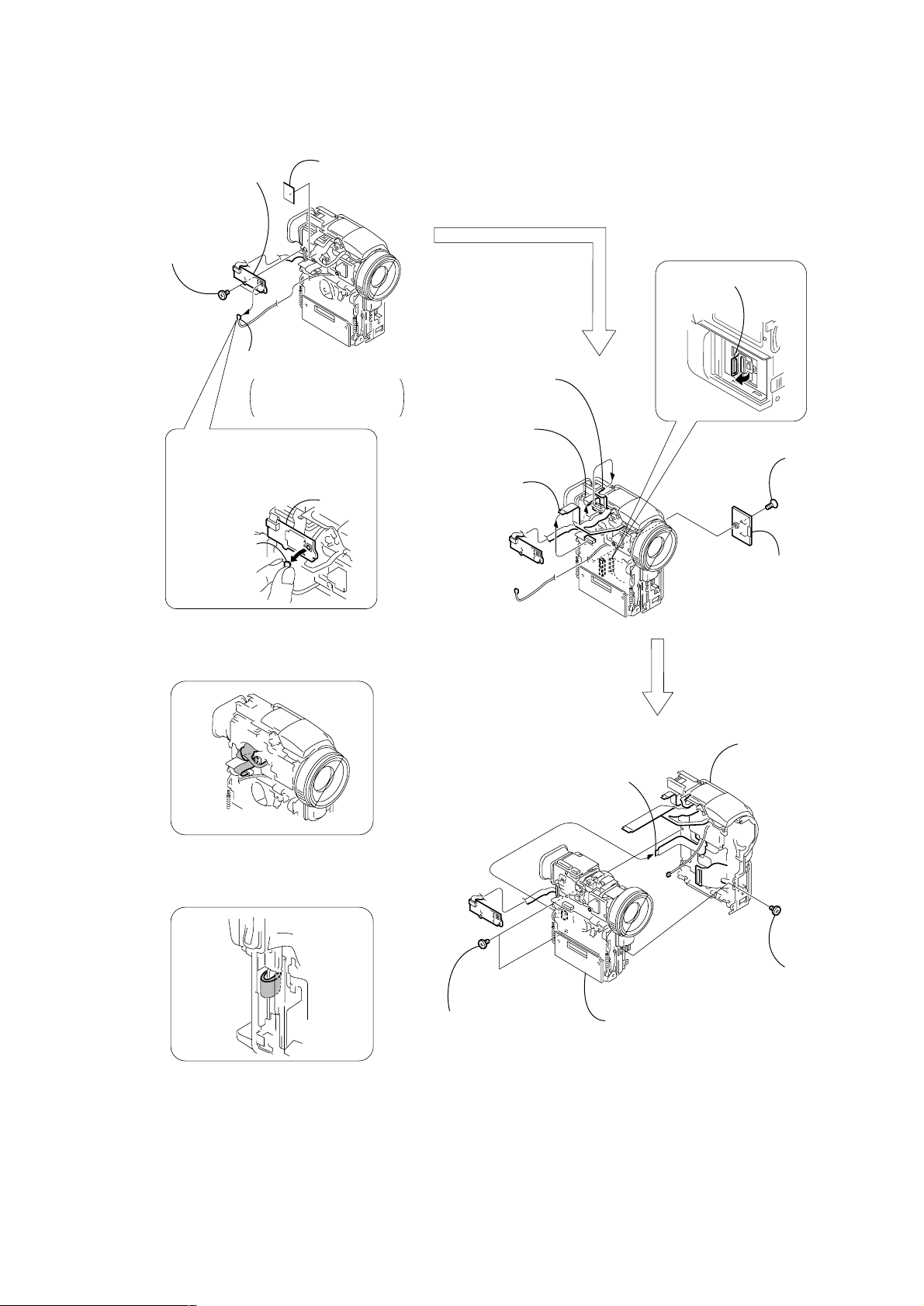
NOTE: F ollo w the disassembly procedure in the numerical order given.
2-1. CABINET (L) SECTION
Note: The power capacitor (C2010) of the flash unit is charged to the high tension voltage as high as 300 V at a maximum.
You will get electrical shock when you touch the Flash unit (MC) mounted with the terminal of the charged capacitor.
The charged potential remains even after the main power of the machine is turned off.
Discharge the remaining power in the capacitor referring to Service Note (page 6).
PRECAUTION DURING
JACK ORNAMENTAL COVER
ASSEMBLY INSTALLATION
Be careful that top of the Jack
ornamental cover assembly does not
hang over the IR window assembly.
1
Screw
(M1.7 × 2.5),
lock ace, p2
3
HS Cabinet
2
T wo claws
4
Three screws
(M1.7 × 2.5),
lock ace, p2
OK NG
IR window
assembly
Jack ornamental
cover assembly
5
Jack ornamental
cover assembly
3
(M1.7 × 4),
lock ace, p2
PRECAUTION DURING CABINET (L) SECTION
INSTALLATION
When installing the Cabinet (L) section to the Cabinet (R) section
and to the VTR complete, install it while the "Night-Shot switch
outside the Cabinet (L) section" and "Night-Shot switch on top of
the Lens Device" are facing upward.
1
Screw
(M1.7
lock ace, p2
T wo screws
×
2.5),
7
Cabinet (L) section
5
Control switch block
(FK-1850) (51P)
6
Cabinet (R) section,
VTR complete
4
Screw
(M1.7 × 2.5),
lock ace, p2
(Caution:
High voltage)
Flash unit (MC)
2
T wo screws
(M1.7 × 2.5),
lock ace, p2
OFF
ON
Night-Shot switch outside the
Cabinet (L) section
Night-Shot switch on top of
the Lens Device
Lens Device
— 12 —
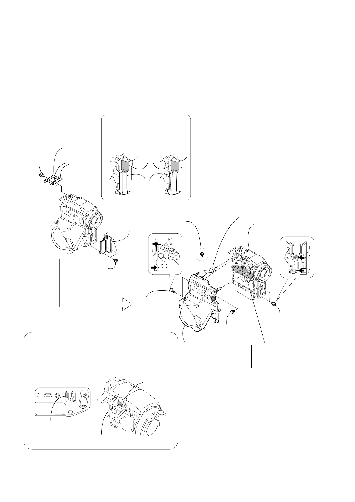
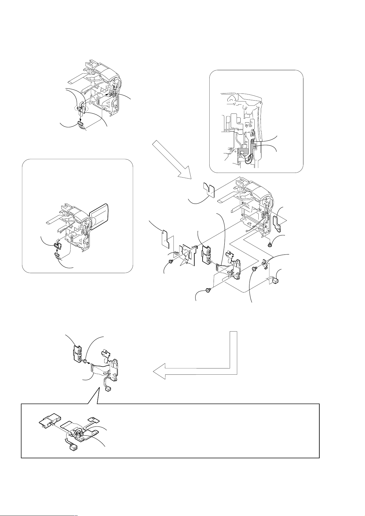
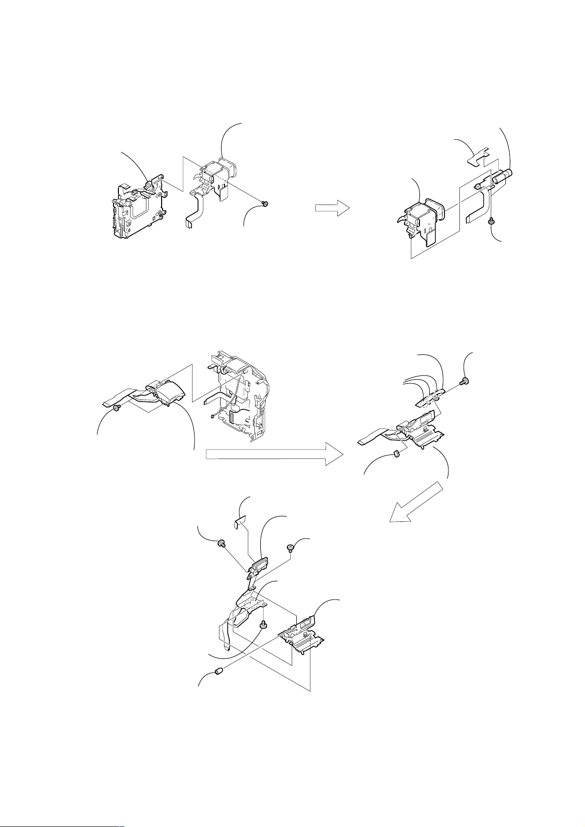
2-2. VTR COMPLETE, CABINET (R) SECTION
4
FK flexible guard
6
BT-003
board
Flash unit (ST) (33P)
5
Microphone unit (5P)
4
board (27P)
2
T wo screws
(M1.4 × 2),
lock ace
(PC120E)
3
BT-003 board
(PC120E)
1
Antenna (2.4GHz)
(PC120E)
See to "Routing the
Bluetooth BT cable" when
re-assembling parts
When removing the BT cable
from the BT-003 board, be sure
to hold the connector of the
BT-003 cable and remove it.
FP-385 flexible
DCR-PC115E/PC120E
3
FJ-035 board (88P)
1
Screw
(M1.7
lock ace, k3
×
2.5),
Connector of
BT cable
Routing of the flexible board of the
Operation Flash unit (ST) when
attaching the Cabinet (L) section.
Routing of the flexible board of the
Operation FP-383 flexible board when
attaching the Cabinet (L) section.
3
FP-383 flexible board
(15P)
2
T wo screws
(M1.7 × 2.5),
lock ace, p2
5
VTR complete
2
CPC lid
4
Cabinet (R) section
1
Screw
(M1.7 × 2.5),
lock ace, p2
— 13 —
DCR-PC115E/PC120E
r
2-3. FJ-035 BOARD
2
T wo claws
4
Harness
(PT-128) (16P)
PRECAUTION DURING
HARNESS (PT-128) INSTALLATION
The harness (PT-128) is pulled when the LCD
panel is opened and is loosened when closed.
When the harness (PT-128) is going to be
inserted into the connector on the FJ-035 board
and when hooking the two claws of the rigid
portion of the FJ-035 board, perform these
works while the LCD panel is opened.
3
FJ-035 board
1
FP-387 flexible board
(6P)
1
BT cable sheet
PRECAUTION DURING RIGID PORTION
OF FJ-035 BOARD INSTALLATION
Attach the FJ-035 board so that the
harness (PT-128) is routed under the
rigid portion of the FJ-035 board.
Harness
(PT-128)
Rigid portion
of FJ-035 board
FJ-035 board
2
Battery terminal board
(Note)
3
FJ-035 board,
DC-IN connector
(Note)
Harness (PT-128)
1
(Note)
3
MS flexible
sheet
5
BT terminal
retainer
4
(M1.7 × 2.5),
lock ace, p2
Battery terminal board (3P)
qs
FJ-035 board
7
Battery terminal
board
T wo screws
6
T wo screws
(M1.7 × 2.5),
lock ace, p2
qa
connector
8
Screw
(M1.7 × 2.5),
lock ace, p2
2
Lens
rubber (R)
9
Screw
(M1.7 × 2.5),
lock ace, p2
q;
DC retaine
plate
DC-IN
Battery terminal
board
DC-IN connector
FJ-035 board
CN1334
(Blue)
CN1335 (White)
Note:
CN1335 (for the DC-IN connector) and CN1334 (for the battery terminal board)of
FJ-035 board are the same size, and the number of the pins is the same.
So these connectors may be mistaken for each other. When these connectors
are mistaken, the charge system of the unit may break.
So ascertain the color of the connector when assembling these connectors.
CN1334 (for the battery terminal board) ········ Blue
CN1335 (for the DC-IN connector) ················· White
— 14 —
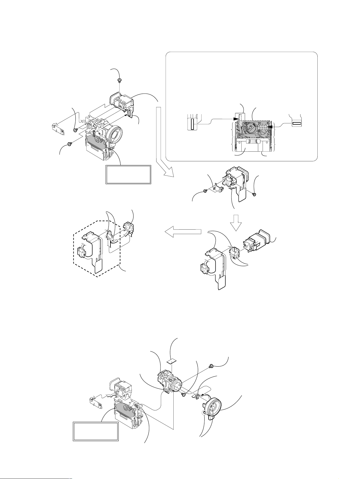
2-4. VM-027 BOARD
Mechanism deck
Cassette compartment cover
CD-349 board (72P)
Drum or Pinch arm of
Mechanism deck
VM-027 board (88P)
VC-270 board
9
qs
5
"B" of the
chassis
"B" of the
chassis
"A" of the
chassis
"A" of the
chassis
Note: If the drum or pinch arm of mechanism deck is pressed down,
the mechanism deck may not work correction.
Also if you touch the "B" portion of the chassis of the mechanism
deck as shown in the illustration, grease will adhere your hands.
When inserting the connector (88P) of the VM-027 board and the
connector (72P) of the CD-349 board into the VC-270 board
connectors, hold the "A" block of the chassis or the cassette
compartment cover of mechanism deck and insert them.
(Note)
Drum or Pinch arm
of Mechanism deck
8
VF Frame (B)
7
Two precision screws
(dia,1.7 × 4)
3
Two tapping screws
(M1.7 × 3)
2
Screw
(M1.7 × 2.5),
lock ace, p2
4
Screw
(M1.7 × 2.5),
lock ace, p2
6
Screw
(M1.7 × 2.5),
lock ace, p2
qa
VF lens assembly,
Sleeve assembly,
VF regulation ring
1
VM-027
board (88P)
q;
T wo claws
qd
T wo claws
qf
Light guide plate block,
LCX033AN-1, etc
qg
VM-027 board,
VM guard sheet
y
DCR-PC115E/PC120E
2-5. CD-349P BOARD, LENS DEVICE
9
Lens device,
CD-349P board, etc
1
CD-349P board (72P)
3
FK flexible guard
7
(M1.7 × 2.5),
lock ace, p2
Screw
2
Screw
(M1.7 × 2.5),
lock ace, p2
4
Control switch block
(MF-30550) (8P)
6
MF base assembly,
Control switch block
(MF-30550),
IR window assembl
(Note)
Drum or Pinch arm
of Mechanism deck
8
Claw
— 15 —
5
Two dowels
DCR-PC115E/PC120E
)
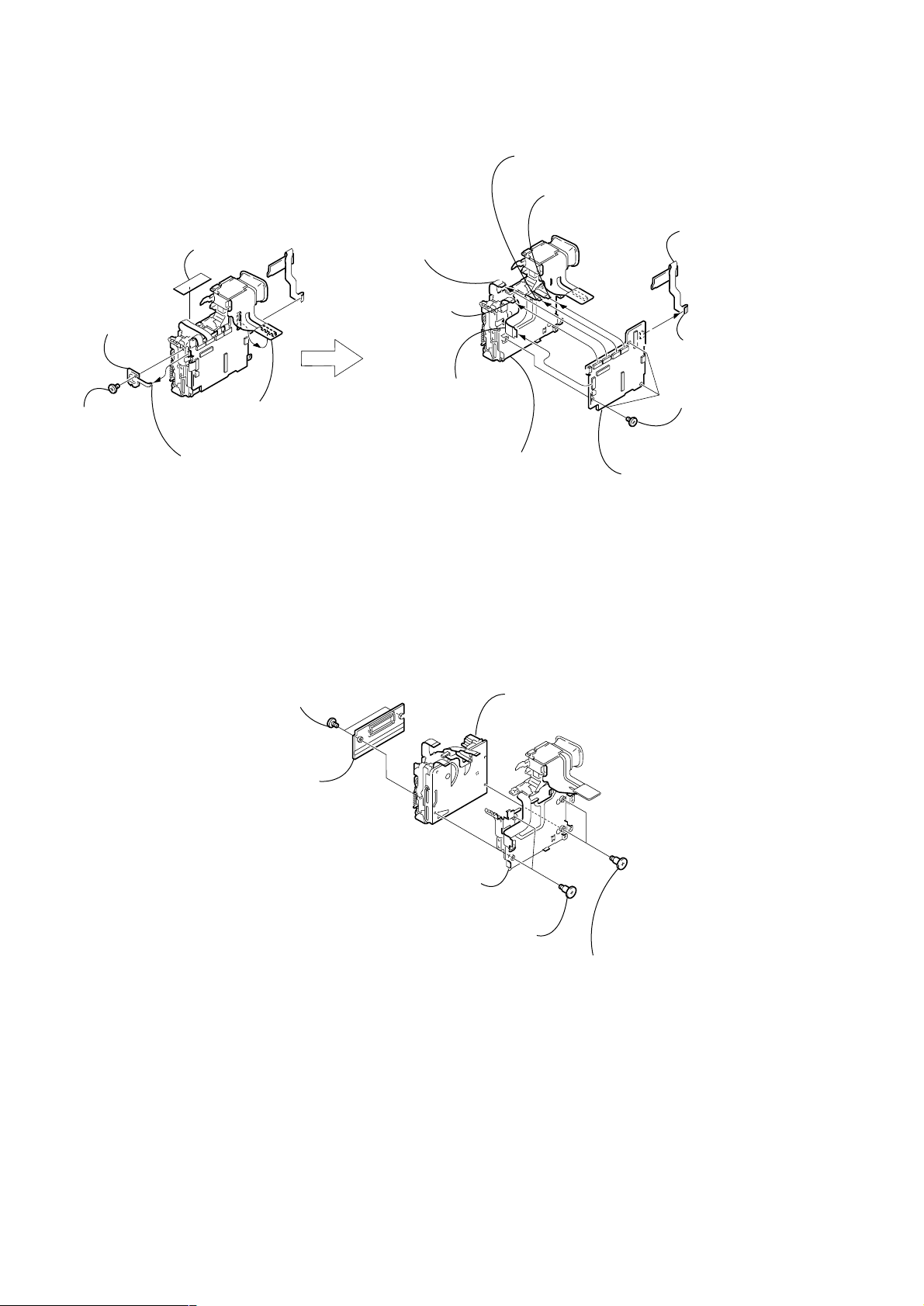
2-6. VC-270 BOARD
5
VF tape
3
FP-386 board
1
Screw
(M1.7 × 2.5),
lock ace, p2
2
FP-386 board (6P)
4
VM-027 board (88P)
2
FP-102 Flexible board
(27P)
1
Flexible board (27P)
(from capstan motor)
6
Flexible board (27P)
(from Flash unit (MC))
3
Flexible board (10P)
(from video head)
4
Flexible board (10P)
(from drum motor)
7
Mechanism deck,
Flash unit (MC),
EVF block assembly, etc
q;
VC-270 board
9
BT-003 board
(PC120E),
FP-384 flexible board
(PC120E)
8
FP-384 flexible board
(PC120E)
(15P)
5
Three screws
(M1.7 × 2.5),
lock ace, p2
2-7. MECHANISM DECK
5
Cassette compartment
cover
4
T wo screws
(M1.7 × 2.5),
lock ace, p2
3
EVF block assembly,
Flash unit (MC),
MD frame assembly, etc
2
T wo screws
(M1.4 × 1.5)
6
Mechanism deck
1
T wo screws
(M1.4
×
1.5
— 16 —
2-8. FLASH UNIT (MC)
2
Mechanism deck,
MD frame assembly
3
EVF block assembly,
VF frame assembly
Flash unit (MC),
MC guard sheet
1
Screw
(M1.7
lock ace, p2
×
2.5),
3
MC guard sheet
2
EVF block assembly,
VF frame assembly
DCR-PC115E/PC120E
4
Flash unit (MC)
1
T wo screws
(M1.7 × 2.5),
lock ace, p2
2-9. FLASH UNIT (ST)
1
T wo screws
(M1.7
lock ace, p2
×
2.5),
4
(M1.7
lock ace, p2
2
Screw
×
2.5),
1
Insulating sheet (ST)
8
Flash unit (ST)
6
Peel off the
adhesive side.
5
4
3
Bolt
(M1.4 × 3)
7
Stroboscope assembly,
ST cabinet lower
ST cabinet upper
Three claws
6
Stroboscope
cushion (A)
7
3
Precision screw
(dia, 1.7
×
4)
5
Screw
(M1.7 × 2.5),
lock ace, p2
2
precision screw
Hexagon hole
— 17 —
DCR-PC115E/PC120E
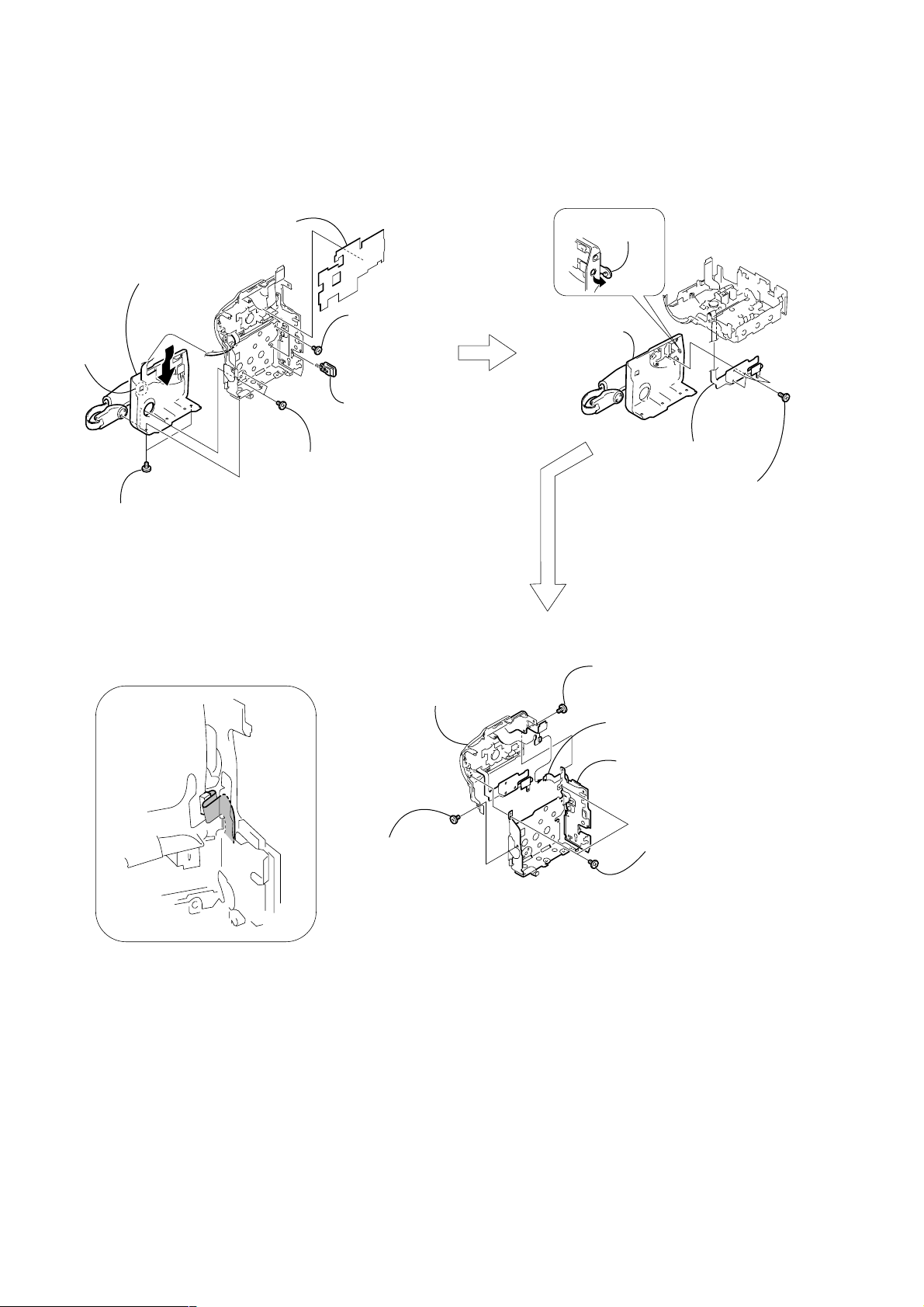
2-10. CABINET (G) BLOCK ASSEMBLY, ETC.
Note:
The +P2 (0-No.) screws (M1.7 × 2.5) are MEC-processed. If the screws that are once removed,
are re-used, the screws may be loosened.
When re-assembling the mechanism, use the new +P2 (0-No.) screws (M1.7
2
Sheet (L)
7
Cabinet (G) assembly,
Control switch block
(FK-1850)
6
Claw
3
(M1.7
0-No, +p2
4
T wo screws
(M1.7 × 2.5),
lock ace, p2
(Note)
5
T wo screws
(M1.7
lock ace, p2
1
Compression spring
T wo screws
×
2.5),
Battery lock,
×
2.5),
×
2.5).
3
assembly
1
Jack
cover (G)
Cabinet (G)
4
Control switch block
(FK-1850)
2
(dia, 1.7
Four precision
screws
×
4)
Routing of the flexible board of the
Operation Control switch block (FK-1850)
when attaching the G frame assembly,
Cabinet (rear) assembly.
6
Cabinet (L),
Control switch block
(FK-1850)
2
Screw
(M1.7 × 2.5),
lock ace, p2
1
Screw
(M1.7
lock ace, p2
×
2.5),
4
Control switch block
(PS-1850) (15P)
5
G frame assembly,
Cabinet (rear) assembly,
Control switch block (PS-1850),
KY-060 board
3
T wo screws
(M1.7
lock ace, p2
×
2.5),
— 18 —
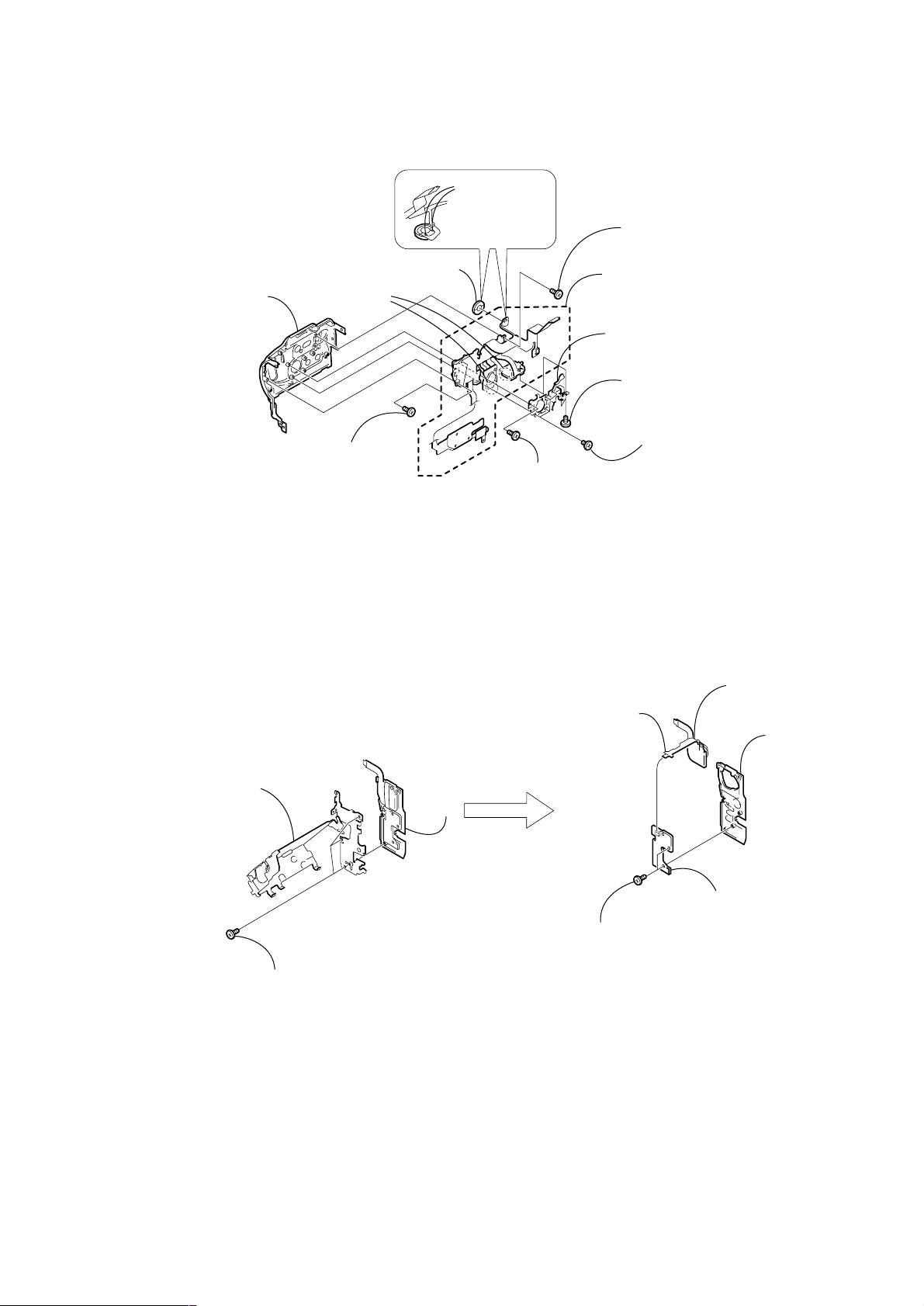
2-11. CONTROL SWITCH BLOCK (FK-1850)
)
q;
Speaker
5
Cabinet (L)
7
T wo claws
3
T wo screws
(M1.7 × 2.5),
lock ace, p2
9
Remove the
two solderings
2
Precision screw
(dia, 1.7
DCR-PC115E/PC120E
4
Precision screw
(dia, 1.7
qa
Control switch block (FK-1850
8
Jack frame assembly
6
T wo screws
(M1.7 × 2.5),
lock ace, p2
1
(M1.7 × 2.5),
lock ace, p2
×
4)
×
4)
Four screws
2-12. CONTROL SWITCH BLOCK (PS-1850)
2
G frame assembly
1
Three precision
screws
(dia, 1.7
×
4)
3
8
Control switch block
6
Control switch block
(PS-1850) (7P)
4
Two precision screws
(dia, 1.7 × 4)
(PS-1850)
5
assembly
7
KY-060 board
Cabinet (rear)
— 19 —
DCR-PC115E/PC120E
2-13. BLIND PLATE ASSEMBLY
(Remove the FJ-035 board referring to section 2-3 before starting disassembling.)
Note:
The +P2 (0-No.) screws (M1.7 × 2.5) are MEC-processed. If the screws that are once removed,
are re-used, the screws may be loosened.
When re-assembling the mechanism, use the new +P2 (0-No.) screws (M1.7
1
T wo screws
(M1.7
0-No, +p2
(Note)
×
2.5),
2
FP-387 flexible board
A
A
1
Four claws
If the FP-387 flexible board is
pulled in the direction of the
arrow
locations will be released.
2
Blind plate assembly
Remove it while taking care so that it must not
be caught by the flexible board and harnesses,
by pulling it in the direction of the arrow.
A
, the claws at the four
×
2.5).
PRECAUTION DURING
FP-387 FLEXIBLE BOARD
INSTALLATION (1)
Install the flexible wire to the blind plate
so that it covers the harness (PT-128).
Remove the blind plate assembly
after opening the LCD panel.
Blind plate
assembly
Harness (PT-128)
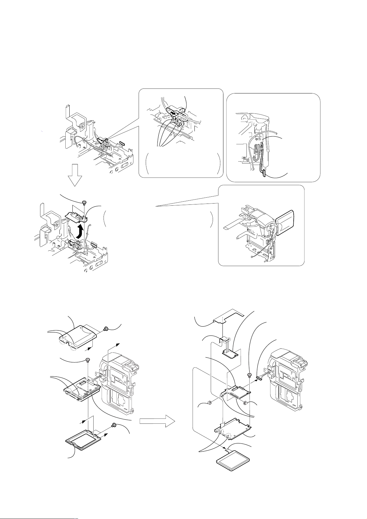
2-14. PD-148B BOARD, INVERTER TRANSFORMER UNIT
2
3
LCD cabinet (R)
assembly
2
T wo claws
5
T wo screws
(M1.7 × 2.5),
lock ace, p2
6
T wo claws
7
LCD cabinet (L)
assembly
B
A
PD-148B
1
(M1.7 × 2.5),
lock ace, p2
B
A
T wo screws
8
4
T wo screws
(M1.7 × 2.5),
MI
Panel insulating
sheet
4
Remove the
three solderings
qs
PD-148B board
6
T wo claws
8
PCB clip
qa
Inverter transformer unit
5
Screw
(M1.7
lock ace, p2
1
(PT-128) (16P)
PD-148B
9
PCB clip
q;
Remove the
six solderings
7
Back light
(Cold cathode fluorescent tube)
3
Liquid crystal
indicator module (24P)
×
2.5),
Harness
— 20 —
2-15. HINGE ASSEMBLY
4
A
Give the folding line along with
the hinge cover (lower) while
taking care so that the portion
A
is not loosened.
Be careful that the margin
between the flexible board
and the hinge cover (lower)
is around 1 mm.
3
T wo screws
(M1.7
×
2.5),
lock ace, p2
1
T wo screws
(M1.7
×
2.5),
lock ace, p2
qs
Hinge assembly
q;
Hinge cover (upper)
8
Hinge cover (lower)
Hinge cover
(lower)
2
Strobe unit
9
Three claws
6
Claw
5
Screw
(M1.7
×
2.5),
0-No, +p2
(Note)
PRECAUTION DURING FP-387 FLEXIBLE
BOARD INSTALLATION (2)
7
FP-387 flexible board
FP-387 flexible
board
qa
Harness (PT-128)
The +P2 (0-No.) screws (M1.7 × 2.5) are MEC-processed. If the screws that are once removed,
are re-used, the screws may be loosened.
When re-assembling the mechanism, use the new +P2 (0-No.) screws (M1.7
×
2.5).
Note:
(Remove the LCD unit referring to section 2-14 before starting disassembling.)
DCR-PC115E/PC120E
— 21 —
DCR-PC115E/PC120E
3. REPAIR PARTS LIST
3-1. EXPLODED VIEWS
NOTE:
• -XX, -X mean standardized parts, so they may
have some differences from the original one.
• Items marked “*” are not stocked since they
are seldom required for routine service. Some
delay should be anticipated when ordering these
items.
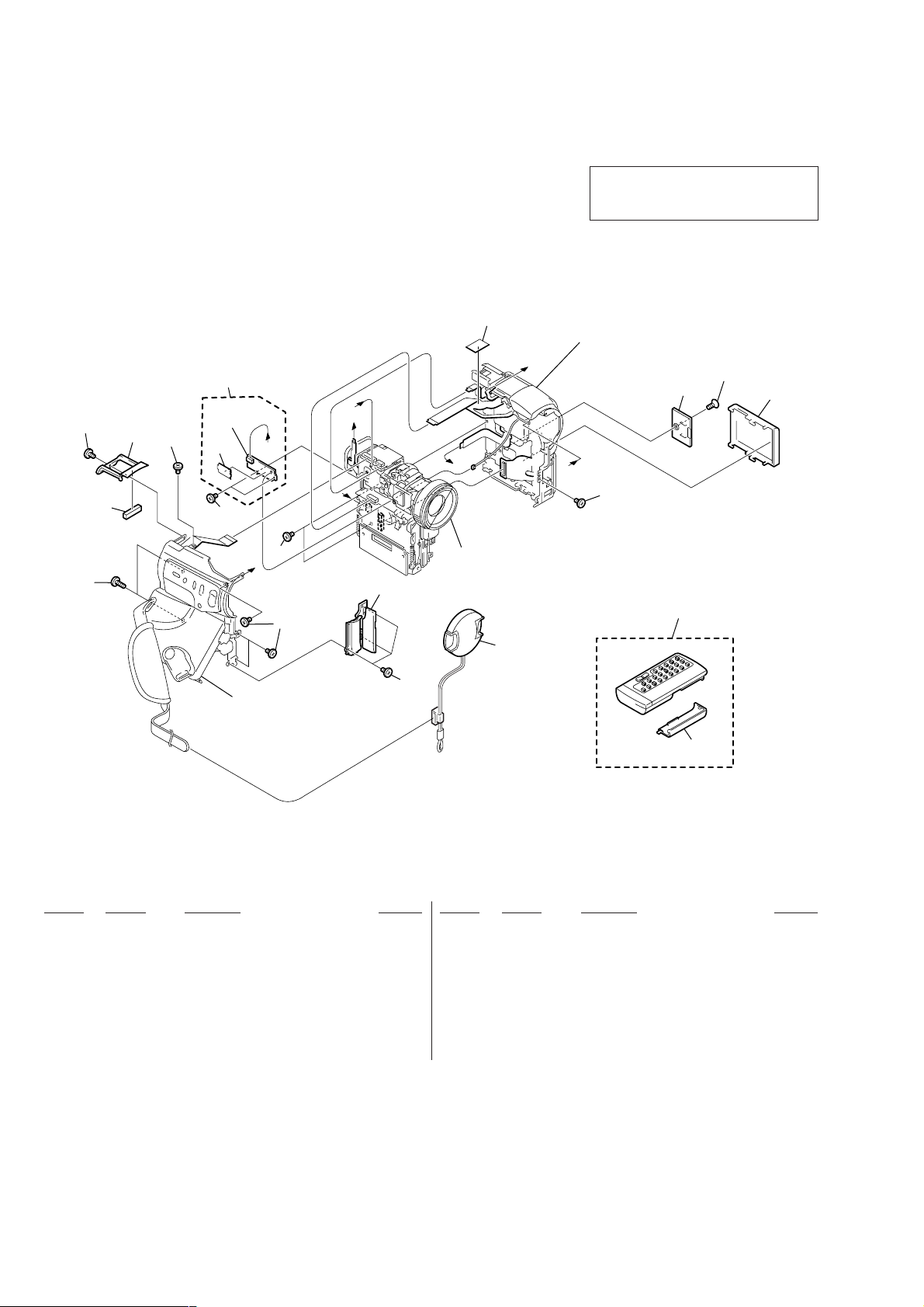
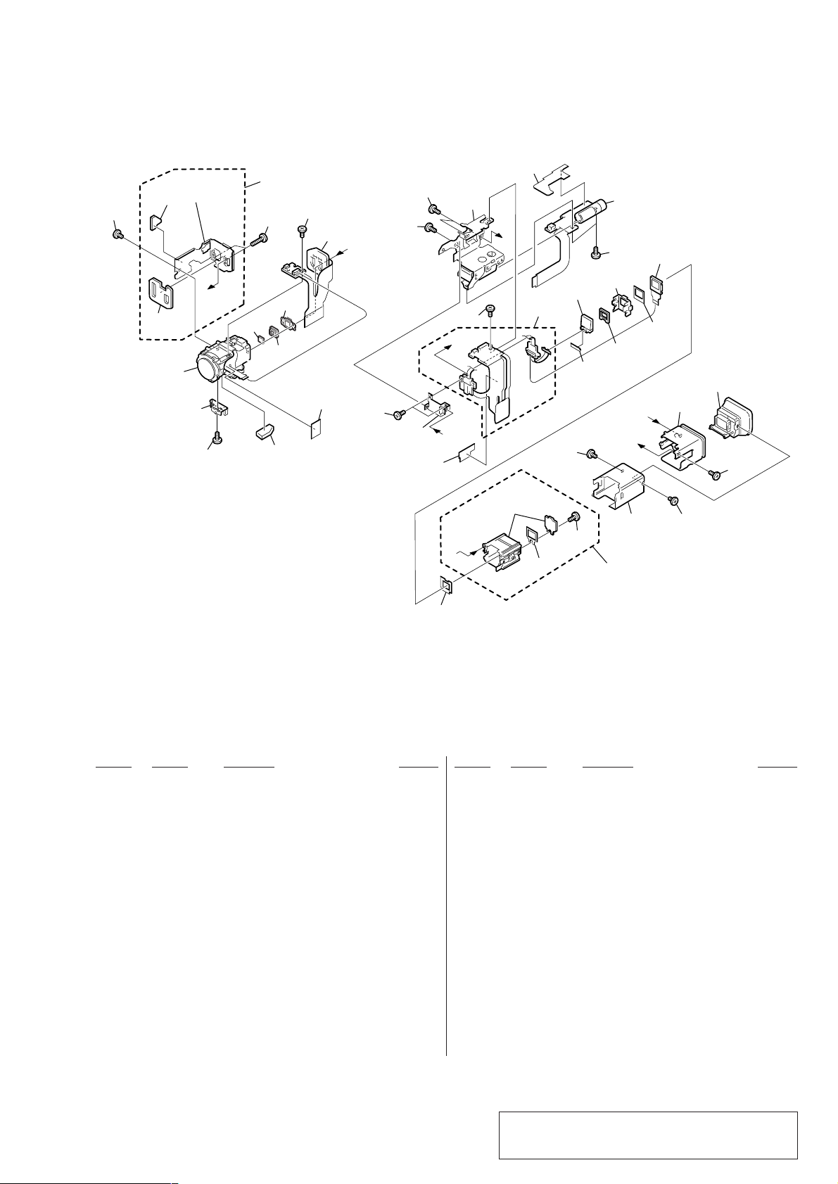
3-1-1. OVERALL SECTION
• The mechanical parts with no reference number
in the exploded views are not supplied.
The components identified by mark 0 or
dotted line with mark 0 are critical for safety.
Replace only with part number specified.
17
B
9
not
2
7
6
supplied
4
10
D
16
4
A
5
B
D
C
C
VTR overall section
(See page 24)
3
4
Cabinet (R) section-1, 2
(See page 26, 27)
A
4
11
14
12
13
1
2
Cabinet (L) section
(See page 23)
15
Ref. No. Part No. Description Remarks Ref. No. Part No. Description Remarks
1 X-3949-944-1 CAP ASSY, LENS
2 3-989-735-01 SCREW (M1.7), LOCK ACE, P2
3 X-3951-962-1 COVER ASSY, JACK ORNAMENTAL
4 4-974-725-01 SCREW (M1.7), LOCK ACE, P2
5 3-989-735-21 SCREW (M1.7), LOCK ACE, P2
6 3-070-446-01 CUSHION, ACOUSTIC ISOLATION
7 3-070-441-01 HS CABINET
9 not supplied BT-003 BOARD, COMPLETE (PC120E)
10 not supplied CASE ASSY, BT SHIELD (PC120E)
11 3-070-369-01 LID, CPC
* 12 3-057-437-01 LOCKACE (M1.7)
13 3-057-482-01 COVER, BATTERY
14 1-475-950-21 REMOTE COMMANDER (RMT-811)
15 3-053-056-01 LID, BATTERY CASE (FOR RMT-811)
16 3-389-523-16 SCREW (LOCK ACE) (PC120E)
* 17 3-064-657-01 GUARD, FK FLEXIBLE
— 22 —
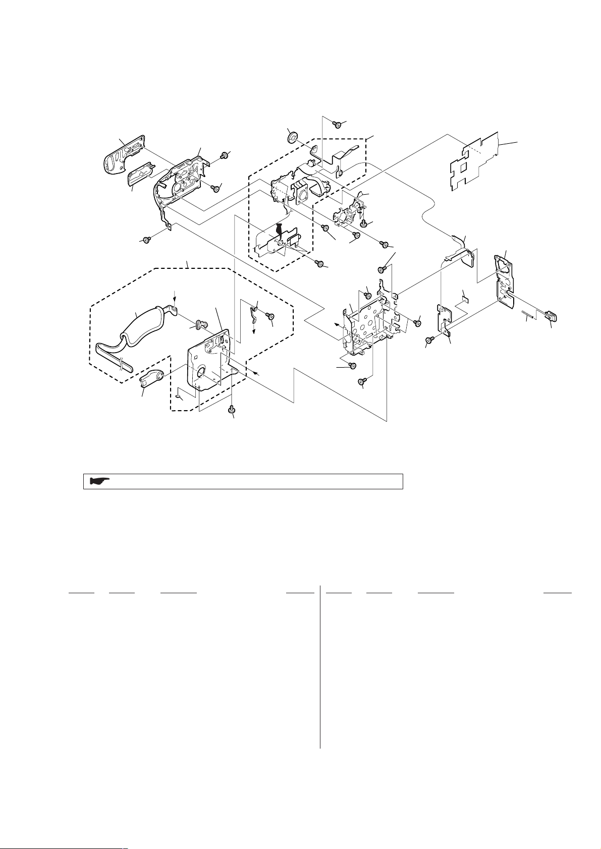
3-1-2. CABINET (L) SECTION
B
B
A
A
60
59
51
62
SP901
not
supplied
62
51
64
62
51
74
(Note)
62
62
62
72
65
66
69
70
71
75
51
73
62
55
54
53
52
51
57
58
51
63
51
61
: BT001 (Lithium battery) Control switch block (FK-1850) on the mount position.
The +P2 (0-No.) screws (M1.7 × 2.5) are MEC-processed. If the screws that are once removed,
are re-used, the screws may be loosened.
When re-assembling the mechanism, use the new +P2 (0-No.) screws (M1.7
×
2.5).
Note:
DCR-PC115E/PC120E
Ref. No. Part No. Description Remarks Ref. No. Part No. Description Remarks
51 4-974-725-01 SCREW (M1.7), LOCK ACE, P2
52 X-3951-891-1 GRIP ASSY, HOLD
53 3-969-387-01 FOOT, RUBBER
54 3-070-419-01 COVER (G), JACK
55 3-062-141-01 BELT, GRIP
57 3-070-416-01 BRACKET, BELT
58 X-3951-954-1 CABINET (G) ASSY
59 X-3951-901-2 COVER (L) ASSY, JACK
60 X-3951-956-1 PLATE (L) ASSY, ORNAMENTAL
61 3-070-404-21 CABINET (L)
62 3-914-366-01 SCREW (DIA. 1.7X4), PRECISION
63 1-476-871-11 SWITCH BLOCK, CONTROL (FK-1850)
64 X-3951-896-1 FRAME ASSY, JACK
65 3-070-467-01 SHEET (N), MUFFLE
66 X-3951-955-1 CABINET (REAR) ASSY (PC120E)
66 X-3951-958-1 CABINET (REAR) ASSY (PC115E)
69 3-062-128-01 SPRING, COMPRESSION
70 3-070-431-01 LOCK, BATTERY
71 1-476-870-11 SWITCH BLOCK, CONTROL (PS-1850)
72 not supplied KY-060 (N) BOARD, COMPLETE (PC120E)
72 not supplied KY-060 BOARD, COMPLETE (PC115E)
73 X-3951-889-1 FRAME ASSY, G
74 3-973-497-91 SCREW (M1.7), 0-NO. +P 2
75 3-071-508-01 SHEET (L)
SP901 1-529-857-11 SPEAKER (1.6 CM)
— 23 —
DCR-PC115E/PC120E
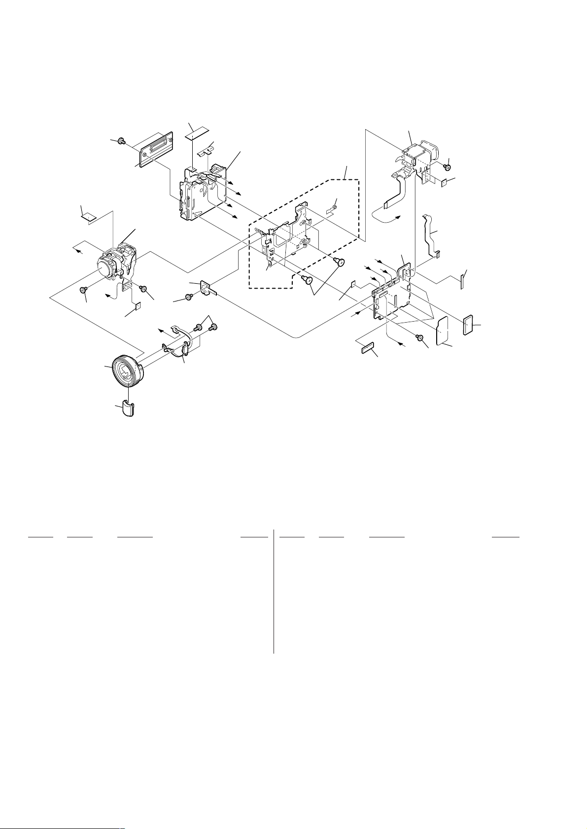
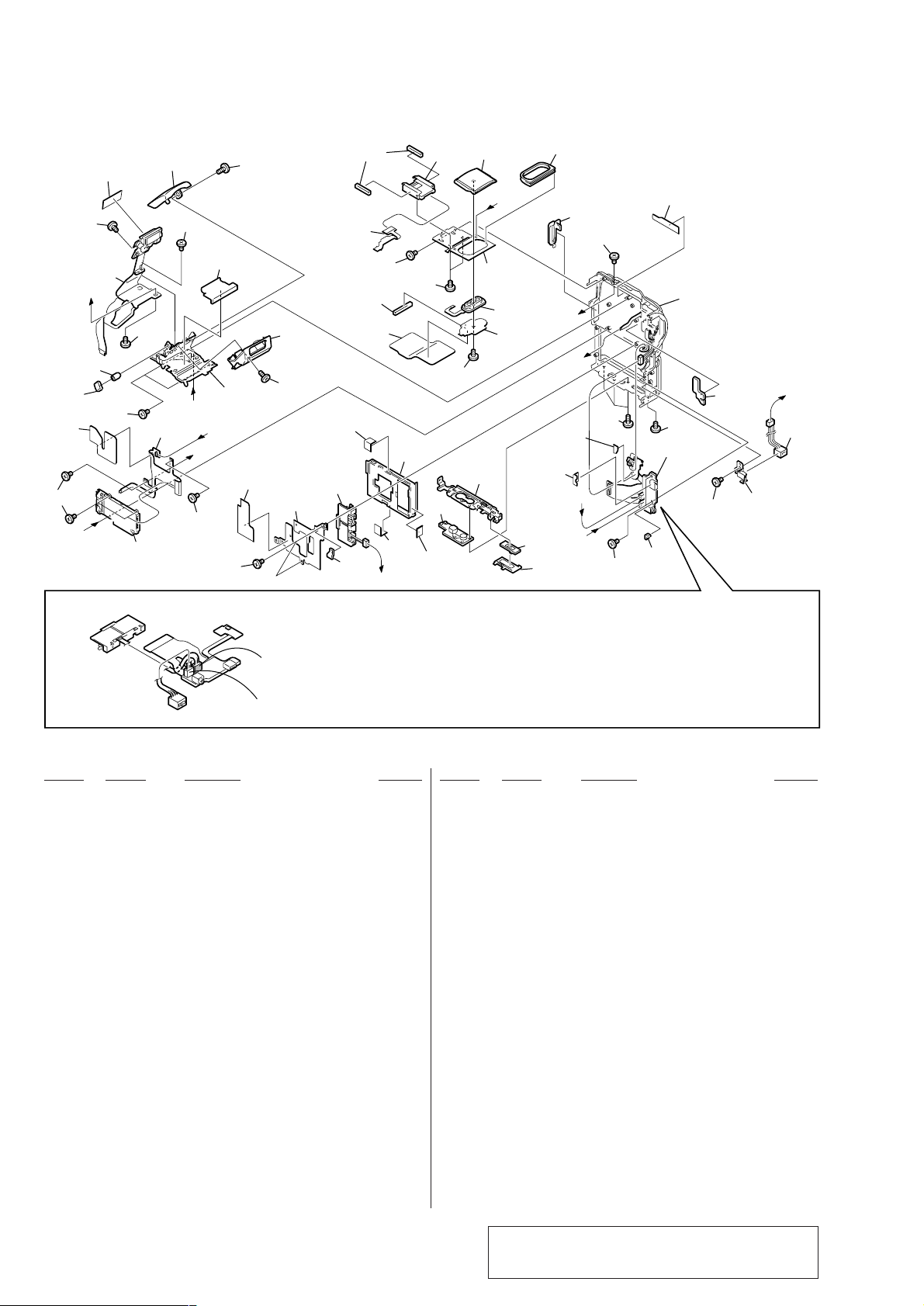
3-1-3. VTR OVERALL SECTION
117
105
A
105
102
B
108
LENS section
(See page 25)
not
supplied
105
A
not
supplied
106
103
104
109
Mechanism deck
C
E
F
D
not
supplied
111
110
not
supplied
116
G
E
C
F
EVF section
(See page 25)
G
113
D
118
B
105
105
112
not
supplied
115
not
supplied
114
101
Ref. No. Part No. Description Remarks Ref. No. Part No. Description Remarks
101 X-3951-884-1 WINDOW ASSY, IR
102 X-3951-885-1 BASE ASSY, MF
103 1-476-285-11 SWITCH BLOCK, CONTROL
104 3-914-366-01 SCREW (DIA. 1.7X4), PRECISION
105 4-974-725-01 SCREW (M1.7), LOCK ACE, P2
106 not supplied FP-386 BOARD, COMPLETE
108 3-059-722-01 COVER, CASSETTE COMPARTMENT
109 3-070-940-01 DF TAPE (2)
110 X-3951-883-1 FRAME ASSY, MD
111 3-059-718-01 SCREW (M1.4X1.5)
112 1-682-648-11 FP-384 FLEXIBLE BOARD (PC120E)
113 not supplied VC-270 (D) BOARD, COMPLETE (SERVICE)
(PC115E)
113 not supplied VC-270 (B) BOARD, COMPLETE (SERVICE)
(PC120E)
114 3-070-444-01 SHEET, IC RADIATION
115 3-070-456-01 SHEET, VC ELECTROSTATIC
116 3-070-967-01 MD CUSHION
* 117 3-064-657-01 GUARD, FK FLEXIBLE
118 3-072-242-01 CUSHION (B), VC
— 24 —
3-1-4. LENS-EVF SECTION
DCR-PC115E/PC120E
151
not
supplied
not
supplied
153
152
151
A
154
159
158
155
180
IC101
151
157
160
A
164
179
165
151
181
C
D
D
161
179
162
B
not
supplied
166
176
LED901
167
178
175
179
169
168
174
163
173
C
LCD902
170
B
171
172
179
178
177
Ref. No. Part No. Description Remarks Ref. No. Part No. Description Remarks
151 3-071-505-01 TAPPING (M1.7)
152 3-063-504-01 FRAME, LENS
153 not supplied DEVICE, LENS LSV-690B
154 not supplied FILTER BLOCK, OPTICAL
155 not supplied RUBBER (W), SEAL
157 not supplied CD-349P BOARD, COMPLETE
158 not supplied SCREW (B1.7), TAPPING
159 not supplied CASE ASSY, CD SHIELD
* 160 3-064-657-01 GUARD, FK FLEXIBLE
161 X-3951-895-1 FRAME ASSY, VF
162 3-070-462-01 SHEET, MC GUARD
0 163 not supplied FLASH UNIT (MC)
164 3-914-366-01 SCREW (DIA. 1.7X4), PRECISION
165 3-070-435-01 FRAME (B), VF
166 not supplied VM-027 BOARD, COMPLETE
169 3-070-437-01 BL UNIT
170 3-071-562-01 CUSHION (L) (2), BL
171 X-3951-894-1 LENS ASSY, VF
172 3-070-438-01 RING, VF REGULATION
173 X-3951-935-1 SLEEVE ASSY
174 X-3951-893-1 GUIDE ASSY, VF SLEEVE
175 3-713-791-51 SCREW (M1.7X3.5), TAPPING, P2
176 3-068-805-01 CUSHION, VF
* 177 3-062-767-01 CUSHION, LCD
178 3-989-735-01 SCREW (M1.7), LOCK ACE, P2
179 4-974-725-01 SCREW (M1.7), LOCK ACE, P2
180 3-070-966-01 GUIDE, BT CABLE
181 3-071-631-01 SHEET, VM GUARD
IC101 not supplied CCD BLOCK ASSY (CCD IMAGER)
LCD902 not supplied LCX033AN-1
167 3-069-940-01 SHEET METAL, BL RETAINER
168 3-062-205-11 CUSHION (B), BL
0 LED901 not supplied BLOCK (0.44), LIGHT GUIDE PLATE
Note : The components identified by mark 0 or dotted
— 25 —
line with mark 0 are critical for safety.
Replace only with part number specified.
DCR-PC115E/PC120E
3-1-5. CABINET (R) SECTION-1
not
supplied
237
213
A
242
243
207
211
207
F
Battery terminal
board
DC-IN connector
237
CN003
214
233
210
207
239
236
212
A
E
F
208
207
FJ-035 board
CN1334
(Blue)
CN1335 (White)
221
222
223
B
224
241
226
220
207
219
207
237
216
215
225
237
244
205
BT901
(Note)
206
209
D
Note:
CN1335 (for the DC-IN connector) and CN1334 (for the battery terminal board)of
FJ-035 board are the same size, and the number of the pins is the same.
So these connectors may be mistaken for each other. When these connectors
are mistaken, the charge system of the unit may break.
So ascertain the color of the connector when assembling these connectors.
244
204
not
supplied
MIC901
B
217
E
239
238
235
not
supplied
203
D
C
202
201
CN1334 (for the battery terminal board) ········ Blue
CN1335 (for the DC-IN connector) ················· White
207
207
231
(Note)
234
Cabinet (R) section-2
(See page 27)
228
207
C
J901
(Note)
230
Ref. No. Part No. Description Remarks Ref. No. Part No. Description Remarks
201 3-062-193-01 SLIDER, EJECT KNOB
202 3-062-192-01 KNOB, EJECT
203 X-3951-886-1 FRAME ASSY, BOTTOM
204 3-062-191-01 SCREW, TRIPOD
205 X-3951-933-1 HOLDER ASSY, BATTERY
206 3-070-368-01 RETAINER, BT TERMINAL
207 4-974-725-01 SCREW (M1.7), LOCK ACE, P2
208 3-071-466-01 SHEET, MS FLEXIBLE
209 3-072-241-01 CUSHION (A), VC
210 1-682-647-21 FP-383 FLEXIBLE BOARD
211 3-071-465-01 SHEET, BT CABLE
212 X-3951-882-1 STROBOSCOPE ASSY
0 213 not supplied STROBOSCOPE AF BLOCK ASSY (SERVICE)
214 3-070-391-01 ST CABINET UPPER
215 3-070-392-01 ST CABINET LOWER
216 3-070-446-01 CUSHION, ACOUSTIC ISOLATION
217 X-3951-900-1 PLATE ASSY, MICROPHONE RETAINER
219 3-070-394-01 FRAME, SHOE
220 1-682-649-11 FP-385 FLEXIBLE BOARD
221 3-070-818-01 CUSHION (S)
222 1-815-124-11 CONNECTOR, EXTERNAL (HOT SHOE)
223 X-3951-960-1 GRILLE ASSY, MICROPHONE (PC120E)
223 X-3951-961-1 GRILLE ASSY, MICROPHONE (PC115E)
224 3-070-381-01 INSULATOR, OUTER
225 3-071-068-01 SHEET, HS ACOUSTIC ISOLATION
226 3-070-348-01 BASE, PANEL LOCK
228 3-070-440-01 RUBBER (R), LENS
230 3-070-375-01 PLATE, DC RETAINER
231 not supplied FJ-035 (PN) BOARD, COMPLETE (PC120E)
231 not supplied FJ-035 (P) BOARD, COMPLETE (PC115E)
233 3-052-245-01 BOLT (M1.4)
234 3-071-241-01 CUSHION (L),LIGHT INTERCEPTION
235 3-071-467-01 CUSHION, FJ FLEXIBLE
236 3-070-393-01 PLATE, ORNAMENTAL
237 3-989-735-01 SCREW (M1.7), LOCK ACE, P2
238 3-989-735-31 SCREW (M1.7), LOCK ACE, P2
239 3-914-366-01 SCREW (DIA. 1.7X4), PRECISION
241 3-070-464-01 SHEET, (R) HEAT INSULATING
242 3-070-851-01 SCREW, HEXAGON HOLE PRECISION
243 3-072-320-01 CUSHION (A), STROBOSCOPE
244 4-920-257-01 COVER, FLEXIBLE INSULATING
BT901 1-694-796-11 TERMINAL BOARD, BATTERY
CN003 1-815-846-11 CONNECTOR, MEMORY STICK
J901 1-815-005-11 CONNECTOR, DC-IN
MIC901 1-476-282-21 MICROPHONE UNIT
— 26 —
Note : The components identified by mark 0 or dotted
line with mark 0 are critical for safety.
Replace only with part number specified.
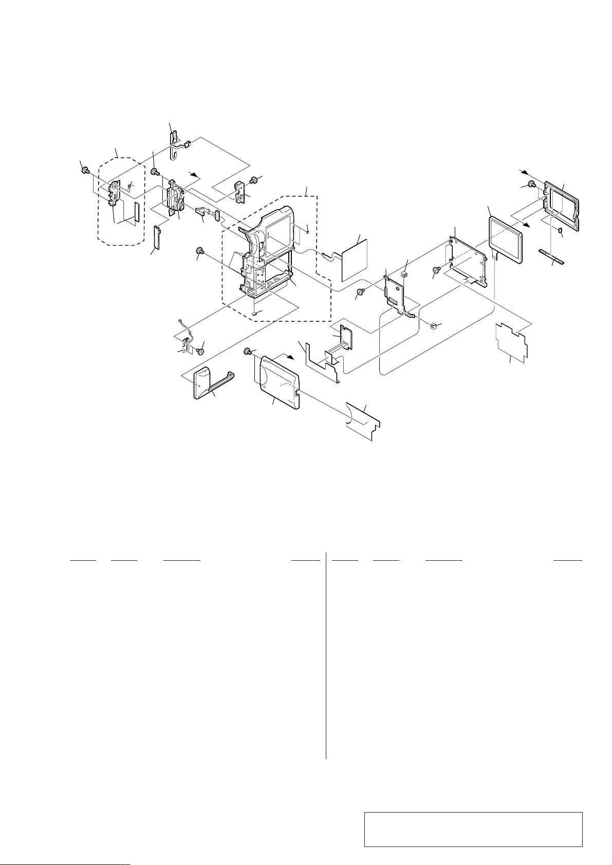
3-1-6. CABINET (R) SECTION-2
271
265
(Note)
273
274
272
B
DCR-PC115E/PC120E
Note:
The +P2 (0-No.) screws (M1.7 × 2.5) are MEC-processed. If the screws that are once removed,
are re-used, the screws may be loosened.
When re-assembling the mechanism, use the new +P2 (0-No.) screws (M1.7
265
(Note)
266
262
LCD901
A
276
×
2.5).
251
not
supplied
269
ANT901
270
268
267
252
260
264
252
259
263
not
supplied
258
A
257
252
261
275
256
PD-148B
255
252
ND901
255
254
B
not
supplied
253
Ref. No. Part No. Description Remarks Ref. No. Part No. Description Remarks
251 X-3951-879-1 CABINET (L) ASSY, LCD
252 4-974-725-01 SCREW (M1.7), LOCK ACE, P2
253 3-071-522-01 SHEET, PANEL DROP PROTECTION
254 3-060-704-01 SHEET (N), BL SHIELD
* 255 3-051-232-01 CLIP, PCB
256 not supplied PD-148B BOARD, COMPLETE
0 257 not supplied INVERTER TRANSFORMER UNIT
258 3-072-068-01 SHEET, PANEL INSULATING
259 X-3951-957-1 CABINET (R) ASSY, LCD (PC115E)
259 X-3952-018-1 CABINET (R) ASSY, LCD (PC120E)
260 3-070-367-11 COVER, BT ORNAMENTAL (PC115E)
260 X-3951-898-1 COVER ASSY, BT (PC120E)
261 1-476-867-21 SWITCH BLOCK, CONTROL (ME-1850)
262 X-3951-874-1 CABINET (R) ASSY
263 3-052-521-01 CUSHION (2), PANEL
264 3-969-387-01 FOOT, RUBBER
— 27 —
265 3-973-497-91 SCREW (M1.7), 0-NO. +P 2
266 3-070-377-01 COVER (LOWER), HINGE
267 1-961-286-11 HARNESS (PT-128)
268 3-914-366-01 SCREW (DIA. 1.7X4), PRECISION
269 3-070-376-01 COVER (UPPER), HINGE
270 X-3951-876-1 HINGE ASSY
271 1-682-651-21 FP-387 FLEXIBLE BOARD
272 3-989-735-31 SCREW (M1.7), LOCK ACE, P2
273 X-3951-878-1 PLATE ASSY, BLIND
* 274 3-055-323-01 SPRING (MK), TORSION
275 3-070-465-01 SHEET, PANEL HEAT INSULATING
276 4-223-676-09 SCREW (M1.7), MI
ANT901 1-754-210-21 ANTENNA (2.4GHz) (PC120E)
LCD901 not supplied ACX311AKB-1
0 ND901 not supplied TUBE, FLUORESCENT, COLD CATHODE
Note : The components identified by mark 0 or dotted
line with mark 0 are critical for safety.
Replace only with part number specified.
 Loading...