

SONY DCR-HC40 Service Manual
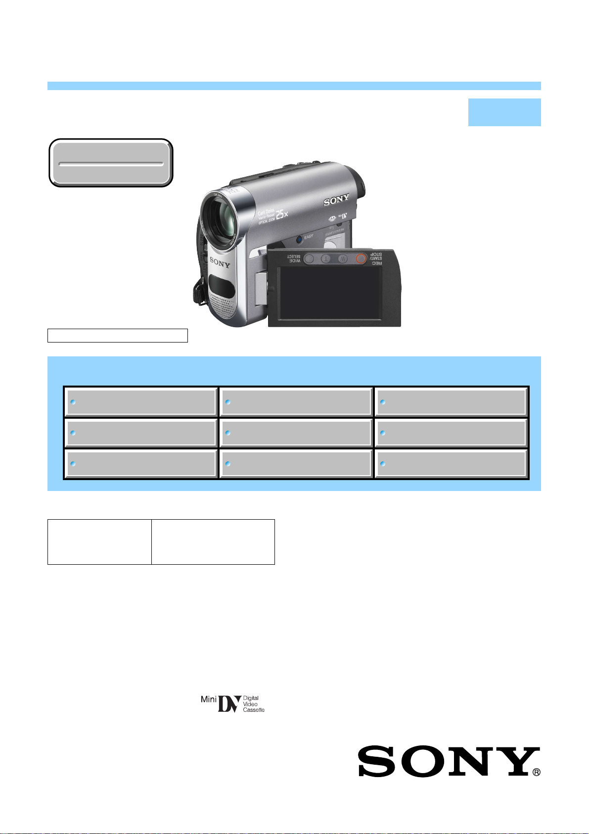
DCR-HC62/HC62E
RMT-831
SERVICE MANUAL
Ver. 1.1 2008.04
Revision History
Revision History
N MECHANISM (MDX-N220)
Link
Link
SPECIFICATIONS
Photo: DCR-HC62
DISASSEMBLY
LEVEL 2
US Model
Canadian Model
AEP Model
UK Model
East European Model
North European Model
E Model
Argentine Model
Korea Model
Tourist Model
Japanese Model
SCHEMATIC DIAGRAMS
MODEL INFORMATION TABLE
SERVICE NOTE
• Precaution on Replacing the VC-525 Board
The components identified by
mark 0 or dotted line with
mark 0 are critical for safety.
Replace only with part number specified.
Les composants identifiés par une
marque 0 sont critiques pour la
sécurité.
Ne les remplacer que par une pièce
portant le numéro spécifié.
BLOCK DIAGRAMS
FRAME SCHEMATIC DIAGRAM
PRINTED WIRING BOARDS
REPAIR PARTS LIST
DIGITAL VIDEO CAMERA RECORDER
DCR-HC62/HC62E_L2
Sony EMCS Co.
2008D0800-1
© 2008.04
Published by Kohda TEC9-852-235-31
These specifications are extracted from instruction
g
manual of DCR-HC62E.
SPECIFICATIONS
ENGLISH JAPANESE
ENGLISH JAPANESE
System
Video recording system
2 rotary heads, Helical scanning system
Still image recording system
Exif Ver. 2.2*
Audio recording system
Rotary heads, PCM system
Quantization: 12 bits (Fs 32 kHz, stereo
1, stereo 2), 16 bits (Fs 48 kHz, stereo)
Video signal
PAL color, CCIR standards
Usable cassette
Mini DV cassette with the mark
printed
Tape speed
SP: Approx. 18.81 mm/s
LP: Approx. 12.56 mm/s
Recording/playback time
SP: 60 min (using a DVM60 cassette)
LP: 90 min (using a DVM60 cassette)
Fast forward/rewind time
Approx. 2 min 40 s (using a DVM60
cassette and rechargeable battery pack)
Approx. 1 min 45 s (using a DVM60
cassette and AC Adaptor)
Viewfinder
Electric viewfinder (0.27 type, aspect
ratio 16:9, 123 200 dots)
Image device
3 mm (1/6 type) CCD (Charge Coupled
Device)
Gross: Approx. 1 070 000 pixels
Effective (still): 1 000 000 pixels
Effective (movie): 690 000 pixels
Lens
Carl Zeiss Vario-Tessar
×
(Optical), 2 000 × (Digital)
25
Focal length
f=2.5 ~ 62.5 mm (1/8 ~ 2 1/2 in.)
When converted to a 35 mm still
camera
In CAMERA-TAPE:
41 ~ 1 189 mm (1 5/8 ~ 46 7/8 in.)
(16:9)
43 ~ 1 075 mm (1 3/4 ~ 42 3/8 in.) (4:3)
In CAMERA-MEMORY:
36 ~ 900 mm (1 7/16 ~ 35 1/2 in.) (4:3)
39 ~ 975 mm (1 9/16 ~ 38 1/2 in.) (16:9)
F1.8 ~ 3.2
Filter diameter: 30 mm (1 3/16 in.)
Color temperature
[AUTO], [ONE PUSH], [INDOOR]
(3 200 K), [OUTDOOR] (5 800 K)
Minimum illumination
8 lx (lux) (AUTOSLW SHTR ON,
Shutter speed 1/25 s)
0 lx (lux) (during NightShot plus
function)
*“Exif” is a file format for still images,
established by the JEITA (Japan
Electronics and Information Technology
Industries Association). Files in this
format can have additional information
such as your camcorder’s setting
information at the time of recordin
Input/Output connectors
A/V Remote Connector
10-pin connector
Video signal: 1 Vp-p, 75
Luminance signal: 1 Vp-p, 75
Chrominance signal: 0.3 Vp-p, 75
(ohms)
Audio signal: 327 mV (at load
impedance 47 k
impedance with less than 2.2 k
(kilohms)
USB jack
mini-B
DV input/output jack
i.LINK Interface (IEEE1394, 4-pin
connector S100)
Ω
(ohms)
Ω
(ohms)
Ω
(kilohms)), Output
Ω
Ω
LCD screen
Picture
6.7 cm (2.7 type, aspect ratio 16:9)
Total dot number
123 200 (560
×
220)
General
Power requirements
DC 6.8 V/7.2 V (battery pack)
DC 8.4 V (AC Adaptor)
Average power consumption
During camera recording using the
viewfinder 2.5 W
During camera recording using the
LCD 2.8 W
Operating temperature
0 ˚C to 40 ˚ C (32 ˚F to 104 ˚F)
Storage temperature
-20 ˚C to + 60 ˚ C (-4 ˚F to + 140 ˚ F)
Dimensions (approx.)
×
85 × 114 mm
63
(2 1/2
×
33/8 × 4 1/2 in.) (w/h/d)
including the projecting parts
×
85 × 115 mm
63
×
33/8 × 4 5/8 in.) (w/h/d)
(2 1/2
including the projecting parts with
supplied battery pack NP-FH40
attached
Mass (approx.)
390g(13oz) main unit only,
455g(1lb) including the NP-FH40
rechargeable battery pack and DVM60
cassette
.
Supplied accessories
AC Adapt or (1)
Power c ord (Mains lead) (1 )
Wireless Remote Commande r (1)
A/V connec ting c able (1)
USB cable (1)
Rec harge able ba ttery pa ck NP-FH40 (1)
CD-ROM “Handycam Application
Software” (1)
Operating Gu ide (1)
AC Adaptor AC-L200/L200B
Power requirements
AC 100 V - 240 V, 50/60 Hz
Current consumption
0.35 - 0.18 A
Power consumption
18 W
Output voltage
DC 8.4 V*
Operating temperature
0 ˚C to 40 ˚ C (32 ˚F to 104 ˚F)
Storage temperature
-20 ˚C to + 60 ˚ C (-4 ˚F to + 140 ˚ F)
Dimensions (approx.)
×
29 × 81 mm
48
×
13/16 × 3 1/4 in.) (w/h/d)
(1 15/16
excluding the projecting parts
Mass (approx.)
170 g (6.0 oz) exc luding the power cord
(mains lead)
See the label on the AC Adaptor for
*
other specifications.
Rechargeable battery pack NP-FH40
Maximum output voltage
DC 8.4 V
Output voltage
DC 7.2 V
Capacity
4.9 Wh (680 mAh)
Dimensions (approx.)
×
18.5 × 45.0 mm
31.8
×
3/4 × 1 13/16 in.) (w/h/d)
(1 5/16
Mass (approx.)
45 g (1.6 oz)
Operating temperature
0 ˚C to 40 ˚C (32 ˚ F to 104 ˚F)
Type
Lithium ion
Design and specifications are subject to change
without notice.
DCR-HC62/HC62E_L2
— 2 —

These specifications are extracted from instruction
manual of DCR-HC62.
SPECIFICATIONS
ENGLISH JAPANESE
ENGLISH JAPANESE
System
Video recording system
2 rotary heads, Helical scanning system
Still image recording system
Exif Ver. 2.2*
Audio recording system
Rotary heads, PCM system
Quantization: 12 bits (Fs 32 kHz, stereo
1, stereo 2), 16 bits (Fs 48 kHz, stereo)
Video signal
NTSC color, EIA standards
Usable cassette
Mini DV cassette with the mark
printed
Tape speed
SP: Approx. 18.81 mm/s
LP: Approx. 12.56 mm/s
Recording/playback time
SP: 60 min (using a DVM60 cassette)
LP: 90 min (using a DVM60 cassette)
Fast forward/rewind time
Approx. 2 min 40 s (using a DVM60
cassette and rechargeable battery pack)
Approx. 1 min 45 s (using a DVM60
cassette and AC Adaptor)
Viewfinder
Electric viewfinder (0.27 type, aspect
ratio 16:9, 123 200 dots)
Image device
3 mm (1/6 type) CCD (Charge Coupled
Device)
Gross: Approx. 1 070 000 pixels
Effective (still): 1 000 000 pixels
Effective (movie): 690 000 pixels
Lens
Carl Zeiss Vario-Tessar
×
(Optical), 2 000 × (Digital)
25
Focal length
f=2.5 ~ 62.5 mm (1/8 ~ 2 1/2 in.)
When converted to a 35 mm still
camera
In CAMERA-TAPE:
41 ~ 1 189 mm (1 5/8 ~ 46 7/8 in.)
(16:9)
43 ~ 1 075 mm (1 3/4 ~ 42 3/8 in.) (4:3)
In CAMERA-MEMORY:
36 ~ 900 mm (1 7/16 ~ 35 1/2 in.) (4:3)
39 ~ 975 mm (1 9/16 ~ 38 1/2 in.) (16:9)
F1.8 ~ 3.2
Filter diameter: 30 mm (1 3/16 in.)
Color temperature
[AUTO], [ONE PUSH], [INDOOR]
(3 200 K), [OUTDOOR] (5 800 K)
Minimum illumination
8 lx (lux) (AUTOSLW SHTR ON,
Shutter speed 1/30 s)
0 lx (lux) (during NightShot plus
function)
*
“Exif” is a file format for still images,
established by the JEITA (Japan
Electronics and Information Technology
Industries Association). Files in this
format can have additional information
such as your camcorder’s setting
information at the time of recording.
Input/Output connectors
A/V Remote Connector
10-pin connector
Video signal: 1 Vp-p, 75
Luminance signal: 1 Vp-p, 75
Chrominance signal: 0.286 Vp-p, 75
(ohms)
Audio signal: 327 mV (at load
impedance 47 k
impedance with less than 2.2 k
(kilohms)
USB jack
mini-B
DV input/output jack
i.LINK Interface (IEEE1394, 4-pin
connector S100)
Ω
(ohms)
Ω
(ohms)
Ω
(kilohms)), Output
LCD screen
Picture
6.7 cm (2.7 type, aspect ratio 16:9)
Total dot number
123 200 (560
×
220)
General
Power requirements
DC 6.8 V/7.2 V (battery pack)
DC 8.4 V (AC Adaptor)
Average power consumption
During camera recording using the
viewfinder 2.5 W
During camera recording using the
LCD 2.8 W
Operating temperature
0 ˚C to 40 ˚ C (32 ˚F to 104 ˚F)
Storage temperature
-20 ˚C to + 60 ˚C (-4 ˚ F to + 140 ˚F)
Dimensions (approx.)
63
×
85 × 114 mm
(2 1/2
×
33/8 × 4 1/2 in.) (w/h/d)
including the projecting parts
63
×
85 × 115 mm
(2 1/2
×
33/8 × 4 5/8 in.) (w/h/d)
including the projecting parts with
supplied battery pack NP-FH40
attached
Mass (approx.)
390g(13oz) main unit only,
455g(1lb) including the NP-FH40
rechargeable battery pack and DVM60
cassette
Supplied accessories
AC Adapt or (1)
Power c ord (Mains lead) (1 )
Wireless Remote Commande r (1)
A/V connec ting c able (1)
USB cable (1)
Rec harge able ba ttery pa ck NP-FH40 (1)
CD-ROM “Handycam Application
Software” (1)
Operating Gu ide (1)
AC Adaptor AC-L200/L200B
Power requirements
AC 100 V - 240 V, 50/60 Hz
Current consumption
0.35 - 0.18 A
Ω
Ω
Power consumption
18 W
Output voltage
DC 8.4 V*
Operating temperature
0 ˚C to 40 ˚C (32 ˚F to 104 ˚F)
Storage temperature
-20 ˚C to + 60 ˚C (-4 ˚ F to + 140 ˚F)
Dimensions (approx.)
48
×
29 × 81 mm
(1 15/16
×
excluding the projecting parts
Mass (approx.)
170 g (6.0 oz) exc luding the power cord
(mains lead)
*
13/16 × 3 1/4 in.) (w/h/d)
See the label on the AC Adaptor for
other specifications.
Rechargeable battery pack NP-FH40
Maximum output voltage
DC 8.4 V
Output voltage
DC 7.2 V
Capacity
4.9 Wh (680 mAh)
Dimensions (approx.)
×
18.5 × 45.0 mm
31.8
(1 5/16
×
Mass (approx.)
Operating temperature
Type
Design and specifications are subject to change
without notice.
3/4 × 1 13/16 in.) (w/h/d)
45 g (1.6 oz)
0 ˚C to 40 ˚C (32 ˚F to 104 ˚F)
Lithium ion
DCR-HC62/HC62E_L2
— 3 —

概略仕様
ENGLISH JAPANESE
ENGLISH JAPANESE
システム
録画方式
ヘッドヘリカルスキャン
回転
2
静止画記録方式
Exif Ver.2.2*
録音方式
回転
ヘッド
2
ビット
12
ビット
16
映像信号
NTSC
使用可能カセット
テープ速度
SP:約18 .81mm/
LP:約12.5 6mm/
録画/再生時間
SP:60分(DVM60
LP:90
早送り、巻き戻し時間
バッテリー使用時:
約
2分40秒(DVM 60
アダプター使用時:
AC
約
1分45秒(DVM60
ファインダー
電子ファインダー(
16: 9、123 20 0
撮像素子
3.0m m(1/6型)CCD
総画素数:約
静止画時有効画素数 :約
動画時有効画素数 :約
ズームレンズ
カールツァイス バリオテッサー
倍(光学)、
25
2.5
f=
35mm
「
CAMERA-TAPE
41〜1189mm(16: 9
(
4:3
「
CAMERA-MEMORY
36〜900mm(4:3
(
16:9
F1. 8〜3.2
フィルター径
色温度切り換え
[オート]、[ワンプッシュ]、
[屋内](
[屋外](
最低被写体照度
(ルクス)(オートスロ ーシャッター入、
8l x
シャッタースピード
(ルクス)(
0lx
*
(社)電子情報技術産業協会(
れた、撮影情報などの付帯情報を追加すること
ができる静止画用のファイルフォーマット。
(ステレオ1、ステレオ2)
32kHz
(ステレオ)
48kHz
カラー、
マークの ついたミニ
〜
モードでは43〜
モードでは39〜
標準方式
EI A
秒
秒
(
分
DVM60
0.27
ドット)
万画素
107
2000
.5mm
62
カメラ換算では
」時:
使用時)
使用時)
使用時)
使用時)
倍(デジタル)
1075mm
モード)
30mm
)、
3200K
)
5800K
1/30
NightShot plus
カセット
DV
型、アスペクト比
固体撮像素子
万画素
100
万画素
69
モード)
)
」時:
mm)
97 5
秒)
時)
)にて制定さ
JEITA
入出力端子
リモート端子
A/V
ピン特殊コネクター
10
映像:
出力
Y
出力
C
音声:
327m V(47k
ダンス
端子
USB
mini-B
端子
DV
i.LINK(IEEE1394 4
1Vp-p、75
1Vp-p、75
0.286Vp-p、75
Ω以下
2.2k
Ω
Ω
Ω
Ω負荷時)、出力インピー
ピンコネクター
液晶画面
画面サイズ
6.7cm(2.7
総ドット数
123 200
横
型、アスペクト比
ドット
56 0×縦22 0
電源部、その他
電源電圧
バッテリー端子入力
端子入力
DC
消費電力
2.5W
2.8W
動作温度
0℃〜+4 0
保存温度
−
外形寸法
63×85×114mm
(突起部含む)
63×85×115mm
(突起部含む、付属バッテリーパック
FH40
本体質量
約
撮影時総質量
約
(
DVM60
付属品
ACアダプター(1 )
電源コード(1 )
ワイヤレスリモコン(1 )
A/ V接続ケーブル(1)
USBケーブル(1 )
リチャージャブルバッテリーパック
NP-FH4 0 (1 )
CD-ROM「Han d yc a mApplication
Soft ware 」(1 )
取扱説明書
8.4 V
(ファインダー使用時、明るさ標準)
(液晶画面使用時、明るさ標準)
℃
20℃〜+6 0
390g
455g
℃
装着状態)
(本体のみ)
(バッテリー
)含む。)
.2V
6.8V/7
(幅×高さ×奥行き)
(幅×高さ×奥行き)
NP-FH40
16: 9
、テープ
)
S100
NP-
アダプター
AC
電源
AC100V〜240 V、50/6 0Hz
消費電力
18W
定格出力
DC8.
動作温度
0℃〜+4 0
保存温度
−
)
20℃〜+6 0
外形寸法
約
48×29×81mm
(幅×高さ×奥行き)
質量
約
170g
その他の仕様についてはACアダプターのラ
*
ベルをご覧ください。
リチャージャブルバッテリーパック
NP-FH4 0
最大電圧
DC8 .4 V
公称電圧
DC7 .2 V
容量
4.9Wh(680mAh
最大外形寸法
約
31 .8×18.5×45.0 mm
(幅×高さ×奥行き)
質量
約
45 g
使用温度
0℃〜+4 0
使用電池
Li-ion
本機の仕様および外観は、改良のため予告なく変
更することがありますが、ご了承ください。
AC-L200/L200B
4V *
℃
℃
(最大突起部をのぞく)
(本体のみ)
)
℃
DCR-HC62/HC62E_L2
— 4 —

Model information table
Model
Destination
Color system
• Abbreviation
AR : Argentine model
CND : Canadian model
EE : East European model
J : Japanese model
JE : Tourist model
KR : Korea model
NE : North European model
HC62
US, CND, AR,
KR, E, J
NTSC
HC62E
AEP, UK, E,
NE, EE, JE
PA L
DCR-HC62/HC62E_L2
— 5 —

ENGLISH JAPANESE
ENGLISH JAPANESE
Danger of explosion if battery is incorrectly replaced.
CAUTION
Replace only with the same or equivalent type.
SAFETY-RELATED COMPONENT WARNING!!
COMPONENTS IDENTIFIED BY MARK 0 OR DOTTED LINE WITH
MARK 0 ON THE SCHEMATIC DIAGRAMS AND IN THE PARTS
LIST ARE CRITICAL TO SAFE OPERATION. REPLACE THESE
COMPONENTS WITH SONY PARTS WHOSE PART NUMBERS
APPEAR AS SHOWN IN THIS MANUAL OR IN SUPPLEMENTS
PUBLISHED BY SONY.
SAFETY CHECK-OUT
After correcting the original service problem, perform the following
safety checks before releasing the set to the customer.
1. Check the area of your repair for unsoldered or poorly-soldered
connections. Check the entire board surface for solder splashes
and bridges.
2. Check the interboard wiring to ensure that no wires are
"pinched" or contact high-wattage resistors.
3. Look for unauthorized replacement parts, particularly
transistors, that were installed during a previous repair. Point
them out to the customer and recommend their replacement.
4. Look for parts which, through functioning, show obvious signs
of deterioration. Point them out to the customer and
recommend their replacement.
5. Check the B+ voltage to see it is at the values specified.
6. Flexible Circuit Board Repairing
•Keep the temperature of the soldering iron around 270˚C
during repairing.
• Do not touch the soldering iron on the same conductor of the
circuit board (within 3 times).
• Be careful not to apply force on the conductor when soldering
or unsoldering.
ATTENTION AU COMPOSANT AYANT RAPPORT
À LA SÉCURITÉ!
LES COMPOSANTS IDENTIFÉS PAR UNE MARQUE 0 SUR LES
DIAGRAMMES SCHÉMATIQUES ET LA LISTE DES PIÈCES SONT
CRITIQUES POUR LA SÉCURITÉ DE FONCTIONNEMENT. NE
REMPLACER CES COMPOSANTS QUE PAR DES PIÈSES SONY
DONT LES NUMÉROS SONT DONNÉS DANS CE MANUEL OU
DANS LES SUPPÉMENTS PUBLIÉS PAR SONY.
Unleaded solder
Boards requiring use of unleaded solder are printed with the leadfree mark (LF) indicating the solder contains no lead.
(Caution: Some printed circuit boards may not come printed with
the lead free mark due to their particular size.)
: LEAD FREE MARK
Unleaded solder has the following characteristics.
• Unleaded solder melts at a temperature about 40°C higher than
ordinary solder.
Ordinary soldering irons can be used but the iron tip has to be
applied to the solder joint for a slightly longer time.
Soldering irons using a temperature regulator should be set to
about 350°C.
Caution: The printed pattern (copper foil) may peel away if the
heated tip is applied for too long, so be careful!
• Strong viscosity
Unleaded solder is more viscous (sticky, less prone to flow) than
ordinary solder so use caution not to let solder bridges occur such
as on IC pins, etc.
•Usable with ordinary solder
It is best to use only unleaded solder but unleaded solder may
also be added to ordinary solder.
DCR-HC62/HC62E_L2
— 6 —
ENGLISH JAPANESE
ENGLISH JAPANESE
電池の交換は,正しく行わないと破裂する恐れがあり
注意
ます。電池を交換する場合には必ず同じ型名の電池
又は同等品と交換してください。
サービス,点検時には次のことにご注意下さい。
1. 注意事項をお守りください。
サービスのとき特に注意を要する個所については,
キャビネット,シャーシ,部品などにラベルや捺印で
注意事項を表示しています。これらの注意書き及び取
扱説明書等の注意事項を必ずお守り下さい。
2. 指定部品のご使用を
セットの部品は難燃性や耐電圧など安全上の特性を
持ったものとなっています。従って交換部品は,使用
されていたものと同じ特性の部品を使用して下さい。
特に回路図,部品表に0印で指定されている安全上重要
な部品は必ず指定のものをご使用下さい。
3. 部品の取付けや配線の引きまわしはもとどおりに
安全上,チューブやテープなどの絶縁材料を使用した
り,プリント基板から浮かして取付けた部品がありま
す。また内部配線は引きまわしやクランパによって発
熱部品や高圧部品に接近しないよう配慮されています
ので,これらは必ずもとどおりにして下さい。
4. サービス後は安全点検を
サービスのために取外したネジ,部品,配線がもとど
おりになっているか,またサービスした個所の周辺を
劣化させてしまったところがないかなどを点検し,安
全性が確保されていることを確認して下さい。
5. チップ部品交換時の注意
• 取外した部品は再使用しないで下さい。
• タンタルコンデンサのマイナス側は熱に弱いため交
換時は注意して下さい。
6. フレキシブルプリント基板の取扱いについて
• コテ先温度を270℃前後にして行なって下さい。
• 同一パターンに何度もコテ先を当てないで下さい。
(3回以内)
• パターンに力が加わらないよう注意して下さい。
7. 無鉛半田について
無鉛半田を使用している基板には,無鉛(LeadFree)を意
味するレッドフリーマークがプリントされています。
(注意:基板サイズによっては,無鉛半田を使用して
いてもレッドフリーマークがプリントされて
いないものがあります)
:レッドフリーマーク
無鉛半田には,以下の特性があります。
• 融点が従来の半田よりも約40℃高い。
従来の半田こてをそのまま使用することは可能です
が,少し長めにこてを当てる必要があります。
温度調節機能のついた半田こてを使用する場合,約
350℃に設定して下さい。
注意: 半田こてを長く当てすぎると,基板のパター
ン(銅箔)がはがれてしまうことがあります
ので,注意して下さい。
• 粘性が強い
従来の半田よりも粘性が強いため,IC端子などが半田
ブリッジしないように注意して下さい。
• 従来の半田と混ぜて使用可能
無鉛半田には無鉛半田を追加するのが最適ですが,
従来の半田を追加しても構いません。
DCR-HC62/HC62E_L2
— 7 —
ENGLISH JAPANESE
y
1. SERVICE NOTE
ENGLISH JAPANESE
1-1. POWER SUPPLY DURING REPAIRS
In this unit, about 10 seconds after power is supplied to the battery terminal using the regulated power supply (8.4V), the power is shut off so
that the unit cannot operate.
These following method is available to prevent this.
Method:
Use the AC power adaptor (AC-L200/L200B).
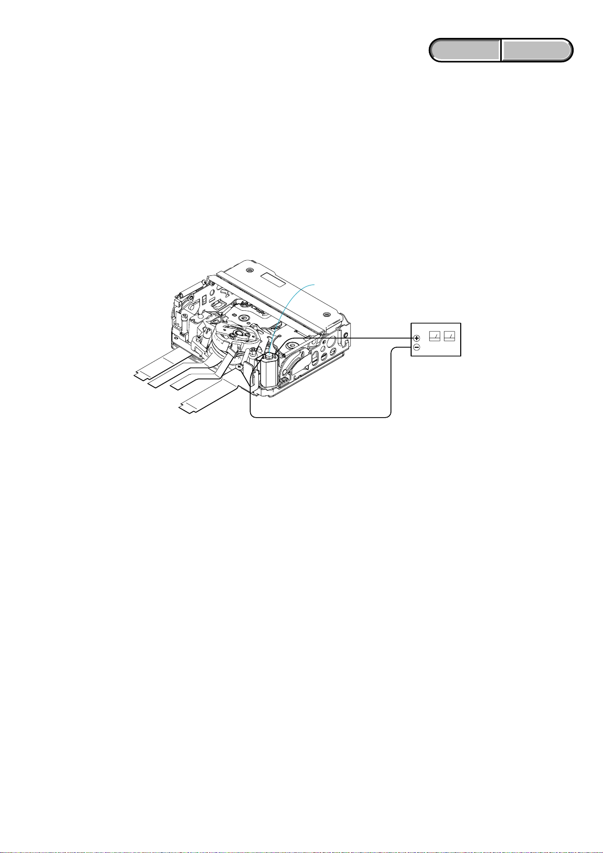
1-2. TO TAKE OUT A CASSETTE WHEN NOT EJECT (FORCE EJECT)
1 Refer to “2. DISASSEMBLY” to remove the mechanism deck block.
2 Supply +4.5V from the DC power supply to the loading motor and unload with a pressing the cassette compartment.
Loading motor
DC power suppl
(+ 4.5Vdc)
1-3. SETTING THE “FORCED POWER ON” MODE
It is possible to turn on power by adjustment remote commander (RM-95 or NEW LANC JIG).
Operate the VTR function using the adjustment remote commander.
1-3-1. Setting the “Forced Camera Power ON” Mode
1) Select page: 0, address: 01, and set data:01.
2) Select page: A, address: 10, set data:01 and press the “PAUSE (Write) ” button of the adjustment remote commander.
1-3-2. Setting the “Forced VTR Power ON” Mode
1) Select page: 0, address: 01, and set data:01.
2) Select page: A, address: 10, set data:02 and press the “PAUSE (Write) ” button of the adjustment remote commander.
1-3-3. Exiting the “Forced Power ON” Mode
1) Select page: 0, address: 01, and set data:01.
2) Select page: A, address: 10, set data:00 and press the “PAUSE (Write) ” button of the adjustment remote commander.
3) Select page: 0, address: 01, and set data: 00.
DCR-HC62/HC62E_L2
1-1
ENGLISH JAPANESE
ENGLISH JAPANESE
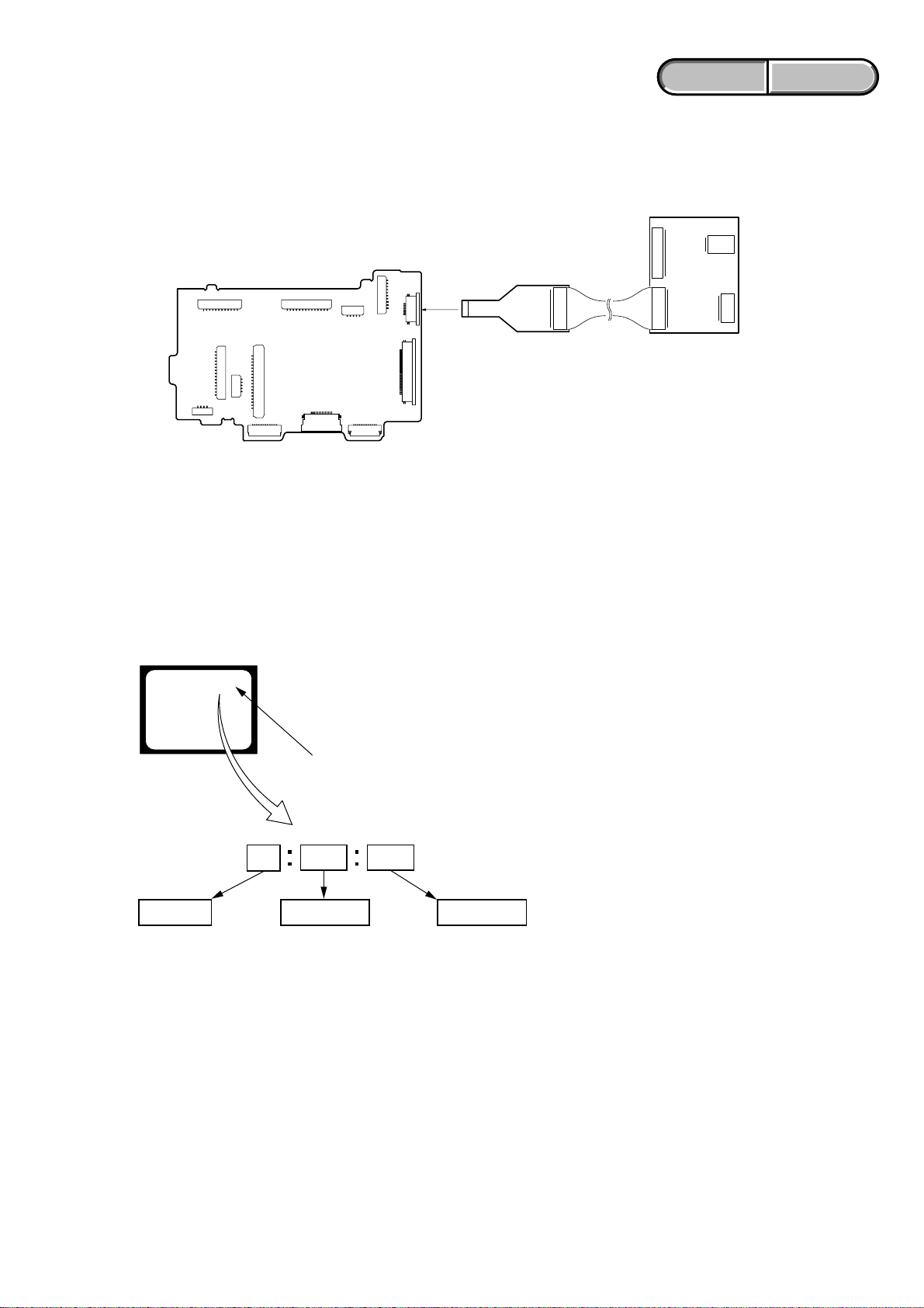
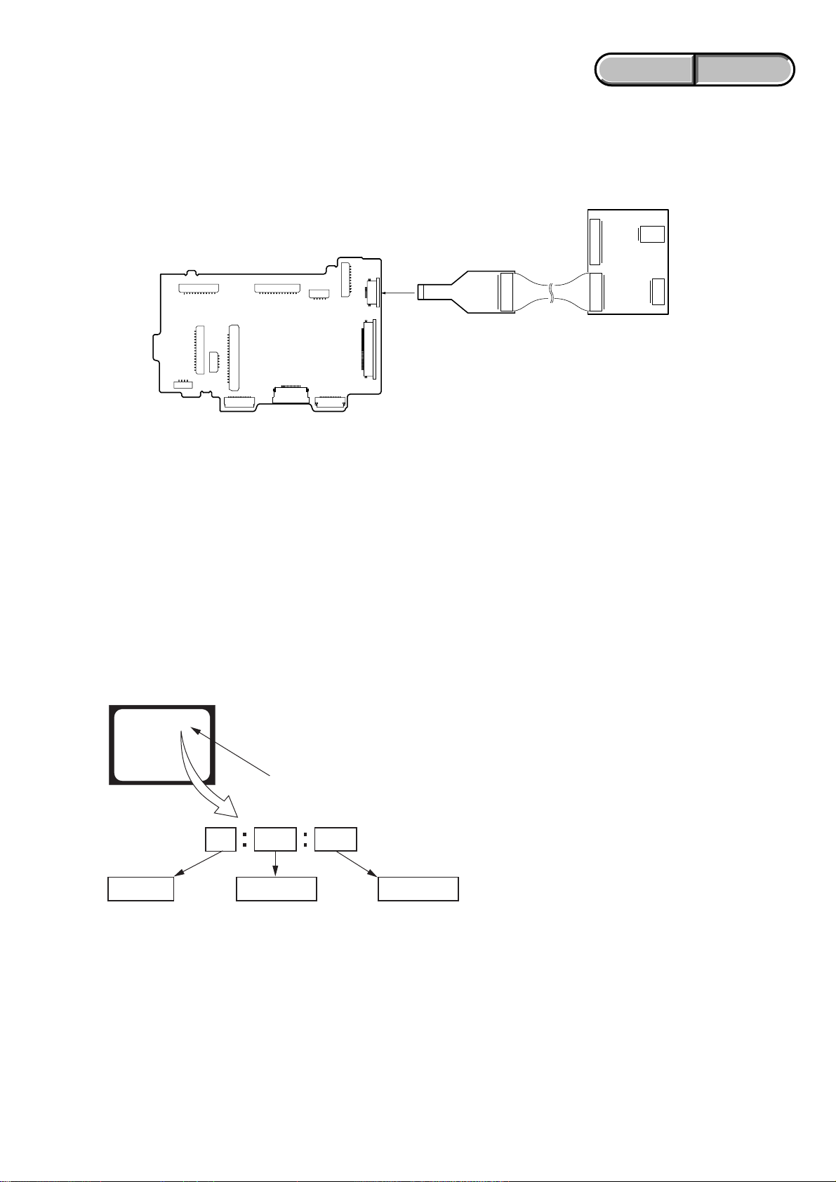
1-4. USING SERVICE JIG
Connect the CPC-15 jig connector (J-6082-564-A) and I/F unit for LANC control (J-6082-521-A) to the CN1014 of VC-525 board.
I/F unit for LANC control
(J-6082-521-A)
8
CN1014
VC-525 BOARD
(SIDE A)
1-5. SELF-DIAGNOSIS FUNCTION
1-5-1. Self-diagnosis Function
When problems occur while the unit is operating, the self-diagnosis
function starts working, and displays on the viewfinder or LCD
screen what to do.
Details of the self-diagnosis functions are provided in the Instruction
manual.
Viewfinder or LCD screen
C : 3 1 : 1 1
Blinks at 3.2Hz
1
CPC-15
(J-6082-564-A)
1-5-2. Self-diagnosis Display
When problems occur while the unit is operating, the counter of the
viewfinder or LCD screen shows a 4-digit display consisting of an
alphabet and numbers, which blinks at 3.2 Hz. This 5-character
display indicates the “repaired by:”, “block” in which the problem
occurred, and “detailed code” of the problem.
Repaired by:
C : Corrected by customer
H : Corrected by dealer
E : Corrected by service
engineer
DCR-HC62/HC62E_L2
3 1C
Block
Indicates the appropriate
step to be taken.
E.g.
31 ....Reload the tape.
32 ....Turn on power again.
1 1
Detailed Code
Refer to “1-5-3. Self-diagnosis Code Table”.
1-2
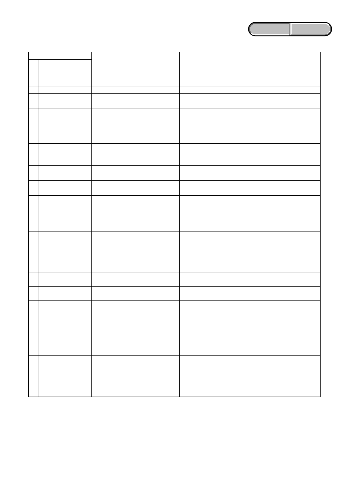
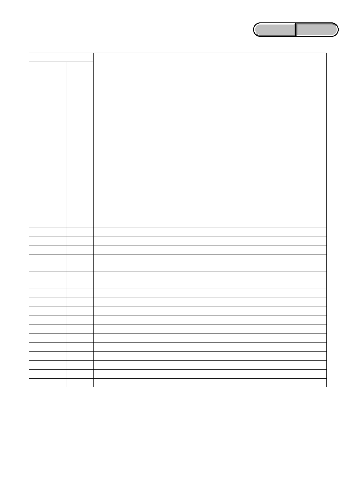
1-5-3. Self-diagnosis Code Table
Self-diagnosis Code
ENGLISH JAPANESE
ENGLISH JAPANESE
Repaired by:
C
C
C
C
C
C
C
C
C
C
C
C
C
C
C
C
C
C
C
C
C
C
C
C
C
C
C
C
C
Block
Function
04
21
22
31
31
31
31
31
31
31
31
31
31
31
31
31
32
32
32
32
32
32
32
32
32
32
32
32
32
Detailed
Code
00
00
00
10
11
20
21
22
23
30
31
40
41
42
43
44
10
11
20
21
22
23
30
31
40
41
42
43
44
Symptom/State
Non-standard battery is used.
Condensation.
Video head is dirty.
LOAD direction. Loading does not
complete within specified time
UNLOAD direction. Loading does not
complete within specified time
T reel side tape slacking when unloading
S reel
side tape slacking when unloading
T reel fault.
S reel fault.
FG fault when starting capstan.
FG fault during normal capstan operations.
FG fault when starting drum.
PG fault when starting drum.
FG fault during normal drum operations.
PG fault during normal drum operations.
Phase fault during normal drum operations.
LOAD direction loading motor timeout.
UNLOAD direction loading motor
time-out.
T reel side tape slacking when
unloading.
S reel side tape slacking when
unloading.
T reel fault.
S reel fault.
FG fault when starting capstan.
FG fault during normal capstan
operations.
FG fault when starting drum.
PG fault when starting drum.
FG fault during normal drum
operations.
PG fault during normal drum
operations.
Phase fault during normal drum
operations.
Correction
Use the InfoLITHIUM battery.
Remove the cassette, and insert it again after one hour.
Clean with the optional cleaning cassette.
Load the tape again, and perform operations from the beginning.
Load the tape again, and perform operations from the beginning.
.
Load the tape again, and perform operations from the beginning.
.
Load the tape again, and perform operations from the beginning.
Load the tape again, and perform operations from the beginning.
Load the tape again, and perform operations from the beginning.
Load the tape again, and perform operations from the beginning.
Load the tape again, and perform operations from the beginning.
Load the tape again, and perform operations from the beginning.
Load the tape again, and perform operations from the beginning.
Load the tape again, and perform operations from the beginning.
Load the tape again, and perform operations from the beginning.
Load the tape again, and perform operations from the beginning.
Remove the battery or power cable, connect, and perform
operations from the beginning.
Remove the battery or power cable, connect, and perform
operations from the beginning.
Remove the battery or power cable, connect, and perform
operations from the beginning.
Remove the battery or power cable, connect, and perform
operations from the beginning.
Remove the battery or power cable, connect, and perform
operations from the beginning.
Remove the battery or power cable, connect, and perform
operations from the beginning.
Remove the battery or power cable, connect, and perform
operations from the beginning.
Remove the battery or power cable, connect, and perform
operations from the beginning.
Remove the battery or power cable, connect, and perform
operations from the beginning.
Remove the battery or power cable, connect, and perform
operations from the beginning.
Remove the battery or power cable, connect, and perform
operations from the beginning.
Remove the battery or power cable, connect, and perform
operations from the beginning.
Remove the battery or power cable, connect, and perform
operations from the beginning.
DCR-HC62/HC62E_L2
1-3
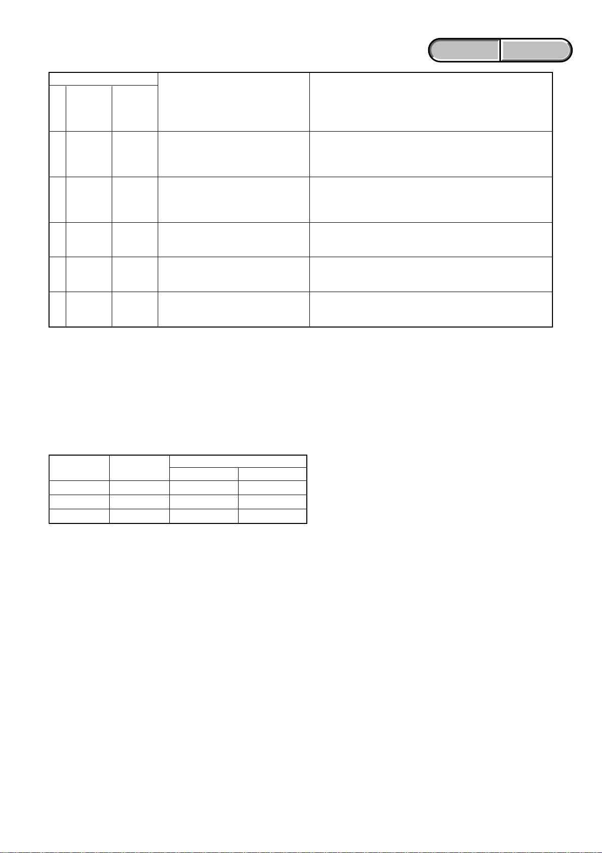
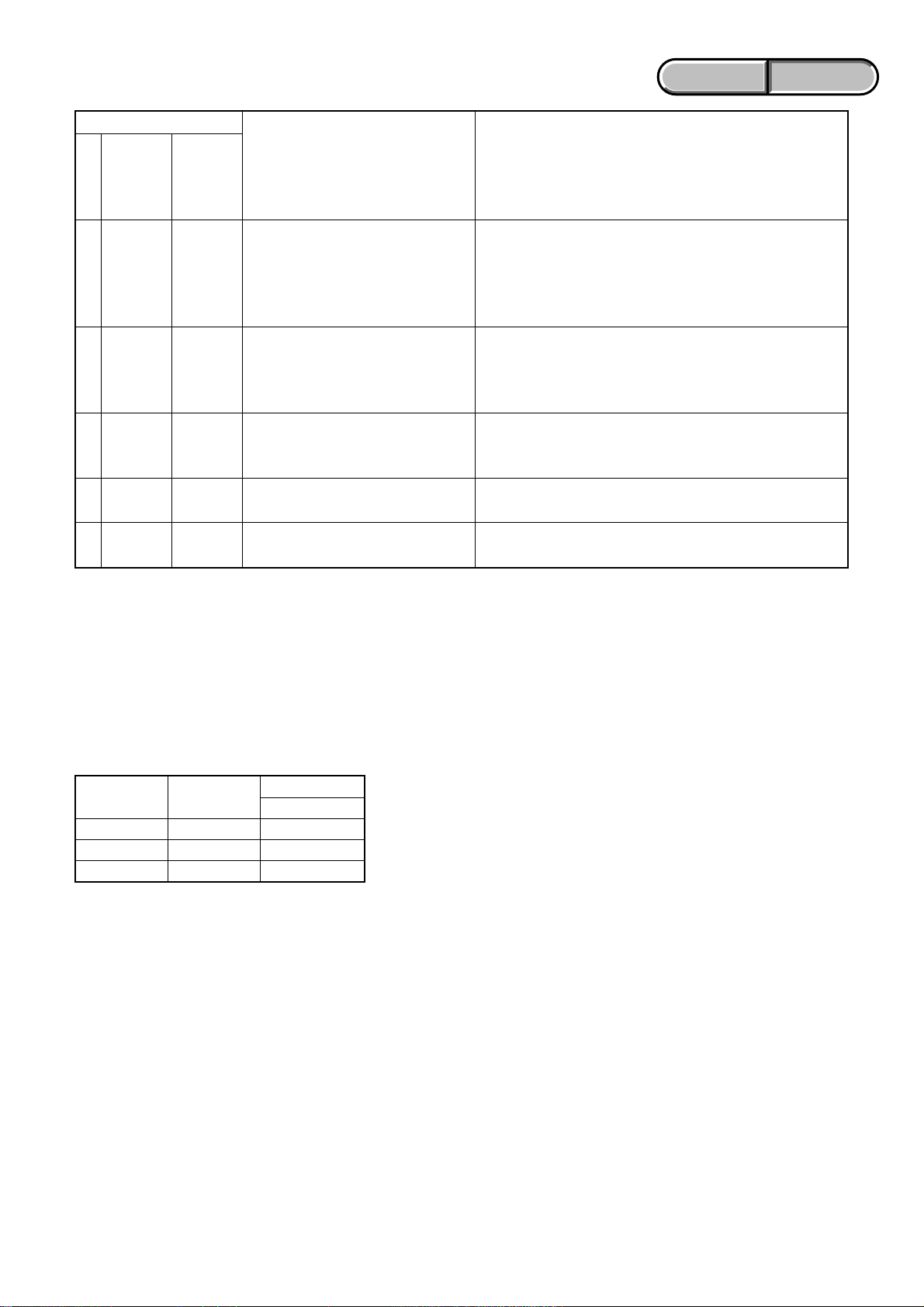
Self-diagnosis Code
ENGLISH JAPANESE
ENGLISH JAPANESE
Repaired by:
E
E
E
E
E
Block
Function
61
61
61
62
62
Detailed
Code
00
10
11
00
01
Symptom/State
Difficult to adjust focus
(Cannot initialize focus.)
Zoom operations fault
(Cannot initialize zoom lens.)
Focus lens initializing failure and zoom
lens initializing failure occur simultaneously.
Steadyshot function does not work well.
(With pitch angular velocity sensor output
stopped.)
Steadyshot function does not work well.
(With yaw angular velocity sensor output
stopped.)
Inspect the lens block focus reset sensor (Pin 7 of CN3801 of VC525 board) when focusing is performed when the touch panel is
operated in the focus manual mode and the focus motor drive circuit
(IC3802 of VC-525 board) when the focusing is not performed.
Inspect the lens block zoom reset sensor (Pin qa of CN3801 of
VC-525 board) when zooming is performed when the zoom switch
is operated and the zoom motor drive circuit (IC3802 of VC-525
board) when zooming is not performed.
Inspect the flexible board for breakage or loose connection.
If not faulty, inspect the focus and zoom motor drive circuit (IC3802
of VC-525 board).
Inspect pitch angular velocity sensor (SE7002 of CD-672 board)
peripheral circuits.
Inspect yaw angular velocity sensor (SE7001 of CD-672 board)
peripheral circuits.
1-6. PRECAUTION ON REPLACING THE VC-525 BOARD
Correction
Exif Model Data Check
When you replace to the repairing board, the written data of repairing board also might be changed to original setting.
When the data has changed because of board replaceing etc, check the data setting (Exif Model Data) is right. If not, rewrite to the right value.
Exif Model Data
36
32
00
Data
DCR-HC62E
36
32
45
Page
C
C
C
Writing Method:
1) Select page: 0, address: 01 and set data: 01.
2) Select page: C, address: D2 to D4, and set the Exif Model Data.
Note: To write in the non-volatile memory (EEPROM), press the PAUSE (Write) button each time to set the data.
3) Select page: 0, address: 01, and set data: 00.
Address
D2
D3
D4
DCR-HC62
DCR-HC62/HC62E_L2
1-4

ENGLISH JAPANESE
1. SERVICE NOTE
ENGLISH JAPANESE
1-1. 修理時の電源供給について
本機では,安定化電源(8.4Vdc)からバッテリ端子に電源を供給した場合,約10秒後にシャットオフし,動作しなくなります。
これを避けるため,下記の方法を用いてください。
方法:
DC入力端子を使用する。(ACアダプタ(AC-L200/L200B)を使用する。)
1-2. イジェクトしない時のカセット取出し方法(強制イジェクト)
1 2.DISASSEMBLYを参照し,メカデッキを外す。
2 カセコン組立を押さえながら,安定化電源より+4.5Vをローディングモータに加え,アンローディングさせる。
ローディングモータ
安定化電源(+4.5Vdc)
1-3. 強制電源ONモードの設定
調整リモコン(RM-95またはNEWLANCJIG)を使用して,電源を入れることが出来ます。
VTR操作は調整リモコンで行えます。
1-3-1. 強制カメラ電源ONモードの設定
1) ページ:0,アドレス:01にデータ:01をセット。
2) ページ:A,アドレス:10にデータ:01をセットしPAUSE(Write)ボタンを押す。
1-3-2. 強制VTR電源ONモードの設定
1) ページ:0,アドレス:01にデータ:01をセット。
2) ページ:A,アドレス:10にデータ:02をセットしPAUSE(Write)ボタンを押す。
1-3-3. 強制電源ONモードの解除
1) ページ:0,アドレス:01にデータ:01をセット。
2) ページ:A,アドレス:10にデータ:00をセットしPAUSE(Write)ボタンを押す。
3) ページ:0,アドレス:01にデータ:00をセット。
DCR-HC62/HC62E_L2
1-5
ENGLISH JAPANESE
ENGLISH JAPANESE
1-4. 使用サービス治具
CPC-15治具コネクタ(J-6082-564-A),LANC変換用I/F(J-6082-521-A)をVC-525基板CN1014に接続します。
I/F unit for LANC control
(J-6082-521-A)
8
CN1014
VC-525 BOARD
(SIDE A)
1-5. 自己診断機能
1-5-1. 自己診断機能について
本機の動作に不具合が生じたとき,自己診断機能が働き,
ビューファインダまたはLCD画面に,どう処置したらよい
か判断できる表示を行います。自己診断機能については取扱
説明書にも掲載されています。
ビューファインダまたはLCD画面
C : 3 1 : 1 1
1
CPC-15
(J-6082-564-A)
1-5-2. 自己診断表示
本機の動作に不具合が生じたとき,ビューファインダまたは
LCD画面のカウンタ表示部分がアルファベットと数字の4桁
表示になり,3.2Hzで点滅します。この5文字の表示によっ
て対応者分類および不具合の生じたブロックの分類,不具合
の詳細コードを示します。
対応者分類
C :お客さま自身で対応
H :販売店で対応
E :サービスエンジニア
で対応
DCR-HC62/HC62E_L2
3.2Hz点滅
3 1C
ブロック分類
対応方法の違いにより分類
例 31・・・テープを入れ直す
32・・・電源を入れ直す
1 1
詳細コード
「1-5-3.自己診断コード表」
を参照
1-6
1-5-3. 自己診断コード表
自己診断コード
対
応
者
C
C
C
C
C
C
C
C
C
C
C
C
C
C
C
C
C
C
C
C
C
C
C
C
C
C
C
C
C
ブロック
機能
04
21
22
31
31
31
31
31
31
31
31
31
31
31
31
31
32
32
32
32
32
32
32
32
32
32
32
32
32
詳細
コード
00
00
00
10
11
20
21
22
23
30
31
40
41
42
43
44
10
11
20
21
22
23
30
31
40
41
42
43
44
症状/状態
標準でないバッテリを使用している
結露している
ビデオヘッドが汚れている
LOAD方向,ローディング所定時間
内終了せず
UNLOAD方向,ローディング所定時
間内終了せず
UNLOAD時,Tリール側テープ弛み
UNLOAD時,Sリール側テープ弛み
Tリール異常
Sリール異常
キャプスタン起動時FG異常
キャプスタン定常時FG異常
ドラム起動時FG異常
ドラム起動時PG異常
ドラム定常時FG異常
ドラム定常時PG異常
ドラム定常時位相異常
LOAD方向,ローディング所定時間
内終了せず
UNLOAD方向,ローディング所定時
間内終了せず
UNLOAD時,Tリール側テープ弛み
UNLOAD時,Sリール側テープ弛み
Tリール異常
Sリール異常
キャプスタン起動時FG異常
キャプスタン定常時FG異常
ドラム起動時FG異常
ドラム起動時PG異常
ドラム定常時FG異常
ドラム定常時PG異常
ドラム定常時位相異常
ENGLISH JAPANESE
ENGLISH JAPANESE
対応/方法
インフォリチウムバッテリを使用する
カセットを取り出して,約1時間してからもう一度入れ直す
別売のクリーニングカセットできれいにする
テープを入れ直し,再度操作し直す
テープを入れ直し,再度操作し直す
テープを入れ直し,再度操作し直す
テープを入れ直し,再度操作し直す
テープを入れ直し,再度操作し直す
テープを入れ直し,再度操作し直す
テープを入れ直し,再度操作し直す
テープを入れ直し,再度操作し直す
テープを入れ直し,再度操作し直す
テープを入れ直し,再度操作し直す
テープを入れ直し,再度操作し直す
テープを入れ直し,再度操作し直す
テープを入れ直し,再度操作し直す
バッテリまたは電源ケーブルを外して付け直し,再度操作し直す
バッテリまたは電源ケーブルを外して付け直し,再度操作し直す
バッテリまたは電源ケーブルを外して付け直し,再度操作し直す
バッテリまたは電源ケーブルを外して付け直し,再度操作し直す
バッテリまたは電源ケーブルを外して付け直し,再度操作し直す
バッテリまたは電源ケーブルを外して付け直し,再度操作し直す
バッテリまたは電源ケーブルを外して付け直し,再度操作し直す
バッテリまたは電源ケーブルを外して付け直し,再度操作し直す
バッテリまたは電源ケーブルを外して付け直し,再度操作し直す
バッテリまたは電源ケーブルを外して付け直し,再度操作し直す
バッテリまたは電源ケーブルを外して付け直し,再度操作し直す
バッテリまたは電源ケーブルを外して付け直し,再度操作し直す
バッテリまたは電源ケーブルを外して付け直し,再度操作し直す
DCR-HC62/HC62E_L2
1-7
自己診断コード
対
ブロック
応
機能
者
E
61
E
61
E
61
E
62
E
62
詳細
コード
00
10
11
00
01
(フォーカスの初期化ができない)
(PITCH角速度センサ出力張り付き)
(YAW角速度センサ出力張り付き)
症状/状態
フォーカスが合いにくい
ズーム動作の異常(ズームレンズの
初期化ができない)
フォーカスレンズ初期化異常,ズー
ムレンズ初期化異常の同時発生
手振れ補正が効きにくい
手振れ補正が効きにくい
ENGLISH JAPANESE
ENGLISH JAPANESE
対応/方法
フォーカス手動モードでタッチパネルを操作した時,
フォーカス動作をすればレンズブロックのフォーカスリ
セットセンサ(VC-525基板CN38017ピン)を点検。フォー
カス動作をしなければフォーカスモータドライブ回路(VC525基板IC3802)を点検。
ズームレバーを操作した時,ズーム動作をすればレンズブ
ロックのズームリセットセンサ(VC-525基板CN3801qaピ
ン)を点検。ズーム動作をしなければズームモータドライブ
回路(VC-525基板IC3802)を点検。
フレキシブル基板の切れ,半挿しを点検。
問題がなければフォーカス,ズームモータドライブ回路
(VC-525基板IC3802)を点検。
PITCH角速度センサ(CD-672基板SE7002)周辺回路点検
YAW角速度センサ(CD-672基板SE7001)周辺回路点検
1-6. VC-525基板交換時の注意
Exif機種データ確認
補修用基板と交換する時,補修用基板に書かれているデータは元の設定と違っている場合があります。
基板交換などでデータが変更された場合は,Exif機種データが正しいか確認し,違っている場合は正しい値に書き換えて下
さい。
Exif機種データ
ページ アドレス
CD2 36
CD3 32
CD4 00
書き換え方法:
1) ページ:0,アドレス:01にデータ:01をセットする。
2) ページ:C,アドレス:D2〜D4にExif機種データをセットする。
注: 不揮発性メモリ(EEPROM)に書き込むため,データをセットする度にPAUSE(Write)ボタンを押してください。
3) ページ:0,アドレス:01にデータ:00をセットする。
データ
DCR-HC62
DCR-HC62/HC62E_L2
1-8E

2. DISASSEMBLY
Cut and remove the part of gilt
which comes off at the point.
(Be careful or some
pieces of gilt may be left inside)
NOTE FOR REPAIR
• Make sure that the flat cable and flexible board are not cracked of bent at the terminal.
Do not insert the cable insufficiently nor crookedly.
• When remove a connector, don’t pull at wire of connector. It is possible that a wire is snapped.
• When installing a connector, don’t press down at wire of connector.
It is possible that a wire is snapped.
DCR-HC62/HC62E_L2
2-1
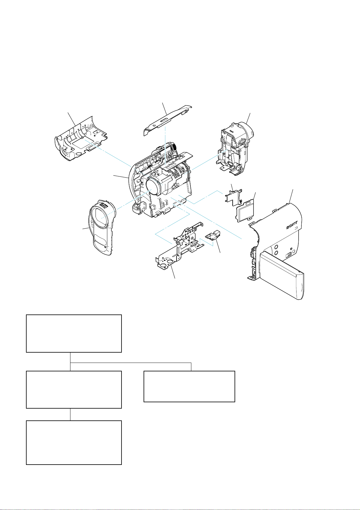
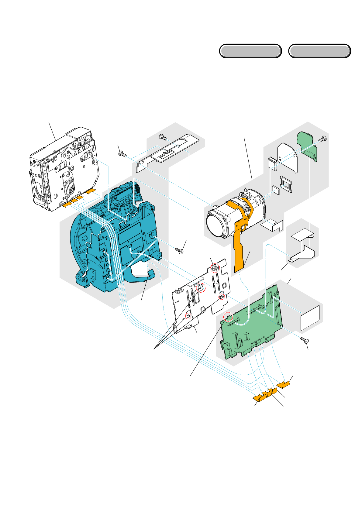
2-1. IDENTIFYING PARTS
Cabinet (L)
Cabinet (L) Section
⋅ VC-525 Board
⋅ CD-672 Board
Cabinet (Upper (2122))
MS Cabinet
BT-EVF Section
⋅ LB-138 Board
⋅
AV-126 Board
⋅ FP-626 Flexible Board
Cabinet (R) Section
⋅ CF-112 Board
⋅ PD-359 Board
⋅ FP-386 Flexible Board
MS-398 Board
⋅ FP-625 Flexible Board
Front Cabinet Block
- DISASSEMBLY FLOW -
2-2-1. OVERALL SECTION
- Front Cabinet Block
- Microphone Unit
- Cabinet (L)
- Cabinet (Upper (2122))
2-2-2. BOTTOM FRAME SECTION
- JK-368 Board
- MS-398 Board
- Bottom Frame
- BT-EVF Section
JK-368 Board
Bottom Frame
2-2-4. CABINET (R) SECTION
- Loud Speaker
- CF-112 Board
- LCD Panel Block
2-2-3. CABINET (L) SECTION
- VC-525 Board
- CD-672 Board
- Lens Block
- Mechanism Deck
- Control Key Block (SS21200)
DCR-HC62/HC62E_L2
2-2

HELP
EXPLODED VIEW
HELP
2-2. DISASSEMBLY
2-2-1. OVERALL SECTION
Follow the disassembly in the numerical order given.
1 Cabinet (R) Section (1-1 to 1-14)
2 Front Cabinet Block (2-1 to 2-6)
2-1 (#2)
Bottom Frame
Section
(See Page 2-4)
2-3
2-4 (#1)
1-1
(Open)
1-2 (#2)
1-3
1-5
1-4
Note:On installation of the NS knob,
adjust the position of the NS
switch and the NS knob.
1-6
(#2)
1-12
(Boss)
HARDWARE LIST
1 Cabinet (R)
Section
(See Page 2-6)
1-11
(Boss)
1-10
(Claw)
2-2 (#2)
2-5 (#1)
2-6
2 Front Cabinet
Block
1-14
1-13
1-7
(#2)
1-9
(#2)
1-8
(Open)
DCR-HC62/HC62E_L2
2-3
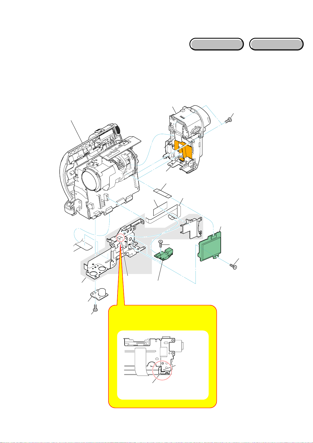
2-2-2. BOTTOM FRAME SECTION
EXPLODED VIEW
Follow the disassembly in the numerical order given.
1 BT-EVF Section (1-1 to 1-3)
2 MS-398 Board (2-1 to 2-9)
3 JK-368 Board (3-1)
Cabinet (L) Section
(See Page 2-5)
HARDWARE LIST
1 BT-EVF Section
1-1 (#2)
1-2
1-3
2-1
2-2
2-6
2-3 (#1)
2-4
2-8
2-9
3-1 (#3)
2-5 (Claw)
3 JK-368
Board
Note: On installation of the bottom frame,
insert the claw of the bottom frame
to the hole of the MD frame.
2 MS-398 Board
S-398
M
2-7 (#3)
DCR-HC62/HC62E_L2
Claw
(Bottom Frame)
Hole
(MD Frame)
2-4
2-2-3. CABINET (L) SECTION
EXPLODED VIEW
Follow the disassembly in the numerical order given.
1 Lens Block (1-1 to 1-3)
2 VC-525 Board (2-1 to 2-8)
3 Mechanism Deck (3-1 to 3-3)
3 Mechanism Deck
HARDWARE LIST
1-2 (#12)
2-3
3-3 (#15)
1 Lens Block
2-6
(Claw)
1-1
1-3
CD672
2 VC-525
Board
DCR-HC62/HC62E_L2
3-1 (Claw)
3-2
2-5 (Claw)
2-5
2-2
VC-525
2-4 (#3)
2-1
2-8
2-7
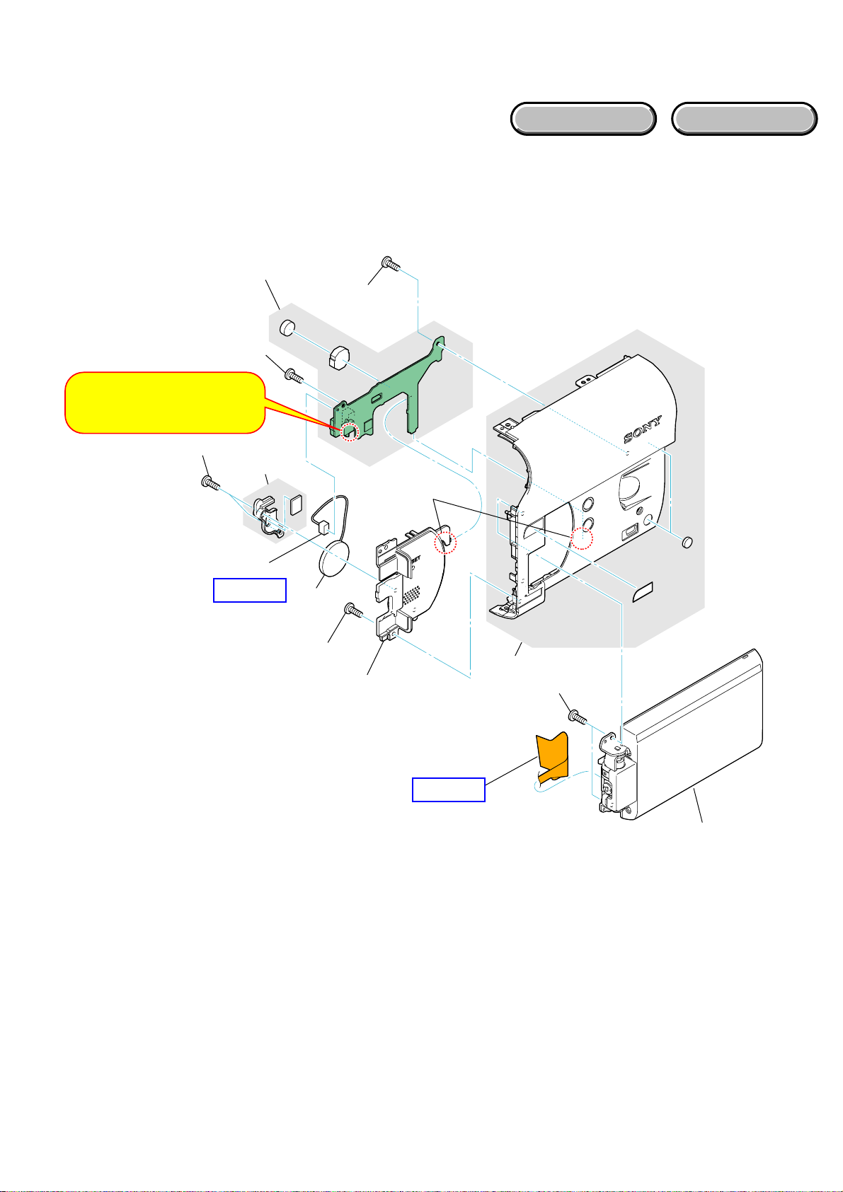
2-2-4. CABINET (R) SECTION
EXPLODED VIEW
Follow the disassembly in the numerical order given.
1 CF-112 Board (1-1 to 1-7)
2 LCD Panel Block (2-1 to 2-4)
1 CF-112 Board
1-5 (#12)
1-6 (#12)
Note:On installation of the CF-112
board, adjust the position of
the Panel Open/Close switch.
1-2 (#12)
1-3
HARDWARE LIST
1-7
(Claw)
1-1
HELP01
1-4
2-1 (#12)
2-2
2-4
2-3 (#12)
HELP02
2 LCD Panel
Block
DCR-HC62/HC62E_L2
2-6E
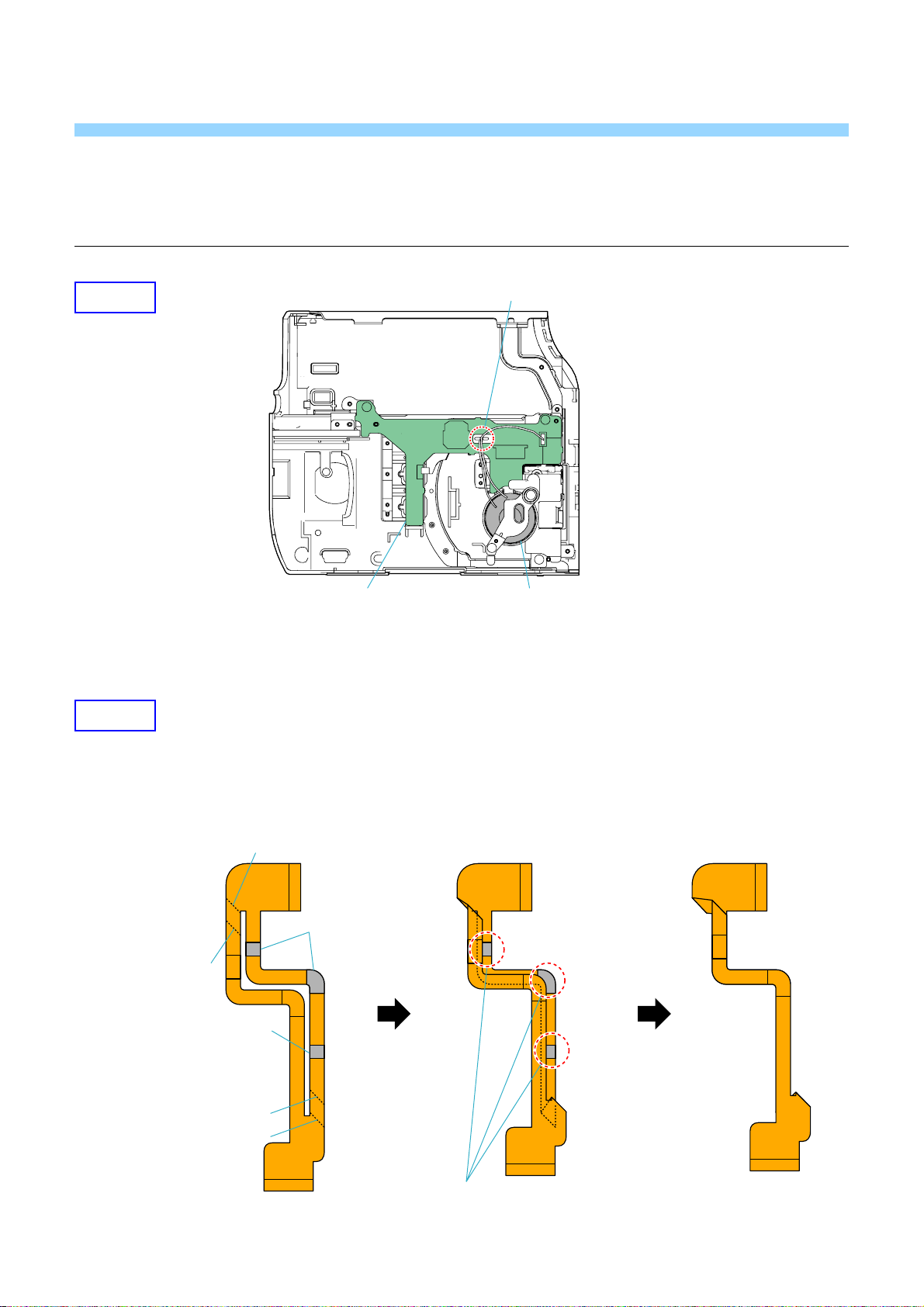
HELP
Sheet attachment positions and procedures of processing the flexible boards/harnesses are shown.
HELP01
HELP02
Harness arrangement
Loud SpeakerCF-112 Board
THE METHOD OF ATTACHMENT OF FP-625 FLEXIBLE BOARD
1 Fold dotted line parts of the FP-625 flexible board
as shown in figure.
Valley fold
Adhesive tape
Mountain
fold
Adhesive tape
Valley fold
Mountain
fold
Stick it together in the adhesive tape
while bending the FP-625 flexible board.
DCR-HC62/HC62E_L2
HELP
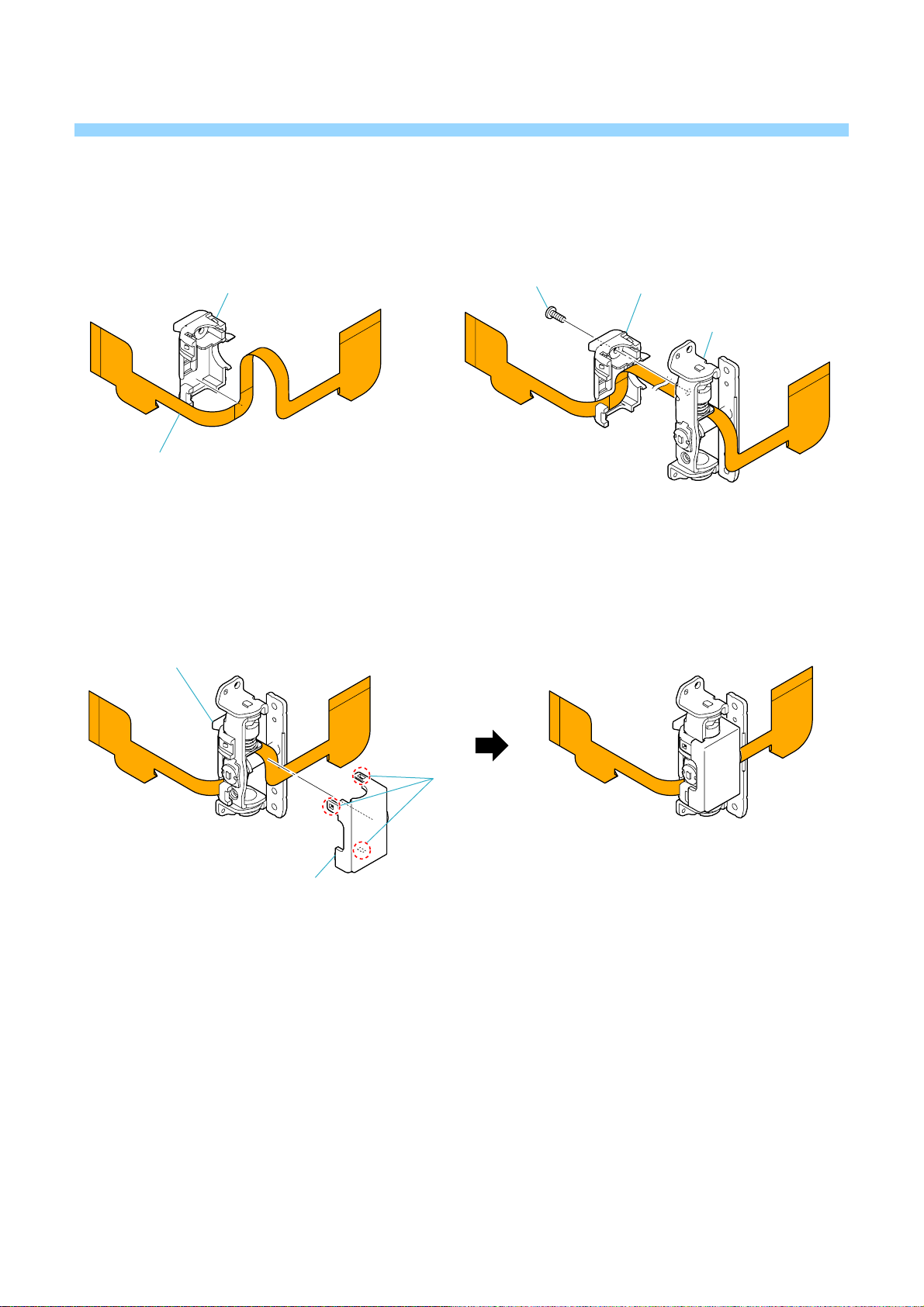
2 Put the FP-625 flexible board on the
hinge cover (M).
3 Fix hinge cover (M) and the panel hinge assy (M)
with the screw.
Hinge cover (M)
FP-625 flexible board
4 Install the hinge cover (C) in the hinge cover (M).
Hinge cover (M)
Screw
Hinge cover (M)
Panel hinge assy (M)
Hinge cover (C)
Claw
DCR-HC62/HC62E_L2
HELP
Link
Link
3. BLOCK DIAGRAMS
OVERALL BLOCK DIAGRAM (1/6)
OVERALL BLOCK DIAGRAM (2/6)
OVERALL BLOCK DIAGRAM (3/6)
OVERALL BLOCK DIAGRAM (4/6)
OVERALL BLOCK DIAGRAM (5/6)
OVERALL BLOCK DIAGRAM (6/6)
POWER BLOCK DIAGRAM (1/3)
POWER BLOCK DIAGRAM (2/3)
POWER BLOCK DIAGRAM (3/3)
DCR-HC62/HC62E_L2
3. BLOCK DIAGRAMS
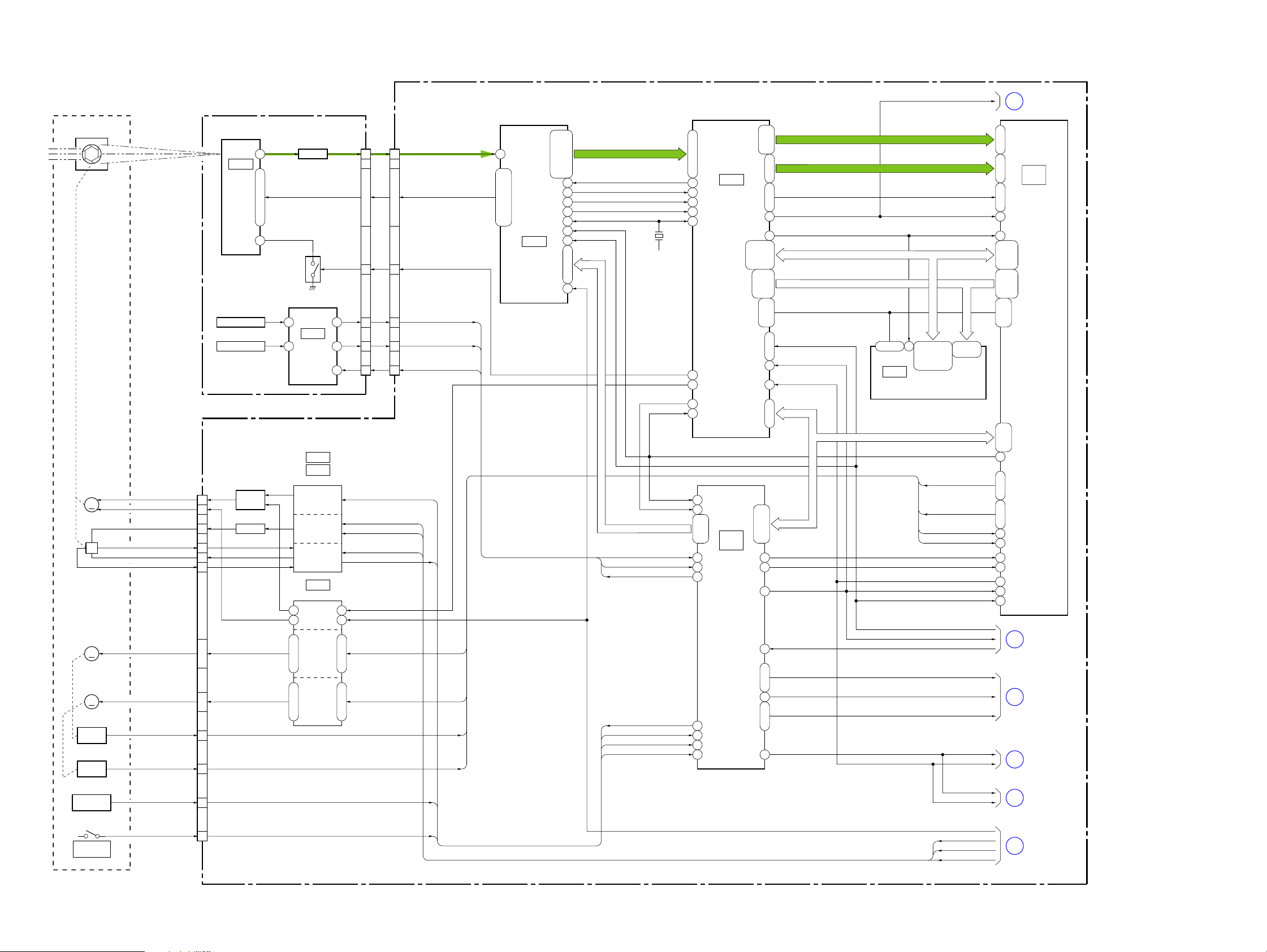
3-1. OVERALL BLOCK DIAGRAM (1/6) ( ) : Number in parenthesis ( ) indicates the division number of schematic diagram where the component is located.
LENS BLOCK
IRIS
(SHUTTER)
IRIS
METER
M
H
FOCUS
MOTOR
M
ZOOM
MOTOR
M
FOCUS
SENSOR
ZOOM
SENSOR
LENS TEMP
SENSOR
IRIS_DRIVE (-)
IRIS_DRIVE (+)
IRIS_BIAS (-)
IRIS_HALL (-)
IRIS_BIAS (+)
IRIS_HALL (+)
FOCUS_XA, FOCUS_A,
FOCUS_XB, FOCUS_B
ZOOM_A, ZOOM_XA,
ZOOM_XB, ZOOM_B
FC_SENSE_OUT
ZM_SENSE_OUT
TEMP_OUT
CD-672 BOARD
IC7002
IMAGER
SE7002
PITCH SENSOR
SE7001
YAW SENSOR
CN3801
14
13
17
18
15
16
21 - 241 - 4
7
11
6
CCD
Q3801
IRIS
DRIVE
Q3803
AMP
12
V1 - V6, RG, H1, H2, SUB
7 - 2, 14, 18, 16, 19
1
Q7001
8
12
F3 G1
Q7002
CLAMP
IC7003
PITCH/YAW
SENSOR
AMP
IC3803
IC3804
(5/18)
IRIS DRIVE
HALL GAIN
HALL AMP
IC3802
(5/18)
IRIS DRIVE
FOCUS
MOTOR
DRIVE
F2, E2, D2, B1C6, B7, E6, D6
ZOOM
MOTOR
DRIVE
CN7001
RCSUB
2
18
19
E4F4
D5, B6, A6, C5 F5, G6, D3, E3
27
7
4
2
3
EN0, DIR0A, DIR0B
EN1, DIR1A, DIR1B
CN3201
2
23, 20 - 15, 12, 10, 8
6, 9 - 14, 17, 19, 21
22
25
27
26
IRIS_PWM
HALL_GAIN
HALL_REF
HALL_OFFSET
I_HALL_AD
SHUTTER_ON
CAM_DD_ON
FC_RST
ZM_RST
LENS_TEMP_AD
VC-525 BOARD (1/6)
CCD_OUT+
CSUB
PITCH_AD
YAW_AD
VST_C_RESET
K4
C8, C1, B7, B1, A1
H10, G8, F8, E8, C9,
IC3201
A/D CONVERTER,
TIMING
GENERATOR
(4/18)
AD2 - AD13
B8 - B10, C7,
E10, F9, F10, G9
C10, D8, D9, E9,
TG_HD
C5
TG_ID
J9
VSG1
G2 83
ZV1
J2
CHCK
A8
CAM_VD
C4
XSYS_RST
B6
X3201
33MHz: HC62
K9, J10, J6, H9
H2
CAM_DD_ON
CH_CS, CH_SI, CH_SO, CH_SCK
27MHz: HC62E
CAM_VD
XSYS_RST
SHUTTER_ON
PITCH_AD
YAW_AD
VST_C_RESET
IRIS_PWM
I_HALL_AD
LENS_TEMP_AD
XNS_SW
CSUB
TG_FLD
CAM_VD
58, 59, 62 - 71
IC3901
92
CAMERA SIGNAL
84
PROCESS
(6/18)
82
137
195 - 191,
99
98
90
25
A7
D13
IC5301
AC9, Y9
Y6, Y10,
(1/2)
CAMERA
P22
CONTROL
P23
(16/18)
T2
Y16
P20
R22
A13 Y18
VCK
IFI_HD, IFI_VD, IFI_OE
38
IC4002
(7/18)
CAM_VD
IFI_Y0 - IFI_Y7
IFI_C0 - IFI_C3
VCK
MEMCK_OUT
MDQ0 - MDQ15
MA0 - MA13
2, 4, 5, 7, 8,
10, 11, 13, 42,
44, 45, 47, 48,
50, 51, 53
EN0, DIR0A, DIR0B
EN1, DIR1A, DIR1B
FC_RST
ZM_RST
XPWAD, XPWDAXPWAD, XPWDA
20 - 26,
29 - 35
SSSSSS
XWENXWEN
SPCK
SYS_VSYS_V
XSYS_RST
XSYS_RST
SYS_V
ZOOM_VR_AD
XCS_AU1
DEM0, DEM1DEM0, DEM1
XRST_VTR
SPCK
XRST_VTR
SPCK
199
208 - 202,
9 - 611 - 13
115
167
175, 174
188 - 185,
182 - 178,
145, 144
161 - 156,
153 - 148,
MXWE, MXCAS, MXRAS, MXCS0
166, 163
169, 168,
XSYS_RST
32, 108, 109
SYS_V
24
SPCK
122
20 - 23
CAM_SI, CAM_SO, CAM_SCK, CAM_CS
AB10, C22
AB11, Y11,
AB5 166
AC5 167
D14
ZOOM_VR_AD
M22
Y17, L20
XCS_AU1
U2
AC10, L23
XRST_VTR
16 - 19
64M SDRAM
CAM_SI, CAM_SO, CAM_SCK
1
216 - 223224 - 227228 - 230
VIDEO DSP,
LENS CONTROL
241
196
208, 207,
205 - 198
215 - 210,
171, 170
174, 173,
185 - 176,
189, 190
186, 187,
156
159, 158,
236
239, 246, 247248, 250, 251
237
238
139
157
141
2
3
4
5
OVERALL (2/6)
(PAGE 3-2)
IC4001
(1/4)
(7/18)
OVERALL (6/6)
(PAGE 3-6)
OVERALL (5/6)
(PAGE 3-5)
OVERALL (3/6)
(PAGE 3-3)
OVERALL (4/6)
(PAGE 3-4)
NIGHTSHOT
PLUS
DCR-HC62/HC62E_L2
NS_SW
19
A : VIDEO SIGNAL
XNS_SW
3-1
CAM_DD_ON
HALL_GAIN
HALL_REF
HALL_OFFSET
6
OVERALL (6/6)
(PAGE 3-6)
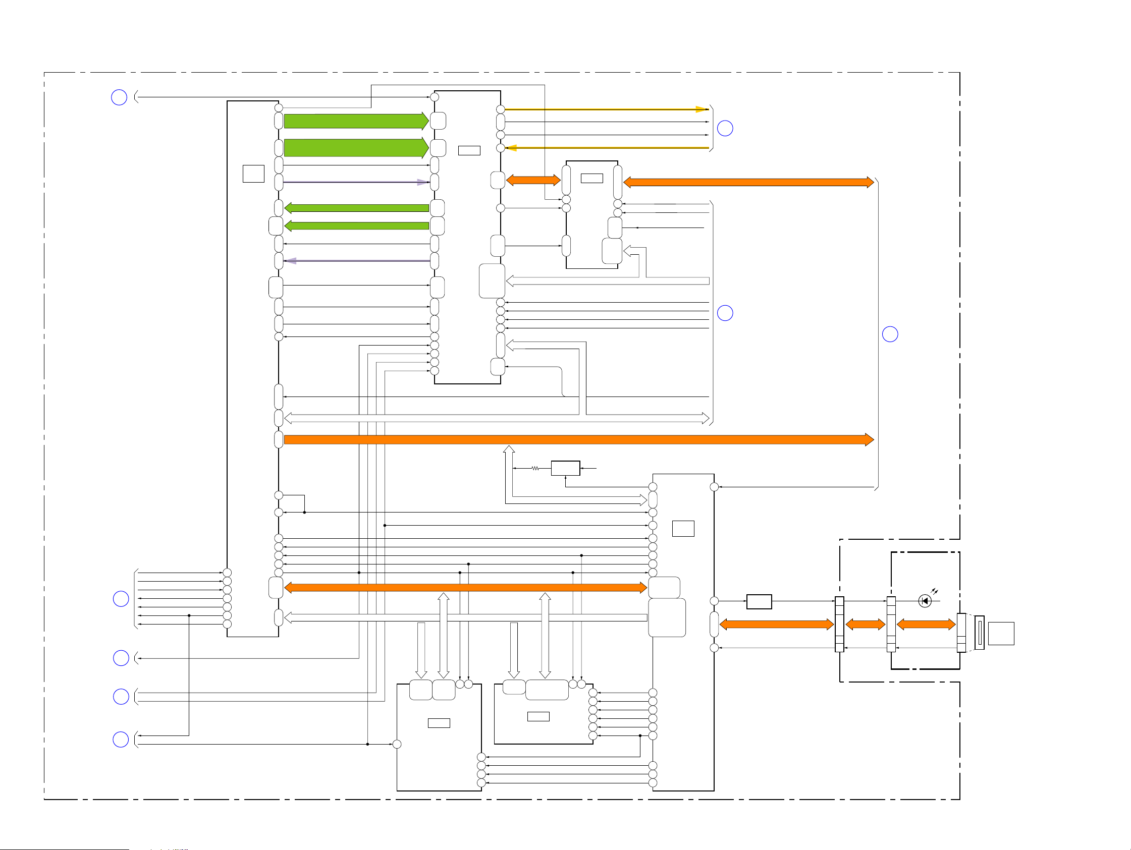
3-2. OVERALL BLOCK DIAGRAM (2/6)
VC-525 BOARD (2/6)
OVERALL (1/6)
(PAGE 3-1)
VCK VCK
1
IC4001
(2/4)
VIDEO/AUDIO
DSP
(7/18)
20
268 - 271
279 - 282
287, 288301, 302
264 - 267
275, 276
272, 273,
284, 285
298, 299
72, 289,
290, 291
73, 292
293, 294
283
( ) : Number in parenthesis ( ) indicates the division number of schematic diagram where the component is located.
LCKO
RYO0_DEHD, RYO1_DEVD,
RYO2_DEFLD, RYO3_SGOUT
RCO0_EDHD, RCO1_EDVD,
RCO2_EDFLD, RCO3_FRMREF
HYO_SLGATE, HCO_FYI1
ADATAIN0, ADATAIN1
RYI0_DE0 - RYI3_DE3
RCI0_DE4 - RCI3_DE7
HYI_PLL27IN, HCI_FYIO
ADATAOUT0,1
FRAT_REF0, FLAT_SYNC_FYO0,
VLAT_SYNC_FCI, VLAT_IN_FYO1
FS_EDGE_REF, TFS_FCO
THYRQ_FVDI, THCRQ_FHDI
MFLG_QRST
DSCK_VM
XSYS_RST
SFD_BCK
SFD_LRCK
143
119, 162,
121,
70,
164, 165168, 127
13, 72
123 - 125,
12, 75
167, 126
18, 76,
118, 128
68, 161
19
15
62
21
78
120, 163
, 122
71
14, 73
166
77, 169
IC4201
DV SIGNAL
PROCESS
(9/18)
RECDT
45
RECA1, RECA2
48, 47
RECCK
41
RFIN
139
LBUS0 - LBUS3
150, 187
149, 186,
104
XACC, XENA, FCLR,
106, 151
51, 53, 105,
54, 55, 57,
152 – 155,
189, 190, 192
107, 109, 110,
156
188
XCS_IC_4201
158
60
VSP_SI, VSP_SO, XVSP_SCK
157, 114, 3
FRRV, TRRV,
TRRT, DRP
111, 59
58, 112,
TRCKO
FRL, DIR
RECDT
RECA1, RECA2
IC4101
DV
24, 26 - 28
INTERFACE
62
(8/18)
19
12 - 15, 17
D24A00 - D31A07, DXXA08, DXXA09, ALE, WRX, RDX
TPA+, TPA-, TPB+, TPB-
52, 51, 48, 47
78
39
43, 80
16, 41, 42,
2 - 4,
75 - 77
6 - 9, 11,
XCS_IC_4101
IC_4101_SLEEP
OFR, XDVCN, LPS,
XRST_PHY, XRST_LINK
D24A00 - D31A07,
ALE, WRX, RDX
ATF_LATCHATF_LATCH
CS_IC_4201_BUSCS_IC_4201_BUS
XCS_IC_4201
RECCK
RFIN
SWPSWP
11
12
OVERALL (3/6)
(PAGE 3-3)
OVERALL (3/6)
(PAGE 3-3)
TPA+, TPA-, TPB+, TPB-
13
OVERALL (5/6)
(PAGE 3-5)
OVERALL (3/6)
(PAGE 3-3)
OVERALL (4/6)
(PAGE 3-4)
OVERALL (5/6)
(PAGE 3-5)
OVERALL (6/6)
(PAGE 3-6)
10
7
8
9
XCS_IC_4001_2
IC_4001_CS
USB_XEN
VFI_OE
IC_4001_1_VD
LINEOUT_V
VREF
DSCK_VM
SFD_BCK
SFD_LRCK
LINEOUT_V
XSYS_RST
149
154
80
160
161
164
165
86, 168, 169
150 - 152
28, 29
79
24
147
144
145
148
119
122, 121
137 - 124,
116 - 98
USB_CLK
JAIRQ
LXCS
LXWR
LXWAIT
DSCK_VM
D0_VM - D15_VM
A1_VM - A19_VM
TRRT, FRRV, TRRV
VSP_SI, VSP_SO, XVSP_SCK
D0_VM - D15_VM
A1_VM - A21_VM
2 - 11,
33 - 36,
20 - 27,
39 - 46,
30, 31, 55
49 - 52
IC5202
32M FLASH
13
(15/18)
LXWAIT
DSCK_VM
15
53
12
18
32
19
USB_D+
USB_D+, USB_D-
A13_VM
A1_VM - A11_VM,
2, 3, 5, 6, 8, 9, 11,
19 - 24,
12, 39, 40, 42, 43,
27 - 32
45, 46, 48, 49
IC5203
16M SDRAM
(15/18)
Q4005
PULL UP
USB_APPOLLO_PULLUP
LXWR
DSCK_VM
D0_VM - D15_VM
35
15
USB_3.1V
USB_D+, USB_D-
USB_CLK
SFD_LRCK
JAIRQ
LXCS
LXWR
LXWAIT
DSCK_VM
D0_VM - D15_VM
A1_VM - A21_VM
XCS_SDRAM_VM
18
WE0_VM
14
CAS_VM
16
RAS_VM
17
CKE_VM
34
WE1_VM
36
WE1_VM
XBS_VM
RD_VM
XCS_FLASH
FRRV, TRRV, TRRT, DRP
VSP_SI, VSP_SO, XVSP_SCK
V12
N1, P1
L1
C7
IC5101
(1/3)
W4
DS CONTROL
B16
(14/18)
B17
V19
A10
K18 - K21
F19 - F21,
J18 - J21,
G19, G20,
H18 - H20,
AA18, AA19
R18, R19, T19,
L20, M18, M19,
W18 - W21, Y19,
N18,N19, P18, P19,
U19, U20, V20, V21,
C17
A19
B18
C16
C18
B19
D21
E21
A18
M2
Q5101
Y18
A14, C15, D14
A15
LED
DRIVE
MS_DIO, MS_BS, MS_SCLK
XMS_LED_ON
MS_XIN MS_INSERT
USB_D+, USB_D-USB_D+, USB_D-
USB_DET
MS-398 BOARD
(MS ACCESS)
CN1011
2 9
4, 5, 7
6
CN602
4, 6, 7
5
DIO, BS, SCLK
A : VIDEO SIGNAL
A : AUDIO SIGNAL
A : VIDEO/AUDIO SIGNAL
A : VIDEO/AUDIO/SERVO SIGNAL
D601
INS
CN601
6
4, 2, 8
MEMORY
STICK
DUO
DCR-HC62/HC62E_L2
3-2
 Loading...