

Sony DAV-S880 User Manual
Compact AV
System
Operating Instructions
4-241-069-11(1)
DAV-S880
© 2002 Sony Corporation
WARNING
To prevent fire or shock
hazard, do not expose the unit
to rain or moisture.
Do not install the appliance in a
confined space, such as a bookcase
or built-in cabinet.
To prevent fire, do not cover the
ventilation of the apparatus with
news papers, table-cloths, curtains,
etc. And don’t place lighted candles
on the apparatus.
To prevent fire or shock hazard, do
not place objects filled with liquids,
such as vases, on the apparatus.
This appliance is classified as a
CLASS 1 LASER product. The label
is located on the bottom exterior.
Don’t throw
away the battery
with general
house waste,
dipose of it
correctly as
chemical waste.
Except for the European
models
ENERGY STA R
registered mark.
ENERGY STA R
As an
Sony Corporation has
determined that this product
meets the
guidelines for energy efficiency.
®
is a U.S.
®
ENERGY STA R
partner,
®
Precautions
Safety
• If anything falls into the cabinet,
unplug the unit and have it
checked by qualified personnel
before operating it any further.
• The unit is not disconnected from
the mains as long as it is
connected to the mains outlet,
even if the unit itself has been
turned off.
• Unplug the unit from the wall
outlet if you do not intend to use it
for an extended period of time. To
disconnect the cord, pull it out by
the plug, never by the cord.
Installing
• Do not install the appliance in a
confined space, such as a bookcase
or built-in cabinet.
• Allow adequate air circulation to
prevent internal heat buildup.
• Do not place the unit on surfaces
(rugs, blankets, etc.) or near
materials (curtains, draperies) that
may block the ventilation slots.
• Do not install the unit near heat
sources such as radiators, or air
ducts, or in a place subject to
direct sunlight, excessive dust,
mechanical vibration, or shock.
• Do not install the unit in an
inclined position. It is designed to
be operated in a horizontal
position only.
•Keep the unit and discs away from
equipment with strong magnets,
such as microwave ovens, or large
loudspeakers.
• Do not place heavy objects on the
unit.
• If the unit is brought directly from
a cold to a warm location,
moisture may condense inside the
Compact AV System and cause
damage to the lenses. When you
first install the unit, or when you
move it from a cold to a warm
location, wait for about 30 minutes
before operating the unit.
GB
2

Welcome!
Thank you for purchasing this Sony
Compact AV System. Before
operating this system, please read
this manual thoroughly and retain it
for future reference.
GB
3

Precautions
On safety
Should any solid object or liquid fall into the
cabinet, unplug the system and have it checked by
qualified personnel before operating it any further.
On power sources
AC power cord must be changed only at the
qualified service shop.
On placement
• Place the system in a location with adequate
ventilation to prevent heat build-up in the
system.
• At high volume, over long periods of time, the
cabinet becomes hot to the touch. This is not a
malfunction. However, touching the cabinet
should be avoided. Do not place the unit in a
confined space where ventilation is poor as this
may cause overheating.
• Do not block the ventilation slots by putting
anything on the system. The system is equipped
with a high power amplifier. If the ventilation
slots on the top surface are blocked, the unit can
overheat and malfunction.
• Do not place the system on a soft surface such
as a rug that might block the ventilation holes
on the bottom.
• Do not place the system in a location near heat
sources, or in a place subject to direct sunlight,
excessive dust, or mechanical shock.
On operation
• If the system is brought directly from a cold to a
warm location, or is placed in a very damp
room, moisture may condense on the lenses
inside the system. Should this occur, the system
may not operate properly. In this case, remove
the disc and leave the system turned on for
about half an hour until the moisture evaporates.
•When you move the system, take out any discs.
If you don’t, the disc may be damaged.
•For power saving purposes, the system can be
completely turned off by the POWER button on
the main unit. Though the LED remains lit for a
while, the system is completely off.
On adjusting volume
Do not turn up the volume while listening to a
section with very low level inputs or no audio
signals. If you do, the speakers may be damaged
when a peak level section is played.
On cleaning
Clean the cabinet, panel, and controls with a soft
cloth slightly moistened with a mild detergent
solution. Do not use any type of abrasive pad,
scouring powder or solvent such as alcohol or
benzine.
If you have any questions or problems concerning
your system, please consult your nearest Sony
dealer.
On cleaning discs
Do not use a commercially available CD/DVD
cleaning disc. It may cause a malfunction.
On your TV’s color
If the speakers should cause the TV screen to have
color irregularity, turn off the TV at once then
turn it on after 15 to 30 minutes. If color
irregularity should persist, place the speakers
further away from the set.
The nameplate is located on the bottom exterior.
IMPORTANT NOTICE
Caution: This system is capable of holding a
still video image or on-screen display image on
your television screen indefinitely. If you leave
the still video image or on-screen display image
displayed on your TV for an extended period of
time you risk permanent damage to your
television screen. Projection televisions are
especially susceptible to this.
On carrying the system
When you carry the system, use the following
procedure to protect the inner mechanism.
Remove the disc, and then press and hold the x
button on the system. After "MECHA LOCK" is
displayed on the front panel display, turn off the
system.
GB
4

Table of Contents
WARNING.......................................................................................................... 2
Welcome! ........................................................................................................... 3
Precautions ........................................................................................................ 4
About this Manual .............................................................................................. 7
This system Can Play the Following Discs ........................................................ 7
Notes about the Discs ........................................................................................ 9
Index to Parts and Controls ............................................................................. 10
Guide to the Control Menu Display .................................................................. 14
Getting Started ................................................................ 16
Quick Overview ................................................................................................ 16
Unpacking ........................................................................................................ 16
Inserting Batteries into the Remote ................................................................. 17
Step 1: Speaker System Hookup ..................................................................... 17
Step 2: Antenna Hookups ................................................................................ 20
Step 3: TV and Video Component Hookups .................................................... 22
Speaker Setup ................................................................................................. 24
Presetting Radio Stations ................................................................................ 29
Playing Discs .................................................................. 31
Playing Discs ................................................................................................... 31
Resuming Playback from the Point Where You Stopped the Disc
(Resume Play) ........................................................................................... 32
Using the DVD’s Menu ..................................................................................... 33
Playing VIDEO CDs with PBC Functions (PBC Playback) .............................. 34
Playing an MP3 Audio Track ............................................................................ 35
Creating Your Own Program (Program Play) ................................................... 36
Playing in random order (Shuffle Play) ............................................................ 38
Playing repeatedly (Repeat Play) .................................................................... 39
Searching for a Scene ....................................................... 40
Searching for a Particular Point on a Disc (Scan, Slow-motion Play) .............. 40
Searching for a Title/Chapter/Track/Index/Album ............................................. 41
Viewing Information About the Disc ....................................... 43
Viewing the Playing Time and Remaining Time on the Front Panel Display .... 43
Checking the Playing Time and Remaining Time ............................................ 44
continued
GB
5

Sound Adjustments ........................................................... 46
Changing the Sound ........................................................................................ 46
Automatically decoding the input audio signal (Auto Decoding) ...................... 48
Enjoying Surround Sound ................................................................................ 48
Using only the front speakers and subwoofer (2 Channel Stereo) .................. 51
Adjusting the level parameters......................................................................... 51
Enjoying Movies .............................................................. 52
Changing the Angles ....................................................................................... 52
Displaying the Subtitles ................................................................................... 53
Using Various Additional Functions ....................................... 54
Locking Discs (CUSTOM PARENTAL CONTROL, PARENTAL CONTROL) ... 54
Other Operations ............................................................. 59
Controlling the TV with the Supplied Remote .................................................. 59
Using the Video or other Unit ........................................................................... 60
Listening to the Radio ...................................................................................... 61
Using the Radio Data System (RDS)
(Only for the European models) ................................................................. 62
Naming Preset Stations ................................................................................... 62
Settings and Adjustments ................................................... 64
Using the Setup Display .................................................................................. 64
Setting the Display or Sound Track Language (LANGUAGE SETUP) ............. 65
Settings for the Display (SCREEN SETUP)..................................................... 66
Custom Settings (CUSTOM SETUP)............................................................... 68
Settings for the Speakers (SPEAKER SETUP) ............................................... 69
Additional Information ....................................................... 72
Troubleshooting ............................................................................................... 72
Self-diagnosis Function (When letters/numbers appear in the display) ........... 76
Glossary .......................................................................................................... 76
Specifications ................................................................................................... 79
Language Code List ......................................................................................... 81
DVD Setup Menu List ...................................................................................... 82
Index ................................................................................................................ 83
Quick reference for Remote Commander ........................................... Back cover
GB
6
About this Manual
• The instructions in this manual describe
the controls on the remote. You can also
use the controls on the system if they have
the same or similar names as those on the
remote.
• The icons used in this manual are
explained below:
Icon Meaning Icon Meaning
z
Functions
available in
Super Audio
CD and
Audio CD
mode
Functions
available for
MP3* audio
tracks
More
convenient
features
Functions
available in
DVD video
mode
Functions
available in
VIDEO
CD mode
Functions
available in
CD mode
• In this manual, the European model is used
for illustration and on-screen display
(OSD) purposes.
* MP3 (MPEG1 Audio Layer 3) is a standard format
defined by ISO/MPEG which compress audio data.
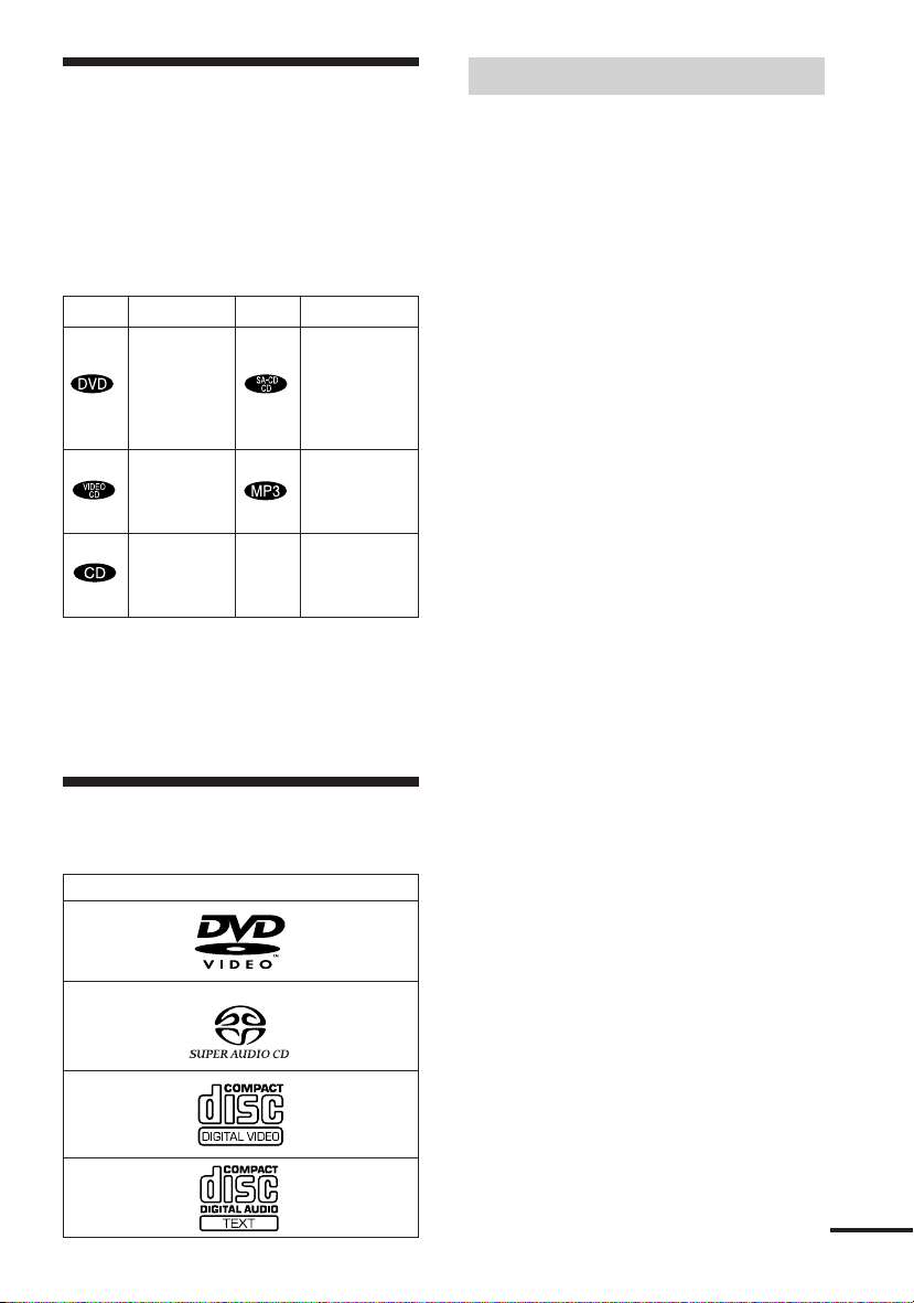
This system Can Play the Following Discs
Format of discs
DVD VIDEO
Terms for discs
• Title
The longest sections of a picture or music
feature on a DVD, movie, etc., in video
software, or the entire album in audio
software.
• Chapter
Sections of a picture or a music piece that
are smaller than titles. A title is composed
of several chapters. Depending on the disc,
no chapters may be recorded.
• Album
Section of a music piece on a data CD
containing MP3 audio tracks.
• Track
Sections of a picture or a music piece on a
VIDEO CD, Super Audio CD, CD, or
MP3.
• Index (Super Audio CD, CD) / Video
Index (VIDEO CD)
A number that divides a track into sections
to easily locate the point you want on a
VIDEO CD or Super Audio CD.
Depending on the disc, no indexes may be
recorded.
• Scene
On a VIDEO CD with PBC functions
(page 34), the menu screens, moving
pictures and still pictures are divided into
sections called “scenes.”
Super Audio CD
VIDEO CD
Music CD
The “DVD VIDEO” logo is a trademark.
continued
GB
7
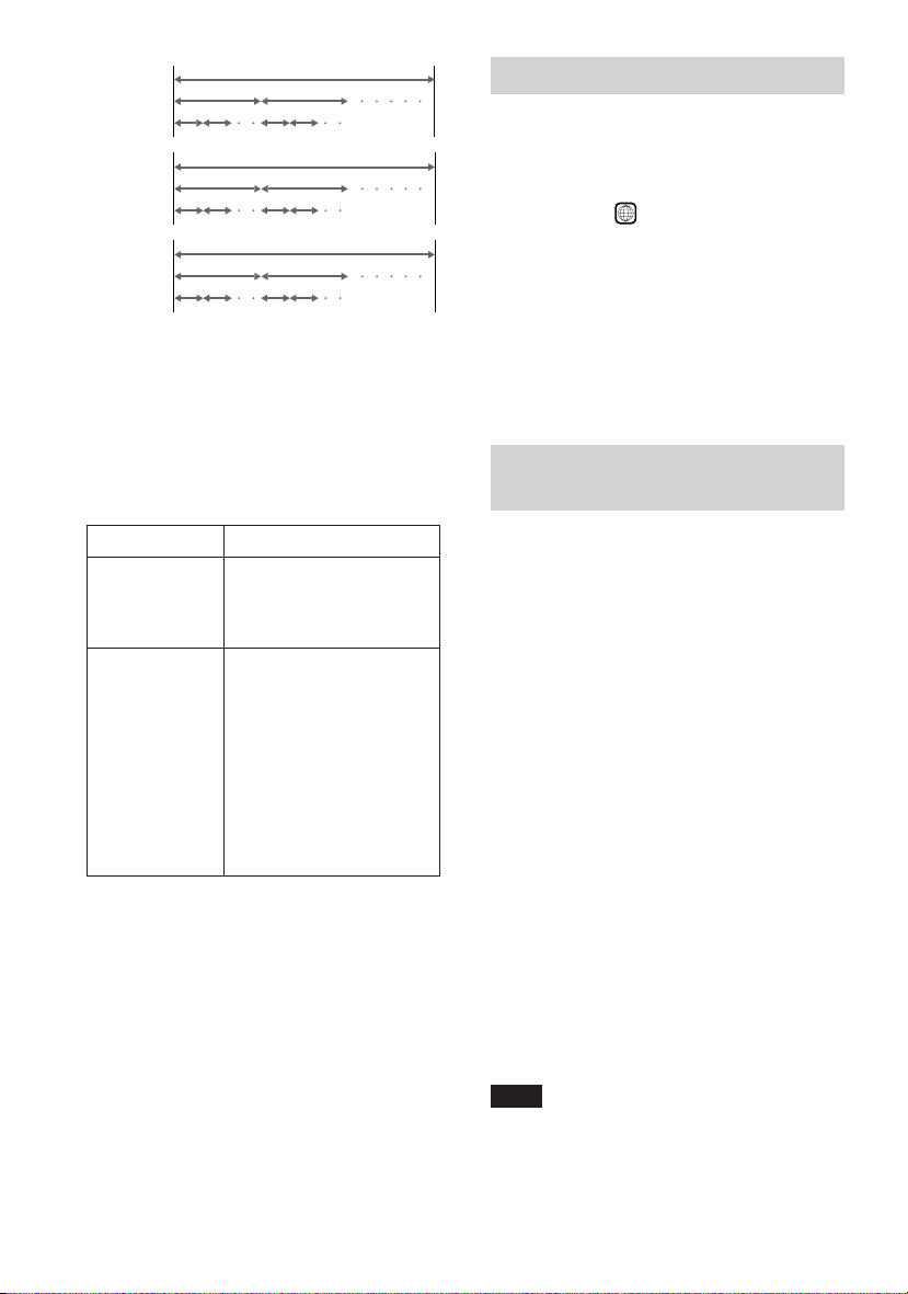
Disc
DVD
structure
VIDEO CD,
Super
Audio CD,
or CD
structure
MP3
structure
Title
Chapter
Tr ac k
Index
Album
Tr ac k
Disc
Disc
Note on PBC (Playback Control)
(VIDEO CDs)
This system conforms to Ver. 1.1 and Ver.
2.0 of VIDEO CD standards. You can enjoy
two kinds of playback depending on the disc
type.
Disc type
VIDEO CDs
without PBC
functions
(Ver. 1.1 discs)
VIDEO CDs
with PBC
functions
(Ver. 2.0 discs)
You can
Enjoy video playback
(moving pictures) as well
as music.
Play interactive software
using menu screens
displayed on the TV screen
(PBC Playback), in
addition to the video
playback functions of Ver.
1.1 discs. Moreover, you
can play high-resolution
still pictures, if they are
included on the disc.
Region code
Your system has a region code printed on
the back of the unit and will only play
DVDs labelled with the same region code.
ALL
DVDs labelled
will also play on this
system.
If you try to play any other DVD, the
message “Playback prohibited by area
limitations.” will appear on the TV screen.
Depending on the DVD, no region code
indication may be labelled even though
playing the DVD is prohibited by area
restrictions.
Examples of discs that the system
cannot play
The system cannot play the following discs:
• CD-ROMs (PHOTO CDs included)
• CD-Rs/CD-RWs other than those recorded
in the following formats:
– music CD format
– video CD format
– MP3 format that conforms to ISO9660*
Level 1/Level 2, or its extended format,
Joliet
• Data part of CD-Extras
•DVD-ROMs
•DVD Audio discs
*A logical format of files and folders on CD-ROMs,
defined by ISO (International Standard
Organization)
Do not load the following discs:
•A DVD with a different region code (page
8, 78).
•A disc that is neither standard nor circular
(e.g., card, heart, or star shape).
•A disc with paper or stickers on it.
•A disc that has the adhesive, cellophane
tape, or a sticker still left on it.
Note
Some CD-Rs or CD-RWs cannot be played on this
system depending upon the recording quality or
physical condition of the disc, or the characteristics
of the recording device.
Furthermore, the disc will not play if it has not been
GB
8
correctly finalized. For more information, see the
operating instructions for the recording device.
Note on playback operations of
DVDs and VIDEO CDs
Notes about the Discs
Some playback operations of DVDs and
VIDEO CDs may be intentionally set by
software producers. Since this system plays
DVDs and VIDEO CDs according to the
disc contents the software producers
designed, some playback features may not
be available. Also, refer to the instructions
supplied with the DVDs or VIDEO CDs.
Copyrights
This product incorporates copyright
protection technology that is protected by
method claims of certain U.S. patents, other
intellectual property rights owned by
Macrovision Corporation, and other rights
owners. Use of this copyright protection
technology must be authorized by
Macrovision Corporation, and is intended
for home and other limited viewing uses
only unless otherwise authorized by
Macrovision Corporation. Reverse
engineering or disassembly is prohibited.
This system incorporates with Dolby*
Digital and Dolby Pro Logic (II) adaptive
matrix surround decoder and the DTS**
Digital Surround System.
* Manufactured under license from Dolby
Laboratories.
“Dolby”, “Pro Logic” and the double-D symbol
are trademarks of Dolby Laboratories.
** Manufactured under license from Digital Theater
Systems, Inc.
“DTS” and “DTS Digital Surround” are
trademarks of Digital Theater Systems, Inc.
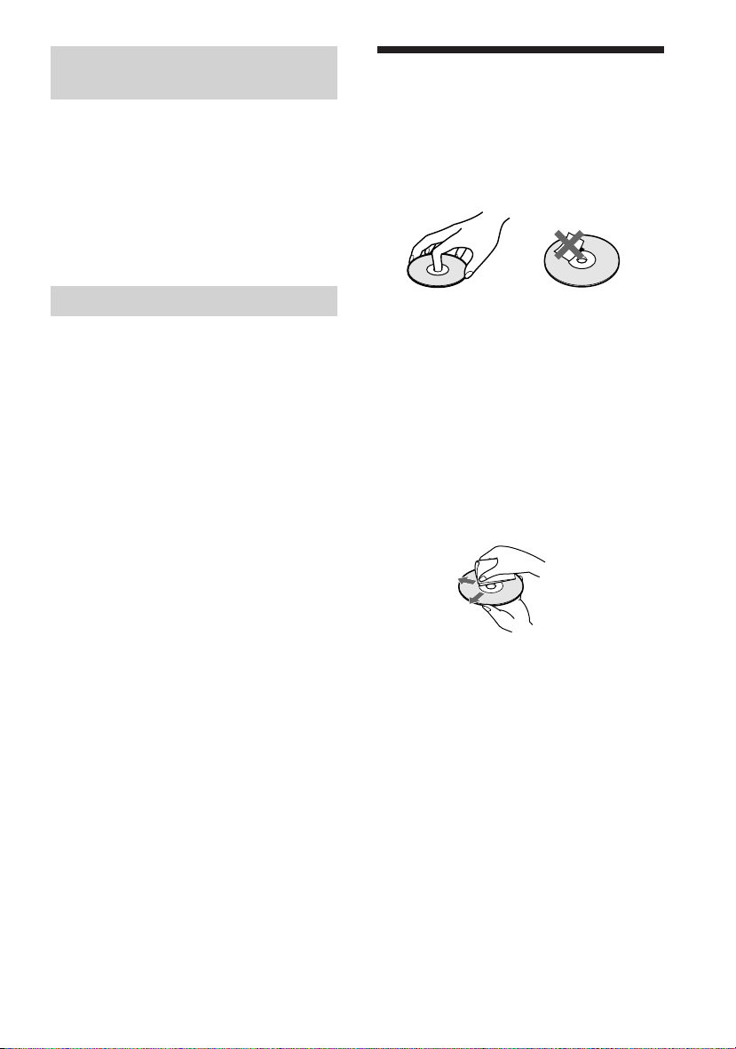
On handling discs
•To keep the disc clean, handle the disc by
its edge. Do not touch the surface.
• Do not stick paper or tape on the disc.
• Do not expose the disc to direct sunlight or
heat sources such as hot air ducts, or leave
it in a car parked in direct sunlight as the
temperature may rise considerably inside
the car.
• After playing, store the disc in its case.
On cleaning
• Before playing, clean the disc with a
cleaning cloth.
Wipe the disc from the center out.
• Do not use solvents such as benzine,
thinner, commercially available cleaners,
or anti-static spray intended for vinyl LPs.
This system can only play back a standard
circlar disc. Using neither standard nor
circular discs (e.g., card, heart, or star shape)
may cause a malfunction.
Do not use a disc that has a commercially
available accessory attached, such as a label
or ring.
GB
9
Index to Parts and Controls
For more information, refer to the pages indicated in parentheses.
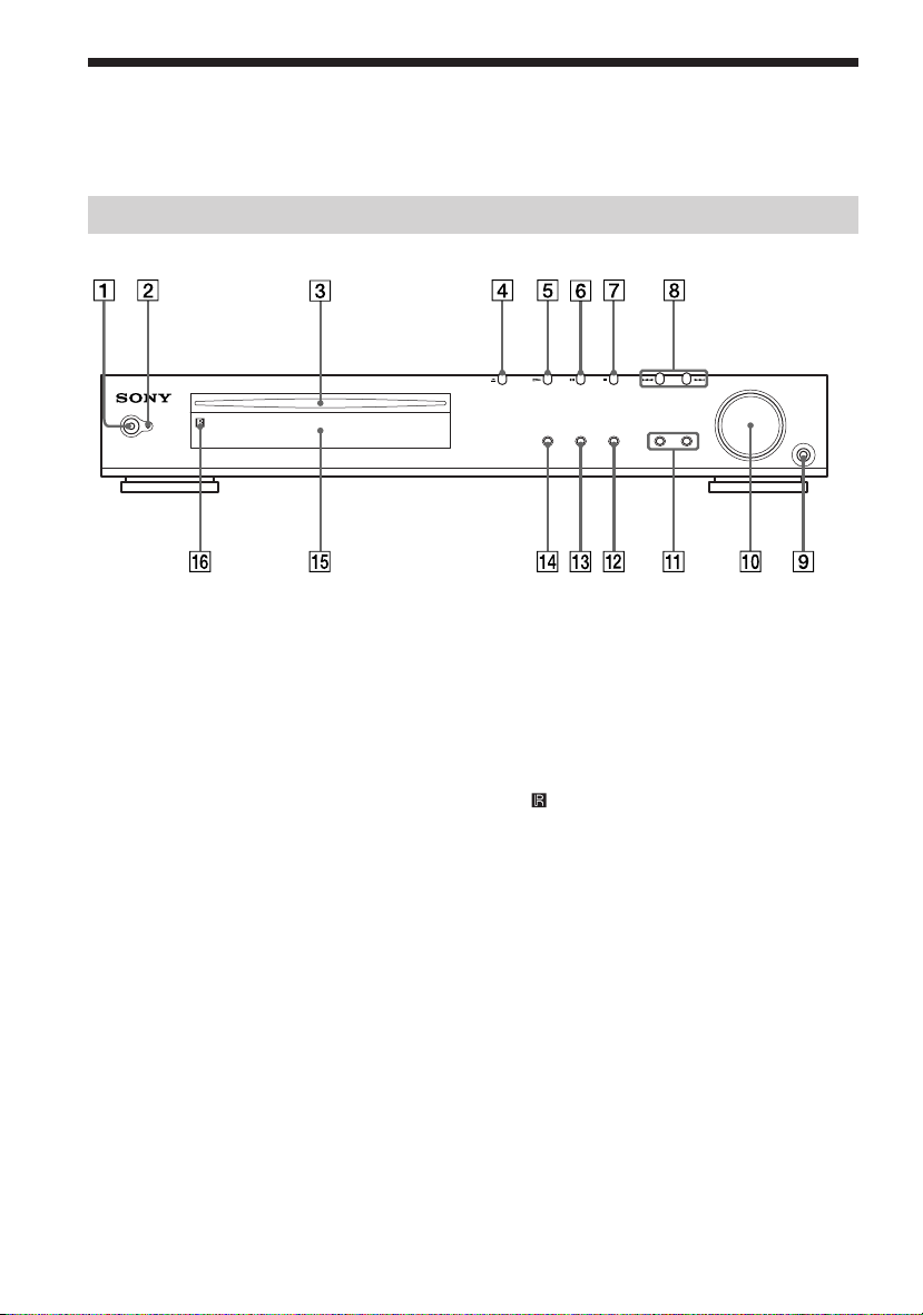
Front Panel
STANDBY
1 POWER switch (31)
2 STANDBY indicator (31)
3 Disc slot (31)
4 A (Eject) (31)
5 H (play) (31)
6 X (pause) (32)
7 x (stop) (30, 31)
8 ./> PREV/NEXT, PRESET –/+
(32, 61)
FUNCTION BAND DISPLAY SOUND FIELD
9 PHONES jack (31)
q; VOLUME control (31, 71)
qa SOUND FIELD –/+ (48, 51)
qs DISPLAY (61)
qd BAND (29)
qf FUNCTION (31, 60, 61)
qg Front panel display (11)
(remote sensor) (17)
qh
PHONES
10
GB
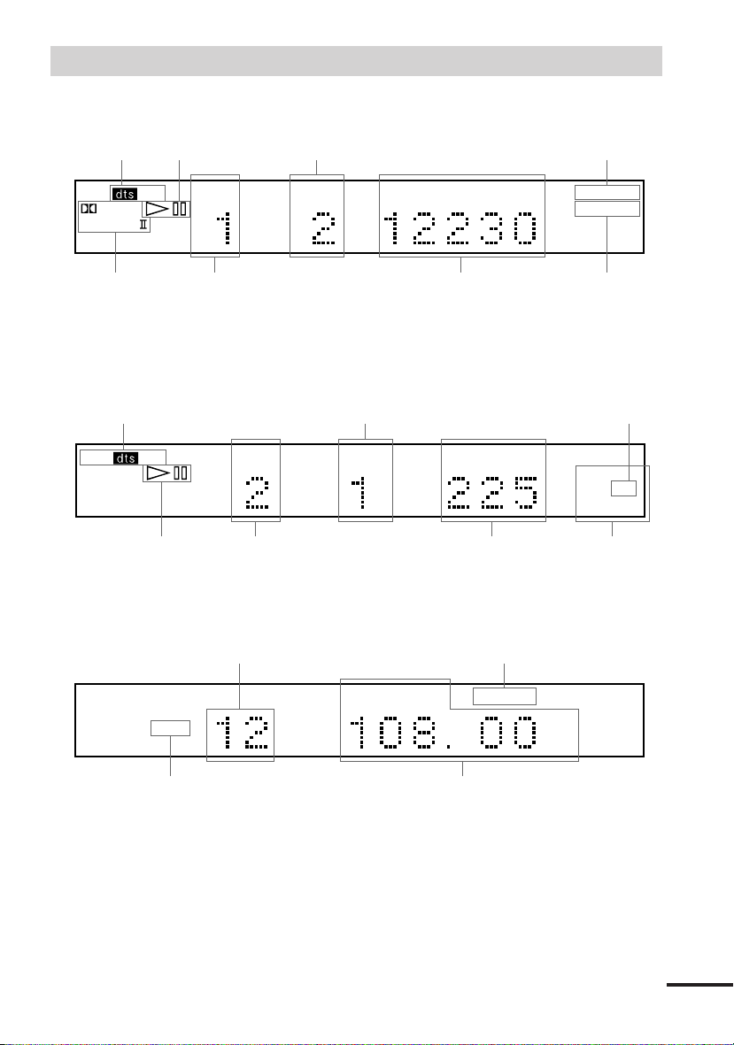
Front Panel Display
When playing back a DVD
Current sound
DIGITAL
PRO LOGIC
Current surround
format
Playing status
PCM
TITLE CHAPTER H M S
Current title
number
Current chapter number
Playing time Current repeat mode
When playing back a Super Audio CD, CD, VIDEO CD, or MP3
Current index number
(The index indicator does not appear
Current sound
SACD
PCM
Playing status
Current track number Current play mode
during Super Audio CD or MP3
playback.)
TRACK INDEX M S
Playing time
When listening to the radio
Lights up when you can
change the angle
ANGLE
REPEAT 1
Lights up during
PBC playback
(VIDEO CD only)
REPEAT 1
PROG PBC
SHUFFLE
FM AM
Current band
Preset number Monaural/Stereo effect
TUNED MONO ST
MHz
Current station
continued
11
GB
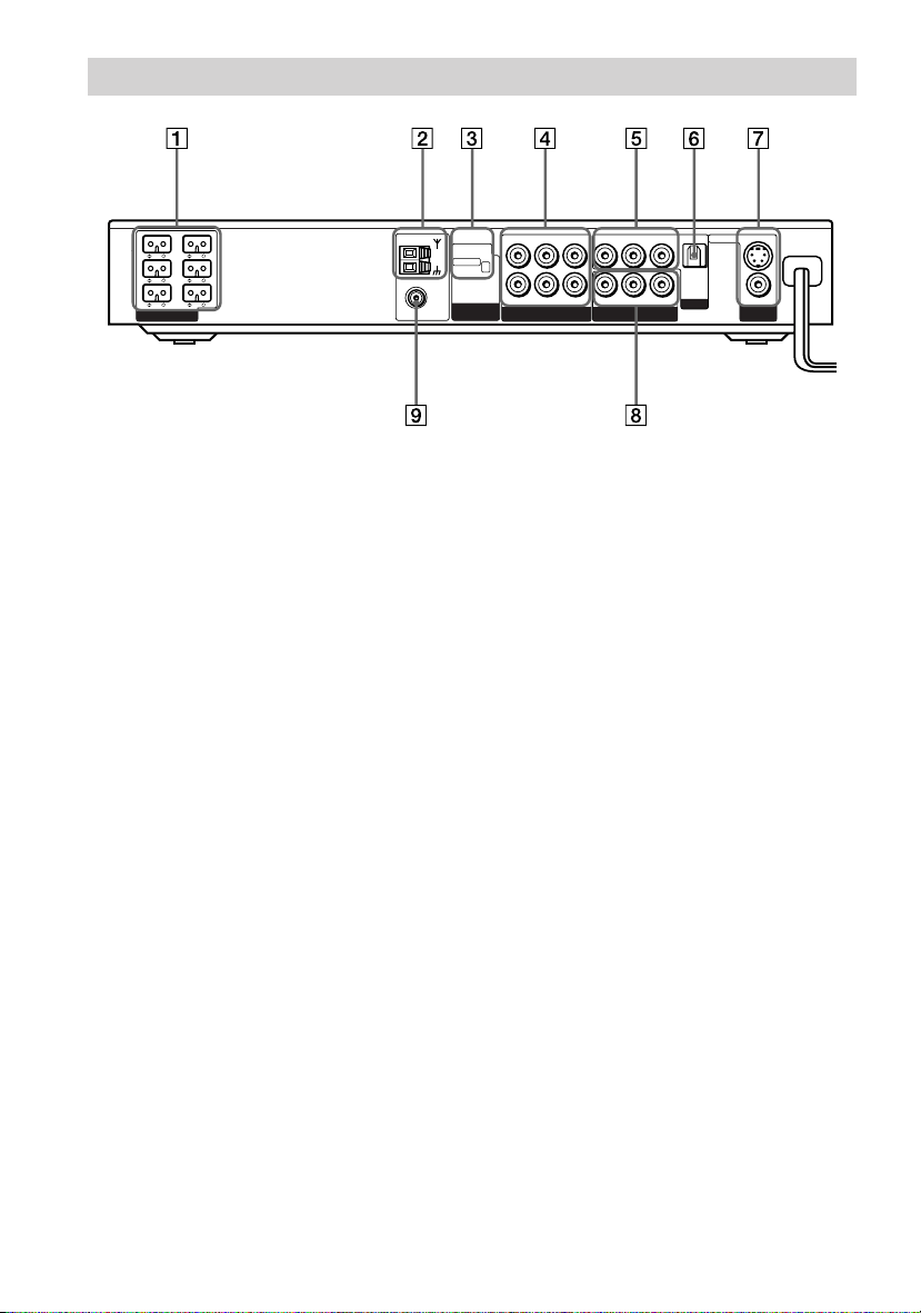
Rear Panel
FRONT
REAR
L
L
IMPEDANCE
USE
WOOFER 3Ω
EXCEPT
WOOFER 3Ω
FRONT
R
CENTER WOOFER
REAR
R
SPEAKER
1 SPEAKER jacks (18)
2 AM antenna (20)
3 COMPONENT VIDEO OUT/SCAN
SELECT switch (67, 72)
4 VIDEO 1 jacks (22)
5 VIDEO 2 jacks (22)
AM
COAXIAL
FM
75Ω
R
OPTICAL
DIGITAL
IN
VIDEO 2
S VIDEO (DVD ONLY)
MONITOR
SCAN SELECT
SELECTABLE
INTERLACE
COMPONENT
VIDEO OUT
AUDIO OUT
VIDEO OUT VIDEO IN
LR LR
LR
AUDIO IN VIDEO IN
VIDEO 1
AUDIO IN
YPB/CBPR/C
COMPONENT VIDEO OUT
6 DIGITAL IN (OPTICAL) jack (23)
7 MONITOR OUT (VIDEO/S VIDEO)
jacks (22)
8 COMPONENT VIDEO OUT jacks (22)
9 FM 75Ω COAXIAL antenna jack (20)
VIDEO
OUT
12
GB
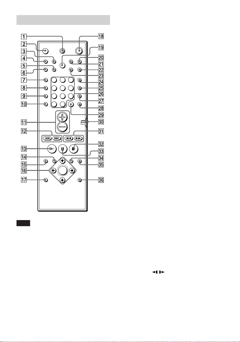
Remote
123
456
7
89
>
10
10/0
1 TV [/1 (on/standby) (59)
2 Z (EJECT) (31)
3 NAME (62)
4 STEREO/MONO (61)
5 MEMORY (29)
6 CLEAR (36, 38, 39, 41)
7 PLAY MODE (36, 38, 39)
8 AUDIO (46)
9 ANGLE (52)
q; SUBTITLE (53)
qa VOL +/– (59, 61)
qs ./> PREV/NEXT, TV CH –/+,
PRESET –/+ (29, 34, 59, 61)
qd H PLAY/SELECT (31, 34, 36, 38, 39,
40)
qf DVD TOP MENU (33)
qg DVD DISPLAY (35, 39, 41, 44, 46, 52,
53)
qh C/X/x/c/ENTER (25, 29, 33, 34, 36,
39, 41, 46, 51, 52, 53, 62)
qj DVD SETUP (55, 64)
qk 1 (standby) (29, 31, 61)
ql DIMMER (28)
w; TV/VIDEO (59)
wa REPEAT (36, 39)
ws MUTING (32)
wd TIME (43, 44)
wf FUNCTION (31, 60, 61, 62)
Note
This remote control glows in the dark. However,
before glowing, the remote must be exposed to light
for awhile.
wg BAND (29)
wh Number buttons (33, 34, 36, 41, 52, 59)
wj SOUND FIELD (48, 51)
wk DISPLAY (61)
wl ENTER (59)
e; COMMAND MODE DVD TV switch
(59)
ea m/M/
/ SLOW, TUNING –/+
(29, 40, 61)
es x STOP (31, 34, 54)
ed X PAUSE (32)
ef DVD MENU (33)
eg O RETURN (34, 35, 54)
eh AMP MENU (25, 51)
13
GB
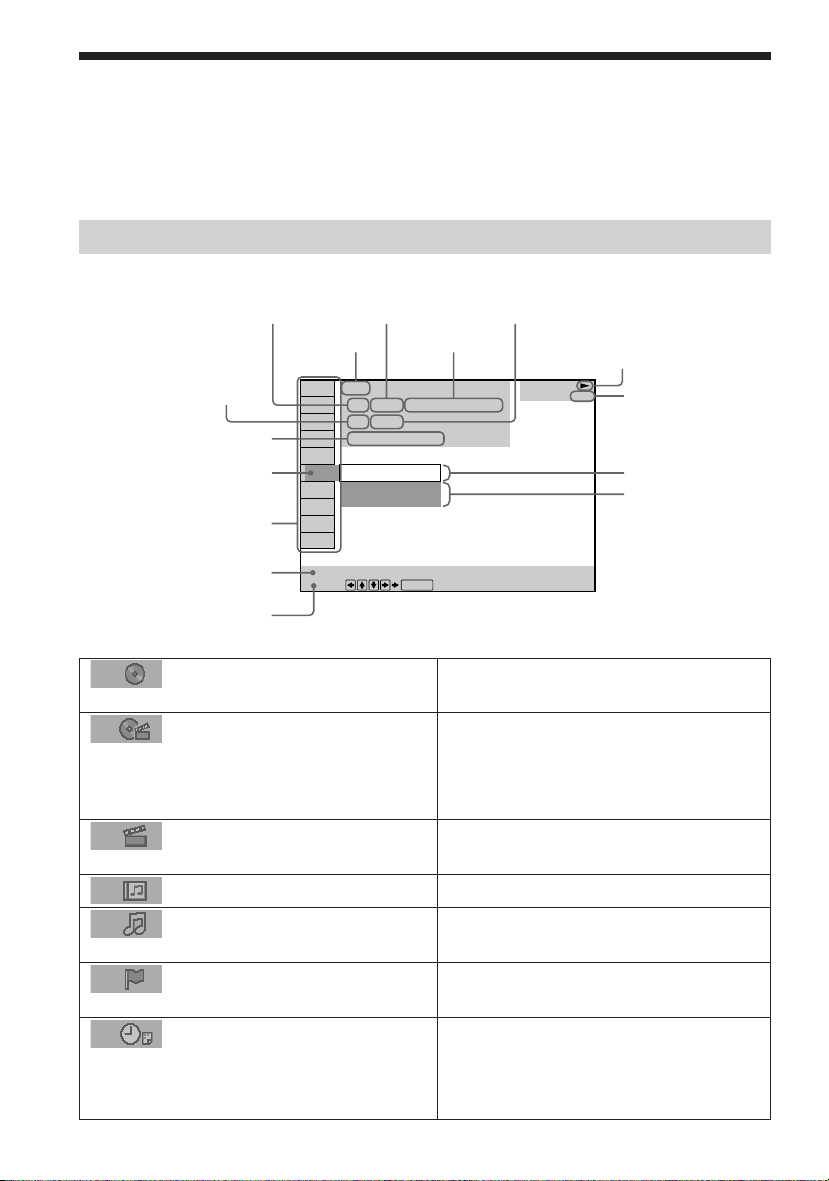
Guide to the Control Menu Display
Use the Control Menu to select a function that you’d like to use. The Control Menu display
appears when the DVD DISPLAY button is pressed. For details, refer to the page in
parentheses.
Control Menu
Total number of
Current playing title number (Video CD/
Super Audio CD/CD: track number)
Current playing chapter
number (Video CD/Super
Audio CD/CD: index number)
Playing time
Icon of selected
Control Menu item
Control Menu items
titles or tracks
recorded
Disc name or
disc type
DVD
1 2 ( 2 7 ) MAKING SCENE
1 8 ( 3 4
T
1: ENGLISH
2: FRENCH
3: SPANISH
Current playing
title name
)
1 : 3 2 : 5 5
Total number of chapters or indexes recorded
Playback status
(NPlayback, XPause, xStop, etc.)
DVD
Type of disc being
played back
Current setting
Options
Function name of selected
Control Menu item
Operation message
List of Control Menu Items
DISC
TITLE (DVD only) (page 41)/
SCENE (only VIDEO CD in PBC
playback) /TRACK (VIDEO CD
only) (page 41)
CHAPTER (DVD only) (page
42)/INDEX (VIDEO CD only) (page 42)
ALBUM (MP3 only) (page 35, 41)
TRACK (Super Audio CD/
CD/MP3 only) (page 35, 41)
INDEX (Super Audio CD/CD only)
(page 42)
TIME (page 42)
GB
14
SUBTITLE
Select:
ENTER
Displays the disc name or the disc type
inserted into the system.
Selects the title (DVD), the scene (VIDEO
CD in PBC playback), or the track
(VIDEO CD) to be played.
Selects the chapter (DVD) or the index
(VIDEO CD) to be played.
Selects the album (MP3) to be played.
Selects the track (Super Audio CD/CD/
MP3) to be played.
Displays the index and selects the index
(Super Audio CD) to be played.
Checks the elapsed time and the remaining
playback time.
Inputs the time code for picture and music
searching.
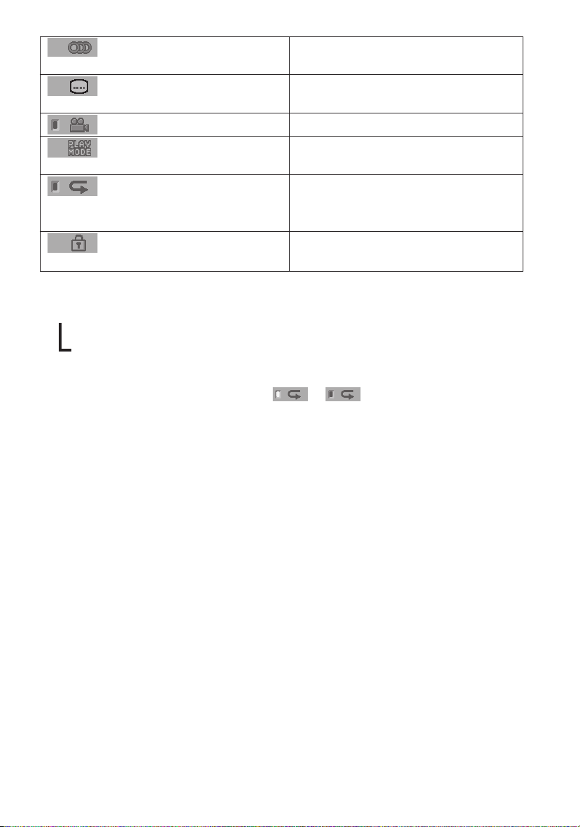
AUDIO (DVD/VIDEO CD/
Changes the audio setting.
Super Audio CD/CD only) (page 46)
SUBTITLE (DVD only) (page
53)
ANGLE (DVD only) (page 52)
PLAYMODE (VIDEO CD/
Displays the subtitles.
Changes the subtitle language.
Changes the angle.
Selects the play mode.
Super Audio CD/CD/MP3 only) (page 38)
REPEAT (page 39)
Plays the entire disc (all titles/all tracks),
one title/chapter/track/album, or contents
of program repeatedly.
CUSTOM PARENTAL
Sets the disc to prohibit playing.
CONTROL (page 54)
z Each time you press DVD DISPLAY, the Control Menu display changes as follows:
Control Menu display
,
m
Control Menu display off
The Control Menu items are different depending on the disc.
z The Control Menu icon indicator lights up in green t unless you set the REPEAT setting to
“OFF.”
The “ANGLE” indicator lights up in green only when the angles can be changed.
15
GB

Getting Started
Quick Overview
This chapter presents a quick overview so you can begin enjoying your new system right away.
For selecting a language used in the on-screen display, refer to the page 65.
For selecting the aspect ratio of the TV to be connected, refer to the page 66.
Unpacking
Check that you have the following items:
• Speakers (5)
• Subwoofer (1)
• AM loop antenna (1)
• FM wire antenna (1)
• Speaker cords (5m × 4, 15m × 2) (17ft. × 4, 50ft. × 2)
•Video cord (1)
• Remote Commander (remote) RM-SS880 (1)
• R6 (size AA) batteries (2)
•Foot pads (20)
• Speakers-connection and Installation (card) (1)
• 21-pin Adapter (1) (Only for the European models)
16
GB
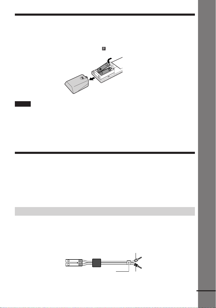
Inserting Batteries into the Remote
You can control the system using the supplied remote. Insert two R6 (size AA) batteries by
matching the 3 and # ends on the batteries to the markings inside the compartment. When
using the remote, point it at the remote sensor
on the system.
Notes
• Do not leave the remote in an extremely hot or humid place.
• Do not use a new battery with an old one.
• Do not drop any foreign object into the remote casing, particularly when replacing the batteries.
• Do not expose the remote sensor to direct light from the sun or lighting apparatus. Doing so may cause a
malfunction.
• If you do not use the remote for an extended period of time, remove the batteries to avoid possible damage from
battery leakage and corrosion.
Step 1: Speaker System Hookup
Getting Started
Connect the supplied speaker system using the supplied speaker cords by matching the colors
of the terminals to those of the cords. Do not connect any speakers other than those supplied
with this system.
To obtain the best possible surround sound, specify the speaker parameters (distance, level, etc.)
on page 25.
Required cords
Speaker cords
The connector and the color tube of the speaker cords are the same color as the label of the
terminals to be connected.
Grey
(+)
(–)
Color tube
(+)
(–)
Black
continued
17
GB
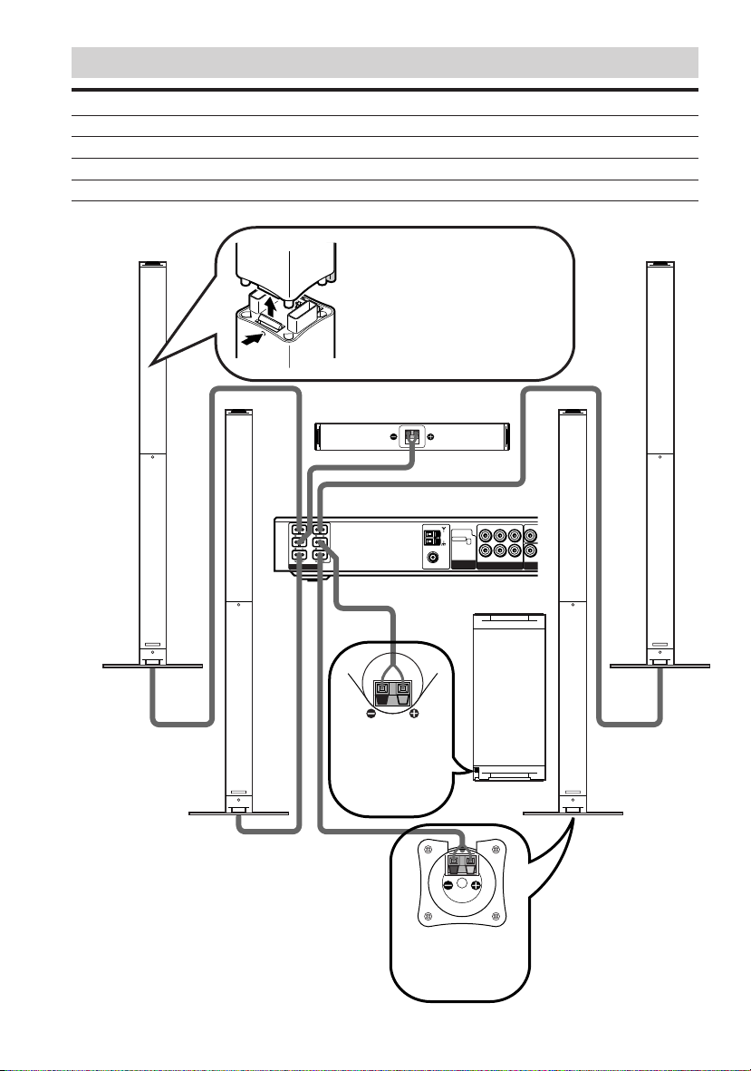
Terminals for connecting the speakers
Connect the To the
Front speakers SPEAKER FRONT L (white) and R (red) terminals
Rear speakers SPEAKER REAR L (blue) and R (grey) terminals
Center speaker SPEAKER CENTER (green) terminal
Subwoofer SPEAKER WOOFER (purple) terminal
Front speaker (R)
FRONT
R
CENTER WOOFER
REAR
R
SPEAKER
Attaching/detaching the speaker
sections
The front and rear speaker sections are
detachable. To attach, push the speaker
section onto the stand until it clicks into
place. To detach, push a pointed object,
such as a ballpoint pen, through the hole
and detach the speaker as illustrated.
Center speaker
AUDIO OUT
FRONT
L
REAR
L
AM
SELECTABLE
COAXIAL
FM
75Ω
VIDEO OUT AUDI
LRR
SCAN SELECT
INTERLACE
LR
AUDIO IN VIDEO IN
VIDEO 1
Y
COMPO
COMPONENT
VIDEO OUT
Tu r n over the
subwoofer to
connect the
speaker cord.
Subwoofer
Front speaker (L)
Note on placing speakers
Use caution when placing the subwoofer or
front/rear speakers on a specially treated
(waxed, oiled, polished, etc.) floor, as
staining or discoloration may result.
GB
18
Rear speaker (L)Rear speaker (R)
The bottom face of
each front and rear
speaker.
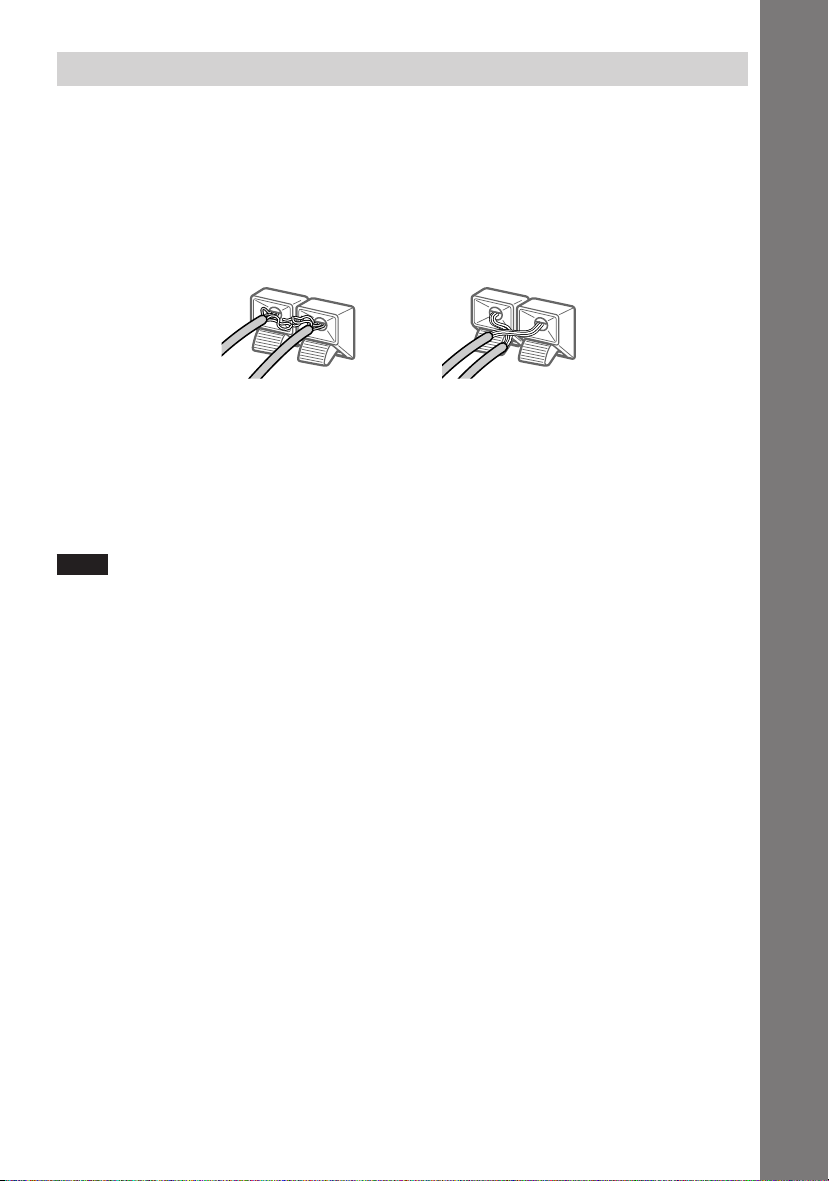
To avoid short-circuiting the speakers
Short-circuiting of the speakers may damage the system. To prevent this, be sure to follow these
precautions when connecting the speakers. Make sure the bare wire of each speaker cord does
not touch another speaker terminal or the bare wire of another speaker cord.
Examples of poor conditions of the speaker cord
Stripped speaker cord is
touching another speaker
terminal.
Stripped cords are touching
each other due to excessive
removal of insulation.
After connecting all the components, speakers, and AC power cord (mains lead), output a test
tone to check that all the speakers are connected correctly. For details on outputting a test tone,
see page 27.
If no sound is heard from a speaker while outputting a test tone, or a test tone is output from a
speaker other than the one currently displayed on the front panel display, the speaker may be
short-circuited. If this happens, check the speaker connection again.
Note
Be sure to match the speaker cord to the appropriate terminal on the components: 3 to 3, and # to #. If the
cords are reversed, the sound will be distorted and will lack bass.
Getting Started
19
GB
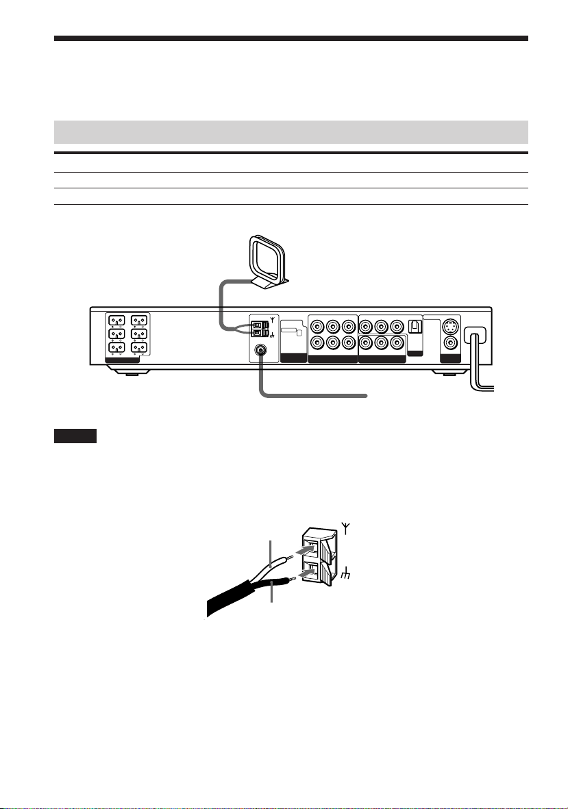
Step 2: Antenna Hookups
Connect the supplied AM/FM antennas for listening to the radio.
Terminals for connecting the antennas
Connect the To the
AM loop antenna AM terminals
FM wire antenna FM 75Ω COAXIAL terminal
AM loop antenna
OPTICAL
DIGITAL
IN
VIDEO 2
S VIDEO (DVD ONLY)
VIDEO
MONITOR
OUT
FRONT
R
CENTER WOOFER
REAR
R
FRONT
REAR
SPEAKER
AUDIO OUT
VIDEO OUT VIDEO IN
L
L
AM
COAXIAL
FM
75Ω
SCAN SELECT
SELECTABLE
INTERLACE
COMPONENT
VIDEO OUT
LR LR
LR
AUDIO IN VIDEO IN
VIDEO 1
AUDIO IN
YPB/CB PR/CR
COMPONENT VIDEO OUT
FM wire antenna
Notes
•To prevent noise pickup, keep the AM loop antenna away from the system and other components.
• Be sure to fully extend the FM wire antenna.
• After connecting the FM wire antenna, keep it as horizontal as possible.
• When you connect the supplied AM loop antenna, connect the black cord (B) to the U terminal, and the white
cord (A) to the other terminal.
A
AM
B
20
GB
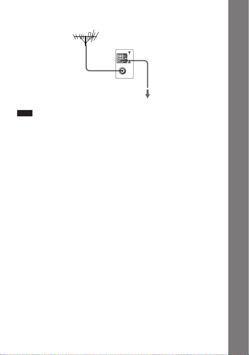
z If you have poor FM reception
Use a 75-ohms coaxial cable (not supplied) to connect the system to an outdoor FM antenna as shown below.
Outdoor FM antenna
System
COAXIAL
Earth wire
(not supplied)
AM
FM
75Ω
To ear th
Note
If you connect the system to an outdoor antenna, ground it to protect against lightning. To prevent a gas explosion,
do not connect the earth wire to a gas pipe.
Getting Started
21
GB
Step 3: TV and Video Component Hookups
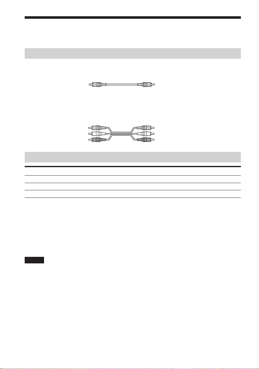
Required cords
Video cord for connecting a TV monitor
Yellow
Yellow
Audio/video cords (not supplied)
When connecting a cord, be sure to match the color-coded pins to the appropriate jacks on the
components.
Yellow (Video)
White (L/audio)
Red (R/audio)
Yellow (Video)
White (L/audio)
Red (R/audio)
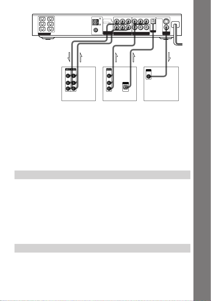
Jacks for connecting video components
Connect a To the
TV monitor MONITOR OUT jack
VCR VIDEO 1 jacks
Digital satellite receiver VIDEO 2 jacks
z When using the S video jack instead of the video jacks
Your TV monitor must also be connected via an S video jack. S video signals are on a separate bus from the video
signals and will not be output through the video jacks.
z When using the COMPONENT VIDEO OUT jacks (Y, PB/CB, PR/CR) instead of the video jacks
Your TV monitor must also be connected via COMPONENT VIDEO OUT jacks (Y, PB/CB, PR/CR). If your TV
accept progressive format signals, you must use this connection and set “COMPONENT OUT” to
“PROGRESSIVE” in “SCREEN SETUP” (page 67).
Notes
• When you select VIDEO 1 using the FUNCTION button, the signal is output from the front L/R speakers, but
not from the VIDEO 1 VIDEO OUT and AUDIO OUT L/R jacks.
• When you use the Video 1 line outputs, please set the unit to 2CH STEREO mode. If the unit is not in 2CH
STEREO mode, the line outputs may not function properly.
• When “PROGRESSIVE” is selected in “SCREEN SETUP,” no signal is output from the MONITOR OUT or S
VIDEO OUT jacks.
• When the mode of the system is set to “DVD,” the signal is output from the S VIDEO OUT or COMPONENT
OUT jacks.
• When the mode of the system is set to “DVD” and “PROGRESSIVE” is selected in “SCREEN SETUP,” the
signal is output only from the COMPONENT OUT jacks.
22
GB
FRONT
R
CENTER WOOFER
REAR
R
FRONT
REAR
SPEAKER
R
OPTICAL
DIGITAL
IN
VIDEO 2
S VIDEO (DVD ONLY)
VIDEO
MONITOR
OUT
AUDIO OUT
VIDEO OUT VIDEO IN
AUDIO IN
YPB/CBPR/C
COMPONENT VIDEO OUT
VIDEO OUT
LR LR
LR
AUDIO IN VIDEO IN
VIDEO 1
COAXIAL
AM
FM
75Ω
SCAN SELECT
SELECTABLE
INTERLACE
COMPONENT
L
L
Getting Started
IN INOUT OUT OUT
VIDEO
VIDEO
OUT
IN
AUDIO
AUDIO
OUT
IN
L
R
VIDEO
OUT
AUDIO
OUT
L
OUTPUT
R
OPTICAL
INPUT
VIDEO
IN
VCR Digital satellite receiver TV monitor
If you connect a digital satellite receiver with the OPTICAL jack
The digital satellite receiver can be connected to the OPTICAL jack instead of the VIDEO IN
and AUDIO IN L/R jacks of the system.
The system can accept both the digital and analog signals. Digital signals have priority over
analog signals. If the digital signal ceases, the analog signal will be processed after 2 seconds.
If you connect a digital satellite receiver without the OPTICAL jack
Connect the digital satellite receiver to the VIDEO IN and AUDIO IN L/R jacks only of the
system.
Setup for the system (for Asian and Australian models)
Setup is necessary for the system, depending on the TV monitor to be connected.
The initial setting for Asian models is NTSC but Australian models is PAL.
If the color system of the TV is PAL*
To set the system to PAL, turn on the system by pressing 1 (power) on the remote while
pressing X (pause) button on the system. You need to hold the X button until DAV-S880
appears on the display. To reset to NTSC, turn off the system and then turn on again using the
remote while pressing the X button on the system.
* If the color system of the TV is NTSC, do the same operation above to set the system to
NTSC.
Connecting the AC Power Cord (mains lead)
Before connecting the AC power cord (mains lead) of this system to a wall outlet (mains),
connect the speakers to the system (see page 17).
Connect the AC power cord (mains lead) of your TV/video components to a wall outlet (mains).
23
GB
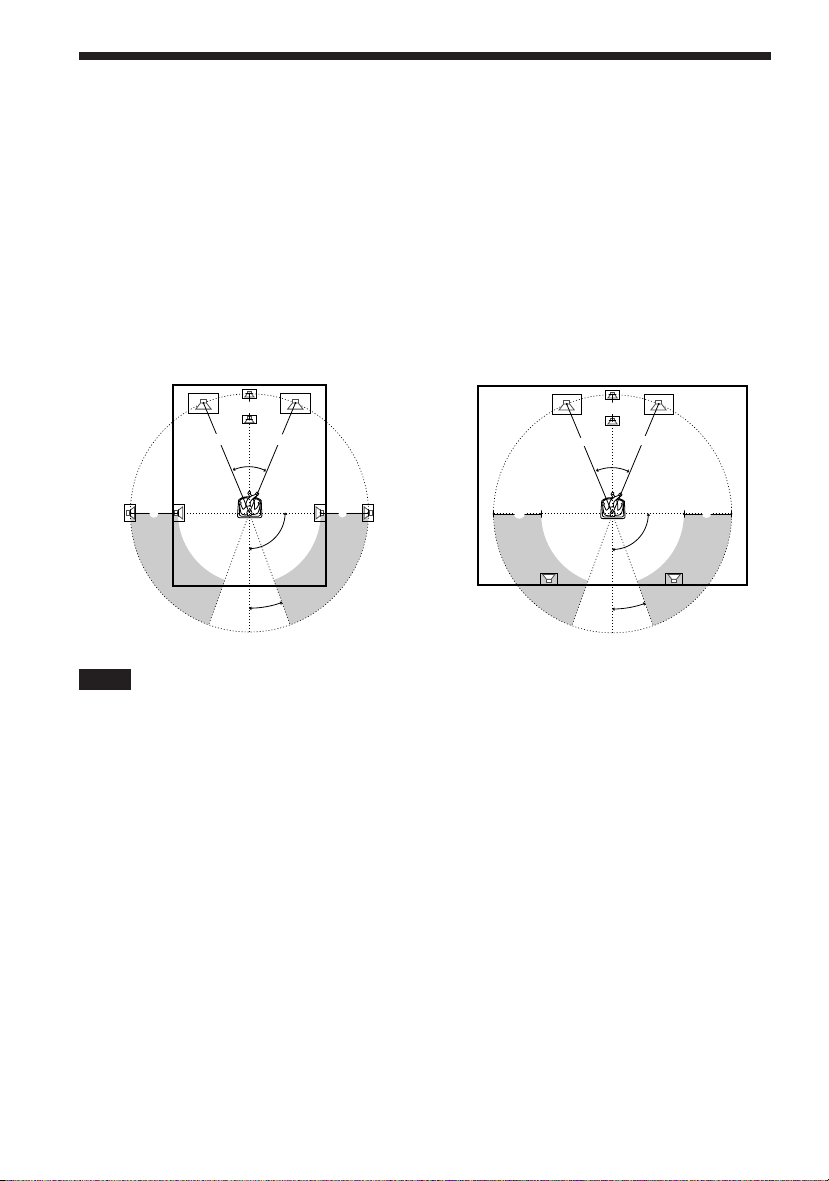
Speaker Setup
For the best possible surround sound, all the speakers other than the subwoofer should be the
same distance from the listening position (A).
However, this system allows you to place the center speaker up to 1.6 meters (5.0 feet) closer
(B) and the rear speakers up to 4.6 meters (15.0 feet) closer (C) to the listening position.
The front speakers can be placed from 1.0 to 15.0 meters (3.0 to 50.0 feet) (A) from the
listening position.
You can place the rear speakers either behind you or to the side, depending on the shape of your
room, etc.
When the rear speakers are placed to the side When the rear speakers are placed behind you
B
A A
45°
C
20°
C
90°
B
A A
45°
CC
90°
20°
Note
Do not place the center and rear speakers farther away from the listening position than the front speakers.
About magnetically shielded speaker (to prevent color irregularity occurring on
the TV screen)
The subwoofer in this system is magnetically shielded to prevent magnetic leakage. However,
some leakage may occur, as a high-strength magnet is employed. If the subwoofer is used with
a CRT-based TV or projector, install the subwoofer at least 0.3 meters (1.0 ft) from the TV set,
etc. If it is installed too close, color irregularity may occur on the screen.
If color irregularity occurs…
Turn off the TV set once, then turn it on after 15 to 30 minutes.
If color irregularity occurs again…
Place the subwoofer farther away from the TV set.
If color irregularity still occurs after performing the above…
Make sure that no magnetic object is nearby the subwoofer. Color irregularity may occur as a
result of interaction between the subwoofer and the magnetic object.
Examples of possible sources of magnetic interference include: magnetic latches on a TV stand,
etc., healthcare devices, toys, etc.
24
GB
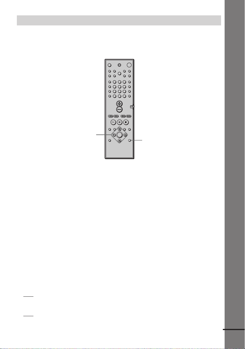
Specifying the speaker parameters
To obtain the best possible surround sound, first specify the distance of the speakers from your
listening position, then set the balance and level. Use the test tone to adjust the speaker volumes
to the same level.
You may adjust the speaker parameters using SPEAKER SETUP in the setup display (page 69).
123
456
7
89
>
10
10/0
Getting Started
C/X/x/c/ENTER
AMP MENU
To specify the size, distance, position and height of the speakers
1 Press AMP MENU repeatedly to display 9 SP. SETUP on the front panel display.
2 Sit in your listening position and select the item to be set using X/x.
• Items set in 9 SP. SETUP
– Size of the rear and center speakers
– Distance of the front, rear, and center speakers
–Position and height of the rear speakers
3 Set the parameter using C/c.
The selected parameter will appear on the front panel display.
4 Repeat Steps 2 and 3 to set other parameters in 9 SP. SETUP.
If you do not operate the remote for a few seconds, the parameter disappears from the
display and is stored in the system.
xSIZE
When you do not connect center or rear speakers, or move the rear speakers, set the parameters
for CENTER and REAR. Since the front speaker and subwoofer settings are fixed, you cannot
change them. The default settings are underlined.
• CENTER (center speaker)
YES: Normally select this.
–
– NO: Select this if no center speaker is used.
• REAR (rear speakers)
YES: Normally select this. Specify the position and height to implement the Digital Cinema
–
Surround modes.
– NO: Select this if no rear speaker is used.
continued
25
GB
xDISTANCE
You can vary the distance of each speaker as follows. The default settings are underlined.
•F. D.
5 m (17 ft) (front speakers distance)
Front speaker distance can be set in 0.2 meters (1.0 foot) steps from 1.0 to 15.0 meters (3.0 to
50.0 feet).
5 m (17 ft) (center speaker distance)
• C. D.
Center speaker distance can be set in 0.2 meters (1.0 foot) steps from a distance equal to the
front speaker distance to a distance 1.6 meters (5.0 feet) closer to your listening position.
3.4 m (12 ft) (rear speakers distance)
• R. D.
Rear speaker distance can be set in 0.2 meters (1.0 foot) steps from a distance equal to the
front speaker distance to a distance 4.6 meters (15.0 feet) closer to your listening position.
Notes
• If each of the front or rear speakers are not placed an equal distance from your listening position, set the distance
of the closest speaker.
• In SPEAKER SETUP, the North American model’s OSD displays both metric and imperial measurements. The
other model's displays metric measurements only. The manual shows both.
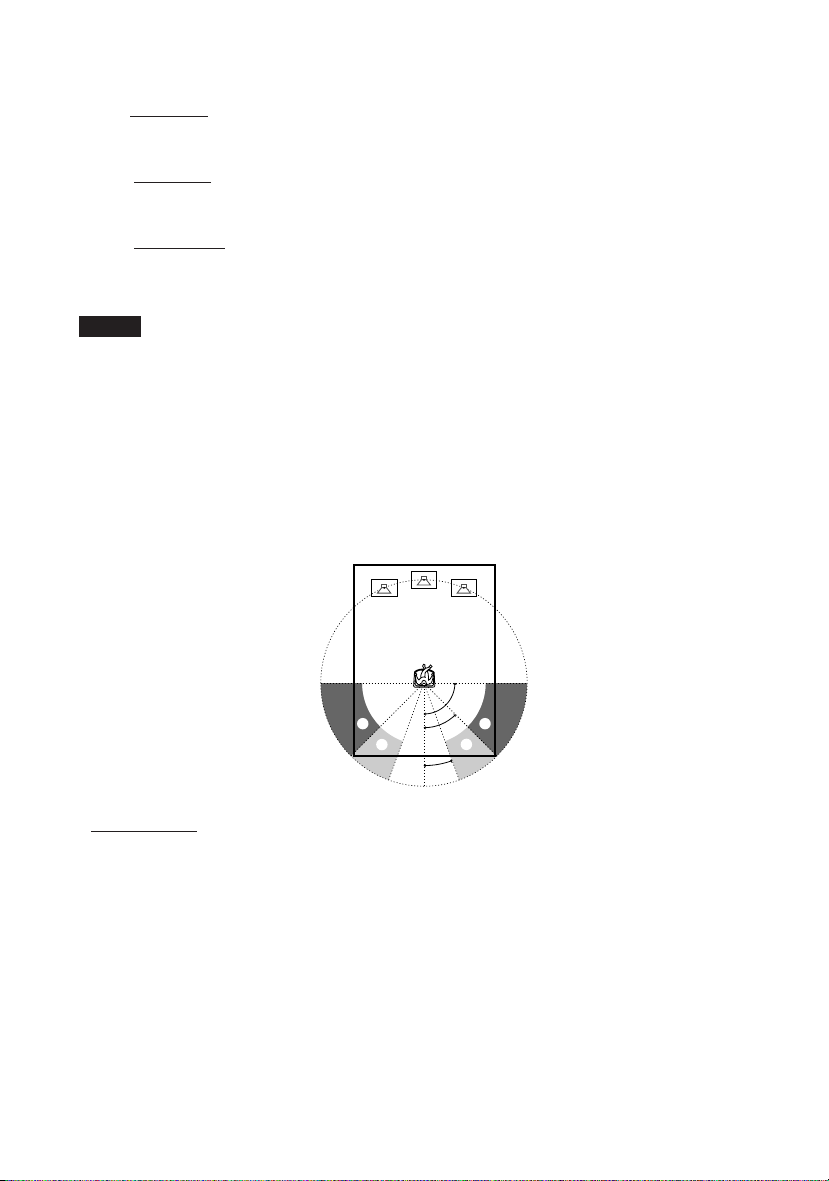
Specifying the rear speaker position and height
If you select anything other than “NO” in “REAR,” specify the position and height of the rear
speakers. The default settings are underlined.
Position diagram
• R. P. BEHIND
Select this if the rear speakers are located in the section B.
• R. P. SIDE
Select this if the rear speakers are located in the section A.
GB
26
90
AA
45
BB
20
 Loading...