

2-591-181-12(1)
DVD Home Theatre
System
Operating Instructions
DAV-LF10
©2005 Sony Corporation
3
WARNING
To prevent fire or shock hazard, do not
expose the unit to rain or moisture.
Caution – The use of optical instruments
with this product will increase eye
hazard.
For the customers in the U.S.A
This symbol is intended to alert the user to
the presence of uninsulated “dangerous
voltage” within the product’s enclosure that
may be of sufficient magnitude to constitute a risk of
electric shock to persons.
This symbol is intended to alert the user to
the presence of important operating and
maintenance (servicing) instructions in the
literature accompanying the appliance.
Owner’s Record
The model and serial numbers are located at the rear of
the unit. Record the serial number in the space
provided below. Refer to them whenever you call upon
your Sony dealer regarding this product.
Model No. DAV-LF10
Serial No.______________
WARNING
This equipment has been tested and found to comply
with the limits for a Class B digital device, pursuant to
Part 15 of the FCC Rules. These limits are designed to
provide reasonable protection against harmful
interference in a residential installation. This
equipment generates, uses, and can radiate radio
frequency energy and, if not installed and used in
accordance with the instructions, may cause harmful
interference to radio communications. However, there
is no guarantee that interference will not occur in a
particular installation. If this equipment does cause
harmful interference to radio or television reception,
which can be determined by turning the equipment off
and on, the user is encouraged to try to correct the
interference by one or more of the following measures:
– Reorient or relocate the receiving antenna.
– Increase the separation between the equipment and
receiver.
– Connect the equipment into an outlet on a circuit
different from that to which the receiver is
connected.
– Consult the dealer or an experienced radio/TV
technician for help.
CAUTION
You are cautioned that any changes or modifications
not expressly approved in this manual could void your
authority to operate this equipment.
Note to CATV system installer:
This reminder is provided to call the CATV system
installer’s attention to Article 820-40 of the NEC that
provides guidelines for proper grounding and, in
particular, specifies that the cable ground shall be
connected to the grounding system of the building, as
close to the point of cable entry as practical.
For the customers in Canada
CAUTION
TO PREVENT ELECTRIC SHOCK, MATCH WIDE
BLADE OF PLUG TO WIDE SLOT, FULLY
INSERT.
Except for North American
models
Do not install the appliance in a confined space, such
as a bookcase or built-in cabinet.
To prevent fire, do not cover the ventilation of the
apparatus with news papers, table-cloths, curtains, etc.
And don’t place lighted candles on the apparatus.
To prevent fire or shock hazard, do not place objects
filled with liquids, such as vases, on the apparatus.
Don’t throw away the battery with
general house waste, dispose of it
correctly as chemical waste.
This appliance is
classified as a CLASS 1
LASER product. The
label is located on the
rear of the control unit.
GB
2

Precautions
Safety
• If anything falls into the cabinet, unplug the unit and
have it checked by qualified personnel before
operating it any further.
• The unit is not disconnected from the AC power
source (mains) as long as it is connected to the wall
outlet (mains), even if the unit itself has been turned
off.
• Unplug the unit from the wall outlet if you do not
intend to use it for an extended period of time. To
disconnect the cord, pull it out by the plug, never by
the cord.
Installing
• Allow adequate air circulation to prevent internal
heat build-up.
• Do not place the unit on surfaces (rugs, blankets, etc.)
or near materials (curtains, draperies) that may block
the ventilation slots.
• Do not install the unit near heat sources such as
radiators, or air ducts, or in a place subject to direct
sunlight, excessive dust, mechanical vibration, or
shock.
• Do not install the unit in an inclined position. It is
designed to be operated in a horizontal position only.
• Keep the unit and discs away from equipment with
strong magnets, such as microwave ovens, or large
loudspeakers.
• Do not place heavy objects on the unit.
• If the unit is brought directly from a cold to a warm
location, moisture may condense inside the DVD
Home Theatre System and cause damage to the
lenses. When you first install the unit, or when you
move it from a cold to a warm location, wait for about
30 minutes before operating the unit.
®
ENERGY STAR
registered mark.
As an ENERGY STAR
Sony Corporation has determined
that this product meets the
ENERGY STAR
energy efficiency.
is a U.S.
®
partner,
®
guidelines for
Welcome!
Thank you for purchasing Sony DVD Home
Theatre System. Before operating this system,
please read this manual thoroughly and retain it
for future reference.
Precautions
On power sources
AC power cord (mains lead) must be changed only at
the qualified service shop.
On placement
• Place the system in a location with adequate
ventilation to prevent heat build-up in the system.
• At high volum e, over long periods of time, the cabinet
becomes hot to the touch. This is not a malfunction.
However, touching the cabinet shoul d be avoided. Do
not place the unit in a confined space where
ventilation is poor as this may cause overheating.
• Do not block the cooling fan or ventilation slots by
putting anything on the system. The system is
equipped with a high power amplifier. If the cooling
fan or ventilation slots are blocked, the unit can
overheat and malfunction.
• Do not place the system in a location near heat
sources, or in a place subject to direct sunlight,
excessive dust, or mechanical shock.
• Do not place anything around the rear of the
subwoofer as air pressure from the subwoofer’s duct
may knock it down.
• Do not insert anything into the rear openings of the
control unit or subwoofer. This may cause electric
shock or injury.
• Do not insert anything into the subwoofer’s duct, as
sound quality may be affected.
• Do not use the speaker as a footstool. The speaker
may fall down or break, causing injury.
On operation
• If the system is brought directly from a cold to a warm
location, or is placed in a very damp room, moisture
may condense on the lenses inside the system. Should
this occur, the system may not operate properly. In
this case, remove the disc and leave the system turned
on for about half an hour until the moisture
evaporates.
• When you move the system, take out any disc. If you
don’t, the disc may be damaged.
continued
GB
3

• For power saving purposes, set the system to standby
mode by pressing the "/1 button (the standby
indicator lights up). To turn off the system
completely, remove the AC power cord (mains lead)
from the wall outlet (mains).
• Do not carry the system while it is turned on.
On adjusting volume
Do not turn up the volume while listening to a section
with very low level inputs or no audio signals. If you
do, the speakers may be damaged when a peak level
section is suddenly played.
On cleaning
Clean the cabinet, panel, and controls with a soft cloth
slightly moistened with a mild detergent solution. Do
not use any type of abrasive pad, scouring powder or
solvent such as alcohol or benzine.
If you have any ques tions or problems concerning your
system, please consult your nearest Sony dealer.
On cleaning discs
Do not use a commercially available CD/DVD
cleaning disc. It may cause a malfunction.
On your TV’s color
If the speakers should cause the TV screen to have
color irregularity, turn off the TV at once then turn it
on after 15 to 30 minutes. If color irregularity should
persist, place the speakers farther away from the set.
3 Touch the Touch Panel Sensor .
(page 43) and Z of the control unit
simultaneously for a few seconds until the
front panel display changes to “Mecha
Lock.” If some messages other than “Mecha
Lock” appear, ignore them.
To cancel, press "/1.
4 Remove the AC power cord (mains lead)
from the wall outlet (mains).
Note
Do not handle the clear plastic panel when you move
or operate the control unit as it may break.
The nameplate is located on the rear of the unit.
IMPORTANT NOTICE
Caution: This system is capable of holding a still
video image or on-screen display image on your
television screen indefinitely. If you leave the still
video image or on-screen display image displayed
on your TV for an extended period of time you risk
permanent damage to your television screen.
Projection televisions are especially susceptible to
this.
On moving the system
When you carry the system, use the following
procedure to protect the inner mechanism.
1 Make sure that a disc is removed from the
system.
2 Press FUNCTION on the remote or touch
the Touch Panel (page 43) repeatedly to
select “DVD.”
GB
4

Table of Contents
Welcome!................................................3
Precautions..............................................3
About This Manual .................................7
This System Can Play the Following
Discs .................................................7
Notes about Discs ...................................9
Guide to the Control Menu Display......10
Getting Started
Unpacking.............................................12
Using the Remote..................................13
Step 1: Speaker System Hookup........... 15
Step 2: Antenna (Aerial) Hookups........ 22
Step 3: TV and Video Component
Hookups..........................................24
Step 4: Connecting the AC Power Cords
(Mains Leads) and Powering On ....29
Step 5: Adjusting the Wireless
System ............................................30
Step 6: Performing the Quick Setup ..... 34
Speaker Setup........................................ 36
Playing Discs
Playing Discs ........................................41
Operating by the
Touch Panel Sensor ........................43
Resuming Playback from the Point Where
You Stopped the Disc .....................44
(Resume Play)
Using the DVD’s Menu ........................ 45
Selecting [ORIGINAL] or [PLAY LIST]
on a DVD-RW Disc........................45
Playing VIDEO CDs with PBC Functions
(Ver. 2.0).........................................46
(PBC Playback)
Playing an MP3 Audio Track ...............47
Playing JPEG Image Files .................... 48
Creating Your Own Program ................51
(Program Play)
Playing in Random Order .....................52
(Shuffle Play)
Playing Repeatedly ...............................53
(Repeat Play)
Searching for a Particular Point on
a Disc.............................................. 54
(Scan, Slow-motion Play)
Searching for a Title/Chapter/Track/
Index/Album/File........................... 55
Viewing Disc Information.................... 57
Sound Adjustments
Changing the Sound.............................. 62
Enjoying Surround Sound .................... 64
Enjoying TV or VCR Sound from All
Speakers ......................................... 69
Using the Sound Effect......................... 69
Using Various Additional
Functions
Changing the Angles ............................ 70
Displaying Subtitles.............................. 71
Locking Discs....................................... 72
(CUSTOM PARENTAL
CONTROL, PARENTAL
CONTROL)
Other Operations
Controlling TV with the Supplied
Remote ........................................... 77
Using the SONY TV DIRECT
(THEATRE SYNC) Function ........ 79
Using the Video or Other Units............ 81
Enjoying Multiplex Broadcast Sound
(Dual Mono)................................... 81
Enjoying the Radio............................... 82
Using the Sleep Timer .......................... 85
Changing the Brightness of the Front
Panel Display.................................. 86
Returning to the Default Settings ......... 86
continued
GB
5

Settings and Adjustments
Using the Setup Display........................87
Setting the Display or Sound Track
Language ........................................88
(LANGUAGE SETUP)
Settings for the Display.........................88
(SCREEN SETUP)
Custom Settings ....................................90
(CUSTOM SETUP)
Settings for the Speakers.......................92
(SPEAKER SETUP)
Quick Setup and Resetting the
System ............................................97
(SETUP)
Additional Information
Troubleshooting....................................98
Specifications......................................101
Glossary .............................................. 103
Index to Parts and Controls.................107
Language Code List ............................113
DVD Setup Menu List ........................114
AMP Menu List ..................................116
Index ...................................................117
GB
6
About This Manual
• The OSD (on-screen display) may vary
depending on the country model.
• The instructions in this manual describe the
controls on the remote. You can also use the
controls on the system if they have the same or
similar names as those on the remote.
• Measurements are expressed in feet (ft) for
North American models.
• The following symbols are used in this
manual.
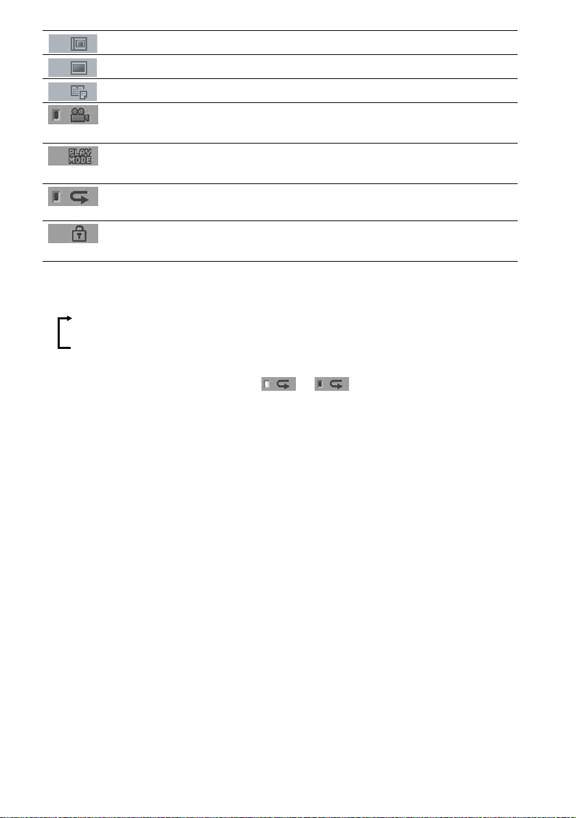
Symbol Meaning
Functions available for DVD
VIDEOs, DVD-Rs/DVD-RWs, and
DVD+Rs/DVD+RWs
Functions available for DVD-RWs
in VR (Video Recording) mode
Functions available in VIDEO CD
mode
Functions available in CD mode
Functions available in Super Audio
CD and Audio CD mode
Functions available for MP3* audio
tracks
Functions available for JPEG files
* MP3 (MPEG1 Audio Layer 3) is a standard format
defined by ISO/MPEG which compresses audio data.
This System Can Play the Following Discs
Format of
discs
Audio CD
CD-R/CD-RW
(audio data)
(MP3 files)
(JPEG files)
The “DVD VIDEO” logo is a trademark.
Disc logo
Note on PBC (Playback
Control) (VIDEO CDs)
This system conforms to Ver. 1.1 and Ver. 2.0 of
VIDEO CD standards. You can enjoy two kinds
of playback depending on the disc type.
Disc type You can
VIDEO CDs
without PBC
functions
(Ver. 1.1 discs)
VIDEO CDs
with PBC
functions
(Ver. 2.0 discs)
Enjoy video playback (moving
pictures) as well as music.
Play interactive software using
menu screens displayed on the
TV screen (PBC Playback), in
addition to the video playback
functions of Ver. 1.1 discs.
Moreover, you can play highresolution still pictures, if they
are included on the disc.
Format of
discs
DVD VIDEO
Super Audio
CD
VIDEO CD
Disc logo
About Multi Session CD
• This system can play Multi Session CDs when
an MP3 audio track is contained in the first
session. Any subsequent MP3 audio tracks
recorded in later sessions can also be played
back.
• This system can play Multi Session CDs when
a JPEG image file is contained in the first
session. Any subsequent JPEG image files
recorded in later sessions can also be played
back.
continued
GB
7

• If audio tracks and images in music CD format
or video CD format are recorded in the first
session, only the first session will be played
back.
Region code
Your system has a region code printed on the
back of the unit and will only play DVDs labeled
with the same region code.
DVDs labeled will also play on this system.
If you try to play any other DVD, the message
[Playback prohibited by area limitations.] will
appear on the TV screen. Depending on the
DVD, no region code indication may be given
even though playing the DVD is prohibited by
area restrictions.
ALL
Notes about CD-R/CD-RW/
DVD-R/DVD-RW/DVD+R/
DVD+RW
In some cases, CD-R/CD-RW/DVD-R/DVDRW/DVD+R/DVD+RW cannot be played on
this player due to the recording quality or
physical condition of the disc, or the
characteristics of the recording device and
authoring software.
The disc will not play if it has not been correctly
finalized. For more information, see the
operating instructions for the recording device.
Note that discs created in the Packet Write
format cannot be played.
Music discs encoded with
copyright protection
Examples of discs that the
system cannot play
The system cannot play the following discs:
• CD-ROMs (except for extension “.MP3,”
“.JPG,” or “.JPEG”)
• CD-Rs/CD-RWs other than those recorded in
the following formats:
– audio CD format
– video CD format
– MP3/JPEG format that conforms to
ISO9660* Level 1/Level 2, or its extended
format, Joliet
• Data part of CD-Extras
•DVD-ROMs
• DVD Audio discs
•DVD-RAMs
• Progressive JPEG file
* A logical format of files and folders on CD-ROMs,
defined by ISO (International Organization for
standardization)
Do not load the following discs:
• A DVD with a different region code (page 8,
105).
• A disc that is neither standard nor circular
(e.g., card, heart, or star shape).
• A disc with paper or stickers on it.
• A disc that has adhesive or cellophane tape still
left on it.
GB
8
technologies
This product is designed to playback discs that
conform to the Compact Disc (CD) standard.
Recently, various music discs encoded with
copyright protection technologies are marketed
by some record companies. Please be aware that
among those discs, there are some that do not
conform to the CD standard and may not be
playable by this product.
Note on DualDiscs
This product is designed to playback discs that
conform to the Compact Disc (CD) standard. A
DualDisc is a two sided disc product which
mates DVD recorded material on one side with
digital audio material on the other side. Please
be aware that the audio side of a DualDisc may
not play on this product because these discs do
not conform to the CD standard.
“DualDisc” is a trademark of the Recording
Industry Association of America (RIAA).
Note on playback operations
of DVDs and VIDEO CDs
Some playback operations of DVDs and VIDEO
CDs may be intentionally set by software
producers. Since this system plays DVDs and
VIDEO CDs according to the disc contents the
software producers designed, some playback
features may not be available. Also, refer to the
instructions supplied with the DVDs or VIDEO
CDs.
Copyrights
This product incorporates copyright protection
technology that is protected by U.S. patents and
other intellectual property rights. Use of this
copyright protection technology must be
authorized by Macrovision, and is intended for
home and other limited viewing uses only unless
otherwise authorized by Macrovision. Reverse
engineering or disassembly is prohibited.
This system incorporates with Dolby* Digital
and Dolby Pro Logic (II) adaptive matrix
surround decoder and the DTS** Digital
Surround System.
* Manufactured under license from Dolby
Laboratories.
“Dolby”, “Pro Logic”, and the double-D symbol are
trademarks of Dolby Laboratories.
** Manufactured under license from Digital Theater
Systems, Inc.
“DTS”, “DTS-ES”, and “DTS Digital Surround”
are trademarks of Digital Theater Systems, Inc.
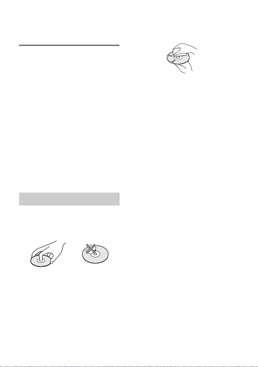
On cleaning
• Before playing, clean the disc with a cleaning
cloth.
Wipe the disc from the center out.
• Do not use solvents such as benzine, thinner,
commercially available cleaners, or anti-static
spray intended for vinyl LPs.
This system can only play back a standard
circular disc. Using neither standard nor circular
discs (e.g., card, heart, or star shape) may cause
a malfunction.
Do not use a disc that has a commercially
available accessory attached, such as a label or
ring.
Notes about Discs
On handling discs
• To keep the disc clean, handle the disc by its
edge. Do not touch the surface.
• Do not stick paper or tape on the disc.
• Do not expose the disc to direct sunlight or
heat sources such as hot air ducts, or leave it in
a car parked in direct sunlight as the
temperature may rise considerably inside the
car.
• After playing, store the disc in its case.
GB
9

Guide to the Control Menu Display
Use the Control Menu to select a function that you would like to use. The Control Menu display appears
when the DVD DISPLAY button is pressed. For details, refer to the page in parentheses.
Total number of
Currently playing title number (VIDEO
CD/Super Audio CD/CD: track number)
Currently playing chapter
number (VIDEO CD/Super
Audio CD/CD: index number)
Playing time
Icon of selected
Control Menu item
Control Menu items
titles or tracks
recorded
Disc name or
disc type
DVD
1 2 ( 2 7 ) TITLE 12
1 8 ( 3 4
T
1: ENGLISH
2: FRENCH
3: SPANISH
Currently playing
title name
)
1 : 3 2 : 5 5
Total number of chapters or indexes recorded
Playback status
(NPlayback, XPause, xStop, etc.)
DVD
Type of disc being
played back
Current setting
Options
Function name of sele cted
Control Menu item
Operation message
SUBTITLE
Select:
List of Control Menu Items
DISC Displays the disc name or the disc type inserted into the system.
TITLE (DVD only) (page 55)/
SCENE (only VIDEO CD in PBC playback) /
TRACK (VIDEO CD only) (page 55)
CHAPTER (DVD only) (page 56)/
INDEX (VIDEO CD only) (page 56)
ALBUM (MP3 only) (page 47, 55) Selects the album (MP3) to be played.
TRACK (Super Audio CD/CD/
MP3 only) (page 47, 55)
ORIGINAL/PLAY LIST (page 45) Selects the type of titles (DVD-RW) to be played, the
INDEX (Super Audio CD/CD only)
(page 56)
TIME (page 57) Checks the elapsed time and the remaining playback time.
AUDIO (DVD/VIDEO CD/Super
Audio CD/CD/MP3 only) (page 62)
ENTER
Selects the title (DVD) or the track (VIDEO CD) to be played.
Displays the scene (VIDEO CD in PBC playback).
Selects the chapter (DVD) or the index (VIDEO CD) to be
played.
Selects the track (Super Audio CD/CD/MP3) to be played.
[ORIGINAL] one, or an edited [PLAY LIST].
Displays the index and selects the index (Super Audio CD) to
be played.
Inputs the time code for picture and music searching.
Changes the audio setting.
10
SUBTITLE (DVD only) (page 71) Displays the subtitles.
Changes the subtitle language.
GB
ALBUM (JPEG only) (page 49) Selects the album (JPEG) to be played.
FILE (JPEG only) (page 49) Selects the file (JPEG) to be played.
DATE (JPEG only) (page 61) Displays the date information.
ANGLE (DVD VIDEO only)
(page 70)
PLAYMODE (VIDEO CD/Super
Audio CD/CD/MP3/JPEG only) (page 53)
REPEAT (page 53) Plays the entire disc (all titles/all tracks), one title/chapter/
CUSTOM PARENTAL
CONTROL (page 72)
Tips
• Each time you press DVD DISPLAY, the Control Menu display changes as follows:
Control Menu display
Changes the angle.
Selects the play mode.
track/album, or contents of program repeatedly.
Sets the disc to prohibit playing.
m
Control Menu display off
The Control Menu items vary, depending on the disc.
• The Control Menu icon indicator lights up in green t unless you set the [REPEAT] setting to
[OFF].
• The [ANGLE] indicator lights up in green when multiple angles are recorded on the disc.
11
GB

Getting Started
Unpacking
Check that you have the following items:
• Speakers (5)
• Subwoofer (1)
• Surround amplifier (1)
• Control unit (1)
• IR transmitter
• IR receiver
• IR receiver stand (1)
For the front speakers
• Speaker stands (2)
• Covers of speaker stands (2)
• Screws (large) (4)
For the surround amplifier
• Speaker cord cover (1)
• Speaker cord holder (1)
• Screw (small) (1)
• Remote sensor (1)
• Cleaning cloth for the front panel (80 mm × 80 mm) (3.9 inches × 3.9 inches) (1)
• AM loop antenna (aerial) (1)
• FM wire antenna (aerial) (1)
• Speaker cords (5m × 5)
• Foot pads
•Video cord (1)
• Remote Commander (remote) RM-SP320 (1)
• Size AAA batteries (2)
• Operating Instructions
• Speaker and TV connections (card) (1)
**
*
(1)
(20)
*
(1)
12
*
The cords of the IR transmitter and IR receiver are for this system only. You cannot use a commercially available
extension cord.
**
If you position the speakers on the floor, attach the foot pads to the bottom face of the speakers.
If you hang the front speakers, center speaker or surround speakers on the wall, attach the foot pads to the rear
of the speakers.
GB
Using the Remote
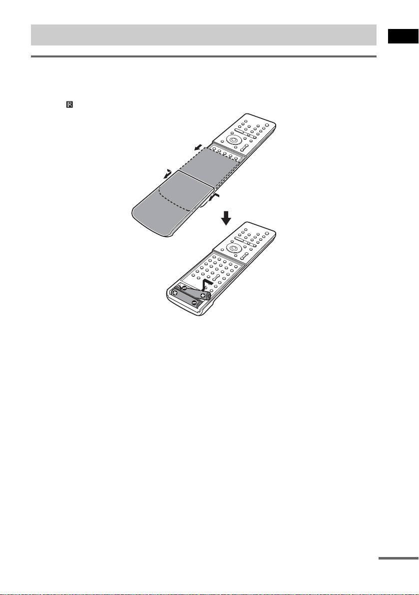
Inserting batteries into the remote
You can control the system using the supplied remote. Insert two size AAA (R03) batteries by matching
the 3 and # ends on the batteries to the markings inside the compartment. When using the remote,
point it at on the remote sensor.
1 Remove the cover.
2
2 Pinch the edges down.
Getting Started
Notes
• Do not leave the remote in an extremely hot or humid place.
• Do not use a new battery with an old one.
• Do not drop any foreign object into the remote casing, particularly when replacing the batteries.
• Do not expose the remote sensor to direct light from the sun or lighting apparatus. Doing so may cause a
malfunction.
• If you do not intend to use the remote for an extended period of time, remove the batteries to avoid possible damage
from battery leakage and corrosion.
continued
13
GB
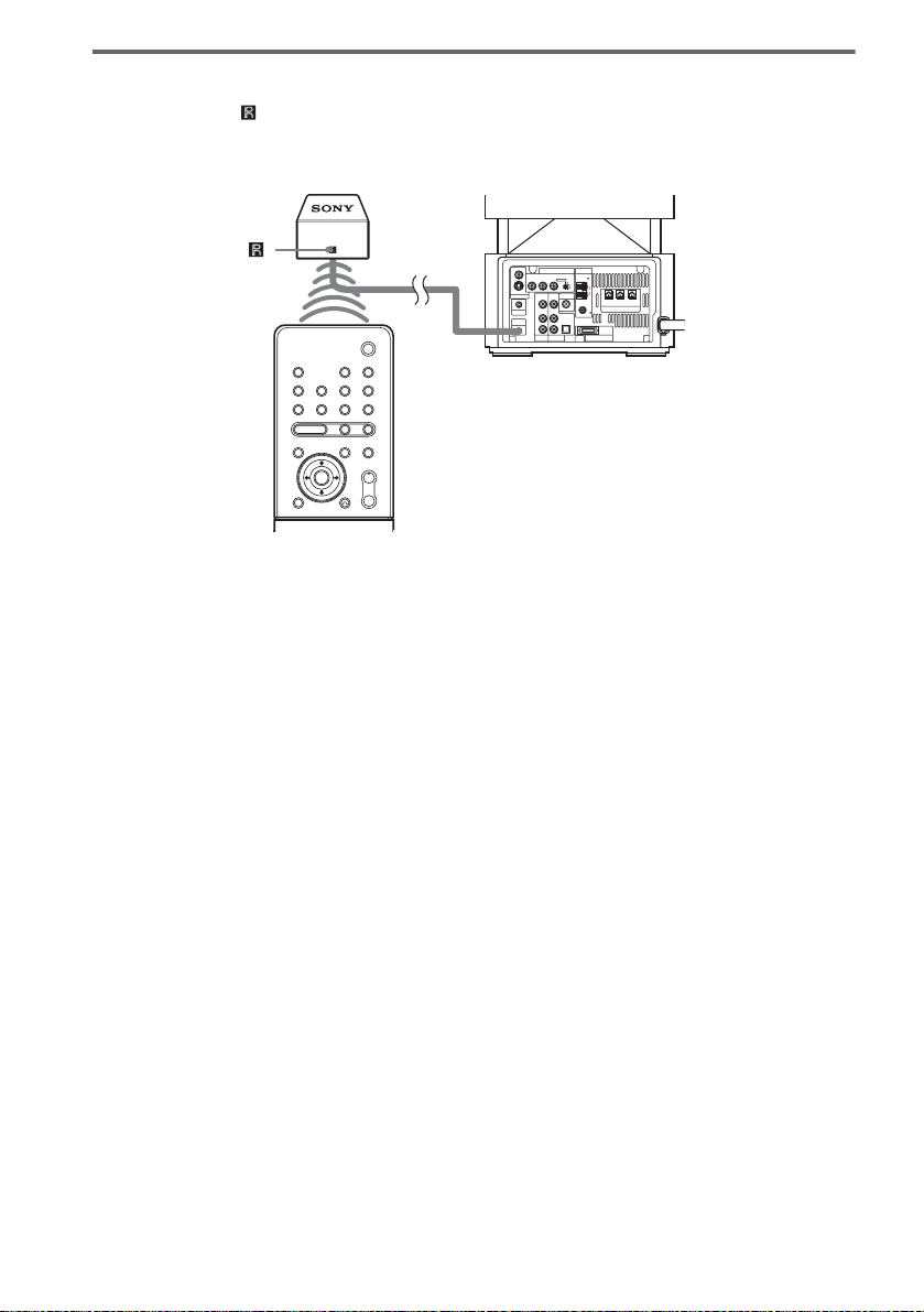
About the remote sensor
Point the remote at on the remote sensor. Connect the remote sensor to the DIR-R4 jack of the
subwoofer (page 110).
It is recommended to position the remote sensor near the Subwoofer.
Remote sensor
S VIDEO (DVD ONLY)
MONITOR OUTPUT
VIDEO
Y
PHONES
DIR-R4
Subwoofer
COMPONENT VIDEO OUT ANTENNA
PB/CBPR/CRSCAN SELECT
INTERLACESELECTABLE
VIDEO DIR-T1
VIDEO
IN
IN
AUDIO
AUDIO
IN
IN
COAXIAL
OPTICAL
DIGITAL IN
LL
R
R
SAT
VIDEO
AM
FM
75
SYSTEM CONNECTOR
FOR HCD-LF10
FRONT R
(FOR SS-TSL10 , SS-CTL10)
SPEAKER
CENTER FRONT L
14
GB
Step 1: Speaker System Hookup
Connect the supplied speaker system using the supplied speaker cords by matching the colors of the
jacks to those of the cords. For the surround speakers connect them to the surround amplifier that
receives the sound by wireless. Do not connect any speakers other than those supplied with this system.
To obtain the best possible surround sound, specify the speaker parameters (distance, level, etc.) on
page 36.
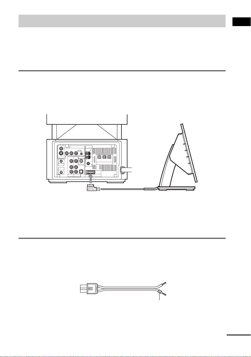
Connecting the subwoofer
Connect the system connector of the control unit to the SYSTEM CONNECTOR jack of the
subwoofer.
To insert the plug of the SYSTEM CONNECTOR cord, press and hold both sides of the plug.
Subwoofer
VIDEO
COMPONENT VIDEO OUT ANTENNA
PB/CBPR/CRSCAN SELECT
Y
INTERLACESELECTABLE
VIDEO DIR-T1
IN
AUDIO
IN
SAT
AM
CENTER FRONT L
FRONT R
(FOR SS-TSL10 , SS-CTL10)
SPEAKER
FM
75
COAXIAL
OPTICAL
DIGITAL IN
R
SYSTEM CONNECTOR
FOR HCD-LF10
S VIDEO (DVD ONLY)
MONITOR OUTPUT
PHONES
DIR-R4
VIDEO
IN
AUDIO
IN
LL
R
VIDEO
Getting Started
SYSTEM CONNECTOR cord
Control unit
Notes
• Do not handle the clear plastic panel when you move or operate the control unit as it may break.
• Before connecting/disconnecting the SYSTEM CONNECTOR cord, make sure the AC power cord (mains lead) is
disconnected from the wall outlet (mains).
Required cords
Speaker cords
The connector and the color tube of the speaker cords are the same color as the label of the jacks to be
connected.
(–)
(+)
color tube
(–)
(+)
continued
15
GB
Required equipments for the wireless system
IR transmitter
Transmits the sound by the infrared signals. Connect it to the DIR-T1 jack of the subwoofer.
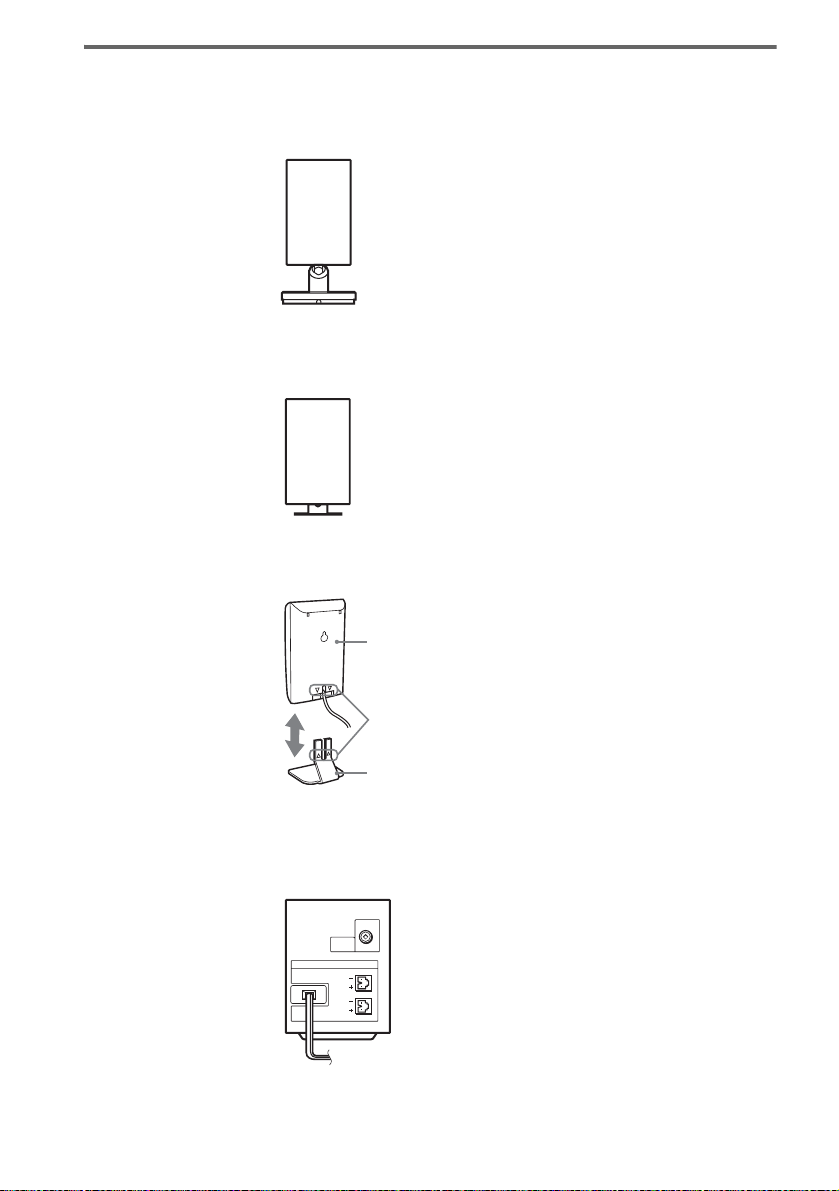
IR receiver
Receive the sound by the infrared ray. Connect it to the DIR-R1 jack of the surround amplifier.
When using the IR receiver stand, attach the stand so that both delta marks on the IR receiver and stand
are aligned.
IR receiver
16
Delta marks
IR receiver stand
Surround amplifier
Receive the sound from the IR receiver and send to the surround speakers.
Connect the surround speakers and the IR receiver to the surround amplifier.
DIR-R1
SPEAKER
SURROUND L
SURROUND R
GB
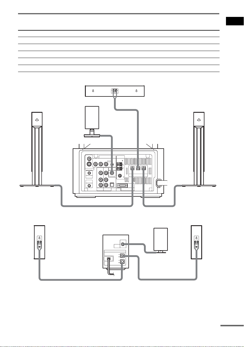
Terminals for connecting the speakers
Connect the To the
Front speakers SPEAKER FRONT L (white) and R (red) jacks of the system
Center speaker SPEAKER CENTER (green) jack of the system
Surround speakers SPEAKER SURR L (blue) and R (gray) jacks of the surround amplifier
IR transmitter DIR-T1 (pink) jack of the system
IR receiver DIR-R1 (light blue) jack of the surround amplifier
Center speaker
Getting Started
Front speaker (R)
Surround
speaker (R)
IR transmitter
Subwoofer
VIDEO
COMPONENT VIDEO OUT ANTENNA
PB/CBPR/CRSCAN SELECT
Y
S VIDEO (DVD ONLY)
VIDEO
MONITOR OUTPUT
IN
AUDIO
IN
PHONES
LL
DIR-R4
R
VIDEO
Surround amplifier
VIDEO DIR-T1
IN
AUDIO
IN
R
SAT
SURROUND L
SURROUND R
OPTICAL
DIGITAL IN
SPEAKER
INTERLACESELECTABLE
DIR-R1
AM
FM
75
COAXIAL
SYSTEM CONNECTOR
FOR HCD-LF10
FRONT R
CENTER FRONT L
(FOR SS-TSL10 , SS-CTL10)
SPEAKER
Front speaker (L)
IR receiver
Surround
speaker (L)
continued
17
GB
Tip
You can install the front speakers and surround speakers to optional speaker stands (not supplied).
Notes on placing speakers
• Do not set the speakers in an inclined position.
• Do not place the speakers in locations that are:
– Extremely hot or cold
– Dusty or dirty
– Very humid
– Subject to vibrations
– Subject to direct sunlight
• Use caution when placing the subwoofer or tall speakers on a specially treated (waxed, oiled, polished, etc.) floor,
as staining or discoloration may result.
Notes on placing IR transmitter and IR receiver
• Do not install the IR receiver in a place exposed to direct sunlight or strong light such as an incandescent lamp.
• The cords of the IR transmitter and IR receiver are for this system only. You cannot use a commercially available
extension cord.
Note
Do not catch the speaker cable insulation in the SPEAKER jack.
Tip
Connect the speaker cable after bending the speaker wire at the end of the insulation. This prevents the speaker cable
from being caught in the SPEAKER jack.
18
GB
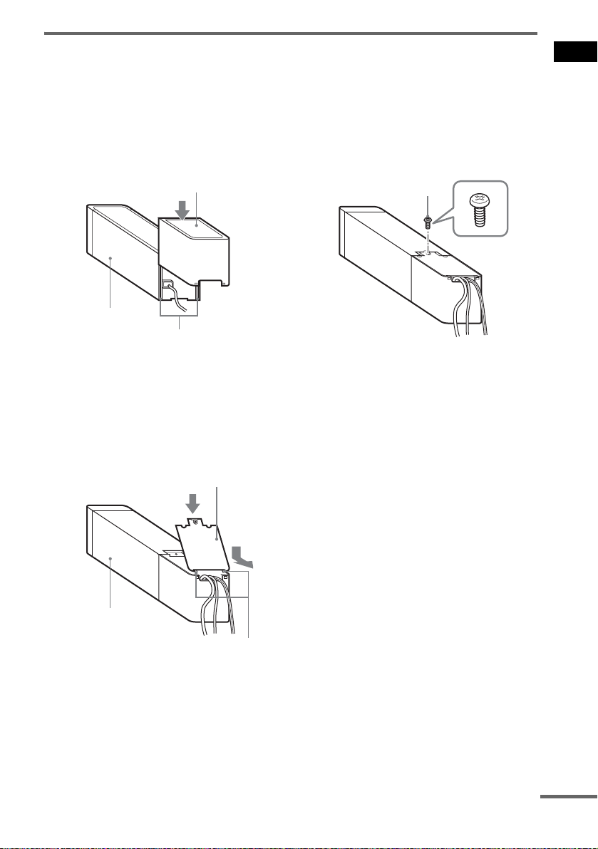
About the surround amplifier
After connecting, you can attach the cover to the surround amplifier for organizing and storing excess
speaker cords.
Attaching the cover
1 Attach the speaker cord cover by
sliding it down along the grooves at the
edges of the surround amplifier.
Speaker cord cover
Surround amplifier
Grooves
Push the speaker cord cover down until you
hear a click. Turn the surround amplifier
upside down, then store the cords in the
speaker cord cover.
2 Insert the tabs of the speaker cord
holder in the slots of the speaker cord
cover, and press it into place.
Speaker cord holder
3 Secure the speaker cord holder with
the supplied screw (small).
Screw
Notes
• Do not use the speaker cord cover and holder without
the supplied screw.
• Before detaching the speaker cord cover, first remove
the screw, then the speaker cord holder. Forcing the
speaker cord cover off with the screw in place may
cause damage.
• Gently pull apart the side of the speaker cord cover
when detaching.
Getting Started
Surround amplifier
Tabs
continued
19
GB

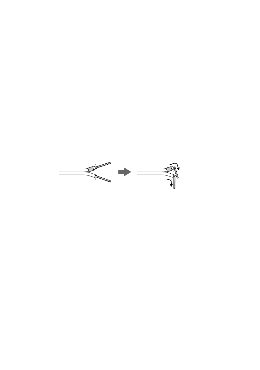
To avoid short-circuiting the speakers
Short-circuiting of the speakers may damage the system. To prevent this, be sure to follow these
precautions when connecting the speakers. Make sure the bare wire of each speaker cord does not touch
another speaker jack or the bare wire of another speaker cord.
Examples of poor conditions of the speaker cord
Stripped speaker cord is
touching another speaker
terminal.
After connecting all the components, speakers, and AC power cord (mains lead), output a test tone to
check that all the speakers are connected correctly. For details on outputting a test tone, see page 93.
If no sound is heard from a speaker while outputting a test tone, or a test tone is output from a speaker
other than the one currently displayed in the front panel display, the speaker may be short-circuited. If
this happens, check the speaker connection again.
Notes
• Be sure to match the speaker cord to the appropriate terminal on the components: 3 to 3, and # to #. If the cords
are reversed, the sound will lack bass and may be distorted.
• If you connect the speaker cord incorrectly or turn up the volume in a state of a short circuit, the standby indicator
flashes and the system enters standby mode. In this case, disconnect and then reconnect the AC power cord (mains
lead) from the wall outlet (mains), and then turn the system on.
• If you connect the speaker cord to the surround amplifier incorrectly, or turn up the volume in a state of a short
circuit, the POWER/ON LINE indicator turns off. In this case, disconnect the AC power cord (mains lead) of the
surround amplifier from the wall outlet (mains), reconnect, and then turn the surround amplifier on.
Stripped cords are touching
each other due to excessive
removal of insulation.
20
GB
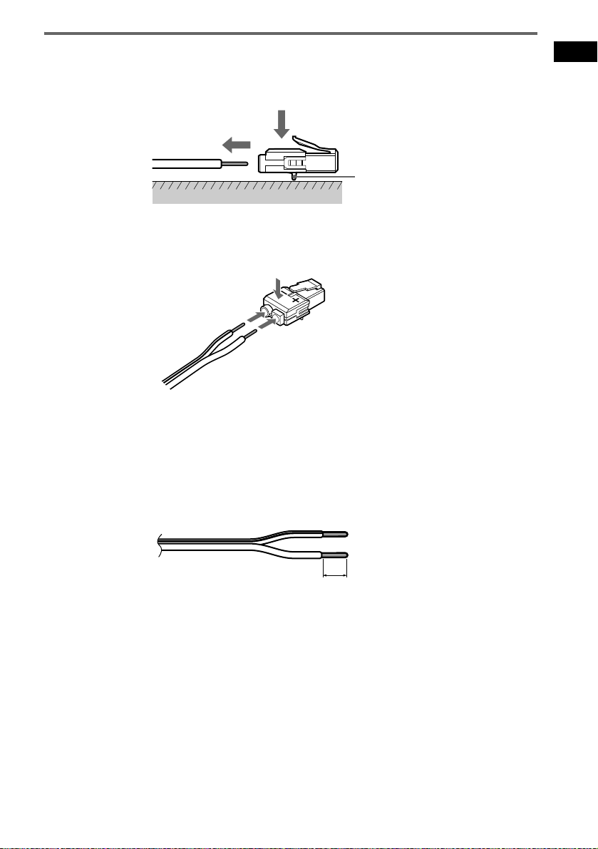
To change the speaker cables
If you want to use a different speaker cable, you can detach the plug for attachment to another cable.
Detaching
Catcher
With the catcher facing down, press and hold the plug down against a flat surface and remove the cords
from plug.
Attaching
While pressing the plug down against a flat surface, insert the new speaker cords.
Note that the cord marked with a line should be attached to the minus (-) side of the plug.
Note
Be careful not to damage the surface you use (desk, etc.) when attaching/detaching the speaker cords.
Tips
• You can use any commercially sold speaker cable of gauge cord AWG #18 - AWG #22.
• Before attaching a new cable, strip off 10 mm (
13
/32 inch) of its insulation and twist the bare wires of both cords.
Getting Started
10 mm
13
/32 inch
21
GB
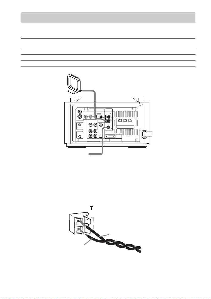
Step 2: Antenna (Aerial) Hookups
Connect the supplied AM/FM antennas (aerials) for listening to the radio.
Terminals for connecting the antennas (aerials)
Connect the To the
AM loop antenna (aerial) AM terminals
FM wire antenna (aerial) FM 75Ω COAXIAL jack
AM loop antenna (aerial)
VIDEO
COMPONENT VIDEO OUT ANTENNA
PB/CBPR/CRSCAN SELECT
Y
S VIDEO (DVD ONLY)
MONITOR OUTPUT
PHONES
DIR-R4
FM wire antenna (aerial)
INTERLACESELECTABLE
VIDEO
VIDEO DIR-T1
IN
IN
AUDIO
AUDIO
IN
IN
OPTICAL
DIGITAL IN
LL
R
R
VIDEO
SAT
AM
FM
75
COAXIAL
SYSTEM CONNECTOR
FOR HCD-LF10
FRONT R
CENTER FRONT L
(FOR SS-TSL10 , SS-CTL10)
SPEAKER
22
Notes
• To prevent noise pickup, keep the AM loop antenna (aerial) away from the system and other components.
• Be sure to fully extend the FM wire antenna (aerial).
• After connecting the FM wire antenna (aerial), keep it as horizontal as possible.
Tip
When you connect the supplied AM loop antenna (aerial), the cord (A) and the cord (B) can be connected in either
terminal.
AM
A
B
GB
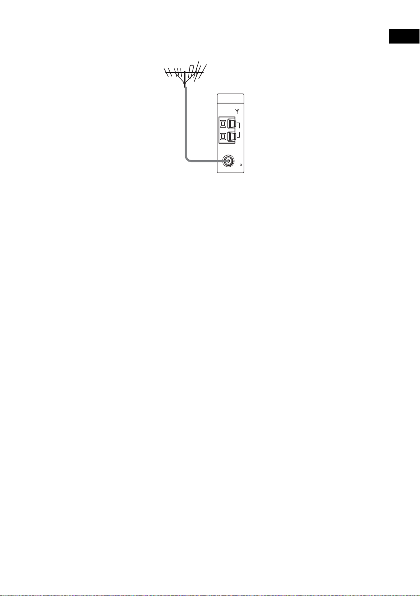
Tip
If you have poor FM reception, use a 75-ohms coaxial cable (not supplied) to connect the system to an outdoor
FM antenna (aerial) as shown below.
Outdoor FM
antenna (aerial)
ANTENNA
System
AM
FM
75
COAXIAL
Getting Started
23
GB
Step 3: TV and Video Component Hookups
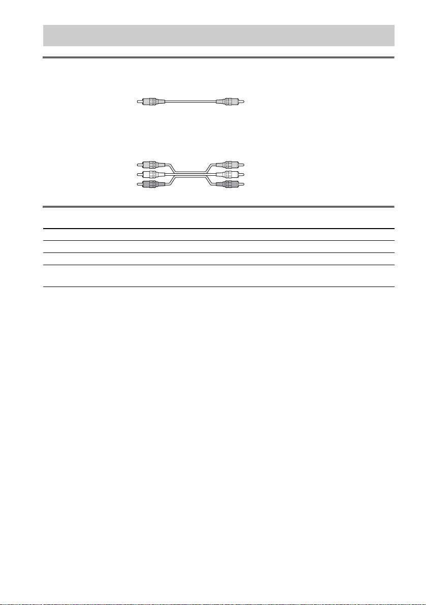
Required cords
Video cord for connecting a TV
Yellow
Audio/video cords (not supplied)
When connecting a cord, be sure to match the color-coded sleeves to the appropriate jacks on the
components.
Yellow (Video)
White (L/audio)
Red (R/audio)
Terminals for connecting video components
Connect the To the
TV (VIDEO IN) MONITOR OUTPUT (VIDEO) jack
VCR (VIDEO/AUDIO OUT) VIDEO (VIDEO IN/AUDIO IN (L/R)) jacks
Digital satellite receiver
(VIDEO/AUDIO OUT)
Notes
• The video signal is output as below:
– When [COMPONENT OUT] is set to [INTERLACE] in [SCREEN SETUP] (page 89) (default)
The video signal is output from the S VIDEO and VIDEO jacks of MONITOR OUTPUT.
– When [COMPONENT OUT] is set to [PROGRESSIVE] in [SCREEN SETUP] (page 89)
The video signal is output from the COMPONENT VIDEO OUT jacks only.
• When you connect a VCR or digital satellite receiver to the VIDEO/SAT jacks of the subwoofer, change the
function to VIDEO or SAT (page 81).
• The S VIDEO jack and COMPONENT VIDEO OUT jacks output video signals only when DVD is selected (by
pressing FUNCTION repeatedly until “DVD” appears in the front panel display).
Tips
• When using the S video jack instead of the video jacks, your TV monitor must also be connected via an S video
jack. S video signals are on a separate bus from the video signals and will not be output through the video jacks.
• When using the COMPONENT VIDEO OUT jacks (Y, P
must also be connected via COMPONENT VIDEO OUT jacks (Y, P
format signals, you must use this connection and set [COMPONENT OUT] to [PROGRESSIVE] in [SCREEN
SETUP] (page 89).
SAT (VIDEO IN/AUDIO IN (L/R)) jacks
or OPTICAL DIGITAL IN jack
B/CB, PR/CR) instead of the video jacks, your TV monitor
B/CB, PR/CR). If your TV accepts progressive
24
GB

TV with S VIDEO IN jack
TV
Getting Started
S VIDEO
IN
IN
VIDEO
S VIDEO (DVD ONLY)
MONITOR OUTPUT
PHONES
DIR-R4
COMPONENT VIDEO OUT ANTENNA
PB/CBPR/CRSCAN SELECT
Y
VIDEO
VIDEO DIR-T1
IN
IN
AUDIO
AUDIO
IN
IN
LL
R
VIDEO
OUT
VIDEO
OUT
AUDIO
OUT
L
R
INPUTINPUT
VIDEO
IN
IN
INTERLACESELECTABLE
AM
CENTER FRONT L
FRONT R
(FOR SS-TSL10 , SS-CTL10)
FOR HCD-LF10
OUTOUT
OPTICAL
DIGITAL
OUT
L
R
SPEAKER
COMPONENT
VIDEO IN
Y
PB/CB
PR/CR
IN
FM
75
COAXIAL
OPTICAL
DIGITAL IN
R
SAT
SYSTEM CONNECTOR
VIDEO
OUT
AUDIO
OUT
TV, VCR, etc. Digital satellite receiver or
PlayStation 2 etc.
TV with COMPONENT
VIDEO IN jack
Notes
• Make connections securely to prevent unwanted noise.
• Refer to the instructions supplied with the TV.
• The system cannot output an audio signal to the connected TV. Only the audio signal of the TV is output from the
system speakers.
If you connect a digital satellite receiver with an OPTICAL OUT jack
The digital satellite receiver can be connected to the SAT OPTICAL DIGITAL IN jack instead of the
SAT AUDIO IN (L/R) jacks of the system.
continued
25
GB

The system can accept both the digital and analogue signals. Digital signals have priority over analogue
signals. If the digital signal ceases, the analogue signal will be processed after 2 seconds.
If you connect a digital satellite receiver without an OPTICAL OUT jack
Connect the digital satellite receiver to the SAT AUDIO IN (L/R) jacks only of the system.
To listen to TV, VCR or game machine (e.g., PlayStation 2) sound with
the system
Connect the audio output jacks of the TV, VCR or game machine to the VIDEO AUDIO IN (L/R) or
SAT AUDIO IN (L/R) jacks of the system with audio cords (not supplied).
To change the color system (PAL or NTSC)*
* Asian, Australian, and Saudi Arabian models only.
Depending on the TV to be connected, you may be required to select either PAL or NTSC of the
system.
The initial setting of the system for Australian and Saudi Arabian models is PAL.
The initial setting of the system for Asian models is NTSC.
If the color system of the TV is PAL
To set the system to PAL from NTSC:
1 Press AMP MENU.
2 Press X/x repeatedly until “Customize” appears in the front panel display, then press ENTER or
c.
The system enters the Customize Menu mode.
3 Press X/x repeatedly until “Color System Change” appears in the front panel display, then press
ENTER or c.
“Color System Change No” is displayed.
4 Press X/x to select “Color System Change Yes”.
5 Press ENTER.
Note
When the function is DVD, it takes a while until the images on the TV appears.
If the color system of the TV is NTSC
Do the same operation above to set the system to NTSC from PAL.
26
When connecting to a standard 4:3 screen TV
Depending on the disc, the image may not fit your TV screen.
If you want to change the aspect ratio, please refer to page 88.
Does your TV accept progressive signals?
Progressive is the method for displaying TV images which reduces flickering, and sharpens the image.
To display using this method, you need to connect to a TV that accepts progressive signals and set the
output signal of COMPONENT VIDEO OUT to the progressive format. For details, see “To set to
[PROGRESSIVE]” on page 89.
GB

If your TV does not accept progressive signals and progressive format
is set by mistake
The image may not appear, or will appear distorted. In this case, set the COMPONENT VIDEO OUT/
SCAN SELECT switch on the rear panel of the subwoofer to INTERLACE.
Getting Started
continued
27
GB
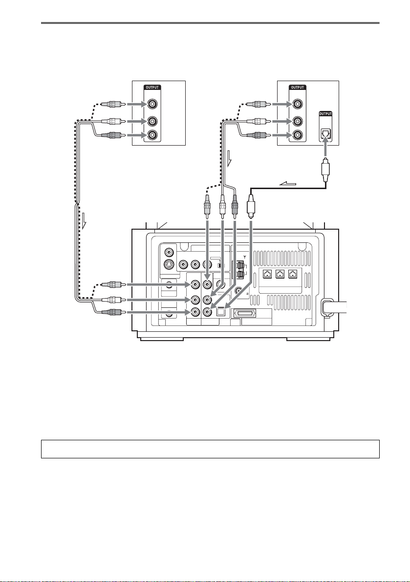
Connect to a TV with audio output jacks
TV, VCR, etc.
VIDEO
1
OUT
AUDIO
OUT
L
R
VIDEO
S VIDEO (DVD ONLY)
MONITOR OUTPUT
PHONES
DIR-R4
or
COMPONENT VIDEO OUT ANTENNA
PB/CBPR/CRSCAN SELECT
Y
LL
R
VIDEO
INTERLACESELECTABLE
VIDEO DIR-T1
VIDEO
IN
IN
AUDIO
AUDIO
IN
IN
OPTICAL
DIGITAL IN
R
SAT
AM
FM
75
COAXIAL
SYSTEM CONNECTOR
FOR HCD-LF10
Digital satellite receiver,
PlayStation 2, etc.
VIDEO
1
OUT
AUDIO
OUT
L
R
FRONT R CENTER FRONT L
(FOR SS-TSL10 , SS-CTL10)
SPEAKER
2
OPTICAL
DIGITAL
OUT
28
Connect the AUDIO OUT (L/R) jacks (1) to the VIDEO or SAT AUDIO IN (L/R) jacks of this
subwoofer with audio cords (not supplied). If your TV does not have the AUDIO OUT (L/R) jacks,
you cannot output the TV sound from the speakers of this subwoofer. If your TV has an OPTICAL
DIGITAL OUT jack (2), connect to the SAT OPTICAL DIGITAL IN jack of this subwoofer using
an optical digital cord (not supplied).
Tip
Select either VIDEO or SAT, according to the TV connection, by pressing FUNCTION repeatedly (page 69).
To enjoy TV sound from all speakers
When you want to output the TV sound or stereo sound of a 2 channel source from the 6 speakers, select any sound
field other than “Auto Format Direct Auto” or “2Channel Stereo” (page 64).
GB
Step 4: Connecting the AC Power Cords (Mains Leads) and Powering On
Before connecting the AC power cords (mains leads) of the subwoofer and the surround amplifier to a
wall outlet (mains), connect the front and center speakers to the subwoofer and surround speakers to
the surround amplifier (see page 17).
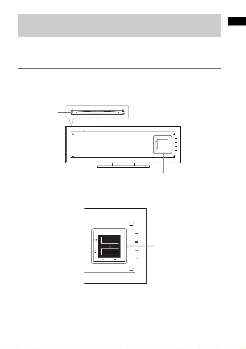
Powering the control unit on
After powering the control unit on, initialization begins. During initialization, do not touch the front
panel display.
Press "/1 on the control unit or the remote, or insert a disc to turn the system on.
"/1
FUNCTION
+
VOL.
-
Front panel display
Note
During initialization, an animation appears on the front panel display for about 5 seconds. Each time the system turns
on, initialization begins.
Getting Started
FUNCTION
+
VOL.
-
Front panel display
29
GB
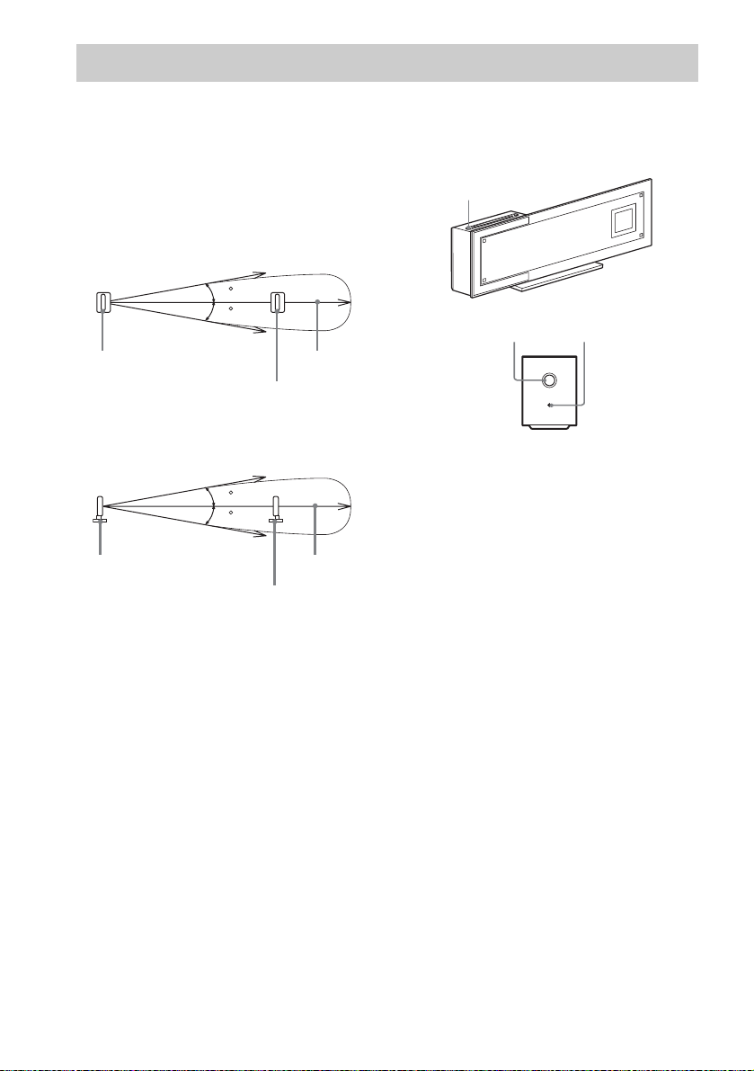
Step 5: Adjusting the Wireless System
About the wireless system
This wireless system adopts the Digital Infrared
Audio Transmission system (page 103). The
following diagram indicates the infrared
transmission area (the range that the infrared
rays can reach).
Top view
IR transmitter
Side view
IR transmitter
Notes
• Do not install the IR receiver in a place exposed to
direct sunlight or strong light such as an incandescent
lamp.
• Do not use the IR receiver that is not supplied with the
system.
10
10
10
10
IR receiver
Infrared signal
IR receiver
Infrared signal
Approx. 10m
(33 ft)
Approx. 10m
(33 ft)
After connecting the speakers, surround
amplifier, IR transmitter, IR receiver, and the
AC power cords (mains leads), adjust the
wireless system for good transmission.
"/1
POWER/ON LINE
POWER
indicator
POWER
POWER ON-LINE
1 Press "/1 on the system and POWER
on the surround amplifier.
The system and surround amplifier turn on
and the POWER/ON LINE indicator turns
red.
2 Orient the IR transmitter and IR
receiver to face each other.
Adjust the position until the POWER/ON
LINE indicator on the surround amplifier
turns green.
Tips
• The IR transmitter is movable for easy reorientation.
• You can change the setting of the surround speakers
so that the designated sounds for the left and right
speakers are reversed (page 96).
Notes
• Make sure that there is no obstruction such as a
person or object be tween the IR transmitter and t he IR
receiver. Otherwise, the sound from the surround
speakers may be interrupted.
• If the POWER/ON LINE indicator on the surround
amplifier turns red, the transmission is incomplete.
Adjust the position of the IR transmitter and IR
receiver until the POWER/ON LINE indicator turns
green.
• If the POWER/ON LINE indicator on the surround
amplifier flashes in red, the IR receiver is receiving
an infrared signal from another Sony's wireless
product. Move the IR transmitter and/or the IR
receiver so that the POWER/ON LINE indicator
turns green.
30
GB
 Loading...