

Page 1
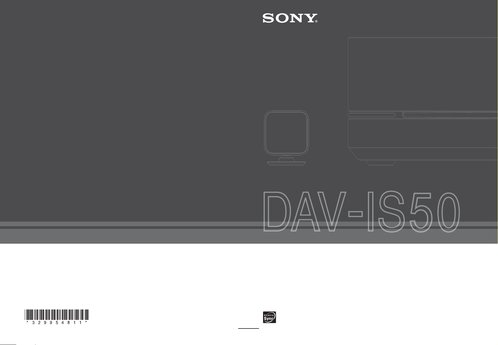
3-299-548-11(1)
(1)
Sony Corporation Printed in Malaysia
DVD Home Theatre System
Operating Instructions
©2008 Sony Corporation
http://www.sony.net/
Page 2
3
WARNING
To reduce the risk of fire or electric
shock, do not expose this apparatus to
rain or moisture.
Caution – The use of optical instruments
with this product will increase eye
hazard.
Do not install the appliance in a confined space, such
as a bookcase or built-in cabinet.
To prevent fire or shock hazard, do not place objects
filled with liquids, such as vases, on the apparatus.
Batteries or batteries installed apparatus shall not be
exposed to excessive heat such as sunshine, fire or the
like.
To prevent fire, do not cover the ventilation of the
apparatus with news papers, table-cloths, curtains, etc.
And don’t place lighted candles on the apparatus.
For the customers in the U.S.A
This symbol is intended to alert the user to
the presence of uninsulated “dangerous
voltage” within the product’s enclosure that
may be of sufficient magnitude to constitute
a risk of electric shock to persons.
This symbol is intended to alert the user to
the presence of important operating and
maintenance (servicing) instructions in the
literature accompanying the appliance.
Owner’s Record
The model and serial numbers are l ocated at the bottom
exterior of the control unit. Record the serial number in
the space provided below. Refer to them whenever you
call upon your Sony dealer regarding this product.
Model No. DAV-IS50
Serial No.______________
WARNING
The following FCC statement applies only to the
version of this model manufactured for sale in the
USA. Other versions may not comply with FCC
technical regulations.
This equipment has been tested and found to comply
with the limits for a Class B digital device, pursuant to
Part 15 of the FCC Rules. These limits are designed to
provide reasonable protection against harmful
interference in a residential installation. This
equipment generates, uses, and can radiate radio
frequency energy and, if not installed and used in
accordance with the instructions, may cause harmful
interference to radio communications. However, there
is no guarantee that interference will not occur in a
particular installation. If this equipment does cause
harmful interference to radio or television reception,
which can be determined by turning the equipment off
and on, the user is encouraged to try to correct the
interference by one or more of the following measures:
– Reorient or relocate the receiving antenna (aerial).
– Increase the separation between the equipment and
receiver.
– Connect the equipment into an outlet on a circuit
different from that to which the receiver is
connected.
– Consult the dealer or an experienced radio/TV
technician for help.
CAUTION
You are cautioned that any changes or modifications
not expressly approved in this manual could void your
authority to operate this equipment.
Important Safety Instructions
1) Read these instructions.
2) Keep these instructions.
3) Heed all warnings.
4) Follow all instructions.
5) Do not use this apparatus near water.
6) Clean only with dry cloth.
7) Do not block any ventilation openings. Install in
accordance with the manufacturer’s instructions.
8) Do not install near any heat sources such as
radiators, heat registers, stoves, or other apparatus
(including amplifiers) that produce heat.
9) Do not defeat the safety purpose of the polarized or
grounding-type plug. A polarized plug has two
blades with one wider than the other. A grounding
type plug has two blades and a third grounding
prong. The wide blade or the third prong are
provided for your safety. If the provided plug does
not fit into your outlet, consult an electrician for
replacement of the obsolete outlet.
US
2
Page 3

10) Protect the power cord from being walked on or
pinched particularly at plugs, convenience
receptacles, and the point where they exit from the
apparatus.
11) Only use attachments/accessories specified by the
manufacturer.
12) Use only with the cart, stand, tripod, bracket, or
table specified by the manufacturer, or sold with
the apparatus. When a cart is used, use caution
when moving the cart/apparatus combination to
avoid injury from tip-over.
13) Unplug this apparatus during lightning storms or
when unused for long periods of time.
14) Refer all servicing to qualified service personnel.
Servicing is required when the apparatus has been
damaged in any way, such as power-supply cord or
plug is damaged, liquid has been spilled or objects
have fallen into the apparatus, the apparatus has
been exposed to rain or moisture, does not operate
normally, or has been dropped.
Note to CATV system installer:
This reminder is provided to call the CATV system
installer’s attention to Article 820-40 of the NEC that
provides guidelines for proper grounding and, in
particular, specifies that the cable ground shall be
connected to the grounding system of the building, as
close to the point of cable entry as practical.
Precautions
On power sources
• The unit is not disconnected from the AC power
source (mains) as long as it is connected to the wall
outlet (mains), even if the unit itself has been turned
off.
• Install this system so that the AC power cord (mains
lead) can be unplugged from the wall socket
immediately in the event of trouble.
About This Operating Instructions
• The instructions in this Operating Instructions
describe the controls on the remote. You can
also use the controls on the control unit if they
have the same or similar names as those on the
remote.
• The Control Menu items may be different
depending on the area.
• “DVD” may be used as a general term for a
DVD VIDEO, DVD+RW/DVD+R, and
DVD-RW/DVD-R.
• Measurements are expressed in feet (ft) for
North American models.
• The default setting is underlined.
About the S-AIR function
The system is compatible with the S-AIR
function, which allows transmission of sound
between S-AIR products wirelessly.
The following S-AIR products can be used with
the system:
• Surround amplifier: You can enjoy surround
speaker sound wirelessly.
• S-AIR receiver: You can enjoy system sound
in another room.
These S-AIR products can be purchased as an
option (the S-AIR product lineup differs
depending on the area).
Notes or instructions for the surround amplifier
or S-AIR receiver in this operating instructions
refer only to when the surround amplifier or
S-AIR receiver is used.
For details on the S-AIR function, see “Using an
S-AIR Product” (page 63).
US
3
Page 4

Table of Contents
About This Operating Instructions.......... 3
About the S-AIR function ....................... 3
Playable Discs ......................................... 6
Getting Started
Step 1: Positioning the Speakers........... 11
Step 2: Connecting the System .............17
Step 3: Performing the Quick Setup .....25
Basic Operations
Playing a Disc ....................................... 29
Enjoying the Radio or Other
Components .................................... 32
Enjoying Sound from all Speakers .......34
Various Functions for Playing
Discs
Searching for a Title/Chapter/Track/
Scene, etc. ....................................... 35
Resuming Playback from the Point
Where You Stopped the Disc .........36
(Resume Play)
Creating Your Own Program ................ 37
(Program Play)
Playing in Random Order .....................38
(Shuffle Play)
Playing Repeatedly ............................... 39
(Repeat Play)
Using the DVD’s Menu ........................ 40
Changing the Sound.............................. 41
Selecting [ORIGINAL] or
[PLAY LIST] on a DVD-VR .........42
Viewing Information About the Disc ...43
Changing the Angles............................. 45
Displaying the Subtitles ........................ 46
Adjusting the Delay Between the
Picture and Sound........................... 46
(A/V SYNC)
Playing MP3 Files/JPEG Image Files .. 47
Playing MP3 Files and JPEG Image
Files as a Slide Show with Sound .. 50
Playing a VIDEO CD with PBC
Functions (Ver.2.0) ........................ 51
(PBC Playback)
Sound Adjustments
Enjoying Surround Sound by Using
Decoding Mode .............................. 52
Selecting the Sound Mode.................... 54
Adjusting the Bass, Middle, and
Treble Level ................................... 55
Tuner Functions
Presetting Radio Stations...................... 56
Listening to the Radio .......................... 57
Control for HDMI/External
Audio Device
Using the Control for HDMI Function
for “BRAVIA” Sync ...................... 59
Using the DIGITAL MEDIA PORT
Adapter ........................................... 62
Using an S-AIR Product ....................... 63
US
4
Page 5

Other Operations
Controlling the TV with the Supplied
Remote............................................ 69
Enjoying Multiplex Broadcast Sound... 71
(DUAL MONO)
Enjoying the Sound at Low Volume..... 71
(NIGHT MODE)
Using the Sleep Timer ..........................72
Changing the Brightness of the Front
Panel Display .................................. 72
Changing the Display Mode ................. 73
(INFORMATION MODE)
Changing the Display Appearance
of the Soft-touch Buttons................ 73
(ILLUMINATION MODE)
Advanced Settings and
Adjustments
Restricting Playback of the Disc ........... 75
(PARENTAL CONTROL)
Calibrating the Appropriate Settings
Automatically ................................. 77
(AUTO CALIBRATION)
Using the Setup Display........................ 79
Setting the Display or Sound Track
Language ........................................ 80
[LANGUAGE SETUP]
Settings for the Display......................... 80
[VIDEO SETUP]
Settings for the HDMI .......................... 82
[HDMI SETUP]
Settings for the Audio ........................... 83
[AUDIO SETUP]
Other Settings........................................84
[SYSTEM SETUP]
Settings for the Speakers....................... 85
[SPEAKER SETUP]
Returning to the Default Settings..........88
Additional Information
Precautions............................................ 89
Notes about the Discs ........................... 90
Troubleshooting.................................... 91
Self-diagnosis Function ........................ 98
(When letters/numbers appear in
the display)
Specifications........................................ 99
Glossary .............................................. 100
Language Code List............................ 102
Index to Parts and Controls ................ 103
Guide to the Control Menu Display ... 108
Index ................................................... 111
US
5
Page 6
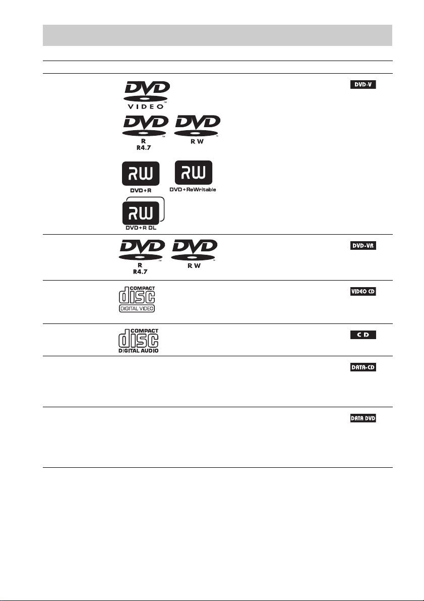
Playable Discs
Type Disc logo Characteristics Icon
DVD VIDEO • DVD VIDEO
• DVD-R/DVD-RW in DVD
VIDEO format or video mode
• DVD+R/DVD+RW in DVD
VIDEO format
VR (Video
Recording) mode
• DVD-R/DVD-RW in VR (Video
Recording) mode (except for
DVD-R DL)
VIDEO CD • VIDEO CD (Ver. 1.1 and 2.0 discs)
•Super VCD
• CD-R/CD-RW/CD-ROM in video
CD format or Super VCD format
CD • Audio CD
• CD-R/CD-RW in audio CD format
DATA CD – • CD-R/CD-RW/CD-ROM in
DATA CD format, containing MP3
files1), JPEG image files2), and
conforming to ISO 96603) Level 1/
Level 2, or Joliet (extended format)
DATA DVD – • DVD-ROM/DVD-R/DVD-RW/
DVD+R/DVD+RW in DATA
DVD format, containing MP3
files1), JPEG image files2), and
conforming to UDF (Universal
Disk Format)
1)
MP3 (MPEG 1 Audio Layer 3) is a standard format defined by ISO/MPEG which compresses audio data. MP3 files
must be in MPEG 1 Audio Layer 3 format.
2)
JPEG image files must conform to the DCF image file format. (DCF “Design rule for Camera File system”: Image
standards for digital cameras regulated by Japan Electronics and Information Technology Industries Association
(JEITA)).
3)
A logical format of files and folders on CD-ROMs, defined by ISO (International Organization for
Standardization).
“DVD-RW,” “DVD+RW,” “DVD+R,” “DVD VIDEO,” and the “CD” logos are trademarks.
US
6
Page 7
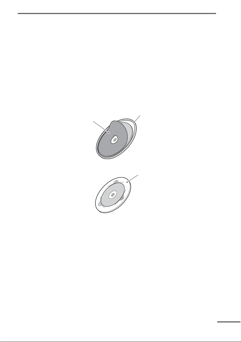
Example of discs that the system cannot play
d
The system cannot play the following discs:
• CD-ROM/CD-R/CD-RW other than those recorded in the formats listed on page 6
• CD-ROM recorded in PHOTO CD format
• Data part of CD-Extra
• CD Graphics disc
• DVD Audio
• Data DVD that does not contain MP3 files or JPEG image files
•DVD RAM
• Super Audio CD
Also, the system cannot play the following discs:
• A DVD VIDEO with a different region code (page 8).
• A disc that has a non-standard shape (e.g., card shaped, heart shaped).
• A disc that has a commercially available accessory attached, such as a label or ring.
Ring
Label
• An adapter to convert an 8 cm disc to standard size.
Adapter
• A disc with paper or stickers on it.
• A disc that has the adhesive of cellophane tape or a sticker still left on it.
Notes about CD-R/CD-RW/DVD-R/DVD-RW/DVD+R/DVD+RW
In some cases, CD-R/CD-RW/DVD-R/DVD-RW/DVD+R/DVD+RW cannot be played on this system
due to the recording quality or physical condition of the disc, or the characteristics of the recording
device and authoring software.
The disc will not play if it has not been correctly finalized. For more information, refer to the operating
instructions for the recording device.
Note that some playback functions may not work with some DVD+RWs/DVD+Rs, even if they have
been correctly finalized. In this case, view the disc by normal playback. Also some DATA-CDs/
DATA-DVDs created in Packet Write format cannot be played.
continue
US
7
Page 8

Music discs encoded with copyright protection technologies
This product is designed to play back discs that conform to the Compact Disc (CD) standard.
Recently, various music discs encoded with copyright protection technologies are marketed by some
record companies. Please be aware that among those discs, there are some that do not conform to the
CD standard and may not be playable by this product.
Note on DualDiscs
A DualDisc is a two sided disc product which mates DVD recorded material on one side with digital
audio material on the other side.
However, since the audio material side does not conform to the Compact Disc (CD) standard, playback
on this product is not guaranteed.
About Multi Session CD
• This system can play a Multi Session CD when an MP3 file is contained in the first session. Any
subsequent MP3 files recorded in later sessions can also be played back.
• This system can play a Multi Session CD when a JPEG image file is contained in the first session.
Any subsequent JPEG image files recorded in later sessions can also be played back.
• If MP3 files and JPEG image files in music CD format or video CD format are recorded in the first
session, only the first session will be played back.
Region code
Your system has a region code printed on the bottom of the control unit and will only play a DVD
labeled with the same region code.
A DVD VIDEO labeled will also play on this system.
If you try to play any other DVD VIDEO, the message [Playback prohibited by area limitations.] will
appear on the TV screen. Depending on the DVD VIDEO, no region code indication may be given even
though playing the DVD VIDEO is prohibited by area restrictions.
ALL
Note about playback operations of a DVD and VIDEO CD
Some playback operations of a DVD and VIDEO CD may be intentionally set by software producers.
Since this system will play a DVD or VIDEO CD according to the disc contents the software producers
designed, some playback features may not be available. Be sure to read the operating instructions
supplied with the DVD or VIDEO CD.
US
8
Page 9

Copyrights
This product incorporates copyright protection technology that is protected by U.S. patents and other
intellectual property rights. Use of this copyright protection technology must be authorized by
Macrovision, and is intended for home and other limited viewing uses only unless
otherwise authorized by Macrovision. Reverse engineering or disassembly is prohibited.
This system incorporates with Dolby* Digital and Dolby Pro Logic (II) adaptive matrix surround
decoder and the DTS** Digital Surround System.
* Manufactured under license from Dolby Laboratories. Dolby, Pro Logic, and the double-D symbol are trademarks
of Dolby Laboratories.
** Manufactured under license under U.S. Patent #’s: 5,451,942; 5,956,674; 5,974,380; 5,978,762; 6,487,535 &
other U.S. and worldwide patents issued & pending. DTS and DTS Digital Surround are registered trademarks
and the DTS logos and Symbol are trademarks of DTS, Inc. © 1996-2007 DTS, Inc. All Rights Reserved.
This system incorporates High-Definition Multimedia Interface (HDMITM) technology.
HDMI, the HDMI logo and High-Definition Multimedia Interface are trademarks or registered
trademarks of HDMI Licensing LLC.
“BRAVIA” is a trademark of Sony Corporation.
“S-AIR” and its logo are trademarks of Sony Corporation.
US
9
Page 10
Getting Started
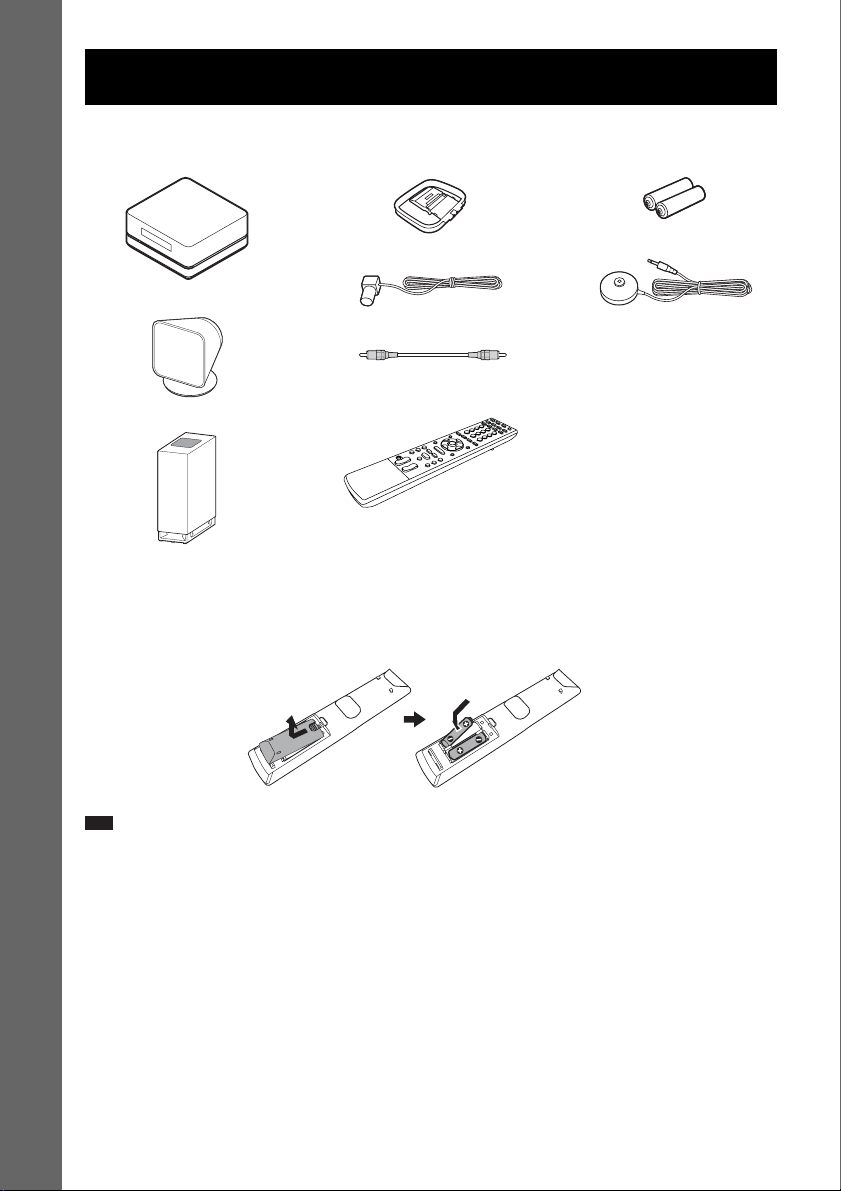
Unpacking
• Control unit (1)
• AM loop antenna (aerial) (1)
• R6 (size AA) batteries (2)
Getting Started
•Speakers (5)
•Subwoofer (1)
• FM wire antenna (aerial) (1)
• Video Cord (1)
• Remote Commander
(remote) (1)
• Calibration microphone (1)
• Brackets (5)
• Wrench (1)
• Operating Instructions
• Quick Start Guide (card) (1)
Inserting batteries into the remote
You can control the system using the supplied remote. Insert two R6 (size AA) batteries by matching
the 3 and # ends on the batteries to the markings inside the compartment. To use the remote, point it
at the remote sensor on the control unit.
AB
Note
• Do not leave the remote in an extremely hot or humid place.
• Do not use a new battery with an old one.
• Do not drop any foreign object into the remote casing, particularly when replacing the batteries.
• Do not expose the remote sensor to direct sunlight or lighting apparatus. Doing so may cause a malfunction.
• If you do not intend to use the remote for an extended period of time, remove the batteries to avoid possible damage
from battery leakage and corrosion.
US
10
Page 11
p
Step 1: Positioning the
)
d
Speakers
For the best possible surround sound, all the
speakers other than the subwoofer should be
placed at the same distance from the listening
position (1). It is recommended that the
subwoofer should be placed (2).
Place speakers and subwoofer as illustrated
below.
Front speaker (L)
Center speaker
Subwoofer
2
1 1 1
Front speaker (R)
11
Using the subwoofer
efficiently
To reinforce the bass sound, place the subwoofer
possible close to a wall.
Close to a wall
Note
• If the subwoofer is to be placed ahead of the front
speaker, the distance should be less than 0.5 m
(1.6 ft).*
*
Getting Started
Surround speaker (L) Surround speaker (R
Ti
• You can also place the subwoofer either side, facing
the listening position.
• When you install th e speaker, the speaker face may be
unstable. In this case, use a commercially available
wire clamper or a commercially available tape, etc.,
to secure the speaker cord.
• You may not get the bass sound efficiently when the
subwoofer is placed outside (3). You need to adjust
the setting of the distance from the listening position.
33
continue
US
11
Page 12
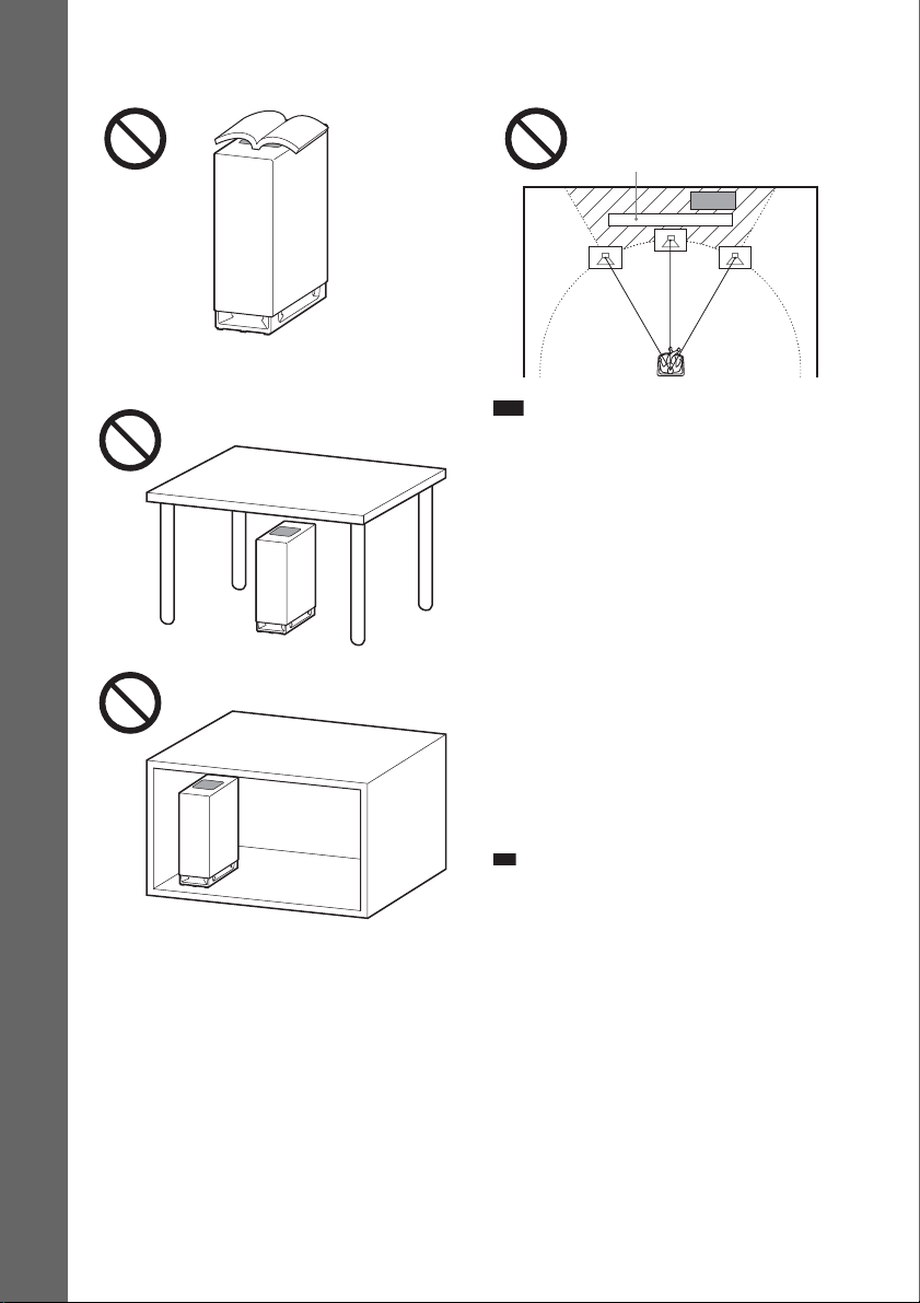
• Do not place objects on the top of the subwoofer
p
where the speaker unit is installed.
Getting Started
• Do not place the subwoofer under a desk or in a
cabinet, etc.
• Do not place the subwoofer back of the obstruction,
such as TV, etc. Middle range sound will fall.
TV etc.
Note
• Do not set the speakers in an inclined position.
• Do not place the speakers in locations that are:
– Extremely hot or cold
– Dusty or dirty
–Very humid
– Subject to vibrations
– Subject to direct sunlight
• Use caution when placing the speakers and/or
speaker stands (not supplied) that are attached to the
speakers on a specially treated (waxed, oiled,
polished, etc.) floor, as staining or discoloration may
result.
• When cleaning, use a soft cloth such as a cleaning
cloth for glasses.
• Do not use any type of abrasive pad, scouring
powder, or solvent such as alcohol or benzine.
• Image distortion on the TV screen may occur
depending on the location of the subwoofer. In this
case, place the subwoofer away from the TV.
Ti
• When you change the position of the speakers, Sony
recommends that you change the s ettings. For details,
see “Calibrating the Appropriate Settings
Automatically” (page 77).
US
12
Page 13
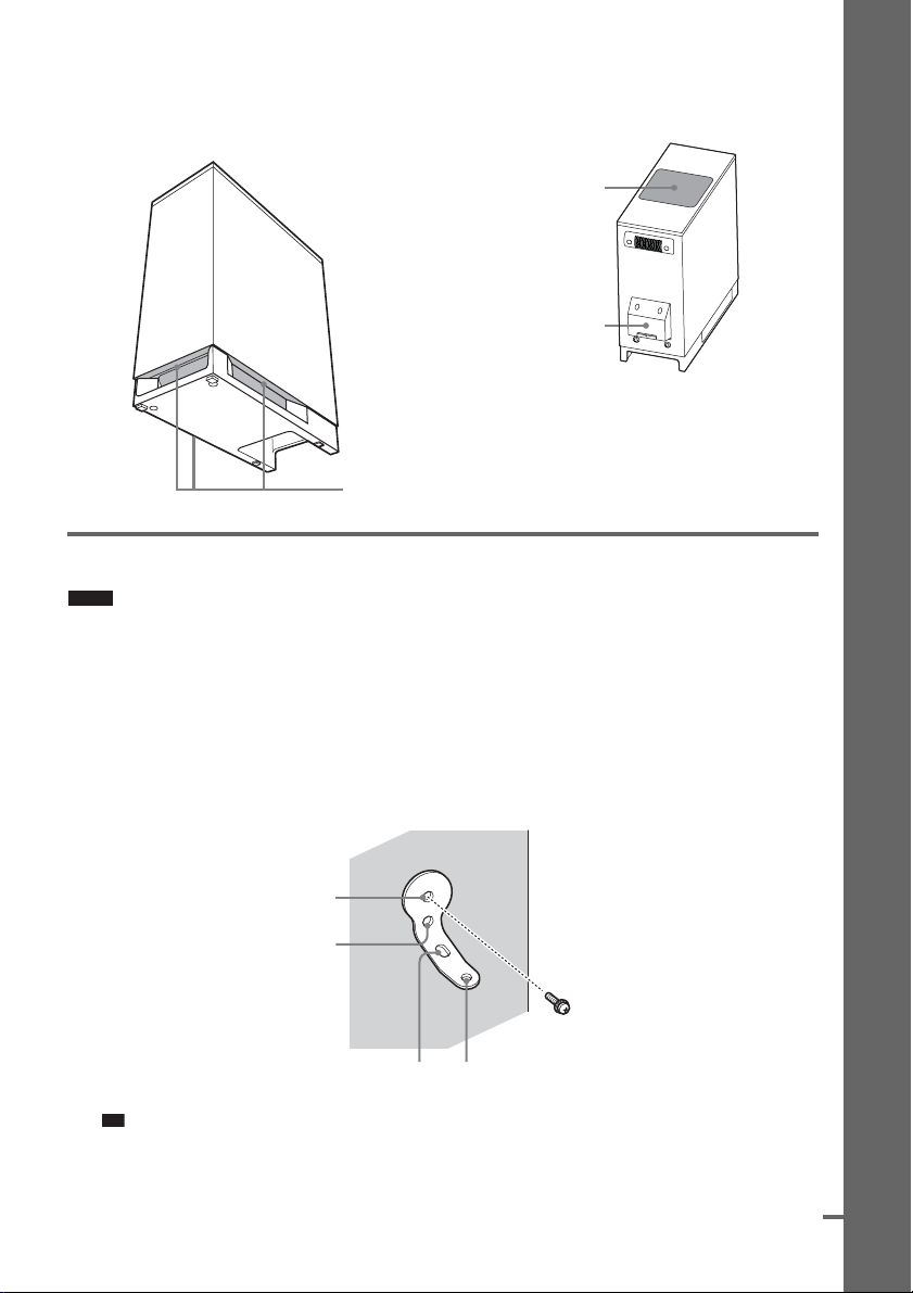
Note on handling the subwoofer
p
d
• Do not place your hand into the slit of the subwoofer
when lifting it. The speaker driver may be damaged.
When lifting, hold the bottom of the subwoofer.
Subwoofer
Slits
• Do not hold the EZW-T100 slot when lifting the
subwoofer.
• Do not push the top of the subwoofer where the
speaker unit is installed.
Speaker unit
EZW-T100 slot
Installing the speakers on a wall
Caution
• Contact a screw shop or installer regarding the wall material or screws to be used.
• Use screws that are suitable for the wall material and strength. As a plaster board wall is especially fragile, attach
the screws securely to a beam and fasten them to the wall. Install the speakers on a vertical and flat wall where
reinforcement is applied.
• Sony is not responsible for accident or damage caused by improper installation, insufficient wall strength or
improper screw installation, natural calamity, etc.
Getting Started
1 Prepare screws (not supplied) that are suitable for the holes of the bracket.
2 Secure the bracket to the wall using hole 1.
1
2
34
Ti
• To prevent the speaker from rotating, use the hole 2, too.
continue
13
US
Page 14

3 Remove the rear cap using the wrench (supplied), and remove the speaker pedestal
using a screwdriver (+) (not supplied).
Wrench (supplied)
Getting Started
Rear cap
4 Push A with the supplied wrench (1), and then remove the speaker cords (2).
(2)
(1)
When the lever is down, the
speaker cords are locked.
A
5 Thread the speaker cords through hole 3.
3
When the lever is up, the
speaker cords can be removed.
14
US
Page 15
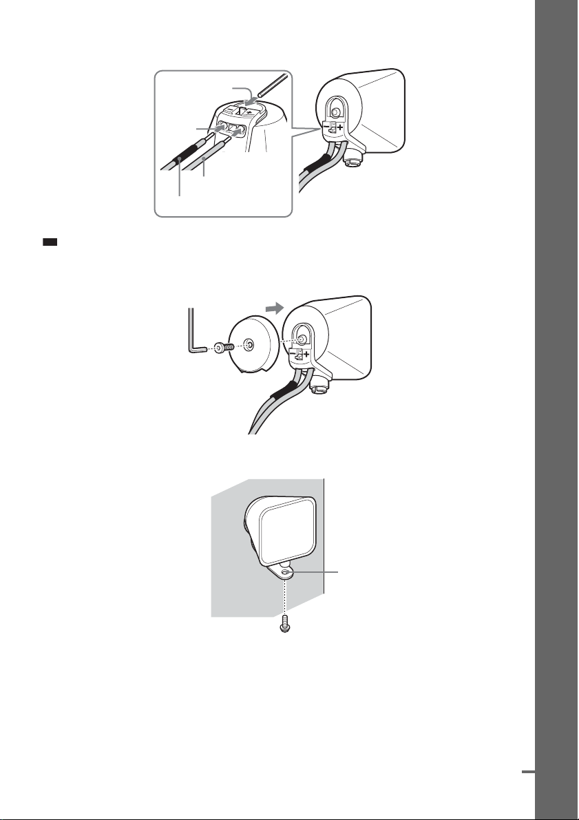
6 Reconnect the detached speaker cords, matching 3/# to the appropriate speaker
p
d
terminals (1), and then push the lever down completely (2).
(2)
(1)
3
#
Ti
• If it is difficult to push the lever down, use the wrench (supplied).
7 Reattach the rear cap using the wrench (supplied).
Getting Started
8 Secure the speaker to the bracket with the screw in Step 3 using hole 4.
4
continue
15
US
Page 16
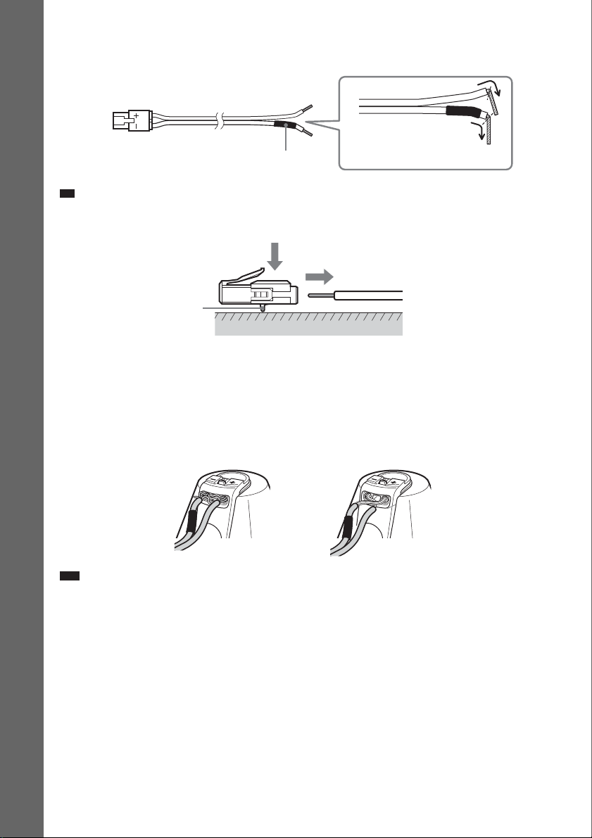
About connecting speaker cord
p
The connectors of the speaker cords are the same color as the jacks to be connected.
3
Do not catch the
speaker cords
insulation in the speaker
terminals.
Getting Started
#
Black
Ti
• You can remove the speaker cords from the connector. With the catch facing down, press and hold the connector
down against a flat surface (1) and remove the speaker cords from the connector (2).
(1)
(2)
Catch
To avoid short-circuiting the speakers
Short-circuiting of the speakers may damage the system. To prevent this, be sure to follow these
precautions when connecting the speakers. Make sure the bare wire of each speaker cord does not touch
another speaker terminal or the bare wire of another speaker cord, such as shown below.
Stripped cords are touching each
other due to excessive removal of
insulation.
Note
Stripped speaker cord is
touching another speaker
terminal.
Be sure to match the speaker cords to the appropriate speaker terminals: 3 to +, and # to –. If the cords
are reversed, the sound will lack bass and may be distorted.
US
16
Page 17
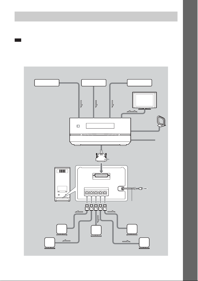
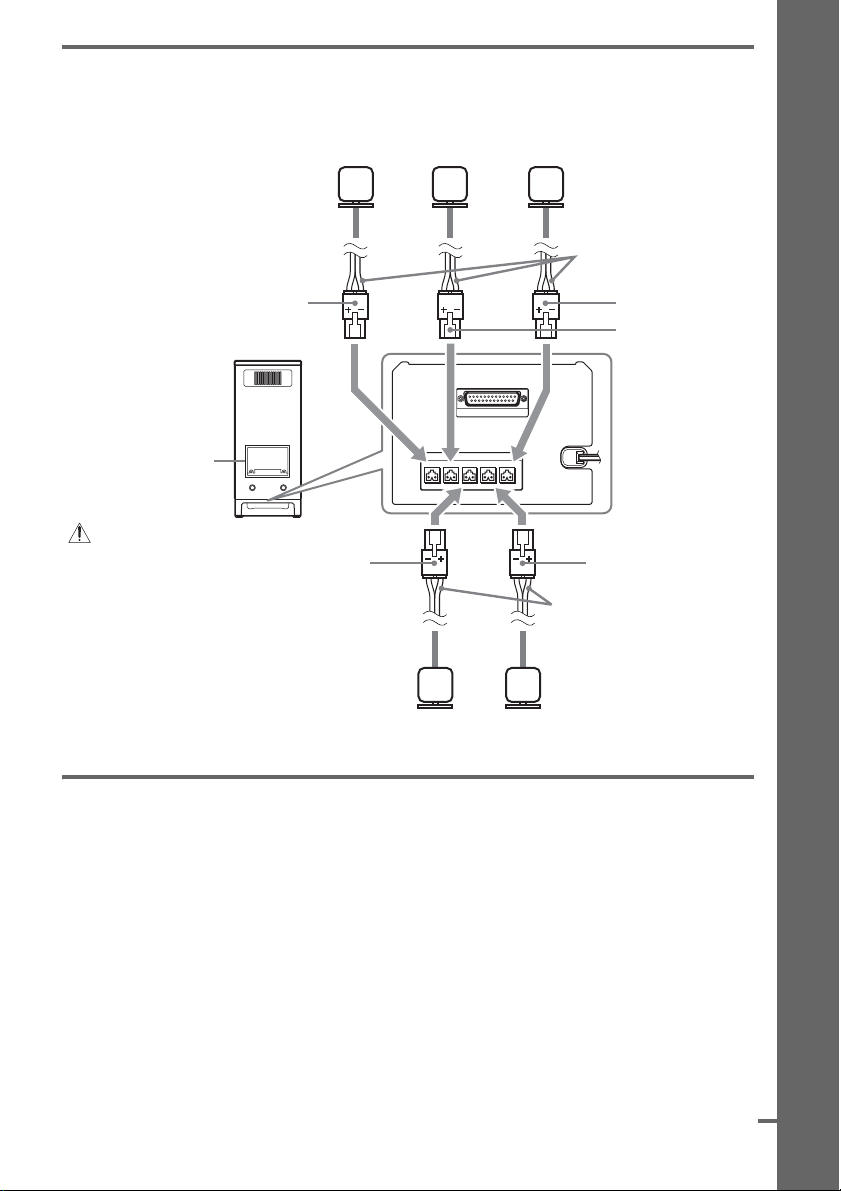
Step 2: Connecting the System
See the connection diagram below, and read the additional information from 1 to 6 on the following
pages.
Note
• Be sure to make connection securely to avoid hum and noise.
• When you connect another component with a volume control, turn up the volume of the other components to a level
where sound is not distorted.
Getting Started
4 VCR, digital
satellite receiver,
or PlayStation,
etc.
Rear of the
subwoofer
4 Portable audio source
Front of the control unit
Bottom of the
subwoofer
SPEAKER
SYSTEM CONTROL
ONLY FOR SS-IS15
ONLY FOR HCD-IS50
CENTERSUR LSUR RFRONT LFRONT R
4 DIGITAL MEDIA
PORT adapter
3 TV
5 AM loop
antenna (aerial)
5 FM wire antenna
(aerial)
1 Plug
6 AC power cord (mains lead)
2 Front
speaker (R)
2 Front speaker (L)
2 Surround
speaker (R)
2 Center
speaker
2 Surround speaker (L)
17
US
Page 18
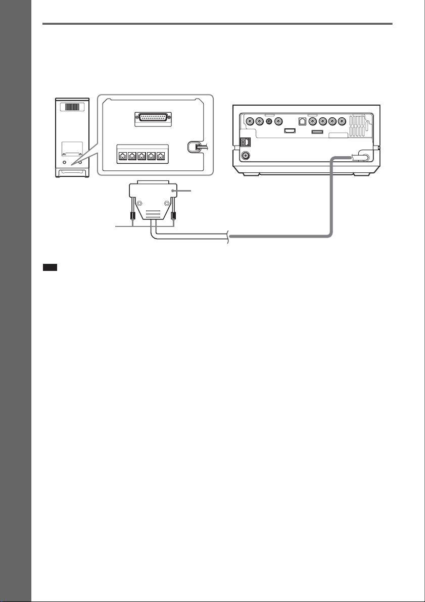
1 Connecting the Control unit
Connect the system connector of the control unit to the SYSTEM CONTROL terminal on the bottom
of the subwoofer.
Insert the plug of the SYSTEM CONTROL cord, then secure the screws of the plug.
Bottom of the subwoofer
Rear of the control unit
Getting Started
Rear of the
subwoofer
SPEAKER
SYSTEM CONTROL
ONLY FOR SS-IS15
ONLY FOR HCD-IS50
DMPORT
CENTERSUR LSUR RFRONT LFRONT R
Plug
Screws
Note
SYSTEM CONTROL cord
• Before connecting the control unit, place the subwoofer on a stable work surface that is larger than the subwoofer.
• Be sure to place a soft cloth on the work surface to avoid damaging the surface of the subwoofer.
18
US
Page 19
2 Connecting the Speakers
d
Connect the connectors of the speaker cords to the corresponding SPEAKER jacks. The connectors of
the speaker cords has the same color as the jacks to be connected.
Center speakerFront speaker (R) Front speaker (L)
Speaker cords
Getting Started
Red
Rear of the
subwoofer
EZW-T100 slot
(For details, see “Using
an S-AIR Product”
(page 63).
CAUTION
Please do not remove
the screws before
installing the EZW-T100.
3 Connecting the TV
Use the parts as follows:
• Video cord (1)
SYSTEM CONTROL
ONLY FOR HCD-IS50
SPEAKER
ONLY FOR SS-IS15
CENTERSUR LSUR RFRONT LFRONT R
Gray Blue
Speaker cords
Surround speaker (L)Surround speaker (R)
Green
White
Bottom of the
subwoofer
To listen to TV sound from the speakers of the system, connect the TV and the system with the audio
cord (not supplied) (A).
For video output to your TV, check the video input jacks of the TV, and select connection method A,
B, or C. Picture quality improves in order from A (standard) to C (HDMI).
When the TV has the digital optical or coaxial output jack, you can improve sound quality by
connecting with the digital cord (B).
continue
19
US
Page 20

Getting Started
p
Audio cord
(not supplied)
White
Red
Digital optical cord
(not supplied)
To the AUDIO OUT jacks of
the TV
To the digital optical output
jack of the TV
Rear of the control unit
DMPORT
HDMI** cable
(not supplied)
To the HDMI IN jack
Video cord
(supplied)
To the VIDEO IN jack of
the TV
Component video cord
(not supplied)*
R
/C
R
P
B
/C
B
P
Green
Blue
Red
of the TV
To the COMPONENT VIDEO IN
jacks of the TV
* If your TV accepts progressive format signals, use this connection and set the output signal of the system to
progressive format (page 28).
** HDMI (High-Definition Multimedia Interface)
If your TV has the HDMI jack, use this connection and select the type of output signal (page 27).
Note
• During the “DMPORT” function, video signal is not output from the HDMI OUT and COMPONENT VIDEO OUT
jacks.
• The system can accept both digital and analog signals. Digital signals have priority over analog signals. If the digital
signal ceases, the analog signal will be processed after 2 seconds.
• When connecting the HDMI cable, make sure that the direction of jacks are the same.
• When connecting the digital optical cord, insert the connector until it clicks into place.
Ti
• You can connect another component, such as a VCR, digital satellite receiver, or PlayStation, to the TV AUDIO
IN jacks (A) or TV DIGITAL IN OPTICAL jack (B) instead of the TV.
US
20
Page 21
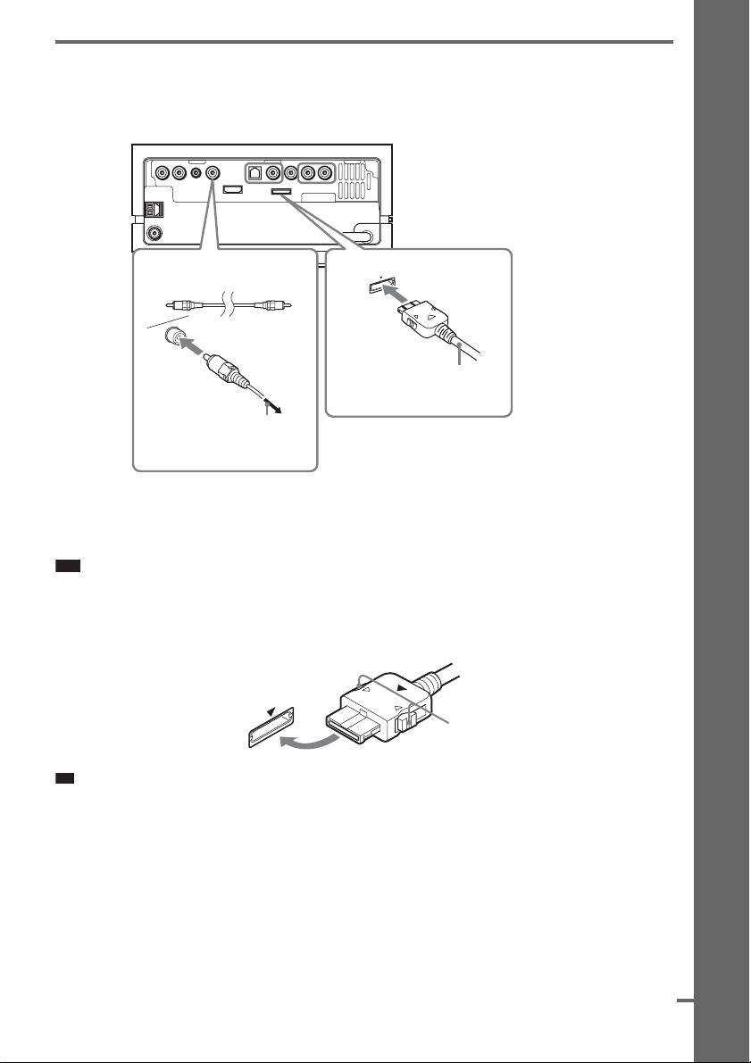
4 Connecting the other components
p
d
You can enjoy the connected component using the speakers of the system.
Rear of the control unit
DMPORT
Getting Started
Digital coaxial cord
B
(not supplied)
To the digital coaxial output
jack of another component
(e.g.: digital satellite receiver)
A
DIGITAL MEDIA PORT adapter
To connect the DIGITAL MEDIA PORT adapter
Connect the DIGITAL MEDIA PORT adapter to the DMPORT jack. For details, see “Using the
DIGITAL MEDIA PORT Adapter” (page 62).
Note
• Connect the DIGITAL MEDIA PORT adapter so that the V marks are aligned. When disconnecting, pull out while
pressing A.
• Do not connect or disconnect the DIGITAL MEDIA PORT adapter to/from the control unit while the system is
turned on.
A
Ti
• You can assign a digital sound input corresponding with the function “TV” and “SAT/CABLE.” For details,
see [DIGITAL IN] (page 84).
continue
US
21
Page 22
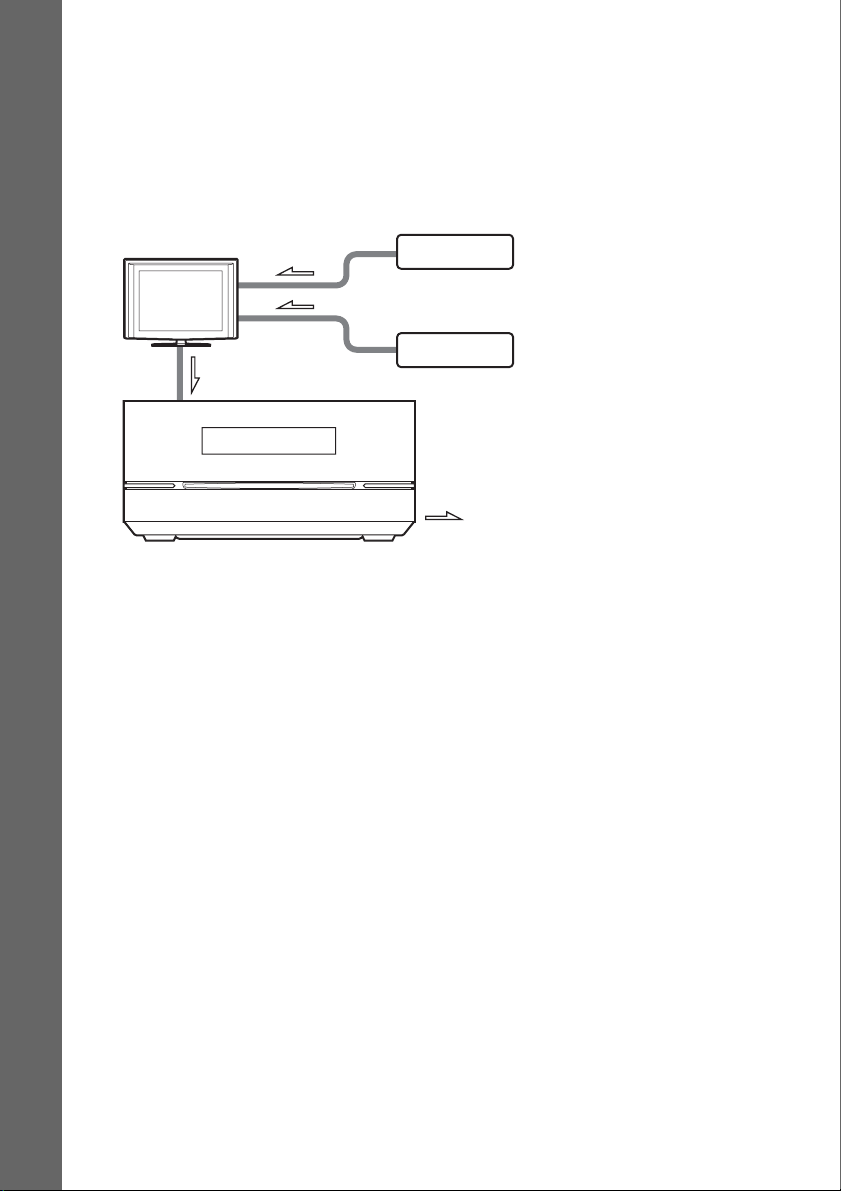
Wireless system option
By using an S-AIR product (not supplied), you can enjoy wireless performance by transmission from
the system. For details, see “Using an S-AIR Product” (page 63) or refer to the operating instructions
of the S-AIR product.
If your TV has multiple audio/video inputs
You can enjoy the sound with the speakers of the system through the connected TV. Connect the
components as follows.
Getting Started
TV
Control unit
VCR, digital satellite receiver
or PlayStation, etc.
VCR, digital satellite receiver
or PlayStation, etc.
:Signal flow
Select the component on the TV. For details, refer to the operating instructions of the TV.
If the TV does not have multiple audio/video inputs, a switcher will be necessary to receive the sound
from more than two components.
22
US
Page 23

5 Connecting the Antenna (Aerial)
p
AM loop antenna (aerial) (supplied)
A
B
Note
• Cord (A) or cord (B) can be connected to
either terminal.
Rear of the control unit
FM wire antenna (aerial)
(supplied)
Getting Started
DMPORT
Note
• Keep the AM loop antenna (aerial) and cord away from the system or other AV components, as noise may result.
• Be sure to fully extend the FM wire antenna (aerial).
• After connecting the FM wire antenna (aerial), keep it as horizontal as possible.
Ti
• Adjust the direction of the AM loop antenna (aerial) for best AM broadcast sound.
• If you have poor FM reception, use a 75-ohm coaxial cable (not supplied) to connect the control unit to an outdoor
FM antenna (aerial) as shown below.
Outdoor FM
Control unit
antenna (aerial)
AM
ANTENNA
FM 75
COAXIAL
23
US
Page 24

6 Connecting the AC power cord (mains lead)
Before connecting the AC power cord (mains lead) of the subwoofer to a wall outlet (mains), connect
all the speakers to the subwoofer (page 19).
Rear of the subwoofer
Getting Started
To a wall outlet
(mains)
AC power cord
(mains lead)
Note
• After connecting the AC power cord (mains lead), wait about 20 seconds before turning on the power by pressing
"/1.
24
US
Page 25

Step 3: Performing the
d
Quick Setup
4 Press without inserting a disc.
The Setup Display for selecting the
language used in the on-screen display
appears on the TV screen.
Getting Started
Follow the steps below to make the basic
adjustments for using the system.
Note
• When you connect the system and the TV with the
component video cord (not supplied) or HDMI cable
(not supplied), you need to set the type of video
output for matching your TV. For details, see “Setting
the type of video output to match your TV” (page 27).
"/1
C/X/x/c,
DISPLAY
1 Turn on the TV.
2 Press [/1.
The system turns on.
Note
• Make sure that the function is set to “DVD”
(page 32).
3 Switch the input selector on your TV so
that the signal from the system
appears on the TV screen.
[Press [ENTER] to run QUICK SETUP.]
appears at the bottom of the TV screen. If
this message does not appear, recall the
Quick Setup display (page 27) and perform
again.
LANGUAGE SETUP
OSD:
MENU:
AUDIO:
SUBTITLE:
ENGLISH
ENGLISH
FRENCH
SPANISH
PORTUGUESE
5 Press X/x to select a language.
The system displays the menu and subtitles
in the selected language.
6 Press .
The Setup Display for selecting the aspect
ratio of the TV to be connected appears.
VIDEO SETUP
TV TYPE:
PROGRESSIVE
4:3 OUTPUT:
BLACK LEVEL:
BLACK LEVEL
PAUSE MODE:
(COMPONENT OUT)
4:3 LETTER BOX
(COMPONENT OUT)
16:9
16:9
:
4:3 PAN SCAN
OFF
:
AUTO
7 Press X/x to select the setting that
matches your TV type.
x If you have a wide-screen TV or a 4:3
standard TV with a wide-screen mode
[16:9] (page 80)
x If you have a 4:3 standard TV
[4:3 LETTER BOX] or [4:3 PAN SCAN]
(page 80)
8 Press .
9 Connect the calibration microphone to
the ECM-AC2 jack on the rear of the
control unit.
Set up the calibration microphone at the ear
level using a tripod, etc. (not supplied).
The front of each speaker should face the
calibration microphone, and there should be
no obstruction between the speakers and the
calibration microphone.
continue
25
US
Page 26
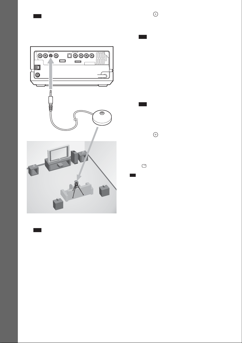
Note
p
• The ECM-AC2 jack is used for the supplied
calibration microphone only. Do not connect
other microphones.
Rear of the control unit
Getting Started
To ECM-AC2 jack
10Press C/c to select [YES].
Note
• Make sure that the headphones are not
connected to the surround amplifier (not
supplied, page 63). You cannot operate
following steps with the headphones connected.
DMPORT
Calibration microphone
11 Press .
[AUTO CALIBRATION] starts. Be quiet
during the measurement.
Note
• Loud test sound is output when [AUTO
CALIBRATION] starts. You cannot turn the
volume down. Give consideration to children
and neighbors.
• Avoid being in the measurement area and
making noise during the measurement (which
takes about 1 minute), as it may interfere with
measurement.
12 Unplug the calibration microphone and
press C/c to select [YES].
Note
• The environment of the room in which the
system is installed may affect measurements.
• If measurement fails, follow the message then
retry [AUTO CALIBRATION].
13 Press .
Quick Setup is finished. All connections
and setup operations are complete.
To quit the Quick Setup
Press DISPLAY in any Step.
Ti
• If you cancel [AUTO CALIBRATION], perform the
speaker settings in “Settings for the Speakers”
(page 85).
• If you change the position of the speakers, reset the
speaker settings. See “Calibrating the Appropriate
Settings Automatically” (page 77).
• If you want to change any of the settings, see “Using
the Setup Display” (page 79).
• For details on [AUTO CALIBRATION] and the error
messages of [AUTO CALIBRATION], see
“Calibrating the Appropriate Settings Automatically”
(page 77).
US
26
Page 27
To recall the Quick Setup display
d
1 Press FUNCTION repeatedly until “DVD”
appears in the front panel display.
2 Press DISPLAY when the system is in
stop mode.
The Control Menu display appears on the TV
screen.
3 Press X/x to select [SETUP], then
press .
The options for [SETUP] appear.
9 4 ( 9 9 )
CUSTOM
BNR
1 ( 1 )
T
0 : 0 1 : 0 8
CUSTOM
QUICK
DVD VIDEO
4 Press X/x to select [QUICK], then press .
The Quick Setup display appears.
Setting the type of video
output to match your TV
Depending on the connection of the TV
(page 19), select the type of video output of the
system.
To select the type of video signal
output from the HDMI OUT jack
When you connect the control unit and the TV
with the HDMI cable, select the type of video
signals output from HDMI OUT jack.
For details, refer also to the operating
instructions supplied with the TV/projector, etc.
1 Press FUNCTION repeatedly until
“DVD” appears in the front panel
display.
2 Press DISPLAY while the system is
in stop mode.
The Control Menu display appears on the
TV screen.
3 Press X/x to select [SETUP],
then press .
The options for [SETUP] appear.
4 Press X/x to select [CUSTOM], then
press .
The Setup Display appears.
5 Press X/x to select [HDMI SETUP], then
press .
The options for [HDMI SETUP] appear.
6 Press X/x to select [HDMI
RESOLUTION], then press .
7 Press X/x to select the desired setting,
then press .
• [AUTO(1920×1080p)]: The system outputs the
optimal video signal for the connected TV.
• [1920×1080i]: The system outputs 1920 ×
1080i* video signals.
• [1280×720p]: The system outputs 1280 × 720p*
video signals.
•[720×480p]: The system outputs 720 × 480p*
video signals.
* i: interlace, p: progressive
Getting Started
continue
27
US
Page 28

Does your TV accept progressive
signals?
Progressive is the method for displaying TV
images which reduces flickering and sharpens
the image. To use this method, you need to
connect to a TV that accepts progressive signals.
1 Press FUNCTION repeatedly until
Getting Started
“DVD” appears in the front panel
display.
2 Press DISPLAY while the system is
in stop mode.
The Control Menu display appears on the
TV screen.
3 Press X/x to select [SETUP],
then press .
The options for [SETUP] appear.
4 Press X/x to select [CUSTOM], then
press .
The Setup Display appears.
5 Press X/x to select [VIDEO SETUP],
then press .
The options for [VIDEO SETUP] appear.
6 Press X/x to select [PROGRESSIVE
(COMPONENT OUT)], then press .
7 Press X/x to select the desired setting,
then press .
[OFF]: The system does not output
progressive signals. Select this setting
when:
– your TV does not accept progressive signals, or,
– your TV is connected to jacks other than the
COMPONENT VIDEO OUT jacks.
[ON]: The system outputs progressive
signals. Select this setting when:
– your TV accepts progressive signals, and,
– the TV is connected to the COMPONENT
VIDEO OUT jacks.
When you select [ON], the confirmation
display appears. Follow the Steps below.
8 Press C/c to select [START], then
press .
The system outputs the progressive signal
for 5 seconds. Check that the screen is
displayed correctly.
9 Press C/c to select [YES], then press
.
The system outputs the progressive signal.
When you select [NO], the system does not
output the progressive signal.
28
US
Page 29
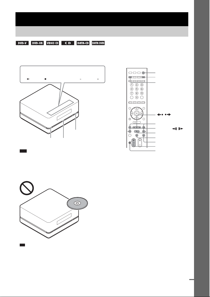
Basic Operations
p
d
Playing a Disc
Depending on the DVD VIDEO or VIDEO CD, some operations may be different or restricted.
Refer to the operation details supplied with your disc.
Basic Operations
Soft-touch buttons
FUNCTION VOLUME
Z
Disc slot
"/1
Note
• Soft-touch buttons function by touching lightly. Do not press
them strongly.
• Do not place objects on the top of the control unit. Doing so
may activate the soft-touch buttons or deactivate the buttons
of the control unit.
"/1
FUNCTION
Z
/
./>
m/M, /
H
X
x
VOLUME +/–
MUTING
Ti
• Soft-touch buttons function when they are lit up.
• You can select the way of displaying the soft-touch buttons
located on the top of the control unit (page 73).
continue
US
29
Page 30
1 Turn on your TV.
p
2 Switch the input selector on the TV to this system.
3 Press "/1.
The system turns on.
Unless the mode of the system is set to “DVD,” press FUNCTION on the remote or FUNCTION
(soft-touch button) on the control unit to select “DVD.”
“No Disc” appears in the front panel display and the system is ready for loading the disc.
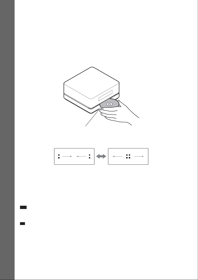
4 Load a disc.
Push the disc into the disc slot until the disc is pulled in automatically.
Basic Operations
Labeled side facing to upper surface
The disc is drawn into the control unit automatically and the following indication appears in the
front panel display.
5 Press H on the remote, or touch N (soft-touch button) on the control unit.
The system starts playback (continuous play).
6 Adjust the VOLUME +/– on the remote or touch the VOLUME +/– (soft-touch button) on
the control unit.
The volume level appears on the TV screen and in the front panel display. Depending on the system
status, the volume level may not appear on the
Note
• When you set the Control for HDMI function to on, the TV that is connected to the control unit with an HDMI cable
can be sync-operated with the system. For details, see page 59.
Ti
• When you connect the system and TV with an HDMI cable, you can operate them simply using the Control for
HDMI function. For details, see page 59.
US
30
TV screen.
Page 31

To save the power in standby mode
Press "/1 while the system turns on, then the system enters standby mode. To cancel standby mode,
press "/1 once.
To enter power standby mode, make sure that the system is in the following status.
– [CONTROL FOR HDMI] is set to [OFF] (page 60).
– “S-AIR STBY” is set to “OFF” (page 66).
Note
• When the system is turned off, do not push a disc into the control unit.
Additional operations
To Press
Stop x
Pause X
Resume play after pause X / H on the remote or N (soft-touch button) on the control unit.
Go to the next chapter, track, or scene1)>
Go back to the preceding cha pter, track,
1)
or scene
Turn off the sound temporarily MUTING. To cancel muting, press it again or VOLUME + to adjust the
Stop play and remove the desired disc Z
Locate a point quickly by playing a
disc in fast forward or fast reverse
1)2)
(Scan)
Watch frame by frame (Slow-motion
3)
Play)
Play one frame at a time (Freeze
3)
Frame)
Replay the previous scene
(10 seconds before)
Briefly fast forward the current scene
(30 seconds after)
1)
Except for JPEG image files.
2)
Scan speeds may differ with some discs.
3)
DVD VIDEO, DVD-R, DVD-RW, VIDEO CD only.
4)
Except for VIDEO CDs.
5)
DVD VIDEO/DVD-RW/DVD-R only.
6)
DVD VIDEO/DVD-RW/DVD-R/DVD+RW/DVD+R only.
Note
5)
6)
• You may not be able to use the instant replay or instant advance function with some scenes.
. twice in a second. When you press . once, you can go to the
beginning of the current chapter, track or scene.
sound volume.
M/ or /m while playing a disc. Each time you press M/
or /m during scanning, the playback speed changes. To return to
normal speed, press H. Actual speeds may differ with some discs.
M/ or /m4) while the system is in pause mode. Each time you
press M/ or /m4) during Slow-motion Play, the playback
speed changes. Two speeds are available. To return to normal playback
speed, press H.
to go to the next frame while the system is in pause mode. Press
to go to the preceding frame while the system is in pause mode (DVD
VIDEO/DVD-VR/DVD-R/DVD-RW/DVD+R/DVD+RW only).
To return to normal playback, press H.
(instant replay) during playback.
(instant advance) during playback.
Basic Operations
31
US
Page 32

p
Enjoying the Radio or Other Components
Selecting the connected component
You can use a TV, VCR, or other components connected to the TV or SAT/CABLE jacks on the rear
of the control unit. Refer to the operating instructions supplied with the components for further
information.
Basic Operations
FUNCTION
Press FUNCTION repeatedly until the desired function name appears in the front panel
display.
Each time you press FUNCTION, the mode of the system changes in the following sequence.
DVD t FM t AM t TV t SAT/CABLE t DMPORT t DVD t …
Ti
• You can assign a digital sound input corresponding with the function “TV” and “SAT/CABLE”. For details, see
[DIGITAL IN] (page 84).
Note
• When you use both the TV (AUDIO IN) jacks (analog connection) and TV (DIGITAL IN OPTICAL) jack (digital
connection) at the same time, the digital connection takes priority.
US
32
Page 33

Changing the input level of the sound from connected
components
Distortion may occur when you listen to a component connected to the TV (AUDIO IN) jacks on the
rear of the control unit. This is not a malfunction and will depend on the component connected.
To prevent distortion, reduce the input level on the control unit.
FUNCTION
X/x/c,
SYSTEM
MENU
1 Press FUNCTION repeatedly until “TV” appears in the front panel display.
2 Press SYSTEM MENU.
3 Press X/x repeatedly until “ATTENUATE” appears in the front panel display, then press
or c.
4 Press X/x to select a setting.
•“ATT ON”: You can attenuates the input level. The output level is changed.
• “ATT OFF”: Normal input level.
5 Press .
The setting is made.
6 Press SYSTEM MENU.
The system menu turns off.
Note
• “ATTENUATE” appears only when the function is set to the “TV” function.
Basic Operations
33
US
Page 34

Enjoying Sound from all Speakers
You can enjoy TV or VCR sound from all the speakers in this system.
For details, see “Connecting the TV” (page 19) and “Connecting the other components” (page 21).
FUNCTION
Basic Operations
X/x/c,
SYSTEM
MENU
1 Press FUNCTION repeatedly until “TV” or “SAT/CABLE” appears in the front panel
display.
2 Press SYSTEM MENU.
3 Press X/x repeatedly until “DEC. MODE” appears in the front panel display, then press
or c.
4 Press X/x repeatedly until the decoding mode you want appears in the front panel
display.
When you want to output the TV sound or stereo sound of a 2 channel source from all speakers,
select “PLII MOVIE” or “PLII MUSIC” decoding mode.
For details, see page 52.
5 Press .
The setting is made.
6 Press SYSTEM MENU.
The system menu turns off.
Note
• When you set the [CONTROL FOR HDMI] setting in [HDMI SETUP] to [ON] (page 60), the System Audio
Control function is activated and no sound may be output from the TV. For details, see page 61.
• When you use both the TV (AUDIO IN) jacks (analog connection) and TV (DIGITAL IN OPTICAL) jack (digital
connection) at the same time, the digital connection takes priority.
• Depending on your TV, you may need to turn off your TV’s speaker to enjoy surround sound of the system.
34
US
Page 35

p
Various Functions for Playing Discs
Searching for a Title/
Chapter/Track/Scene,
3 Press .
[** (**)] changes to [– – (**)].
98( 99)
13( 99)
T 0: 03: 17
DVD VIDEO
etc.
You can search a DVD VIDEO/DVD-VR by
title or chapter, and you can search a VIDEO
CD/CD/DATA CD/DATA DVD by track,
index, or scene. For a DATA CD/DATA DVD,
you can search by folder or file. As titles and
tracks are assigned unique numbers on the disc,
you can select the desired title or track by
entering its number. Or, you can search for a
scene using the time code.
1 Press DISPLAY. (When playing a
DATA CD/DATA DVD with JPEG image
files, press DISPLAY twice.)
The Control Menu display appears on the
TV screen.
2 Press X/x to select the search method.
Example: when you select
[CHAPTER]
[** (**)] is selected (** refers to a number).
The number in parentheses indicates the
total number of titles, chapters, tracks,
indexes, scenes, folders or files.
98( 99)
13( 99)
T 0: 03: 17
Selected row
DVD VIDEO
Various Functions for Playing Discs
4 Press X/x or the numeric buttons to
select the desired title, chapter, track,
index, scene, etc.
If you make a mistake
Cancel the number by pressing CLEAR,
then select another number.
5 Press .
The system starts playback from the
selected number.
Ti
• When the Contro l Menu display is turned off, you can
search for a chapter (DVD VIDEO/DVD-R/DVDRW), track (VIDEO CD/CD), or file (DATA CD/
DATA DVD) by pressing the numeric buttons and
.
To search for a scene using the
time code (DVD VIDEO and DVDVR mode only)
1 In Step 2, select [TIME].
[T **:**:**] (playing time of the current title)
is selected.
2 Press .
[T **:**:**] changes to [T --:--:--].
3 Input the time code using the numeric
buttons.
For example, to find the scene at 2 hours,
10 minutes, and 20 seconds after the
beginning, just press “2, 1, 0, 2, 0”
([2:10:20]).
4 Press .
Note
• You cannot search for a scene on a DVD+R/
DVD+RW using the time code.
US
35
Page 36

p
p
Resuming Playback from the Point Where You Stopped the Disc
(Resume Play)
When you stop the disc, the system remembers
the point where you pressed x and “Resume”
appears in the front panel display. As long as
you do not remove the disc, Resume Play will
work even if the system is set to standby mode
by pressing "/1.
1 While playing a disc, press x to stop
playback.
“Resume” appears in the front panel
display.
2 Press H.
The system starts playback from the point
where you stopped the disc in Step 1.
Note
• Depending on where you stop the disc, the system
may not resume playback from exactly the same
point.
• The point where you stopped playing may be cleared
when:
– you eject the disc.
– the system enters standby mode (DATA CD/
DATA DVD only).
– you change or reset the settings on the Setup
Display.
– you change the function by pressing FUNCTION.
– you disconnect the AC power cord (mains lead).
– you change the parental control level.
• For a DVD-VR, VIDEO CD, CD, DATA CD, and
DATA DVD, the system remembers the resume
playback point for the current disc.
• Resume Play does not work during Program Play and
Shuffle Play.
• This function may not work properly with some
discs.
Ti
• To play from the beginning of the disc, press x twice,
then press H.
To enjoy a disc that is played
before by resume playback
(Multi-disc Resume)
(DVD VIDEO, VIDEO CD only)
This system recalls the point where you stopped
the disc the last time it was played and resumes
playback from that point the next time you insert
the same disc. When the resume playback
memory is full, the resume playback point for
the earliest disc is deleted.
To activate this function, set [MULTI-DISC
RESUME] in [SYSTEM SETUP] to [ON]. For
details, see “[MULTI-DISC RESUME] (DVD
VIDEO/VIDEO CD only)” (page 85).
Note
• If [MULTI-DISC RESUME] in [SYSTEM SETUP]
is set to [OFF] (page 85), the resume point is cleared
when you change the function by pressing
FUNCTION.
• This system can store at least 10 resume playback
points.
Ti
• To play from the be ginning of the disc, press x twice,
then press H.
US
36
Page 37

Creating Your Own
d
Program
(Program Play)
You can play the contents of a disc in the order
you want by arranging the order of the tracks on
the disc to create your own program. You can
program up to 99 tracks.
1 Press DISPLAY.
The Control Menu display appears on the
TV screen.
2 Press X/x to select
[PROGRAM], then press .
The options for [PROGRAM] appear.
3 Press X/x to select [SET t], then
press .
Total time of the
programmed tracks
PROGRAM 0: 00:00
ALL CLEAR
1. TRACK
2. TRACK
3. TRACK
4. TRACK
5. TRACK
6. TRACK
7. TRACK
– – – –
– –
– –
– –
– –
– –
– –
T
01
02
03
04
05
06
Tracks recorded
on a disc
5 Select the track you want to program.
For example, select track [02].
Press X/x to select [02] under [T], then
press .
Selected track
PROGRAM 0: 03:51
ALL CLEAR
1. TRACK
2. TRACK
3. TRACK
4. TRACK
5. TRACK
6. TRACK
7. TRACK
Total time of the programmed tracks
02 – –
– –
– –
– –
– –
– –
– –
T
01
02
03
04
05
06
6 To program other tracks, repeat steps 4
to 5.
The programmed tracks are displayed in the
selected order.
7 Press H to start Program Play.
Program Play starts.
When the program ends, you can restart the
same program again by pressing H.
To return to normal play
Press CLEAR while the display for the program
setting is not displayed on the TV screen, or
select [OFF] in step 3. To play the same program
again, select [ON] in step 3 and press .
Various Functions for Playing Discs
4 Press c.
The cursor moves to the track row [T] (in
this case, [01]).
PROGRAM 0: 00:00
ALL CLEAR
1. TRACK
2. TRACK
3. TRACK
4. TRACK
5. TRACK
6. TRACK
7. TRACK
– – – –
– –
– –
– –
– –
– –
– –
T
01
02
03
04
05
06
continue
US
37
Page 38

To turn off the Control Menu
display
Press DISPLAY repeatedly until the Control
Menu display is turned off.
To change or cancel a program
1 Follow steps 1 to 3 of “Creating Your Own
Program”.
2 Press X/x to select the program number of
the track you want to change or cancel.
If you want to delete the track from the
program, press CLEAR.
3 Follow step 5 for new programming.
To cancel a program, select [--] under [T],
then press .
To cancel all of the tracks in the
programmed order
1 Follow steps 1 to 3 of “Creating Your Own
Program”.
2 Press X and select [ALL CLEAR].
3 Press .
Note
• When you press CLEAR to return to normal play,
Shuffle Play and Repeat Play are also canceled.
Playing in Random Order
(Shuffle Play)
You can play the contents on a disc in random
order. Subsequent Shuffle Play may produce a
different playing order.
Note
• Same song may be played repeatedly when you are
playing MP3 files.
1 Press DISPLAY during playback.
The Control Menu display appears on the
TV screen.
2 Press X/x to select [SHUFFLE],
then press .
The options for [SHUFFLE] appear.
3 Press X/x to select the item to be
shuffled.
x VIDEO CD/CD
•[OFF]: Off.
• [TRACK]: You can shuffle tracks on the
disc.
x During Program Play
•[OFF]: Off.
• [ON]: You can shuffle tracks selected in
Program Play.
x DATA CD/DATA DVD
•[OFF]: Off.
• [ON (MUSIC)]: You can shuffle MP3
files in the folder on the current disc.
When no folder is selected, the first folder
will play in random order.
4 Press .
Shuffle Play starts.
38
US
Page 39

To return to normal play
d
Press CLEAR or select [OFF] in step 3.
To turn off the Control Menu
display
Press DISPLAY repeatedly until the Control
Menu display is turned off.
Note
• You cannot use this function with a VIDEO CD and
Super VCD with PBC playback.
• When you press CLEAR to return to normal play,
Program Play and Repeat Play are also canceled.
Playing Repeatedly
(Repeat Play)
You can play the contents on a disc repeatedly.
You can use a combination of Shuffle Play or
Program Play modes.
1 Press DISPLAY during playback.
The Control Menu display appears on the
TV screen.
2 Press X/x to select [REPEAT],
then press .
The options for [REPEAT] appear.
3 Press X/x to select the item to be
repeated.
x DVD VIDEO/DVD-VR
•[OFF]: Off.
• [DISC]: You can repeat all of the titles on
the disc.
• [TITLE]: You can repeat the current title
on a disc.
• [CHAPTER]: You can repeat the current
chapter.
x VIDEO CD/CD
•[OFF]: Off.
• [DISC]: You can repeats all of the tracks
on the disc.
• [TRACK]: You can repeat the current
track.
x DATA CD/DATA DVD
•[OFF]: Off.
• [DISC]: You can repeat all of the folders
on the disc.
• [FOLDER]: You can repeat the current
folder.
• [TRACK] (MP3 files only): You can
repeat the current file.
x During Shuffle Play or Program Play
•[OFF]: Off.
• [ON]: You can repeat Shuffle Play or
Program Play.
Various Functions for Playing Discs
continue
39
US
Page 40

4 Press .
p
The item is selected.
To return to normal play
Press CLEAR or select [OFF] in step 3.
To turn off the Control Menu
display
Press DISPLAY repeatedly until the Control
Menu display is turned off.
Note
• You cannot use Repeat Play with a VIDEO CD and
Super VCD with PBC playback.
• When the system is playing a DATA CD/DATA
DVD which contains MP3 files and JPEG image
files, and their playing time is not the same, the audio
sound will not match the image.
• When [MODE (MUSIC, IMAGE)] is set to [IMAGE]
(page 50), you cannot select [TRACK].
• When you press CLEAR to return to normal play,
Program Play and Shuffle Play are also canceled.
Ti
• You can quickly display the [REPEAT] status. Press
REPEAT on the remote.
Using the DVD’s Menu
A DVD is divided into a lot of sections, which
make up a picture or music feature. These
sections are called “titles”. When you play a
DVD which contains several titles, you can
select the title you want using DVD TOP
MENU.
When you play a DVD that allows you to select
items such as the language for the subtitles and
the language for the sound, select these items
using DVD MENU.
1 Press DVD TOP MENU or DVD MENU.
The disc’s menu appears on the TV screen.
The contents of the menu vary depending
on the disc.
2 Press C/X/x/c or the numeric buttons
to select the item you want to play or
change.
3 Press .
To display the DVD’s menu on the
Control Menu display
1 Press DISPLAY during playback.
The Control Menu display appears on the
TV screen.
2 Press X/x to select [DISC
MENU], then press .
The options for [DISC MENU] appear.
3 Press X/x to select [MENU] or [TOP
MENU].
4 Press .
To turn off the Control Menu
display
Press DISPLAY repeatedly until the Control
Menu display is turned off.
US
40
Page 41

Changing the Sound
When the system is playing a DVD VIDEO or
DATA CD/DATA DVD recorded in multiple
audio formats (PCM, Dolby Digital, MPEG
audio, or DTS), you can change the audio
format. If the DVD VIDEO is recorded with
multilingual tracks, you can also change the
language.
With a VIDEO CD, CD, DATA CD, or DATA
DVD, you can select the sound from the right or
left channel and listen to the sound of the
selected channel through both the right and left
speakers.
Press AUDIO repeatedly during playback to
select the desired audio signal.
x DVD VIDEO
Depending on the DVD VIDEO, the choice of
language varies.
When 4 digits are displayed, they indicate a
language code. See “Language Code List”
(page 102) to confirm which language the code
represents. When the same language is
displayed two or more times, the DVD VIDEO
is recorded in multiple audio formats.
x DVD-VR
The types of sound tracks recorded on a disc are
displayed.
Example:
•[1: MAIN]
• [1: SUB] (sub sound)
• [1: MAIN+SUB] (main and sub sound)
•[2: MAIN]
•[2: SUB]
•[2: MAIN+SUB]
Note
• [2: MAIN], [2: SUB], and [2: MAIN+SUB] do not
appear when one audio stream is recorded on the disc.
(main sound)
x VIDEO CD/CD/DATA CD (MP3 file)/DATA
DVD (MP3 file)
•[STEREO]: The standard stereo sound
• [1/L]: The sound of the left channel
(monaural)
• [2/R]: The sound of the right channel
(monaural)
x Super VCD
•[1:STEREO]: The stereo sound of the audio
track 1
• [1:1/L]: The sound of the left channel of the
audio track 1 (monaural)
• [1:2/R]: The sound of the right channel of the
audio track 1 (monaural)
• [2:STEREO]: The stereo sound of the audio
track 2
• [2:1/L]: The sound of the left channel of the
audio track 2 (monaural)
• [2:2/R]: The sound of the right channel of the
audio track 2 (monaural)
Note
• While the system is playing a Super VCD on which
the audio track 2 is not recorded, no sound will come
out when you select [2:STEREO], [2:1/L], or [2:2/R].
Various Functions for Playing Discs
41
US
Page 42

Checking the audio signal
format
(DVD VIDEO only)
If you press AUDIO repeatedly during
playback, the format of the current audio signal
(PCM, Dolby Digital, DTS, etc.) appears as
shown below.
x DVD
Example:
Dolby Digital 5.1 channel
LFE (Low
Surround (L/R)
1: ENGLISH
Front (L/R) +
Center
Example:
Dolby Digital 3 channel
Front (L/R)
Frequency Effect)
DOLBY DIGITAL 3 / 2 .1
CL R
LFE
LS RS
Currently playing
program format
Surround
(Monaural)
Selecting [ORIGINAL] or [PLAY LIST] on a DVD-VR
This function is only available for DVD-VRs
with a playlist created.
1 Press DISPLAY while the system is
in stop mode.
The Control Menu display appears on the
TV screen.
2 Press X/x to select [ORIGINAL/
PLAY LIST], then press .
The options for [ORIGINAL/PLAY LIST]
appear.
3 Press X/x to select a setting.
• [PLAY LIST]: You can play the titles
created from [ORIGINAL] for editing.
• [ORIGINAL]: You can play the titles
originally recorded.
4 Press .
42
1:SPANISH
US
DOLBY DIGITAL 2 / 1
L R
S
Currently playing
program format
Page 43

p
Viewing Information About
d
the Disc
Viewing the playing time and
remaining time in the front
panel display
Press DISPLAY repeatedly.
Each time you press DISPLAY while playing
the disc, the front panel display changes
1 t 2 t ... t 1 t ...
Some displayed items may disappear after a few
seconds.
x DVD VIDEO/DVD-VR
1 Playing time of the current title
2 Remaining time of the current title
3 Playing time of the current chapter
4 Remaining time of the current chapter
5 Disc name
6 Title and chapter
x VIDEO CD (without PBC functions)/CD
1 Playing time of the current track
2 Remaining time of the current track
3 Playing time of the disc
4 Remaining time of the disc
5 Track name
6 Track and index
a)
VIDEO CD only.
x Super VCD
1 Playing time of the current track
2 Track text
3 Track and index number
x DATA CD (MP3 file) or DATA DVD
(MP3 file)
1 Playing time and current track number
2 Track (file) name
b)
If an MP3 file has the ID3 tag, the system will
display a folder name/track (f ile) name from the ID3
tag information.
The system can support ID3 version 1.0/1.1/2.2/2.3.
ID3 version 2.2/2.3 tag information display has
priority when both ID3 version 1.0/1.1 and version
2.2/2.3 tags are used for a single MP3 file.
a)
b)
Note
• The system can only display the first level of the
DVD/CD text, such as the disc name or title.
• If a file name of the MP3 file cannot be displayed, “*”
will appear in the front panel display instead.
• The disc name or track name may not be displayed
depending on the text.
• Playing time of MP3 files may not be displayed
correctly.
Ti
• When the system is playing a VIDEO CD with PBC
functions, the playing time is displayed in the front
panel display.
Viewing the playing time and
remaining time on the TV
screen
1 Press DISPLAY during playback.
The following display appears on the TV
screen.
T 1: 01: 40
Time information
2 Press DISPLAY repeatedly to change
the time information.
The display and the kinds of time that you
can check depend on the disc you are
playing.
x DVD VIDEO/DVD-VR
• T **:**:**
Playing time of the current title
• T–**:**:**
Remaining time of the current title
• C **:**:**
Playing time of the current chapter
• C–**:**:**
Remaining time of the current chapter
x VIDEO CD (with PBC functions)
• **:**
Playing time of the current scene
Various Functions for Playing Discs
continue
43
US
Page 44

x VIDEO CD (without PBC functions)/
CD
• T **:**
Playing time of the current track
• T–**:**
Remaining time of the current track
• D **:**
Playing time of the current disc
• D–**:**
Remaining time of the current disc
x DATA CD (MP3 file)/DATA DVD (MP3
file)
• T **:**
Playing time of the current track
Note
• Characters/marks may not be displayed for some
languages.
• Depending on the type of disc being played, the
system can only display a limited number of
characters. Also, depending on the disc, not all text
characters will be displayed.
Checking the play information
of the disc
To check DVD/CD text
Press DISPLAY repeatedly during playback to
display text recorded in the DVD/CD.
The DVD/CD text appears on the TV screen
only when text is recorded in the disc. You
cannot change the text. If the disc does not
contain text, “NO TEXT” appears.
To check DATA CD/DATA DVD
(MP3 file) text
By pressing DISPLAY while playing MP3 files
on a DATA CD/DATA DVD, you can display
the name of the folder/MP3 file, and the audio
bit rate (the amount of data per second of the
current audio) on your TV screen.
1)
Bit rate
T 0: 13 192k MP3
2002_Remixes
Soul_Survivor_rap_version
Folder name
1)
Appears when playing an MP3 file on DATA CD/
DATA DVD.
2)
If an MP3 file has the ID3 tag, the system will
display a folder name/track (file) name from the ID3
tag information.
The system can support ID3 version 1.0/1.1/2.2/2.3.
ID3 version 2.2/2.3 tag information display has
priority when both ID3 version 1.0/1.1 and version
2.2/2.3 tags are used for a single MP3 file.
2)
MP3 file name
2)
44
Dvorak/Tchaikovsky /NedPho/Kreizberg
Adagio - Allegro molto
US
Page 45

Checking the date
p
information of JPEG image
file
You can check the date information during
playback when the Exif* tag is recorded in the
JPEG image file.
Press DISPLAY twice during playback.
The Control Menu display appears on the TV
screen.
5( 8)
10( 15)
9/18/2002
Date information
* “Exchangeable Image File Format” is a digital
camera image format defined by the Japan
Electronics and Information Technology Industries
Association (JEITA).
Ti
• Date information is [MM/DD/YYYY].
MM: Month
DD: Day
YYYY: Year
• Date information differs depending on the area.
DATA CD
JPEG
Changing the Angles
If various angles (multi-angles) for a scene are
recorded on a DVD VIDEO, you can change the
viewing angle.
Press ANGLE during playback to select the
desired angle.
Note
• Depending on the DVD VIDEO, you may not be able
to change the angle even if multi-angles are recorded
on the DVD VIDEO.
Various Functions for Playing Discs
US
45
Page 46

Displaying the Subtitles
Adjusting the Delay
If subtitles are recorded on a disc, you can turn
the subtitles on or off during playback. If
multilingual subtitles are recorded on the disc,
you can change the subtitle language during
playing, or turn the subtitles on or off whenever
you want.
Press SUBTITLE during playback to select
the desired subtitle language.
Note
• Depending on the DVD VIDEO, you may not be able
to change the subtitles even if multilingual subtitles
are recorded on the disc. You also may not be able to
turn them off.
Between the Picture and
Sound
(A/V SYNC)
When the sound does not match the pictures on
the TV screen, you can adjust the delay between
the picture and sound.
1 Press SYSTEM MENU.
2 Press X/x repeatedly until “A/V SYNC”
appears in the front panel display, then
press or c.
3 Press X/x to select a setting.
• “LONG”: adjusts the difference between
picture and sound by 130 msec.
• “SHORT”: adjusts the difference between
picture and sound by 70 msec.
• “OFF”
: does not adjust.
4 Press .
The setting is made.
5 Press SYSTEM MENU.
The system menu turns off.
Note
• Depending on the input stream, “A/V SYNC” may
not be effective.
46
US
Page 47

Playing MP3 Files/JPEG
d
Image Files
You can play the MP3 files or JPEG image files:
• which have the extension “.MP3” (MP3 file)
or “.JPG”/“.JPEG” (JPEG image file)
• which conform to the DCF* image file format
* “Design rule for Camera File system”: Image
standards for digital cameras regulated by Japan
Electronics and Information Technology Industries
Association (JEITA).
Note
• The system will play any data with the extension
“.MP3”, “.JPG”, or “.JPEG” even if they are not in
MP3 or JPEG format. Playing these data may
generate a loud noise which could damage your
speaker system.
• The system does not conform to audio in MP3PRO
format.
• The system can recognize up to 200 folders, and will
not play any folders beyond the 200th. (Depending on
the folder configuration, the number of folders that
can be recognized by the system may decrease.)
• The system can recognize up to 150 MP3 files/JPEG
image files in a folder.
• The system may take longer time to playback, when
progressing to the following folder or jumping to
other folder.
• The system may not p lay certain types of JPEG image
files (e.g.: a JPEG image file that is less than 8 (width)
× 8 (height)).
Selecting an MP3 file or folder
1 Load a DATA CD or DATA DVD.
2 Press DVD MENU.
The folders recorded on the DATA CD or
DATA DVD appear on the TV screen.
When a folder is being played, its title is
shaded.
FOLDER LIST
01 Let's Talk About Love (1985)
02 1st Album (1986)
03 In the Middle of Nowhere (1986)
04 Ready for Romance (1986)
05 In the Garden of Venus (1987)
06 Romantic Warriors (1987)
07 Back for Good (1988)
08 Alone (1999)
3 Press X/x to select a folder.
x To play MP3 files in a folder
Press H to start playing the selected
folder.
x To select an MP3 file
Press .
A list of files contained in the folder
appears.
TRACK LIST
03 In the Middle of Nowher...
01_Geronimo_s_Cadillac
02_Riding_On_A_White_Swan
03_Give_Me_Peace_On_Earth
04_Sweet_Little_Shella
05_Ten_Thousand_Lonely_Drums
06_Lonely_Tears_In_Chinatown
07_In_Shaire
Various Functions for Playing Discs
Press X/x to select a file and press .
The system starts playing the selected file.
You can turn the file list off by pressing
DVD MENU. Pressing DVD MENU again
will display the folder list.
continue
US
47
Page 48

To stop playback
Press x.
To play the next or previous MP3
file
Press > to play the next MP3 file. Press .
twice to play the previous MP3 file. When you
press . once, you can go to the beginning of
the current MP3 file. Note that you can select the
next folder by continuing to press > after the
last file on the current folder, but you cannot
return to the previous folder by pressing ..
To return to the previous folder, select the folder
from the folder list.
To return to the previous display
Press O RETURN.
To turn off the display
Press DVD MENU.
Selecting a JPEG image file or
folder
1 Load a DATA CD or DATA DVD.
2 Press DVD MENU.
The folder recorded on the DATA CD or
DATA DVD appear on the TV screen.
When a folder is being played, its title is
shaded.
FOLDER LIST
01 Let's Talk About Love (1985)
02 1st Album (1986)
03 In the Middle of Nowhere (1986)
04 Ready for Romance (1986)
05 In the Garden of Venus (1987)
06 Romantic Warriors (1987)
07 Back for Good (1988)
08 Alone (1999)
3 Press X/x to select a folder.
x To play JPEG image files in a folder
Press H to start playing the selected
folder.
x To select a JPEG image file by
displaying the subscreens
Press PICTURE NAVI.
Images of JPEG image files in the folder
appear in 16 subscreens.
48
1234
5678
9101112
13 14 15 16
Press C/X/x/c to select the JPEG image
file you want to view, then press .
To return to normal screen, press O
RETURN.
US
Page 49

Note
p
• PICTURE NAVI does not work when you set
[MODE (MUSIC, IMAGE)] to [MUSIC].
Ti
• A scroll box is displayed at the right side of the
TV screen. To display the additional JPEG
image files, select the bottom JPEG image file
and press x. To return to the previous JPEG
image file, select the top JPEG image file and
press X.
To play the next or previous JPEG
image file
Press C/c when the Control Menu display is not
displayed on the TV screen. Note that you can
select the next folder by continuing to press c
after the last image on the current folder, but that
you cannot return to the previous folder by
pressing C. To return to the previous folder,
select the folder from the folder list.
To rotate a JPEG image file
When a JPEG image file is displayed on the TV
screen, you can rotate the JPEG image file by 90
degrees.
Press X/x while viewing a JPEG image file.
Press CLEAR to return to normal view.
Note
• You cannot rotate the JPEG image file when you set
[JPEG RESOLUTION] in [HDMI SETUP] to
[(1920×1080i)HD ] or [(1920×1080i)HD]
(page 83).
To stop playback
Press x.
Displaying the list of MP3
files/JPEG image files
1 Press DISPLAY during playback.
The Control Menu display appears on the
TV screen.
2 Press X/x to select
[BROWSING], then press .
The options for [BROWSING] appear.
3 Press X/x to select the desired list,
then press .
• [FOLDER LIST]: The list of folders
appears. Follow step 3 of “Selecting an
MP3 file or folder” (page 47) or
“Selecting a JPEG image file or folder”
(page 48).
• [PICTURE LIST]: Images of JPEG image
files in the folder appear in 16 subscreens.
Follow step 3 of “Selecting a JPEG image
file or folder”.
If there is no JPEG image file in the
selected folder, [No image data] appears.
In this case, select [FOLDER LIST] to
display the list of folders.
Various Functions for Playing Discs
US
49
Page 50

Playing MP3 Files and JPEG Image Files as a Slide Show with Sound
Note
• PICTURE NAVI does not work when [MUSIC] is
selected.
• If you play large MP3 file and JPEG image file at the
same time, the sound may skip. Sony recommends
that you set the MP3 bit rate to 128 kbps or lower
when creating the file. If the sound still skips, then
reduce the size of the JPEG file.
You can play a slide show with sound by first
placing both MP3 files and JPEG image files in
the same folder on a DATA CD or DATA DVD.
1 Load a DATA CD or DATA DVD.
2 Press DISPLAY while the system is
in stop mode.
The Control Menu display appears on the
TV screen.
3 Press X/x to select [MODE
(MUSIC, IMAGE)], then press .
The options for [MODE (MUSIC,
IMAGE)] appear.
4 Press X/x to select a setting.
•[AUTO]: You can play both the JPEG
image files and MP3 files in the same
folder as a slide show.
• [MUSIC]: You can play only MP3 files
continuously.
• [IMAGE]: You can play only JPEG
image files as a slide show.
5 Press .
6 Press DVD MENU.
The list of folder recorded on the DATA
CD or DATA DVD appears.
7 Press X/x to select the desired folder
and press H.
The system starts playing the selected
folder.
You can turn the folder list on or off by
pressing DVD MENU repeatedly.
Specifying the slide show
duration of JPEG image files
1 Press DISPLAY twice.
The Control Menu display appears on the
TV screen.
2 Press X/x to select [INTERVAL],
then press .
The options for [INTERVAL] appear.
3 Press X/x to select a setting.
•[NORMAL]: You can set to the standard
duration.
• [FAST]: You can set the duration shorter
than [NORMAL].
• [SLOW1]: You can set the duration
longer than [NORMAL].
• [SLOW2]: You can set the duration
longer than [SLOW1].
4 Press .
Note
• Some JPEG image files may take longer to display
than the option you selected. Especially progressive
JPEG image files or JPEG image files of 3,000,000
pixels or more.
• Duration of interval depends on the [JPEG
RESOLUTION] setting in [HDMI SETUP]
(page 83).
50
US
Page 51

Selecting an effect for JPEG
p
image files in the slide show
1 Press DISPLAY twice.
The Control Menu display appears on the
TV screen.
2 Press X/x to select [EFFECT],
then press .
The options for [EFFECT] appear.
3 Press X/x to select a setting.
•[MODE1]: The JPEG image file sweeps
in from top to bottom.
• [MODE2]: The JPEG image file stretches
out from left to right of the TV screen.
• [MODE3]: The JPEG image file stretches
out from the center of the TV screen.
• [MODE4]: The JPEG image file
randomly cycle through the effects.
• [MODE5]: The next JPEG image file
slides over the previous image.
• [OFF]: Off.
4 Press .
Note
• The [EFFECT] setting is not effective when you set
[JPEG RESOLUTION] in [HDMI SETUP] to
[(1920×1080i)HD ] or [(1920×1080i)HD]
(page 83).
Playing a VIDEO CD with PBC Functions (Ver.2.0)
(PBC Playback)
With PBC (Playback Control) functions, you
can enjoy simple interactive operations, search
functions, and other such operations.
PBC playback allows you to play a VIDEO CD
interactively by following the menu on the TV
screen.
1 Start playing a VIDEO CD with PBC
functions.
The menu for your selection appears on the
TV screen.
2 Select the item number you want using
the numeric buttons.
3 Press .
4 Follow the instructions in the menu for
interactive operations.
Refer to the operating instructions supplied
with the disc, as the operating procedure
may differ depending on the VIDEO CD.
To go back to the menu
Press O RETURN.
Note
• Depending on the VIDEO CD, [Press ENTER] in
Step 3 may appear as [Press SELECT] in the
operating instructions supplied with the disc. In this
case, press H.
Ti
• To play without using the PBC funtion, press ./
> or the numeric buttons while the system is in
stop mode to select a track, then press H or . The
system starts playback. You cannot play still pictures
such as a menu. To return to PBC playback, press x
twice, then press H.
Various Functions for Playing Discs
US
51
Page 52

Sound Adjustments
Enjoying Surround Sound by Using Decoding Mode
You can enjoy surround sound simply by selecting one of the system’s pre-programmed decoding
mode. They bring exciting and powerful sound of movie theaters into your home.
X/x/c,
SYSTEM
MENU
1 Press SYSTEM MENU.
2 Press X/x repeatedly until “DEC. MODE” appears in the front panel display, then press
or c.
3 Press X/x repeatedly until the decoding mode you want appears in the front panel
display.
Display Decoding mode Effect
“A.F.D. STD” AUTO FORMAT
“A.F.D. MULTI” AUTO FORMAT
“PLII MOVIE” Dolby Pro Logic II
US
52
DIRECT
STANDARD
DIRECT MULTI
MOVIE
Presents sound as it was recorded/encoded.
Depending on the source, the speakers that output sound will vary.
2 channel source: Sound that is recorded in 2 channel (front left and
right channel) is also assigned to the surround left and right channel.
This mode outputs sound from the front left and right speakers,
surround left and right speakers, and subwoofer. The center speaker
does not output any sound.
Multi channel source: Depending on the source, speakers that output
the sound will vary.
Performs Pro Logic II movie mode decoding to the input signal and
produces five full-bandwidth output channels from 2 channel sources.
This setting is ideal for watching videos of overdubbed or old movies.
This mode outputs sound from all the speakers and subwoofer. Sound
may not be output from all speakers depending on the source.
Page 53

p
Display Decoding mode Effect
“PLII MUSIC” Dolby Pro Logic II
MUSIC
“2CH STEREO” 2 CHANNEL
STEREO
“HP THEATER”* HEADPHONE
THEATER
“HP 2CH”* HEADPHONE
2 CHANNEL
STEREO
* This decoding mode appears when you use the surround amplifier (not supplied).
Performs Pro Logic II music mode decoding to the input signal and
produces five full-bandwidth output channels from 2 channel sources.
This setting is ideal for normal stereo sources such as a CD.
This mode outputs sound from all the speakers and subwoofer. Sound
may not be output from all speakers depending on the source.
Outputs the sound from the front left and right speakers and
subwoofer. Multi channel surround formats are downmixed to
2channels.
Outputs the sound as surround from headphones left and right.
Outputs the sound from headphones left and right. Multi channel
surround formats are downmixed to 2 channels.
4 Press .
The setting is made.
5 Press SYSTEM MENU.
The system menu turns off.
To turn the surround effect off
Select “A.F.D. STD” or “2CH STEREO” for “DEC. MODE” and set the sound mode (page 54) to
“MOVIE” or “MUSIC”.
Note
• Depending on the disc or source, when you select “A.F.D. MULTI”, the beginning of the sound may be cut off as
the optimum mode is automatically selected. To avoid cutting the sound, select “A.F.D. STD”.
• When the input signal is multi channel source, “PLII MOVIE” and “PLII MUSIC” are canceled and the multi
channel source is output directly.
• When the bilingual broadcast sound is input, “PLII MOVIE” and “PLII MUSIC” are not effective.
• Depending on the input stream, the decoding mode may not by effective.
• When you select “A.F.D. MULTI”, the surround or stereo effect may not be effective. In this case, select
“A.F.D. STD”, “PLII MOVIE”, or “PLII MUSIC”.
• When changing the decoding mode while using the S-AIR receiver (not supplied, page 63), sound from the S-AIR
receiver may skip.
Ti
• The system memorizes the last decoding mode selected for each function mode.
Whenever you select a function such as DVD or TUNER, the decoding mode that was last applied to function is
automatically applied again. For example, if you listen to DVD with Dolby Pro Logic II MOVIE as the decoding
mode, then change to another function, and then return to DVD, Dolby Pro Logic II MOVIE will be applied again.
Sound Adjustments
US
53
Page 54

p
Selecting the Sound Mode
You can choose a suitable sound mode for movies or music.
SOUND MODE
Press SOUND MODE repeatedly during playback until the desired mode appears in the front
panel display.
• “AUTO”: The system selects “MOVIE” or “MUSIC” automatically to produce the sound effect depending on the
disc or sound stream.
• “MOVIE”: The system provides sound suitable for movies.
• “MUSIC”: The system provides sound suitable for music.
• “SPORTS”: The system adds reveberation for the sports program.
• “NEWS”: The system provides the sound for the voice program, such as news.
• “OMNI-DIR”: The system reproduces the stereo effect everywhere surrounding by five satellite speakers.
Note
• Depending on the disc or source, when you select “AUTO”, the beginning of the sound may be cut off as the system
selects the optimum mode automatically. To avoid curring the sound, select other than “AUTO”.
• When changing the sound mode while using the S-AIR receiver (not supplied, page 63), sound from the S-AIR
receiver may skip.
• The system memorizes the last sound mode selected for each function mode.
• When you select “SPORTS” depending on the input stream, Pro Logic II music may be applied automatically.
Ti
• When you connect headphones to the surround amplifier, you can select “AUTO”, “MOVIE” or “MUSIC” only.
US
54
Page 55

Adjusting the Bass, Middle, and Treble Level
You can adjust the bass, middle, and treble level
easily.
TONE
X/x,
1 Press TONE repeatedly until “BASS,”
“MIDDLE,” or “TREBLE” appears in the
front panel display.
• “BASS”: adjusts the bass level
(–6.0 – +6.0 dB, 0.5 dB increments).
• “MIDDLE”: adjusts the middle level
(–6.0 – +6.0 dB, 0.5 dB increments).
• “TREBLE”: adjusts the treble level
(–6.0 – +6.0 dB, 0.5 dB increments).
2 Press X/x to adjust.
The adjusted value appears in the front
panel display.
3 Press .
Note
• Depending on the sound mode, the sound effect may
be less noticeable
• Adjustment of “MIDDLE” is not available when you
connect headphones to the surround amplifier.
Sound Adjustments
55
US
Page 56

p
p
Tuner Functions
Presetting Radio Stations
You can preset 20 FM stations, and 10 AM
stations. Before tuning, make sure to turn down
the volume to minimum.
Ti
• You can operate the tuner function by observing the
following display on the TV screen.
Current station
Current band and preset number
Ti
• You can select the preset number directly by
pressing the numeric buttons.
7 Press .
“COMPLETE” appears in the front panel
display, and the station is stored.
8 Repeat steps 2 to 7 to store other
stations.
9 Press SYSTEM MENU.
The system menu turns off.
To change the preset number
Restart from step 3.
FM
FM 10 : 88.00 MHz
SONY RADIO
Station name
1 Press FUNCTION repeatedly until “FM”
or “AM” appears in the front panel
display.
2 Press and hold TUNING +/– until the
auto scanning starts.
Scanning stops when the system tunes in a
station. “TUNED” and “STEREO” (for
stereo program) light up in the front panel
display.
3 Press SYSTEM MENU.
4 Press X/x repeatedly until “MEMORY”
appears in the front panel display.
5 Press or c.
A preset number appears in the front panel
display.
TUNED STEREO
Changing the AM tuning
interval
The AM tuning interval can be set to either
10 kHz or 9 kHz.
1 Press FUNCTION repeatedly until “AM”
appears in the front panel display.
2 Press SYSTEM MENU.
3 Press X/x repeatedly until “AM STEP”
appears in the front panel display, then
press or c.
“9K t 10K” or “10K t 9K” appears in
the front panel display.
4 Press .
“COMPLETE” appears in the front panel
display. The AM tuning interval is changed.
5 Press SYSTEM MENU.
The system menu turns off.
Note
• If you change the interval, AM preset stations will be
erased.
6 Press X/x to select the preset number
you want.
TUNED STEREO
US
56
Page 57

p
p
Listening to the Radio
Preset radio stations in the system’s memory
first (see “Presetting Radio Stations” (page 56)).
1 Press FUNCTION repeatedly until “FM”
or “AM” appears in the front panel
display.
The last received station is tuned in.
2 Press PRESET +/– repeatedly to select
the preset station.
Each time you press the button, the system
tunes in one preset station.
Ti
• You can select the preset number directly by
pressing the numeric buttons.
3 Adjust the volume by pressing
VOLUME +/–.
To turn off the radio
Press "/1 to turn off the system.
To change to another function, press
FUNCTION.
To listen to non-preset radio
stations
Use manual or automatic tuning in step 2.
For manual tuning, press TUNING +/–
repeatedly.
For automatic tuning, press and hold TUNING
+/–. The automatic tuning stops automatically
when the system receives the radio station. To
stop the automatic tuning manually, press
TUNING +/– or x.
To listen to radio stations when
you know the frequencies
Use direct tuning in step 2.
1 Press D.TUNING.
2 Press the numeric buttons to select the
frequency number you want to listen to. For
example, to input “98.0MHz,” press the
numeric buttons in the following order.
9 t 8 t 0
3 Press .
Ti
• To improve reception, reorient the supplied antennas
(aerials).
If an FM program is noisy
If an FM program is noisy, you can select
monaural reception. There will be no stereo
effect, but reception will improve.
1 Press SYSTEM MENU.
2 Press X/x repeatedly until “FM MODE”
appears in the front panel display, then
press or c.
3 Press X/x to select “MONO”.
• “STEREO”: stereo reception.
• “MONO”: monaural reception.
4 Press .
The setting is made.
5 Press SYSTEM MENU.
The system menu turns off.
Tuner Functions
US
57
Page 58

Naming preset stations
You can enter a name for preset stations. These
names (for example, “XYZ”) appear in the front
panel display when a station is selected.
Only one name can be entered for each preset
station.
1 Press FUNCTION repeatedly until “FM”
or “AM” appears in the front panel
display.
The last received station is tuned in.
2 Press PRESET +/– repeatedly to select
the preset station you want to create an
index name for.
3 Press SYSTEM MENU.
4 Press X/x repeatedly until “NAME IN”
appears in the front panel display.
TUNED TITLE CHAP STEREO MONO MOVIE MUSIC
5 Press or c.
6 Create a name by using C/X/x/c.
Press X/x to select a character, then press c
to move the cursor to the next position.
You can input letters, numbers, and other
symbols for a radio station.
If you make a mistake
Press C/c repeatedly until the character to
be changed flashes, then press X/x to select
the desired character.
To erase the character, press C/c
repeatedly until the character to be erased
flashes, then press CLEAR.
7 Press .
“COMPLETE” appears in the front panel
display, and the station name is stored.
8 Press SYSTEM MENU.
The system menu turns off.
Viewing the station name or
frequency in the front panel
display
When the system is set to “FM” or “AM,” you
can check the frequency using the front panel
display.
Press DISPLAY.
Each time you press DISPLAY, the front panel
display changes as shown.
1 Station name*
2 Frequency**
* This is displayed if you have entered a name for a
preset station.
** Returns to the original display when several seconds
have elapsed.
58
US
Page 59

Control for HDMI/External Audio
d
Device
Using the Control for HDMI
Function for “BRAVIA”
Note
• Depending on the connected component, the Control
for HDMI function may not work. Refer to the
operating instructions supplied with the component.
• The Control for HDMI function may not work if you
connect a component other than Sony, even if the
component is compatible with the Control for HDMI
function.
Sync
This function is available on TVs with the
“BRAVIA” Sync function only.
By connecting Sony components that are
compatible with the Control for HDMI function
with an HDMI cable (not supplied), operation is
simplified as below:
– Theater Mode (page 60)
– One-Touch Play (page 60)
– System Power Off (page 61)
– System Audio Control (page 61)
– Volume Limit (page 61)
Control for HDMI is a mutual control function
standard used by CEC (Consumer Electronics
Control) for HDMI (High-Definition
Multimedia Interface).
The Control for HDMI function will not work in
the following cases:
– When you connect this system to a
component which is not compatible with the
Control for HDMI function.
– A component does not have an HDMI jack.
There are convenient buttons on the system’s
remote for operating the TV, such as
THEATER, ONE-TOUCH PLAY, TV ?/1.
For details, see “Controlling the TV with the
Supplied Remote” (page 69) and refer to the
operating instructions of the TV.
ONE-TOUCH
THEATER
TV
PLAY
BRAVIA Sync
Preparing for the Control for
HDMI function
(Control for HDMI - Easy Setting)
The system is compatible with the Control for
HDMI - Easy Setting function. If the TV is
compatible with the Control for HDMI - Easy
Setting function, you can set the system’s
[CONTROL FOR HDMI] function
automatically by setting the TV. For details,
refer to the operating instructions of the TV.
If the TV is not compatible with the Control for
HDMI - Easy Setting function, set the Control
for HDMI function of the system and TV
manually.
Note
• Displayed items vary depending on the country
model.
1 Make sure that the system and the TV
are connected with an HDMI cable.
2 Turn on the TV and press [/1 to turn on
the system.
3 Switch the input selector on your TV so
that the signal from the system through
the HDMI input appears on the TV
screen.
4 Set the Control for HDMI function of the
system and TV.
For details of the setting of the system, see
the following steps. For details of the
setting of the TV, refer to the operating
instructions of the TV (depending on the
TV, the default setting of the Control for
HDMI function is set to off).
Control for HDMI/External Audio Device
continue
59
US
Page 60

To set the [CONTROL FOR HDMI]
function to on/off
1 Press FUNCTION repeatedly until
“DVD” appears in the front panel
display.
2 Press DISPLAY while the system is
in stop mode.
The Control Menu display appears on the
TV screen.
3 Press X/x to select [SETUP],
then press .
The options for [SETUP] appear.
4 Press X/x to select [CUSTOM], then
press .
The Setup Display appears.
5 Press X/x to select [HDMI SETUP], then
press .
The options for [HDMI SETUP] appear.
6 Press X/x to select [CONTROL FOR
HDMI], then press .
7 Press X/x to select the setting, then
press .
• [OFF]: Off.
•[ON]: On.
Note
• When [Please verify the HDMI connection.] appears,
make sure the HDMI connection is correct.
Watching DVD by a single
button press
(One-Touch Play)
By only pressing ONE-TOUCH PLAY, the TV
turns on, the TV is set for DVD input mode, and
the system starts playing a disc automatically.
The One-Touch Play also works when:
– You insert the disc and B appears in the front
panel display.
– You press DVD TOP MENU/DVD MENU
and B appears in the front panel display.
– You select the “DVD” function by pressing
FUNCTION and B appears in the front panel
display.
Note
• One-Touch Play does not work when you press H.
The system and TV work as follows:
This system TV
Turns on. (If not already
turned on.)
r
Switches to “DVD”
function.
r
Starts playing the disc and
outputs the sound.
Turns on. (If not already
turned on.)
r
Switches to HDMI input.
r
Minimizes sound level.
(System Audio Control)
Using the Theater Mode
(Theater Mode)
If your TV is compatible with the Theater Mode,
you can enjoy optimal image suited for movies
and the sound is output from the system’s
speaker automatically by pressing THEATER.
US
60
Note
• Make sure the HDMI connection is correct, and set
the [CONTROL FOR HDMI] to [ON].
• Depending on the TV, the beginning of the content
may not be played back.
• Depending on the disc, playback may take a while to
start.
Page 61

Turning the system off in sync
p
with the TV
(System Power Off)
When you turn the TV off by using the POWER
button on the TV’s remote or TV [/1 on the
system’s remote, the system turns off
automatically.
Note
• Before using the System Power Off function, set the
function for TV power. For details, refer to the
operating instructions of the TV.
• Depending on the status of the system (e.g.: while
other than “DVD” or “TV” function, or playing a
CD), the system may not turn off automatically.
Enjoying TV sound from the
speakers in this system
(System Audio Control)
You can enjoy TV sound in this system by easy
operation.
To use this function, connect the system and the
TV with an audio cord (not supplied) and an
HDMI cable (not supplied) (page 20).
Depending on the TV, when you set the system
to the “TV” function, the System Audio Control
function is activated. TV sound is output from
the system speakers, and the volume of the TV
speakers is minimized automatically.
Note
• If the TV is turned on before turning on the system,
TV sound will not be output for a moment.
• While the TV is in PAP (picture and picture) mode,
the System Audio Control function will not work.
When the TV exits PAP mode, the output method of
the TV returns to the one before PAP mode.
• If you select a TV program during DVD playback
with the system, the “TV” function is automatically
set to output TV sound.
• When you activate One-Touch Play during watching
TV, the System Audio Control function is activated
and the TV sound is muted.
Ti
• You can connect the system and the TV audio
digitally. For details, see “3 Connecting the TV”
(page 19).
Setting the Maximum Volume
Level of the System
(Volume Limit)
If you change the output method of the TV to the
system speaker on the TV menu or by pressing
THEATER, loud sound may be output
depending on the volume level of the system.
You can prevent this by limiting the maximum
level of the volume. For details, see “[VOLUME
LIMIT]” (page 82).
Control for HDMI/External Audio Device
You can use the System Audio Control function
as follows:
• While you are watching the TV and the
function of the system is switched to “TV”, TV
sound is output from the system speakers
automatically.
• You can control the system’s volume by the
remote of the TV.
• If you turn the system off or set the function of
the system to other than “TV”, TV sound is
output from the TV speakers.
You can also operate the System Audio Control
function from the TV menu. For details, refer to
the operating instructions of the TV.
61
US
Page 62

p
Using the DIGITAL MEDIA PORT Adapter
The DIGITAL MEDIA PORT (DMPORT)
adapter is for enjoying sound from a portable
audio source or computer. By connecting a
DIGITAL MEDIA PORT adapter, you can
enjoy sound from the connected component on
the system.
Available DIGITAL MEDIA PORT adapters
vary in each area.
For details on connecting the DIGITAL MEDIA
PORT adapter, see “Connecting the other
components” (page 21).
Note
• Do not connect an adaptor other than the DIGITAL
MEDIA PORT adapter.
• Do not connect or disconnect the DIGITAL MEDIA
PORT adapter to/from the control unit while the
system is turned on.
• Depending on the type of DIGITAL MEDIA PORT
adapter, images may also be output. In this case, the
system outputs only a composite video signal (see
page 19, connection method A) regardless of the
type of video signal.
• When you use the system and the Bluetooth Wireless
Audio Adapter (such as TDM-BT1, not supplied) at
the same time, transmission distance between the
Bluetooth transmitter and Bluetooth Wireless Audio
Adapter may be reduced. In this case, place the
bluetooth transmitter as far as possible from the
system, or move the Bluetooth Wireless Audio
Adapter closer to the Bluetooth transmitter.
• When you use the system and the Wireless Network
Audio Adapter (such as TDM-NC1, not supplied) at
the same time, place the Wireless Network Audio
Adapter as far as possible from the system.
Playing the connected
component on the system
1 Press FUNCTION repeatedly until
“DMPORT” appears in the front panel
display.
2 Start playback of the connected
component.
The sound and images from the connected
component are played on the system or
connected TV.
For operation details, refer to the operating
instructions of the DIGITAL MEDIA
PORT adapter.
Ti
• When listening to MP3 or other compressed music
using a portable audio source, you can enhance the
sound. Select “A.F.D. STD” for “DEC. MODE”
(page 52) and set the sound mode (page 54) to
“MOVIE”, “MUSIC” or “NEWS”. To cancel, select
other than “A.F.D. STD”.
• Depending on the type of DIGITAL MEDIA PORT
adapter, you may be able to operate a connected
component using either the buttons on the remote or
the control unit. The following illustration shows an
example of buttons that can be used in this case.
./>
H
X
US
62
x
Page 63

Using an S-AIR Product
d
The unit is compatible with the S-AIR function
(page 101), which allows sound transmission
between S-AIR products.
When you purchase the S-AIR product, you
need to perform the following settings to
establish the sound transmission.
About S-AIR products
There are two types of S-AIR product.
• S-AIR main unit (control unit and subwoofer
in this system): This is for transmitting sound.
You can use up to 3 S-AIR main unit. (The
number of usable S-AIR main unit depends on
the use environment.)
• S-AIR sub unit (not supplied): This is for
receiving sound.
– Surround amplifier: You can enjoy
surround speaker sound wirelessly.
– S-AIR receiver: You can enjoy system
sound in another room.
S-AIR sub unit
(S-AIR receiver)
Inserting the wireless
transmitter/transceiver
To make use of the S-AIR function, you need to
insert the wireless transmitter (not supplied) into
the S-AIR main unit and the wireless transceiver
(not supplied) into the S-AIR sub unit.
Note
• When you insert the wireless transmitter/transceiver,
make sure that the AC power cord (mains lead) is not
connected to a wall outlet (mains).
• Do not touch the terminals of the wireless transmitter/
transceiver.
To insert the wireless transmitter
into the S-AIR main unit
1 Remove the screws and detach the slot
cover.
Rear of the subwoofer
Slot cover
Control for HDMI/External Audio Device
S-AIR main unit (control unit
and subwoofer)
S-AIR sub unit
(surround amplifier)
Note
• Remove the screws from the slot cover bearing
the caution mark. Do not remove other screws.
• The slot cover is no longer necessary; however,
keep it after detaching.
continue
63
US
Page 64

2 Insert the wireless transmitter.
Rear of the subwoofer
Note
• Insert the wireless transmitter with the S-AIR
logo facing up.
• Insert the wireless transmitter so that the V
marks are aligned.
• Do not insert other than the wireless transmitter
into the EZW-T100 slot.
3 Make sure to use the same screws to
secure the wireless transmitter.
Rear of the subwoofer
Note
• Do not use other screws to fasten the wireless
transmitter.
To insert the wireless
transceiver into the S-AIR sub
unit
For details on installing the wireless transceiver
into the S-AIR sub unit, such as a surround
amplifier or S-AIR receiver, refer to the
operating instructions of the S-AIR sub unit.
Establishing sound
transmission between the
S-AIR main unit and S-AIR sub
unit (ID setting)
For the surround amplifier (not supplied)
For the S-AIR receiver (not supplied)
Simply by matching the ID of the S-AIR main
unit and the S-AIR sub unit, you can establish
sound transmission. You can use multiple
S-AIR main unit by setting a different ID for
each component.
To set the ID of the S-AIR main
unit
1 Press "/1 on the S-AIR main unit.
The system turns on.
2 Press FUNCTION repeatedly until
“DVD” appears in the front panel
display.
3 Press DISPLAY while the system is
in stop mode.
The Control Menu display appears on the
TV screen.
4 Press X/x to select [SETUP],
then press .
The options for [SETUP] appear.
5 Press X/x to select [CUSTOM], then
press .
The Setup Display appears.
6 Press X/x to select [AUDIO SETUP],
then press .
The options for [AUDIO SETUP] appear.
7 Press X/x to select [S-AIR SETUP t],
then press .
Note
• When the wireless transmitter is not inserted in
the S-AIR main unit, [S-AIR SETUP] cannot be
selected.
8 Press X/x to select [ID], then press .
64
US
Page 65

9 Press X/x to select the desired ID, then
p
d
press .
You can select any ID (A, B, or C).
The confirmation display appears.
10Press .
Set the S-AIR sub unit to the same ID.
Sound transmission is established as
follows (example):
S-AIR main unit
ID A
ID A
S-AIR sub unit
Ti
• To confirm the current ID, perform Steps 1 to 7
above. When you pair the S-AIR main unit with the
S-AIR sub unit (page 66), [(PAIRING)] appears
beside ID on the display for selecting ID.
S-AIR sub unit
To set the ID of the surround
amplifier
Refer to the operating instructions of the
surround amplifier.
To set the ID of the S-AIR
receiver
Refer to the operating instructions of the S-AIR
receiver.
Note
• It is easy to set the same ID for the S-AIR main unit
and S-AIR sub unit to establish sound transmission.
However, neighbors may also receive your system’s
sound if IDs are the same, or you may receive the
sound from neighbors. To prevent this, you can
identify the S-AIR main unit with a specific S-AIR
sub unit by performing the pairing operation
(page 66).
Other S-AIR main
unit
ID A
ID B
ID B
S-AIR sub unit
Enjoying the system’s sound
in another room
For the S-AIR receiver (not supplied)
You can enjoy the system’s sound by using the
S-AIR receiver. The S-AIR receiver can be
installed anywhere, regardless of the location of
the S-AIR main unit, for enjoying the system’s
sound in another room.
For details of the S-AIR receiver, refer to the
operating instructions of the S-AIR receiver.
1 Set the ID of the S-AIR receiver to that
of the S-AIR main unit.
• To set the ID of the S-AIR main unit, see
“To set the ID of the S-AIR main unit”
(page 64).
• To set the ID of the S-AIR receiver, refer
to the operating instructions of the S-AIR
receiver.
Note
• When you are using another S-AIR sub unit,
such as a surround amplifier, do not change the
ID of the S-AIR main unit. Set the ID of the
S-AIR receiver to the same ID as the S-AIR
main unit.
• When you pair the S-AIR main unit and another
S-AIR sub unit, such as a surround amplifier, by
the pairing operation, you need to perform the
pairing operation between the S-AIR main unit
and the S-AIR receiver. For details, see
“Identifying the S-AIR main unit with a specific
S-AIR sub unit (Pairing operation)” (page 66).
2 Select the desired function on the
S-AIR
receiver.
The function changes in the same sequence
as you press FUNCTION (page 32).
3 Adjust the volume on the S-AIR
receiver.
Note
• When the sound is other than 2 channel stereo, multi
channel sound is downmixed to 2 channel.
• The sound of the S-AIR receiver may be cut off by
operation of the S-AIR main unit.
• Sound source is same with both the system and S-AIR
receiver.
Control for HDMI/External Audio Device
continue
65
US
Page 66

To control the system from the
p
S-AIR receiver
You can control the system from the S-AIR
receiver by using the following buttons.
Press Operation
H, X, x,
./>
S-AIR CH Change the function of the system.
For details, refer to the operating instructions of
the S-AIR receiver.
Share the same operations on the
remote and control unit.
Enjoying the S-AIR receiver
while the S-AIR main unit is in
standby mode
For the S-AIR receiver (not supplied)
You can enjoy the S-AIR receiver while the
S-AIR main unit is in standby mode by setting
“S-AIR STBY” to “ON”.
1 Press SYSTEM MENU.
2 Press X/x repeatedly until “S-AIR
STBY” appears in the front panel
display, then press or c.
3 Press X/x to select the desired setting.
• “ON”: You can enjoy the S-AIR receiver
while the S-AIR main unit is in standby
mode or turned on.
•“OFF”
: You cannot enjoy the S-AIR
receiver while the S-AIR main unit is in
standby mode.
4 Press .
The setting is made.
5 Press SYSTEM MENU.
The system menu turns off.
Note
• When you set “S-AIR STBY” to “ON,” the power
consumption during the standby mode increases.
• When you turn the system off while “S-AIR STBY”
is set to “ON,” “S-AIR” flashes (when sound
transmission between the S-AIR main unit and S-AIR
receiver is not established), or lights up (when sound
transmission between the S-AIR main unit and S-AIR
receiver is established) in the front panel display.
• When the wireless transmitter is not inserted in the
S-AIR main unit, you cannot set “S-AIR STBY”.
• “S-AIR STBY” is set to “OFF” automatically when
the wireless transmitter is removed from the S-AIR
main unit.
• When you turn the system off while “S-AIR STBY”
is set to “ON”, you cannot use any buttons other than
[/1 button.
Ti
• When there is no disc in the S-AIR main unit and
“S-AIR” lights up in the front panel display, you can
load a disc into the S-AIR main unit and enjoy music
by the S-AIR receiver.
Identifying the S-AIR main
unit with a specific S-AIR sub
unit (Pairing operation)
For the surround amplifier (not supplied)
For the S-AIR receiver (not supplied)
It is easy to set the same ID for the S-AIR main
unit and an S-AIR sub unit, such as a surround
amplifier or S-AIR receiver, to establish sound
transmission. However, neighbors may also
receive your system’s sound if IDs are the same,
or you may receive the sound from neighbors.
To prevent this, you can identify the S-AIR main
unit with a specific S-AIR sub unit by
performing the pairing operation.
US
66
Page 67

x Before pairing
d
Sound transmission is established by the ID
(example).
Your room
S-AIR main unit
ID A
ID A
S-AIR sub unit
x After pairing
Sound transmission is established between the
paired S-AIR
only.
Your room
Pairing
main unit and S-AIR sub unit(s)
S-AIR main unit
ID A
ID A
S-AIR sub unit
Neighbor
ID A
S-AIR sub unit
Neighbor
No transmission
ID A
S-AIR sub unit
1 Place the S-AIR sub unit that you want
to pair near the S-AIR main unit.
Note
• Remove headphones from the surround
amplifier (if connected).
2 Match the IDs of the S-AIR main unit
and the S-AIR sub unit.
• To set the ID of the S-AIR main unit, see
“To set the ID of the S-AIR main unit”
(page 64).
• To set the ID of the S-AIR sub unit, refer
to the operating instructions of the S-AIR
sub unit.
3 Press FUNCTION repeatedly until
“DVD” appears in the front panel
display.
4 Press DISPLAY while the system is
in stop mode.
The Control Menu display appears on the
TV screen.
5 Press X/x to select [SETUP],
then press .
The options for [SETUP] appear.
6 Press X/x to select [CUSTOM], then
press .
The Setup Display appears.
7 Press X/x to select [AUDIO SETUP],
then press .
The options for [AUDIO SETUP] appear.
8 Press X/x to select [S-AIR SETUP t],
then press .
Note
• When the wireless transmitter is not inserted in
the S-AIR main unit, [S-AIR SETUP] cannot be
selected.
9 Press X/x to select [PAIRING], then
press .
The confirmation display appears.
10 Press C/c to select [YES], then press
.
The S-AIR main unit starts pairing.
To not perform pairing, select [NO].
11 Start pairing of the S-AIR sub unit.
x For the surround amplifier
Refer to the operating instructions of the
surround amplifier.
When sound transmission is established,
the confirmation display appears.
Control for HDMI/External Audio Device
continue
67
US
Page 68

x For the S-AIR receiver
Refer to the operating instructions of the
S-AIR receiver.
When sound transmission is established,
the confirmation display appears.
Note
• Perform the pairing within several minutes after
step 10. If you do not, the pairing is canceled
automatically and the confirmation display
appears. To perform pairing, select [YES]. To
return to the previous display, select [NO].
12Press C/c to select the next operation.
x To finish pairing
Select [NO], then press .
x To perform pairing of another S-AIR
sub unit
Select [YES], then press .
Note
• If you perform the pairing operation between the
S-AIR main unit and another S-AIR sub unit
(page 66), sound transmission established by ID is
canceled.
• When you perform pairing, [(PAIRING)] appears
beside ID on the display for selecting ID.
To cancel pairing
Perform the ID setting of the S-AIR main unit
according to the procedure of “To set the ID of
the S-AIR main unit” (page 64). If you select a
new ID (you can select the same ID as before),
pairing is canceled.
If sound transmission is
unstable
For the surround amplifier (not supplied)
For the S-AIR receiver (not supplied)
If you use multiple wireless systems which
sharing the 2.4 GHz band, such as wireless LAN
or Bluetooth, the transmission of S-AIR
products or other wireless systems may be
unstable. In this case, the transmission may be
improved by changing the following “RF
CHANGE” setting.
1 Press SYSTEM MENU.
2 Press X/x repeatedly until “RF
CHANGE” appears in the front panel
display, then press or c.
3 Press X/x to select the desired setting.
•“AUTO”: Normally select this. The
system change “RF CHANGE” to “ON”
or “OFF” automatically.
• “ON”: The system transmits sound by
searching the better channel for
transmitting.
• “OFF”: The system transmits sound by
fixing the channel for transmitting.
4 Press .
The setting is made.
5 Press SYSTEM MENU.
The system menu turns off.
6 When you set “RF CHANGE” to “OFF,”
select the ID so that sound
transmission is most stabilized
(page 64).
Note
• When the wireless transmitter is not inserted in the
S-AIR main unit, you cannot set “RF CHANGE”.
• In most cases, you will not need to change this
setting.
• If “RF CHANGE” is set to “OFF,” transmission
between the S-AIR main unit and S-AIR sub unit can
be performed using one of the following channels.
– S-AIR ID A: equivalent channel for Wi-Fi
channel 1
– S-AIR ID B: equivalent channel for Wi-Fi
channel 6
– S-AIR ID C: equivalent channel for Wi-Fi
channel 11
• The transmission may be improved by changing the
transmission channel (frequency) of the other
wireless system(s). For details, refer to the operating
instructions of the other wireless system(s).
68
US
Page 69

Other Operations
d
Controlling the TV with the Supplied Remote
By adjusting the remote signal, you can control
your TV with the supplied remote.
Note
• When you replace the batteries of the remote, the
code number may reset itself to the default (SONY)
setting. Reset the appropriate code number.
Preparing the remote for
controlling the TV
Press and hold TV [/1 while entering your
TV’s manufacturer’s code (see the table)
using the numeric buttons. Then release TV
[/1.
If you successfully set the manufacturer’s code,
the TV button flashes twice slowly. If the setting
is unsuccessful, the TV button flashes five times
quickly.
Code numbers of controllable TVs
If more than one code number is listed, try
entering them one at a time until you find the
code that works with your TV.
TV
Manufacturer Code number
SONY 501 (default)
AIWA 501
AKAI 503
DAEWOO 503, 506, 515, 544
FISHER 508, 545
GENERAL
ELECTRIC (GE)
GOLDSTAR/LG 503, 515, 517, 544, 568
GRUNDIG 533
HITACHI 503, 514, 515, 517, 544, 557,
ITT 521, 522
JVC 516
LOEWE 515
MAGNAVOX 503, 515, 517, 518, 544, 566
MARANTZ 527
MITSUBISHI/MGA 503, 527, 544, 566, 568
NEC 503, 517, 554, 566
NOKIA 521, 522
PANASONIC 509, 553, 572
PHILIPS 515, 518, 557, 570, 571
PIONEER 509, 525, 551
RCA/PROSCAN 503, 510, 544
SABA 530, 537, 547, 549, 558
SAMPO 566
SAMSUNG 503, 515, 517, 544, 557, 566,
SANYO 508, 545, 567
SHARP 517, 535, 565
TELEFUNKEN 530, 537, 547, 549, 558
THOMSON 530, 537, 547, 549
TOSHIBA 535, 541, 551
ZENITH 543, 567
503, 509, 510, 544
571
569, 574
Other Operations
continue
69
US
Page 70

CATV
Manufacturer Code number
SONY 821
HAMLIN/REGAL 836, 837, 838, 839, 840
JERROLD/GI/
MOTOROLA
JERROLD 830, 831
OAK 841, 842, 843
PANASONIC 816, 826, 832, 833, 834, 835
PIONEER 828, 829
SCIENTIFIC
ATLANTA
TOCOM/PHILIPS 830, 831
ZENITH 826, 827
806, 807, 808, 809, 810, 811,
812, 813, 814
815, 816, 817, 844
Controlling the TV with the
remote
You can control the TV by using following
buttons. To use these buttons (other than
THEATER and TV [/1), set the remote to the
TV mode by pressing TV so that TV button
lights up for 1 second.
To exit the TV mode, press TV so that the TV
flashes 4 times.
Note
• During the TV mode, if you press any of the
following buttons, TV button lights up. (Depending
on the manufacturer setting, some buttons may not
work and TV button does not light up.)
• When you press other than the following buttons
during the remote is in the TV mode, TV button
flashes 4 times and the remote exits the TV mode
automatically.
• Depending on the TV, you may not be able to control
your TV or to use some of the buttons above.
• The TV mode turns off when you do not operate the
remote for 10 seconds.
By pressing You can
TV [/1 Turn the TV on or off.
THEATER Enjoy optimal image suited for
INPUT Switch the TV’s input source
TV VOL +/– Adjust the TV volume.
TV CH +/– Select the TV channel.
Numeric buttons,
z, ENTER
TOOLS/
OPTIONS
RETURN Return to the previous display.
MENU/HOME Display the menu of the TV.
MUTING Turn off the TV sound
C/X/x/c, Select the item on the menu.
FAVORITES Display the favorite channel list.
CC Change the subtitle of the TV.
GUIDE Display the Digital Electronic
movies.
between the TV and other input
sources.
Select the TV channel.
Displays the operation menu for
the current display.
temporarily.
Programme Guide (EPG).
70
US
Page 71

Ti
p
p
The function of these buttons are same as the remote
buttons of the Sony TV. For details, refer to the
operating instructions of the TV.
Enjoying Multiplex Broadcast Sound
(DUAL MONO)
You can enjoy multiplex broadcast sound when
the system receives or plays the Dolby Digital
multiplex broadcast signal.
Note
• To receive the Dolby Digital signal, you need to
connect a TV or other components to the control unit
with an optical or coaxial digital cord (pages 20, 21)
and set the digital output mode of the TV or other
components to Dolby Digital.
Enjoying the Sound at Low Volume
(NIGHT MODE)
You can enjoy sound effects or dialog, as you
would in a movie theater, even at low volume. It
is useful for watching movies at night.
NIGHT
Other Operations
AUDIO
Press AUDIO repeatedly until the desired
signal appears in the front panel display.
•“MAIN”: Sound of the main language will be
output.
• “SUB”: Sound of the sub language will be
output.
• “MAIN+SUB”: Mixed sound of both the main
and sub languages will be output.
Press NIGHT.
“NIGHT” lights up in the front panel display and
the sound effect is activated.
Ti
• To enjoy more effects, set [AUDIO DRC] to
[STANDARD] or [MAX] (page 84).
To turn off the sound effect
Press NIGHT again.
71
US
Page 72

Using the Sleep Timer
Changing the Brightness
You can set the system to turn off at a preset
time, so you can fall asleep listening to music.
You can preset the time in 10 minutes
decrements.
SLEEP
Press SLEEP.
Each time you press SLEEP, the minute display
(the remaining time) changes in the front panel
display as follows:
SLEEP OFF t SLEEP 90M t SLEEP 80M
Rr
SLEEP 10M ..... SLEEP 60M T SLEEP 70M
of the Front Panel Display
The brightness of the front panel display can be
set to either of 2 levels.
Press DIMMER.
Each time you press DIMMER, the brightness of
the front panel display changes.
• “DIMMER OFF”
• “DIMMER ON”: The front panel display
becomes dark.
DIMMER
: Bright.
When you set the sleep timer, “SLEEP” lights
up in the front panel display.
To check the remaining time
Press SLEEP once.
To change the remaining time
Press SLEEP repeatedly to select the desired
time.
To cancel the sleep timer
function
Press SLEEP repeatedly until “SLEEP OFF”
appears in the front panel display.
US
72
Page 73

Changing the Display
d
Changing the Display
Mode
(INFORMATION MODE)
You can change the displayed information in the
front panel display.
X/x/c,
SYSTEM
MENU
1 Press SYSTEM MENU.
2 Press X/x repeatedly until “INFO
MODE” appears in the front panel
display, then press or c.
3 Press X/x to select a setting.
• “STANDARD”: displays information
fully such as the kind of disc, track
number, repeat mode information, radio
frequency, etc., for the selected function.
For details of the displayed information,
see “Front Panel Display” (page 105).
•“SIMPLE”: displays the selected function
name only.
4 Press .
The setting is made.
5 Press SYSTEM MENU.
The system menu turns off.
Appearance of the Softtouch Buttons
(ILLUMINATION MODE)
You can select the way of displaying the softtouch buttons located on the top of the control
unit.
X/x/c,
SYSTEM
MENU
1 Press SYSTEM MENU.
2 Press X/x repeatedly until “ILLUM
MODE” appears in the front panel
display, then press or
c.
3 Press X/x to select a setting.
• “STANDARD”: sets the soft-touch
buttons lit up always.
• “SIMPLE”: sets the soft-touch buttons lit
up when you touch them. To operate the
soft-touch buttons, touch them once and
light them up. The soft-touch buttons turn
off if you do not touch them for about 10
seconds.
4 Press .
The setting is made.
Other Operations
continue
73
US
Page 74

5 Press SYSTEM MENU.
p
The system menu turns off.
Note
• When the soft-touch buttons turn off in “SIMPLE”
mode, first touch the soft-touch button area so that the
soft-touch buttons light up, then operate the system
with them.
Soft-touch button area
Ti
• Even if “SIMPLE” mode is set, only N on the top of
the control unit lights up during playback.
US
74
Page 75

Advanced Settings and Adjustments
d
x If you have not entered a password
The display for registering a new password
appears.
Restricting Playback of the Disc
(PARENTAL CONTROL)
Playback of some DVD VIDEOs can be limited
according to a predetermined level such as the
age of the users. Scenes may be blocked or
replaced with different scenes.
You can set the playback restriction by
registering a password. When you set the
[PARENTAL CONTROL] function to on, you
need to enter the password to play restricted
discs.
1 Press FUNCTION repeatedly until
“DVD” appears in the front panel
display.
2 Press DISPLAY while the system is
in stop mode.
The Control Menu display appears on the
TV screen.
3 Press X/x to select [SETUP],
then press .
The options for [SETUP] appear.
4 Press X/x to select [CUSTOM], then
press .
The Setup Display appears.
5 Press X/x to select [SYSTEM SETUP],
then press .
The options for [SYSTEM SETUP] appear.
6 Press X/x to select [PARENTAL
CONTROL t], then press .
PARENTAL CONTROL
Enter a new 4-digit password,
then press
Enter a 4-digit password using the numeric
buttons, then press .
The display for confirming the password
appears.
x When you have already registered a
password
The display for entering the password
appears.
ENTER
.
7 Enter or re-enter your 4-digit password
using the numeric buttons, then press
.
The display for setting the playback
limitation level appears.
PARENTAL CONTROL
LEVEL:
STANDARD:
CHANGE PASSWORD:
OFF
USA
8 Press X/x to select [STANDARD], then
press .
The selection items for [STANDARD] are
displayed.
9 Press X/x to select a geographic area
as the playback limitation level, then
press .
The area is selected.
When you select [OTHERS t], select and
enter a standard code in the table of
“Parental Control Area Code List”
(page 102) using the numeric buttons.
Advanced Settings and Adjustments
continue
75
US
Page 76

10Press X/x to select [LEVEL], then press
p
.
The selection items for [LEVEL] are
displayed.
11Press X/x to select the desired level,
then press .
[PARENTAL CONTROL] setting is
complete.
The lower the value, the stricter the
limitation.
To turn off the [PARENTAL
CONTROL] function
Set [LEVEL] to [OFF] in Step 11.
To play a disc for which
[PARENTAL CONTROL] is set
1 Load the disc and press H.
The display for entering your password
appears on the TV screen.
2 Enter your 4-digit password using the
numeric buttons, then press .
The system starts playback.
Note
• When you play discs which do not have the
[PARENTAL CONTROL] function, playback
cannot be limited on this system.
• Depending on the disc, you may be asked to change
the parental control level while playing the disc. In
this case, enter your password, then change the level.
If the Resume Play mode is canceled, the le vel returns
to the previous level.
Ti
• If you forget your password, remove the disc and
repeat steps 1 to 7 of “Restricting Playback of the
Disc” (page 75). When you are asked to enter your
password, enter “199703” using the numeric buttons,
then press . The display will ask yo u to enter a new
4-digit password. After you enter a new 4-digit
password, replace the disc in the control unit and
press H. When the display for entering your
password appears on the TV screen, enter your new
password.
Changing the password
1 Press FUNCTION repeatedly until
“DVD” appears in the front panel
display.
2 Press DISPLAY while the system is
in stop mode.
The Control Menu display appears on the
TV screen.
3 Press X/x to select [SETUP],
then press .
The options for [SETUP] appear.
4 Press X/x to select [CUSTOM], then
press .
The Setup Display appears.
5 Press X/x to select [SYSTEM SETUP],
then press .
The options for [SYSTEM SETUP] appear.
6 Press X/x to select [PARENTAL
CONTROL t], then press .
The display for entering the password
appears.
7 Enter your 4-digit password using the
numeric buttons, then press .
8 Press X/x to select [CHANGE
PASSWORD t], then press .
9 Enter your 4-digit password using the
numeric buttons, then press .
10 Enter a new 4-digit password using the
numeric buttons, then press .
11 To confirm your password, re-enter it
using the numeric buttons, then press
.
If you make a mistake entering
your password
Press C before you press , then input the
correct number.
US
76
Page 77

Calibrating the
d
Appropriate Settings
Automatically
(AUTO CALIBRATION)
D.C.A.C. (Digital Cinema Auto Calibration) can
set the appropriate surround sound
automatically.
Note
• The system outputs a loud test sound when [AUTO
CALIBRATION] starts. You cannot turn the volume
down. Give consideration to children and neighbor.
• Make sure that the headphones are not connected to
the surround amplifier (not supplied). You cannot
operate the following steps with the headphones
connected.
1 Press FUNCTION repeatedly until
“DVD” appears in the front panel
display.
2 Press DISPLAY while the system is
in stop mode.
The Control Menu display appears on the
TV screen.
3 Press X/x to select [SETUP],
then press .
The options for [SETUP] appear.
4 Press X/x to select [CUSTOM], then
press .
The Setup Display appears.
5 Press X/x to select [AUDIO SETUP],
then press .
The options for [AUDIO SETUP] appear.
6 Press X/x to select [AUTO
CALIBRATION], then press .
The options for [AUTO CALIBRATION]
appear.
7 Connect the calibration microphone
(supplied) to the ECM-AC2 jack on the
rear of the control unit.
Set up the calibration microphone at the ear
level using the tripod, etc. (not supplied).
The front of each speaker should face the
calibration microphone, and there should be
no obstruction between the speakers and the
calibration microphone.
Note
• The ECM-AC2 jack is used for the supplied
calibration microphone only. Do not connect
other microphones.
Rear of the control unit
DMPORT
Advanced Settings and Adjustments
To EC M - A C 2 j a c k
Calibration microphone
8 Press C/c to select [YES].
9 Press .
[AUTO CALIBRATION] starts.
Be quiet during the measurement.
continue
77
US
Page 78

Note
p
• Avoid being in the measurement area and
making noise during the measurement (about 1
minute), to avoid measurement failure. During
the measurement, test signals are output from
the speakers.
• The environment of the room in which the
system is installed may affect measurements.
• If an error message appears on the TV screen,
follow the message, then select [YES].
An error message appears when:
– the headphones are connected to the su rround
amplifier (not supplied).
– the calibration microphone is not connected.
– front speakers are not correctly connected.
– surround speakers are not correctly
connected.
– front and surround speakers are not correctly
connected.
– subwoofer is not connected.
10Press C/c to select [YES] or [NO], then
press .
x The measurement is OK.
Disconnect the calibration microphone,
then select [YES]. The result is
implemented.
x The measurement is not OK.
Follow the message, then select [YES] to
retry.
Note
• While the Auto Calibration function works:
– do not turn off the power.
– do not press any button.
– do not change the volume.
– do not change the function.
– do not insert or eject a disc.
– do not connect the headphones to the surround
amplifier (not supplied).
– do not disconnect the calibration microphone.
Ti
• You can check the distance between the listening
position and each speaker. See page 85.
About error messages for the
auto calibration
If the following message appears during [AUTO
CALIBRATION], check “Symptoms and
remedies” and retry the auto calibration.
Error
message
[Check
calibration mic
connection.]
[Mic input level
overloaded.]
[Check front
speaker
connection.]
[Check
surround
speaker
connection.]
[Check front
and surround
speaker
connection.]
[Check
subwoofer
connection.]
Symptoms and remedies
No channel sound can be detected.
Check that the calibration
microphone is connected properly.
If the calibration microphone is
connected properly, the calibration
microphone or calibration
microphone cord may be damaged.
The calibration microphone or
system may be damaged.
Contact your Sony dealer or local
authorized Sony service facility.
Front speakers are not connected.
Check that the front speakers are
connected properly (page 19).
Only one surround speaker is
connected. Check that the surround
speakers are connected properly
(page 19).
Front speakers are not connected
and only one surround speaker is
connected. Check that the speakers
are connected properly (page 19).
Contact your Sony dealer or local
authorized Sony service facility.
US
78
Page 79

Using the Setup Display
You can make various adjustments for items
such as picture and sound.
Displayed items differ depending on the country
model.
Note
• Playback settings stored in the disc take priority over
the Setup Display settings and not all the functions
described may work.
1 Press FUNCTION repeatedly until
“DVD” appears in the front panel
display.
2 Press DISPLAY when the system is
in stop mode.
The Control Menu display appears on the
TV screen.
3 Press X/x to select [SETUP],
then press .
The options for [SETUP] appear.
4 Press X/x to select [CUSTOM], then
press .
The Setup Display appears.
5 Press X/x to select the setup item, then
press .
• [LANGUAGE SETUP] (page 80)
• [VIDEO SETUP] (page 80)
• [HDMI SETUP] (page 82)
• [AUDIO SETUP] (page 83)
• [SYSTEM SETUP] (page 84)
• [SPEAKER SETUP] (page 85)
Example: [VIDEO SETUP]
6 Press X/x to select an item, then press
.
The options for the selected item appear.
Example: [TV TYPE]
VIDEO SETUP
TV TYPE:
PROGRESSIVE
4:3 OUTPUT:
BLACK LEVEL:
BLACK LEVEL
PAUSE MODE:
(COMPONENT OUT)
4:3 LETTER BOX
(COMPONENT OUT)
16:9
16:9
:
OFF
FULL
AUTO
4:3 PAN SCAN
:
OFF
AUTO
Options
7 Press X/x to select a setting, then
press .
The setting is selected and setup is
complete.
Example: [4:3 LETTER BOX]
VIDEO SETUP
TV TYPE:
PROGRESSIVE
4:3 OUTPUT:
BLACK LEVEL:
BLACK LEVEL
PAUSE MODE:
4:3 LETTER BOX
(COMPONENT OUT)
(COMPONENT OUT)
Selected setting
:
:
OFF
FULL
ON
OFF
AUTO
Advanced Settings and Adjustments
Selected item
VIDEO SETUP
TV TYPE:
PROGRESSIVE
4:3 OUTPUT:
BLACK LEVEL:
BLACK LEVEL
PAUSE MODE:
(COMPONENT OUT)
(COMPONENT OUT)
Setup items
16:9
:
OFF
FULL
ON
:
OFF
AUTO
US
79
Page 80

p
Setting the Display or
Settings for the Display
Sound Track Language
[LANGUAGE SETUP]
Set various languages for the on-screen display
or sound track.
LANGUAGE SETUP
OSD:
MENU:
AUDIO:
SUBTITLE:
x [OSD] (On-Screen Display)
You can switch the display language on the TV
screen.
x [MENU] (DVD VIDEO only)
You can switch the language for the disc’s
menu.
x [AUDIO] (DVD VIDEO only)
You can switch the language of the sound track.
When you select [ORIGINAL], the language
given priority in the disc is selected.
x [SUBTITLE] (DVD VIDEO only)
You can switch the language of the subtitle
recorded on the DVD VIDEO.
When you select [AUDIO FOLLOW], the
language for the subtitles changes according to
the language you selected for the sound track.
Note
• When you select a language in [MENU], [AUDIO],
or [SUBTITLE] that is not recorded on the DVD
VIDEO, one of the recorded languages will be
automatically selected (depending on the disc, the
language may not be selected automatically).
Ti
• If you select [OTHERS t] in [MENU], [AUDIO],
and [SUBTITLE], select and enter a language code
from “Language Code List” (page 102) using the
numeric buttons.
ENGLISH
ENGLISH
ORIGINAL
AUDIO FOLLOW
[VIDEO SETUP]
Select settings according to the TV to be
connected.
VIDEO SETUP
TV TYPE:
PROGRESSIVE
4:3 OUTPUT:
BLACK LEVEL:
BLACK LEVEL
PAUSE MODE:
(COMPONENT OUT)
(COMPONENT OUT)
16:9
:
OFF
FULL
ON
:
OFF
AUTO
x [TV TYPE]
You can select the aspect ratio of the connected
TV.
[16:9]
[4:3 LETTER
BOX]
[4:3 PAN SCAN]
Select this when you connect a
wide-screen TV or a TV with a
wide mode function.
Select this when you connect a 4:3
screen TV. Displays a wide picture
with bands on the upper and lower
portions of the screen.
Select this when you connect a 4:3
screen TV. The system
automatically displays the wide
picture on the entire screen and
cuts off the portions that do not fit.
US
80
Page 81

Note
• Depending on the DVD, [4:3 LETTER BOX] may be
selected automatically instead of [4:3 PAN SCAN] or
vice versa.
x [PROGRESSIVE (COMPONENT OUT)]
You can set the progressive signal that is output
from the COMPONENT VIDEO OUT jacks to
on/off. For details, see “Does your TV accept
progressive signals?” (page 28).
[ON]
[OFF]
The system outputs interlace
signals.
The system outputs progressive
signals. When you select [ON],
follow the steps below.
1 Select [ON], then press .
The confirmation display appears.
2 Press C/c to select [START].
The system outputs the progressive signal
for 5 seconds. Check that the screen is
displayed correctly.
3 Press C/c to select [YES].
The system outputs the progressive signal.
If you select [NO], the system will not
output the progressive signal.
Note
• [PROGRESSIVE (COMPONENT OUT)] is
effective only when you connect the control unit and
TV with a component video cord (page 20).
x [4:3 OUTPUT]
When you use a 16:9 aspect ratio TV, you can
adjust the aspect ratio to watch 4:3 aspect ratio
signals. If you can change the aspect ratio on
your TV, change the setting on your TV, not the
system.
[FULL]
[NORMAL]
Select this when you can change
the aspect ratio on your TV.
Select this when you cannot
change the aspect ratio on your
TV. A 16:9 aspect ratio signal
with black bands on left and right
sides of the image appears.
16:9 aspect ratio TV
Note
• [4:3 OUTPUT] is effective only when you set [TV
TYPE] in [VIDEO SETUP] to [16:9].
x [BLACK LEVEL]
You can select the black level (setup level) for
the video signals output from the jacks other
than COMPONENT VIDEO OUT/HDMI OUT.
[ON]
[OFF]
The standard level.
You can lower the standard black
level. Use this when the picture
becomes too white.
x [BLACK LEVEL (COMPONENT OUT)]
You can select the black level (setup level) for
the video signals output from the
COMPONENT VIDEO OUT jacks.
You cannot select this and the setting is not
effective when the system outputs progressive
signal.
[OFF]
[ON]
You can set the black level of the
output signal to the standard level.
You can raise the standard black
level. Use this when the picture
becomes too black.
x [PAUSE MODE] (DVD VIDEO/DVD-R/
DVD-RW only)
You can select the picture in pause mode.
[AUTO]
[FRAME]
The picture, including subjects
that move dynamically, is output
with no jitter.
The picture, including subjects
that do not move dynamically, is
output in high resolution.
Advanced Settings and Adjustments
81
US
Page 82

Settings for the HDMI
[HDMI SETUP]
[OFF]
[ON]
Off.
On. You can operate mutually
between components that are
connected with an HDMI cable.
HDMI SETUP
HDMI RESOLUTION:
CONTROL FOR HDMI:
VOLUME LIMIT:
YCBCR/RGB(HDMI):
AUDIO(HDMI):
JPEG RESOLUTION:
AUTO
(1920x1080p)
OFF
LEVEL2
YC
BCR
OFF
SD
x [HDMI RESOLUTION]
You can select the type of video signal that is
output from the HDMI OUT jack. For details,
see “To select the type of video signal output
from the HDMI OUT jack” (page 27).
[AUTO(1920×1080p)]
The system outputs the
optimal video signal for the
connected TV.
[1920×1080i]
The system outputs
1920 × 1080i* video signals.
[1280×720p]
The system outputs
1280 × 720p* video signals.
[720×480p]
The system outputs
720 × 480p* video signals.
* i: interlace, p: progressive
x [CONTROL FOR HDMI]
You can set the [CONTROL FOR HDMI]
function to on/off. This function is available
when you connect the system and TV with an
HDMI cable. For details, see “Using the Control
for HDMI Function for “BRAVIA” Sync”
(page 59).
Note
• When you set to [ON] without the HDMI connection
of the TV, [Please verify the HDMI connection.]
appears and you cannot set to [ON].
x [VOLUME LIMIT]
If you change the output method of the TV to the
system speaker on the TV menu or by pressing
THEATER, the System Audio Control
(page 61) is activated and loud sound may be
output depending on the volume level of the
system. You can prevent this by limiting the
maximum level of the volume.
[LEVEL3]
[LEVEL2]
[LEVEL1]
[OFF]
Note
• This function is available only when [CONTROL
FOR HDMI] is set to [ON].
Maximum volume level is set to
15.
Maximum volume level is set to
20.
Maximum volume level is set to
30.
Off.
x [YCBCR/RGB (HDMI)]
You can select the type of HDMI signal output
from HDMI OUT jack.
[YCBCR]
[RGB]
The system outputs YCBCR
signals.
The system outputs RGB signals.
82
Note
• If the playback picture becomes distorted, set
[YCBCR] to [RGB].
• If the HDMI OUT jack is connected to a component
with a DVI jack, [RGB] signals will be automatically
output even when you select [YCBCR].
US
Page 83

x [AUDIO (HDMI)]
d
You can select the audio output status from the
HDMI OUT jack.
[OFF]
[ON]
The system does not output the
sound from the HDMI OUT jack.
The system outputs audio signals
by converting Dolby Digital,
DTS, or 96 kHz/24 bit PCM
signals to 48 kHz/16 bit PCM.
• You can select [(1920×1080i)HD ] or
[(1920×1080i)HD] only when you set [HDMI
RESOLUTION] in [HDMI SETUP] to
[1920×1080i].
• If you select [(1920×1080i)HD ] or
[(1920×1080i)HD], next image appears after black
screen.
• HDMI signal will stop momentarily when the system
is loading or unloading a DATA CD or DATA DVD
disc.
Note
• When you connect the control unit and TV with an
HDMI cable and [ON] is selected, [AUDIO DRC],
“A/V SYNC”, TONE, “DEC. MODE”, and sound
mode are not applied to the sound that is output from
the TV.
• When you set the function to other than “DVD”, the
system does not output the sound from the HDMI
OUT jack even if you set [AUDIO (HDMI)] to [ON].
x [JPEG RESOLUTION]
You can select the resolution of JPEG image
files output from the HDMI OUT jack.
[SD ]
[HD ]
[HD]
[(1920×1080i)HD ]
[(1920×1080i)HD]
Note
• [JPEG RESOLUTION] is effective only when you
set [TV TYPE] in [VIDEO SETUP] to [16:9], and
you set [HDMI RESOLUTION] in [HDMI SETUP]
to other than [720×480p].
The system outputs standard
resolution with a black
frame.
The system outputs HD
resolution with a black
frame.
The system outputs the HD
resolution without a black
frame.
The system outputs full size
HD resolution with a black
frame.
The system outputs full size
HD resolution without a
black frame.
Settings for the Audio
[AUDIO SETUP]
AUDIO SETUP
S-AIR SETUP:
AUTO CALIBRATION:
DIGITAL IN: TV OPT, SAT/CABLE COAX
AUDIO DRC:
TRACK SELECTION:
x [S-AIR SETUP]
You can set up the S-AIR setting. For details,
see “Using an S-AIR Product” (page 63).
[ID]
[PAIRING]
Note
• This function is available only when the S-AIR
transmitter (not supplied) is inserted into the S-AIR
main unit.
You can set the ID of the S-AIR
main unit.
You can pair the system and
S-AIR sub unit, such as surround
amplifier or S-AIR receiver.
x [AUTO CALIBRATION]
You can calibrate the appropriate settings
automatically. For details, see “Calibrating the
Appropriate Settings Automatically” (page 77).
OFF
OFF
Advanced Settings and Adjustments
continue
US
83
Page 84

x [DIGITAL IN]
You can assign a digital sound input
corresponding with the function “TV” and
“SAT/CABLE.”
[TV t OPT,
SAT/CABLE t
COAX]
[TV t COAX,
SAT/CABLE t
OPT]
Optical audio input signals are
assigned to “TV” function,
coaxial audio input signals are
assigned to “SAT/CABLE”
function.
Coaxial audio input signals are
assigned to “TV” function, optical
audio input signals are assigned to
“SAT/CABLE” function.
x [AUDIO DRC] (DVD VIDEO only)
You can compress the dynamic range of the
sound track. [AUDIO DRC] is useful for
watching movies at low volume late at night.
[OFF]
[STANDARD]
[MAX]
Note
• [AUDIO DRC] works only for Dolby Digital.
No compression of dynamic
range.
The system reproduces the sound
track with the kind of dynamic
range that the recording engineer
intended.
The system compresses dynamic
range fully.
x [TRACK SELECTION] (DVD VIDEO only)
You can give the sound track which contains the
highest number of channels priority when you
play a DVD VIDEO on which multiple audio
formats (PCM, DTS, Dolby Digital, or MPEG
audio) are recorded.
Note
• When you set the item to [AUTO], the language may
change. The [TRACK SELECTION] setting has
higher priority than the [AUDIO] settings in
[LANGUAGE SETUP] (page 80). (Depending on
the disc, this function may not work.)
• If PCM, DTS, Dolby Digital sound, and MPEG audio
have the same number of channels, the system selects
PCM, DTS, Dolby Digital sound, and MPEG audio in
this order.
Other Settings
[SYSTEM SETUP]
SYSTEM SETUP
SCREEN SAVER:
BACKGROUND:
PARENTAL CONTROL:
MULTI-DISC RESUME:
RESET:
JACKET PICTURE
x [SCREEN SAVER]
You can reduce the display device damages
(ghosting). Press any button (e.g., H button) to
cancel the screen saver.
[ON]
[OFF]
The screen saver image appears
when you leave the system in pause
or stop mode for about 15 minutes,
or when you play back a CD,
DATA CD (MP3
DVD (MP3
15 minutes.
Off.
file), or
file) for more than
ON
ON
DATA
84
US
[OFF]
[AUTO]
Off.
The system selects the sound track
automatically according to the
priority.
Page 85

x [BACKGROUND]
d
You can select the background color or picture
on the TV screen in stop mode or while playing
a CD, DATA CD (MP3 file)
, or
DATA DVD
(MP3 file).
[JACKET
PICTURE]
[GRAPHICS]
[BLUE]
[BLACK]
The jacket picture (still picture)
appears, but only when the jacket
picture is already recorded on the
disc (CD-EXTRA, etc.). If the
disc does not contain a jacket
picture, the [GRAPHICS] picture
appears.
A preset picture stored in the
system appears.
The background is blue.
The background is black.
Settings for the Speakers
[SPEAKER SETUP]
To obtain the best possible surround sound, set
connection of the speakers and their distance
from your listening position. Then use the test
tone to adjust the level and the balance of the
speakers to the same level.
SPEAKER SETUP
CONNECTION:
DISTANCE(FRONT)
DISTANCE(SURROUND):
LEVEL(FRONT):
LEVEL(SURROUND):
TEST TONE
FRONT:
CENTER:
SURROUND:
SUBWOOFER:
:
YES
YES
YES
YES
x [PARENTAL CONTROL]
You can set the playback restrictions. For
details, see “Restricting Playback of the Disc”
(page 75).
x [MULTI-DISC RESUME] (DVD VIDEO/
VIDEO CD only)
You can set the [MULTI-DISC RESUME]
function to on or off.
[ON]
[OFF]
The system stores the resume
points in memory for up to 10
discs.
The system does not store the
resume points in memory.
Playback restarts at the resume
point only for the current disc in
the system.
x [RESET]
You can return the [SETUP] settings other than
[PARENTAL CONTROL] to the default
settings. For details, see “Returning the
[SETUP] settings to the default” (page 88).
x [CONNECTION]
If you do not connect center or surround
speakers, set the parameters for [CENTER] and
[SURROUND]. Since the front speaker and
subwoofer setting is fixed, you cannot change
them.
[FRONT]
[CENTER]
[SURROUND]
[SUBWOOFER]
[YES]
[YES]: Normally select this.
[NONE]: Select this if no center
speaker is used.
[YES]: Normally select this.
[NONE]: Select this if no
surround speaker is used.
[YES]
Advanced Settings and Adjustments
continue
US
85
Page 86

x [DISTANCE (FRONT)]
When you move the front speakers and center
speaker, be sure to set the parameters of the
distance (A) from the listening position to the
speakers.
You can set the parameters from 0.00 to 7.01
meters (0 to 23 ft) for the center speaker.
x [DISTANCE (SURROUND)]
When you move the surround speakers, be sure
to set the parameters of the distance (B) from
the listening position to the speakers.
You can set the parameters from 0.00 to 7.01
meters (0 to 23 ft).
A
[L/R]
3.04 m/10 ft
[CENTER]
3.04 m/10 ft
[SUBWOOFER]
3.04 m/10 ft
1)
When you perform the Quick Setup (page 25), the
default settings are changed.
2)
This item appears when you set [CENTER] to
1)
1)2)
1)
Set the front speaker distance.
Set the center speaker
distance.
Set the subwoofer distance.
[YES] in the [CONNECTION] setting.
B
[L/R]
3.04 m/10 ft
3)
When you perform the Quick Setup (page 25), the
default settings are changed.
4)
This item appears when you set [SURROUND] to
3)4)
Set the surround speaker
distance.
[YES] in the [CONNECTION] setting.
Note
• Depending on the input stream, the [DISTANCE]
setting may not be effective.
• If all front and surround speakers are not placed at an
equal distance from your listening position, set the
distance according to the closest speaker.
• Do not place the surr ound speakers farther away from
your listening position than the front speakers.
• When the speaker distance setting is not in the
recommended range, X/ x** m/ft is displayed
(** being the number). X indicates over the
recommended distance. x indicates below the
recommended distance.
86
US
Page 87

x [LEVEL (FRONT)]
p
You can adjust the sound level of the front
speakers, center speaker, and subwoofer. Be
sure to set [TEST TONE] to [ON] for easy
adjustment.
[L/R]
0.0 dB
[CENTER]
5)
0.0 dB
[SUBWOOFER]
0.0 dB
5)
This item appears when you set [CENTER] to
[YES] in the [CONNECTION] setting.
x [LEVEL (SURROUND)]
Set the front speaker level
between –6.0 dB and +6.0 dB.
Set the center speaker level
between –6.0 dB and +6.0 dB.
Set the subwoofer level
between –6.0 dB and +6.0 dB.
You can adjust the sound level of the surround
speakers. Be sure to set [TEST TONE] to [ON]
for easy adjustment.
[L/R]
6)
0.0 dB
6)
This item appears when you set [SURROUND] to
[YES] in the [CONNECTION] setting.
x [TEST TONE]
Set the surround speaker level
between –6.0 dB and +6.0 dB.
The speakers will emit a test tone to adjust
[LEVEL (FRONT)] and [LEVEL
(SURROUND)].
[OFF]
[ON]
The test tone is not emitted from the
speakers.
The test tone is emitted from each speaker
in sequence while adjusting level. When
you select one of the [SPEAKER SETUP]
items, the test tone is emitted from each
speaker in sequence.
3 Press X/x to select [CUSTOM], then
press .
The Setup Display appears.
4 Press X/x repeatedly to select
[SPEAKER SETUP], then press or c.
5 Press X/x repeatedly to select [TEST
TONE], then press or c.
6 Press X/x repeatedly to select [ON],
then press .
You will hear the test tone from each
speaker in sequence.
7 Press C/X/x/c to adjust the value of
[LEVEL (FRONT)] or [LEVEL
(SURROUND)].
The test tone is emitted from only the
speaker which you are adjusting.
8 Press when you have finished
making adjustments.
9 Press X/x repeatedly to select [TEST
TONE], then press .
10 Press X/x repeatedly to select [OFF],
then press .
Note
• The test tone signals are not output from the HDMI
OUT jack.
Ti
• To adjust the volume of all the speakers at one time,
press VOLUME +/–.
• To return to the default setting when changing a
setting, select the item, then press CLEAR. Note that
only the [CONNECTION] setting does not return to
the default setting.
Advanced Settings and Adjustments
Adjusting the speaker level by
using the test tone
1 Press DISPLAY when the system is
in stop mode.
The Control Menu display appears.
2 Press X/x to select [SETUP],
then press .
The options for [SETUP] appear.
87
US
Page 88

Returning to the Default Settings
Returning the system
parameters, such as preset
stations, to the default
settings
"/1
1 Turn off the power.
2 Press and hold "/1 on the control unit
about 5 seconds.
“MEMORY CLR” and “PUSH POWER”
appear alternately in the front panel display
about 10 seconds.
3 Press "/1.
“CLEARING” appears in the front panel
display and the default settings are returned.
After “CLEARED!” appears, the system is
turned off.
Note
• In step 3, if you do not press "/1 or press any buttons
other than "/1 on the control unit, the system turns
on. The setting is not made.
• When you turn on the system after returning to the
default settings, wait about 20 seconds before turning
on the power by pressing "/1.
Returning the [SETUP]
settings to the default
1 Press FUNCTION repeatedly until
“DVD” appears in the front panel
display.
2 Press DISPLAY when the system is
in stop mode.
The Control Menu display appears on the
TV screen.
3 Press X/x to select [SETUP],
then press .
The options for [SETUP] appear.
4 Press X/x to select [CUSTOM], then
press .
The Setup Display appears.
5 Press X/x to select [SYSTEM SETUP],
then press .
The options for [SYSTEM SETUP] appear.
6 Press X/x to select [RESET], then
press .
7 Press C/c to select [YES].
You can also quit the process and return to
the Control Menu display by selecting [NO]
here.
8 Press .
All the settings explained on pages 80 to 87
return to the default settings. Do not press
[/1 while resetting the system as it takes a
few seconds to complete.
Note
• When you turn the system on after resetting and no
disc is in the control unit, the guide message appears
on the TV screen. To perform the Quick Setup
(page 25), press , to return to normal screen, press
CLEAR.
• The [MODE (MUSIC, IMAGE)], [INTERVAL] and
[EFFECT] settings are also return to the default
settings.
88
US
Page 89

Additional Information
d
Precautions
On power sources
• Unplug the subwoofer from the wall outlet (mains) if
you do not intend to use it for an extended period of
time. To disconnect the cord, pull it out by the plug,
never by the cord.
On placement
• Place the system in a location with adequate
ventilation to prevent heat build-up in the system.
• At high volume, over long periods of time, the cabinet
becomes hot to touch. This is not a malfunction.
However, touching the cabinet should be avoided. Do
not place the control unit in a confined space where
ventilation is poor as this may cause overheating.
• Do not block the ventilation slots by putting anything
on the system. The system is equipped with a high
power amplifier. If the ventilation slots are blocked,
the control unit can overheat and malfunction.
• Do not place the control unit on surfaces (rugs,
blankets, etc.) or near materials (curtains, draperies)
that may block the ventilation slots.
• Do not install the control unit near heat sources such
as radiators, or air ducts, or in a place subject to direct
sunlight, excessive dust, mechanical vibration, or
shock.
• Do not install the control unit in an inclined position.
It is designed to be operated in a horizontal position
only.
• Keep the control unit and discs away from component
with strong magnets, such as microwave ovens, or
large loudspeakers.
• Do not place anything on the control unit and the
subwoofer.
On operation
• If the system is brought directly from a cold to a warm
location, or is placed in a very damp room, moisture
may condense on the lenses inside the control unit.
Should this occur, the system may not operate
properly. In this case, remove the disc and leave the
system turned on for about half an hour until the
moisture evaporates.
• When you move the system, take out any disc. If you
don’t, the disc may be damaged.
• If anything falls into the cabinet, unplug the
subwoofer and have it checked by qualified personnel
before operating it any further.
On adjusting volume
• Do not turn up the volume while listening to a section
with very low level inputs or no audio signals. If you
do, the speakers may be damaged when a peak level
section is suddenly played.
On cleaning
• Clean the ca binet, panel, and controls with a soft cloth
slightly moistened with a mild detergent solution. Do
not use any type of abrasive pad, scouring powder or
solvent such as alcohol or benzine.
If you have any questions or problems concerning
your system, please consult your nearest Sony dealer.
On cleaning discs, disc/lens
cleaners
• Do not use cleaning discs or disc/lens cleaners
(including wet or spray types). These may cause the
apparatus to malfunction.
On your TV’s color
• If the speakers should cause the TV screen to have
color irregularity, turn off the TV then turn it on after
15 to 30 minutes. If color irregularity should persist,
place the speakers further away from the TV set.
Additional Information
IMPORTANT NOTICE
Caution: This system is capable of holding a still
video image or on-screen display image on your
television screen indefinitely. If you leave the still
video image or on-screen display image displayed
on your TV for an extended period of time you risk
permanent damage to your television screen.
Projection televisions are especially susceptible to
this.
The nameplate is located on the bottom exterior of the
control unit.
On moving the system
When you carry the system, use the following
procedure to protect the inner mechanism.
1 Press Z to remove a disc.
Make sure that the disc is removed from the
control unit.
2 Press "/1 to turn off the power.
3 Remove the AC power cord (mains lead)
from the wall outlet (mains).
continue
US
89
Page 90

About S-AIR function
• As the S-AIR function transmits sound by radio
waves, sound may skip when radio waves are
obstructed. This is a characteristic of radio waves and
is not malfunction.
• As the S-AIR function transmits sound by radio
waves, equipment that generates electromagnetic
energy, such as a microwave oven, may interfere with
sound transmission.
• As the S-AIR function uses the radio waves that share
the same frequency as other wireless systems, such as
wireless LAN or Bluetooth, interference or poor
transmission may result. In this case, take the
following steps:
– Do not install the system near other wireless
systems.
– Do not use the system and the other wireless
systems at the same time.
• The transmission distance differs depending on the
usage environment. Find a location where
transmission between the S-AIR main unit and sub
unit is most effective, and install the S-AIR main unit
and sub unit there.
Notes about the Discs
On handling discs
• To keep the disc clean, handle the disc by its
edge. Do not touch the surface.
• Do not stick paper or tape on the disc.
• Do not expose the disc to direct sunlight or
heat sources such as hot air ducts, or leave it in
a car parked in direct sunlight as the
temperature may rise considerably inside the
car.
• After playing, store the disc in its case.
On cleaning
• Before playing, clean the disc with a cleaning
cloth.
Wipe the disc from the center out.
90
• Do not use solvents such as benzine, thinner,
commercially available cleaners, or anti-static
spray intended for vinyl LPs.
This system can only play back a standard
circular disc. Using neither standard nor circular
discs (e.g., card, heart, or star shape) may cause
a malfunction.
Do not use a disc that has a commercially
available accessory attached, such as a label or
ring.
US
Page 91

Troubleshooting
d
If you experience any of the following difficulties while using the system, use this troubleshooting
guide to help remedy the problem before requesting repairs. Should any problem persist, consult your
nearest Sony dealer.
Note that if service personnel changes some parts during repair, these parts may be retained.
In the event of a problem with S-AIR function, have a Sony dealer check the entire system together
(S-AIR main unit (control unit and subwoofer) and S-AIR sub unit).
Power
Symptom Remedy
The power is not turned on. • Check that the AC power cord (mains lead) is connected securely.
•Press "/1 after “STANDBY” disappear from the front panel display.
• After connecting the AC power cord (mains lead), wait about 20 seconds
before turning on the power by pressing "/1.
If “PROTECTOR” and “PUSH
POWER” appear alternately in the
front panel display.
Press "/1 to turn off the system, and check the following items after
“STANDBY” disappears.
•Are the 3 and # speaker cords short-circuited?
• Are you using only the specified speakers?
• Is anything blocking the ventilation slots of the system?
Check the above items and fix any problems. After “STANDBY”
disappears, wait about 20 seconds before turning on the power by pressing
"/1. If the cause of the problem cannot be found even after checking all the
above items, consult your nearest Sony dealer.
Additional Information
continue
91
US
Page 92

Picture
Symptom Remedy
There is no picture. • The video connecting cords are not connected securely.
• The video connecting cords are damaged.
• The control unit is not connected to the correct TV input jack (page 19).
• The video input on the TV is not set so that you can view pictures from
the system.
• Check the output method on your system (page 27).
• You have set progressive format but your TV cannot accept the signal in
progressive format. In this case, return the setting to interlace format (the
default setting) (page 28).
• Even if your TV is compatible with progressive format (525p) signals,
the image may be affected when you set progressive format. In this case,
return the setting to interlace format (the default setting) (page 28).
• Re-connect the connecting cord securely.
• The control unit is connected to an input device that is not HDCP (highbandwidth digital content protection) compliant (“HDMI” on the front
panel display does not light up).
• If the HDMI OUT jack is used for video output, change the type of video
signal output from the HDMI OUT jack. It may solve the problem
(page 27).
Connect the TV and the control unit using a video jack other than the
HDMI OUT, and switch the TV’s input to the connected video input so
that you can see the on-screen displays. Change the type of video signal
output from the HDMI OUT jack, and switch the TV’s input back to
HDMI. If the picture still does not appear, repeat the steps and try other
options.
• You have set [PROGRESSIVE (COMPONENT OUT)] in [VIDEO
SETUP] to [ON] (page 81) even though your TV cannot accept the
progressive signal. In this case, disconnect the HDMI cable from the
control unit and then set to [OFF].
• If the signal from the VIDEO OUT (VIDEO) jack is distorted, change the
type of video signal output from the HDMI OUT jack by setting [HDMI
RESOLUTION] in [HDMI SETUP] to [720 × 480p] (page 82).
Picture noise appears. • The disc is dirty or flawed.
• If the picture output from your system goes through your VCR to get to
your TV, the copy-protection signal applied to some DVD programs
could affect picture quality. If you still experience problems even when
you connect your control unit directly to your TV, try connecting your
control unit to your TV’s video input (except for the HDMI jack)
(page 19).
Even though you set the aspect ratio in
[TV TYPE] of [VIDEO SETUP], the
picture does not fill the TV screen.
• The aspect ratio on the disc is fixed.
92
US
Page 93

Symptom Remedy
d
Color irregularity occurs on the TV
screen.
The subwoofer and the front speakers in this system are magnetically
shielded to prevent magnetic leakage. However, some leakage may occur,
as a high-strength magnet is employed. If this happens, check the following
items:
• If the speakers are used with a CRT-based TV or projector, install the
speakers at least 0.3 m (1.0 ft) from the TV set.
• If the color irregularity persists, turn off the TV set once, then turn it on
after 15 to 30 minutes.
• If howling occurs, reposition the speakers further away from the TV set.
• Make sure that no magnetic object (magnetic latch on a TV stand, health
care device, toy, etc.) is placed near the speakers.
Sound
Symptom Remedy
There is no sound. • The speaker cord is not connected securely.
• Press MUTING on the remote if “MUTING” is displayed on the front
panel display.
• The system is in pause mode or in Slow-motion Play mode. Press H to
return to normal play mode.
• Fast forward or fast reverse is performed. Press H to return to normal
play mode.
• Check the speaker settings (page 85).
• The component connected to the HDMI OUT jack does not conform to
the audio signal format, in this case set [AUDIO (HDMI)] in [HDMI
SETUP] to [ON] (page 83).
No sound is output from the HDMI
OUT jack.
The left and right sounds are
unbalanced or reversed.
There is no sound from the subwoofer. • Check the speaker connection and settings (pages 19, 85).
Severe hum or noise is heard. • Check that the speakers and components are connected securely.
The sound loses stereo effect when you
play a VIDEO CD, a CD, or an MP3
file.
• Set [AUDIO (HDMI)] in [HDMI SETUP] to [ON] (page 83).
• The HDMI OUT jack is connected to a DVI (Digital Visual Interface)
device (DVI (Digital Visual Interface) jacks do not accept audio signals).
• Try the following: 1 Turn the system off and on again. 2 Turn the
connected component off and on again. 3 Disconnect and then connect
the HDMI cable again.
• Check that the speakers and components are connected correctly and
securely.
• Perform [AUTO CALIBRATION] (page 77).
• Select “A.F.D. STD” for “DEC. MODE” (page 52).
• Check that the connecting cords are away from a transformer or motor,
and at least 3 meters (10 ft) away from your TV set or a fluorescent light.
• Move your TV away from the audio components.
• The plugs and jacks are dirty. Wipe them with a cloth slightly moistened
with alcohol.
• Clean the disc.
• Set “AUDIO” to “STEREO” by pressing AUDIO (page 41).
• Make sure the control unit is connected properly.
Additional Information
continue
US
93
Page 94

Symptom Remedy
The surround effect is difficult to hear
when you are playing a Dolby Digital,
DTS, or MPEG audio.
The sound comes from the center
speaker only.
No sound is heard from the center
speaker.
No sound or only a very low-level
sound is heard from the surround
speakers.
The beginning of the sound is cut off. • Set the sound mode to other than “AUTO” (page 54).
• Check the “DEC. MODE” setting (page 52).
• Check the speaker connections and settings (pages 19, 85).
• Depending on the DVD, the output signal may not be the entire 5.1
channel. It may be monaural or stereo even if the sound track is recorded
in Dolby Digital or MPEG audio format.
• Check the speaker connections.
• Depending on the disc, the sound may come from the center speaker
only.
• Check the speaker connections and settings (pages 19, 85).
• Check the “DEC. MODE” setting (page 52).
• Depending on the source, the effect of the center speaker may be less
noticeable.
• A 2 channel source is being played.
• Check the speaker connections and settings (pages 19, 85).
• Check the “DEC. MODE” setting (page 52).
• Depending on the source, the effect of the surround speakers may be less
noticeable.
• A 2 channel source is being played.
• Set the decoding mode to other than “A.F.D. MULTI” (page 52).
Operation
Symptom Remedy
Radio stations cannot be tuned in. • Check that the antenna (aerial) is connected securely. Adjust the antenna
The remote does not function. • There are obstacles between the remote and the control unit.
A disc does not play. • There is no disc inserted.
(aerial) or connect an external antenna (aerial) if necessary.
• The signal strength of the stations is too weak (when tuning in with
automatic tuning). Use direct tuning.
• No stations have been preset or the preset stations have been cleared
(when tuning by scanning preset stations). Preset the stations (page 56).
• Press DISPLAY so that the frequency appears in the front panel display.
• The distance between the remote and the control unit is too far.
• The remote is not pointed at the remote sensor on the control unit.
• The batteries in the remote are weak.
• The disc is upside down.
Insert the disc with the playback side facing down.
• The system cannot play CD-ROMs, etc. (page 7).
• The region code on the DVD does not match the system.
• Moisture has condensed inside the control unit and may cause damage to
the lenses. Remove the disc and leave the control unit turned on for about
half an hour.
• The disc is not written properly.
• The disc is dirty or flawed.
94
US
Page 95

Symptom Remedy
d
The MP3 file cannot be played. • The DATA CD is not recorded in an MP3 format that conforms to ISO
The JPEG image file cannot be played. • The DATA CD is not recorded in a JPEG format that conforms to ISO
The MP3 files and JPEG image files
start playing simultaneously.
The titles of folder/file/file name are
not displayed correctly.
A disc does not start playing from the
beginning.
The system strats playing the disc
automatically.
Playback stops automatically. • Some discs may contain an auto pause signal. While playing such a disc,
You cannot perform some functions
such as Stop, Search, Slow-motion
Play, or Repeat Play.
Messages do not appear on the TV
screen in the language you want.
The language for the sound track
cannot be changed.
The subtitle language cannot be
changed.
9660 Level 1/Level 2, or Joliet.
• The DATA DVD is not recorded in an MP3 format that conforms to UDF
(Universal Disk Format).
• The MP3 file does not have the extension “.MP3”.
• The data is not formatted in MP3 even though it has the extension
“.MP3”.
• The data is not MPEG 1 Audio Layer 3 data.
• The system cannot play audio tracks in MP3PRO format.
• The [MODE (MUSIC, IMAGE)] setting has been set to [IMAGE]
(page 50).
• If you cannot change the [MODE (MUSIC, IMAGE)] setting, re-load the
disc or turn the system off, then on.
9660 Level 1/Level 2, or Joliet.
• The DATA DVD is not recorded in a JPEG format that conforms to UDF
(Universal Disk Format).
• It has an extension other than “.JPEG” or “.JPG”.
• It is larger than 3,072 (width) × 2,048 (height) in normal mode, or more
than 2,000,000 pixels in Progressive JPEG image file which is mainly
used on the Internet website.
• It does not fit the TV screen (those images are reduced).
• The [MODE (MUSIC, IMAGE)] setting has been set to [MUSIC]
(page 50).
• If you cannot change the [MODE (MUSIC, IMAGE)] setting, re-load the
disc or turn the system off, then on.
• [AUTO] has been selected in [MODE (MUSIC, IMAGE)] (page 50).
• The system can only display numbers and letters of the alphabets. Other
characters are displayed as [*].
• Program Play, Shuffle Play, or Repeat Play has been selected.
Press CLEAR to cancel these functions before playing a disc.
• Resume Play has been selected.
During stop, press x on the control unit or the remote and then start
playback (page 36).
• The title, DVD or PBC menu automatically appears on the TV screen.
• The DVD features an auto playback function.
the system stops playback at the auto pause signal.
• Depending on the disc, you may not be able to perform some of the
operations stated. Refer to the operating instructions supplied with the
disc.
• In the Setup Display, select the desired language for the on-screen
display in [OSD] under [LANGUAGE SETUP] (page 80).
• Multilingual tracks are not recorded on the DVD being played.
• The DVD prohibits changing the language for the sound track.
• Multilingual subtitles are not recorded on the DVD being played.
• The DVD prohibits changing the subtitles.
Additional Information
continue
US
95
Page 96

Symptom Remedy
The subtitles cannot be turned off. • The DVD prohibits turning off subtitles.
The angles cannot be changed. • Multi-angles are not recorded on the DVD being played (page 45).
• The DVD prohibits changing the angles.
A disc cannot be ejected and
“LOCKED” appears in the front panel
display.
[Data error] appears on the TV screen
when playing a DATA CD or DATA
DVD.
The system does not work normally. • Disconnect the AC power cord (mains lead) from the wall outlet (mains),
“DEMO PLAY” appears in the front
panel display.
The Control for HDMI function does
not work.
No sound is output from the system
and TV while using the System Audio
Control function.
• Contact your Sony dealer or local authorized Sony service facility.
• The MP3 file/JPEG image file you want to play is broken.
• Data is not MPEG 1 Audio Layer 3 data.
• The JPEG image file format does not conform to DCF.
• The JPEG image file has the extension “.JPG” or “.JPEG”, but is not in
JPEG format.
then reconnect after several minutes.
• Contact your Sony dealer or local authorized Sony service facility.
• When “HDMI” does not light up in the front panel display, check the
HDMI connection (page 20).
• Set the [CONTROL FOR HDMI] setting in [HDMI SETUP] to [ON]
(pages 60, 82).
• Make sure that the connected component is compatible with the Control
for HDMI function.
• Check that the AC power cord (mains lead) of the connected component
is connected securely.
• Check the connected component’s setting for the Control for HDMI
function. Refer to the operating instructions supplied with the
component.
• If you change the HDMI connection, connect and disconnect the AC
power cord (mains lead), or have a power failure, set the [CONTROL
FOR HDMI] setting in [HDMI SETUP] to [OFF], then set the
[CONTROL FOR HDMI] setting in [HDMI SETUP] to [ON] (page 82).
• For details, see “Using the Control for HDMI Function for “BRAVIA”
Sync” (page 59).
• Set the [AUDIO (HDMI)] setting in [HDMI SETUP] to [ON] (page 83).
• Make sure that the connected TV is compatible with the System Audio
Control function.
• For details, see “Using the Control for HDMI Function for “BRAVIA”
Sync” (page 59).
• Check the connections.
96
US
Page 97

The S-AIR function
Symptom Remedy
S-AIR connection is not
established (sound transmission
is not established), e.g., the
indicator of the S-AIR sub unit
does the following:
• Turns off.
•Flashes.
• Turns red.
No sound is heard from the
S-AIR product.
There is noise or the sound skips. • If you use another S-AIR main unit, place it more than 8 m (26 1/4 feet) away
• If you use another S-AIR main unit, place it more than 8 m (26 1/4 feet) away
from this S-AIR main unit.
• Confirm the ID of the S-AIR main unit and S-AIR sub unit (page 64).
• You performed pairing the S-AIR main unit and another S-AIR sub unit.
Perform pairing of the desired S-AIR sub unit (page 66).
• The S-AIR main unit is paired to another S-AIR sub unit. Cancel pairing.
• Install the S-AIR main unit and S-AIR sub unit away from other wireless
products.
• Stop using another wireless product.
• The S-AIR sub unit is turned off. Make sure the AC power cord (mains lead)
is connected and turn on the S-AIR sub unit.
• If you use another S-AIR main unit, place it more than 8 m (26 1/4 feet) away
from this S-AIR main unit.
• Confirm the ID of the S-AIR main unit and S-AIR sub unit (page 64).
• Confirm the pairing setting (page 66).
• Install the S-AIR main unit and S-AIR sub unit closer together.
• Avoid use of equipment that generates electromagnetic energy, such as a
microwave oven.
• Install the S-AIR main unit and S-AIR sub unit away from other wireless
products.
• Stop using another wireless product.
• Change the “RF CHANGE” setting (page 68).
• Change the ID settings of the S-AIR main unit and S-AIR sub unit.
• Turn off the system and S-AIR sub unit, then turn on them.
from this S-AIR main unit.
• Install the S-AIR main unit and S-AIR sub unit closer together.
• Avoid use of equipment that generates electromagnetic energy, such as a
microwave oven.
• Install the S-AIR main unit and S-AIR sub unit away from other wireless
products.
• Stop using another wireless product.
• Change the “RF CHANGE” setting (page 68).
• Change the ID settings of the S-AIR main unit and S-AIR sub unit.
Additional Information
97
US
Page 98

Self-diagnosis Function
(When letters/numbers appear in the display)
When the self-diagnosis function is activated to
prevent the system from malfunctioning, a 5character service number (e.g., C 13 50) with a
combination of a letter and 4 digits appears on
the TV screen or front panel display. In this case,
check the following table.
C:13:50
When displaying the version
number on the TV screen
When you turn on the system, the version
number [VER.X.XX] (X is a number) may
appear on the TV screen. Although this is not a
malfunction and for Sony service use only,
normal system operation will not be possible.
Turn off the system, and then turn on the system
again to operate.
VER.X.XX
First 3
characters of
the service
number
C 13 • The disc is dirty.
C 31 The disc is not inserted correctly.
E XX
(xx is a number)
Cause and/or corrective action
, Clean the disc with a soft cloth
(page 90).
• The disc is a format that the
system cannot play.
, Restart the system, then
re-insert the disc correctly.
To prevent a malfunction, the
system has performed the selfdiagnosis function.
, Contact your nearest Sony
dealer or local authorized Sony
service facility and give the
5-character service number.
Example: E 61 10
98
US
Page 99

Specifications
d
Amplifier section
Power output and total harmonic distortion
(FTC Output Power)
for the US model
Front L / Front R: With 10 ohms loads, both
channels driven, from 800
- 20,000 Hz; rated 35 watts
per channel minimum
RMS power, with no more
than 0.7 % total harmonic
distortion from 250 milli
watts to rated output
Subwoofer: With 4 ohms loads, from
30 - 800 Hz; rated 75 watts
per channel minimum
RMS power, with no more
than 0.7 % total harmonic
distortion from 250 milli
watts to rated output
Power output (rated)
for the Canadian model
Front L / Front R (rated): 35 W + 35 W
(at 10 ohms, 1 kHz, 1 %
THD)
RMS output power (reference)
Front L / Front R*: 50 W + 50 W
(at 10 ohms, 1 kHz, 10 %
THD)
Center*: 50 W
(at 10 ohms, 1 kHz, 10 %
THD)
Surround L / Surround R*: 50 W + 50 W
(at 10 ohms, 1 kHz, 10 %
THD)
Subwoofer*: 100 W (at 4 ohms, 70 Hz,
10 % THD) + 100 W (at 4
ohms, 500 Hz, 10 % THD)
* Depending on the decoding mode settings and the
source, there may be no sound output.
Inputs (Analog)
TV (AUDIO IN) Sensitivity: 450/250 mV
Inputs (Digital)
SAT/CABLE (COAXIAL IN)
Impedance: 75 ohms
DVD system
Laser Semiconductor laser
(DVD: λ = 645 - 660 nm)
(CD: λ = 770 - 800 nm)
Emission duration:
continuous
Signal format system NTSC
Tuner section
System PLL quartz-locked digital
synthesizer
FM tuner section
Tuning range 87.5 – 108.0 MHz
(100 kHz step)
Antenna (aerial) FM wire antenna (aerial)
Antenna (aerial) terminals 75 ohms, unbalanced
Intermediate frequency 10.7 MHz
AM tuner section
Tuning range 530 – 1,710 kHz (with the
interval set at 10 kHz)
531 – 1,710 kHz (with the
interval set at 9 kHz)
Antenna (aerial) AM loop antenna (aerial)
Intermediate frequency 450 kHz
Video section
Outputs VIDEO: 1 Vp-p 75 ohms
COMPONENT:
Y: 1 Vp-p 75 ohms
PB/CB, PR/CR: 0.7 Vp-p
75 ohms
HDMI OUT: Type A
(19 pin)
Speakers
Front/Center/Surround (SS-IS15)
Speaker system Full range speaker system
Speaker unit 35 mm (1 7/16 inches)
Rated impedance 10 ohms
Dimensions (approx.) 45 × 55 × 40 mm
(1 13/16 × 2 1/4 × 1 5/8 inches)
(w/h/d)
Mass (approx.) 0.07 kg (3 oz)
Speaker cords 4.5 m × 2, 3 m × 1, 12 m ×
2 (14.7 ft. × 2, 9.8 ft. ×
1, 39.3 ft. × 2)
Additional Information
continue
US
99
Page 100

Subwoofer (SA-WSIS50)
Speaker system 2 Way 2 Drivers
Subwoofer speaker system
Speaker unit 120 mm + 160 mm
(4 3/4 inches + 6 3/8 inches)
Rated impedance 4 ohms
Dimensions (approx.) 190 × 450 × 472 mm
(7 1/2 × 17 3/4 ×
18 5/8 inches) (w/h/d)
Mass (approx.) 13.5 kg (29 lb 13 oz)
Power requirements 120 V AC, 60 Hz
Power consumption On: 130 W
Standby: 0.3 W (at the
Power Saving mode)
Control unit (HCD-IS50)
Dimensions (approx.) 215 × 105 × 207 mm
(8 1/2 × 4 1/4 × 8 1/4 inches)
(w/h/d)
Mass (approx.) 3.0 kg (6 lb 10 oz)
Power output
(DIGITAL MEDIA PORT)
DC OUT: 5 V, 700 mA
Design and specifications are subject to change
without notice.
• Standby power consumption
0.3 W (or less).
• Halogenated flame retardants are
not used in the printed wiring
boards.
• Over 85 % power efficiency of
amplifier block is achieved with the
full digital amplifier, S-master.
Glossary
Digital Cinema Auto Calibration
Digital Cinema Auto Calibration was developed
by Sony to automatically measure and adjust the
speaker settings to your listening environment in
a short period of time.
Dolby Digital
This movie theater sound format is more
advanced than Dolby Surround Pro Logic. In
this format, the surround speakers output stereo
sound with an expanded frequency range, and a
subwoofer channel for deep bass is
independently provided. This format is also
called “5.1” with the subwoofer channel
designed as the 0.1 channel (since it functions
only when a deep bass effect is needed). All six
channels in this format are recorded separately
for superior channel separation. Furthermore,
since all the signals are processed digitally, less
signal degradation occurs.
Dolby Pro Logic II
Dolby Pro Logic II creates 5 full-bandwidth
output channels from 2 channel sources. This is
done using an advanced, high-purity matrix
surround decoder that extracts the spatial
properties of the original recording without
adding any new sounds or tonal colorations.
x Movie mode
The Movie mode is for use with stereo television
shows and all programs encoded in Dolby
Surround. The result is enhanced sound field
directionality that approaches the quality of
discrete 5.1-channel sound.
x Music mode
The Music mode is for use with any stereo music
recordings, and provides a wide and deep sound
space.
100
US
 Loading...