

Page 1
3-212-589-31(1)
(1)
Sony Corporation Printed in Malaysia
DVD Home Theatre System
Operating Instructions
©2007 Sony Corporation
http://www.sony.net/
Page 2
WARNING
To reduce the risk of fire or electric
shock, do not expose this apparatus to
rain or moisture.
Caution – The use of optical instruments
with this product will increase eye
hazard.
Do not install the appliance in a confined space, such
as a bookcase or built-in cabinet.
To prevent fire, do not cover the ventilation of the
apparatus with news papers, table-cloths, curtains, etc.
And don’t place lighted candles on the apparatus.
To prevent fire or shock hazard, do not place objects
filled with liquids, such as vases, on the apparatus.
Batteries or batteries installed apparatus shall not be
exposed to excessive heat such as sunshine, fire or the
like.
Disposal of Old
Electrical & Electronic
Equipment (Applicable
in the European Union
and other European
countries with separate
collection systems)
This symbol on the produ ct or on
its packaging indicates that this
product shall not be treated as household waste. Instead
it shall be handed over to the applicable collection
point for the recycling of electrical and electronic
equipment. By ensuring this product is disposed of
correctly, you will help prevent potential negative
consequences for the environment and human health,
which could otherwise be caused by inappropriate
waste handling of this product. The recycling of
materials will help to conserve natural resources. For
more detailed information about recycling of this
product, please contact your local Civic Office, your
household waste disposal service or the shop where
you purchased the product.
Don’t throw away the battery with
general house waste, dispose of it
correctly as chemical waste.
This appliance is
classified as a CLASS 1
LASER product. This
marking is located on
the bottom exterior.
The manufacturer of this product is Sony Corporation,
1-7-1 Konan Minato-ku Tokyo, 108-0075 Japan. The
Authorized Representative for EMC and product
safety is Sony Deutschland GmbH, Hedelfinger
Strasse 61, 70327 Stuttgart, Germany. For any service
or guarantee matters please refer to the addresses given
in separate service or guarantee documents
Precautions
On power sources
• AC power cord (mains lead) must be changed only at
the qualified service shop.
• The unit is not disconnected from the AC power
source (mains) as long as it is connected to the wall
outlet (mains), even if the unit itself has been turned
off.
• Install this system so that the AC power cord (mains
lead) can be unplugged from the wall socket
immediately in the event of trouble.
Welcome!
Thank you for purchasing Sony DVD Home
Theatre System. Before operating this system,
please read this manual thoroughly and retain it
for future reference.
GB
2
Page 3

Table of Contents
d
Welcome!................................................2
About This Manual ................................. 5
This System Can Play the Following
Discs .................................................5
Getting Started – BASIC –
Step 1: Positioning the Speakers............. 9
Step 2: Connecting the System .............12
Step 3: Connecting the TV....................17
Step 4: Performing the Quick Setup ..... 18
Getting Started
– ADVANCED –
Connecting the TV (Advanced) ............ 21
Connecting Other Components.............24
Installing the Speakers on a Wall..........26
Basic Operations
Playing Discs ........................................ 30
Enjoying the Radio or Other
Components....................................33
Enjoying TV or VCR Sound from All
Speakers.......................................... 35
Selecting the Movie or Music Mode..... 36
Sound Adjustments
Enjoying Surround Sound by Using Sound
Field ................................................37
Adjusting the Bass, Middle, and Treble
Level ...............................................38
Using the HDMI CONTROL
Function for ‘BRAVIA’ Theatre
Sync
Preparing for the HDMI CONTROL
function...........................................40
Watching DVD by a Single Button
Press................................................42
(One-Touch Play)
Enjoying the TV Sound from the Speakers
in this System..................................43
(System Audio Control)
Turning off the System with the TV..... 44
(System Power Off)
Enjoying STB (Set Top Box) Digital
Sound or Digital Satellite Receiver
Sound from the System.................. 45
(STB SYNCHRO)
Various Functions for Playing
Discs
Searching for a Particular Point on
a Disc.............................................. 47
(Scan, Slow-motion Play, Freeze
Frame)
Searching for a Title/Chapter/Track/
Scene, etc........................................ 48
Searching by Scene............................... 49
(Picture Navigation)
Resuming Playback from the Point Where
You Stopped the Disc..................... 50
(Resume Play)
Creating Your Own Program................ 51
(Program Play)
Playing in Random Order..................... 53
(Shuffle Play)
Playing Repeatedly............................... 54
(Repeat Play)
Using the DVD’s Menu........................ 55
Changing the Sound.............................. 55
Selecting [ORIGINAL] or [PLAY LIST]
on a DVD-R/DVD-RW.................. 57
Viewing Information About the Disc ... 58
Changing the Angles ............................ 61
Displaying the Subtitles........................ 61
Adjusting the Delay Between the Picture
and Sound....................................... 62
(A/V SYNC)
About MP3 Audio Tracks and JPEG
Image Files ..................................... 62
Playing DATA CDs or DATA DVDs with
MP3 Audio Tracks and JPEG Image
Files ................................................ 64
Playing Audio Tracks and Images as a
Slide Show with Sound .................. 66
Enjoying DivX
Playing VIDEO CDs with PBC Functions
(Ver.2.0) ......................................... 70
(PBC Playback)
®
Videos....................... 68
continue
GB
3
Page 4

Tuner Functions
Presetting Radio Stations ......................71
Listening to the Radio...........................72
Using the Radio Data System (RDS).... 74
Other Operations
Controlling the TV with the Supplied
Remote............................................ 75
Enjoying Multiplex Broadcast
Sound..............................................77
(DUAL MONO)
Enjoying the Sound at Low Volume.....77
(NIGHT MODE)
Using the Sleep Timer ..........................78
Changing the Brightness of the Front
Panel Display..................................78
Changing the Display Mode ................. 79
(INFORMATION MODE)
Changing the Display Appearance of the
Soft-touch Buttons..........................79
(ILLUMINATION MODE)
Using the DIGITAL MEDIA PORT
Adapter ........................................... 80
Advanced Settings and
Adjustments
Locking Discs .......................................82
(CUSTOM PARENTAL
CONTROL, PARENTAL
CONTROL)
Calibrating the Appropriate Settings
Automatically .................................85
(AUTO CALIBRATION)
Using the Setup Display........................88
Setting the Display or Sound Track
Language ........................................ 89
[LANGUAGE SETUP]
Settings for the Display......................... 90
[SCREEN SETUP]
Custom Settings ....................................93
[CUSTOM SETUP]
Settings for the Speakers.......................94
[SPEAKER SETUP]
Returning to the Default Settings.......... 97
Additional Information
Precautions ........................................... 98
Notes about the Discs ........................... 99
Troubleshooting.................................... 99
Self-diagnosis Function ...................... 103
(When letters/numbers appear in
the display)
Specifications ..................................... 104
Glossary.............................................. 105
Language Code List............................ 108
Index to Parts and Controls ................ 109
Guide to the Control Menu Display ... 114
DVD Setup Display List..................... 117
System Menu List............................... 119
Tuner Menu List................................. 119
Index ................................................... 120
GB
4
Page 5
About This Manual
d
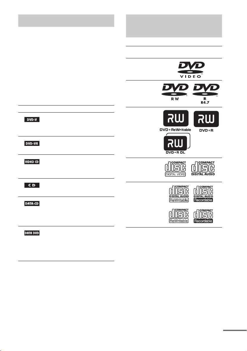
This System Can Play the
• The instructions in this manual describe the
controls on the remote. You can also use the
controls on the control unit if they have the
same or similar names as those on the remote.
• The Control Menu items may be different
depending on the area.
• “DVD” may be used as a general term for
DVD VIDEOs, DVD+RWs/DVD+Rs, and
DVD-RWs/DVD-Rs.
• The following symbols are used in this
manual.
Symbol Meaning
Functions available for DVD
VIDEOs, DVD-Rs/DVD-RWs in
video mode, and DVD+Rs/
DVD+RWs
Functions available for DVD-Rs/
DVD-RWs in VR (Video
Recording) mode
Functions available for VIDEO
CDs (including Super VCDs or CDRs/CD-RWs in video CD format or
Super VCD format)
Functions available for music CDs
or CD-Rs/CD-RWs in music CD
format
Functions available for DATA CDs
(CD-ROMs/CD-Rs/CD-RWs)
containing MP3
JPEG image files, and DivX
video files
Functions available for DATA
DVDs (DVD-ROMs/DVD-Rs/
DVD-RWs/DVD+Rs/DVD+RWs)
containing MP3
JPEG image files, and DivX
video files
1)
audio tracks,
1)
audio tracks,
2)3)
2)3)
Following Discs
Format of
discs
DVD VIDEO
DVD-RW/
DVD-R
DVD+RW/
DVD+R
VIDEO CD
(Ver. 1.1 and
2.0 discs)/
Audio CD
CD-RW/CD-R
(audio data)
(MP3 files)
(JPEG files)
“DVD+RW,” “DVD-RW,” “DVD+R,”
“DVD VIDEO,” and the “CD” logos are trademarks.
Disc logo
1)
MP3 (MPEG1 Audio Layer 3) is a standard format
defined by ISO/MPEG which compresses audio data.
2)
DivX® is a video file compression technology,
developed by DivX, Inc.
3)
DivX, DivX Certified, and associated logos are
trademarks of DivX, Inc. and are used under license.
continue
GB
5
Page 6

Note about CDs/DVDs
The system can play CD-ROMs/CD-Rs/CDRWs recorded in the following formats:
– audio CD format
– video CD format
– MP3 audio tracks, JPEG image files, and
DivX video files of format conforming to ISO
9660 Level 1/Level 2, or its extended format,
Joliet
The system can play DVD-ROMs/DVD+RWs/
DVD-RWs/DVD+Rs/DVD-Rs recorded in the
following formats:
– MP3 audio tracks, JPEG image files, and
DivX video files of format conforming to
UDF (Universal Disk Format)
Example of discs that the system cannot play
The system cannot play the following discs:
• CD-ROMs/CD-Rs/CD-RWs other than those
recorded in the formats listed on page 5
• CD-ROMs recorded in PHOTO CD format
• Data part of CD-Extras
• DVD Audios
• DATA DVDs that do not contain MP3 audio
tracks, JPEG image files, or DivX video files
•DVD-RAMs
• A DVD VIDEO with a different region code
(page 7, 107).
• Super Audio CD
• A disc that has a non-standard shape (e.g., card
shaped, heart shaped).
• A disc that has a commercially available
accessory attached, such as a label or ring.
Ring
Label
• An adapter to convert an 8 cm disc to standard
size.
Adapter
• A disc with paper or stickers on it.
• A disc that has the adhesive of cellophane tape
or a sticker still left on it.
Notes about CD-R/CD-RW/DVD-R/
DVD-RW/DVD+R/DVD+RW
In some cases, CD-R/CD-RW/DVD-R/DVDRW/DVD+R/DVD+RW cannot be played on
this system due to the recording quality or
physical condition of the disc, or the
characteristics of the recording device and
authoring software.
The disc will not play if it has not been correctly
finalized. For more information, see the
operating instructions for the recording device.
Note that some playback functions may not
work with some DVD+RWs/DVD+Rs, even if
they have been correctly finalized. In this case,
view the disc by normal playback. Also some
DATA CDs/DATA DVDs created in Packet
Write format cannot be played.
Music discs encoded with
copyright protection
technologies
This product is designed to play back discs that
conform to the Compact Disc (CD) standard.
Recently, various music discs encoded with
copyright protection technologies are marketed
by some record companies. Please be aware that
among those discs, there are some that do not
conform to the CD standard and may not be
playable by this product.
GB
6
Page 7

Note on DualDiscs
A DualDisc is a two sided disc product which
mates DVD recorded material on one side with
digital audio material on the other side.
However, since the audio material side does not
conform to the Compact Disc (CD) standard,
playback on this product is not guaranteed.
About Multi Session CD
• This system can play Multi Session CDs when
an MP3 audio track is contained in the first
session. Any subsequent MP3 audio tracks
recorded in later sessions can also be played
back.
• This system can play Multi Session CDs when
a JPEG image file is contained in the first
session. Any subsequent JPEG image files
recorded in later sessions can also be played
back.
• If audio tracks and images in music CD format
or video CD format are recorded in the first
session, only the first session will be played
back.
Region code
operating instructions supplied with the DVDs
or VIDEO CDs.
Copyrights
This product incorporates copyright protection
technology that is protected by U.S. patents and
other intellectual property rights. Use of this
copyright protection technology must be
authorized by Macrovision, and is intended for
home and other limited viewing uses only unless
otherwise authorized by Macrovision. Reverse
engineering or disassembly is prohibited.
This system incorporates with Dolby* Digital
and Dolby Pro Logic (II) adaptive matrix
surround decoder and the DTS** Digital
Surround System.
* Manufactured under license from Dolby
Laboratories.
“Dolby,” “Pro Logic,” and the double-D symbol are
trademarks of Dolby Laboratories.
** Manufactured under license from DTS, Inc. “DTS”
and “DTS Digital Surround” are registered
trademarks of DTS, Inc.
Your system has a region code printed on the
bottom of the control unit and will only play
DVDs labeled with the same region code.
DVD VIDEOs labeled will also play on this
ALL
system.
If you try to play any other DVD VIDEO, the
message [Playback prohibited by area
limitations.] will appear on the TV screen.
Depending on the DVD VIDEO, no region code
indication may be given even though playing the
DVD VIDEO is prohibited by area restrictions.
Note on playback operations of DVDs and VIDEO CDs
Some playback operations of DVDs and VIDEO
CDs may be intentionally set by software
producers. Since this system plays DVDs and
VIDEO CDs according to the disc contents the
software producers designed, some playback
features may not be available. Be sure to read the
GB
7
Page 8
Getting Started – BASIC –
Unpacking
• Control unit (1)
• Speakers (5)
• Subwoofer (1)
• AM loop antenna (aerial) (1)
• FM wire antenna (aerial) (1)
•Video Cord (1)
• Remote Commander (remote) (1)
• R6 (size AA) batteries (2)
Getting Started – BASIC –
• Calibration mic (1)
• Brackets (5)
• Wrench (1)
• Operating Instructions
• Quick Start Guide (card) (1)
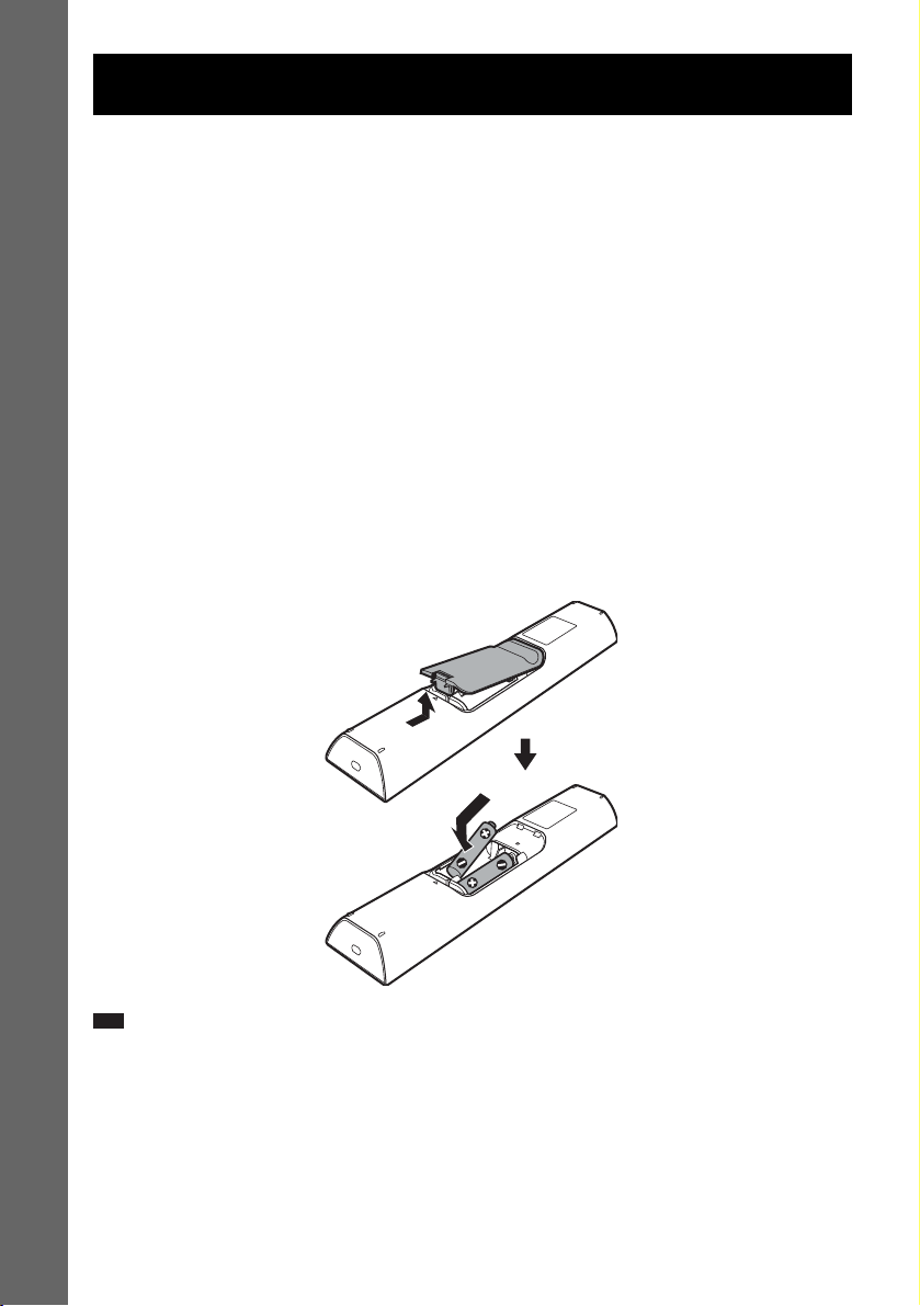
Inserting batteries into the remote
You can control the system using the supplied remote. Insert two R6 (size AA) batteries by matching
the 3 and # ends on the batteries to the markings inside the compartment. To use the remote, point it
at the remote sensor on the control unit.
Note
• Do not leave the remote in an extremely hot or humid place.
• Do not use a new battery with an old one.
• Do not drop any foreign object into the remote casing, particularly when replacing the batteries.
• Do not expose the remote sensor to direct sunlight or lighting apparatus. Doing so may cause a malfunction.
• If you do not intend to use the remote for an extended period of time, remove the batteries to avoid possible damage
from battery leakage and corrosion.
GB
8
Page 9
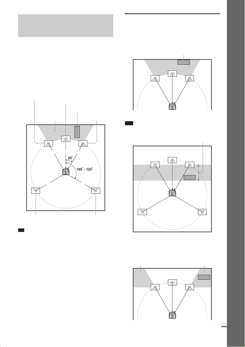
p
Step 1: Positioning the
)
d
Speakers
For the best possible surround sound, all the
speakers other than the subwoofer should be
placed at the same distance from the listening
position (1). It is recommended that the
subwoofer should be placed (2).
Place speakers and subwoofer as illustrated
below.
Front speaker (L)
Center speaker
Subwoofer
2
1 1 1
Front speaker (R)
11
Using the subwoofer efficiently
To reinforce the bass sound, place the subwoofer
possible close to a wall.
Close to a wall
Note
• If the subwoofer is to be placed ahead of the front
speaker, the distance should be less than 0.5 m.*
*
Getting Started – BASIC –
Surround speaker (L) Surround speaker (R
Ti
• You can also place the subwoofer either side, facing
the listening position.
• When you install the speaker, the speaker face may be
unstable. In this case, use a commercially available
wire clamper or a commercially available tape, etc.,
to secure the speaker cord.
• You may not get the bass sound efficiently when the
subwoofer is placed outside (3). You need to adjust
the setting of the distance from the listening position.
33
continue
GB
9
Page 10
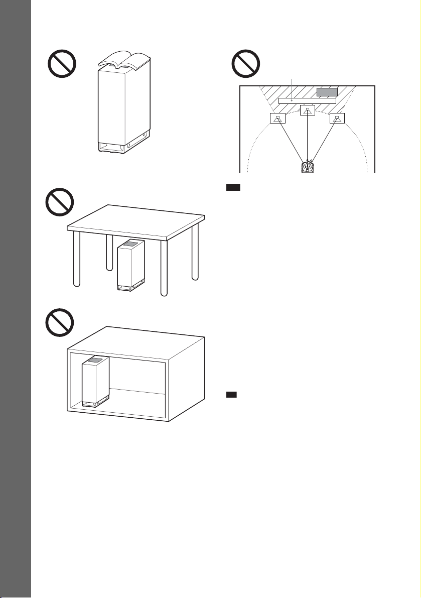
• Do not place objects on the top of the subwoofer
p
where the speaker unit is installed.
Getting Started – BASIC –
• Do not place the subwoofer under a desk or in a
cabinet, etc.
• Do not place the subwoofer back of the obstruction,
such as TV, etc. Middle range sound will fall.
TV etc.
Note
• Do not set the speakers in an inclined position.
• Do not place the speakers in locations that are:
– Extremely hot or cold
– Dusty or dirty
– Very humid
– Subject to vibrations
– Subject to direct sunlight
• Use caution when placing the speakers and/or
speaker stands (not supplied) that are attached with
the speakers on a specially treated (waxed, oiled,
polished, etc.) floor, as staining or discoloration may
result.
• When cleaning, use a soft cloth such as a cleaning
cloth for glasses.
• Do not use any type of abrasive pad, scouring
powder, or solvent such as alcohol or benzine.
• Image distortion on the TV screen may occur
depending on the location of the subwoofer. In this
case, place the subwoofer away from the TV.
Ti
• When you change the positions of the speakers, it is
recommended that you change the settings. For
details, see “Calibrating the Appropriate Settings
Automatically” (page 85).
GB
10
Page 11
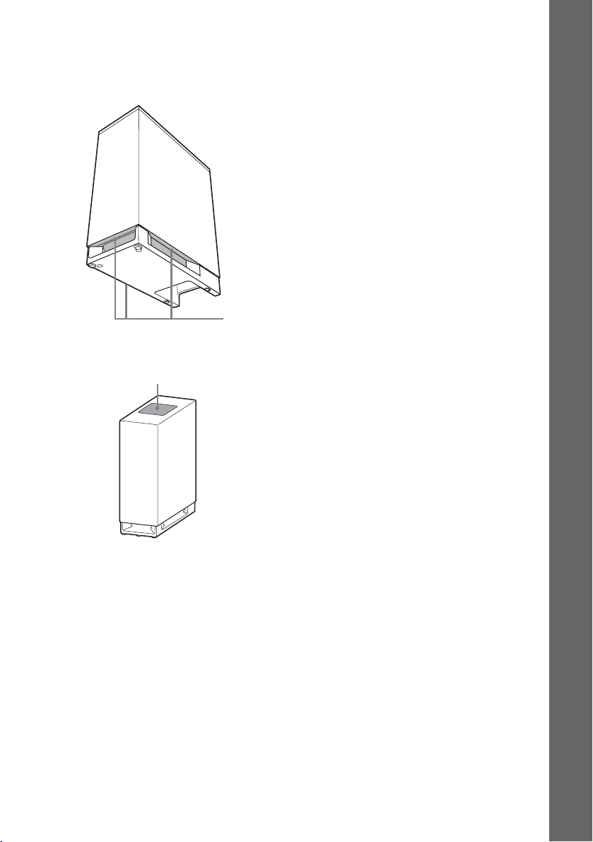
Note on handling the subwoofer
• Do not place your hand into the slit of the subwoofer
when lifting it. The speaker driver may be damaged.
When lifting, hold the bottom of the subwoofer.
Subwoofer
Slits
• Do not push the top of the subwoofer where the
speaker unit is installed.
Speaker unit
Getting Started – BASIC –
11
GB
Page 12
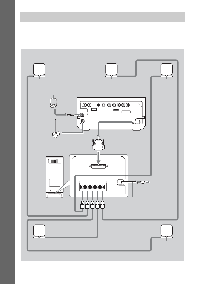
Step 2: Connecting the System
The following is the basic connection of the system.
Refer to the connection diagram below, and read the additional information from 1 to 4 on the
following pages.
Getting Started – BASIC –
2 Front
speaker (L)
3 AM loop antenna (aerial)
3 FM wire
antenna
(aerial)
Bottom of the
subwoofer
2 Center speaker
Rear of the control unit
DMPORT
1 Plug
2 Front
speaker (R)
12
GB
2 Surround
speaker (L)
Subwoofer
SPEAKER
SYSTEM CONTROL
ONLY FOR SS-IS10
ONLY FOR HCD-IS10
CENTERSUR LSUR RFRONT LFRONT R
4 AC power cord
(mains lead)
2 Surround
speaker (R)
Page 13
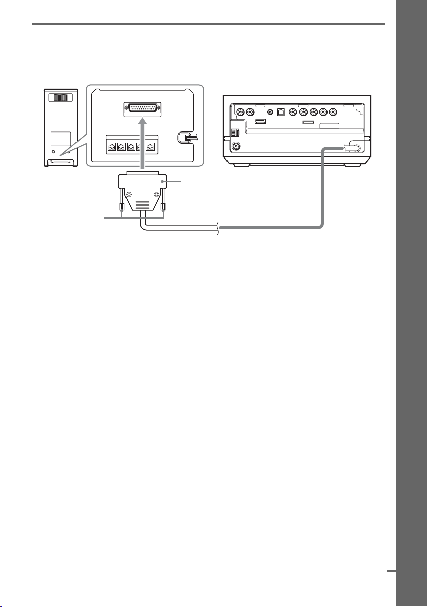
1 Connecting the Control unit
d
Connect the system connector of the control unit to the SYSTEM CONTROL jack of the subwoofer.
Insert the plug of the SYSTEM CONTROL cord, then secure the screws of the plug.
Bottom of the subwoofer
Rear of the control unit
SYSTEM CONTROL
ONLY FOR HCD-IS10
DMPORT
SPEAKER
ONLY FOR SS-IS10
CENTERSUR LSUR RFRONT LFRONT R
Getting Started – BASIC –
Subwoofer
Screws
Plug
SYSTEM CONTROL cord
continue
GB
13
Page 14
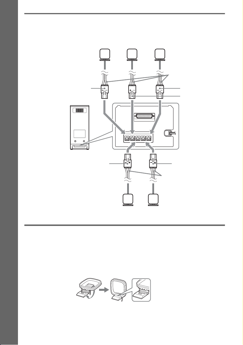
2 Connecting the Speakers
Connect the connectors of the speaker cords to their corresponding SPEAKER jacks. The connectors
of the speaker cords are the same color as the jacks to be connected.
Center speakerFront speaker (R) Front speaker (L)
Speaker cords
Getting Started – BASIC –
Red
Subwoofer
Gray
SPEAKER
SYSTEM CONTROL
ONLY FOR SS-IS10
ONLY FOR HCD-IS10
CENTERSUR LSUR RFRONT LFRONT R
Speaker cords
Surround speaker (L)Surround speaker (R)
Green
White
Bottom of the
subwoofer
Blue
3 Connecting the Antenna (Aerial)
To connect the AM loop antenna (aerial)
The shape and the length of the antenna (aerial) is designed to receive AM signals. Do not dismantle
or roll up the antenna (aerial).
1 Remove only the loop part from the plastic stand.
2 Set up the AM loop antenna (aerial).
14
GB
Page 15
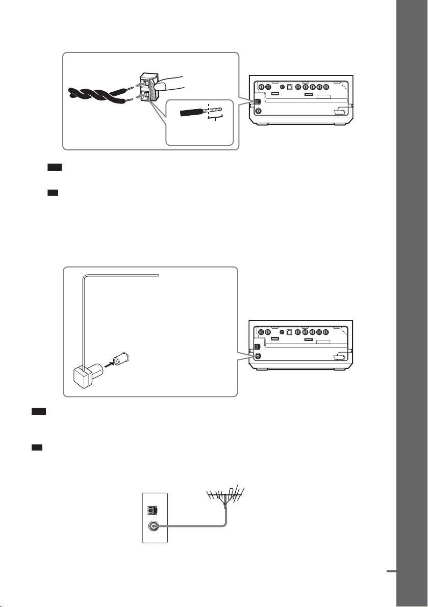
3 Connect the cords to the AM antenna (aerial) terminals.
p
p
d
The cords can be connected to either terminal.
Insert the cords pushing down the terminal clamp.
DMPORT
Insert until this
part.
Note
• Do not place the AM loop antenna (aerial) near the system or other AV equipment, as noise may result.
Ti
• Adjust the direction of the AM loop antenna (aerial) for best AM broadcast sound.
4 Make sure the AM loop antenna (aerial) is connected firmly by pulling softly.
To connect the FM wire antenna (aerial)
Connect the FM wire antenna (aerial) to the FM 75 Ω COAXIAL jack.
FM wire antenna (aerial)
(supplied)
Getting Started – BASIC –
DMPORT
FM 75 Ω COAXIAL jack
Note
• Be sure to fully extend the FM wire antenna (aerial).
• After connecting the FM wire antenna (aerial), keep it as horizontal as possible.
Ti
• If you have poor FM reception, use a 75-ohm coaxial cable (not supplied) to connect the control unit to an outdoor
FM antenna (aerial) as shown below.
Rear of the control unit
Outdoor FM antenna (aerial)
continue
15
GB
Page 16
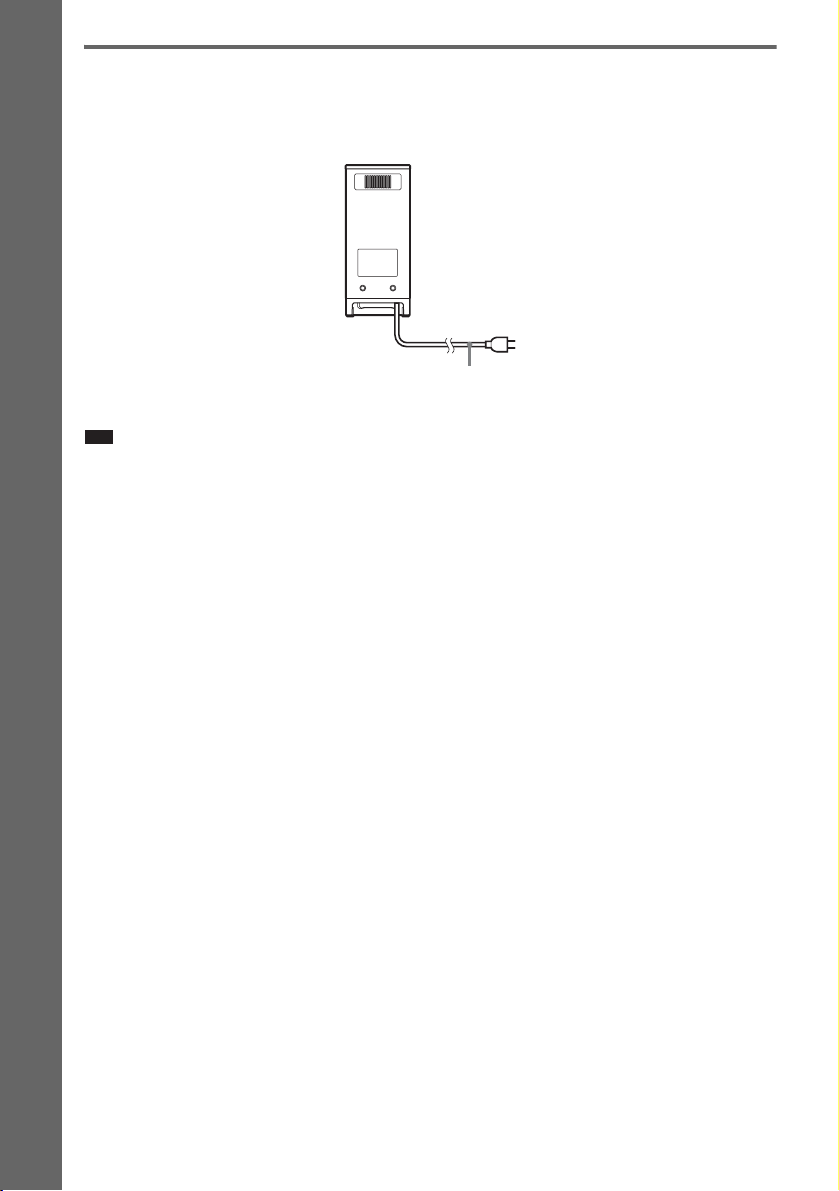
4 Connecting the AC power cord (mains lead)
Before connecting the AC power cord (mains lead) of the subwoofer to a wall outlet (mains), connect
all the speakers to the subwoofer (page 14).
Subwoofer
Getting Started – BASIC –
AC power cord
(mains lead)
Note
• After connecting the AC power cord (mains lead), wait about 20 seconds before turning on the power by pressing
"/1.
To a wall outlet
(mains)
16
GB
Page 17
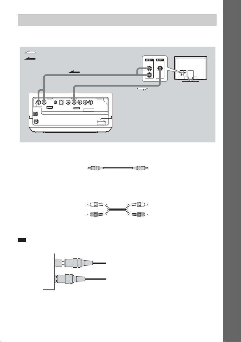
Step 3: Connecting the TV
The following is the basic connection of the control unit and TV. For other TV connections, see
page 21. For other component connections, see page 24.
Getting Started – BASIC –
: Video signal flow
: Audio signal flow
B
VIDEO
AUDIO
IN
OUT
L
R
TV
A
DMPORT
Rear of the control unit
Required cords
A Video cord
.
This connection sends the image to the TV. Connect the VIDEO OUT (VIDEO) jack of the control unit
to the VIDEO IN jack of the TV.
B Audio cord (not supplied)
Yellow
White (L/audio)
Red (R/audio)
This connection sends TV sound to the system. You can enjoy TV sound from the speakers with this
connection. Connect the TV (AUDIO IN) jacks of the control unit to the AUDIO OUT jacks of the TV.
Note
• When connecting the jack, insert the plug into the jack as far as it will go.
Example
Incorrect
Correct
17
GB
Page 18
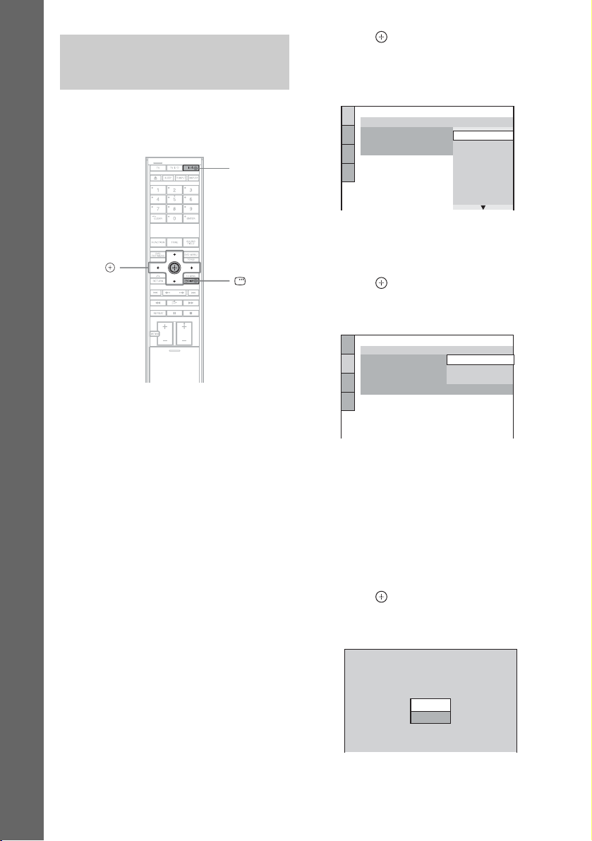
Step 4: Performing the Quick Setup
4 Press without inserting a disc.
The Setup Display for selecting the
language used in the on-screen display
appears on the TV screen.
Follow the steps below to make the minimum
number of basic adjustments for using the
system.
Getting Started – BASIC –
C/X/x/c,
1 Turn on the TV.
2 Press [/1.
The system turns on.
3 Switch the input selector on your TV so
that the signal from the system
appears on the TV screen.
[Press [ENTER] to run QUICK SETUP.]
appears at the bottom of the TV screen. If
this message does not appear, recall the
Quick Setup display (page 20) and perform
again.
"/1
DISPLAY
LANGUAGE SETUP
OSD:
MENU:
AUDIO:
SUBTITLE:
ENGLISH
ENGLISH
FRAN
ÇAIS
DEUTSCH
ITALIANO
ESPAÑOL
NEDERLANDS
DANSK
SVENSKA
5 Press X/x to select a language.
The system displays the menu and subtitles
in the selected language.
6 Press .
The Setup Display for selecting the aspect
ratio of the TV to be connected appears.
SCREEN SETUP
TV TYPE:
YCBCR/RGB (HDMI):
SCREEN SAVER:
BACKGROUND:
4:3 OUTPUT:
4:3 LETTER BOX
16:9
16:9
4:3 PAN SCAN
FULL
7 Press X/x to select the setting that
matches your TV type.
x If you have a wide-screen TV or a 4:3
standard TV with a wide-screen mode
[16:9] (page 90)
x If you have a 4:3 standard TV
[4:3 LETTER BOX] or [4:3 PAN SCAN]
(page 90)
8 Press .
The [AUTO CALIBRATION] display
appears.
18
AUTO CALIBRATION
Connect calibration mic. Start
measurement?
YES
NO
GB
Page 19
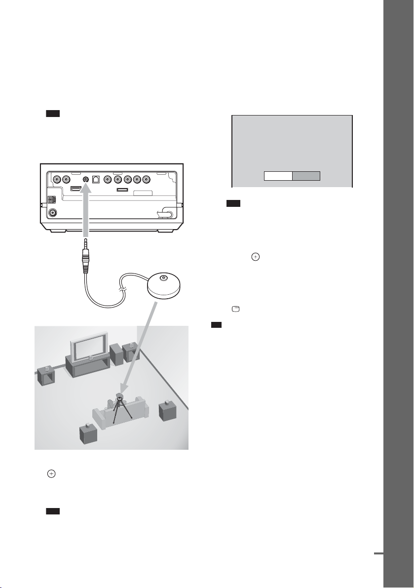
9 Connect the calibration mic to the
p
d
ECM-AC2 jack on the rear of the control
unit, and set it up at the ear level using
a tripod, etc. (not supplied).
The front of each speaker should face the
calibration mic, and there should be no
obstruction between the speakers and the
calibration mic.
Note
• The ECM-AC2 jack is used for the supplied
calibration mic only. Do not connect other
microphones.
Rear of the control unit
DMPORT
To E C M- AC 2 j ac k
Calibration mic
volume down. Give consideration to children
and neighbor.
• Avoid being in the measurement area and
making noise during the measurement (which
takes about 1 minute), as it may interfere with
measurement.
11Unplug the calibration mic and press C/
c to select [YES].
Measurement complete.
FRONT L :
FRONT R :
CENTER :
SUBWOOFER :
SURROUND L :
SURROUND R :
If OK, unplug calibration mic and select
“YES”.
Note
• The environment of the room in which the
system is installed may affect measurements.
• If measurement fails, follow the message then
retry [AUTO CALIBRATION].
YES
5.00m 0.0dB
5.00m
0.0dB
5.00m + 1.0dB
5.00m + 4.0dB
3.00m
-
2.0dB
3.00m
-
2.0dB
NO
12Press .
Quick Setup is finished. All connections
and setup operations are complete.
To quit the Quick Setup
Press DISPLAY in any Step.
Ti
• If you cancel [AUTO CALIBRATION], perform the
speaker settings in “Settings for the Speakers”
(page 94).
• If you change the position of the speakers, reset the
speaker settings. See “Calibrating the Appropriate
Settings Automatically” (page 85).
• If you want to change any of the settings, see “Using
the Setup Display” (page 88).
• For details on [AUTO CALIBRA TION] and the error
messages of [AUTO CALIBRATION], see
“Calibrating the Appropri ate Settings Automatically”
(page 85).
Getting Started – BASIC –
10 Press X/x to select [YES], then press
.
[AUTO CALIBRATION] starts. Be quiet
during the measurement.
Note
• Loud test sound is output when [AUTO
CALIBRATION] starts. You cannot turn the
continue
GB
19
Page 20
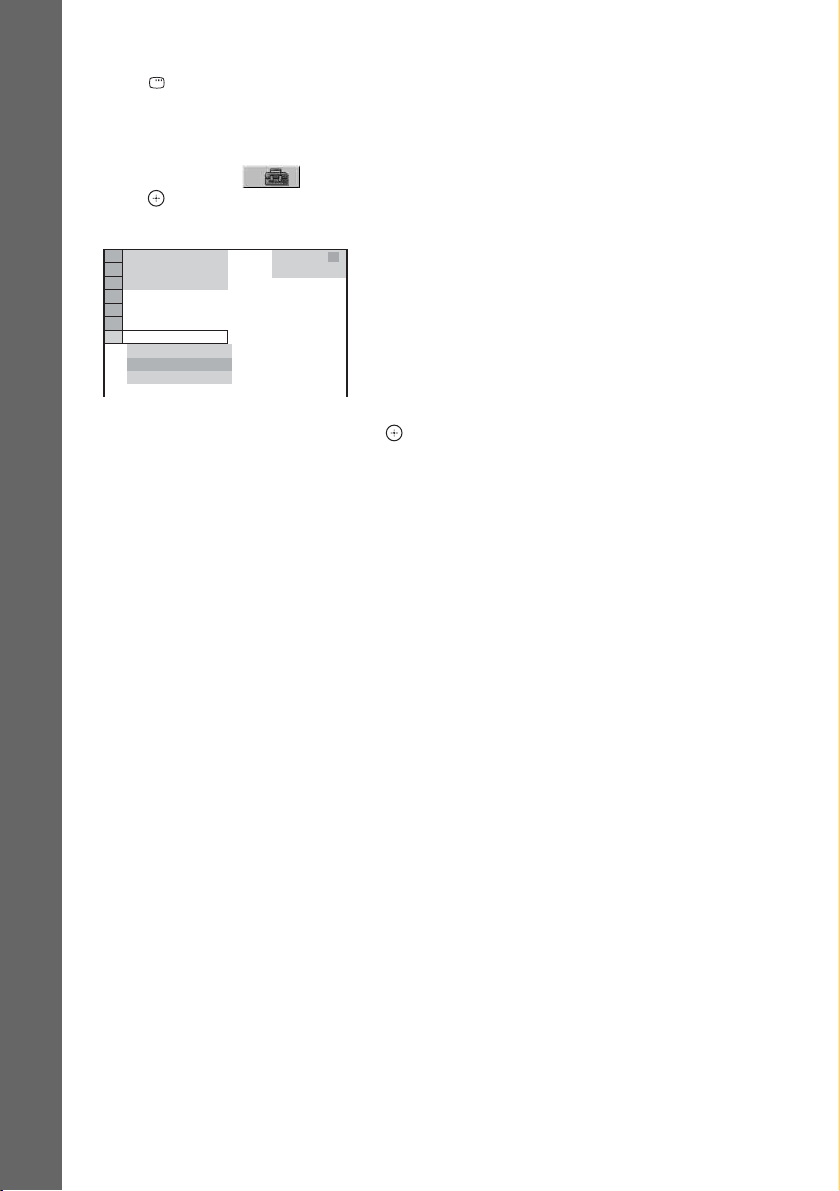
To recall the Quick Setup display
1 Press DISPLAY when the system is in
stop mode.
The Control Menu display appears on the TV
screen.
2 Press X/x to select [SETUP], then
press .
The options for [SETUP] appear.
)
1 2 ( 2 7
)
1 8 ( 3 4
T
0 : 0 0 : 0 2
DVD VIDEO
Getting Started – BASIC –
QUICK
QUICK
CUSTOM
RESET
BNR
3 Press X/x to select [QUICK], then press .
The Quick Setup display appears.
20
GB
Page 21
Getting Started – ADVANCED –
d
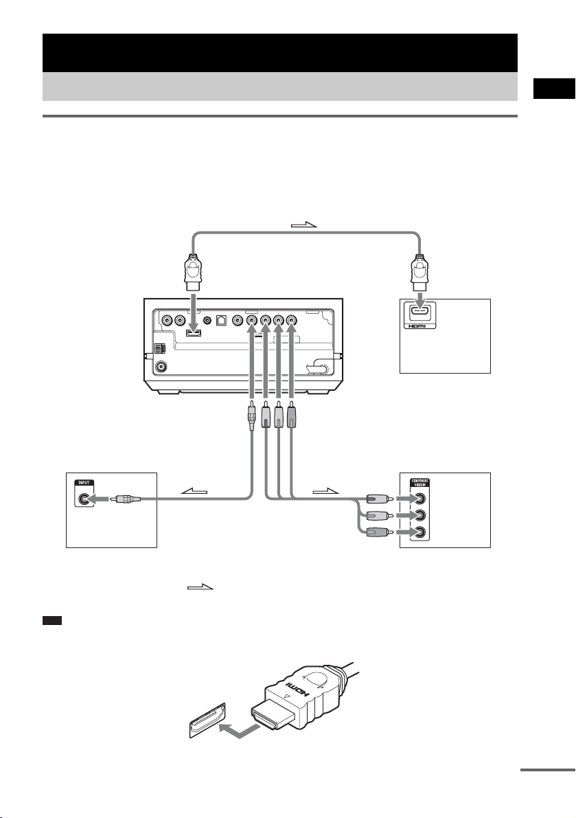
Connecting the TV (Advanced)
Connecting the TV with the video cord/component video cord/ HDMI cable
Sends the played back DVD image to the connected TV.
Check the jacks of your TV, and choose connection method A, B, or C. Picture quality improves in
order from A (standard) to C (HDMI).
Getting Started – ADVANCED –
To HDMI OUT jack
Rear of the
control unit
DMPORT
C
To VIDEO OUT
(VIDEO) jack
VIDEO
IN
To the video
input jack
TV with VIDEO IN jack
A
: Signal flow
Note
• When connecting the HDMI cable, make sure that the direction of jacks are the same.
.
To VIDEO OUT
(COMPONENT) jacks
To the component
video input jacks
B
To the HDMI input
jack
IN
TV with HDMI IN jack
Y
PB/CB
PR/CR
TV with COMPONENT
VIDEO IN jacks
continue
GB
21
Page 22
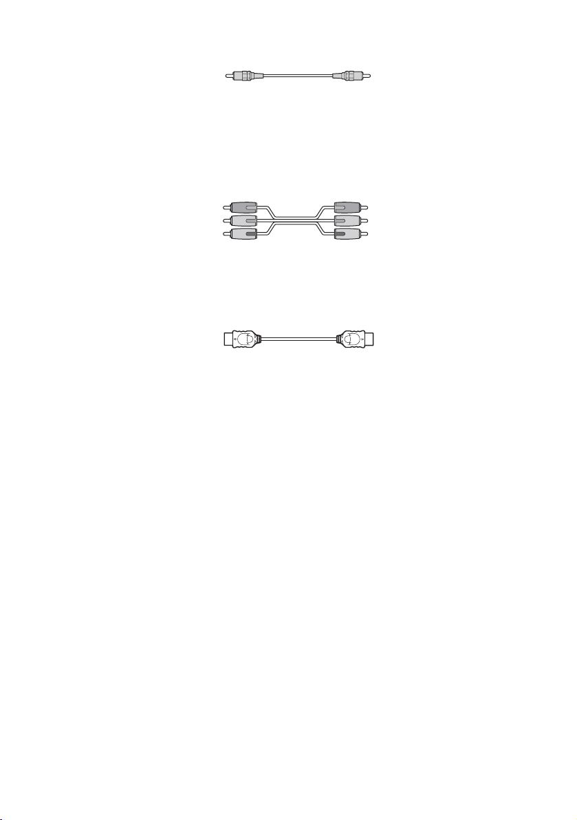
A To connect to a TV with the VIDEO IN jack
Connect the video cord.
.
Yellow
B To connect to a TV with the COMPONENT VIDEO IN jacks
Connect a component video cord (not supplied). To use the VIDEO OUT (COMPONENT) jacks (Y,
P
B/CB, PR/CR) instead of the video jacks, your TV monitor must be equipped with COMPONENT
VIDEO IN jacks (Y, P
B/CB, PR/CR). If your TV accepts progressive format signals, you can use this
connection and set the output channel of the system to progressive format (this system is compatible
with the 525 or 625 progressive format) (page 91).
Red
Blue
Green
C To connect to a TV with the HDMI (high-definition multimedia
interface)/DVI (digital visual interface) IN jack
Use a certified HDMI (high-definition multimedia interface) cable (not supplied) to enjoy high quality
digital picture and sound through the HDMI OUT (high-definition multimedia interface out) jack.
HDMI (high-definition multimedia interface)
The system incorporates High-Definition Multimedia Interface (HDMI
HDMI, the HDMI logo and High-Definition Multimedia Interface are trademarks or registered trademarks of HDMI
Licensing LLC.
To connect to a TV with DVI (digital visual interface) input
TM
) technology.
Use an HDMI (high-definition multimedia interface)-DVI (digital visual interface) converter cord (not
supplied) with an HDMI (high-definition multimedia interface)-DVI (digital visual interface) adaptor
(not supplied). The DVI (digital visual interface) jack will not accept any audio signals. Furthermore,
you cannot connect the HDMI OUT (high-definition multimedia interface out) jack to DVI (digital
visual interface) jacks that are not HDCP (high-bandwidth digital content protection) compliant (e.g.,
DVI (digital visual interface) jacks on PC displays).
22
GB
Page 23
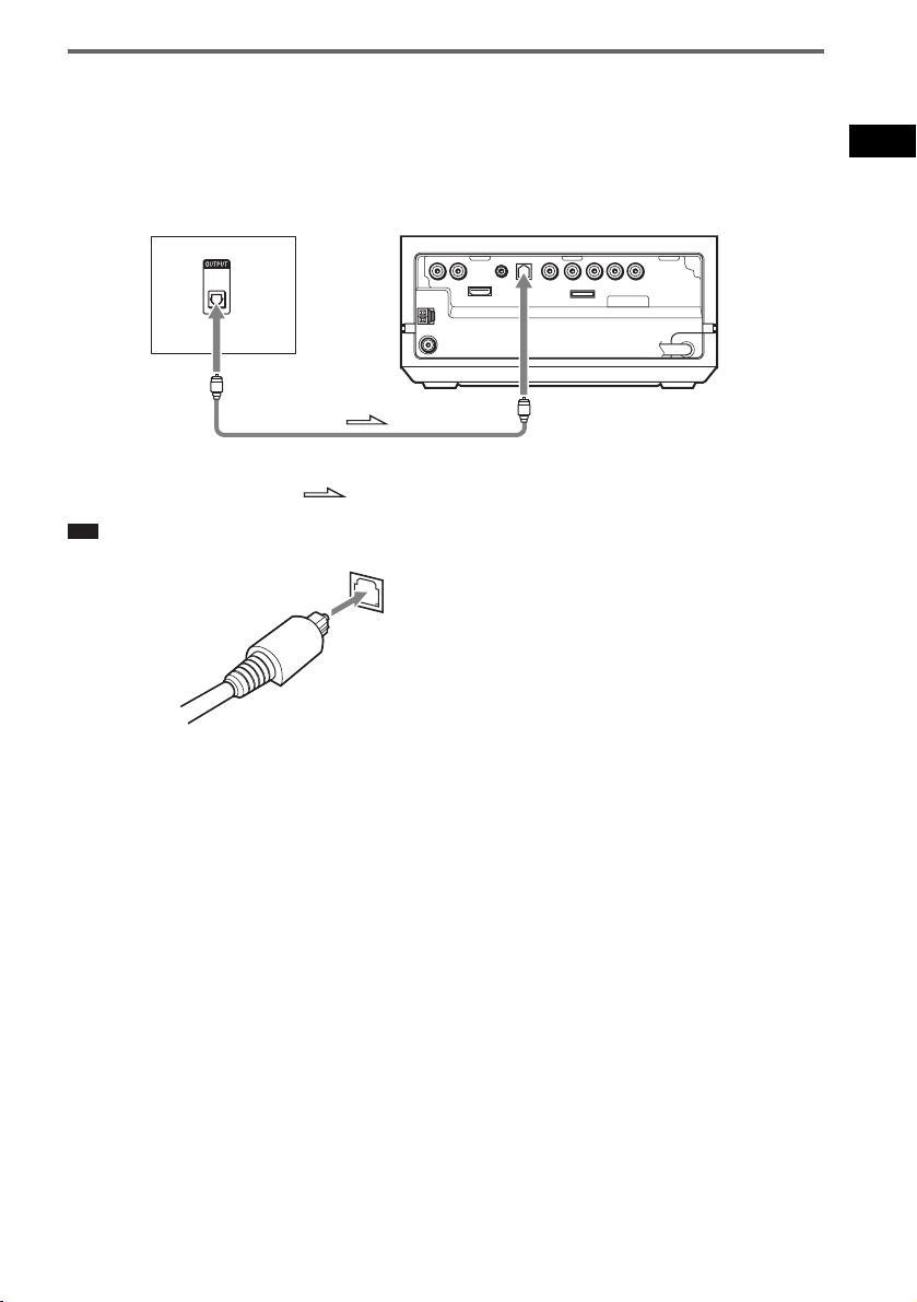
Connecting the TV with the digital optical cord
A TV with a digital optical out jack (TV with built-in digital satellite receiver, etc.) can be connected
to the TV (DIGITAL IN OPTICAL) jack instead of the TV (AUDIO IN) jacks on the rear of the control
unit.
The system can accept both the digital and analog signals. Digital signals have priority over analog
signals. If the digital signal ceases, the analog signal will be processed after a few seconds.
TV with the digital optical jack
OPTICAL
DIGITAL
OUT
To the digital
optical output jack
Note
• When connecting the digital optical cord, insert the connector until it clicks.
Rear of the control unit
DMPORT
To TV (DIGITAL
IN OPTICAL) jack
: Audio signal flow
Getting Started – ADVANCED –
23
GB
Page 24
p
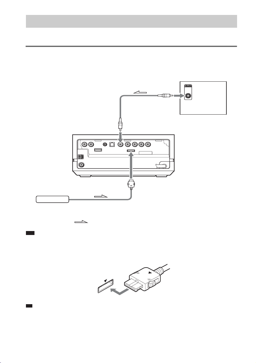
Connecting Other Components
You can enjoy other components.
Connecting the system and the other component
Outputs the other component through the speakers of this system.
VCR, digital satellite
To the digital
coaxial output jack
To SAT/CABLE
(DIGITAL IN COAXIAL) jack
Rear of the
control unit
DMPORT
To DMPORT jack
receiver, etc.
COAXIAL
DIGITAL
OUT
DIGITAL MEDIA
PORT adapter
: Signal flow
Note
• Do not connect or disconnect the DIGITAL MEDIA PORT adapter to/from the control unit while the system is
turned on.
• When connecting the DIGITAL MEDIA PORT adapter, be sure to match the V marks.
.
Ti
• You can assign a digital sound input corresponding with the function “TV” and “SAT/CABLE.” For details, see
[DIGITAL IN] (page 93).
GB
24
Page 25
To connect the DIGITAL MEDIA PORT adapter
Connect a DIGITAL MEDIA PORT adapter (not supplied) to the DMPORT jack. For details of the
DIGITAL MEDIA PORT adapter, see “Using the DIGITAL MEDIA PORT Adapter” (page 80).
If you connect a digital satellite receiver with a DIGITAL OUT (COAXIAL
or OPTICAL) jack
A digital satellite receiver can be connected to the SAT/CABLE (DIGITAL IN COAXIAL) or TV
(DIGITAL IN OPTICAL) jack.
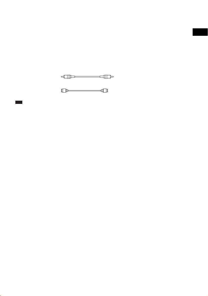
To connect, use a digital coaxial cord (not supplied) for the SAT/CABLE (DIGITAL IN COAXIAL)
jack or digital optical cord (not supplied) for the TV (DIGITAL IN OPTICAL) jack.
The system can accept both digital and analog signals. Digital signals have priority over analog signals.
If the digital signal ceases, the analog signal will be processed after a few seconds.
Digital coaxial cord
Digital optical cord
Note
• Be sure to make connections securely to avoid hum and noise.
Getting Started – ADVANCED –
25
GB
Page 26
p
34
Installing the Speakers on a Wall
You can use the speakers installed on a wall.
Installing the speakers on a wall
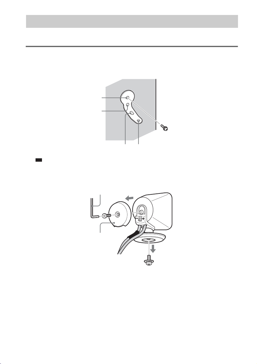
1 Prepare screws (not supplied) that are suitable for the holes of the bracket.
2 Secure the bracket to the wall using hole 1.
1
2
Ti
• To prevent the speaker from rotating, use the hole 2, too.
3 Remove the rear cap using the wrench (supplied), and remove the speaker pedestal
using a screwdriver (+) (not supplied).
Wrench (supplied)
Rear cap
GB
26
Page 27
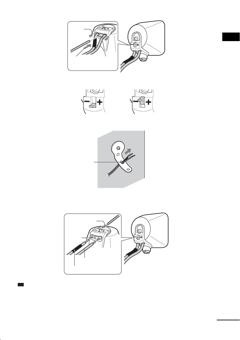
4 Push A with the supplied wrench (1), and then remove the speaker cords (2).
p
d
(2)
Getting Started – ADVANCED –
(1)
When the lever is down, the
speaker cords are locked.
A
When the lever is up, the
speaker cords can be removed.
5 Thread the speaker cords through hole 3.
3
6 Reconnect the detached speaker cords, matching 3/# to the appropriate speaker
terminals (1), and then push the lever down completely (2).
(2)
(1)
3
#
Ti
• If it is difficult to push the lever down, use the wrench (supplied).
continue
27
GB
Page 28
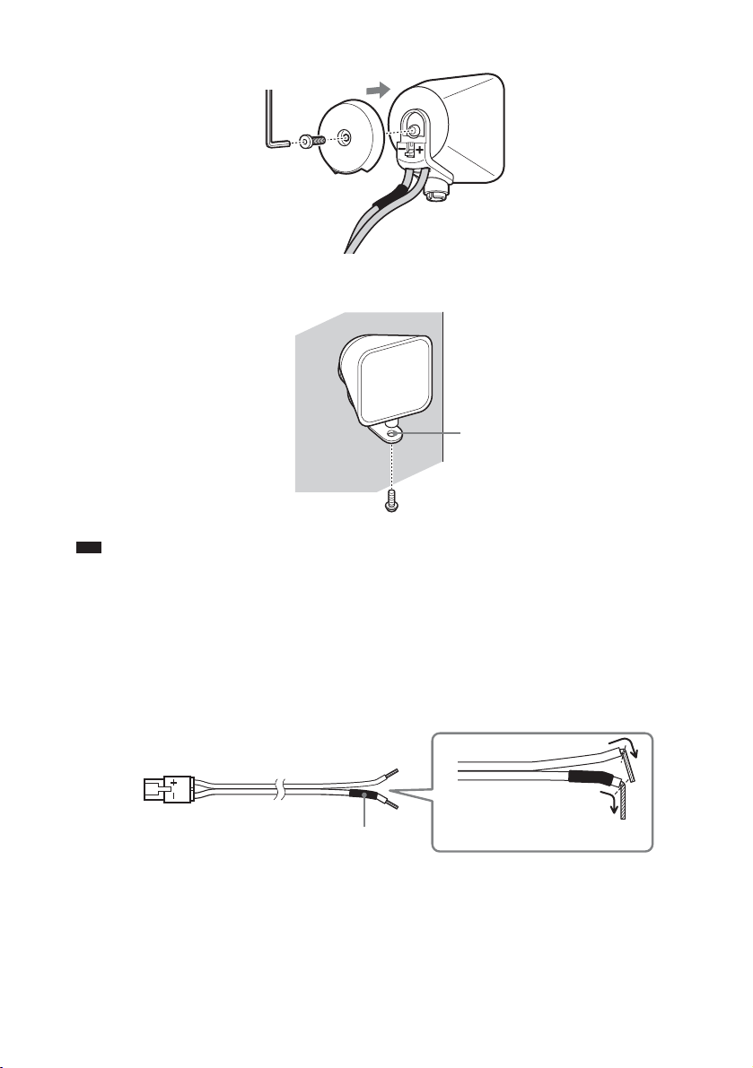
7 Reattach the rear cap using the wrench (supplied).
8 Secure the speaker to the bracket with the screw in Step 3 using hole 4.
4
Note
• Use screws that are suitable for the wall material and strength. As a plaster board wall is especially fragile, attach
the screws securely to a beam and fasten them to the wall. Install the speakers on a vertical and flat wall where
reinforcement is applied.
• Contact a screw shop or installer regarding the wall material or screws to be used.
• Sony is not responsible for accident or damage caused by improper installation, insufficient wall strength or
improper screw installation, natural calamity, etc.
About connecting speaker cord
The connectors of the speaker cords are the same color as the jacks to be connected.
28
3
#
Black
GB
Do not catch the
speaker cords
insulation in the speaker
terminals.
Page 29
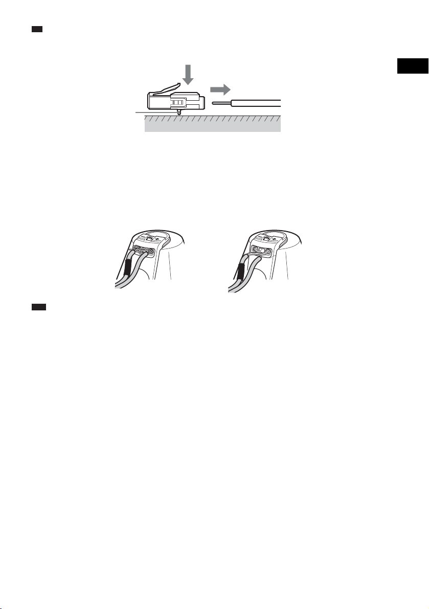
Ti
p
• You can remove the speaker cords from the connector. With the catch facing down, press and hold the connector
down against a flat surface (1) and remove the speaker cords from the connector (2).
(1)
(2)
Catch
To avoid short-circuiting the speakers
Short-circuiting of the speakers may damage the system. To prevent this, be sure to follow these
precautions when connecting the speakers. Make sure the bare wire of each speaker cord does not touch
another speaker terminal or the bare wire of another speaker cord, such as shown below.
Stripped speaker cord is
touching another speaker
terminal.
Note
• Be sure to match the speaker cords to the appropriate speaker terminals: 3 to +, and # to –. If the cords are
reversed, the sound will lack bass and may be distorted.
Stripped cords are touching each
other due to excessive removal of
insulation.
Getting Started – ADVANCED –
GB
29
Page 30
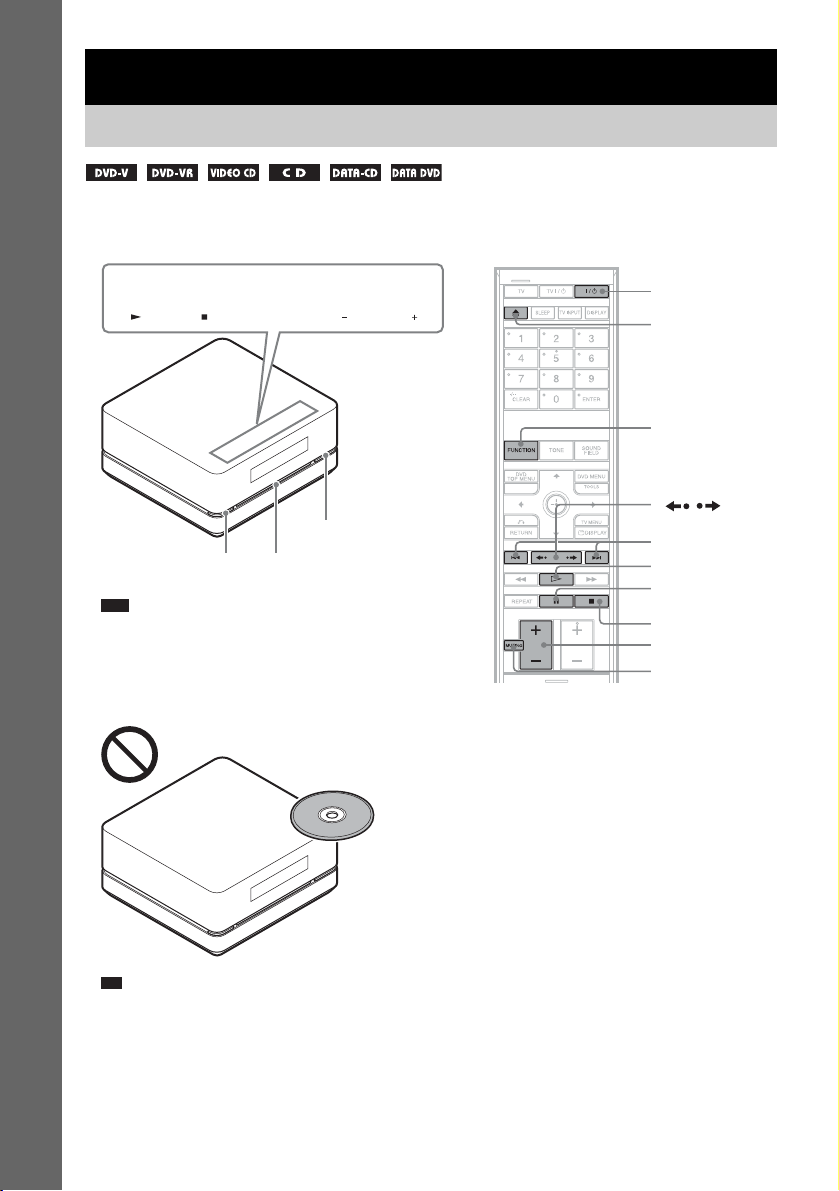
Basic Operations
p
Playing Discs
Depending on the DVD or VIDEO CD, some operations may be different or restricted.
Refer to the operation details supplied with your disc.
Soft-touch buttons
FUNCTION VOLUME
Basic Operations
Z
"/1
Disc slot
Note
• Soft-touch buttons function by touching lightly. Do not press
them strongly.
• Do not place objects on the top of the control unit. Doing so
may activate the soft-touch buttons or deactivate the buttons
of the control unit.
"/1
Z
FUNCTION
/
./>
H
X
x
VOLUME +/–
MUTING
Ti
• Soft-touch buttons function when they are lit up.
• You can select the way of displaying the soft-touch buttons
located on the top of the control unit (page 79).
GB
30
Page 31

1 Turn on your TV.
p
d
2 Switch the input selector on the TV to this system.
3 Press "/1.
The system turns on.
Unless the mode of the system is set to “DVD,” press FUNCTION on the remote or FUNCTION
(soft-touch button) on the control unit to select “DVD.”
“No Disc” appears in the front panel display and the system is ready for loading the disc.
4 Load a disc.
Push the disc into the disc slot until the disc is pulled in automatically.
Labeled side facing to upper surface
The disc is drawn into the control unit automatically and the following indication appears in the
front panel display.
Basic Operations
5 Press H on the remote, or touch N (soft-touch button) on the control unit.
The system starts playback (continuous play).
Adjust the VOLUME +/– on the remote or touch the VOLUME +/– (soft-touch button) on the
control unit.
Ti
• You can change the speed at which the volume is turned up and down.
To turn the volume up/down quickly:
– Press and hold the VOLUME +/– on the remote.
– Touch the VOLUME +/– (soft-t ouch button) on the control unit, when “VOLUME XX” ( X is a number) appears,
touch and hold the VOLUME +/–.
To set the volume up/down precisely:
– Press the VOLUME +/– briefly on the remote.
– Touch briefly VOLUME +/– (soft-touch button) on the control unit.
• When you connect the system and TV with the HDMI cable, you can operate them simply using the HDMI
CONTROL function. For details, see page 39.
Note
• When you set the HDMI CONTROL function to on, the TV that is connected to the control unit with the HDMI
cable can be synch-operated with the system. For details, see page 39.
continue
31
GB
Page 32

To save the power in standby mode
Press "/1 while the system turns on. To cancel standby mode, press "/1 once.
Note
• When the system is turned off, do not push a disc into the control unit.
Additional operations
To Press
Stop x
Pause X
Resume play after pause X / H on the remote or N (soft-touch button) on the
Go to the next chapter, track,
or scene
Basic Operations
Go back to the preceding
chapter, track, or scene
Turn off the sound
temporarily
Stop play and remove the
disc
Replay the previous scene* (instant replay) during playback.
Briefly fast forward the
current scene**
* DVD VIDEOs/DVD-RWs/DVD-Rs only. The button can be used except for DivX video files.
** DVD VIDEOs/DVD-RWs/DVD-Rs/DVD+RWs/DVD+Rs only. The button can be used except for DivX video
files.
Note
• You may not be able to use the instant replay or instant advance function with some scenes.
control unit.
> (except for JPEG)
. (except for JPEG)
MUTING. To cancel muting, press it again or VOLUME
+ to adjust the sound volume.
Z
(instant advance) during playback.
32
GB
Page 33

p
Enjoying the Radio or Other Components
d
Selecting the connected component
You can use a TV, VCR, or other components connected to the TV or SAT/CABLE jacks on the rear
of the control unit. Refer to the operating instructions supplied with the components for further
information.
FUNCTION
Basic Operations
Press FUNCTION repeatedly until the desired function name appears in the front panel
display.
Each time you press FUNCTION, the mode of the system changes in the following sequence.
DVD t FM t AM t TV t SAT/CABLE t DMPORT t DVD t …
Ti
• You can assign a digital sound input corresponding with the function “TV” and “SAT/CABLE.” For details, see
[DIGITAL IN] (page 93).
Note
• When you use both the TV (AUDIO IN) jacks (analog connection) and TV (DIGITAL IN OPTICAL) jack (digital
connection) at the same time, the digital connection takes priority.
continue
33
GB
Page 34

Changing the input level of the sound from connected components
Distortion may occur when listening to a component connected to the TV (AUDIO IN) jacks on the
rear of the control unit. This is not a malfunction and will depend on the component connected.
To prevent this, you can change the input level from the sound of the other components.
Basic Operations
With the cover opened.
FUNCTION
X/x/c,
SYSTEM
MENU
1 Press FUNCTION repeatedly until “TV” appears in the front panel display.
2 Press SYSTEM MENU.
3 Press X/x repeatedly until “ATTENUATE” appears in the front panel display, then press
or c.
4 Press X/x to select a setting.
The default setting is underlined.
• “ATT ON”
• “ATT OFF”: normal input level.
: attenuates the input level. The output level is changed.
5 Press .
The setting is made.
6 Press SYSTEM MENU.
The system menu turns off.
Note
• “ATTENUATE” appears only when the function is set to the “TV” function.
34
GB
Page 35

Enjoying TV or VCR Sound from All Speakers
You can enjoy TV or VCR sound from all the speakers in this system.
For details, see “Step 3: Connecting the TV” (page 17), “Connecting the TV (Advanced)” (page 21),
and “Connecting Other Components” (page 24).
FUNCTION
SOUND
FIELD
1 Press FUNCTION repeatedly until “TV” or “SAT/CABLE” appears in the front panel
display.
2 Press SOUND FIELD repeatedly until the sound field you want appears in the front panel
display.
When you want to output the TV sound or stereo sound of a 2 channel source from the all speakers,
select the “PLII MOVIE” or “PLII MUSIC” sound field.
For details of sound field, see page 37.
Note
• When you set the [HDMI CONTROL] setting in [CUSTOM SETUP] to [ON] (page 93), the System Audio Control
function is activated and no sound may be output from the TV. For details, see page 43.
• When you use both the TV (AUDIO IN) jacks (analog connection) and TV (DIGITAL IN OPTICAL) jack (digital
connection) at the same time, the digital connection takes priority.
Basic Operations
35
GB
Page 36

p
Selecting the Movie or Music Mode
You can choose a suitable sound mode for movies or music.
Basic Operations
MOVIE/
MUSIC
With the cover opened.
Press MOVIE/MUSIC during playback.
Press MOVIE/MUSIC repeatedly until the mode you want appears in the front panel display. The
default setting is underlined.
• “AUTO”
: selects the mode automatically to produce the sound effect depending on the disc or sound
stream.
• “MOVIE”: provides sound suitable for movies.
• “MUSIC”: provides sound suitable for music.
Ti
• When the movie or music mode is selected, “MOVIE” or “MUSIC” lights up in the front panel display. When
neither “MOVIE” or “MUSIC” lights up in the front panel display, “AUTO” is selected.
Note
• Depending on the disc or source, when you select “AUTO,” the beginning of the sound may be cut off as the
optimum mode is automatically selected. To avoid cutting the sound, select “MOVIE” or “MUSIC.”
GB
36
Page 37

Sound Adjustments
d
Enjoying Surround Sound by Using Sound Field
You can take advantage of surround sound
simply by selecting one of system’s preprogrammed sound fields. They bring the
exciting and powerful sound of movie theaters
into your home.
SOUND
FIELD
Automatic outputting of the original sound
x AUTO FORMAT DIRECT STANDARD
The auto decoding function automatically
detects the type of audio signal being input
(Dolby Digital, DTS, or standard 2 channel
stereo) and performs the proper decoding if
necessary. This mode presents the sound as it
was recorded/encoded, without adding any
effects (e.g. reverberation).
However, if there are no low frequency signals
(Dolby Digital LFE, etc.), it will generate a low
frequency signal for output to the subwoofer.
Outputting the sound from multiple speakers
x AUTO FORMAT DIRECT MULTI
This mode lets you enjoy audio playback of all
types of discs from multiple speakers.
Note
• The sound is not output from multiple speakers
depending on the source.
• Depending on the disc or source, the beginning of the
sound may be cut off as the optimum mode is
automatically selected. To avoid cutting the sound,
select “A.F.D. STD.”
Sound Adjustments
Press SOUND FIELD.
Press SOUND FIELD repeatedly until the sound
field you want appears in the front panel display.
All sound field
Sound field Display
AUTO FORMAT DIRECT
STANDARD
AUTO FORMAT DIRECT
MULTI
Dolby Pro Logic II MOVIE PLII MOVIE
Dolby Pro Logic II MUSIC PLII MUSIC
PORTABLE AUDIO
ENHANCER
OMNI-DIRECTIONAL
SOUND
A.F.D. STD
A.F.D. MULTI
P. AUDIO
OMNI-DIR
Outputting 2 channel sources like CDs by 5.1channel
x Dolby Pro Logic II MOVIE/MUSIC
Dolby Pro Logic II produces five full-bandwidth
output channels from 2 channel sources. This is
done using an advanced, high-purity matrix
surround decoder that extracts the spatial
properties of the original recording without
adding any new sounds or tonal colorations.
Note
• When the input signal is multi channel source, Dolby
Pro Logic II MOVIE/MUSIC are canceled and the
multi channel source is output directly.
• When the bilingual broadcast sound is input, Dolby
Pro Logic II MOVIE/MUSIC are not effective.
continue
37
GB
Page 38

Enjoying the sound effect
p
x PORTABLE AUDIO ENHANCER
This mode reproduces a clear enhanced sound
image from your portable audio device. This
mode is ideal for MP3 and other compressed
music.
x OMNI-DIRECTIONAL SOUND
This mode reproduces the stereo effect
everywhere surrounding by five satellite
speakers.
To turn the surround effect off
Press SOUND FIELD repeatedly until “A.F.D.
STD” appears in the front panel display.
Ti
• The system memorizes the last sound field selected
for each function mode.
Whenever you select a function such as DVD or
TUNER, the sound field that was last applied to
function is automatically applied again. For example,
if you listen to DVD with Dolby Pro Logic II MOVIE
as the sound field, then change to another function,
and then return to DVD, Dolby Pro Logic II MOVIE
will be applied again.
Adjusting the Bass, Middle, and Treble Level
You can adjust the bass, middle, and treble level
easily.
TONE
X/x,
1 Press TONE repeatedly until “BASS,”
“MIDDLE,” or “TREBLE” appears in the
front panel display.
• “BASS”: adjusts the bass level
(–6.0 – +6.0 dB, 0.5 dB increments).
• “MIDDLE”: adjusts the middle level
(–6.0 – +6.0 dB, 0.5 dB increments).
• “TREBLE”: adjusts the treble level
(–6.0 – +6.0 dB, 0.5 dB increments).
2 Press X/x to adjust.
The adjusted value appears in the front
panel display.
3 Press .
GB
38
Page 39

Using the HDMI CONTROL Function for ‘BRAVIA’ Theatre Sync
‘BRAVIA’ Theatre Sync can be used only with Sony ‘BRAVIA’ TVs that carry this function.
By connecting Sony components that are compatible with the HDMI CONTROL function with an
HDMI cable (not supplied), operation is simplified as below:
• One-Touch Play (page 42): By pressing only H on the remote, the TV turns on and is set for DVD
input mode automatically, and the sound is output automatically from the speakers of this system.
• System Audio Control (page 43): While watching TV, you can select to output the sound from the
TV speaker or the speakers of this system.
• System Power Off (page 44): When you turn the TV off by using the power button on the TV's
remote, the system turns off simultaneously.
HDMI CONTROL is a mutual control function standard used by HDMI CEC (Consumer Electronics
Control) for HDMI (high-definition multimedia interface).
The HDMI CONTROL function will not operate in the following cases:
• When you connect this system to a component which is not correspond with Sony's HDMI
CONTROL function.
• When you connect the control unit and components using other than the HDMI connection.
We recommend that you connect this system to products featuring ‘BRAVIA’ Theatre Sync.
Note
• Depending on the connected component, the HDMI CONTROL function may not work. See the operating
instructions of the component.
Using the HDMI CONTROL Function for ‘BRAVIA’ Theatre Sync
39
GB
Page 40

Preparing for the HDMI CONTROL function
To use the HDMI CONTROL function, set up the system and the TV.
Before you use the HDMI CONTROL function, be sure you have performed the following procedures.
1 Make sure that the control unit is connected to the TV (compatible with HDMI CONTROL
function) via the HDMI connection.
2 Turn on the system and the TV.
3 Switch the input selector on the TV so that the signal from the system appears on the
TV screen.
4 Set the respective HDMI CONTROL function for this system and the TV.
For details on this system, see “Setting [HDMI CONTROL] function” below. For details on the
setting up TV, see the operating instructions of the TV. Depending on the TV, the default setting
of the HDMI CONTROL function may be off.
Setting [HDMI CONTROL] function
X/x,
DISPLAY
1 Press DISPLAY when the system is in stop mode.
Using the HDMI CONTROL Function for ‘BRAVIA’ Theatre Sync
The Control Menu display appears on the TV screen.
GB
40
Page 41

2 Press X/x to select [SETUP], then press .
The options for [SETUP] appear.
)
1 2 ( 2 7
)
BNR
1 8 ( 3 4
T
QUICK
QUICK
CUSTOM
RESET
0 : 0 0 : 0 2
DVD VIDEO
3 Press X/x to select [CUSTOM], then press .
The Setup Display appears.
LANGUAGE SETUP
OSD:
MENU:
AUDIO:
SUBTITLE:
ENGLISH
ENGLISH
ORIGINAL
AUDIO FOLLOW
4 Press X/x to select [CUSTOM SETUP], then press .
The Setup item is selected.
Using the HDMI CONTROL Function for ‘BRAVIA’ Theatre Sync
CUSTOM SETUP
HDMI CONTROL:
STB SYNCHRO:
DIGITAL IN:
PAUSE MODE:
TRACK SELECTION:
MULTI-DISC RESUME:
AUDIO DRC:
AUDIO (HDMI):
DivX:
TV OPT, SAT/CABLE COAX
Registration Code
OFF
OFF
AUTO
OFF
ON
OFF
OFF
5 Press X/x to select [HDMI CONTROL], then press .
6 Press X/x to select [ON].
The default setting is underlined.
• [ON]: sets the [HDMI CONTROL] function to on.
•[OFF]
: sets the [HDMI CONTROL] function to off.
7 Press .
Note
• If [Please verify the HDMI connection.] appears in Step 6, check that this system and the TV are connected
properly.
41
GB
Page 42

Watching DVD by a Single Button Press
(One-Touch Play)
Simply pressing by H (one-touch) on the remote, the system and the components with the HDMI
connections turn on simultaneously, and then DVD playback starts automatically.
H
Check the HDMI connections of the respective component and make sure [HDMI CONTROL] is set
to [ON] (page 40).
Press H on the remote.
The system and the components with the HDMI connections turn on simultaneously, and DVD
playback starts automatically.
This system and the TV operate as follows:
This system TV
Turns on.
r
Switches to “DVD” function.
r
Plays back a DVD and outputs the sound.
Using the HDMI CONTROL Function for ‘BRAVIA’ Theatre Sync
Note
• When the “DMPORT” function is active, One-Touch Play will not work.
• Depending on the TV, the start of the content may not be output.
Turns on.
r
Switches to HDMI input.
r
Minimizes sound level.
42
GB
Page 43

Enjoying the TV Sound from the Speakers in this System
(System Audio Control)
You can enjoy the TV sound from the speakers of this system by a simple operation.
To use System Audio Control, connect the control unit and the TV with an audio cord (not supplied)
(A) and an HDMI cable (not supplied) (B).
: Audio signal flow
Rear of the control unit
DMPORT
A
B
AUDIO
OUT
L
R
TV
IN
IN
Depending on the TV setting, the system turns on and switches to “TV” function automatically while
you are watching the TV. TV sound is output from the system speakers, and the volume of the TV
speakers is minimized simultaneously.
You can use System Audio Control as follows:
• When you turn on this system while watching the TV, TV sound is output from the system speakers automatically.
• You can adjust the system volume using the TV volume.
• If you turn off the system, the sound will be output from the TV speakers.
You can also operate System Audio Control from the TV menu. For details, see the operating
instructions of the TV.
Note
• When the TV is turned on before turning on the system, the TV sound will not output for a moment.
• When you select the TV program (the active picture is highlighted) or return to the TV mode while watching the
TV and a DVD by PAP (picture and picture) mode, the DVD playback will stop.
• To output the sound from the TV, set [AUDIO (HDMI)] to [ON] on the system (page 94).
Using the HDMI CONTROL Function for ‘BRAVIA’ Theatre Sync
43
GB
Page 44

Turning off the System with the TV
(System Power Off)
When you turn off the TV using the power button on the TV’s remote, this system also turns off
automatically.
To use System Power Off, connect the control unit and the TV with an HDMI cable (not supplied) and
an audio cord (not supplied). See page 43.
When you turn off the system by pressing "/1 on the remote of the system or on the control unit, the
TV will not turn off.
Note
• Before using the System Power Off function, the TV function to link a power supply should be on. For details, see
the operating instructions of the TV.
• Depending on the status, the system may not be turned off.
Using the HDMI CONTROL Function for ‘BRAVIA’ Theatre Sync
44
GB
Page 45

Enjoying STB (Set Top Box) Digital Sound or Digital
d
Satellite Receiver Sound from the System
(STB SYNCHRO)
You can enjoy digital sound and images of STB or a digital satellite receiver. Sound is output from the
speakers of this system. Images of STB or a digital satellite receiver are output from the TV by the
HDMI connection (HDMI 1 shown below). Follow the connections and settings.
Connecting the system
Connect the STB to the HDMI input jack of the TV with an HDMI cable (not supplied) (make sure to
connect from the smallest number).
By connecting as the following illustration, you can enjoy Multi Channel Broadcasted Audio from the
speakers of this system.
Note
• To enjoy STB sound, the TV must be equipped with 2 HDMI input jacks.
• The names of HDMI inputs in the following illustration are examples.
: Video signal flow
: Audio signal flow
TV
To HDMI 2 (HDMI cable)
Rear of the control unit
DMPORT
To HDMI 1 (HDMI cable)
STB
C
Digital coaxial cord or
digital optical cord
Setting [STB SYNCHRO]
1 Press "/1.
2 Press DISPLAY when the system is in stop mode.
3 Press X/x to select [SETUP], then press .
4 Press X/x to select [CUSTOM], then press .
5 Press X/x to select [CUSTOM SETUP], then press .
Note
• In order to set the [STB SYNCHRO] function, first set [HDMI CONTROL] to [ON] (page 40).
continue
45
Using the HDMI CONTROL Function for ‘BRAVIA’ Theatre Sync
GB
Page 46

6 Press X/x to select [STB SYNCHRO], then press .
p
7 Press X/x to select [ON].
The default setting is underlined.
• [ON]: sets the [STB SYNCHRO] function to on.
• [OFF]
: sets the [STB SYNCHRO] function to off.
8 Press .
[DIGITAL IN] setting is selected automatically.
CUSTOM SETUP
HDMI CONTROL:
STB SYNCHRO:
DIGITAL IN:
PAUSE MODE:
TRACK SELECTION:
MULTI-DISC RESUME:
AUDIO DRC:
AUDIO (HDMI):
DivX:
TV OPT, SAT/CABLE COAX
TV OPT, SAT/CABLE COAX
TV COAX, SAT/CABLE OPT
Registration Code
ON
ON
ON
OFF
OFF
9 Press X/x to select a setting depending on the coaxial or optical cord (C).
The default setting is underlined.
•[TV
t OPT, SAT/CABLE t COAX]: Optical audio input signals are assigned to “TV”
function, coaxial audio input signals are assigned to “SAT/CABLE” function.
•[TV t COAX, SAT/CABLE t OPT]: Coaxial audio input signals are assigned to “TV”
function, optical audio input signals are assigned to “SAT/CABLE” function.
10 Press .
The setting is made.
Ti
• You can operate this function on STB or a digital satellite receiver which is not compatible with HDMI CONTROL
function.
Note
• Depending on the TV, this function may not work when STB or a digital satellite receiver is connected to the HDMI
1 jack of the TV.
Enjoying digital sound
Select the HDMI input of your TV connected to the STB or digital satellite receiver (HDMI 1
shown above).
The system accepts the signal from the SAT/CABLE (DIGITAL IN COAXIAL or OPTICAL) jack
automatically and outputs the sound of the STB or digital satellite receiver from the speakers of the
Using the HDMI CONTROL Function for ‘BRAVIA’ Theatre Sync
system.
GB
46
Page 47

Various Functions for Playing Discs
Playback direction
× 2B t 1M t 2M t 3M
Searching for a Particular Point on a Disc
(Scan, Slow-motion Play, Freeze
Frame)
You can quickly locate a particular point on a
disc by monitoring the picture or playing back
slowly.
c/C
H
m/M
/
Note
• Depending o n the DVD/DivX video/VIDEO CD, you
may not be able to do some of the operations
described.
Locating a point quickly by playing a disc in fast forward or fast reverse (Scan)
(except for JPEG)
Press /m or M/ while playing a disc.
When you find the point you want, press H to
return to normal speed. Each time you press /
m or M/ during scan, the playback speed
changes. With each press the indication changes
as shown below. Actual speeds may differ with
some discs.
STEP
3M (DVD VIDEO/DVD-VR mode/DivX video/
VIDEO CD only)
× 2B (DVD VIDEO/CD only)
Opposite direction
× 2b t 1m t 2m t 3m
3m (DVD VIDEO/DVD-VR mode/DivX video/
VIDEO CD only)
× 2b (DVD VIDEO only)
With each press, playback speed becomes faster.
Various Functions for Playing Discs
Watching frame by frame (Slow-motion Play)
(DVD VIDEO, DVD-R, DVD-RW, DivX
video, VIDEO CD only)
Press /m or M/ when the system is in
pause mode. To return to the normal playback
speed, press H. Each time you press /m or
M/ during Slow-motion Play, the playback
speed changes. Two speeds are available. With
each press the indication changes as follows:
Playback direction
2 y 1
Opposite direction (DVD VIDEO/DVD-R/
DVD-RW only)
2 y 1
Playing one frame at a time (Freeze Frame)
(DVD VIDEO, DVD-R, DVD-RW, DivX
video, VIDEO CD only)
When the system is in the pause mode, press
STEP C ( ) to go to the next frame. Press
c STEP ( ) to go to the preceding frame
(DVD VIDEO/DVD-R/DVD-RW only). To
return to normal playback, press H.
Note
• You cannot search for a still picture on a DVD-R/
DVD-RW in VR mode.
• For DATA CDs/DATA DVDs, this function works
only for DivX video files.
47
GB
Page 48

Searching for a Title/ Chapter/Track/Scene, etc.
[ALBUM]
[FILE]
Example: when you select
[CHAPTER]
[** (**)] is selected (** refers to a number).
The number in parentheses indicates the
total number of titles, chapters, tracks,
indexes, scenes, albums or files.
You can search a DVD by title or chapter, and
you can search a VIDEO CD/CD/DATA CD/
DATA DVD by track, index, or scene. As titles
and tracks are assigned unique numbers on the
disc, you can select the desired one by entering
its number. Or, you can search for a scene using
the time code.
Number
CLEAR
X/x,
buttons
DISPLAY
1 Press DISPLAY. (When playing a
DATA CD/DATA DVD with JPEG image
files, press DISPLAY twice.)
The Control Menu display appears on the
TV screen.
2 Press X/x to select the search method.
The display will show different items
depending on the disc.
[TITLE], [SCENE], [TRACK]
[CHAPTER], [INDEX]
[TIME/TEXT]
Select [TIME/TEXT] to search for a
starting point by inputting the time code.
[TRACK]
)
1 2 ( 2 7
)
1 8 ( 3 4
T
1 : 3 2 : 5 5
Selected row
DVD VIDEO
3 Press .
[** (**)] changes to [– – (**)].
)
1 2 ( 2 7
)
T
( 3 4
1 : 3 2 : 5 5
DVD VIDEO
4 Press X/x or the number buttons to
select the title, chapter, track, index,
scene, etc., number you want to search
for.
If you make a mistake
Cancel the number by pressing CLEAR,
then select another number.
5 Press .
The system starts playback from the
selected number.
To search for a scene using the
time code (DVD VIDEO and
DVD-VR mode only)
1 In Step 2, select [TIME/TEXT].
[T **:**:**] (playing time of the current title)
is selected.
2 Press .
[T **:**:**] changes to [T --:--:--].
48
GB
Page 49

3 Input the time code using the number
p
d
buttons, then press .
For example, to find the scene at 2 hours, 10
minutes, and 20 seconds after the beginning,
just enter “21020.”
Ti
• When the Control Menu display is turned off, you can
search for a chapter (DVD VIDEO/DVD-R/DVDRW), track (VIDEO CD/CD), or file (DATA CD/
DATA DVD (DivX video)) by pressing the number
buttons and .
Note
• You cannot search for a scene on a DVD+RW using
the time code.
Searching by Scene
(Picture Navigation)
You can divide the screen into 9 subscreens and
find the desired scene quickly.
C/X/x/c,
PICTURE
NAVI
With the cover opened.
1 Press PICTURE NAVI during playback.
The following display appears on the TV
screen.
CHAPTER VIEWER
ENTER
2 Press PICTURE NAVI repeatedly to
select an item.
• [TITLE VIEWER] (DVD VIDEO only)
• [CHAPTER VIEWER] (DVD VIDEO
only)
• [TRACK VIEWER] (VIDEO CD/
Super VCD only)
Various Functions for Playing Discs
continue
49
GB
Page 50

3 Press .
The first scene of each title, chapter, or
track appears as follows.
Resuming Playback from
the Point Where You
1
4
7
2
5
8
3
6
9
4 Press C/X/x/c to select a title, chapter,
or track, and press .
The system starts playback from the
selected scene.
To return to normal play during
setting
Press O RETURN.
Note
• Depending on the disc, you may not be able to select
some items.
Stopped the Disc
(Resume Play)
When you stop the disc, the system remembers
the point where you pressed x and “Resume”
appears in the front panel display. As long as
you do not remove the disc, Resume Play will
work even if the system enters standby mode by
pressing "/1.
"/1
H
x
50
1 While playing a disc, press x to stop
playback.
“Resume” appears in the front panel
display.
If “Resume” does not appear, Resume Play
is not available.
2 Press H.
The system starts playback from the point
where you stopped the disc in Step 1.
GB
Page 51

To enjoy a disc that is played
p
d
before by resume playback
(Multi-disc Resume)
(DVD VIDEO, VIDEO CD only)
This system recalls the point where you stopped
the disc the last time it was played and resumes
playback from that point the next time you insert
the same disc. When the resume playback
memory is full, the resume playback point for
the first disc is deleted.
To activate this function, set [MULTI-DISC
RESUME] in [CUSTOM SETUP] to [ON]. For
details, see “[MULTI-DISC RESUME] (DVD
VIDEO/VIDEO CD only)” (page 94).
Ti
• This system can store at least 10 resume playback
points.
• To play fro m the beginning of the disc, press x twice,
then press H.
Note
• If [MULTI-DISC RESUME] in [CUSTOM SETUP]
is set to [OFF] (page 94), the resume point is cleared
when you change the function by pressing
FUNCTION.
• Depending on where you stop the disc, the system
may not resume playback from exactly the same
point.
• The point where you stopped playing may be cleared
when:
– you eject the disc.
– the system enters standby mode (DATA CD/
DATA DVD only).
– you change or reset the settings on the Setup
Display.
– you change the function by pressing FUNCTION.
– you disconnect the AC power cord (mains lead).
– you change the parental control level.
• For DVD-Rs/DVD-RWs in VR mode, VIDEO CDs,
CDs, DATA CDs, and DATA DVDs, the system
remembers the resume playback point for the current
disc.
• Resume Play does not work during Program Play and
Shuffle Play.
• This function may not work properly with some
discs.
Creating Your Own Program
(Program Play)
You can play the contents of a disc in the order
you want by arranging the order of the tracks on
the disc to create your own program. You can
program up to 99 tracks.
X/x/c,
DISPLAY
H
1 Press DISPLAY.
The Control Menu display appears on the
TV screen.
2 Press X/x to select
[PROGRAM], then press .
The options for [PROGRAM] appear.
T
OFF
OFF
SET
ON
6 (14)
2 : 5 0
PLAY
CD
Various Functions for Playing Discs
continue
GB
51
Page 52

3 Press X/x to select [SET t], then
press .
[TRACK] is displayed when you play a
VIDEO CD or CD.
PROGRAM
ALL CLEAR
1. TRACK
2. TRACK
3. TRACK
4. TRACK
5. TRACK
6. TRACK
7. TRACK
Tracks recorded
on a disc
– –
– –
– –
– –
– –
– –
0:00:00
T
– –
01
02
03
04
05
06
Total time of
programmed tracks
4 Press c.
The cursor moves to the track row [T] (in
this case, [01]).
PROGRAM
ALL CLEAR
1. TRACK
2. TRACK
3. TRACK
4. TRACK
5. TRACK
6. TRACK
7. TRACK
– –
– –
– –
– –
– –
– –
– –
0:00:00
T
– –
01
02
03
04
05
06
5 Select the track you want to program.
For example, select track [02].
Press X/x to select [02] under [T], then
press .
Selected track
7 Press H to start Program Play.
Program Play starts.
When the program ends, you can restart the
same program again by pressing H.
To return to normal play
In Step 3, press CLEAR or select [OFF]. To play
the same program again, select [ON] in Step 3
and press .
To turn off the Control Menu
display
Press DISPLAY repeatedly until the Control
Menu display is turned off.
To change or cancel a program
1 Follow steps 1 to 3 of “Creating Your Own
Program.”
2 Select the program number of the track you
want to change or cancel using X/x.
If you want to delete the track from the
program, press CLEAR.
3 Follow Step 5 for new programming. To
cancel a program, select [--] under [T], then
press .
To cancel all of the tracks in the
programmed order
1 Follow steps 1 to 3 of “Creating Your Own
Program.”
2 Press X and select [ALL CLEAR].
3 Press .
– –
– –
– –
– –
– –
– –
0:15:30
T
– –
01
02
03
04
05
06
PROGRAM
ALL CLEAR
1. TRACK 0 2
2. TRACK
3. TRACK
4. TRACK
5. TRACK
6. TRACK
7. TRACK
Total time of the programmed tracks
6 To program other tracks, repeat steps 4
to 5.
The programmed tracks are displayed in the
selected order.
GB
52
Page 53

Playing in Random Order
(Shuffle Play)
You can have the system “shuffle” tracks.
Subsequent “shuffling” may produce a different
playing order.
X/x,
DISPLAY
Note
• Same song may be played repeatedly during MP3
playback.
1 Press DISPLAY during playback.
The Control Menu display appears on the
TV screen.
2 Press X/x to select [SHUFFLE],
then press .
The options for [SHUFFLE] appear.
3 Press X/x to select the item to be
shuffled.
x When playing a VIDEO CD or CD
• [TRACK]: shuffles tracks on the disc.
x When Program Play is activated
• [ON]: shuffles tracks selected in Program
Play.
x When playing a DATA CD (except for
DivX) or DATA DVD (except for DivX)
• [ON (MP3)]: shu ffles MP3 audio tracks in
the album on the current disc. When no
album is selected, the first album will play
in random order.
Note
• A track already played is also selected in
random order.
4 Press .
Shuffle Play starts.
To return to normal play
In Step 3, press CLEAR or select [OFF].
To turn off the Control Menu
display
Press DISPLAY repeatedly until the Control
Menu display is turned off.
Note
• You cannot use this function with VIDEO CDs and
Super VCDs with PBC playback.
Various Functions for Playing Discs
T
OFF
OFF
TRACK
6 (14)
2 : 5 0
PLAY
CD
53
GB
Page 54

Playing Repeatedly
(Repeat Play)
You can play all the titles, tracks or albums on a
disc or a single title, chapter, track, or album
repeatedly.
You can use a combination of Shuffle or
Program Play modes.
X/x,
DISPLAY
REPEAT
1 Press DISPLAY during playback.
The Control Menu display appears on the
TV screen.
2 Press X/x to select [REPEAT],
then press .
The options for [REPEAT] appear.
T
OFF
OFF
DISC
TRACK
6 (14)
2 : 5 0
PLAY
CD
3 Press X/x to select the item to be
repeated.
The default setting is underlined.
x When playing a DVD VIDEO or DVDVR
• [OFF]: does not play repeatedly.
• [DISC]: repeats all of the titles on the disc.
• [TITLE]: repeats the current title on a
disc.
• [CHAPTER]: repeats the current chapter.
x When playing a VIDEO CD or CD
• [OFF]: does not play repeatedly.
• [DISC]: repeats all of the tracks on the
disc.
• [TRACK]: repeats the current track.
x When playing a DATA CD or DATA
DVD
• [OFF]: does not play repeatedly.
• [DISC]: repeats all of the albums on the
disc.
• [ALBUM]: repeats the current album.
• [TRACK] (MP3 audio tracks only):
repeats the current track.
• [FILE] (DivX video files only): repeats
the current file.
4 Press .
The item is selected.
To return to normal play
In Step 3, press CLEAR or select [OFF].
To turn off the Control Menu
display
Press DISPLAY repeatedly until the Control
Menu display is turned off.
Note
• You can quickly display the [REPEAT] status.
Press REPEAT on the remote.
• You cannot use this function with VIDEO CDs and
Super VCDs with PBC playback.
• When playing a DATA CD/DATA DVD which
contains MP3 audio track and JPEG image files, and
their playing time are not the same, the audio sound
will not match the image.
• When [MODE (MP3, JPEG)] is set to [IMAGE
(JPEG)] (page 66), you cannot select [TRACK].
54
GB
Page 55

Using the DVD’s Menu
d
A DVD is divided into a lot of sections, which
make up a picture or music feature. These
sections are called “titles.” When you play a
DVD which contains several titles, you can
select the title you want using DVD TOP
MENU.
When you play DVDs that allow you to select
items such as the language for the subtitles and
the language for the sound, select these items
using DVD MENU.
Number
buttons
DVD
TOP MENU
C/X/x/c,
DVD MENU
Changing the Sound
When playing a DVD VIDEO or DATA CD/
DATA DVD (DivX video files) recorded in
multiple audio formats (PCM, Dolby Digital,
MPEG audio, or DTS), you can change the
audio format. If the DVD VIDEO is recorded
with multilingual tracks, you can also change the
language.
With VIDEO CDs, CDs, DATA CDs, or DATA
DVDs, you can select the sound from the righ t or
left channel and listen to the sound of the
selected channel through both the right and left
speakers.
Various Functions for Playing Discs
1 Press DVD TOP MENU or DVD MENU.
The disc’s menu appears on the TV screen.
The contents of the menu vary from disc to
disc.
2 Press C/X/x/c or the number buttons to
select the item you want to play or
change.
3 Press .
AUDIO
With the cover opened.
1 Press AUDIO during playback.
The following display appears on the TV
screen.
1:ENGLISH DOLBY DIGITAL 3/2.1
2 Press AUDIO repeatedly to select the
desired audio signal.
continue
55
GB
Page 56

x When playing a DVD VIDEO
Depending on the DVD VIDEO, the choice
of language varies.
When four digits are displayed, they
indicate a language code. Refer to
“Language Code List” (page 108) to see
which language the code represents. When
the same language is displayed two or more
times, the DVD VIDEO is recorded in
multiple audio formats.
x When playing a DVD-VR
The types of sound tracks recorded on a disc
are displayed. The default setting is
underlined.
Example:
• [1: MAIN]
(main sound)
• [1: SUB] (sub sound)
• [1: MAIN+SUB] (main and sub sound)
• [2: MAIN]
•[2: SUB]
• [2: MAIN+SUB]
Note
• [2: MAIN], [2: SUB], and [2: MAIN+SUB] do
not appear when one audio stream is reco rded on
the disc.
x When playing a VIDEO CD, CD, DATA
CD (MP3 audio), or DATA DVD (MP3
audio)
The default setting is underlined.
• [STEREO]
: the standard stereo sound
• [1/L]: the sound of the left channel
(monaural)
• [2/R]: the sound of the right channel
(monaural)
x When playing a DATA CD (DivX
video) or DATA DVD (DivX video)
The choice of DATA CD or DATA DVD
audio signal formats differ, depending on
the DivX video file contained on the disc.
The format is shown in the display.
x When playing a Super VCD
The default setting is underlined.
• [1:STEREO]
: the stereo sound of the
audio track 1
• [1:1/L]: the sound of the left channel of
the audio track 1 (monaural)
• [1:2/R]: the sound of the right channel of
the audio track 1 (monaural)
• [2:STEREO]: the stereo sound of the
audio track 2
• [2:1/L]: the sound of the left channel of
the audio track 2 (monaural)
• [2:2/R]: the sound of the right channel of
the audio track 2 (monaural)
Note
• While playing a Super VCD on which the audio track
2 is not recorde d, no so und will come out if you select
[2:STEREO], [2:1/L], or [2:2/R].
Checking the audio signal format
(DVD, DivX video only)
If you press AUDIO repeatedly during
playback, the format of the current audio signal
(PCM, Dolby Digital, DTS, etc.) appears on the
TV screen as shown below.
x When playing a DVD
Example:
Dolby Digital 5.1 ch
LFE (Low
Surround (L/R)
1:ENGLISH DOLBY DIGITAL
Front (L/R) +
Center
Frequency Effect)
3 / 2 .1
LRC
LFE
LS RS
Currently playing
program format
56
GB
Page 57

Example:
d
Dolby Digital 3 ch
Surround
Front (L/R)
2:SPANISH DOLBY DIGITAL
x When playing a DATA CD (DivX video) or
DATA DVD (DivX video)
(Monaural)
2 / 1
LR
S
Currently playing
program format
Example:
MP3 audio
1:
MP3 128k
Bit rate
About audio signals
Audio signals recorded in a disc contain the
sound elements (channels) shown below. Each
channel is output from a separate speaker.
• Front (L)
• Front (R)
•Center
• Surround (L)
• Surround (R)
• Surround (Monaural): This signal can be either
Dolby Surround Sound processed signals or
Dolby Digital sound’s monaural Surround
audio signals.
• LFE (Low Frequency Effect) signal
Selecting [ORIGINAL] or [PLAY LIST] on a DVD-R/ DVD-RW
Some DVD-Rs/DVD-RWs in VR (Video
Recording) mode have two types of titles for
playback: originally recorded titles
([ORIGINAL]) and titles that can be created on
recordable DVD players for editing ([PLAY
LIST]). You can select the type of title to be
played.
X/x,
DISPLAY
1 Press DISPLAY when the system is
in stop mode.
The Control Menu display appears on the
TV screen.
2 Press X/x to select [ORIGINAL/
PLAY LIST], then press .
The options for [ORIGINAL/PLAY LIST]
appear.
Various Functions for Playing Discs
)
1 ( 4 4
(
)
3
2 8
T
1 : 3 0 : 5 0
PLAY LIST
PLAY LIST
ORIGINAL
DVD-VR
continue
57
GB
Page 58

3 Press X/x to select a setting.
The default setting is underlined.
• [PLAY LIST]
from [ORIGINAL] for editing.
• [ORIGINAL]: plays the titles originally
recorded.
: plays the titles created
4 Press .
Viewing Information About the Disc
DISPLAY
DISPLAY
Viewing the playing time and remaining time in the front panel display
58
You can check disc information, such as the
remaining time, total number of titles in a DVD,
tracks in a VIDEO CD, CD, MP3, or file name
of a DivX video using the front panel display
(page 111).
Press DISPLAY.
Each time you press DISPLAY while playing
the disc, the front panel display changes
1 t 2 t 3 t ... t 1 t ...
Some displayed items may disappear after a few
seconds.
When playing a DVD VIDEO or
DVD-R/DVD-RW
1 Playing time and number of the current title
2 Remaining time and number of the current
title
3 Playing time and number of the current
chapter
GB
Page 59

4 Remaining time and number of the current
p
d
chapter
5 Disc name
6 Title and chapter
When playing a DATA CD (DivX
video) or DATA DVD (DivX video)
1 Playing time of the current file
2 Current file name
3 Current album and file number
When playing a VIDEO CD
(without PBC functions) or CD
1 Playing time and number of the current track
2 Remaining time and number of the current
track
3 Playing time of the disc
4 Remaining time of the disc
5 Disc name
6 Track and index*
* VIDEO CD only.
When playing a DATA CD (MP3
audio) or DATA DVD (MP3 audio)
1 Playing time and number of the current track
2 Track (file) name
Ti
• When playing VIDEO CDs with PBC functions, the
playing time is displayed in the front panel display.
Note
• The system can only display the first level of the
DVD/CD text, such as the disc name or title.
• If an MP3 file name cannot be displayed, “*” will
appear in the front panel display instead.
• The disc name or track name may not be displayed
depending on the text.
• Playing time of MP3 audio tracks and DivX video
files may not be displayed correctly.
Checking the playing time and remaining time on the TV screen
You can check the playing time and remaining
time of the current title, chapter, or track, and the
total playing time or remaining time of the disc.
You can also check the DVD text and MP3
folder name/file name recorded on the disc.
1 Press DISPLAY during playback.
The following display appears on the TV
screen.
T 1:01:57
Time information
2 Press DISPLAY repeatedly to change
the time information.
The display and the kinds of time that you
can check depend on the disc you are
playing.
x When playing a DVD VIDEO or DVDRW
• T **:**:**
Playing time of the current title
• T–**:**:**
Remaining time of the current title
• C **:**:**
Playing time of the current chapter
• C–**:**:**
Remaining time of the current chapter
x When playing a VIDEO CD (with PBC
functions)
• **:**
Playing time of the current scene
x When playing a VIDEO CD (without
PBC functions) or CD
• T **:**
Playing time of the current track
• T–**:**
Remaining time of the current track
• D **:**
Playing time of the current disc
• D–**:**
Remaining time of the current disc
x When playing a DATA CD (MP3
audio) or DATA DVD (MP3 audio)
• T **:**
Playing time of the current track
x When playing a DATA CD (DivX
video) or DATA DVD (DivX video)
• **:**:**
Playing time of the current file
Various Functions for Playing Discs
continue
59
GB
Page 60

Note
p
• Characters/marks may not be displayed for some
languages.
• Depending on the type of disc being played, the
system can only display a limited number of
characters. Also, depending on the disc, not all text
characters will be displayed.
Checking the play information of the disc
To check DVD/CD text
Press DISPLAY repeatedly in Step 2 to display
text recorded on the DVD/CD.
The DVD/CD text appears on the TV screen
only when text is recorded in the disc. You
cannot change the text. If the disc does not
contain text, “NO TEXT” appears.
BRAHMS SYMPHONY
To check DATA CD/DATA DVD
(MP3 audio/DivX video) text
By pressing DISPLAY while playing MP3
audio tracks or DivX video files on a DATA
CD/DATA DVD, you can display the name of
the album/track/file, and the audio bit rate (the
amount of data per second of the current audio)
on your TV screen.
Checking the date information
(JPEG only)
You can check the date information during
playback when the Exif* tag is recorded in JPEG
image data.
Press DISPLAY twice during playback.
The Control Menu display appears on the TV
screen.
)
1 ( 8
)
1 ( 2 0
31/ 01/ 2007
Date information
* “Exchangeable Image File Format” is a digital
camera image format defined by the Japan
Electronics and Information Technology Industries
Association (JEITA).
Ti
• Date information is [DD/MM/YYYY].
DD: Day
MM: Month
YYYY: Year
DATA CD
JPEG
Bit rate*
128k
17:30T
JAZZ
RIVER SIDE
Album name Track/file name
* Appears when:
– p laying an MP3 audio track on DATA CDs/ DATA
DVDs.
– playing a DivX video file that contains MP3 audio
signals on DATA CDs/DATA DVDs.
GB
60
Page 61

Changing the Angles
Displaying the Subtitles
If various angles (multi-angles) for a scene are
recorded on a DVD VIDEO, you can change the
viewing angle.
ANGLE
With the cover opened.
Press ANGLE during playback.
Each time you press ANGLE, the angle changes.
Note
• Depending on the DVD VIDEO, you may not be able
to change the angle even if multi-angles are recorded
on the DVD VIDEO.
If subtitles are recorded on a disc, you can turn
the subtitles on or off while playing. If
multilingual subtitles are recorded on the disc,
you can change the subtitle language while
playing, or turn the subtitles on or off whenever
you want.
Various Functions for Playing Discs
SUBTITLE
With the cover opened.
Press SUBTITLE during playback.
Each time you press SUBTITLE, the subtitle
language changes.
Note
• Depending on the DVD VIDEO, you may not be able
to change the subtitles even if multilingual subtitles
are recorded on it. You also may not be able to turn
them off.
• You can change the subtitles if the DivX video file
has an “.AVI” or “.DIVX” extension and contains
subtitle information within the same file.
61
GB
Page 62

Adjusting the Delay
About MP3 Audio Tracks
Between the Picture and
Sound
(A/V SYNC)
When the sound does not match the pictures on
the TV screen, you can adjust the delay between
the picture and sound.
X/x/c,
SYSTEM
MENU
With the cover opened.
1 Press SYSTEM MENU.
2 Press X/x repeatedly until “A/V SYNC”
appears in the front panel display, then
press or c.
3 Press X/x to select a setting.
The default setting is underlined.
• “LONG”: adjusts the difference between
picture and sound by 130 msec.
• “SHORT”: adjusts the difference between
picture and sound by 70 msec.
•“OFF”
: does not adjust.
4 Press .
The setting is made.
5 Press SYSTEM MENU.
The system menu turns off.
and JPEG Image Files
What is MP3/JPEG?
MP3 is audio compression technology that
satisfies the ISO/MPEG regulations. JPEG is
image compression technology.
Discs that the system can play
You can play back DATA CDs (CD-ROMs/CDRs/CD-RWs) or DATA DVDs (DVD-Rs/DVDRWs/DVD+Rs/DVD+RWs/DVD-ROMs)
recorded in MP3 (MPEG1 Audio Layer 3) or
JPEG format. However, the DATA CDs must be
recorded according to ISO 9660 Level 1, Level
2 or Joliet format and DATA DVDs of Universal
Disk Format (UDF) for the system to recognize
the tracks (or files). You can also play discs
recorded in Multi Session.
See the operating instructions supplied with the
CD-R/CD-RW or DVD-R/DVD-RW drives and
the recording software (not supplied) for details
on the recording format.
About Multi-Session disc
If MP3 audio tracks or JPEG image files are
recorded in the first session, the system will also
play MP3 audio tracks or JPEG image files in
other sessions. If audio tracks and images in
audio CD format or video CD format are
recorded in the first session, only the first
session will be played back.
Note
• The system may not be able to play some DATA
CDs/DATA DVDs created in the Packet Write
format.
MP3 audio track or JPEG image file that the system can play
The system can play the MP3 audio tracks or
JPEG image files:
62
GB
Page 63

• that have the extension “.MP3” (MP3 audio
p
track) or “.JPG”/“.JPEG” (JPEG image file)
• that conform to the DCF* image file format
* “Design rule for Camera File system”: Image
standards for digital cameras regulated by Japan
Electronics and Information Technology Industries
Association (JEITA).
Note
• The system will play any data with the
extension “.MP3,” “.JPG,” or “.JPEG” even if
they are not in MP3 or JPEG format. Playing
this data may generate a loud noise which
could damage your speaker system.
• The system does not conform to audio in
MP3PRO format.
Playback order of MP3 audio tracks or JPEG image files
The playback order of MP3 audio tracks or
JPEG image files recorded on a DATA CD or
DATA DVD is as follows:
x Structure of disc contents
Tree 1 Tree 2 Tree 3 Tree 4 Tree 5
ROOT
When you insert a DATA CD or DATA DVD,
the numbered tracks (or files) are played
sequentially, from 1 through 7. Any subalbums/tracks (or files) contained within a
currently selected album take priority over the
next album in the same tree. (Example: C
contains D so 4 is played before 5.)
When you press DVD MENU and the list of
album names appears on the TV screen
(page 64), the album names are arranged in the
following order:
A t B t C t D t F t G. Albums
that do not contain tracks (or files) (such as
album E) do not appear in the list.
Ti
• If you add numbers (01, 02, 03, etc.) to the front of the
track (or file) names when you store the tracks (or
files) in a disc, the tracks (or files) will be played in
that order.
• A disc with many trees takes longer to start playback.
Note
• Playback order may differ from the illustration
depending on the software you use to create the
DATA CD or DATA DVD, or if there are more than
200 albums and 300 tracks (or files) in each album.
• The system can recognize up to 200 albums, and will
not play any albums beyond the 200th.
• The system may take longer time to playback when
progressing to the following album or jump to other
album.
• Some types of JPEG files cannot be played.
Various Functions for Playing Discs
Album Track (MP3 audio) or
File (JPEG image)
GB
63
Page 64

Playing DATA CDs or DATA DVDs with MP3 Audio Tracks and JPEG Image Files
3 Press X/x to select an album.
x When selecting an album
Press H to start playing the selected
album.
x When selecting a track
Press .
A list of tracks contained in the album
appears.
C/X/x/c,
H
PICTURE
NAVI
With the cover opened.
DVD MENU
Selecting an MP3 audio track or album
1 Load a DATA CD or DATA DVD.
2 Press DVD MENU.
The albums recorded on the DATA CD or
DATA DVD appear on the TV screen.
When an album is being played, its title is
shaded.
(
3 0
)
3
BOSSA NOVA
CLASSIC
JAZZ
KARAOKE
MY FAVOURITE SONG
R&B
ROCK BEST HIT
SALSA OF CUBA
M Y FAVOURITE SONG
1 ( 2 5 6
ALL BLUES
AUTUMN LEAVES
MILES TONES
MY FUNNY VALENTINE
MY ROMANCE
SOMEDAY MY PRINCE W...
WALTZ FOR DEBBY
)
Press X/x to select a track and press .
The selected track starts playing. You can
turn the track list off by pressing DVD
MENU. Pressing DVD MENU again will
display the album list.
To stop playback
Press x.
To play the next or previous MP3
audio track
Press ./>. Note that you can select the
next album by continuing to press > after the
last track on the current album, but that you
cannot return to the previous album by pressing
.. To return to a previous album, select the
album from the album list.
To return to the previous display
Press O RETURN.
To turn off the display
Press DVD MENU.
64
GB
Page 65

Selecting a JPEG image file or
p
album
1 Load a DATA CD or DATA DVD.
2 Press DVD MENU.
The albums recorded on the DATA CD or
DATA DVD appear on the TV screen.
When an album is being played, its title is
shaded.
(
3 0
)
3
BOSSA NOVA
CLASSIC
JAZZ
KARAOKE
MY FAVOURITE SONG
R&B
ROCK BEST HIT
SALSA OF CUBA
3 Press X/x to select an album.
x When selecting an album
Press H to start playing the selected
album.
x When selecting an image
Press PICTURE NAVI.
Images of files in the album appear in 16
subscreens.
1234
5678
9101112
13 14 15 16
Press C/X/x/c to select the image you want
to view and press .
To play the next or previous JPEG
image file
Press C/c when the Control Menu display is not
displayed on the TV screen. Note that you can
select the next album by continuing to press c
after the last image on the current album, but that
you cannot return to the previous album by
pressing C. To return to the previous album,
select the album from the album list.
To rotate a JPEG image
When a JPEG image file is displayed on the TV
screen, you can rotate the image by 90 degrees.
Press X/x while viewing an image. Each time
you press X, the image rotates counterclockwise
by 90 degrees.
Example of when you press X once:
Rotating direction
Press CLEAR to return to normal view.
To stop playback
Press x.
Ti
• A scroll box is displayed at the right side of the TV
screen. To display the additional image files, select
the bottom image and press x. To return to the
previous image, select the top image and press X.
Various Functions for Playing Discs
GB
65
Page 66

p
Playing Audio Tracks and Images as a Slide Show with Sound
You can play a slide show with sound by first
placing both MP3 and JPEG files in the same
album on a DATA CD or DATA DVD. When
you play back the DATA CD or DATA DVD,
select [AUTO] mode as explained below.
X/x,
H
DVD MENU
DISPLAY
x
1 Load a DATA CD or DATA DVD.
2 Press x.
3 Press DISPLAY when the system is
in stop mode.
The Control Menu display appears on the
TV screen.
4 Press X/x to select [MODE
(MP3, JPEG)], then press .
The options for [MODE (MP3, JPEG)]
appear.
5 Press X/x to select a setting.
The default setting is underlined.
• [AUTO]
: plays both the JPEG image files
and MP3 audio tracks in the same album
as a slide show.
• [AUDIO (MP3)]: plays only MP3 audio
tracks continuously.
• [IMAGE (JPEG)]: plays only JPEG
image files as a slide show.
6 Press .
7 Press DVD MENU.
The list of albums recorded on the DATA
CD or DATA DVD appears.
8 Press X/x to select the album you want
and press H.
The system starts playing the selected
album.
You can turn the album list on and off by
pressing DVD MENU repeatedly.
Ti
• When you select [AUTO], the system can recognize
up to 300 MP3 tracks and 300 JPEG files in a single
album. When you select [AUDIO (MP3)] or [IMAGE
(JPEG)], the system can recogniz e up to 600 MP3 and
600 JPEG files in a single album. A maximum of 200
albums can be recognized regardless of the selected
mode.
Note
• If you set [MODE (MP3, JPEG)] to [IMAGE
(JPEG)] on a disc that contains MP3 tracks only or
[AUDIO (MP3)] on a disc that contains JPEG files
only, you may not be able to change the [MODE
(MP3, JPEG)] setting.
• PICTURE NAVI does not work when [AUDIO
(MP3)] is selected.
• If you play large MP3 track data and JPEG image
data at the same time, the sound may skip. It is
recommended that you set the MP3 bit rate to 128
kbps or lower when creating the file. If the sound still
skips, then reduce the size of the JPEG file.
)
1 2 ( 2 7
)
1 8 ( 3 4
T
2 : 5 5
AUTO
AUTO
AUDIO (MP3)
IMAGE (JPEG)
GB
66
DATA CD
MP3
Page 67

Specifying the slide show duration
(JPEG only)
When you play JPEG image files using slide
show, you can specify the duration for slides to
appear on the screen.
1 Press DISPLAY twice.
The Control Menu display for JPEG
appears on the TV screen.
2 Press X/x to select
[INTERVAL], then press .
The options for [INTERVAL] appear.
12)
3 (
4)
1(
2 9 / 1 0 / 2 0 0 7
NORMAL
NORMAL
FAST
SLOW1
SLOW2
DATA CD
JPEG
3 Press X/x to select a setting.
The default setting is underlined.
• [NORMAL]
: sets the duration to about 6
to 9 seconds.
• [FAST]: sets the duration shorter than
[NORMAL].
• [SLOW1]: sets the duration longer than
[NORMAL].
• [SLOW2]: sets the duration longer than
[SLOW1].
4 Press .
Note
• Some JPEG files may take longer to display than
others, which may make the duration seems longer
than the option you selected. Especially progressive
JPEG files or JPEG files of 3,000,000 pixels or more.
Selecting an effect for image files in the slide show
(JPEG only)
When you play a JPEG image file, you can
select the effect to be used when viewing the
slide show.
1 Press DISPLAY twice.
The Control Menu display appears on the
TV screen.
2 Press X/x to select [EFFECT],
then press .
The options for [EFFECT] appear.
12)
3 (
4)
1(
2 3 / 1 0 / 2 0 0 7
MODE1
MODE1
MODE2
MODE3
MODE4
MODE5
OFF
DATA CD
JPEG
3 Press X/x to select a setting.
The default setting is underlined.
• [MODE1]
: The image sweeps in from top
to bottom.
• [MODE2]: The image stretches out from
left to right of the screen.
• [MODE3]: The image stretches out from
the center of the screen.
• [MODE4]: The images randomly cycle
through the effects.
• [MODE5]: The next image slides over the
previous image.
• [OFF]: Turns off this function.
4 Press .
Various Functions for Playing Discs
67
GB
Page 68

p
Enjoying DivX® Videos
DVD MENU
X/x,
H
About DivX Video Files
DivX® is a video file compression technology,
developed by DivX, Inc. This product is an
official DivX® Certified product.
You can play DATA CDs and DATA DVDs that
contain DivX® video files.
DATA CDs and DATA DVDs that
the system can play
Playback of DATA CDs (CD-ROMs/CD-Rs/
CD-RWs) and DATA DVDs (DVD-ROMs/
DVD-Rs/DVD-RWs/DVD+Rs/DVD+RWs) on
this system is subject to certain conditions:
– With DATA CDs/DATA DVDs that contain
DivX video files in addition to MP3 audio
tracks or JPEG image files, the system plays
only the DivX video files.
However, this system only plays DATA CDs
whose logical format is ISO 9660 Level 1/Level
2 or Joliet, and DATA DVDs of Universal Disk
Format (UDF).
Refer to the operating instructions supplied with
the disc drives and the recording software (not
supplied) for details on the recording format.
About playback order of data on
DATA CDs or DATA DVDs
See “Playback order of MP3 audio tracks or
JPEG image files” (page 63). Note that the
playback order may not be applicable,
depending on the software used for creating the
DivX video file, or if there are more than 200
albums and 600 DivX video files in each album.
Note
• The system may not be able to play some DATA
CDs/DATA DVDs created in the Packet Write
format.
DivX video files that the system
can play
The system can play data that is recorded in
DivX format, and which has the extension
“.AVI,” or “.DIVX.” The system will not play
files with the extension “.AVI” or “.DIVX” if
they do not contain a DivX video.
Ti
• For details about playable MP3 audio tracks or JPEG
image files on DATA CDs or DATA DVDs, see
“Discs that the system can play” (page 62).
Note
• The system may not play a DivX video file when the
file has been combined from two or more DivX video
files.
• The system cannot play a DivX video file of size
more than 720 (width) × 576 (height) or 2GB.
• Depending on the DivX video file, sound may skip or
not match the pictures on the TV screen.
• The system cannot play some DivX video files that
are longer than 3 hours.
• Depending on the DivX video file, the picture may
pause or be unclear. In whi ch case, it is recommended
that you create the file at a lower bit rate. If the sound
is still noisy, MP3 is the recommended audio format.
Note, however, this system does not conform to
WMA (Windows Media Audio) format.
• Because of the compression technology used for
DivX video files, it may take some time after you
press H for the picture to appear.
GB
68
Page 69

Selecting an album
p
1 Press DVD MENU.
A list of albums on the disc appears. Only
albums that contain DivX video files are
listed.
( 3 )
3
MY FAVOURITES
NEW YEAR'S DAY
SUMMER 2003
2 Press X/x to select the album you want
to play.
3 Press H.
The system starts playing the selected
album.
To select DivX video files, see “Selecting a
DivX video file” (page 69).
To go to the next or previous
page
Press C/c.
To turn off the display
Press DVD MENU repeatedly.
To stop playback
Press x.
To go to the next or previous
page
Press C/c.
To return to the previous display
Press O RETURN.
To stop playback
Press x.
To play the next or previous DivX
video file without turning on the
above file list
You can select the next or previous DivX video
file in the same album by pressing ./>.
You can also select the first file of the next
album by pressing > during playback of the
last file of the current album. Note that you
cannot return to the previous album by pressing
.. To return to the previous album, select it
from the album list.
Ti
• If the number of viewing times is preset, you can play
the DivX video files as many times as the preset
number. The following occurrences are counted:
– when the system is turned off.
– when another file is played.
– when you eject the disc.
Various Functions for Playing Discs
Selecting a DivX video file
1 After Step 2 of “Selecting an album,”
press .
The list of files in the album appears.
M Y FAVOURITES
1 ( 2
HAWAII 2004
VENUS
)
2 Press X/x to select a file and press .
The selected file starts playing.
69
GB
Page 70

p
Playing VIDEO CDs with PBC Functions (Ver.2.0)
(PBC Playback)
With PBC (Playback Control) functions, you
can enjoy simple interactive operations, search
functions, and other such operations.
PBC playback allows you to play VIDEO CDs
interactively by following the menu on the TV
screen.
Number
buttons
Note
• Depending on the VIDEO CD, [Press ENTER] in
Step 3 may appear as [Press SELECT] in the
operating instructions supplied with the disc. In this
case, press H.
Ti
• To play without PBC, press ./> or the number
buttons while the system is in stop mode to select a
track, then press H or . The system starts
continuous play. You cannot play still pictures such
as a menu. To re turn to PBC playback, press x twice,
then press H.
1 Start playing a VIDEO CD with PBC
functions.
The menu for your selection appears on the
TV screen.
2 Select the item number you want with
the number buttons.
3 Press .
4 Follow the instructions in the menu for
interactive operations.
Refer to the operating instructions supplied
with the disc, as the operating procedure
may differ depending on the VIDEO CD.
To go back to the menu
Press O RETURN.
GB
70
Page 71

p
Tuner Functions
Presetting Radio Stations
6 Press X/x to select the preset number
you want.
TUNED STEREO
You can preset 20 FM stations, and 10 AM
stations. Before tuning, make sure to turn down
the volume to minimum.
FUNCTION
X/x,
TUNING
–/+
TUNER
MENU
With the cover opened.
1 Press FUNCTION repeatedly until “FM”
or “AM” appears in the front panel
display.
2 Press and hold TUNING + or – until the
auto scanning starts.
Scanning stops when the system tunes in a
station. “TUNED” and “STEREO” (for
stereo program) light up in the front panel
display.
3 Press TUNER MENU.
4 Press X/x repeatedly until “Memory?”
appears in the front panel display.
5 Press .
A preset number appears in the front panel
display.
Ti
• You can select the preset number directly by
pressing the number buttons.
7 Press .
The station is stored.
TUNED STEREO
8 Press TUNER MENU.
9 Repeat 1 to 8 to store other stations.
To change the preset number
Restart from Step 3.
Tuner Functions
TUNED STEREO
GB
71
Page 72

p
p
Listening to the Radio
Preset radio stations in the system’s memory
first (see “Presetting Radio Stations” (page 71)).
DISPLAY
FUNCTION
PRESET
–/+
VOLUME
+/–
TUNER
MENU
With the cover opened.
1 Press FUNCTION repeatedly until “FM”
or “AM” appears in the front panel
display.
The last received station is tuned in.
2 Press PRESET + or – repeatedly to
select the preset station.
Each time you press the button, the system
tunes in one preset station.
Ti
• You can select the preset number directly by
pressing the number buttons.
3 Adjust the volume by pressing
VOLUME +/–.
To turn off the radio
Press "/1 to turn off the system.
To change to another function, press
FUNCTION.
To listen to non-preset radio
stations
Use manual or automatic tuning in Step 2.
For manual tuning, press TUNING + or –
repeatedly.
For automatic tuning, press and hold TUNING +
or –. The automatic tuning stops automatically
when the system receives the radio station. To
stop the automatic tuning manually, press
TUNING + or –.
To listen to radio stations when
you know the frequencies
Use direct tuning in Step 2.
1 Press DIRECT TUNING.
2 Press the number buttons to select the
frequency number you want to listen to. For
example, to input “98.00MHz,” press the
number buttons in the following order.
9 t 8 t 0 t 0
3 Press .
If an FM program is noisy
If an FM program is noisy, you can select
monaural reception. There will be no stereo
effect, but reception will improve.
1 Press TUNER MENU.
2 Press X/x repeatedly until “FM Mode?”
appears in the front panel display, then
press or c.
3 Press X/x to select “MONO.”
The default setting is underlined.
• “STEREO”: stereo reception.
• “MONO”: monaural reception.
4 Press .
The setting is made.
5 Press TUNER MENU.
Ti
• To improve reception, reorient the supplied antennas
(aerials).
GB
72
Page 73

Naming preset stations
p
You can enter a name for preset stations. These
names (for example, “XYZ”) appear in the front
panel display when a station is selected.
Note that no more than one name can be entered
for each preset station.
Note
• You cannot enter a name for preset stations of the
Radio Data System (RDS) (page 74).
1 Press FUNCTION repeatedly until “FM”
or “AM” appears in the front panel
display.
The last received station is tuned in.
2 Press PRESET + or – repeatedly to
select the preset station you want to
create an index name for.
3 Press TUNER MENU.
4 Press X/x repeatedly until “Name In?”
appears in the front panel display.
TUNED STEREO
5 Press .
6 Create a name by using C/X/x/c.
Press X/x to select a character, then press c
to move the cursor to the next position.
Letters, numbers, and other symbols can be
input for a radio station name.
If you make a mistake
Press C/c repeatedly until the character to
be changed flashes, then press X/x to select
the desired character.
To erase the character, press C/c
repeatedly until the character to be erased
flashes, then press CLEAR.
7 Press .
“Complete!” appears in the front panel
display, and the station name is stored.
8 Press TUNER MENU.
Ti
• You can check the frequency in the front panel
display by pressing DISPLAY repeatedly (page 73).
Viewing the station name or frequency in the front panel display
When the system is set to “FM” or “AM,” you
can check the frequency using the front panel
display.
Press DISPLAY.
Each time you press DISPLAY, the front panel
display changes as shown.
1 Station name*
2 Frequency**
* This is displayed if you have entered a name for a
preset station.
** Returns to the original displa y when severa l seconds
have elapsed.
Tuner Functions
GB
73
Page 74

p
Using the Radio Data System (RDS)
What is the Radio Data System?
The Radio Data System (RDS) is a broadcasting
service that allows radio stations to send
additional information along with the regular
program signal. This tuner offers convenient
RDS features, such as station name display.
RDS is available only for FM stations.*
Note
• RDS may not work properly if the station you are
tuned to is not transmitting the RDS signal properly,
or if the signal strength is weak.
* Not all FM stations provide RDS service, nor do
they provide the same type of services. If you are not
familiar with the RDS system, check with your lo cal
radio stations for details on RDS services in your
area.
Receiving RDS broadcasts
Simply select a station from the FM band.
When you tune in a station that provides RDS
services, the station name* appears in the front
panel display.
* If an RDS broadcast is not received, a station name
will not appear in the front panel display.
Ti
• When a station name is displayed, you can check the
frequency by pressing DISPLAY repeatedly.
GB
74
Page 75

TV
V
d
Other Operations
Controlling the TV with the Supplied Remote
By adjusting the remote signal, you can control
your TV with the supplied remote.
TV mode
indicator
TV
-
C/X/x/c,
RETURN
OLUME +/–
Note
• When you replace the batteries of the remote, the
code number may reset itself to the default (SONY)
setting. Reset the appropriate code number.
Controlling TVs with the remote
Press and hold TV [/1 while entering your
TV’s manufacturer’s code (see the table)
using the number buttons. Then release TV
[/1.
If you successfully set the manufacturer’s code,
the TV mode indicator flashes twice slowly. If
the setting is unsuccessful, the TV mode
indicator flashes five times quickly.
Code numbers of controllable TVs
If more than one code number is listed, try
entering them one at a time until you find the one
that works with your TV.
TV "/1
TV INPUT
Number
buttons
ENTER
TOOLS
TV MENU
TV CH +/–
Manufacturer Code number
SONY 501 (default), 502
ADMIRAL 510, 535, 542
AIWA 501, 536, 539
AKAI 503
AOC 503
BCLL&HOWELL 535, 542
BROKSONIC 503
CROSLEX 518
CURTIS-MATHES 503, 551, 566, 567
DAEWOO 503, 504, 505, 506, 507, 515
DAYTRON 517
EMERSON 503, 517
FISHER 508, 545
FUJITSU 528
FUNAI 548
GENERAL
ELECTRIC
GOLDSTAR/LG 503, 512, 515, 517, 568, 576
GRUNDIG 511, 533
HITACHI 503, 513, 514, 515, 517, 557
ITT/NOKIA 521, 522
J.C.PENNY 503, 510, 566
JVC 516, 552
KTV 503, 517
LOEWE 515, 556
LXI (Sears) 503, 508, 510, 517, 518, 551
MAGNAVOX 503, 515, 517, 518, 566
MARANTZ 527
MITSUBISHI/MGA 503, 519, 527, 566, 568
NEC 503, 520, 527, 554
PANASONIC 509, 524, 553, 572
PHILCO 503, 504, 514, 517, 518
PHILIPS 515, 518, 557
PIONEER 509, 525, 526, 551, 555
PORTLAND 503
QUASAR 509, 535
RADIO SHACK 503, 510, 527, 565, 567
RCA/PROSCAN 503, 510, 523, 529
SAMSUNG 503, 515, 517, 531, 532, 534,
SANYO 508, 545, 546, 567
SCOTT 503, 566
503, 509, 510
556, 557, 566, 569, 574
continue
75
Other Operations
GB
Page 76

Manufacturer Code number
SHARP 517, 535, 550, 565
SIGNATURE 535, 542, 550
SYLVANIA 503, 518, 566
TELEFUNKEN/
SABA
THOMSON 530, 537, 547, 549
TOSHIBA 535, 539, 540, 541, 551
VIDECH 503, 514
WARDS 503, 517, 566
ZENITH 542, 543, 567
530, 537, 538, 547, 549, 558
CATV
Manufacturer Code number
SONY 802, 821, 822, 823, 824, 825,
AMSTRAD 845, 846
BSKYB 862
GRUNDIG 859, 860
HAMLIN/REGAL 836, 837, 838, 839, 840
HUMAX 846, 847
JERROLD 830, 831
JERROLD/GI 806, 807, 808, 809, 810, 811,
MOTOROLA 807, 819
NOKIA 851, 853, 854, 864
OAK 841, 842, 843
PACE 848, 849, 850, 852, 862, 863,
PANASONIC 816, 826, 833, 834, 835, 855
PHILIPS 830, 831, 856, 857, 858, 859,
PIONEER 828, 829
SCIENTIFIC
ATLANTA
THOMSON 830, 831, 857, 861, 864, 876
ZENITH 826, 827
865
812, 813, 814
864
860, 864
815, 816, 817, 844
To control the TV
You can control the TV by using following
buttons.
By pressing You can
TV [/1 Turn the TV on or off.
TV INPUT Switch the TV’s input source
VOLUME +/–* Adjust the TV volume.
TV CH +/– Select the TV channel.
Number
buttons*,
ENTER*
TOOLS* Displays the operation menu for
RETURN* Return to the previous display.
TV MENU* Display the menu of the TV.
C/X/x/c*, * Select the item on the menu.
* To use these buttons while in the TV mode (the TV
mode indicator lights up), press the TV button.
between the TV and other input
sources.
Select the TV channel.
the current display.
- is for selecting a channel number greater than
10. (For example, for channel 25, press -, then
2 and 5.)
Note
• Depending on the TV, you may not be able to control
your TV or to use some of the buttons above.
• The TV mode turns off when you do not operate the
remote for 10 seconds.
76
GB
Page 77

p
Enjoying Multiplex
Enjoying the Sound at Low
Broadcast Sound
(DUAL MONO)
You can enjoy multiplex broadcast sound when
the system receive the Dolby Digital multiplex
broadcast signal.
Note
• To receive the Dolby Digital signal, you need to
connect a digital satellite receiver to the control unit
with an optical or coaxial digital cord (page 24) and
set the digital output mode of the digital satellite
receiver to Dolby Digital.
AUDIO
With the cover opened.
Press AUDIO.
Press AUDIO repeatedly until the signal you
want appears in the front panel display. The
default setting is underlined.
•“MAIN”
output.
• “SUB”: Sound of the sub language will be
output.
• “MAIN+SUB”: Mixed sound of both the main
and sub languages will be output.
: Sound of the main language will be
Volume
(NIGHT MODE)
You can enjoy sound effects or dialog, as you
would in a movie theater, even at low volume. It
is useful for watching movies at night.
Other Operations
NIGHT
With the cover opened.
Press NIGHT.
“NIGHT” lights up in the front panel display and
the sound effect is activated.
Ti
• To enjoy more effects, set [AUDIO DRC] to
[STANDARD] or [MAX] (page 94).
To turn off the sound effect
Press NIGHT again.
GB
77
Page 78

Using the Sleep Timer
Changing the Brightness
You can set the system to turn off at a preset
time, so you can fall asleep listening to music.
You can preset the time in 10 minutes
decrements.
SLEEP
Press SLEEP.
Each time you press this button, the minute
display (the remaining time) changes in the front
panel display as follows:
SLEEP OFF t SLEEP 90M t SLEEP 80M
Rr
SLEEP 10M ..... SLEEP 60M T SLEEP 70M
of the Front Panel Display
The brightness of the front panel display can be
set to either of 2 levels.
Press DIMMER.
Each time you press DIMMER, the brightness of
the front panel display changes. The default
setting is underlined.
• “DIMMER OFF”
• “DIMMER ON”: The front panel display
becomes dark.
DIMMER
With the cover opened.
: Bright.
When you set the sleep timer, “SLEEP” lights
up in the front panel display.
To check the remaining time
Press SLEEP once.
To change the remaining time
Press SLEEP repeatedly to select the desired
time.
To cancel the sleep timer
function
Press SLEEP repeatedly until “SLEEP OFF”
appears in the front panel display.
GB
78
Page 79

Changing the Display
d
Changing the Display
Mode
(INFORMATION MODE)
You can change the displayed information in the
front panel display.
X/x/c,
SYSTEM
MENU
With the cover opened.
1 Press SYSTEM MENU.
2 Press X/x repeatedly until “INFO
MODE” appears in the front panel
display, then press or c.
3 Press X/x to select a setting.
The default setting is underlined.
• “STANDARD”
fully such as the kind of disc, track
number, repeat mode information, radio
frequency, etc., for the selected function.
For details of the displayed information,
see “Front Panel Display” (page 111).
• “SIMPLE”: displays the selected function
name only.
: displays information
4 Press .
The setting is made.
5 Press SYSTEM MENU.
The system menu turns off.
Appearance of the Softtouch Buttons
(ILLUMINATION MODE)
You can select the way of displaying the softtouch buttons located on the top of the control
unit.
X/x/c,
SYSTEM
MENU
With the cover opened.
1 Press SYSTEM MENU.
2 Press X/x repeatedly until “ILLUM
MODE” appears in the front panel
display, then press or
c.
3 Press X/x to select a setting.
The default setting is underlined.
• “STANDARD”
buttons lit up always.
• “SIMPLE”: sets the soft-touch buttons lit
up when you touch them. To operate the
soft-touch buttons, touch them once and
light them up. The soft-touch buttons turn
off if you do not touch them for about 10
seconds.
: sets the soft-touch
4 Press .
The setting is made.
5 Press SYSTEM MENU.
The system menu turns off.
Other Operations
continue
79
GB
Page 80

Ti
p
• Even if “SIMPLE” mode is set, only N on the top of
the control unit lights up during playback.
Note
• When the soft-touch buttons turn off in “SIMPLE”
mode, first touch the soft-t ouch button area so that the
soft-touch buttons light up, then operate the system
with them.
Soft-touch button area
Using the DIGITAL MEDIA PORT Adapter
The DIGITAL MEDIA PORT (DMPORT)
adapter is for enjoying sound from a portable
audio source or computer. By connecting a
DIGITAL MEDIA PORT adapter, you can
enjoy sound from the connected component on
the system.
Available DIGITAL MEDIA PORT adapters
vary in each area.
For details on connecting the DIGITAL MEDIA
PORT adapter, see “Connecting Other
Components” (page 24).
Note
• Do not connect an adaptor other than the DIGITAL
MEDIA PORT adapter.
• Do not connect or disconnect the DIGITAL MEDIA
PORT adapter to/from the control unit while the
system is turned on.
• Depending on the type of DIGITAL MEDIA PORT
adapter (not supplied), images may also be output. In
this case, the system outputs only a composite video
signal (see page 21, connection method A)
regardless of the type of video signal.
Playing the connected component on the system
FUNCTION
1 Press FUNCTION repeatedly until
“DMPORT” appears in the front panel
display.
GB
80
Page 81

2 Start playback of the connected
p
component.
The sound and images from the connected
component are played on the system or
connected TV.
For operation details, see the operating
instructions of the DIGITAL MEDIA
PORT adapter (not supplied).
Ti
• When listening to MP3 or other compressed music
using a portable audio source, you can enhance the
sound. Press SOUND FIELD repeatedly until
“P.AUDIO” appears in the front panel display.
• Depending on the type of DIGITAL MEDIA PORT
adapter (not supplied), you may be able to operate a
connected component using either the buttons on the
remote or the control unit. The following illustration
shows an example of buttons that can be used in this
case.
Other Operations
./>
H
X
x
GB
81
Page 82

Advanced Settings and Adjustments
Locking Discs
(CUSTOM PARENTAL CONTROL,
PARENTAL CONTROL)
You can set two kinds of playback restrictions
for the desired disc.
• Custom Parental Control
You can set playback restrictions so that the
system will not play inappropriate discs.
• Parental Control
Playback of some DVD VIDEOs can be
limited according to a predetermined level
such as the age of the users. Scenes may be
blocked or replaced with different scenes.
The same password is used for both Custom
Parental Control and Parental Control.
Number
buttons
X/x,
DISPLAY
x
Preventing playback of specific discs [CUSTOM PARENTAL CONTROL]
You can set the same Custom Parental Control
password for up to 40 discs. When you set the
41st-disc, the first disc is canceled.
1 Insert the disc you want to lock.
If the disc is playing, press x to stop
playback.
2 Press DISPLAY while the system is
in stop mode.
The Control Menu display appears on the
TV screen.
3 Press X/x to select
[PARENTAL CONTROL], then press
.
The options for [PARENTAL CONTROL]
appear.
)
1 2 ( 2 7
)
1 8 ( 3 4
T
1 : 3 2 : 5 5
OFF
ON
PLAYER
PASSWORD
DVD VIDEO
4 Press X/x to select [ON t], then press
.
x If you have not entered a password
The display for registering a new password
appears.
PARENTAL CONTROL
Enter a new 4-digit password,
ENTER
then press
.
Enter a 4-digit password using the number
buttons, then press .
The display for confirming the password
appears.
x When you have already registered a
password
The display for entering the password
appears.
PARENTAL CONTROL
Enter password, then press
ENTER
.
82
GB
Page 83

5 Enter or re-enter your 4-digit password
p
d
using the number buttons, then press
.
[Custom parental control is set.] appears
and the TV screen returns to the Control
Menu display.
To turn off the Custom Parental
Control function
1 Follow steps 1 through 3 of “Preventing
playback of specific discs [CUSTOM
PARENTAL CONTROL].”
2 Press X/x to select [OFF t], then press
.
3 Enter your 4-digit password using the
number buttons, then press .
To play a disc for which Custom
Parental Control is set
1 Insert the disc for which Custom Parental
Control is set.
The [CUSTOM PARENTAL CONTROL]
display appears on the TV screen.
CUSTOM PARENTAL CONTROL
Custom parental control is already
set. To play, enter your password
ENTER
and press
.
2 Enter your 4-digit password using the
number buttons, then press .
The system is ready for playback.
Ti
• If you forget your password, enter the 6-digit number
“199703” using the number buttons when the
[CUSTOM PARENTAL CONTROL] display asks
you for your password, then press . The display
will ask you to enter a new 4-digit password.
Limiting playback for children [PARENTAL CONTROL]
(DVD VIDEO only)
Playback of some DVD VIDEOs can be limited
according to a predetermined level such as the
age of the users. The [PARENTAL CONTROL]
function allows you to set a playback limitation
level.
1 Press DISPLAY while the system is
in stop mode.
The Control Menu display appears on the
TV screen.
2 Press X/x to select
[PARENTAL CONTROL], then press
.
The options for [PARENTAL CONTROL]
appear.
)
1 2 ( 2 7
)
1 8 ( 3 4
T
1 : 3 2 : 5 5
OFF
ON
PLAYER
PASSWORD
DVD VIDEO
3 Press X/x to select [PLAYER t], then
press .
x If you have not entered a password
The display for registering a new password
appears.
PARENTAL CONTROL
Enter a new 4-digit password,
ENTER
then press
.
Advanced Settings and Adjustments
Enter a 4-digit password using the number
buttons, then press .
The display for confirming the password
appears.
continue
83
GB
Page 84

x When you have already registered a
p
password
The display for entering the password
appears.
7 Press X/x to select [LEVEL], then press
.
The selection items for [LEVEL] are
displayed.
PARENTAL CONTROL
Enter password, then press
ENTER
.
4 Enter or re-enter your 4-digit password
using the number buttons, then press
.
The display for setting the playback
limitation level appears.
PARENTAL CONTROL
LEVEL: OFF
STANDARD:
USA
5 Press X/x to select [STANDARD], then
press .
The selection items for [STANDARD] are
displayed.
PARENTAL CONTROL
LEVEL:
STANDARD:
OFF
USA
USA
OTHERS
6 Press X/x to select a geographic area
as the playback limitation level, then
press .
The area is selected.
When you select [OTHERS t], select and
enter a standard code in the table of
“Parental Control Area Code List”
(page 108) using the number buttons.
PARENTAL CONTROL
LEVEL: OFF
STANDARD:
OFF
8:
NC17
7:
6:
5:
R
8 Press X/x to select the level you want,
then press .
Parental Control setting is complete.
PARENTAL CONTROL
LEVEL:
STANDARD: USA
The lower the value, the stricter the
limitation.
To turn off the Parental Control
function
Set [LEVEL] to [OFF] in Step 8.
To play a disc for which Parental
Control is set
1 Insert the disc and press H.
The display for entering your password
appears on the TV screen.
2 Enter your 4-digit password using the
number buttons, then press .
The system starts playback.
Ti
• If you forget your password, remove the disc and
repeat steps 1 to 3 of “Preventing playback of specific
discs [CUSTOM PARENTAL CONTROL]”. When
you are asked to e nter your password, enter “199703”
using the number buttons, then press . The display
will ask you to enter a new 4-digit password. After
you enter a new 4-digit password, replace the disc in
the control unit and press H. When the display for
entering your password appears on the TV screen,
enter your new password.
4: PG13
GB
84
Page 85

Note
d
• When you play discs which do not have the Parental
Control function, playback cannot be limited on this
system.
• Depending on the disc, you may be asked to change
the parental control level while playing the disc. In
this case, enter your password, then change the level.
If the Resume Play mode is canceled, the level returns
to the previous level.
Changing the password
1 Press DISPLAY while the system is
in stop mode.
The Control Menu display appears on the
TV screen.
2 Press X/x to select
[PARENTAL CONTROL], then press
.
The options for [PARENTAL CONTROL]
appear.
3 Press X/x to select [PASSWORD t],
then press .
The display for entering the password
appears.
4 Enter your 4-digit password using the
number buttons, then press .
5 Enter a new 4-digit password using the
number buttons, then press .
6 To confirm your password, re-enter it
using the number buttons, then press
.
If you make a mistake entering
your password
Press C before you press and input the
correct number.
Calibrating the Appropriate Settings Automatically
(AUTO CALIBRATION)
D. C. A. C. (Digital Cinema Auto Calibration)
can set the appropriate surround sound
automatically.
FUNCTION
C/X/x/c,
DISPLAY
Advanced Settings and Adjustments
Note
• Loud test sound is output when [AUTO
CALIBRATION] starts. You cannot turn the volume
down. Give consideration to children and neighbor.
continue
85
GB
Page 86

1 Connect the calibration mic to the
ECM-AC2 jack on the rear of the control
unit, and set it up at the ear level using
a tripod, etc. (not supplied).
The front of each speaker should face the
calibration mic, and there should be no
obstruction between the speakers and the
calibration mic.
Note
• The ECM-AC2 jack is used for the supplied
calibration mic only. Do not connect other
microphones.
Rear of the control unit
4 Press X/x to select [AUTO
CALIBRATION], then press .
)
1 ( 4 4
)
3 ( 2 8
T
0 : 0 3 : 0 4
AUTO CALIBRATION
START
DVD VIDEO
5 Press .
The [AUTO CALIBRATION] display
appears.
DMPORT
To E C M- AC 2 j ac k
Calibration mic
2 Press FUNCTION repeatedly until
“DVD” appears in the front panel
display.
3 Press DISPLAY when the system is
in stop mode.
The Control Menu display appears on the
TV screen.
AUTO CALIBRATION
Connect calibration mic. Start
measurement?
YES
NO
6 Press X/x to select [YES], then press
to start [AUTO CALIBRATION].
Be quiet during the measurement.
Measuring. Please wait a moment.
Note
• Avoid being in the measurement area and
making noise during the measurement (about 1
minute), to avoid measurement failure. During
the measurement, test signals are output from
the speakers.
• The environment of the room in which the
system is installed may affect measurements.
86
GB
Page 87

• If an error message appears on the TV screen,
p
follow the message, then select [YES].
An error message appears when:
– the calibration mic is not connected.
– front speakers are not correctly connected.
– surround speakers are not correctly
connected.
– front and surround speakers are not correctly
connected.
– subwoofer is not connected.
7 Press C/X/x/c to select [YES] or [NO],
then press .
x The measurement is OK.
Unplug the calibration mic, then select
[YES]. The result is implemented.
Measurement complete.
FRONT L :
FRONT R :
CENTER :
SUBWOOFER :
SURROUND L :
SURROUND R :
If OK, unplug calibration mic and select
“YES”.
x The measurement is not OK.
Follow the message, then select [YES] to
retry.
Measurement failure.
Check speaker connection.
Retry?
YES
YES
NO
5.00m 0.0dB
5.00m
0.0dB
5.00m + 1.0dB
5.00m + 4.0dB
3.00m
-
2.0dB
3.00m
-
2.0dB
NO
About error messages for the
auto calibration
If the following message appears during [AUTO
CALIBRATION], check “Symptoms and
remedies” and retry the auto calibration.
Error
message
[Check
calibration mic
connection.]
[Mic input leve l
overloaded.]
[Check front
speaker
connection.]
[Check
surround
speaker
connection.]
[Check front
and surround
speaker
connection.]
[Check
subwoofer
connection.]
Symptoms and remedies
No channel sound can be detected.
Check that the calibration mic is
connected properly.
If the calibration mic is connected
properly, the calibration mic or
calibration mic cord may be
damaged.
The calibration mic or system may
be damaged.
Contact your Sony dealer or local
authorized Sony service facility.
Front speakers are not connected.
Check that the front speakers are
connected properly (page 12).
Only one surround speaker is
connected. Check that the surround
speakers are connected properly
(page 12).
Front speakers are not connected
and only one surround speaker is
connected. Check that the speakers
are connected properly (page 12).
Contact your Sony dealer or local
authorized Sony service facility.
Advanced Settings and Adjustments
Ti
• You can check the distance between the listening
position and each speaker. See page 94.
Note
• While the Auto Calibration function works:
– do not turn off the power.
– do not press any button.
– do not change the volume.
– do not change the function.
– do not insert or eject a disc.
– do not unplug the calibration mic.
87
GB
Page 88

Using the Setup Display
By using the Setup Display, you can make
various adjustments to items such as picture and
sound.
For an overall list of Setup Display items, see
page 117.
Displayed items differ depending on the country
model.
FUNCTION
X/x,
DISPLAY
4 Press X/x to select [CUSTOM], then
press .
The Setup Display appears.
LANGUAGE SETUP
OSD:
MENU:
AUDIO:
SUBTITLE:
ENGLISH
ENGLISH
ORIGINAL
AUDIO FOLLOW
5 Press X/x to select the setup item from
the displayed list: [LANGUAGE
SETUP], [SCREEN SETUP], [CUSTOM
SETUP], or [SPEAKER SETUP]. Then
press .
The Setup item is selected.
Example: [SCREEN SETUP]
Selected item
SCREEN SETUP
TV TYPE:
YC
BCR
/RGB (HDMI):
SCREEN SAVER:
BACKGROUND:
4:3 OUTPUT:
JACKET PICTURE
YCBC
FULL
16:9
ON
R
Note
• Playback settings stored in the disc take priority over
the Setup Display settings and not all the functions
described may work.
1 Press FUNCTION repeatedly until
“DVD” appears in the front panel
display.
2 Press DISPLAY when the system is
in stop mode.
The Control Menu display appears on the
TV screen.
3 Press X/x to select [SETUP],
then press .
The options for [SETUP] appear.
)
1 2 ( 2 7
)
88
1 8 ( 3 4
T
0 : 0 0 : 0 2
QUICK
QUICK
CUSTOM
RESET
GB
DVD VIDEO
Setup items
6 Select an item using X/x, then press
.
The options for the selected item appear.
Example: [TV TYPE]
SCREEN SETUP
TV TYPE:
YCBCR/RGB (HDMI):
SCREEN SAVER:
BACKGROUND:
4:3 OUTPUT:
4:3 LETTER BOX
JACKET PICTURE
16:9
16:9
4:3 PAN SCAN
FULL
Options
Page 89

7 Select a setting using X/x, then press
p
.
The setting is selected and setup is
complete.
SCREEN SETUP
TV TYPE:
BCR
/RGB (HDMI):
YC
SCREEN SAVER:
BACKGROUND:
4:3 OUTPUT:
4:3 LETTER BOX
JACKET PICTURE
Selected setting
YCBC
FULL
ON
R
Setting the Display or Sound Track Language
[LANGUAGE SETUP]
[LANGUAGE SETUP] allows you to set
various languages for the on-screen display or
sound track.
Select [LANGUAGE SETUP] in the Setup
Display. For details, see “Using the Setup
Display” (page 88).
LANGUAGE SETUP
OSD:
MENU:
AUDIO:
SUBTITLE:
x [OSD] (On-Screen Display)
Switches the display language on the TV screen.
x [MENU] (DVD VIDEO only)
You can select the desired language for the
disc’s menu.
x [AUDIO] (DVD VIDEO only)
Switches the language of the sound track.
When you select [ORIGINAL], the language
given priority in the disc is selected.
x [SUBTITLE] (DVD VIDEO only)
Switches the language of the subtitle recorded
on the DVD VIDEO.
When you select [AUDIO FOLLOW], the
language for the subtitles changes according to
the language you selected for the sound track.
Ti
• If you select [OTHERS t] in [MENU], [AUDIO],
and [SUBTITLE], select and enter a language code
from “Language Code List” (page 108) using the
number buttons.
Note
• When you select a language in [MENU], [AUDIO],
or [SUBTITLE] that is not recorded on the DVD
VIDEO, one of the recorded languages will be
automatically selected (depending on the disc, the
language may not be selected automatically).
ENGLISH
ENGLISH
ORIGINAL
AUDIO FOLLOW
Advanced Settings and Adjustments
GB
89
Page 90

Settings for the Display
SCREEN SETUP
TV TYPE:
YC
BCR
/RGB (HDMI):
16:9
YCBC
R
SCREEN SAVER: ON
JACKET PICTURE
BACKGROUND:
FULL
4:3 OUTPUT:
[SCREEN SETUP]
Choose settings according to the TV to be
connected.
Select [SCREEN SETUP] in the Setup Display.
For details, see “Using the Setup Display”
(page 88).
The default settings are underlined.
x [TV TYPE]
Selects the aspect ratio of the connected TV (4:3
standard or wide).
[16:9]
[4:3 LETTER
BOX]
[4:3 PAN SCAN]
[16:9]
[4:3 LETTER BOX]
[4:3 PAN SCAN]
GB
90
Select this when you connect a
wide-screen TV or a TV with a
wide mode function.
Select this when you connect a 4:3
screen TV. Displays a wide picture
with bands on the upper and lower
portions of the screen.
Select this when you connect a 4:3
screen TV. Autom atically displays
the wide picture on the entire
screen and cuts off the portions
that do not fit.
Note
• Depending on the DVD, [4:3 LETTER BOX] may be
selected automatically instead of [4:3 PAN SCAN] or
vice versa.
x [YCBCR/RGB (HDMI)]
Selects the type of HDMI signal output from
HDMI OUT jack.
YCBCR]
[
[RGB]
Note
Outputs YCBCR signals.
Outputs RGB signals.
• If the playback picture becomes distorted, set
BCR] to [RGB].
[YC
• If the HDMI OUT jack is connected to equipment
with a DVI jack, [RGB] signals will be automatically
output even when you select [YC
BCR].
x [SCREEN SAVER]
The screen saver image appears on the TV
screen when you leave the system in pause or
stop mode for 15
minutes, or when you play back
a CD, DATA CD (MP3 audio), or DATA DVD
(MP3 audio) for more than 15 minutes. The
screen saver will help prevent your display device
from becoming damaged (ghosting). Press any
button (e.g.,
H
button) to cancel the screen
saver.
[ON]
[OFF]
Turns on the screen saver.
Turns off the screen saver.
x [BACKGROUND]
Selects the background color or picture on the
TV screen in stop mode or while playing a CD,
DATA CD (MP3 audio)
, or DATA DVD
(MP3
audio).
[JACKET
PICTURE]
[GRAPHICS]
[BLUE]
[BLACK]
The jacket picture (still picture)
appears, but only when the jacket
picture is already recorded on the
disc (CD-EXTRA, etc.). If the
disc does not contain a jacket
picture, the [GRAPHICS] picture
appears.
A preset picture stored in the
system appears.
The background color is blue.
The background color is black.
Page 91

x [4:3 OUTPUT]
d
This setting is effective only when you set [TV
TYPE] in [SCREEN SETUP] to [16:9]
(page 90). Adjust to watch 4:3 aspect ratio
progressive signals. If you can change the aspect
ratio on your progressive format (525p/625p)
compatible TV, change the setting on your TV,
not the system. Note that this setting is effective
only for the HDMI connection or progressive
signals output from the VIDEO OUT
(COMPONENT) jacks.
Note
• This setting is effective only when “PROGRE”
(PROGRESSIVE) is selected by using
RESOLUTION (page 91).
Does your TV accept progressive
signals?
Progressive is a TV image display method
which reduces flickering, and sharpens the
image. To display using this method, you need
to connect to a TV that accepts progressive
signals.
FUNCTION
[FULL]
[NORMAL]
Select this when you can change
the aspect ratio on your TV.
Select this when you cannot
change the aspect ratio on your
TV. Shows a 16:9 aspect ratio
signal with black bands on left a nd
right sides of the image.
16:9 aspect ratio TV
RESOLUTION
With the cover opened.
“PROGRESSIVE” lights up in the front panel
display when the system outputs progressive
signals.
1 Press FUNCTION repeatedly to select
“DVD.”
2 Press RESOLUTION.
The current signal appears in the front panel
display.
Each time you press RESOLUTION, the
display changes as follows:
t “INTERLACE” (NORMAL)
r
“PROGRE” (PROGRESSIVE)
Advanced Settings and Adjustments
continue
91
GB
Page 92

x “INTERLACE” (NORMAL)
p
Select this setting when:
– your TV does not accept progressive signals,
or,
– the TV is connected to the VIDEO OUT
(VIDEO) jack.
x “PROGRE” (PROGRESSIVE)
Select this setting when:
– your TV accepts progressive signals, and,
– the TV is connected to the VIDEO OUT
(COMPONENT) jacks.
Normally select this if the above conditions are
met. This automatically detects the software
type, and selects the appropriate conversion
method. Note that the picture will not be clear or
no picture will appear if you select these settings
when either of the above conditions is not met.
Note
• When you connect the control unit and the TV with
the HDMI cable during the system is set to
“INTERLACE” (NORMAL), the system is set to
“PROGRE” (PROGRESSIVE) automatically.
Ti
• When you connect the control unit and the TV with
the HDMI cable, RESOLUTION is used for selecting
the type of video signals output from the HDMI OUT
jack. For details, see “To select the type of video
signal output from the HDMI OUT (high-definition
multimedia interface out) jack” (page 92).
About DVD software types and
the conversion method
DVD software can be divided into 2 types: film
based software and video based software.
Video based software is derived from TV, such
as dramas and sit-coms, and displays images at
30 frames/60 fields per second. Film based
software is derived from film and displays
images at 24 frames per second. Some DVD
software contains both video and film.
In order for these images to appear natural on
your screen when output in progressive format,
the progressive signals need to be converted to
match the type of DVD software that you are
watching.
Note
• When you play video based software in progressive
signal format, sections of some types of images may
appear unnatural due to the conversion process when
output through the VIDEO OUT (COMPONENT)
jacks. Even though you set to “PROGRE”
(PROGRESSIVE), images from the VIDEO OUT
(VIDEO) jack are unaffected as they are output in the
interlace format.
To select the type of video signal
output from the HDMI OUT (highdefinition multimedia interface
out) jack
When you connect the control unit and the TV
with the HDMI cable, select the type of video
signals output from the HDMI OUT (highdefinition multimedia interface out) jack.
For details, refer also to the operating
instructions supplied with the TV/projector, etc.
1 Press FUNCTION repeatedly to select
“DVD.”
2 Press RESOLUTION.
The current type of video signals appears in
the front panel display.
Each time you press RESOLUTION, the
display changes as follows:
t “480p*” or “576p*”
r
“720p*”
r
“480p*” or “576p*”
r
“1080i*”
• “480p*”: Sends [720 × 480p] video
signals.
• “576p*”: Sends [720 × 576p] video
signals.
• “720p*”: Sends [1280 × 720p] video
signals.
• “1080i*”: Sends [1920 × 1080i] video
signals.
* i: interlace, p: progressive
Note
• When the HDMI indicator on the front panel lights
up, images other than [720 × 480p] or [720 × 576p]
are stretched vertically.
When connecting to a standard
4:3 screen TV
Depending on the disc, the image may not fit
your TV screen.
To change the aspect ratio, see page 90.
GB
92
Page 93

Custom Settings
d
[CUSTOM SETUP]
Use this to set up playback related and other
settings.
Select [CUSTOM SETUP] in the Setup Display.
For details, see “Using the Setup Display”
(page 88).
The default settings are underlined.
CUSTOM SETUP
HDMI CONTROL:
STB SYNCHRO:
DIGITAL IN:
PAUSE MODE:
TRACK SELECTION:
MULTI-DISC RESUME:
AUDIO DRC:
AUDIO (HDMI):
DivX:
TV OPT, SAT/CABLE COAX
Registration Code
x [HDMI CONTROL]
Switches the HDMI CONTROL function on or
off. This function is available when you connect
the system and TV with the HDMI cable. For
details, see “Preparing for the HDMI
CONTROL function” (page 40).
[OFF]
[ON]
Note
• When you set to [ON] without the HDMI connection
of the TV, [Please verify the HDMI connection.]
appears and you cannot set to [ON].
Sets the [HDMI CONTROL]
function to off.
Sets the [HDMI CONTROL]
function to on.
You can operate mutually
between components that are
connected with the HDMI cable.
x [STB SYNCHRO]
Switches the STB SYNCHRO function on or
off. This function is available when you connect
the system and TV with the HDMI cable and
you set [HDMI CONTROL] to [ON]. For
details, see “Enjoying STB (Set Top Box)
Digital Sound or Digital Satellite Receiver
Sound from the System” (page 45).
[OFF]
Sets the [STB SYNCHRO]
function to off.
OFF
OFF
AUTO
OFF
ON
OFF
OFF
[ON]
Sets the [STB SYNCHRO]
function to on.
Note
• When this function is set to [ON], [DIGITAL IN]
function setting begins.
x [DIGITAL IN]
Assigns a digital sound input corresponding
with the function “TV” and “SAT/CABLE.”
[TV t OPT,
SAT/CABLE t
COAX]
[TV t COAX,
SAT/CABLE t
OPT]
Optical audio input signals are
assigned to “TV” function,
coaxial audio input signals are
assigned to “SAT/CABLE”
function.
Coaxial audio input signals are
assigned to “TV” function, optical
audio input signals are assigned to
“SAT/CABLE” function.
x [PAUSE MODE] (DVD VIDEO/DVD-R/
DVD-RW only)
Selects the picture in pause mode.
[AUTO]
[FRAME]
The picture, including subjects
that move dynamically, is output
with no jitter. Normally select this
position.
The picture, including subjects
that do not move dynamically, is
output in high resolution.
x [TRACK SELECTION] (DVD VIDEO only)
Gives the sound track which contains the highest
number of channels priority when you play a
DVD VIDEO on which multiple audio formats
(PCM, DTS, MPEG audio, or Dolby Digital
format) are recorded.
[OFF]
[AUTO]
Note
• When you set the item to [AUTO], the language may
change. The [TRACK SELECTION] setting has
higher priority than the [AUDIO] settings in
[LANGUAGE SETUP] (page 89). (Depending on
the disc, this function may not work.)
• If PCM, DTS, Dol by Digital sound, and MPEG audio
tracks have the same number of channels, the system
No priority given.
Priority given.
Advanced Settings and Adjustments
continue
GB
93
Page 94

selects PCM, DTS, Dolby Digital sound, and MPEG
audio tracks in this order.
x [MULTI-DISC RESUME] (DVD VIDEO/
VIDEO CD only)
Switches the Multi-disc Resume setting on or
off.
[ON]
[OFF]
Stores the resume settings in
memory.
Does not store the resume settings
in memory. Playback restarts at
the resume point only for the
current disc in the system.
x [AUDIO DRC] (DVD VIDEO only)
Narrows the dynamic range of the sound track.
Useful for watching movies at low volume late
at night.
[OFF]
[STANDARD]
[MAX]
No compression of dynamic
range.
Reproduces the sound track with
the kind of dynamic range that the
recording engineer intended.
Compresses dynamic range fully.
x [AUDIO (HDMI)]
Selects the audio output status from the HDMI
OUT jack.
[OFF]
[ON]
Note
• When you connect the control unit and TV with the
HDMI cable and [ON] is selected, AUDIO DRC, A/
V SYNC, TONE, MOVIE/MUSIC, and sound field
are not applied to the sound that is output from the
TV.
The sound is not output from the
HDMI OUT jack.
Outputs audio signals by
converting Dolby Digital, DTS, or
96 kHz/24 bit PCM signals to 48
kHz/ 16 bit PCM.
x [DivX]
Displays the registration code for this system.
For more information, go to
http://www.divx.com on the Internet.
Settings for the Speakers
[SPEAKER SETUP]
To obtain the best possible surround sound, set
connection of the speakers and their distance
from your listening position. Then use the test
tone to adjust the level and the balance of the
speakers to the same level.
Select [SPEAKER SETUP] in the Setup
Display. For details, see “Using the Setup
Display” (page 88).
The default settings are underlined.
SPEAKER SETUP
CONNECTION:
DISTANCE(FRONT):
DISTANCE(SURROUND):
LEVEL(FRONT):
LEVEL(SURROUND):
TEST TONE:
FRONT:
CENTER:
SURROUND:
SUBWOOFER:
To return to the default setting
when changing a setting
Select the item, then press CLEAR. Note that
only the [CONNECTION] setting does not
return to the default setting.
x[CONNECTION]
If you do not connect center or surround
speakers, set the parameters for [CENTER] and
[SURROUND]. Since the front speaker and
subwoofer setting is fixed, you cannot change
them.
[FRONT]
[CENTER]
[SURROUND]
[SUBWOOFER]
[YES]
[YES]: Normally select this.
[NONE]: Select this if no center
speaker is used.
[YES]: Normally select this.
[NONE]: Select this if no
surround speaker is used.
[YES]
OFF
YES
YES
YES
YES
94
GB
Page 95

x [DISTANCE (FRONT)]
d
The default distance setting for the speakers in
relation to the listening position is shown below.
When you set the distance using the Quick Setup
(page 18), the settings is automatically
displayed.
Be sure to change the value in the Setup Display
when you move the speakers.
Be sure to change the value in the Setup Display
when you move the speakers.
[L/R]
*
3.0 m
[CENTER]
*
3.0 m
(appears when you set
[CENTER] to [YES] in
the [CONNECTION]
setting.)
[SUBWOOFER]
*
3.0 m
* When you perform the Quick Setup (page 18), the
default settings are changed.
Front speaker distance from
the listening position can be
set from 0.0 to 7.0 meters.
Center speaker distance from
the listening position can be
set from 0.0 to 7.0 meters.
Subwoofer distance from the
listening position can be set
from 0.0 to 7.0 meters.
x [DISTANCE (SURROUND)]
The default distance setting for the speakers in
relation to the listening position is shown below.
When you set the distance using the Quick Setup
(page 18), the settings is automatically
displayed.
[L/R]
3.0 m
*
(appears when you set
[SURROUND] to
[YES] in the
[CONNECTION]
setting.)
* When you perform the Quick Setup (page 18), the
default settings are changed.
Note
• Depending on the input stream, the [DISTANCE
(FRONT)]/[DISTANCE (SURROUND)] setting
may not be effective.
• When the speaker distance setting is not in the
recommended range, /
being the number). indicates over the
recommended distance. indicates below.
Surround speaker distance
from the listening position can
be set from 0.0 to 7.0 meters.
** m is displayed (**
x [LEVEL (FRONT)]
You can vary the level of front speakers as
follows. Be sure to set [TEST TONE] to [ON]
for easy adjustment.
[L/R]
0.0 dB
[CENTER]
0.0 dB
(appears when you set
[CENTER] to [YES] in
the [CONNECTION]
setting.)
[SUBWOOFER]
0.0 dB
Set this between -6.0 dB and
+6.0 dB.
Set this between -6.0 dB and
+6.0 dB.
Set this between -6.0 dB and
+6.0 dB.
Advanced Settings and Adjustments
continue
GB
95
Page 96

x [LEVEL (SURROUND)]
You can vary the level of surround speakers as
follows. Be sure to set [TEST TONE] to [ON]
for easy adjustment.
[L/R]
0.0 dB
(appears when you set
[SURROUND] to
[YES] in the
[CONNECTION]
setting.)
Set this between -6.0 dB and
+6.0 dB.
To adjust the volume of all the
speakers at one time
Press VOLUME +/– on the remote or touch
VOLUME +/– (soft-touch button) on the control
unit.
x [TEST TONE]
The speakers will emit a test tone to adjust
[LEVEL (FRONT)] and [LEVEL
(SURROUND)].
[OFF]
[ON]
The test tone is not emitted from the
speakers.
The test tone is emitted from each speaker
in sequence while adjusting level. When
you select one of the [SPEAKER SETUP]
items, the test tone is emitted from each
speaker in sequence.
Adjusting the speaker level by using the test tone
1 Press DISPLAY when the system is
in stop mode.
The Control Menu display appears.
2 Press X/x to select [SETUP],
then press .
The options for [SETUP] appear.
3 Press X/x to select [CUSTOM], then
press .
The Setup Display appears.
4 Press X/x repeatedly to select
[SPEAKER SETUP], then press or
c.
5 Press X/x repeatedly to select [TEST
TONE], then press or c.
6 Press X/x repeatedly to select [ON],
then press .
You will hear the test tone from each
speaker in sequence.
7 From your listening position, adjust the
value of [LEVEL (FRONT)] or [LEVEL
(SURROUND)] using C/X/x/c.
The test tone is emitted from only the
speaker which you are adjusting.
8 Press when you have finished
making adjustments.
9 Press X/x repeatedly to select [TEST
TONE], then press .
10 Press X/x repeatedly to select [OFF],
then press .
Note
• The test tone signals are not output from the HDMI
OUT jack.
96
C/X/x/c,
DISPLAY
GB
Page 97

Returning to the Default Settings
Returning the sound field settings or radio settings to the default
"/1
1 Turn off the power.
2 Press and hold "/1 on the control unit
about 5 seconds.
“MEMORY CLR” and “PUSH POWER”
appear alternately in the front panel display
about 10 seconds.
3 Press "/1.
“CLEARING” appears in the front panel
display and the default settings are returned.
After “CLEARED!” appears, the system is
turned off.
Note
• In Step 3, if you do not press "/1 or press any buttons
other than "/1 on the control unit, the system turns
on. The setting is not made.
• When you turn on the system after returning to the
default settings, wait about 20 seconds before turning
on the power by pressing "/1.
Returning the settings on the Setup Display to the default
1
Press FUNCTION repeatedly until “DVD”
appears in the front panel display.
2 Press DISPLAY when the system is in
stop mode.
The Control Menu display appears on the TV
screen.
3 Press X/x to select [SETUP], then
press .
The options for [SETUP] appear.
4 Press X/x to select [RESET], then press
.
5 Press X/x to select [YES].
You can also quit the process and return to the
Control Menu display by selecting [NO] here.
6 Press .
All the settings explained on pages 89 to 96
return to the default settings. Do not press [/
1 while resetting the system as it takes a few
seconds to complete.
Note
• When you turn the system on after resetting and no
disc is in the control unit, the guide message appears
on the TV screen. To perform the Quick Setup
(page 18), press , to return to normal screen, press
CLEAR.
• “BASS,” “MIDDLE,” or “TREBLE” settings are also
returned to the default.
Advanced Settings and Adjustments
97
GB
Page 98

Additional Information
Precautions
On power sources
• Unplug the subwoofer from the wall outlet if you do
not intend to use it for an extended period of time. To
disconnect the cord, pull it out by the plug, never by
the cord.
On placement
• Place the system in a location with adequate
ventilation to prevent heat build-up in the system.
• At high volume, over lo ng periods of time, the cabinet
becomes hot to the touch. This is not a malfunction.
However, touching the cabinet s hould be avoided. Do
not place the control unit in a confined space where
ventilation is poor as this may cause overheating.
• Do not block the ventilation slots by putting anything
on the system. The system is equipped with a high
power amplifier. If the ventilation slots are blocked,
the control unit can overheat and malfunction.
• Do not place the control unit on surfaces (rugs,
blankets, etc.) or near materials (curtains, draperies)
that may block the ventilation slots.
• Do not install the control unit near heat sources such
as radiators, or air ducts, or in a place subject to direct
sunlight, excessive dust, mechanical vibration, or
shock.
• Do not install the control unit in an inclined position.
It is designed to be operated in a horizontal position
only.
• Keep the control unit and discs away from equipment
with strong magnets, such as microwave ovens, or
large loudspeakers.
• Do not place anything on the control unit and the
subwoofer.
On operation
• If the system i s brought directly from a cold to a warm
location, or is placed in a very damp room, moisture
may condense on the lenses inside the control unit.
Should this occur, the system may not operate
properly. In this case, remove the disc and leave the
system turned on for about half an hour until the
moisture evaporates.
• When you move the system, take out any disc. If you
don’t, the disc may be damaged.
• If anything falls into the cabinet, unplug the
subwoofer and have it checked by qualified personnel
before operating it any further.
On adjusting volume
• Do not turn up the volume while listening to a section
with very low level inputs or no audio signals. If you
do, the speakers may be damaged when a peak level
section is suddenly played.
On cleaning
• Clean the cabinet, panel, and controls with a soft cloth
slightly moistened with a mild detergent solution. Do
not use any type of abrasive pad, scouring powder or
solvent such as alcohol or benzine.
If you have any questions or problems concerning
your system, please consult your nearest Sony dealer.
On cleaning discs, disc/lens
cleaners
• Do not use cleaning discs or disc/lens cleaners
(including wet or spray types). These may cause
apparatus to malfunction.
On your TV’s color
• If the speakers should cause the TV screen to have
color irregularity, turn off the TV then turn it on after
15 to 30 minutes. If color irregularity should persist,
place the speakers further away from the TV set.
IMPORTANT NOTICE
Caution: This system is capable of holding a still
video image or on-screen display image on your
television screen indefinitely. If you leave the still
video image or on-screen display image displayed
on your TV for an extended period of time you risk
permanent damage to your television screen.
Projection televisions are especially susceptible to
this.
The nameplate is located on the bottom exterior of the
control unit.
On moving the system
When you carry the system, use the following
procedure to protect the inner mechanism.
1 Press Z to remove a disc.
Make sure that a disc is removed from the
control unit.
2 Press "/1 to turn off the power.
3 Remove the AC power cord (mains lead)
from the wall outlet (mains).
98
GB
Page 99

Notes about the Discs Troubleshooting
d
On handling discs
• To keep the disc clean, handle the disc by its
edge. Do not touch the surface.
• Do not stick paper or tape on the disc.
• Do not expose the disc to direct sunlight or
heat sources such as hot air ducts, or leave it in
a car parked in direct sunlight as the
temperature may rise considerably inside the
car.
• After playing, store the disc in its case.
On cleaning
• Before playing, clean the disc with a cleaning
cloth.
Wipe the disc from the center out.
• Do not use solvents such as benzine, thinner,
commercially available cleaners, or anti-static
spray intended for vinyl LPs.
If you experience any of the following
difficulties while using the system, use this
troubleshooting guide to help remedy the
problem before requesting repairs. Should any
problem persist, consult your nearest Sony
dealer.
Note that if service personnel changes some
parts during repair, these parts may be retained.
Power
The power is not turned on.
• Check that the AC power cord (mains lead) is
connected securely.
• Press "/1 after all indications disappear from the
front panel display.
• After connecting the AC power cord (mains lead),
wait about 20 seconds before t urning on the power
by pressing "/1.
If “PROTECTOR” and “PUSH POWER” appear
alternately in the front panel display.
Press "/1 to turn off the system, and check the
following items after “STANDBY” disappears.
•Are the 3 and # speaker cords short-circuited?
• Are you using only the specified speakers?
• Is anything blocking the ventilation slots of the
system?
Check the above items and fix any problems. After
“STANDBY” disappears, wait about 20 seconds
before turning on the power by pressing "/1. If the
cause of the problem cannot be found even after
checking all the above items, consult your nearest
Sony dealer.
Picture
There is no picture.
• The video connecting cords are not connected
securely.
• The video connecting cords are damaged.
• The contro l unit is not connected to the correct TV
input jack (page 17, 21).
• The video input on the TV is not set so that you
can view pictures from the system.
• You have set progressive format but your TV
cannot accept the signal in progressive format. In
this case, return the setting to interlace format (the
default setting) (page 91).
• Even if your TV is compatible with progressive
format (525p/625p) signals, the image may be
affected when you set progressive format. In this
continue
99
Additional Information
GB
Page 100

case, return the setting to interlace format (the
default setting) (page 91).
• Re-connect the connecting cord securely.
• The control unit is connected to an input device
that is not HDCP (high-bandwidth digital content
protection) compliant (“HDMI” does not light up
in the front panel display) (page 111).
• If the HDMI OUT jack is used for video output,
changing the type of video signal output from the
HDMI OUT jack by pressing RESOLUT ION may
solve the problem (page 92).
Connect the TV and the control unit using a video
jack other than the HDMI OUT, and switch the
TV’s input to the connected video input so that
you can see the on-screen displays. Change the
type of video signal output from the HDMI OUT
jack, and switch the TV’s input back to HDMI. If
the picture still does not appear, repeat the steps
and try other options.
• You have selected “PROGRE” (PROGRESSIVE)
using the RESOLUTION button on the remote
(“PROGRESSIVE” lights up in the front panel
display) even though your TV cannot accept the
progressive signal. In this case, disconnect the
HDMI cable from the control unit and then select
“INTERLACE” (NORMAL) so that
“PROGRESSIVE” indicator turns off.
• If the signal from the VIDEO OUT (VIDEO) jack
is distorted, change the type of video signal output
from the HDMI OUT jack by pressing
RESOLUTION to [720 × 480p] or [720 × 576p]
(page 92).
Picture noise appears.
• The disc is dirty or flawed.
• If the picture output from your system goes
through your VCR to get to your TV, the copyprotection signal applied to some DVD programs
could affect picture quality. If you still experience
problems even when you connect your control
unit directly to your TV, try connecting your
control unit to your TV’s video input (except for
the HDMI jack) (page 21).
Even though you set the aspect ratio in [TV
TYPE] of [SCREEN SETUP], the picture does
not fill the screen.
• The aspect ratio on the disc is fixed.
Color irregularity occurs on the TV screen.
The subwoofer and the front speakers in this system
are magnetically shielded to prevent magnetic
leakage. However, some leakage may occur, as a
high-strength magnet is employed. If this happens,
check the following items:
• If the speakers are used with a CRT-based TV or
projector, install the speakers at least 0.3 m from
the TV set.
• If the col or irregularity persists, turn off the TV set
once, then turn it on after 15 to 30 minutes.
• If howling occurs, reposition the speakers further
away from the TV set.
• Make sur e that no magnetic object (magnetic latch
on a TV stand, health care device, toy, etc.) is
placed near the speakers.
Sound
There is no sound.
• The speaker cord is not connected securely.
• Press MUTING on the remote if “MUTING ON”
is displayed in the front panel display.
• The system is in pause mode or in Slow-motion
Play mode. Press H to return to normal play
mode.
• Fast forward or fast reverse is performed. Press
H to return to normal play mode.
• Check the speaker settings (page 94).
• The equipment connected to the HDMI OUT jack
does not conform to the audio signal format, in
this case set [AUDIO (HDMI)] in [CUSTOM
SETUP] to [ON] (page 94).
No sound is output from the HDMI OUT jack.
• Set [AUDIO (HDMI)] in [CUSTOM SETUP] to
[ON] (page 94).
• The HDMI OUT jack is connected to a DVI
(digital visual interface) device (DVI (digital
visual interface) jacks do not accept audio
signals).
• Try the following: 1 Turn the system off and on
again. 2 Turn the connected equipment off and
on again. 3 Disconnect and then connect the
HDMI cable again.
The left and right sounds are unbalanced or
reversed.
• Check that the speakers and components are
connected correctly and securely.
• Perform [AUTO CALIBRATION] (page 85).
Severe hum or noise is heard.
• Check that the speakers and components are
connected securely.
• Check that the connecting cords are away from a
transformer or motor, and at least 3 meters away
from your TV set or a fluorescent light.
• Move your TV away from the audio components.
• The plugs and jacks are dirty. Wipe them with a
cloth slightly moistened with alcohol.
• Clean the disc.
100
GB
 Loading...