


4-122-226-11(1)
DVD Home Theatre
System
Operating Instructions
DAV-HDZ485
©2009 Sony Corporation

WARNING
To reduce the risk of fire or electric
shock, do not expose this apparatus to
rain or moisture.
Caution – The use of optical instruments
with this product will increase eye
hazard.
Do not install the appliance in a confined space, such
as a bookcase or built-in cabinet.
To reduce the risk of fire, do not cover the ventilation
opening of the apparatus with newspapers, tablecloths,
curtains, etc. Do not place the naked flame sources
such as lighted candles on the apparatus.
To reduce the risk of fire or electric shock, do not
expose this apparatus to dripping or splashing, and do
not place objects filled with liquids, such as vases, on
the apparatus.
Do not expose batteries or apparatus with batteryinstalled to excessive heat such as sunshine, fire or the
like.
To prevent injury, this apparatus must be securely
attached to the floor/wall in accordance with the
installation instructions.
Excessive sound pressure from earphones and
headphones can cause hearing loss.
Indoor use only.
About These Operating Instructions
• The instructions in these Operating
Instructions describe the controls on the
remote. You can also use the controls on the
unit if they have the same or similar names as
those on the remote.
• The Control Menu items may vary depending
on the area.
• “DVD” may be used as a general term for a
DVD VIDEO, DVD+RW/DVD+R, and DVDRW/DVD-R.
• Measurements are expressed in feet (ft) for
North American models.
• The default setting is underlined.
Copyrights
This product incorporates copyright protection
technology that is protected by U.S. patents and
other intellectual property rights. Use of this
copyright protection technology must be
authorized by Macrovision, and is intended for
home and other limited viewing uses only unless
otherwise authorized by Macrovision. Reverse
engineering or disassembly is prohibited.
This appliance is
classified as a CLASS 1
LASER product. This
marking is loca ted on the
rear exterior.
Precautions
On power sources
• The unit is not disconnected from the mains as long
as it is connected to the AC outlet, even if the unit
itself has been turned off.
• As the main plug is used to disconnect the unit from
the mains, connect the unit to an easily accessible AC
outlet. Should you notice an abnormality in the unit,
disconnect the main plug from the AC outlet
immediately.
US
2
This system incorporates with Dolby* Digital
and Dolby Pro Logic (II) adaptive matrix
surround decoder and the DTS** Digital
Surround System.
* Manufactured under license from Dolby
Laboratories.
Dolby, Pro Logic, and the double-D symbol are
trademarks of Dolby Laboratories.
** Manufactured under license under U.S. Patent #’s:
5,451,942; 5,956,674; 5,974,380; 5,978,762;
6,487,535 & other U.S. and worldwide patents
issued & pending. DTS and DTS Digital Surround
are registered trademarks and the DTS logos and
Symbol are trademarks of DTS, Inc. © 1996-2008
DTS, Inc. All Rights Reserved.
This system incorporates High-Definition
TM
Multimedia Interface (HDMI
) technology.
HDMI, the HDMI logo and High-Definition
Multimedia Interface are trademarks or
registered trademarks of HDMI Licensing LLC.

“DVD-RW,” “DVD-R,” “DVD+RW,”
“DVD+R,” “DVD VIDEO,” and the “CD”
logos are trademarks.
“BRAVIA” is a trademark of Sony Corporation.
“PLAYSTATION” is a trademark of Sony
Computer Entertainment Inc.
“S-AIR” and its logo are trademarks of Sony
Corporation.
MPEG Layer-3 audio coding technology and
patents licensed from Fraunhofer IIS and
Thomson.
About the S-AIR function
The system is compatible with the S-AIR
function, which allows transmission of sound
between S-AIR products wirelessly.
The following S-AIR products can be used with
the system:
• Surround amplifier: You can enjoy surround
speaker sound wirelessly.
• S-AIR receiver: You can enjoy system sound
in another room.
These S-AIR products can be purchased as an
options (the S-AIR product lineup differs
depending on the area).
Notes or instructions for the surround amplifier
or S-AIR receiver in these Operating
Instructions refer only to when the surround
amplifier or S-AIR receiver is used.
For details on the S-AIR function, see “Using an
S-AIR Product” (page 63).
US
3

Table of Contents
About These Operating Instructions ....... 2
About the S-AIR function .......................3
Playable Discs......................................... 5
Getting Started
Step 1: Installing the System .......10
Step 2: Connecting the System ...19
Step 3: Performing the Quick
Setup ........................................26
Step 4: Selecting the Source .......29
Step 5: Enjoying Surround
Sound .......................................30
Disc
Playing a Disc ....................................... 33
Using Play Mode...................................38
Searching/Selecting Disc Contents ....... 41
Playing MP3 Files/JPEG Image Files... 43
Adjusting the Delay Between the Picture
and Sound ....................................... 47
Restricting Playback of the Disc...........47
Changing the System Settings by Using
the Setup Display............................ 49
Tuner
Presetting Radio Stations ...................... 57
Listening to the Radio...........................58
Control for HDMI/External
Audio Device
Using the Control for HDMI Function for
“BRAVIA” Sync ............................ 60
Using the DIGITAL MEDIA PORT
Adapter ........................................... 62
Using an S-AIR Product ....................... 63
Other Operations
Getting Optimal Surround Sound for a
Room .............................................. 69
Calibrating the Appropriate Settings
Automatically................................. 70
Controlling the TV with the Supplied
Remote ........................................... 71
Using the Sound Effect......................... 72
Selecting the Effect to Suit
the Source....................................... 73
Enjoying Multiplex Broadcast
Sound.............................................. 73
Changing the Input Level of the Sound
from Connected Components......... 74
Using the Sleep Timer .......................... 74
Changing the Brightness of the Front
Panel Display.................................. 75
Viewing Information About the Disc... 75
Returning to the Default Settings ......... 77
Additional Information
Precautions ........................................... 79
Notes about the Discs ........................... 80
Troubleshooting.................................... 81
Self-diagnosis Function ........................ 87
Specifications ....................................... 88
Glossary................................................ 89
Playback priority of file types .............. 92
Language Code List.............................. 93
Index to Parts and Control .................... 94
Guide to the Control Menu Display ..... 98
Index ................................................... 101
US
4
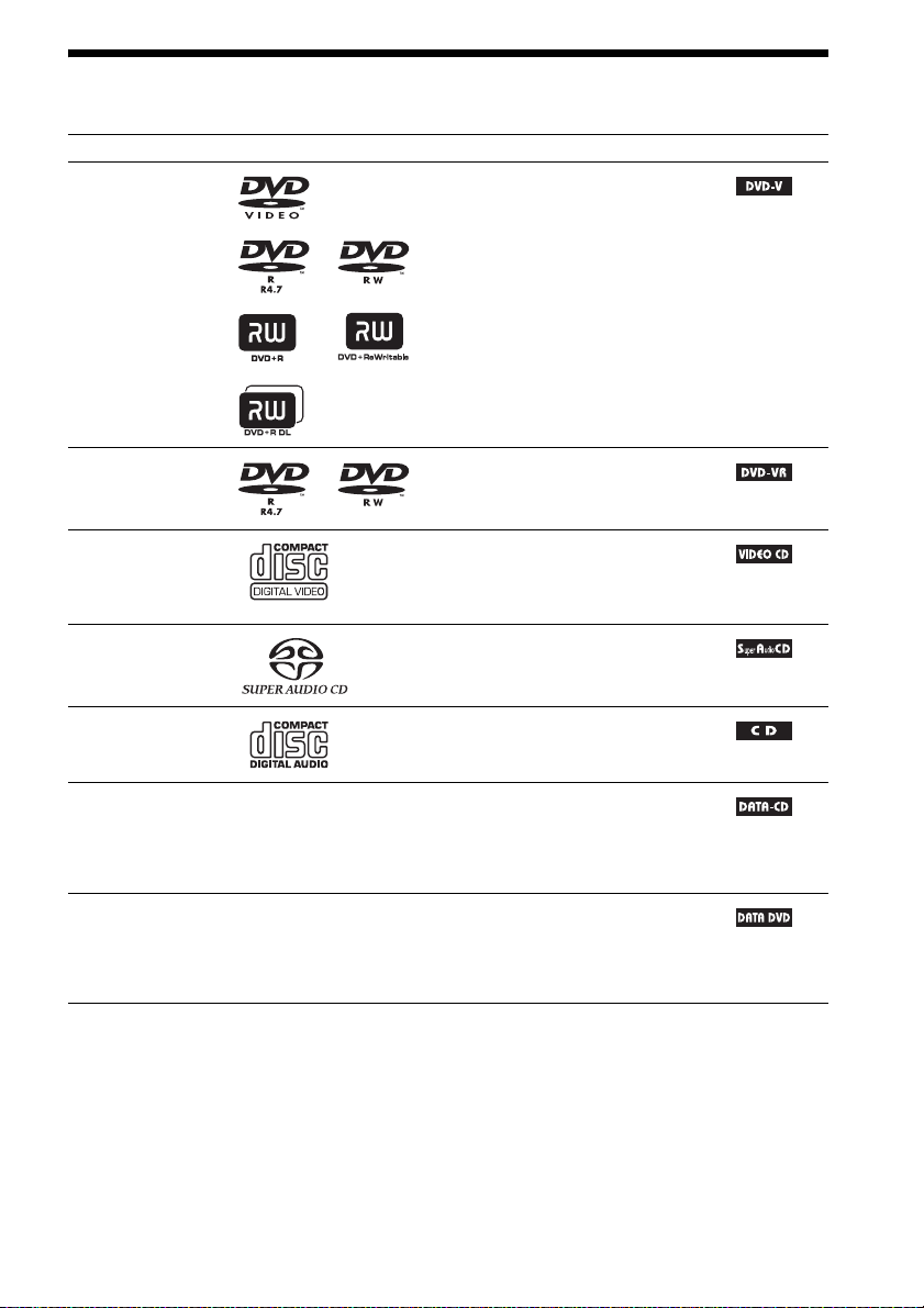
Playable Discs
Type Disc logo Characteristics Icon
DVD VIDEO • DVD VIDEO
• DVD-R/DVD-RW in DVD VIDEO
format or video mode
• DVD+R/DVD+RW in DVD VIDEO
format
VR (Video
Recording) mode
• DVD-R/DVD-RW in VR (Video
Recording) mode (except for DVD-R
DL)
VIDEO CD • VIDEO CD (Ver. 1.1 and 2.0 discs)
• Super VCD
• CD-R/CD-RW/CD-ROM in video CD
format or Super VCD format
Super Audio CD • Super Audio CD
CD • Audio CD
• CD-R/CD-RW in audio CD format
DATA CD – • CD-R/CD-RW/CD-ROM in DATA CD
format, containing MP3
image files
9660
2)
, and conforming to ISO
3)
Level 1/Level 2, or Joliet
files1) and JPEG
(extended format)
DATA DVD – • DVD-ROM/DVD-R/DVD-RW/
DVD+R/DVD+RW in DATA DVD
format, containing MP3 files1) and JPEG
image files2), and conforming to UDF
(Universal Disk Format)
1)
MP3 (MPEG1 Audio Layer 3) is a standard format defined by ISO/MPEG for compresses audio data. MP3 files
must be in MPEG1 Audio Layer 3 format.
2)
JPEG image files must conform to the DCF image file format. (DCF “Design rule for Camera File system”: Image
standards for digital cameras regulated by Japan Electronics and Information Technology Industries Association
(JEITA).)
3)
A logical format of files and folders on CD-ROMs, defined by ISO (International Organization for
Standardization).
US
5

Notes on discs
This product is designed to playback discs that conform to the Compact Disc (CD) standard.
DualDiscs and some of the music discs encoded with copyright protection technologies do not conform
to the Compact Disc (CD) standard, therefore, these discs may not be playable by this product.
Example of discs that the system cannot play
The system cannot play the following discs:
• CD-ROM/CD-R/CD-RW other than those recorded in the formats listed on page 5
• CD-ROM recorded in PHOTO CD format
• Data part of CD-Extra
• CD Graphics disc
• DVD Audio
• DATA CD/DATA DVD that does not contain MP3 files or JPEG image files
•DVD-RAM
•Blu-ray Disc
Also, the system cannot play the following discs:
• A DVD VIDEO with a different region code (page 7)
• A disc that has a non-standard shape (e.g., card, heart)
• A disc with paper or stickers on it
• A disc that has the adhesive of cellophane tape or a sticker still left on it
Note about CD-R/CD-RW/DVD-R/DVD-RW/DVD+R/DVD+RW
In some cases, CD-R/CD-RW/DVD-R/DVD-RW/DVD+R/DVD+RW cannot be played on this system
due to the recording quality or physical condition of the disc, or the characteristics of the recording
device and authoring software.
The disc will not play if it has not been correctly finalized. For more information, refer to the operating
instructions for the recording device.
Note that some playback functions may not work with some DVD+RWs/DVD+Rs, even if they have
been correctly finalized. In this case, view the disc by normal playback. Also some DATA CDs/DATA
DVDs created in Packet Write format cannot be played.
About Multi Session CD
• This system can play a Multi Session CD when an MP3 file is contained in the first session. Any
subsequent MP3 files recorded in later sessions can also be played back.
• This system can play a Multi Session CD when a JPEG image file is contained in the first session.
Any subsequent JPEG image files recorded in later sessions can also be played back.
• If MP3 files and JPEG image files in music CD format or video CD format are recorded in the first
session, only the first session will be played back.
US
6

Region code
Your system has a region code printed on the rear of the unit and will only play a DVD labeled with
the same region code.
A DVD VIDEO labeled will also play on this system.
If you try to play any other DVD VIDEO, the message [Playback prohibited by area limitations.] will
appear on the TV screen. Depending on the DVD VIDEO, no region code indication may be given even
though playing the DVD VIDEO is prohibited by area restrictions.
ALL
Note about playback operations of a DVD or VIDEO CD
Some playback operations on a DVD or VIDEO CD may be intentionally set by software producers.
Since this system will play a DVD or VIDEO CD according to the disc contents the software producers
designed, some playback features may not be available. Be sure to read the operating instructions
supplied with the DVD or VIDEO CD.
US
7
Getting Started
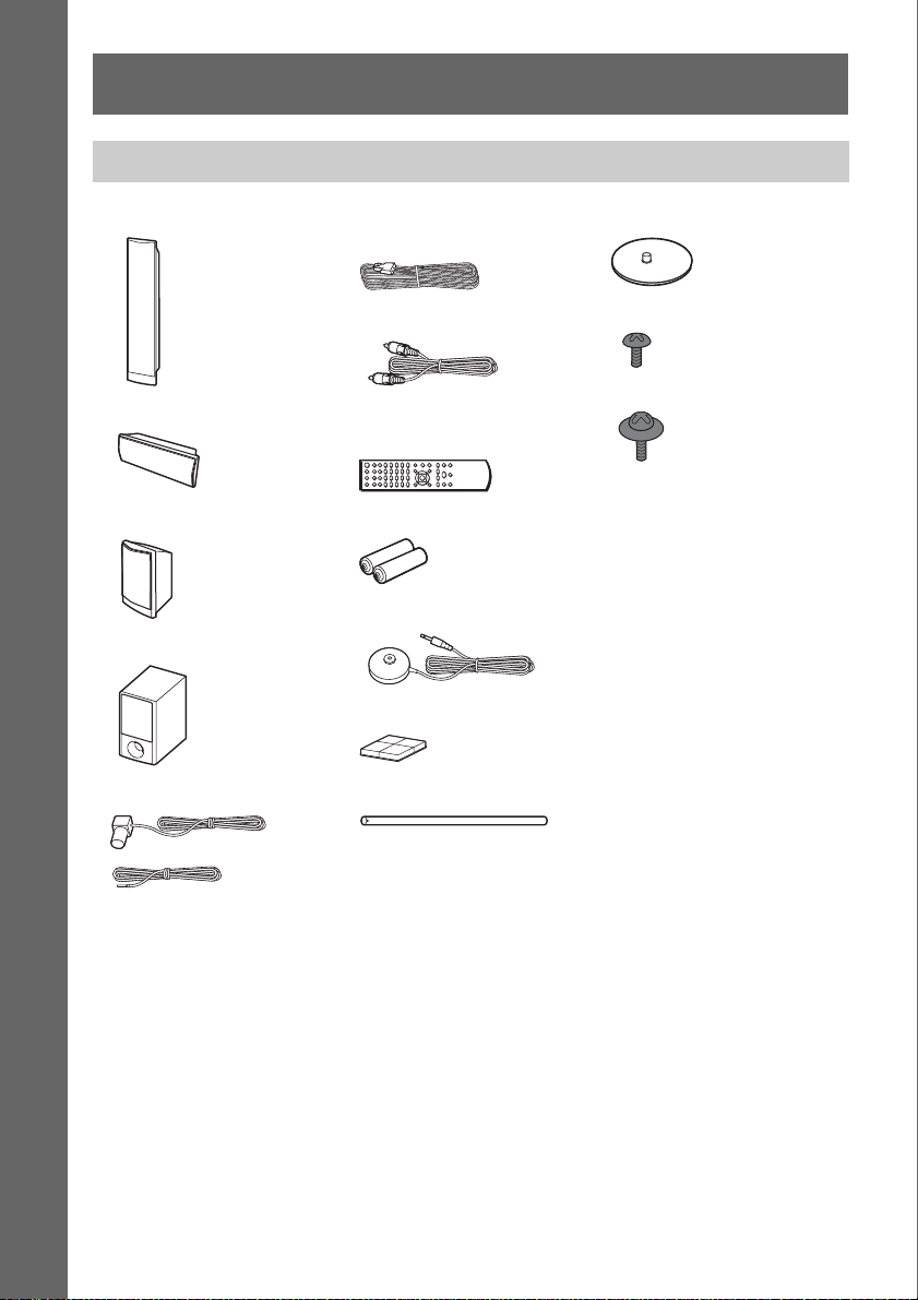
Unpacking
• Front speakers (2)
Getting Started
• Center speaker (1)
• Surround speakers (2)
• Subwoofer (1)
• FM wire antenna (aerial) (1)
• Speaker cords (6, red/white/
green/gray/blue/purple)
•Video cord (1)
• Remote commander
(remote) (1)
• R6 (size AA) batteries (2)
• Calibration mic (1)
• Foot pads (1 set)
•Posts (2)
• Bases (2)
• Screws (black) (4)
• Screws (with washer) (4)
• Operating Instructions
• Quick Setup Guide
• Setup Disc (DVD)
or
US
8
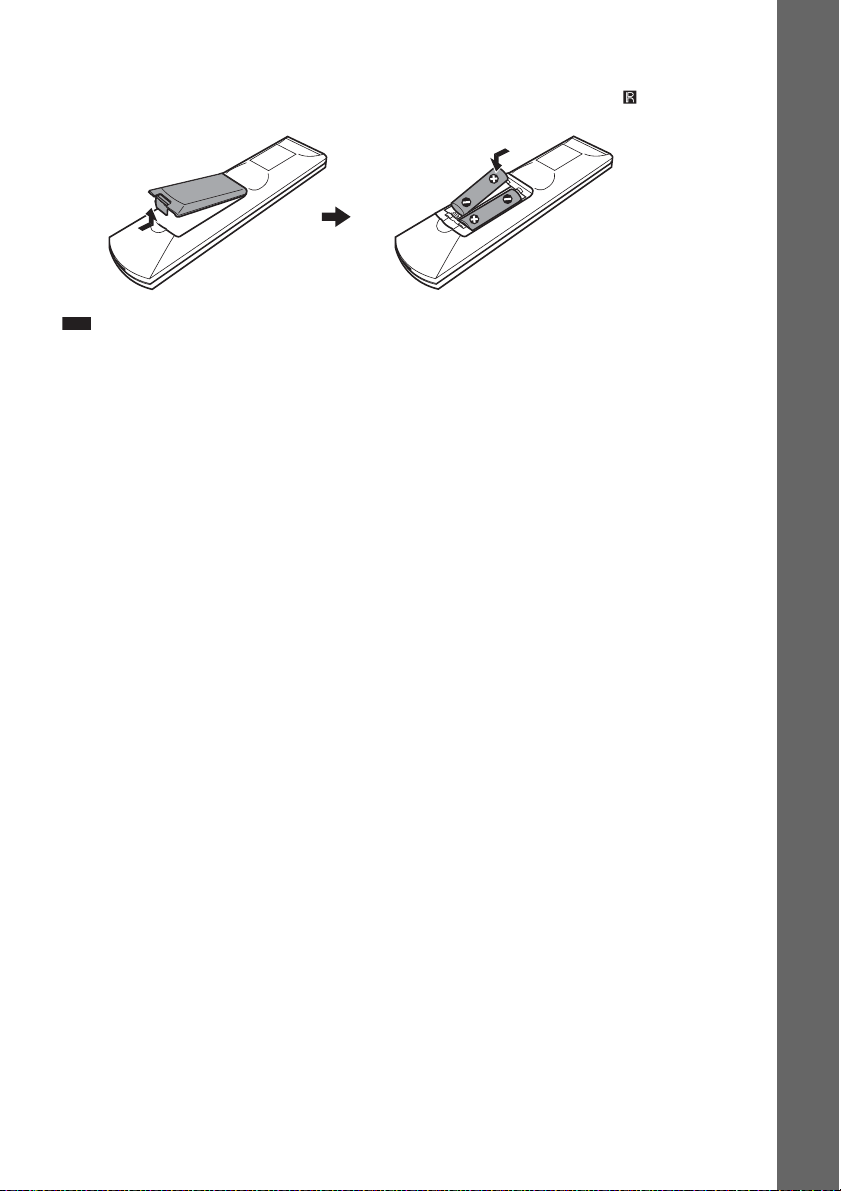
Inserting batteries into the remote
Insert two R6 (size AA) batteries (supplied) by matching the 3 and # ends on the batteries to the
markings inside the compartment. To use the remote, point it at the remote sensor on the unit.
Note
• Do not leave the remote in an extremely hot or humid place.
• Do not use a new battery with an old one.
• Do not drop any foreign object into the remote casing, particularly when replacing the batteries.
• Do not expose the remote sensor to direct sunlight or lighting apparatus. Doing so may cause a malfunction.
• If you do not intend to use the remote for an extended period of time, remove the batteries to avoid possible damage
from battery leakage and corrosion.
Getting Started
US
9
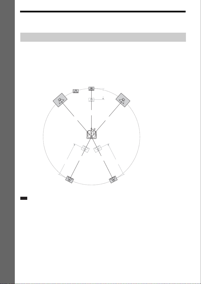
Step 1: Installing the System
Positioning the system
For the best possible surround sound, place all speakers at the same distance from the listening position
Getting Started
(A). The distance can be between 1.0 to 7.0 meters.
If you cannot place the center speaker and surround speakers at the same distance as (A), you can move
the center speaker up to 1.6 meters closer to the listening position (B), and the surround speakers up
to 5.0 meters closer to the listening position (C).
The subwoofer can be placed anywhere in the room.
Subwoofer
Front left speaker (L)
Center speaker
B
Front right speaker (R)
A
A
A
Surround left speaker (L)
Note
• Use caution when placing the speakers and/or speaker stands attached to the speakers on a specially treated (waxed,
oiled, polished, etc.) floor, as staining or discoloration may result.
• Do not lean or hang on a speaker, as it may fall down.
A
A
CC
Surround right speaker (R)
10
US
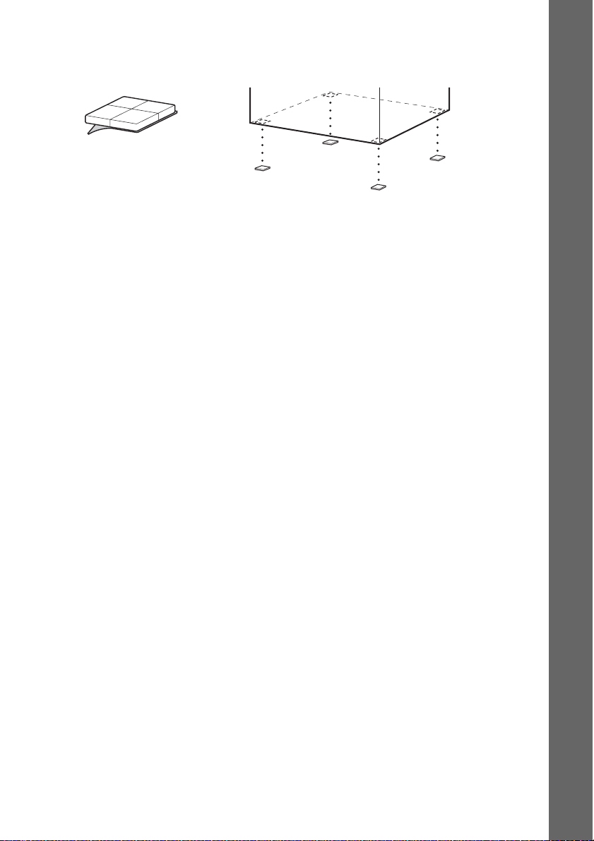
Attaching the foot pads to the subwoofer
Attach the foot pads (supplied) to the bottom of the subwoofer to stabilize the subwoofer and prevent
it from slipping.
,
Remove the foot pads from
the protective cover.
Getting Started
11
US
p
Assembling the speakers
Before connecting the speakers, attach the speaker stand to the speaker.
(For the front speakers)
Use the parts as follows:
• Front speakers (2)
Getting Started
• Speaker cords (2, red/white)
• Posts (2)
• Bases (2)
• Screws (black) (4)
• Screws (with washer) (4)
For details of how to connect the speaker cords to the SPEAKER jacks, see page 19.
Note
• Spread a cloth on the floor to avoid damaging the floor when you assemble the speakers.
Ti
• You can use the speaker without the speaker stand by installing it on the wall (page 17).
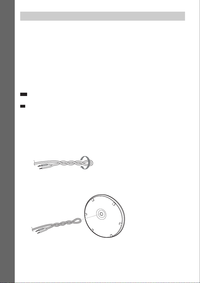
1 Fold back the speaker cord and twist it together.
The connector and color tube of the speaker cords are the same color as the label of the jacks to be
connected.
Use the speaker cords as follows:
• Front left speaker (L): White
• Front right speaker (R): Red
Speaker cord
2 Thread the speaker cord through the bottom hole in the base.
Bottom of the base
Speaker cord
US
12
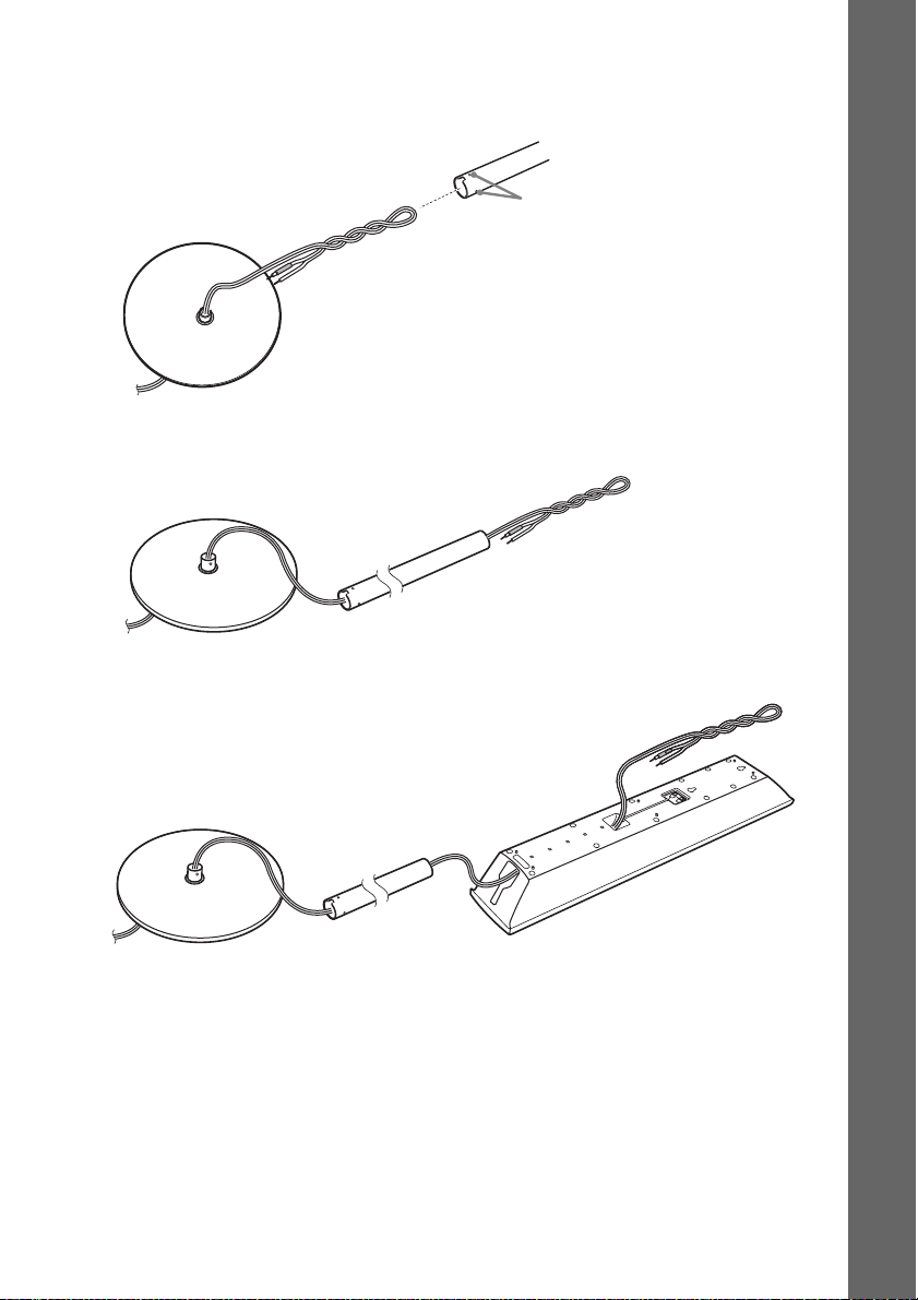
3 Thread the speaker cord through the hole in the post.
Be careful with the orientation of the post. Thread the speaker cord into the end of the post that has
two holes.
Post
Getting Started
Top of the base
Two holes
4 Thread the speaker cord through the post and out the opposite end.
Base
Post
Speaker cord
5 Thread the speaker cord through the hole on the bottom of the speaker.
Speaker cord
Base
Post
Rear of the speaker
13
US
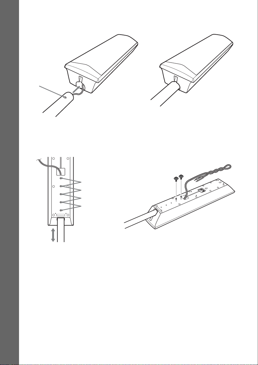
6 Insert the post into the hole on the bottom of the speaker so that the screw on the post
faces the front of the speaker.
Speaker
Getting Started
Screw
Post
,
7 Adjust the height of the speaker, then secure the post with two screws (with washer).
You can change the height of the speaker depending on the screw positions. Adjust the screw holes
of the post to the holes on the rear of the speaker (A, B, C, or D). The height of the speaker can
be increased by using the holes in order from A to D.
Rear of the speaker
A
B
C
D
Post
Example: Lowest position
,
Secure two screws (with
washer).
14
US
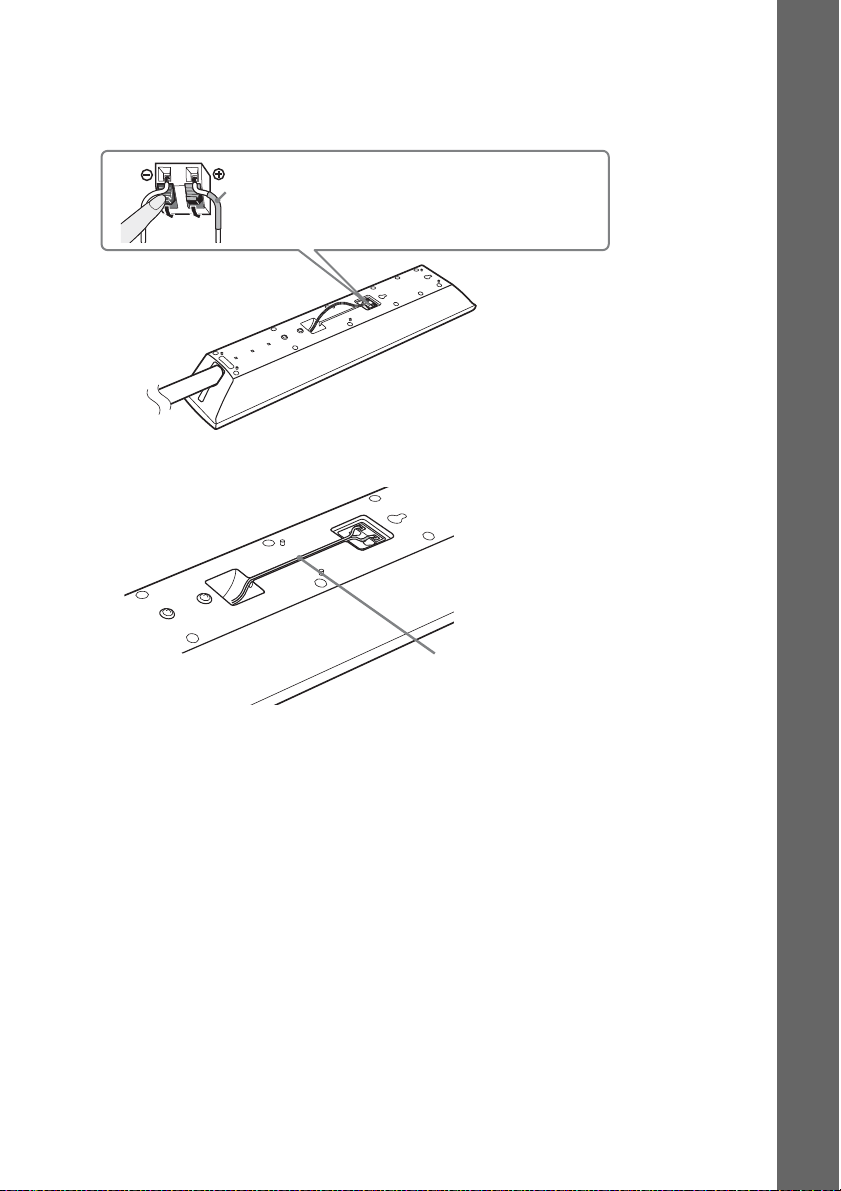
8 Connect the speaker cords to the speaker.
Extend the twisted speaker cord as before.
Be sure to match the speaker cords to the appropriate terminals on the speakers: the speaker cord
with the color tube to 3, and the speaker cord without the color tube to #.
Color tube
Front left speaker (L): White
Front right speaker (R): Red
Rear of the speaker
9 Secure the speaker cord by running it through the slot.
Rear of the speaker
Getting Started
Speaker cord
15
US
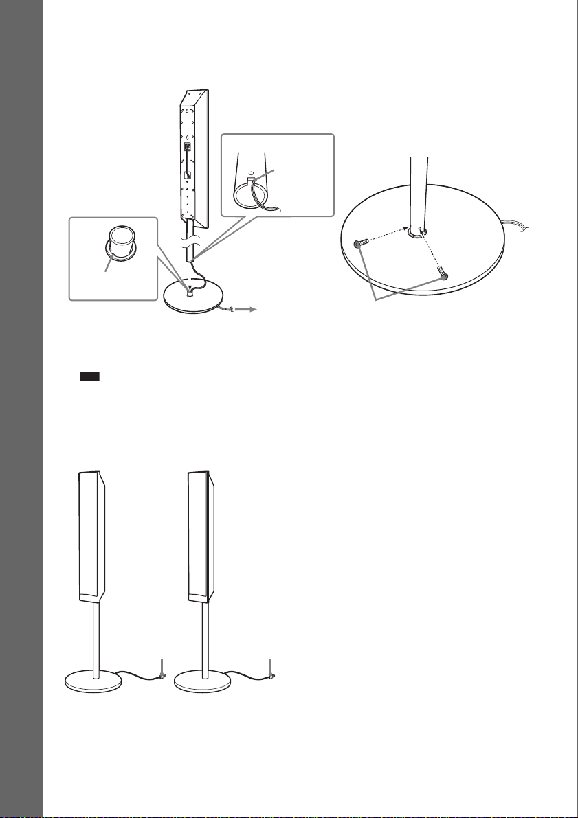
10 Attach the post to the base.
Insert the post so that the slot on the lower part of the post aligns with the projection of the base,
then secure the post with two screws (black).
Getting Started
Projection
Pull the speaker cord in the direction of the
arrow so that it does not get caught when
attaching the post to the base.
Note
• Make sure that the slot on the post aligns with the projection of the base by rotating the post slightly.
Fully-assembled illustration
Front left speaker (L):
White label
Post
Base
Front right speaker (R):
Red label
Slot
,
Screws
(black)
16
White
US
Red
Installing the speakers on a wall
Caution
• Contact a screw shop or installer for information regarding the wall material or screws to be used.
• Use screws that are suitable for the wall material and strength. As a plaster board wall is especially fragile, attach
the screws securely to a beam. Install the speakers on a vertical and flat wall where reinforcement is applied.
• Sony is not responsible for accidents or damage caused by improper installation, insufficient wall strength or
improper screw installation, natural calamity, etc.
Before installing the speakers on a wall, connect the speaker cord to the speaker.
Be sure to match the speaker cords to the appropriate terminals on the speakers: the speaker cord with
the color tube to 3, and the speaker cord without the color tube to #.
Color tube
Front left speaker (L): White
Front right speaker (R): Red
Center speaker: Green
Surround left speaker (L): Blue
Surround right speaker (R): Gray
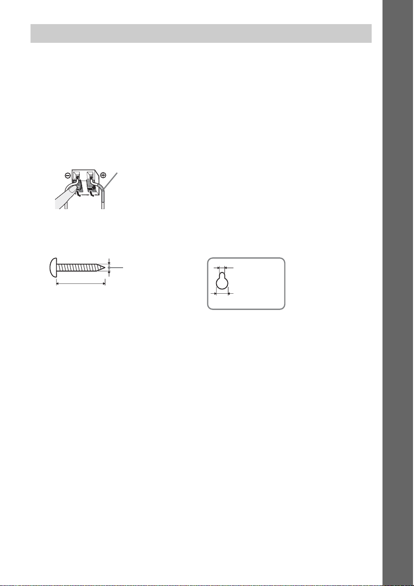
1 Prepare screws (not supplied) that are suitable for the hole on the back of each speaker.
See the illustrations below.
Getting Started
30 mm (1 3/16 inches)
4 mm (
5
/32 inch)
5 mm
7
/32 inch)
(
10 mm
13
/32 inch)
(
Hole on the back of
the speaker
17
US
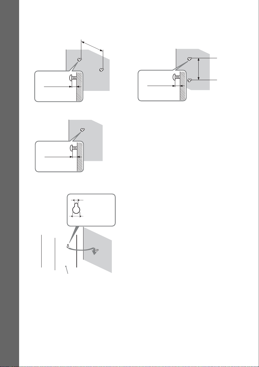
2 Fasten the screws to the wall.
For the center speaker
Getting Started
8 to 10 mm
11
/32 to 13/32
(
For the surround speakers
11
/32 to 13/32
(
inch
8 to 10 mm
inch
)
)
3 Hang the speakers on the screws.
5 mm
7
(
145 mm
(5
/32 inch)
3
/4 inches)
For the front speakers
11
(
/32 to 13/32
Hole on the back of
the speaker
8 to 10 mm
inch
101.6 mm
(
4 inches
)
)
18
10 mm
13
/32 inch)
(
Rear of the speaker
US
Step 2: Connecting the System
For connecting the system, read the information on the following pages.
Do not connect the AC power cord (mains lead) of the unit to a wall outlet (mains) until all the other
connections are made.
Note
• When you connect another component with a volume control, turn down the volume of the other components to a
level where sound is not distorted.
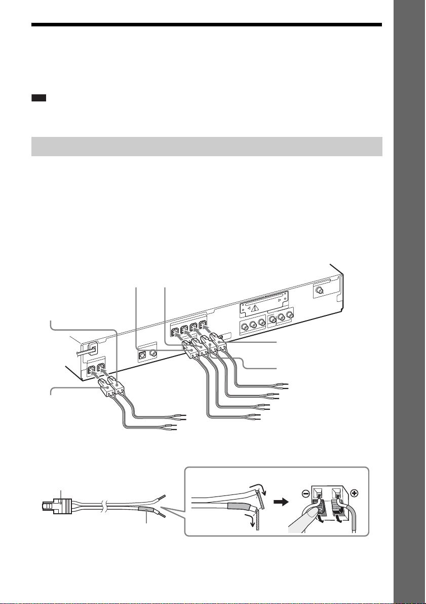
Connecting the speakers
The connector of the speaker cords and the color tube are color-coded depending on the type of speaker.
Connect the speaker cords to match the color of the SPEAKER jacks of the unit.
Be sure to match the speaker cords to the appropriate terminals on the speakers: the speaker cord with
the color tube to 3, and the speaker cord without the color tube to #. Do not catch the speaker cord
insulation (rubber covering) in the speaker terminals.
To connect speaker cords to the unit
When connecting to the unit, insert the connector until it clicks.
Getting Started
Red
(Front right speaker (R))
White
(Front left speaker (L))
Purple
(Subwoofer)
O
E
ID
/V
V
T
DIGITAL IN
R
E
K
A
E
P
S
R
E
F
O
O
W
B
U
S
CENTER
COAXIAL
OPTICAL
A
E
P
S
FRONT R FRONT L SUR R
M
D
H
R
E
K
SUR L
T
U
I O
DC5V
0.7A MAX
T
R
O
P
M
D
Green
(Center speaker)
To connect speaker cords to the speaker
Connector
Color tube
(–)
(+)
A
N
N
E
T
N
A
COAXIAL 75
FM
EZW-T100
L
AUDIO IN
R
O
E
ID
/V
V
O
T
E
ID
V
T
U
R
O
/C
R
P
B
T
U
/C
B
O
P
O
E
ID
V
T
Y
N
E
N
O
P
M
O
C
Blue
(Surround left speaker (L))
Gray
(Surround right speaker (R))
Rear of the speaker
19
US
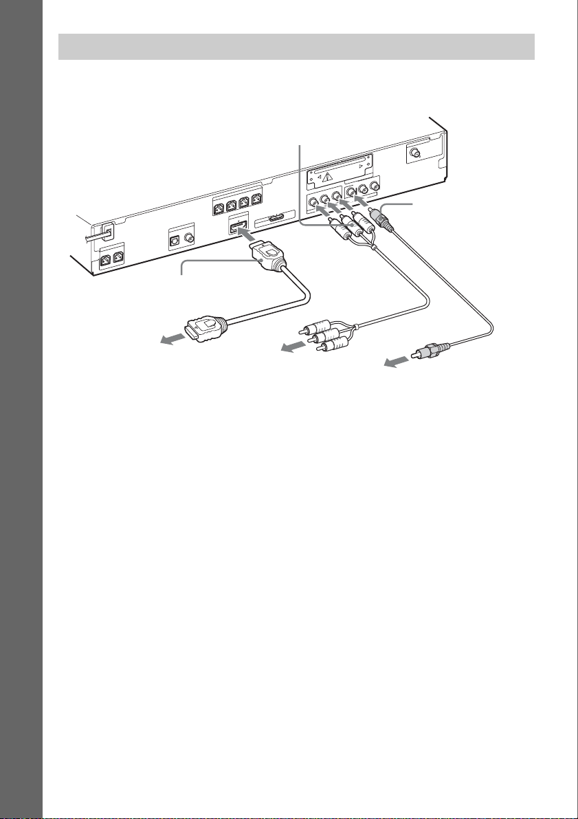
Connecting the TV (Video connection)
This connection sends a video signal to the TV.
Depending on the jacks on your TV, select the connection method.
Getting Started
C Component video cable
(not supplied)
EZW-T100
R
E
K
SUR L
A
E
P
S
SUR R
FRONT R FRONT L
T
U
I O
M
D
H
T
R
O
P
M
O
E
ID
/V
V
T
DIGITAL IN
R
E
K
A
E
P
S
R
E
F
O
O
W
B
U
S
CENTER
COAXIAL
OPTICAL
D
DC5V
0.7A MAX
B
/C
B
P
O
E
ID
V
T
Y
N
E
N
O
P
M
O
C
L
AUDIO IN
R
O
E
ID
/V
V
O
T
E
ID
V
T
U
R
O
/C
R
P
T
U
O
A
N
N
E
T
N
A
COAXIAL 75
FM
A Video cord (supplied)
B HDMI cable (not supplied)
To the HDMI IN jack
of the TV.
To the component
video input jacks of
the TV.
To the video input jack of
the TV.
Method 1: Video cord (A) connection
This is the basic connection.
Method 2: HDMI* cable (B) and video cord (A) connection
If your TV has an HDMI jack, connect to the TV both with an HDMI cable and video cord. Picture
quality will be improved compared to using only the video cord connection.
When connecting with the HDMI cable, you need to select the type of output signal (page 28).
To view images from the DIGITAL MEDIA PORT adapter, you need to connect to the TV with the
video cord. Video signals from the DIGITAL MEDIA PORT adapter are not output via the HDMI OUT
jack.
* HDMI (High-Definition Multimedia Interface)
Method 3: Component video cable (C) and video cord (A) connection
If your TV does not have an HDMI jack, but has component video input jacks, connect to the TV both
with a component video cable and video cord. Picture quality will be improved compared to using only
the video cord connection.
When connecting with the component video cable, you need to set the type of output signal to
progressive format (page 28).
To view images from the DIGITAL MEDIA PORT adapter, you need to connect to the TV with the
video cord. Video signals from the DIGITAL MEDIA PORT adapter are not output via the
COMPONENT VIDEO OUT jack.
US
20
p
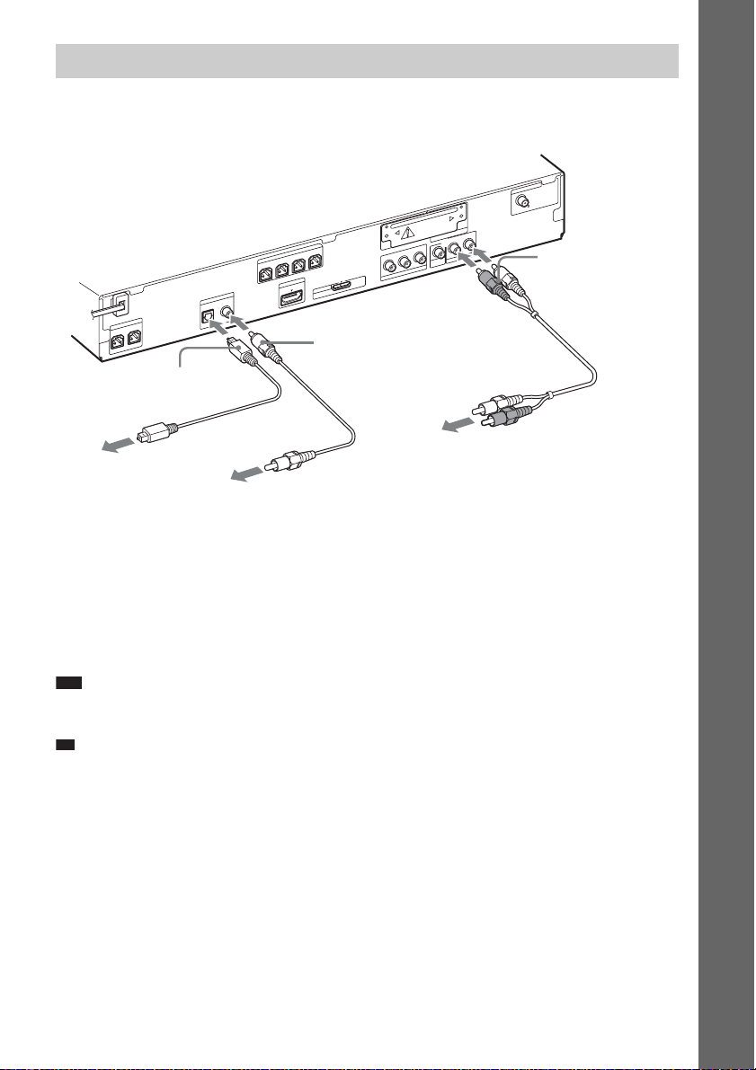
Connecting the TV (Audio connection)
This connection sends an audio signal to the unit from the TV. To listen to TV sound via the system,
perform this connection.
A
N
N
E
T
N
A
COAXIAL 75
FM
EZW-T100
R
E
K
SUR L
A
E
P
S
SUR R
FRONT R FRONT L
T
U
I O
M
D
O
E
ID
/V
V
T
DIGITAL IN
R
E
K
A
E
P
S
R
E
F
O
O
W
B
U
S
CENTER
COAXIAL
OPTICAL
H
DC5V
0.7A MAX
T
R
O
P
M
D
F Digital coaxial cord (not
supplied)
P
B
/C
B
O
P
O
E
ID
V
T
Y
N
E
N
O
P
M
O
C
E Digital optical cord (not
supplied)
To the audio out jacks of
To the digital optical out
jack of the TV.
To the digital coaxial out jack
the TV.
of the TV.
Method 1: Audio cord (D) connection
This is the basic connection and sends an analog audio signal.
L
AUDIO IN
R
O
E
ID
/V
V
O
T
E
ID
V
T
U
R
O
/C
R
T
U
D Audio cord (not
supplied)
Getting Started
Method 2: Digital optical cord (E) or digital coaxial cord (F) connection
When the TV has a digital optical or coaxial output jack, you can improve sound quality by connecting
with a digital optical or coaxial cord in addition to an audio cord connection.
Note
• The system can accept both digital and analog signals. Digital signals have priority over analog signals. (COAXIAL
has priority over OPTICAL.) If the digital signal ceases, the analog signal will be processed after 2 seconds.
Ti
• You can connect another component, such as a VCR, digital satellite receiver, or PlayStation, to the TV/VIDEO
(AUDIO IN R/L) jacks or DIGITAL IN OPTICAL/COAXIAL jacks instead of the TV.
21
US
p
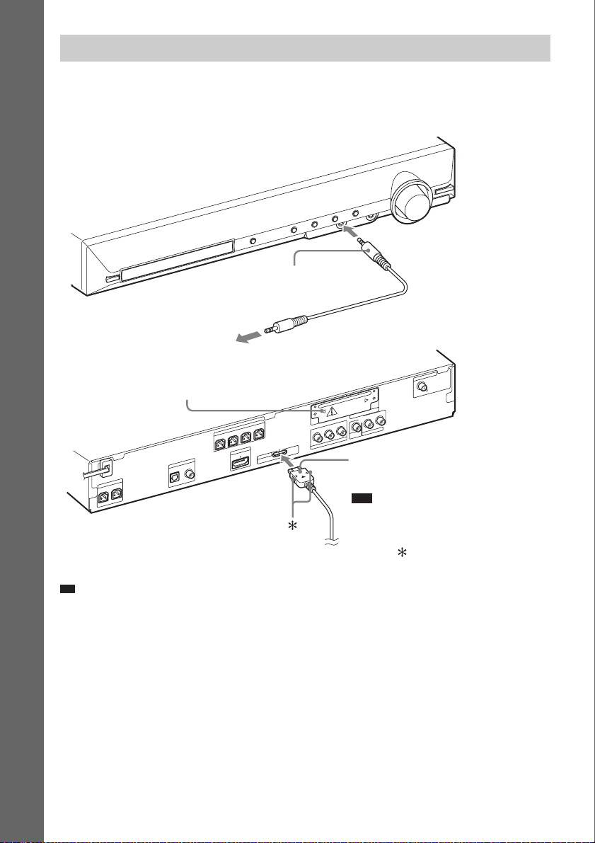
Connecting the other components
You can enjoy connected components via the system’s speakers.
Portable audio source (not supplied): G
DIGITAL MEDIA PORT adapter (not supplied): H
Getting Started
G Stereo mini-plug cord
(not supplied)
To a portable audio source
EZW-T100 slot (See “Wireless
system options”.)
R
E
K
A
E
P
S
FRONT L SUR R SUR L
FRONT R
T
U
I O
M
D
O
E
ID
/V
V
T
DIGITAL IN
R
E
K
A
E
P
S
R
E
F
O
O
W
B
U
S
CENTER
COAXIAL
OPTICAL
H
DC5V
0.7A MAX
T
R
O
P
M
D
A
N
N
E
T
N
A
COAXIAL 75
FM
EZW-T100
L
AUDIO IN
R
O
E
ID
/V
V
O
T
E
ID
V
T
U
R
O
/C
R
P
B
T
U
/C
B
O
P
O
E
ID
V
T
Y
N
E
N
O
P
M
O
C
H DIGITAL MEDIA PORT adapter
(page 62)
Note
• Connect the DIGITAL MEDIA PORT
adapter so that the V marks are aligned.
When disconnecting, pull out while
pressing .
Ti
• You can connect another component, such as a VCR, digital satellite receiver, or PlayStation, to the TV/VIDEO
(AUDIO IN R/L) jacks or DIGITAL IN OPTICAL/COAXIAL jacks instead of the TV.
Wireless system options
By using an S-AIR product (not supplied), you can enjoy wireless performance by transmission from
the system. For details, see “Using an S-AIR Product” (page 63) or refer to the operating instructions
of the S-AIR product.
US
22
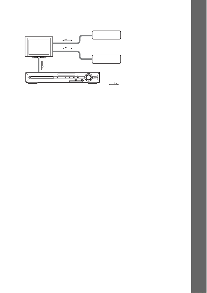
If your TV has multiple audio/video inputs
You can enjoy sound with the speakers of the system through the connected TV. Connect the
components as follows.
TV
System
VCR, digital satellite receiver,
PlayStation, etc.
VCR, digital satellite receiver,
PlayStation, etc.
:Signal flow
Select the component on the TV. For details, refer to the operating instructions of the TV.
If the TV does not have multiple audio/video inputs, a switcher will be necessary to receive sound from
more than one component.
Getting Started
23
US
p
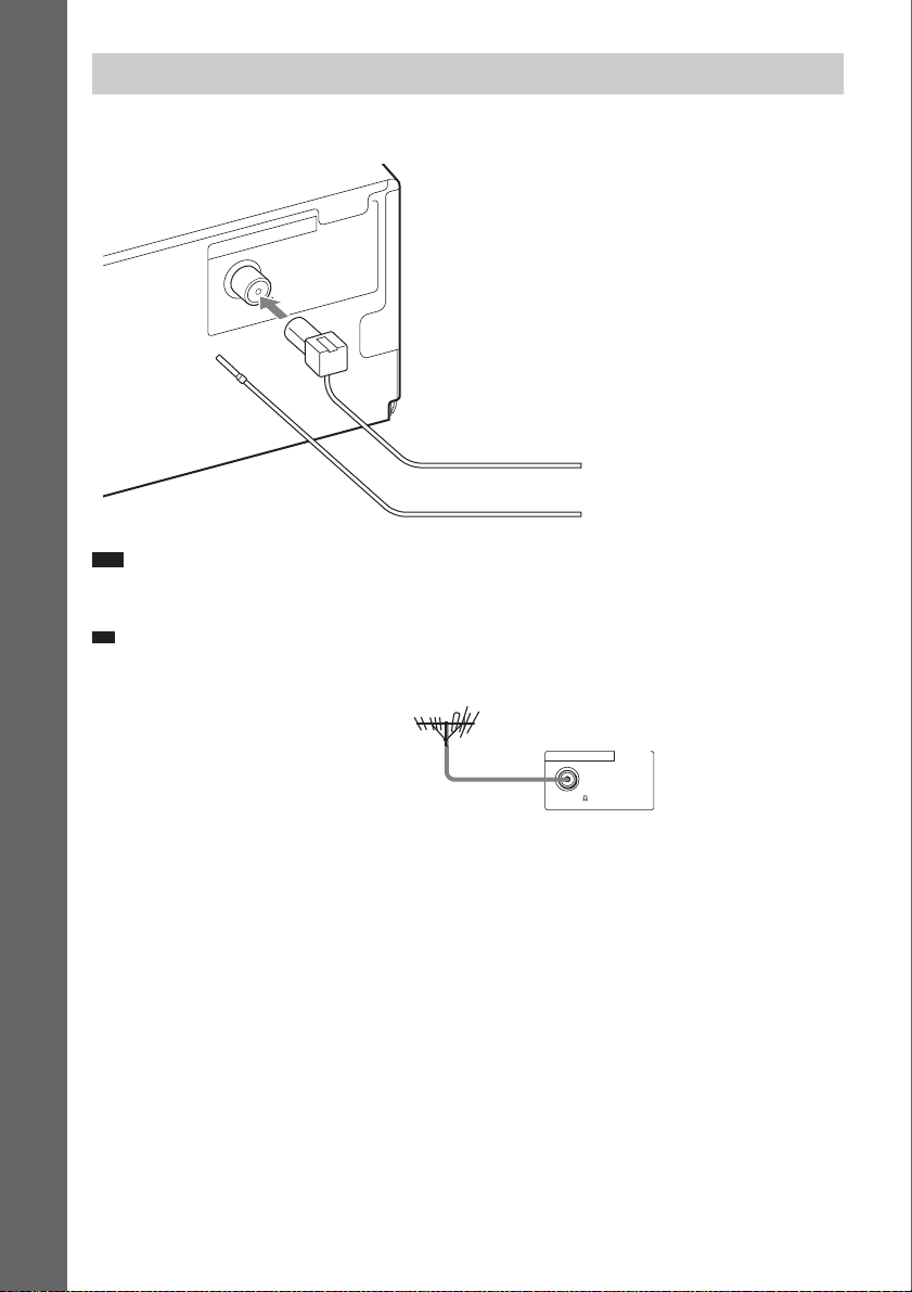
Connecting the antenna (aerial)
Getting Started
ANTENNA
COAXIAL 75
FM
or
FM wire antenna (aerial)
(supplied)
Note
• Be sure to fully extend the FM wire antenna (aerial).
• After connecting the FM wire antenna (aerial), keep it as horizontal as possible.
Ti
• If you have poor FM reception, use a 75-ohm coaxial cable (not supplied) to connect the unit to an outdoor FM
antenna (aerial) as shown below.
Outdoor FM antenna (aerial)
Unit
ANTENNA
COAXIAL 75
FM
US
24
p
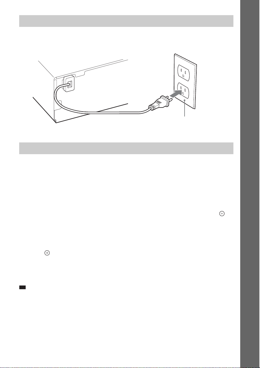
Connecting the AC power cord (mains lead)
Before connecting the AC power cord (mains lead) of the unit to a wall outlet (mains), connect all the
speakers to the unit.
Wall outlet (mains): The shape of the wall outlet (mains)
differs depending on the area.
About the demonstration
After connecting the AC power cord (mains lead), the demonstration appears in the front panel display.
Setting the demonstration mode to on/off
1 Press [/1 on the unit.
The system turns on.
2 Press SYSTEM MENU.
3 Press X/x repeatedly until “DEMO” appears in the front panel display, then press or
c.
4 Press X/x to select a setting.
• “DEMO ON”: On.
• “DEMO OFF”: Off.
5 Press .
The setting is made.
6 Press SYSTEM MENU.
The system menu turns off.
Ti
• When you purchase the system new, or if the system is at its factory default settings (ex., after performing “COLD
RESET” (page 77)), you can turn off the demonstration simply by pressing [/1 on the remote (except for U.S.
models).
Getting Started
US
25
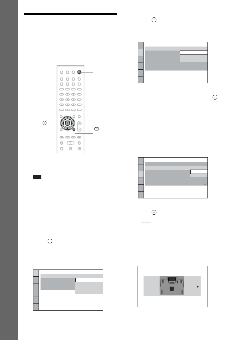
Step 3: Performing the Quick Setup
5 Press X/x to select a language, then
press .
The Setup Display for selecting the aspect
ratio of the TV to be connected appears.
Follow the Steps below to make the basic
adjustments for using the system.
Displayed items vary depending on the area.
Getting Started
C/X/x/c,
1 Turn on the TV.
2 Press [/1.
Note
• Make sure that the function is set to “DVD”
(page 29).
3 Switch the input selector on your TV so
that the signal from the system
appears on the TV screen.
[Press [ENTER] to run QUICK SETUP.]
appears at the bottom of the TV screen. If
this message does not appear, recall the
Quick Setup display (page 27).
4 Press without inserting a disc.
The Setup Display for selecting the
language used in the on-screen display
appears.
"/1
DISPLAY
VIDEO SETUP
TV TYPE:
PROGRESSIVE
4:3 OUTPUT:
BLACK LEVEL:
BLACK LEVEL
PAUSE MODE:
(COMPONENT OUT)
4:3 LETTER BOX
(COMPONENT OUT)
16:9
16:9
:
4:3 PAN SCAN
OFF
:
AUTO
6 Press X/x to select the setting that
matches your TV type, then press .
• [16:9]: For a wide-screen TV or a 4:3
standard TV with a wide-screen mode
(page 51)
• [4:3 LETTER BOX] or [4:3 PAN SCAN]:
For a 4:3 standard TV (page 51)
The Setup Display for the Control for
HDMI function appears.
HDMI SETUP
HDMI RESOLUTION:
CONTROL FOR HDMI:
VOLUME LIMIT:
YCBCR/RGB(HDMI):
AUDIO(HDMI):
JPEG RESOLUTION:
AUTO
(1920x1080p)
ON
ON
OFF
OFF
SD
7 Press X/x to select the setting, then
press .
• [ON]: The Control for HDMI function
(page 60) is set to on.
• [OFF]: The Control for HDMI function is
set to off.
The Setup Display for selecting the speaker
formation appears.
LANGUAGE SETUP
OSD:
MENU:
AUDIO:
SUBTITLE:
US
26
ENGLISH
ENGLISH
FRENCH
SPANISH
PORTUGUESE
SPEAKER FORMATION
STANDARD
8 Press C/c to select the speaker
formation image as the speakers are
actually positioned, then press .
For details, see “Getting Optimal Surround
Sound for a Room” (page 69).
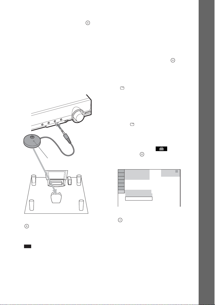
9 Connect the calibration mic (supplied)
to the A.CAL MIC jack on the front
panel.
Set up the calibration mic at ear level using
a tripod, etc. (not supplied).
The front of each speaker should face the
calibration mic, and there should be no
obstruction between the speakers and the
calibration mic.
Calibration mic
location, such as another room, proper
measurement will not be obtained.
• The environment of the room in which the
system is installed may affect measurements.
When the measurements differ considerably
from the status of the speaker installation,
perform the speaker settings manually by
following “Settings for the speakers” (page 54).
11Unplug the calibration mic, press C/c
to select [YES], then press .
Quick Setup is finished. All connections
and setup operations are complete.
To quit the Quick Setup
Press DISPLAY in any Step.
To recall the Quick Setup display
1 Press FUNCTION +/– repeatedly until
“DVD” appears in the front panel
display.
2 Press DISPLAY while the system is
in stop mode.
The Control Menu display appears on the
TV screen.
3 Press X/x to select [SETUP],
then press .
The options for [SETUP] appear.
Getting Started
10 Press C/c to select [YES], then press
.
[AUTO CALIBRATION] starts.
Be quiet during the measurement.
Note
• Loud test sounds are output when [AUTO
CALIBRATION] starts. You cannot turn the
volume down. Give consideration to children
and neighbors.
• Before [AUTO CALIBRATION], install the
surround amplifier in the appropriate location. If
you install the sur round amplifier in an improper
94( 99)
1( 1)
T 0: 01: 08
CUSTOM
CUSTOM
QUICK
DVD VIDEO
4 Press X/x to select [QUICK], then press
.
The Quick Setup display appears.
27
US

Setting the type of video output to match your TV
Depending on the connection of the TV
(page 20), select the type of video output of the
system.
Getting Started
To select the type of video signal
output from the HDMI OUT jack
When you connect the unit and the TV with an
HDMI cable, select the type of video signals
output from the HDMI OUT jack.
For details, refer also to the operating
instructions supplied with the TV/projector, etc.
1 Press FUNCTION +/– repeatedly until
“DVD” appears in the front panel
display.
2 Press DISPLAY while the system is
in stop mode.
The Control Menu display appears on the
TV screen.
3 Press X/x to select [SETUP],
then press .
The options for [SETUP] appear.
4 Press X/x to select [CUSTOM], then
press .
The Setup Display appears.
5 Press X/x to select [HDMI SETUP], then
press .
The options for [HDMI SETUP] appear.
6 Press X/x to select [HDMI
RESOLUTION], then press .
7 Press X/x to select the desired setting,
then press .
• [AUTO (1920
outputs the optimal video signal for the
connected TV.
• [1920
× 1080i* video signals.
• [1280
720p* video signals.
× 480p]**: The system outputs 720 ×
• [720
480p* video signals.
* i: interlace, p: progressive
× 1080p)]: The system
× 1080i]: The system outputs 1920
× 720p]: The system outputs 1280 ×
** Depending on the area, [720 × 480/576p] may
appear.
Does your TV accept progressive
signals?
Progressive is a method for displaying TV
images which reduces flickering and sharpens
the image. To use this method, you need to
connect to a TV that accepts progressive signals.
1 Press FUNCTION +/– repeatedly until
“DVD” appears in the front panel
display.
2 Press DISPLAY while the system is
in stop mode.
The Control Menu display appears on the
TV screen.
3 Press X/x to select [SETUP],
then press .
The options for [SETUP] appear.
4 Press X/x to select [CUSTOM], then
press .
The Setup Display appears.
5 Press X/x to select [VIDEO SETUP],
then press .
The options for [VIDEO SETUP] appear.
6 Press X/x to select [PROGRESSIVE
(COMPONENT OUT)], then press .
7 Press X/x to select the desired setting,
then press .
[OFF]: The system does not output
progressive signals. Select this setting
when:
– your TV does not accept progressive
signals, or,
– your TV is connected via jacks other than
the COMPONENT VIDEO OUT jacks.
[ON]: The system outputs progressive
signals. Select this setting when:
– your TV accepts progressive signals,
and,
– the TV is connected via the
COMPONENT VIDEO OUT jacks.
When you select [ON], the confirmation
display appears. Follow the Steps below.
28
US
8 Press C/c to select [START], then
press .
The system outputs a progressive signal for
5 seconds. Check that the screen is
displayed correctly.
9 Press C/c to select [YES], then press
.
The system outputs a progressive signal.
When you select [NO], the system does not
output a progressive signal.
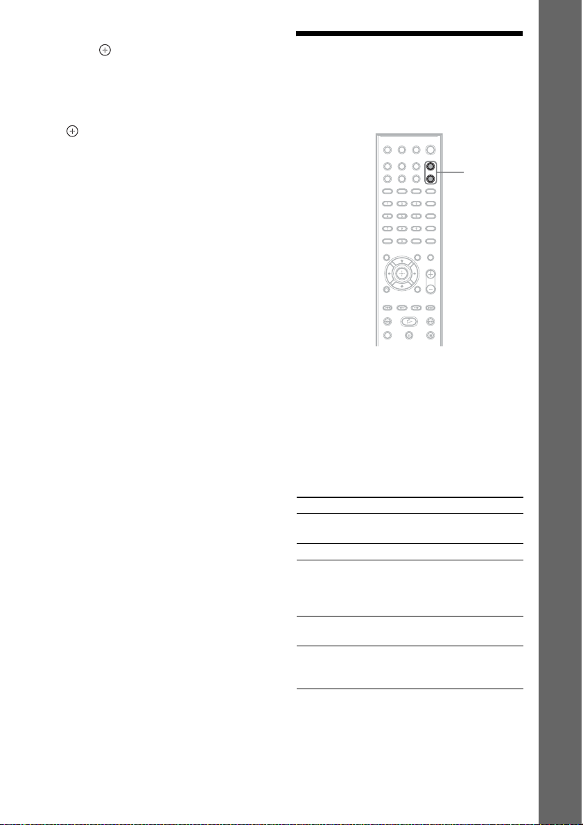
Step 4: Selecting the Source
You can select the playback source.
FUNCTION
+/–
Press FUNCTION +/– repeatedly until the
desired function appears in the front panel
display.
Each time you press FUNCTION +/–, the
function changes as follows.
Getting Started
“DVD” y “TUNER FM” y “TV/VIDEO”
y “DMPORT” y “AUDIO” y …
Function Source
“DVD” Disc that is played by the
system
“TUNER FM” FM radio (page 57)
“TV/VIDEO” TV or component that is
connected to the TV/
VIDEO jacks on the rear
panel
“DMPORT” DIGITAL MEDIA PORT
adapter (page 62)
“AUDIO” Portable audio source that
is connected to the AUDIO
IN jack on the front panel
29
US

Step 5: Enjoying Surround Sound
You can enjoy surround sound simply by selecting one of the system’s pre-programmed decoding
modes. They bring the exciting and powerful sound of movie theaters into your home.
Getting Started
SYSTEM MENU
X/x/c,
Enjoying TV sound with the 5.1 channel surround sound effect
1 Press SYSTEM MENU.
2 Press X/x repeatedly until “DEC. MODE” appears in the front panel display, then press
or c.
3 Press X/x repeatedly until “PRO LOGIC” appears in the front panel display.
4 Press .
The setting is made.
5 Press SYSTEM MENU.
The system menu turns off.
Note
• When TV program sound is monaural, sound is output only from the center speaker.
Selecting surround sound effects based on your listening preference
1 Press SYSTEM MENU.
2 Press X/x repeatedly until “DEC. MODE” appears in the front panel display, then press
or c.
3 Press X/x repeatedly until the surround sound effect you want appears in the front panel
display.
See the table below for surround sound effect descriptions.
US
30

4 Press .
The setting is made.
5 Press SYSTEM MENU.
The system menu turns off.
About speaker output
The table below describes the options when you connect all the speakers to the unit and you set
[SPEAKER FORMATION] to [STANDARD] (page 69).
The default setting is “A.F.D. MULTI” (when connecting the headphones to the unit or surround
amplifier, the default setting is “HP 2CH”).
Sound from Surround effect Effect
Depending on the source. “A.F.D. STD”
(AUTO FORMAT
DIRECT STANDARD)
“A.F.D. MULTI”
(AUTO FORMAT
DIRECT MULTI)
The system discriminates the sound format of the source and
presents sound as it was recorded/encoded.
• 2 channel source: The system outputs 2 channel sound from
the front and surround speakers by assigning the 2 channel
sound to the surround left and right channels.
• Multi-channel source: The system outputs sound from the
speakers depending on the number of channels of the
source.
Getting Started
“PRO LOGIC”
“PLII MOVIE”
“PLII MUSIC”
“2CH STEREO” The system outputs the sound from the front speakers and
“HP 2CH”
(HEADPHONE 2
CHANNEL STEREO)
• 2 channel source: The system simulates surround sound
from 2 channel sources and outputs sound from all the
speakers.
– “PRO LOGIC” performs Dolby Pro Logic decoding.
– “PLII MOVIE” performs Dolby Pro Logic II movie
mode decoding.
– “PLII MUS IC” performs Dolby Pro Logic II music mode
decoding.
• Multi-channel source: The system outputs sound from the
speakers depending on the number of channels of the
source.
subwoofer regardless of sound format or number of channels.
Multi-channel surround formats are downmixed to 2
channels.
The system outputs the sound from the headphones
regardless of sound format or number of channels. Multichannel surround formats are downmixed to 2 channels.
31
US

Sound from Surround effect Effect
“HP VIRTUAL”
(HEADPHONE
VIRTUAL)
Getting Started
To turn the surround effect off
The system outputs the sound from the headphones by
adding a surround effect regardless of sound format or
number of channels.
Select “A.F.D. STD,” “2CH STEREO,” or “HP 2CH” for “DEC. MODE.”
Note
• When the bilingual broadcast sound is input, “PRO LOGIC,” “PLII MOVIE,” and “PLII MUSIC” are not effective.
• You cannot select the decoding mode while the system is loading a disc.
• Depending on the input stream, the decoding mode may not be effective.
• When you select “A.F.D. MULTI,” the surround or stereo effect may not be effective. In this case, select “A.F.D.
STD,” “PRO LOGIC,” “PLII MOVIE,” or “PLII MUSIC.”
• When changing the decoding mode while using the S-AIR receiver, sound from the S-AIR receiver may skip.
32
US

Disc
Playing a Disc
4 Press Z on the unit to open the disc
tray, and place a disc on the tray.
Place one disc on the tray, and then press Z.
Depending on the DVD VIDEO or VIDEO CD,
some operations may be different or restricted.
Refer to the operating instructions supplied with
your disc.
Adjust the volume
"/1
STEP
M/
Disc tray
/,
/
/m/
X
N
Z
Connect
headphones
FUNCTION
OPERATION DIAL
"/1
FUNCTION
+/–
MUTING
VOLUME +/–
./>
H
x
1 Turn on your TV.
2 Switch the input selector on the TV to
this system.
3 Press "/1.
The system turns on.
Unless the system is set to “DVD,” press
FUNCTION +/– to select “DVD.”
Disc
With the label side up.
Note
• When you play an 8 cm disc, place it on the
inner circle of the tray. Be careful that the disc is
not skewed on the inner circle of the tray.
• Do not place more than one disc on the tray.
5 Press H.
The system starts playback (continuous
play).
6 Adjust the volume by using VOLUME +/
– on the remote or the VOLUME control
on the unit.
The volume level appears on the TV screen
and in the front panel display.
Note
• When you set the Control for HDMI function to on,
the TV that is connected to the system with an HDMI
cable can be sync-operated with the system. For
details, see “Using the Control for HDMI Function
for “BRAVIA” Sync” (page 60).
To turn the system off
Press "/1 while the system is on. The system
enters standby mode.
To save power in standby mode
Press "/1 while the system is on.
To enter power saving mode, make sure that the
system is in the following status.
– “DEMO” is set to “OFF” (page 25).
– [CONTROL FOR HDMI] is set to [OFF]
(page 60).
– “S-AIR STBY” is set to “STBY OFF”
(page 66).
33
US

To use the headphones
Connect the headphones to the PHONES jack on
the unit. The sound of the system is muted.
You can also connect the headphones to the
PHONES jack on the surround amplifier. (The
sound of the system is muted.)
Other operations
To Press
Stop x
Pause X
Resume play after pause X or H
Go to the next chapter,
track, or scene
1)
Go back to the
preceding chapter,
track, or scene
1)
Find the desired c hapter,
track, or scene using
OPERATION DIAL on
1)
the unit
Turn off the sound
temporarily
Stop play and remove
the disc
Locate a point quickly
by playing a disc in fast
forward or fast reverse
1)
(Scan)
>
. twice in a second.
When you press . once,
you can go to the beginning
of the current chapter,
track, or scene.
Turning OPERATION
DIAL clockwise is the
same operation as pressing
>.
Turning OPERATION
DIAL counterclockwise is
the same operation as
pressing ..
MUTING.
To cancel, press it again or
press VOLUME + to adjust
the sound volume.
Z on the unit.
M/ or /m while
playing a disc. Each time
you press M/ or /
m during scan, the
playback speed changes.
To return to normal speed,
press H. Actual speeds
may differ with some discs.
To Press
Watch frame by frame
(Slow-motion Play)
M/ or /m3)
2)
while the system i s in pause
mode. Each time you press
M/ or /m
3)
during Slow-motion Play,
the playback speed
changes. Two speeds are
available. To return to
normal playback speed,
press H.
Play one frame at a time
(Freeze Frame)
2)4)
STEP to go to the next
frame while the system is in
pause mode. Press STEP
to go to the preceding
frame while the system is in
pause mode (DVD VIDEO/
DVD-R/DVD-RW only).
To return to normal
playback, press H.
Replay the previous
scene (10 seconds
5)
before)
Briefly fast forward the
current scene (30
seconds ahead)
1)
Except for JPEG image files.
2)
DVD VIDEO/DVD-R/DVD-RW/VIDEO CD only.
3)
Except for VIDEO CDs.
4)
You cannot search for a still picture on a DVD-VR.
5)
DVD VIDEO/DVD-RW/DVD-R only.
6)
DVD VIDEO/DVD-RW/DVD-R/DVD+RW/
6)
(instant replay) durin g
playback.
(instant advance)
during playback.
DVD+R only.
Displaying multi-angles and subtitles
To change the angles
If various angles (multi-angles) for a scene are
recorded on a DVD VIDEO, you can change the
viewing angle.
Press ANGLE during playback to select the
desired angle.
34
US

To display the subtitles
If subtitles are recorded on a disc, you can turn
the subtitles on/off during playback. If
multilingual subtitles are recorded on the disc,
you can change the subtitle language during
playback, or turn the subtitles on/off whenever
you want.
Press SUBTITLE during playback to select
the desired subtitle language.
Changing the sound
When the system is playing a DVD VIDEO
recorded in multiple audio formats (PCM,
Dolby Digital, MPEG audio, or DTS), you can
change the audio format. If the DVD VIDEO is
recorded with multilingual tracks, you can also
change the language.
With a VIDEO CD, CD, DATA CD, or DATA
DVD, you can select the sound from the right or
left channel and listen to the sound of the
selected channel through both the right and left
speakers.
You cannot change the sound for a Super Audio
CD.
Press AUDIO repeatedly during playback to
select the desired audio signal.
x DVD VIDEO
Depending on the DVD VIDEO, the choice of
language varies.
When 4 digits are displayed, they indicate a
language code. See “Language Code List”
(page 93) to confirm which language the code
represents. When the same language is
displayed two or more times, the DVD VIDEO
is recorded in multiple audio formats.
x DVD-VR
The types of sound tracks recorded on a disc are
displayed.
Example:
•[1: MAIN]
• [1: SUB] (sub sound)
• [1: MAIN+SUB] (main and sub sound)
(main sound)
•[2: MAIN]
•[2: SUB]
•[2: MAIN+SUB]
x VIDEO CD/CD/DATA CD (MP3 file)/DATA
DVD (MP3 file)
•[STEREO]: The standard stereo sound.
• [1/L]: The sound of the left channel
(monaural).
• [2/R]: The sound of the right channel
(monaural).
x Super VCD
• [1:STEREO]: The stereo sound of audio track
1.
• [1:1/L]: The sound of the left channel of audio
track 1 (monaural).
• [1:2/R]: The sound of the right channel of
audio track 1 (monaural).
• [2:STEREO]: The stereo sound of audio track
2.
• [2:1/L]: The sound of the left channel of audio
track 2 (monaural).
• [2:2/R]: The sound of the right channel of
audio track 2 (monaural).
Checking the audio signal format
If you press AUDIO repeatedly during
playback, the format of the current audio signal
(PCM, Dolby Digital, DTS, etc.) appears as
shown below.
Example:
Dolby Digital 5.1 channel
LFE (Low
Surround (L/R)
Front (L/R) +
Center
Currently playing program format
1: ENGLISH
Frequency Effect)
DOLBY DIGITAL 3 / 2 .1
CL R
LFE
LS RS
Disc
35
US

Example:
Dolby Digital 3 channel
Front (L/R)
Surround
(Monaural)
Changing a playback layer for a hybrid Super Audio CD
1:SPANISH
Currently playing program format
DOLBY DIGITAL 2 / 1
L R
S
Selecting a playback area for a Super Audio CD
Some Super Audio CDs consist of a 2 channel
playback area and a multi-channel playback
area. You can select the playback area you want
to listen to.
1 Press DISPLAY while the system is
in stop mode.
The Control Menu display appears on the
TV screen.
2 Press X/x to select [MULTI/
2CH], then press .
The options for [MULTI/2CH] appear.
3 Press X/x to select the desired setting
and press .
• [MULTI]: You can play the multi-channel
playback area.
• [2CH]: You can play the 2 channel
playback area.
Note
• When the Super Audio CD does not have a multichannel playback area, you cannot select the
playback area.
Some Super Audio CDs consist of a Super
Audio CD layer and a CD layer. You can change
the playback layer you want to listen to.
1 Press DISPLAY while the system is
in stop mode.
The Control Menu display appears on the
TV screen.
2 Press X/x to select [SUPER
AUDIO CD/CD LAYER], then press .
x When the current layer is the CD
layer
[SUPER AUDIO CD] appears.
x When the current layer is the Super
Audio CD layer
[CD] appears.
3 Press to change the layer.
• [SUPER AUDIO CD]: You can play the
Super Audio CD layer.
When the system is playing a Super Audio
CD layer, “SA-CD” lights up in the front
panel display.
• [CD]: You can play the CD layer.
When the system is playing a CD layer,
“CD” lights up in the front panel display.
Note
• Each play mode function works only within the
selected layer or playback area.
• When you select a CD layer, you cannot change
playback areas.
• Super Audio CD aud io signals are not output from the
HDMI OUT jack.
36
US

p
p
Playing a VIDEO CD with PBC functions (Ver. 2.0)
(PBC Playback)
With PBC (Playback Control) functions, you
can enjoy simple interactive operations, search
functions, and other such operations.
PBC playback allows you to play a VIDEO CD
interactively by following the menu on the TV
screen.
1 Start playing a VIDEO CD with PBC
functions.
The menu for your selection appears.
2 Select the item number you want using
the number buttons.
If you make a mistake, press CLEAR to
cancel the number.
3 Press .
4 Follow the instructions in the menu for
interactive operations.
Refer to the operating instructions supplied
with the disc, as the operating procedure
may differ depending on the VIDEO CD.
To go back to the menu
Press O RETURN.
Note
• Depending on the VIDEO CD, [Press ENTER] in
Step 3 may appear as [Press SELECT] in the
operating instructions supplied with the disc. In this
case, press H.
Ti
• To play without using the PBC function, press ./
> or the number buttons wh ile the system is in stop
mode to select a track, then press H or . The
system starts playback. You cannot play still pictures
such as a menu. To return to PBC playback, press x
twice, then press H.
Resuming playback from the point where you stopped the disc
(Resume Play)
When you stop the disc, the system remembers
the point where you pressed x and “RESUME”
appears in the front panel display. As long as
you do not remove the disc, Resume Play will
work even if the system is set to standby mode
by pressing "/1.
1 While playing a disc, press x to stop
playback.
“RESUME” appears in the front panel
display.
2 Press H.
The system starts playback from the point
where you stopped the disc in Step 1.
Note
• Depending on where you stop the disc, the system
may not resume playback from exactly the same
point.
• The point where you stopped playing may be cleared
when:
– you eject the disc.
– the system enters standby mode (DATA CD/
DATA DVD only).
– you change or reset the settings on the Setup
Display.
– you change the parental control level.
– you change the function by pressing FUNCTION
+/–.
– you disconnect the AC power cord (mains lead).
• For a DVD-VR, VIDEO CD, Super Audio CD, CD,
DATA CD, or DATA DVD, the system remembers
the resume playback point for the current disc.
• Resume Play does not work during Program Play and
Shuffle Play.
• This function may not work properly with some
discs.
Ti
• To play from the beginning of the disc, press x twice,
then press H.
Disc
US
37

To enjoy a disc that you played
p
before with resume playback
(Multi-disc Resume)
This system recalls the point where you stopped
the disc the last time it was played and resumes
playback from that point the next time you insert
the same disc. When the resume playback
memory is full, the resume playback point for
the earliest disc is deleted.
To activate this function, set [MULTI-DISC
RESUME] in [SYSTEM SETUP] to [ON]. For
details, see “[MULTI-DISC RESUME] (DVD
VIDEO/VIDEO CD only)” (page 54).
Note
• This system stores the resume points in memory for
up to 10 discs.
Ti
• To play from the beginn ing of the disc, press x twice,
then press H.
Using Play Mode
Creating your own program
(Program Play)
You can play the contents of a disc in the order
you want by arranging the order of the tracks on
the disc to create your own program. You can
program up to 99 tracks.
1 Press DISPLAY.
The Control Menu display appears on the
TV screen.
2 Press X/x to select [PROGRAM],
then press .
The options for [PROGRAM] appear.
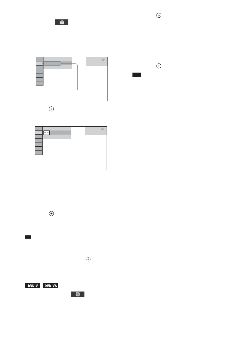
3 Press X/x to select [SET t], then
press .
Total time of the programmed tracks
PROGRAM 0: 00:00
ALL CLEAR
1. TRACK
2. TRACK
3. TRACK
4. TRACK
5. TRACK
6. TRACK
7. TRACK
– – – –
– –
– –
– –
– –
– –
– –
Tracks recorded on a disc
T
01
02
03
04
05
06
4 Press c.
The cursor moves to the track row [T] (in
this case, [01]).
PROGRAM 0: 00:00
ALL CLEAR
1. TRACK
2. TRACK
3. TRACK
4. TRACK
5. TRACK
6. TRACK
7. TRACK
US
38
– – – –
– –
– –
– –
– –
– –
– –
T
01
02
03
04
05
06

5 Select the track you want to program.
For example, select track [02].
Press X/x to select [02] under [T], then
press .
Selected track
PROGRAM 0: 03:51
ALL CLEAR
1. TRACK
2. TRACK
3. TRACK
4. TRACK
5. TRACK
6. TRACK
7. TRACK
Total time of the programmed tracks
02 – –
– –
– –
– –
– –
– –
– –
T
01
02
03
04
05
06
6 To program other tracks, repeat Steps
4 to 5.
The programmed tracks are displayed in the
selected order.
7 Press H to start Program Play.
Program Play starts.
When the program ends, you can restart the
same program again by pressing H.
To return to normal play
Press CLEAR while the display for the program
setting is not displayed on the TV screen, or
select [OFF] in Step 3. To play the same
program again, select [ON] in Step 3 and press
.
To turn off the Control Menu
display
Press DISPLAY repeatedly until the Control
Menu display is turned off.
To change or cancel a program
1 Follow Steps 1 to 3 of “Creating your
own program.”
2 Press X/x to select the program
number of the track you want to
change or cancel.
If you want to delete the track from the
program, press CLEAR.
3 Follow Step 5 for new programming.
To cancel a program, select [--] under [T],
then press .
To cancel all of the tracks in the
programmed order
1 Follow Steps 1 to 3 of “Creating your
own program.”
2 Press X and select [ALL CLEAR].
3 Press .
Note
• When you press CLEAR to return to normal play,
Shuffle Play and Repeat Play are also canceled.
Playing in random order
(Shuffle Play)
You can play the contents on a disc in random
order. Subsequent Shuffle Play may produce a
different playing order.
Note
• The same song may be played repeatedly when you
are playing MP3 files.
1 Press DISPLAY during playback.
The Control Menu display appears on the
TV screen.
2 Press X/x to select [SHUFFLE],
then press .
The options for [SHUFFLE] appear.
3 Press X/x to select the item to be
shuffled.
x VIDEO CD/Super Audio CD/CD
•[OFF]: Off.
• [TRACK]: You can shuffle tracks on the
disc.
x During Program Play
•[OFF]: Off.
• [ON]: You can shuffle tracks selected in
Program Play.
x DATA CD/DATA DVD
•[OFF]: Off.
• [ON (MUSIC)]: You can shuffle MP3
files in the folder on the current disc.
When no folder is selected, the first folder
will play in random order.
Disc
39
US

4 Press .
Shuffle Play starts.
To return to normal play
Press CLEAR, or select [OFF] in Step 3.
To turn off the Control Menu
display
Press DISPLAY repeatedly until the Control
Menu display is turned off.
Note
• You cannot use Shuffle Play with a VIDEO CD or
Super VCD with PBC playback.
• When you press CLEAR to return to normal play,
Program Play and Repeat Play are also canceled.
• [TRACK]: You can repeat the current
track.
x DATA CD/DATA DVD
• [OFF]: Off.
• [DISC]: You can repeat all of the folders
on the disc.
• [FOLDER]: You can repeat the current
folder.
• [TRACK] (MP3 files only): You can
repeat the current file.
4 Press .
The item is selected.
To return to normal play
Press CLEAR, or select [OFF] in Step 3.
Playing repeatedly
(Repeat Play)
You can play the contents on a disc repeatedly.
You can use a combination of Shuffle Play or
Program Play modes.
1 Press DISPLAY during playback.
The Control Menu display appears on the
TV screen.
2 Press X/x to select [REPEAT],
then press .
The options for [REPEAT] appear.
3 Press X/x to select the item to be
repeated.
x DVD VIDEO/DVD-VR
•[OFF]: Off.
• [DISC]: You can repeat all of the titles on
the disc.
• [TITLE]: You can repeat the current title
on a disc.
• [CHAPTER]: You can repeat the current
chapter on a disc.
x VIDEO CD/Super Audio CD/CD
•[OFF]: Off.
• [DISC]: You can repeat all of the tracks
on the disc.
To turn off the Control Menu
display
Press DISPLAY repeatedly until the Control
Menu display is turned off.
Note
• You cannot use Repeat Play with a VIDEO CD or
Super VCD with PBC playback.
• When the system is playing a DATA CD/DATA
DVD which contains MP3 files and JPEG image
files, and their playing time is not the same, the audio
sound will not match the image.
• When you press CLEAR to return to normal play,
Program Play and Shuffle Play are also canceled.
40
US

Searching/Selecting Disc Contents
Selecting an original title or edited title on a DVD-VR
Using the DVD’s menu
A DVD is divided into many sections, which
make up a picture or music feature. These
sections are called “titles.” When you play a
DVD which contains several titles, you can
select the title you want using DVD TOP
MENU.
When you play a DVD that allows you to select
items such as the language for the subtitles and
the language for the sound, select these items
using DVD MENU.
1 Press DVD TOP MENU or DVD MENU.
The disc’s menu appears on the TV screen.
The contents of the menu vary depending
on the disc.
2 Press C/X/x/c or the number buttons to
select the item you want to play or
change.
3 Press .
To display the DVD’s menu on the
Control Menu display
1 Press DISPLAY during playback.
The Control Menu display appears on the
TV screen.
2 Press X/x to select [DISC
MENU], then press .
The options for [DISC MENU] appear.
3 Press X/x to select [MENU] or [TOP
MENU].
4 Press .
To turn off the Control Menu
display
Press DISPLAY repeatedly until the Control
Menu display is turned off.
This function is only available for DVD-VRs
with a playlist created.
1 Press DISPLAY while the system is
in stop mode.
The Control Menu display appears on the
TV screen.
2 Press X/x to select [ORIGINAL/
PLAY LIST], then press .
The options for [ORIGINAL/PLAY LIST]
appear.
3 Press X/x to select a setting.
• [PLAY LIST]: You can play the titles in
the order of the existing playlist.
• [ORIGINAL]: You can play the titles
originally recorded.
4 Press .
Searching for a title/chapter/ track/scene, etc.
You can search a DVD VIDEO/DVD-VR by
title or chapter, and you can search a VIDEO
CD/Super Audio CD/CD/DATA CD/DATA
DVD by track, index, or scene. For a DATA CD/
DATA DVD, you can search by folder or file.
As titles and tracks are assigned unique numbers
on the disc, you can select the desired title or
track by entering its number. Or, you can search
for a scene using the time code.
1 Press DISPLAY. (If [MEDIA] is set to
[MUSIC/PHOTO], press DISPLAY
twice.)
The Control Menu display appears on the
TV screen.
Disc
41
US
2 Press X/x to select the search method.
p
Example: [CHAPTER]
[** (**)] is selected (** refers to a number).
The number in parentheses indicates the
total number of titles, chapters, tracks,
indexes, scenes, folders, or files.
98( 99)
13( 99)
T 0: 03: 17
Selected row
DVD VIDEO
3 Press .
[** (**)] changes to [– – (**)].
98( 99)
13( 99)
T 0: 03: 17
DVD VIDEO
4 Press X/x or the number buttons to
select the desired number of the title,
chapter, track, index, scene, etc.
If you make a mistake, press CLEAR to
cancel the number.
5 Press .
The system starts playback from the
selected number.
Ti
• When the C ontrol Menu display is turned off, you can
search for a chapter (DVD VIDEO/DVD-R/DVDRW) or track (VIDEO CD/Super Audio CD/CD) by
pressing the number buttons and .
To search for a scene using the
time code
2 Press .
[T **:**:**] changes to [T --:--:--].
3 Input the time code using the number
buttons.
For example, to find a scene at 2 hours, 10
minutes, and 20 seconds after the
beginning: press 2, 1, 0, 2, 0 ([2:10:20]).
4 Press .
Note
• You cannot search for a scene on a DVD+RW using
the time code.
1 In Step 2, select [TIME].
[T **:**:**] (playing time of the current
title) is selected.
US
42

Playing MP3 Files/JPEG Image Files
You can play MP3 files or JPEG image files:
– which have the extension “.mp3” (MP3 file)
or “.jpg”/“.jpeg” (JPEG image file).
– which conform to the DCF* image file
format.
* “Design rule for Camera File system”: Image
standards for digital cameras regulated by Japan
Electronics and Information Technology Industries
Association (JEITA).
Note
• The system will play any files with the extension
“.mp3,” “.jpg,” or “.jpeg” even if they are not in MP3
or JPEG format. Playing these files may generate a
loud noise which could damage your speaker system.
• The system does not play back audio in MP3PRO
format.
• The system can recognize up to 200 folders, and will
not play any folders beyond the 200t h. (Depe nding on
the folder configuration, the number of folders that
can be recognized by the system may decrease.)
• The system can recognize up to 150 MP3 files/JPEG
image files in a folder.
• The system may take a longer time to play files when
progressing to the following folder or jumping to
other folders.
• The system ma y not play certain types of JPEG image
files (ex. a JPEG image file that is less than 8 (width)
× 8 (height)).
Selecting an MP3 file or folder
1 Press FUNCTION +/– repeatedly until
“DVD” appears in the front panel
display.
2 Load a DATA CD or DATA DVD.
After loading the disc, the list of folders
appears on the TV screen.
3 Press DISPLAY.
The Control Menu display appears on the
TV screen.
4 Press X/x to select [MEDIA],
then press .
The options for [MEDIA] appear.
5 When [MUSIC] is selected, press DVD
MENU. When other than [MUSIC] is
selected, press X/x to select [MUSIC],
then press .
A list of folders that contain MP3 files
appears.
The selected folder is highlighted in yellow.
FOLDER LIST
01 Let's Talk About Love (1985)
02 1st Album (1986)
03 In the Middle of Nowhere (1986)
04 Ready for Romance (1986)
05 In the Garden of Venus (1987)
06 Romantic Warriors (1987)
07 Back for Good (1988)
08 Alone (1999)
6 Press X/x to select a folder.
x To play MP3 files in a folder
Press H to start playing the selected
folder.
x To select an MP3 file
Press .
The list of files contained in the folder
appears.
TRACK LIST
03 In the Middle of Nowher...
01_Geronimo_s_Cadillac
02_Riding_On_A_White_Swan
03_Give_Me_Peace_On_Earth
04_Sweet_Little_Shella
05_Ten_Thousand_Lonely_Drums
06_Lonely_Tears_In_Chinatown
07_In_Shaire
Press X/x to select a file and press .
The system starts playing the selected file.
You can turn the file list off by pressing
DVD MENU. Pressing DVD MENU again
will display the folder list.
To go to the next or previous
page
Press / .
To stop playback
Press x.
Disc
43
US

To play the next or previous MP3
file
Press > to play the next MP3 file. Press .
twice to play the previous MP3 file.
When you press . once, you can go to the
beginning of the current MP3 file.
Note that you can select the next folder by
continuing to press > after the last file on the
current folder, but that you cannot return to the
previous folder by pressing .. To return to
the previous folder, select the folder from the
folder list.
To return to the previous display
Press O RETURN.
To turn on/off the display
Press DVD MENU.
Other operations
See “Other operations” (page 34).
Selecting a JPEG image file or folder
1 Press FUNCTION +/– repeatedly until
“DVD” appears in the front panel
display.
2 Load a DATA CD or DATA DVD.
After loading the disc, the list of folders
appears on the TV screen.
3 Press DISPLAY.
The Control Menu display appears on the
TV screen.
4 Press X/x to select [MEDIA],
then press .
The options for [MEDIA] appear.
5 When [PHOTO] is selected, press DVD
MENU. When other than [PHOTO] is
selected, press X/x to select [PHOTO],
then press .
A list of folders that contain JPEG files
appears.
The selected folder is highlighted in yellow.
FOLDER LIST
01 Happy birthday
02 Travelling 01
03 2003.08.20
04 Flowers
05 Travelling 02
06 Animals
07 2003.11.16
08 2003.12.03
6 Press X/x to select a folder.
x To go to the next or previous page
Press / .
x To play JPEG image files in a folder
Press H to start playing the selected
folder.
The JPEG images are played as a slide
show. You can change the interval of the
slide show (page 45), and add effects to the
slide show (page 46).
x To select a JPEG image file by
displaying the image browser
Press PICTURE NAVI.
Previews of JPEG image files in the folder
appear in 16 subscreens.
1234
5678
9101112
13 14 15 16
Press C/X/x/c to select the JPEG image
file you want to view, then press .
To return to the previous screen, press O
RETURN.
To play the next or previous JPEG
image file
Press c/C when the Control Menu display is not
displayed. Note that you can select the next
folder by continuing to press c after the last
image on the current folder, but that you cannot
return to the previous folder by pressing C. To
return to the previous folder, select the folder
from the folder list.
44
US

To rotate a JPEG image file
When a JPEG image file is displayed on the TV
screen, you can rotate the JPEG image file in 90
degree increments.
Press X/x while viewing a JPEG image file.
Press CLEAR to return to normal view.
Note
• You cannot rotate the JPEG image file when you set
[JPEG RESOLUTION] in [HDMI SETUP] to [(1920
× 1080i) HD ] or [(1920 × 1080i) HD] (page 53).
To stop playback
Press x.
To turn on/off the display
Press DVD MENU.
Other operations
See “Other operations” (page 34).
Playing a slide show with sound
You can play a slide show with sound by first
placing both MP3 files and JPEG image files in
the same folder on a DATA CD or DATA DVD.
1 Press FUNCTION +/– repeatedly until
“DVD” appears in the front panel
display.
2 Load a DATA CD or DATA DVD.
After loading the disc, the list of folders
appears on the TV screen.
3 Press DISPLAY.
The Control Menu display appears on the
TV screen.
4 Press X/x to select [MEDIA],
then press .
The options for [MEDIA] appear.
5 When [MUSIC/PHOTO] is selected,
press DVD MENU. When other than
[MUSIC/PHOTO] is selected, press X/x
to select [MUSIC/PHOTO], then press
.
The list of folders appears.
6 Press X/x to select the desired folder
and press H.
The system starts playing the selected
folder.
You can turn the folder list on/off by
pressing DVD MENU repeatedly.
Note
• If you play a large MP3 file and JPEG image file at
the same time, the sound may skip. Sony
recommends that you set the MP3 bit rate to 128 kbps
or lower when creating the file. If the sound still
skips, reduce the size of the JPEG image file.
Selecting the slide show duration of JPEG image files
1 Press DISPLAY. (If [MEDIA] is set to
[MUSIC/PHOTO], press DISPLAY
twice.)
The Control Menu display appears on the
TV screen.
2 Press X/x to select [INTERVAL],
then press .
The options for [INTERVAL] appear.
3 Press X/x to select a setting.
• [NORMAL]: You can set to the standard
duration.
• [FAST]: You can set the duration shorter
than [NORMAL].
• [SLOW 1]: You can set the duration
longer than [NORMAL].
• [SLOW 2]: You can set the duration
longer than [SLOW 1].
4 Press .
Note
• Some JPEG image files may take longer to display
than the option you selected. Especially progressive
JPEG image files or JPEG image files of 3,000,000
pixels or more.
Disc
45
US
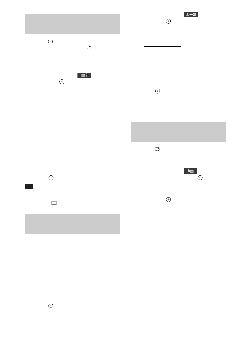
Selecting an effect for JPEG image files in the slide show
1 Press DISPLAY. (If [MEDIA] is set to
[MUSIC/PHOTO], press DISPLAY
twice.)
The Control Menu display appears on the
TV screen.
2 Press X/x to select [EFFECT],
then press .
The options for [EFFECT] appear.
3 Press X/x to select a setting.
• [MODE 1]: The JPEG image file sweeps
in from top to bottom.
• [MODE 2]: The JPEG image file stretches
out from left to right of the TV screen.
• [MODE 3]: The JPEG image file stretches
out from the center of the TV screen.
• [MODE 4]: The JPEG image files
randomly cycle through the effects.
• [MODE 5]: The next JPEG image file
slides over the previous image.
• [OFF]: Off.
4 Press .
Note
• The [EFFECT] setting is not effective when you set
[JPEG RESOLUTION] in [HDMI SETUP] to [(1920
× 1080i) HD ] or [(1920 × 1080i) HD] (page 53).
Selecting playback priority of the file type
You can select playback priority when mixed
media (MP3 files or JPEG image files) are in the
disc.
1 Press FUNCTION +/– repeatedly until
“DVD” appears in the front panel
display.
2 Load a DATA CD or DATA DVD.
After loading the disc, the list of folders
appears on the TV screen.
3 Press DISPLAY.
The Control Menu display appears on the
TV screen.
4 Press X/x to select [MEDIA],
then press .
The options for [MEDIA] appear.
5 Press X/x to select a setting.
• [MUSIC/PHOTO]: You can play both
JPEG image files and MP3 files in the
same folder as a slide show.
• [MUSIC]: MP3 file playback has priority.
• [PHOTO]: JPEG image file playback has
priority. You can play JPEG image files as
a slide show.
6 Press .
For details of the playback priority of file
types under the [MEDIA] setting, see
“Playback priority of file types” (page 92).
Displaying a list of MP3 files/ JPEG image files
1 Press DISPLAY during playback.
The Control Menu display appears on the
TV screen.
2 Press X/x to select
[BROWSING], then press .
The options for [BROWSING] appear.
3 Press X/x to select the desired list,
then press .
• [FOLDER LIST]: The list of folders
appears. Follow Step 6 of “Selecting an
MP3 file or folder” (page 43) or
“Selecting a JPEG image file or folder”
(page 44).
• [PICTURE LIST] (JPEG image files
only): Previews of JPEG image files in the
folder appear in 16 subscreens. Follow
Step 6 of “Selecting a JPEG image file or
folder” (page 44).
46
US
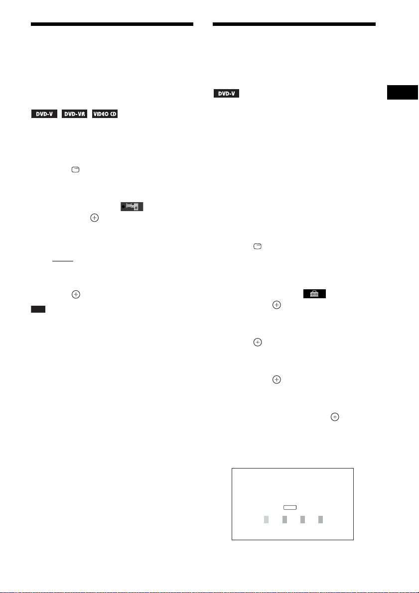
Adjusting the Delay
Restricting Playback of
Between the Picture and
Sound
[A/V SYNC]
When the sound does not match the pictures on
the TV screen, you can adjust the delay between
the picture and sound.
1 Press DISPLAY.
The Control Menu display appears on the
TV screen.
2 Press X/x to select [A/V SYNC],
then press .
The options for [A/V SYNC] appear.
3 Press X/x to select a setting.
•[OFF]: Off.
• [ON]: You can adjust the delay between
picture and sound.
4 Press .
Note
• Depending on th e input st ream, [A/V SYNC] may not
be effective.
the Disc
[PARENTAL CONTROL]
Disc
The [PARENTAL CONTROL] function allows
you to restrict playback of DVDs that have
ratings. Scenes may be blocked or replaced with
different scenes.
You can set the playback restriction by
registering a password. When you set the
[PARENTAL CONTROL] function to on, you
need to enter the password to play restricted
discs.
1 Press FUNCTION +/– repeatedly until
“DVD” appears in the front panel
display.
2 Press DISPLAY while the system is
in stop mode.
The Control Menu display appears on the
TV screen.
3 Press X/x to select [SETUP],
then press .
The options for [SETUP] appear.
4 Press X/x to select [CUSTOM], then
press .
The Setup Display appears.
5 Press X/x to select [SYSTEM SETUP],
then press .
The options for [SYSTEM SETUP] appear.
6 Press X/x to select [PARENTAL
CONTROL t], then press .
x If you have not entered a password
The display for registering a new password
appears.
PARENTAL CONTROL
Enter a new 4-digit password,
ENTER
then press
.
47
US

Enter a 4-digit password using the number
p
buttons, then press .
The display for confirming the password
appears.
x When you have already registered a
password
The display for entering the password
appears.
7 Enter or re-enter your 4-digit password
using the number buttons, then press
.
The display for setting the playback
limitation level appears.
PARENTAL CONTROL
LEVEL:
STANDARD:
CHANGE PASSWORD:
OFF
USA
8 Press X/x to select [STANDARD], then
press .
The selection items for [STANDARD] are
displayed.
9 Press X/x to select a geographic area
as the playback limitation level, then
press .
The area is selected.
When you select [OTHERS t], select and
enter a standard code from “Parental
Control Area Code List” (page 93) using
the number buttons.
10 Press X/x to select [LEVEL], then press
.
The selection items for [LEVEL] are
displayed.
11 Press X/x to select the desired level,
then press .
[PARENTAL CONTROL] setting is
complete.
The lower the value, the stricter the
limitation.
To turn off the [PARENTAL
CONTROL] function
Set [LEVEL] to [OFF] in Step 11.
To play a disc for which
[PARENTAL CONTROL] is set
1 Load the disc and press H.
The display for entering your password
appears.
2 Enter your 4-digit password using the
number buttons, then press .
The system starts playback.
Ti
• If you forget your password, remove the disc and
repeat Steps 1 to 6 of “Restricting Playback of the
Disc” (page 47). When you are asked to enter your
password, enter “199703” using the number buttons,
then press . The dis play will ask you to enter a new
4-digit password. After you enter a new 4-digit
password, replace the disc in the unit and press H.
When the display for entering your password appears,
enter your new password.
Changing the password
1 Press FUNCTION +/– repeatedly until
“DVD” appears in the front panel
display.
2 Press DISPLAY while the system is
in stop mode.
The Control Menu display appears on the
TV screen.
3 Press X/x to select [SETUP],
then press .
The options for [SETUP] appear.
4 Press X/x to select [CUSTOM], then
press .
The Setup Display appears.
5 Press X/x to select [SYSTEM SETUP],
then press .
The options for [SYSTEM SETUP] appear.
6 Press X/x to select [PARENTAL
CONTROL t], then press .
The display for entering the password
appears.
US
48

7 Enter your 4-digit password using the
number buttons, then press .
8 Press X/x to select [CHANGE
PASSWORD t], then press .
9 Enter a new 4-digit password using the
number buttons, then press .
10 To confirm your password, re-enter it
using the number buttons, then press
.
If you make a mistake entering
your password
Press C before you press , then input the
correct number.
Changing the System Settings by Using the Setup Display
You can make various adjustments to items such
as picture and sound.
Displayed items vary depending on the area.
Note
• Playback settings stored in the disc take priority over
the Setup Display settings and not all the functions
described may work.
1 Press FUNCTION +/– repeatedly until
“DVD” appears in the front panel
display.
2 Press DISPLAY while the system is
in stop mode.
The Control Menu display appears on the
TV screen.
3 Press X/x to select [SETUP],
then press .
The options for [SETUP] appear.
4 Press X/x to select [CUSTOM], then
press .
The Setup Display appears.
5 Press X/x to select the setup item, then
press .
• [LANGUAGE SETUP] (page 50)
• [VIDEO SETUP] (page 50)
• [HDMI SETUP] (page 52)
• [AUDIO SETUP] (page 53)
• [SYSTEM SETUP] (page 54)
• [SPEAKER SETUP] (page 54)
Disc
Example: [VIDEO SETUP]
Selected item
VIDEO SETUP
TV TYPE:
PROGRESSIVE
4:3 OUTPUT:
BLACK LEVEL:
BLACK LEVEL
PAUSE MODE:
(COMPONENT OUT)
(COMPONENT OUT)
Setup items
16:9
:
OFF
FULL
ON
:
OFF
AUTO
US
49

6 Press X/x to select an item, then press
p
.
The options for the selected item appear.
Example: [TV TYPE]
VIDEO SETUP
TV TYPE:
PROGRESSIVE
4:3 OUTPUT:
BLACK LEVEL:
BLACK LEVEL
PAUSE MODE:
(COMPONENT OUT)
4:3 LETTER BOX
(COMPONENT OUT)
16:9
16:9
:
OFF
FULL
AUTO
4:3 PAN SCAN
:
OFF
AUTO
Options
7 Press X/x to select a setting, then
press .
The setting is selected and setup is
complete.
Example: [4:3 LETTER BOX]
VIDEO SETUP
TV TYPE:
PROGRESSIVE
4:3 OUTPUT:
BLACK LEVEL:
BLACK LEVEL
PAUSE MODE:
To reset all of the [SETUP]
settings
To reset all of the [SETUP] settings, see
“Returning the [SETUP] settings to the default”
(page 77).
4:3 LETTER BOX
(COMPONENT OUT)
(COMPONENT OUT)
Selected setting
:
:
OFF
FULL
ON
OFF
AUTO
x [OSD] (On-Screen Display)
You can switch the display language on the TV
screen.
x [MENU] (DVD VIDEO only)
You can switch the language for the disc’s
menu.
x [AUDIO] (DVD VIDEO only)
You can switch the language of the sound track.
When you select [ORIGINAL], the language
given priority on the disc is selected.
x [SUBTITLE] (DVD VIDEO only)
You can switch the language of the subtitles
recorded on the DVD VIDEO.
When you select [AUDIO FOLLOW], the
language for the subtitles changes according to
the language you selected for the sound track.
Note
• When you select a language in [MENU], [AUDIO],
or [SUBTITLE] that is not recorded on the DVD
VIDEO, one of the recorded languages will be
automatically selected (depending on the disc, the
language may not be selected automatically).
Ti
• If you select [OTHERS t] in [MENU], [AUDIO],
and [SUBTITLE], select and enter a language code
from “Language Code List” (page 93) using the
number buttons.
Setting the display or sound track language
[LANGUAGE SETUP]
Settings for the display
[VIDEO SETUP]
Select settings according to the TV to be
connected.
Set various languages for the on-screen display
or sound track.
LANGUAGE SETUP
OSD:
MENU:
AUDIO:
SUBTITLE:
US
50
ENGLISH
ENGLISH
ORIGINAL
AUDIO FOLLOW
VIDEO SETUP
TV TYPE:
PROGRESSIVE
4:3 OUTPUT:
BLACK LEVEL:
BLACK LEVEL
PAUSE MODE:
(COMPONENT OUT)
(COMPONENT OUT)
:
:
16:9
OFF
FULL
ON
OFF
AUTO

x [TV TYPE]
You can select the aspect ratio of the connected
TV.
: Select this when you connect a wide-
[16:9]
screen TV or a TV with a wide mode function.
[4:3 LETTER BOX]: Select this when you
connect a 4:3 standard TV. The system displays
a wide picture with bands on the upper and
lower portions of the TV screen.
The system outputs a progressive signal for
5 seconds. Check that the screen is
displayed correctly.
3 Press C/c to select [YES], then press
.
The system outputs a progressive signal. If
you select [NO], the system will not output
a progressive signal.
Note
• [PROGRESSIVE (COMPONENT OUT)] is
effective only when you connect the unit and TV with
a component video cable (page 20).
x [4:3 OUTPUT]
When you use a 16:9 aspect ratio TV, you can
adjust the aspect ratio to watch 4:3 aspect ratio
signals. If you can change the aspect ratio on
your TV, change the setting on your TV, not the
system.
Disc
[4:3 PAN SCAN]: Select this when you connect
a 4:3 standard TV. The system automatically
displays a wide picture on the entire screen and
cuts off the portions that do not fit.
Note
• Depending on the DVD, [4:3 LETTER BOX] may be
selected automa tically instead of [4:3 PAN SC AN] or
vice versa.
x [PROGRESSIVE (COMPONENT OUT)]
You can set the progressive signal that is output
from the COMPONENT VIDEO OUT jacks to
on/off. For details, see “Does your TV accept
progressive signals?” (page 28).
: The system outputs interlace signals.
[OFF]
[ON]: The system outputs progressive signals.
When you select [ON], follow the Steps below.
1 Select [ON], then press .
The confirmation display appears.
2 Press C/c to select [START], then
press .
[FULL]: Select this when you can change the
aspect ratio on your TV.
[NORMAL]: Select this when you cannot
change the aspect ratio on your TV. A 16:9
aspect ratio signal with black bands on left and
right sides of the image appears.
16:9 aspect ratio TV
Note
• [4:3 OUTPUT] is effective only when you set [TV
TYPE] in [VIDEO SETUP] to [16:9].
x [BLACK LEVEL]
You can select the black level (setup level) for
the video signals output from the jacks other
than COMPONENT VIDEO OUT/HDMI OUT.
[ON]: The standard level.
[OFF]: You can lower the standard black level.
Use this when the picture becomes too white.
x [BLACK LEVEL (COMPONENT OUT)]
You can select the black level (setup level) for
the video signals output from the
COMPONENT VIDEO OUT jacks.
51
US

You cannot select this and the setting is not
effective when the system outputs a progressive
signal.
[OFF]: You can set the black level of the output
signal to the standard level.
[ON]: You can raise the standard black level.
Use this when the picture becomes too black.
x [PAUSE MODE] (DVD VIDEO/DVD-R/
DVD-RW only)
You can select the picture in pause mode.
[AUTO]: The picture, including subjects that
move dynamically, is output with no jitter. This
setting is for normal usage.
[FRAME]: The picture, including subjects that
do not move dynamically, is output in high
resolution.
Settings for HDMI
[HDMI SETUP]
** Depending on the area, [720 × 480/576p] may
appear.
x [CONTROL FOR HDMI]
You can set the [CONTROL FOR HDMI]
function to on/off. This function is available
when you connect the system and TV with an
HDMI cable. For details, see “Using the Control
for HDMI Function for “BRAVIA” Sync”
(page 60).
: On. You can operate mutually between
[ON]
components that are connected with an HDMI
cable.
[OFF]: Off.
x [VOLUME LIMIT]
If you change the output method of the TV to the
system speakers via the TV menu (or by
pressing THEAT ER), the System Audio Contro l
(page 61) is activated and loud sound may be
output depending on the volume level of the
system. You can prevent this by limiting the
maximum level of the volume.
HDMI SETUP
HDMI RESOLUTION:
CONTROL FOR HDMI:
VOLUME LIMIT:
YCBCR/RGB(HDMI):
AUDIO(HDMI):
JPEG RESOLUTION:
x [HDMI RESOLUTION]
You can select the type of video signal that is
output from the HDMI OUT jack. For details,
see “To select the type of video signal output
from the HDMI OUT jack” (page 28).
[AUTO (1920
× 1080p)]: The system outputs
the optimal video signal for the connected TV.
[1920
× 1080i]: The system outputs 1920 ×
1080i* video signals.
[1280 × 720p]: The system outputs 1280 ×
720p* video signals.
[720 × 480p]**: The system outputs 720 ×
480p* video signals.
* i: interlace, p: progressive
US
52
AUTO
(1920x1080p)
ON
LEVEL2
YC
BCR
OFF
SD
[LEVEL3]: Maximum volume level is set to 10.
[LEVEL2]
: Maximum volume level is set to 15.
[LEVEL1]: Maximum volume level is set to 20.
[OFF]: Off.
Note
• This function is available only when [CONTROL
FOR HDMI] is set to [ON].
x [YCBCR/RGB (HDMI)]
You can select the type of HDMI signal output
from the HDMI OUT jack.
[
YCBCR]: The system outputs YCBCR signals.
[RGB]: The system outputs RGB signals.
Note
• If the playback picture becomes distorted, set
BCR] to [RGB].
[YC
• If the HDMI OUT jack is connected to a component
with a DVI jack, [RGB] signals will be automatically
output even when you select [YC
BCR].

x [AUDIO (HDMI)]
You can select the audio output status from the
HDMI OUT jack.
: The system does not output sound from
[OFF]
the HDMI OUT jack.
[ON]: The system outputs audio signals by
converting Dolby Digital, DTS, or 96 kHz/24bit PCM signals to 48 kHz/16-bit PCM.
Note
• When you connect the unit and TV with an HDMI
cable and [ON] is selected, [AUDIO DRC], [A/V
SYNC], DYNAMIC BASS, “DEC. MODE,” and
sound mode are not applied to the sound that is output
from the TV.
• When you set the function to other than “DVD,” the
system does not output the sound from the HDMI
OUT jack even if you set [AUDIO (HDMI)] to [ON].
x [JPEG RESOLUTION]
You can select the resolution of JPEG image
files output from the HDMI OUT jack.
[SD
]: The system outputs standard
resolution with a black frame.
[HD ]: The system outputs HD resolution
with a black frame.
[HD]: The system outputs the HD resolution
without a black frame.
[(1920 × 1080i) HD ]: The system outputs
full size HD resolution with a black frame.
[(1920 × 1080i) HD]: The system outputs full
size HD resolution without a black frame.
Note
• [JPEG RESOLUTION] is effective only when you
set [TV TYPE] in [VIDEO SETUP] to [16:9], and
you set [HDMI RESOLUTION] in [HDMI SETUP]
to other than [720 × 480p] or [720 × 480/576p].
• You can select [(1920 × 1080i) HD ] or [(1920 ×
1080i) HD] only when you set [HDMI
RESOLUTION] in [HDMI SETUP] to [1920 ×
1080i].
• The HDMI signal will stop momentarily when the
system is loading or unloading a DATA CD or DATA
DVD.
Settings for the audio
[AUDIO SETUP]
AUDIO SETUP
SPEAKER FORMATION:
AUTO CALIBRATION:
AUDIO DRC:
TRACK SELECTION:
x [SPEAKER FORMATION]
You can select the position of the speakers for
better surround sound. For details, see “Getting
Optimal Surround Sound for a Room”
(page 69).
x [AUTO CALIBRATION]
You can calibrate the appropriate settings
automatically. For details, see “Calibrating the
Appropriate Settings Automatically” (page 70).
x [AUDIO DRC] (DVD VIDEO only)
You can compress the dynamic range of the
sound track. [AUDIO DRC] is useful for
watching movies at low volume late at night.
[OFF]: No compression of dynamic range.
[STANDARD]: The system reproduces the
sound track with the kind of dynamic range that
the recording engineer intended.
[MAX]: The system compresses dynamic range
fully.
Note
• [AUDIO DRC] works only for Dolby Digital.
x [TRACK SELECTION] (DVD VIDEO only)
You can give the sound track which contains the
highest number of channels priority when you
play a DVD VIDEO on which multiple audio
formats (PCM, DTS, Dolby Digital, or MPEG
audio) are recorded.
OFF
OFF
Disc
[OFF]: Off.
[AUTO]: The system selects the sound track
automatically according to the priority.
53
US

Note
• When you set the item to [AUTO], the language may
change. The [TRACK SELECTION] setting has
higher priority than the [AUDIO] settings in
[LANGUAGE SETUP] (page 50). (Depending on
the disc, this function may not work.)
• If PCM, DTS, Dolby Digital sound, and MPEG audio
have the same number of channels, the system selects
PCM, DTS, Dolby Digital sound, and MP EG audio in
this order.
Other Settings
[SYSTEM SETUP]
SYSTEM SETUP
SCREEN SAVER:
BACKGROUND:
PARENTAL CONTROL:
MULTI-DISC RESUME:
RESET:
JACKET PICTURE
ON
ON
x [PARENTAL CONTROL]
You can set the playback restrictions. For
details, see “Restricting Playback of the Disc”
(page 47).
x [MULTI-DISC RESUME] (DVD VIDEO/
VIDEO CD only)
You can set the [MULTI-DISC RESUME]
function to on/off.
[ON]
: The system stores the resume points in
memory for up to 10 discs.
[OFF]: The system does not store the resume
points in memory. Playback restarts at the
resume point only for the current disc in the unit.
x [RESET]
You can return the [SET UP] settings other than
[PARENTAL CONTROL] to the default
settings. For details, see “Returning the
[SETUP] settings to the default” (page 77).
x [SCREEN SAVER]
You can reduce the
(ghosting). Press any button (e.g.,
damage to the display device
H
) to cancel
the screen saver.
: The screen saver image appears if you do
[ON]
not operate the system for about 15 minutes.
[OFF]: Off.
x [BACKGROUND]
You can select the background color or picture
on the TV screen.
[JACKET PICTURE]
: The jacket picture (still
picture) appears, but only when the jacket
picture is already recorded on the disc (CDEXTRA, etc.). If the disc does not contain a
jacket picture, the [GRAPHICS] picture
appears.
[GRAPHICS]: A preset picture stored in the
system appears.
[BLUE]: The background is blue.
[BLACK]: The background is black.
Settings for the speakers
[SPEAKER SETUP]
To obtain the best possible surround sound, set
connection of the speakers and their distance
from your listening position. Then use the test
tone to adjust the level and the balance of the
speakers to the same level.
SPEAKER SETUP
CONNECTION:
DISTANCE(FRONT)
DISTANCE(SURROUND):
LEVEL(FRONT):
LEVEL(SURROUND):
TEST TONE
FRONT:
CENTER:
SURROUND:
SUBWOOFER:
x [CONNECTION]
If you do not connect center or surround
speakers, set the parameters for [CENTER] and
[SURROUND]. Since the front speaker and
subwoofer settings are fixed, you cannot change
them.
[FRONT]
[YES]
:
YES
YES
YES
YES
54
US

[CENTER]
[YES]: Normally select this.
[NONE]: Select this if no center speaker is used.
[SURROUND]
[YES]: Normally select this.
[NONE]: Select this if no surround speakers are
used.
[SUBWOOFER]
[YES]
Note
• When you change the [CONNECTION] setting, the
[STANDARD] of [SPEAKER FORMATION]
setting remains the same, but the other settings of
[SPEAKER FORMATION] return to
[STANDARD].
x [DISTANCE (FRONT)]
When you move the front speakers and center
speaker, be sure to set the parameters of the
distance (A) from the listening position to the
speakers.
You can set the parameters from 1.0 to 7.0
1)
meters
(3 to 23 ft) for the front speakers, from
2)
0.0 to 7.0 meters
(0 to 23 ft) for the center
speaker.
A
[L/R] 3.0 m/10 ft
distance.
[CENTER] 3.0 m/10 ft
3)
: Set the front speaker
3)4)
: Set the center speaker
distance (up to 1.6 meters (5 ft) closer to the
front speakers).
1)
0.9 to 6.9 meters for North American models.
2)
0.0 to 6.9 meters for North American models.
3)
When you perform the Quick Setup (page 26), the
default settings are changed.
4)
This item appears when you set [CENTER] to [YES]
in the [CONNECTION] setting.
x [DISTANCE (SURROUND)]
When you move the surround speakers, be sure
to set the parameters of the distance (B) from
the listening position to the speakers.
You can set the parameters from 0.0 to 7.0
meters1) (0 to 23 ft).
B
[L/R] 3.0 m/10 ft
2)3)
: Set the surround speaker
distance (up to 5.0 meters (16 ft) closer to the
front speakers).
1)
0.0 to 6.9 meters for North American models.
2)
When you perform the Quick Setup (page 26), the
default settings are changed.
3)
This item appears when you set [SURROUND] to
[YES] in the [CONNECTION] setting.
Note
• If all front and surround speakers are not placed at an
equal distance from your listening position, set the
distance according to the closest speaker.
• Do not place the surround speakers farther away from
your listening position than the front speakers.
• Depending on the input stream, the [DISTANCE]
setting may not be effective.
x [LEVEL (FRONT)]
You can adjust the sound level of the front
speakers, center speaker, and subwoofer. You
can set the parameters from –6.0 dB to 0 dB for
[L/R], and from –6.0 dB to +6.0 dB for
[CENTER] and [SUBWOOFER]. Be sure to set
[TEST TONE] to [ON] for easy adjustment.
[L/R] 0.0 dB
: Set the front speaker level.
Disc
55
US

[CENTER] 0.0 dB*: Set the center speaker
p
level.
[SUBWOOFER] +2.0 dB: Set the subwoofer
level.
* This item appears when you set [CENTER] to
[YES] in the [CONNECTION] setting.
x [LEVEL (SURROUND)]
You can adjust the sound level of the surround
speakers. You can set the parameter from –6.0
dB to +6.0 dB. Be sure to set [TEST TONE] to
[ON] for easy adjustment.
[L/R] 0.0 dB
* This item appears when you set [SURROUND] to
[YES] in the [CONNECTION] setting.
x [TEST TONE]
The speakers will emit a test tone to adjust
[LEVEL (FRONT)] and [LEVEL
(SURROUND)].
[OFF]: The test tone is not emitted from the
speakers.
[ON]: The test tone is emitted from each speaker
in sequence while adjusting the level. When you
select one of the [SPEAKER SETUP] items, the
test tone is emitted from each speaker in
sequence.
Adjust the sound level as follows.
*: Set the surround speaker level.
1 Set the [TEST TONE] to [ON].
2 Press C/X/x/c repeatedly to select the
desired speaker and the level.
3 Press .
4 Repeat Steps 1 to 3.
5 Press C/X/x/c repeatedly to set [TEST
TONE] to [OFF] after adjusting the
speaker level.
Ti
• To adjust the volume of all the speakers at one time,
turn the VOLUME control on the unit, or press
VOLUME +/– on the remote.
• To return to the default setting when changing a
setting, select the item, then press CLEAR. Note that
only the [CONNECTION] setting does not return to
the default setting.
US
56

p
Tuner
Presetting Radio Stations
You can preset 20 FM stations. Before tuning,
make sure to turn down the volume to minimum.
Current station
Current band and preset number
FM
FM 10 : 88.00 MHz
SONY RADIO
Station name
1 Press FUNCTION +/– repeatedly until
“TUNER FM” appears in the front panel
display.
2 Press and hold TUNING +/– until the
auto scanning starts.
Scanning stops when the system tunes in a
station. “TUNED” and “ST” (stereo
program) appear in the front panel display.
3 Press SYSTEM MENU.
4 Press X/x repeatedly until “MEMORY”
appears in the front panel display.
5 Press or c.
A preset number appears in the front panel
display.
7 Press .
“COMPLETE” appears in the front panel
display, and the station is stored.
8 Repeat Steps 2 to 7 to store other
stations.
9 Press SYSTEM MENU.
The system menu turns off.
To change the preset number
Select the desired preset number by pressing
PRESET +/– (page 58), then perform the
procedure from Step 3.
Tuner
6 Press X/x to select the preset number
you want.
Ti
• You can select the preset number directly by
pressing the number buttons.
57
US

Listening to the Radio
p
p
Preset radio stations in the system’s memory
first (see “Presetting Radio Stations” (page 57)).
1 Press FUNCTION +/– repeatedly until
“TUNER FM” appears in the front panel
display.
The last received station is tuned in.
2 Press PRESET +/– repeatedly to select
the preset station.
Each time you press the button, the system
tunes in one preset station.
Ti
• Y ou can select the preset station nu mber directly
by pressing the number buttons.
3 Adjust the volume by pressing
VOLUME +/–.
To turn off the radio
Press "/1.
To listen to non-preset radio
stations
Use manual or automatic tuning in Step 2.
For manual tuning, press TUNING +/–
repeatedly.
For automatic tuning, press and hold TUNING
+/–. The automatic tuning stops automatically
when the system receives the radio station. To
stop the automatic tuning manually, press
TUNING +/– or x.
To listen to radio stations when
you know the frequencies
Press D.TUNING in Step 2, press the number
buttons to select the frequencies, then press .
Ti
• To improve reception, reorient the connected
antennas (aerials).
If an FM program is noisy
If an FM program is noisy, you can select
monaural reception. There will be no stereo
effect, but reception will improve.
1 Press SYSTEM MENU.
2 Press X/x repeatedly until “FM MODE”
appears in the front panel display.
3 Press or c.
4 Press X/x to select “MONO.”
• “STEREO”: Stereo reception.
• “MONO”: Monaural reception.
5 Press .
The setting is made.
6 Press SYSTEM MENU.
The system menu turns off.
Naming preset stations
You can enter a name for preset stations. These
names (for example, “ABC”) appear in the front
panel display when a station is selected.
Only one name can be entered for each preset
station.
1 Press FUNCTION +/– repeatedly until
“TUNER FM” appears in the front panel
display.
The last received station is tuned in.
2 Press PRESET +/– repeatedly to select
the preset station you want to create an
index name for.
3 Press SYSTEM MENU.
4 Press X/x repeatedly until “NAME IN”
appears in the front panel display.
5 Press or c.
6 Create a name by using C/X/x/c.
Press X/x to select a character, then press c
to move the cursor to the next position.
You can input letters, numbers, and other
symbols for a radio station.
US
58

If you make a mistake
Press C/c repeatedly until the character to
be changed flashes, then press X/x to select
the desired character.
To erase the character, press C/c
repeatedly until the character to be erased
flashes, then press CLEAR.
7 Press .
“COMPLETE” appears in the front panel
display, and the station name is stored.
8 Press SYSTEM MENU.
The system menu turns off.
Viewing the station name or frequency in the front panel display
When the system is set to “TUNER FM,” you
can check the frequency using the front panel
display.
Press DISPLAY.
Each time you press DISPLAY, the display
changes:
1 t 2 t .... t 1 t ....
When the station name is set
1 Station name
Ex. “SONY RADIO”
2 Frequency
Ex. “FM1 87.50”
3 The “FM MODE” setting
Ex. “STEREO”
When the station name is not set
1 Frequency
Ex. “FM1 87.50”
2 The “FM MODE” setting
Ex. “STEREO”
Tuner
59
US

Control for HDMI/External Audio Device
Using the Control for
HDMI Function for
Note
• Depending on the connected component, the Control
for HDMI function may not work. Refer to the
operating instructions supplied with the component.
• The Control for HDMI function may not work if you
connect a component other than a Sony component,
even if the component is compatible with the Control
for HDMI function.
“BRAVIA” Sync
This function is available on TVs with the
“BRAVIA” Sync function only.
By connecting Sony components that are
compatible with the Control for HDMI function
with an HDMI cable, operation is simplified as
below:
– Theater Mode (page 61)
– One-Touch Play (page 61)
– System Power Off (page 61)
– System Audio Control (page 61)
– Volume Limit (page 62)
– Language Follow (page 62)
Control for HDMI is a mutual control function
standard used by CEC (Consumer Electronics
Control) for HDMI (High-Definition
Multimedia Interface).
The Control for HDMI function will not work in
the following cases:
– When you connect this system to a
component which is not compatible with the
Control for HDMI function.
– A component does not have an HDMI jack.
There are convenient buttons on the system’s
remote for operating the TV, such as
THEATER, ONE-TOUCH PLAY, TV [/1. For
details, see “Controlling the TV with the
Supplied Remote” (page 71) and refer to the
operating instructions of the TV.
Preparing the Control for HDMI function
(Control for HDMI - Easy Setting)
The system is compatible with the Control for
HDMI - Easy Setting function. If the TV is
compatible with the Control for HDMI - Easy
Setting function, you can set the system’s
[CONTROL FOR HDMI] function
automatically by setting the TV. For details,
refer to the operating instructions of the TV.
If the TV is not compatible with the Control for
HDMI - Easy Setting function, set the Control
for HDMI function of the system and TV
manually.
1 Make sure that the system and the TV
are connected with an HDMI cable.
2 Turn on the TV and press [/1 to turn on
the system.
3 Switch the input selector on your TV so
that the signal from the system through
the HDMI input appears on the TV
screen.
4 Set the Control for HDMI function of the
system and TV.
For details of the system settings, see the
following Steps. For details of the setting of
the TV, refer to the operating instructions of
the TV (depending on the TV, the default
setting of the Control for HDMI function
may be set to off).
60
THEATER
BRAVIA Sync
ONE-TOUCH
PLAY
TV
To set the [CONTROL FOR HDMI]
function to on/off
1 Press FUNCTION +/– repeatedly until
“DVD” appears in the front panel
display.
US

2 Press DISPLAY while the system is
in stop mode.
The Control Menu display appears on the
TV screen.
3 Press X/x to select [SETUP],
then press .
The options for [SETUP] appear.
4 Press X/x to select [CUSTOM], then
press .
The Setup Display appears.
5 Press X/x to select [HDMI SETUP], then
press .
The options for [HDMI SETUP] appear.
6 Press X/x to select [CONTROL FOR
HDMI], then press .
7 Press X/x to select the setting, then
press .
•[ON]: On.
• [OFF]: Off.
Using the Theater Mode
(Theater Mode)
If your TV is compatible with the Theater Mode,
you can enjoy optimal image and sound quality
suited for movies, and sound is output from the
system’s speakers automatically by pressing
THEATER.
This system TV
Turns on. (If not already
turned on.)
r
Switches to “DVD”
function.
r
Starts playing th e disc and
outputs the sound.
Turns on. (If not already
turned on.)
r
Switches to HDMI input.
r
Minimizes sound level.
(System Audio Control)
Turning the system off in sync with the TV
(System Power Off)
When you turn the TV off by using the POWER
button on the TV’s remote or TV [/1 on the
system’s remote, the system turns off
automatically.
Note
• Before using the System Power Off function, set the
function for TV power. For details, refer to the
operating instructions of the TV.
• Depending on the status of the system (ex. while
using other than “DVD” or “TV/VIDEO” functions,
or playing a CD), the system may not turn off
automatically.
Enjoying TV sound from the speakers by this system
Control for HDMI/External Audio Device
Watching a DVD by a single button press
(One-Touch Play)
By only pressing ONE-TOUCH PLAY, the TV
turns on, the TV is set for DVD input mode, and
the system starts playing a disc automatically.
Note
• One-Touch Play does not work when you press H.
The system and TV work as follows (e.g.):
(System Audio Control)
You can enjoy TV sound via this system easily.
To use this function, connect the system and the
TV with an audio cord and an HDMI cable
(pages 20, 21).
Depending on the TV, when you set the system
to the “TV/VIDEO” function, the System Audio
Control function is activated. TV sound is output
from the system speakers, and the volume of the
TV speakers is minimized automatically.
You can use the System Audio Control function
as follows:
• While you are watching the TV and the
function of the system is switched to “TV/
61
US

VIDEO,” TV sound is output from the system
p
speakers automatically.
• While you are watching the TV and the
function of the system is switched to “DVD,”
sound of the “DVD” function is output from
the system speakers; TV sound is not output
via the TV speakers.
• You can control the system’s volume by the
remote of the TV.
• If you turn the system off or set the function of
the system to other than “TV/VIDEO” or
“DVD,” TV sound is output from the TV
speakers.
You can also operate the System Audio Control
function via the TV menu. For details, refer to
the operating instructions of the TV.
Note
• While the TV is in PAP (picture and picture) mode,
the System Audio Control function will not work.
When the TV exits PAP mode, the output method of
the TV returns to the one before PAP mode.
Ti
• You can connect the system and the TV audio
digitally. For details, see page 21.
Setting the Maximum Volume Level of the System
(Volume Limit)
If you change the output method of the TV to the
system speakers via the TV menu (or by
pressing THEATER), loud sound may be output
depending on the volume level of the system.
You can prevent this by limiting the maximum
level of the volume. For details, see “[VOLUME
LIMIT]” (page 52).
Changing the language for the on-screen display of the TV
(Language Follow)
When you change the language for the on-screen
display of the TV, the system’s on-screen
display language is also changed. However,
when the system’s on-screen display is
displayed, this function does not work.
Using the DIGITAL MEDIA PORT Adapter
The DIGITAL MEDIA PORT (DMPORT)
adapter is for enjoying sound from a portable
audio source or computer. By connecting a
DIGITAL MEDIA PORT adapter, you can
enjoy sound from the connected component on
the system.
Available DIGITAL MEDIA PORT adapters
vary in each area.
For details on connecting the DIGITAL MEDIA
PORT adapter, see page 22.
Note
• Do not connect an adapter other than the DIGITAL
MEDIA PORT adapter.
• Do not connect or disconnect the DIGITAL MEDIA
PORT adapter to/from the unit while the system is
turned on.
• When you use the system and the Bluetooth Wireless
Audio Adapter (such as TDM-BT1, not supplied) at
the same time, transmission distance between the
Bluetooth transmitter and Bluetooth Wireless Audio
Adapter may be reduced. In this case, place the
Bluetooth transmitter as far as possible from the
system, or move the Bluetooth Wireless Audio
Adapter closer to the Bluetooth transmitter.
• When you use the system and the Wireless Network
Audio Adapter (such as TDM-NC1, not supplied) at
the same time, place the Wireless Network Audio
Adapter as far as possible from the system.
Playing the connected component on the system
1 Press FUNCTION +/– repeatedly until
“DMPORT” appears in the front panel
display.
2 Start playback of the connected
component.
The sound and images from the connected
component are played on the system or
connected TV.
For operation details, refer to the operating
instructions of the DIGITAL MEDIA
PORT adapter.
US
62

Note
p
• Depending on the type of DIGITAL MEDIA PORT
adapter, images are also output. In this case, the
system outputs the composite video signal only,
regardless of the type of video signal.
Ti
• Depending on the type of DIGITAL MEDIA PORT
adapter, you may be able to operate a connected
component using either the buttons on the remote or
the unit. The following illustration shows an example
of buttons that can be used in this case.
./>
H
X
x
Using an S-AIR Product
The unit is compatible with the S-AIR function
(page 90), which allows sound transmission
between S-AIR products.
When you purchase the S-AIR product, you
need to perform the following settings to
establish the sound transmission.
About S-AIR products
There are two types of S-AIR products.
• S-AIR main unit (this unit): This is for
transmitting sound. You can use up to three
S-AIR main units. (The number of usable
S-AIR main units depends on the use
environment.)
• S-AIR sub unit: This is for receiving sound.
– Surround amplifier: You can enjoy
surround speaker sound wirelessly.
– S-AIR receiver: You can enjoy system
sound in another room.
Room A
S-AIR main unit
Control for HDMI/External Audio Device
S-AIR sub unit
(surround amplifier)
Room B
S-AIR sub unit
(S-AIR receiver)
US
63

p
Inserting the wireless transmitter/transceiver
To make use of the S-AIR function, you need to
insert the wireless transmitter into the unit and
the wireless transceiver into the S-AIR sub unit.
Note
• When you insert the wireless transmitter/transceiver,
make sure that the AC power cord (mains lead) is not
connected to a wall outlet (mains).
• Do not touch the terminals of the wireless transmitter/
transceiver.
To insert the wireless transmitter
into the unit
1 Remove the screws and detach the slot
cover.
Note
• Insert the wireless transmitter with the S-AIR
logo facing up.
• Insert the wireless transmitter so that the V
marks are aligned.
• Do not insert anything other than the wireless
transmitter into the EZW-T100 slot.
3 Make sure to use the same screws to
secure the wireless transmitter.
Rear of the unit
TV/VIDEO
SPEAKER
DIGITAL IN
SUBWOOFER
CENTER
SPEAKER
FRONT R FRONT L SUR R SUR L
HDMI OUT
DMPORT
DC5V
P
COAXIALOPTICAL
B/CB PR/CRY
0.7A MAX
ANTENNA
COAXIAL 75
FM
EZW-T100
AUDIO IN
LR
VIDEO
OUT
TV/VIDEOCOMPONENT VIDEO OUT
Rear of the unit
SPEAKER
SPEAKER
SUBWOOFER
CENTER
HDMI OUT
DIGITAL IN
DMPORT
COAXIALOPTICAL
FRONT R FRONT L SUR R SUR L
TV/VIDEO
EZW-T100
AUDIO IN
DC5V
0.7A MAX
LR
P
B/CB PR/CRY
VIDEO
OUT
TV/VIDEOCOMPONENT VIDEO OUT
Slot cover
-T100
ZW
E
Note
• Remove the screws from the slot cover bearing
the caution mark. Do not remove other screws.
• The slot cover is no longer necessary; however,
keep it after detaching.
2 Insert the wireless transmitter.
Rear of the unit
SPEAKER
SUBWOOFER
CENTER
SPEAKER
FRONT R FRONT L SUR R SUR L
TV/VIDEO
HDMI OUT
DIGITAL IN
DMPORT
COAXIALOPTICAL
EZW-T100
EZW-T100
AUDIO IN
DC5V
0.7A MAX
LR
P
B/CB PR/CRY
VIDEO
OUT
TV/VIDEOCOMPONENT VIDEO OUT
ANTENNA
COAXIAL 75
FM
Note
• Do not use other screws to fasten the wireless
transmitter.
To insert the wireless
transceiver into the S-AIR sub
unit
For details on installing the wireless transceiver
into the S-AIR sub unit, such as a surround
amplifier or S-AIR receiver, see the operating
instructions of the S-AIR sub unit.
Ti
• When you change the S-AIR configuration, Sony
recommends that you perform [AUTO
CALIBRATION]. For details, see “Calibrating the
Appropriate Settings Automatically” (page 70).
ANTENNA
COAXIAL 75
FM
US
64

p
Establishing sound transmission between the unit and S-AIR sub unit (ID setting)
For the surround amplifier
For the S-AIR receiver
Simply by matching the ID of the unit and the
S-AIR sub unit, you can establish sound
transmission.
To set the ID of the unit
1 Press "/1 on the unit.
The system turns on.
2 Press SYSTEM MENU.
3 Press X/x repeatedly until “S-AIR ID”
appears in the front panel display, then
press or c.
Note
• When the wireless transmitter is not inserted in
the unit, “S-AIR ID” cannot be selected.
4 Press X/x to select the desired ID.
You can select any ID (A, B, or C).
5 Press .
The setting is made.
6 Press SYSTEM MENU.
The system menu turns off.
7 Set the S-AIR sub unit to the same ID.
Sound transmission is established as
follows (example):
S-AIR main unit
(This unit)
ID A
Ti
• To confirm the current ID, perform Steps 1 to 3
above. When you pair the unit with the S-AIR sub
unit (page 67), “(PAIRING)” appears beside ID in
the front panel display.
To set the ID of the surround
amplifier
Refer to the operating instructions of the
surround amplifier.
To set the ID of the S-AIR
receiver
Refer to the operating instructions of the S-AIR
receiver.
To use multiple S-AIR main units
You can use multiple S-AIR main units by
setting a different ID for each component.
S-AIR main unit
(This unit)
ID A
ID A
S-AIR sub unit
ID A
S-AIR
sub unit
Other S-AIR
main unit
ID B
ID B
S-AIR sub unit
Enjoying the system’s sound in another room
For the S-AIR receiver
Control for HDMI/External Audio Device
You can enjoy the system’s sound by using the
S-AIR receiver. The S-AIR receiver can be
placed in another room for enjoying the
system’s sound there.
ID A
S-AIR sub unit
ID A
S-AIR sub unit
For details of the S-AIR receiver, refer to the
operating instructions of the S-AIR receiver.
1 Press SYSTEM MENU.
US
65

2 Press X/x repeatedly until “S-AIR
MODE” appears in the front panel
display, then press or c.
Note
• When the wireless transmitter is not inserted in
the unit, “S-AIR MODE” cannot be selected.
3 Press X/x to select the desired setting.
•“PARTY”: The S-AIR receiver outputs
sound according to functions set on the
unit.
• “SEPARATE”: You can set the desired
function for the S-AIR receiver while unit
functions do not change.
4 Press .
The setting is made.
5 Press SYSTEM MENU.
The system menu turns off.
6 Select the desired function on the
S-AIR receiver.
x When “PARTY” is set
The S-AIR receiver’s function changes
sequentially as you press FUNCTION +/–
of the main unit (page 29) or S-AIR CH of
the S-AIR receiver.
x When “SEPARATE” is set
The S-AIR receiver’s function changes
by pressing S-AIR CH of the S-AIR
receiver as follows.
“MAIN UNIT” t “TUNER FM” t
“DMPORT” t “AUDIO” t …
To enjoy the same function as the unit,
select “MAIN UNIT.”
7 Adjust the volume on the S-AIR
receiver.
Note
• When the sound is other than 2 channel stereo, multichannel sound is downmixed to 2 channel.
To set “S-AIR MODE” via the
remote
Press S-AIR MODE.
The S-AIR mode appears in the front panel
display. Each time you press S-AIR MODE, the
S-AIR mode changes.
To control the system from the
S-AIR receiver
You can control the system from the S-AIR
receiver by using the following buttons.
Press Operation
H, X, x,
./>
S-AIR CH Change the function of the system.
For details, refer to the operating instructions of
the S-AIR receiver.
Share the same operations on the
remote and unit.
Enjoying the S-AIR receiver while the unit is in standby mode
For the S-AIR receiver
You can enjoy the S-AIR receiver while the unit
is in standby mode by setting “S-AIR STBY” to
“STBY ON.”
1 Press SYSTEM MENU.
2 Press X/x repeatedly until “S-AIR
STBY” appears in the front panel
display, then press or c.
Note
• When the wireless transmitter is not inserted in
the unit, “S-AIR STBY” cannot be selected.
3 Press X/x to select the desired setting.
• “STBY ON”: You can enjoy the S-AIR
receiver while the unit is in standby mode
or turned on. The power consumption
during the standby mode increases.
• “STBY OFF”: You cannot enjoy the
S-AIR receiver while the unit is in
standby mode.
The default setting differs depending on the
area.
4 Press .
The setting is made.
5 Press SYSTEM MENU.
The system menu turns off.
66
US

Note
• When you turn the system off while “S-AIR STBY”
is set to “STBY ON,” “S-AIR” flashes (when sound
transmission between the unit and S-AIR receiver is
not established), or lights up (when sound
transmission between the unit and S-AIR receiver is
established) in the front panel display.
x After pairing
Sound transmission is established between the
paired unit and S-AIR sub unit(s) only.
Your room
This unit
Neighbor
Identifying the unit with a specific S-AIR sub unit (Pairing operation)
For the surround amplifier
For the S-AIR receiver
It is easy to set the same ID for the unit and an
S-AIR sub unit, such as a surround amplifier or
S-AIR receiver, to establish sound transmission.
However, neighbors may also receive your
system’s sound if IDs are the same, or you may
receive sound from neighbors. To prevent this,
you can identify the unit with a specific S-AIR
sub unit by performing the pairing operation.
x Before pairing
Sound transmission is established by ID
(example).
Your room
This unit
ID A
ID A
S-AIR sub unit
Neighbor
ID A
S-AIR sub unit
ID A
ID A ID A
S-AIR sub unit
Pairing
No transmission
S-AIR sub unit
To perform pairing
1 Place the S-AIR sub unit that you want
to pair near the unit.
Note
• Remove headphones from the surround
amplifier (if connected).
2 Match the IDs of the unit and the S-AIR
sub unit.
• To set the ID of the unit, see “To set the ID
of the unit” (page 65).
• To set the ID of the S-AIR sub unit, refer
to the operating instructions of the S-AIR
sub unit.
3 Press SYSTEM MENU.
4 Press X/x repeatedly until “PAIRING”
appears in the front panel display, then
press or c.
Note
• When the wireless transmitter is not inserted in
the unit, “PAIRING” cannot be selected.
5 After “START” appears in the front
panel display, press .
The unit starts pairing and “SEARCH”
flashes in the front panel display.
To cancel pairing, press SYSTEM MENU.
Control for HDMI/External Audio Device
67
US

6 Start pairing of the S-AIR sub unit.
x For the surround amplifier
Refer to the operating instructions of the
surround amplifier.
When sound transmission is established,
“PAIRING” and “COMPLETE” appear
alternately in the front panel display.
x For the S-AIR receiver
Refer to the operating instructions of the
S-AIR receiver.
When sound transmission is established,
“PAIRING” and “COMPLETE” appear
alternately in the front panel display.
Note
• Perform pairing within several minutes of Step
5. If you do not, “PAIRING” and
“INCOMPLETE” appear alternately in the front
panel display. To con tinue pairing, press and
start again from Step 5. To cancel pairing, press
SYSTEM MENU.
7 Press SYSTEM MENU.
The system menu turns off.
To cancel pairing
Perform the ID setting of the unit according to
the procedure of “To set the ID of the unit.” If
you select a new ID, pairing is canceled.
If sound transmission is unstable
For the surround amplifier
For the S-AIR receiver
3 Press X/x to select the desired setting.
•“AUTO”: Normally select this. The
system changes “RF CHANGE” to “ON”
or “OFF” automatically.
• “ON”: The system transmits sound by
searching for the better channel for
transmitting.
• “OFF”: The system transmits sound by
fixing the channel for transmitting.
4 Press .
The setting is made.
5 Press SYSTEM MENU.
The system menu turns off.
6 When you set “RF CHANGE” to “OFF,”
select the ID so that sound
transmission is most stable (page 65).
Note
• When the wireless transmitter is not inserted in the
unit, “RF CHANGE” cannot be selected.
• In most cases, you will not need to change this
setting.
– If “RF CHANGE” is set to “OFF,” transmission
between the unit and S-AIR sub unit can be
performed using one of the following channels.
– S-AIR ID A: equivalent channel for IEEE
802.11b/g channel 1
– S-AIR ID B: equivalent channel for IEEE
802.11b/g channel 6
– S-AIR ID C: equivalent channel for IEEE
802.11b/g channel 11
• The transmission may be improved by changing the
transmission channel (frequency) of the other
wireless system(s). For details, refer to the operating
instructions of the other wireless system(s).
If you use multiple wireless systems wh ich share
the 2.4 GHz band, such as wireless LAN or
Bluetooth, the transmission of S-AIR products
or other wireless systems may be unstable. In
this case, the transmission may be improved by
changing the following “RF CHANGE” setting.
1 Press SYSTEM MENU.
2 Press X/x repeatedly until “RF
CHANGE” appears in the front panel
display, then press or c.
US
68

Other Operations
Getting Optimal Surround Sound for a Room
[SPEAKER FORMATION]
Depending on the shape of the room, you cannot
install some speakers. For better surround
sound, Sony recommends that first you decide
the position of the speakers.
1 Press FUNCTION +/– repeatedly until
“DVD” appears in the front panel
display.
2 Press DISPLAY while the system is
in stop mode.
The Control Menu display appears on the
TV screen.
3 Press X/x to select [SETUP],
then press .
The options for [SETUP] appear.
4 Press X/x to select [CUSTOM], then
press .
The Setup Display appears.
5 Press X/x to select [AUDIO SETUP],
then press .
The options for [AUDIO SETUP] appear.
6 Press X/x to select [SPEAKER
FORMATION], then press .
The options for [SPEAKER
FORMATION] appear.
7 Press C/c to select a setting.
• [STANDARD]: Select this when you
install all the speakers normally.
• [NO CENTER]: Select this when you
install the front and surround speakers
only.
• [NO SURROUND]: Select this when you
install the center and front speakers only.
• [FRONT ONLY]: Select this when you
install the front speakers only.
• [ALL FRONT]: Select this when you
install all the speakers in front of the
listening position.
• [ALL FRONT - NO CENTER]: Select
this when you install the front and
surround speakers in front of the listening
position.
8 Press .
The setting is made and the confirmation
display appears.
9 Press C/c to select [YES] or [NO], then
press .
• [YES]: Continue with [AUTO
CALIBRATION]. Follow the procedure
from Step 7 of “Calibrating the
Appropriate Settings Automatically”
(page 70).
• [NO]: Exit [SPEAKER FORMATION].
Other Operations
SPEAKER FORMATION
STANDARD
69
US

Calibrating the Appropriate Settings Automatically
[AUTO CALIBRATION]
D. C. A. C. (Digital Cinema Auto Calibration)
can set the appropriate surround sound
automatically.
Note
• The system outputs a loud test sound when [AUTO
CALIBRATION] starts. You cannot turn the volume
down. Give consideration to children and neighbors.
1 Press FUNCTION +/– repeatedly until
“DVD” appears in the front panel
display.
2 Press DISPLAY while the system is
in stop mode.
The Control Menu display appears on the
TV screen.
3 Press X/x to select [SETUP],
then press .
The options for [SETUP] appear.
4 Press X/x to select [CUSTOM], then
press .
The Setup Display appears.
5 Press X/x to select [AUDIO SETUP],
then press .
The options for [AUDIO SETUP] appear.
6 Press X/x to select [AUTO
CALIBRATION], then press .
The options for [AUTO CALIBRATION]
appear.
7 Connect the calibration mic (supplied)
to the A.CAL MIC jack on the front
panel.
Set up the calibration mic at ear level using
a tripod, etc. (not supplied).
The front of each speaker should face the
calibration mic, and there should be no
obstruction between the speakers and the
calibration mic.
Calibration mic
8 Press C/c to select [YES].
9 Press .
[AUTO CALIBRATION] starts.
Be quiet during the measurement.
Note
• Before [AUTO CALIBRATION], make sure
that the surround amplifier turns on and you
install the surround amplifier in the appropriate
location. If you install the surround amplifier in
an improper location, such as another room,
proper measurement will not be obtained.
• The environment of the room in which the
system is installed may affect measurements.
When the measurements differ considerably
from the status of the speaker installation,
perform the speaker settings manually by
following “Settings for the speakers” (page 54).
10 Press C/c to select [YES] or [NO], then
press .
x The measurement is OK.
Disconnect the calibration mic, then select
[YES]. The result is implemented.
When you want to cancel the measurement
and retry [AUTO CALIBRATION], select
[NO].
70
US

x The measurement is not OK.
Follow the message, then select [YES] to
retry.
Note
• While the Auto Calibration function is working, do
not operate the system.
• The measurement for [SUBWOOFER] is always
[YES] since the system does not perform subwoofer
calibration, but the [SUBWOOFER] level in
[SPEAKER SETUP] returns to the default setting
when you perform [AUTO CALIBRATION].
Controlling the TV with the Supplied Remote
You can control the TV (Sony only) by using the
following buttons. Use these buttons (other than
TV [/1, THEATER, TV INPUT, and TV VOL
+/–) while pressing the TV button.
Note
• Depending on the TV, you may not be able to control
your TV or to use some of the buttons.
By pressing You can
TV [/1 Turn the TV on/off.
THEATER
TV INPUT Switch the TV’s input source
TV VOL +/– Adjust the TV volume.
TV CH +/–* Select the TV channel.
Number
buttons*, *,
ENTER*
TOOLS* Displays the operation menu for
RETURN* Return to the previous channel or
MENU* Display the menu of the TV.
MUTING* Turn off the TV sound
C/X/x/c*, * Select the item on the menu.
Enjoy optimal image quality
suited for movies.
between the TV and other input
sources.
Select the TV channel.
the current display.
layer on the menu of the TV.
temporarily.
Other Operations
* Use these buttons while pressing the TV button.
71
US

Using the Sound Effect
– “DEC. MODE” is set to “A.F.D. STD,”
“A.F.D. MULTI,” or “2CH STEREO”.
– Headphones are not connected.
Reinforcing bass frequencies
You can reinforce bass frequencies.
Press DYNAMIC BASS.
“D. BASS ON” appears in the front panel
display and bass frequencies are effectively
reinforced.
To turn off the sound effect
Press DYNAMIC BASS again.
Enjoying the sound at low volume
You can enjoy sound effects or dialogue, as you
would in a movie theater, even at low volume. It
is useful for watching movies at night.
Press NIGHT.
“NIGHT ON” appears in the front panel display
and the sound effect is activated.
Note
• This effect does not work for a Super Audio CD.
When you load a Super Audio CD during “NIGHT
ON,” the sound effect turns off automatically.
• When sound is output from the center speaker, this
effect is more pronounced, as speech (movie dialog,
etc.) is easy to hear. When sound is not output from
the center speaker, or you are using the headphones,
the system optimally adjusts the volume.
To turn off the sound effect
Press NIGHT again.
When all the conditions above are satisfied, you
can activate/deactivate the effect by pressing
DMPORT BOOSTER on the unit. The
DMPORT BOOSTER indicator turns on.
To turn off the sound effect
Press DMPORT BOOSTER on the unit so that
the DMPORT BOOSTER indicator turns off.
Enhancing compressed sound
You can enhance compressed sound such as an
MP3 audio file.
This effect is activated automatically when all
the following conditions are satisfied:
– The function is set to “DMPORT” or
“AUDIO”.
US
72

Selecting the Effect to
Enjoying Multiplex
Suit the Source
You can select a suitable sound mode for movies
or music.
Press SOUND MODE repeatedly during
playback until the desired mode appears in
the front panel display.
•“AUTO”: The system automatically selects
“MOVIE” (the MOVIE indicator lights up) or
“MUSIC” (the MUSIC indicator lights up) to
produce the sound effect depending on the
source.
• “MOVIE”: The system provides the sound for
movies. The MOVIE indicator lights up.
• “MUSIC”: The system provides the sound for
music. The MUSIC indicator lights up.
Note
• When you play a Super Audio CD, this function does
not work.
• You cannot operate these setup items when you
connect headphones to the unit or surround amplifier.
• When changing the sound mode while using the
S-AIR receiver, sound from the S-AIR receiver may
skip.
Broadcast Sound
(DUAL MONO)
You can enjoy multiplex broadcast sound when
the system receives or plays a Dolby Digital
multiplex broadcast signal.
Note
• To receive a Dolby Digital signal, you need to
connect a TV or other component to the unit with an
optical or coaxial digital cord (page 21) and set the
digital output mode of the TV or other component to
Dolby Digital.
Press AUDIO repeatedly until the desired
signal appears in the front panel display.
•“MAIN”: Sound of the main language will be
output.
• “SUB”: Sound of the sub language will be
output.
• “MAIN+SUB”: Mixed sound of both the main
and sub languages will be output.
Other Operations
73
US

Changing the Input Level
p
Using the Sleep Timer
of the Sound from
Connected Components
Distortion may occur when you listen to a
component connected to the TV/VIDEO jacks
on the rear panel, or to the AUDIO IN jack on
the front panel. Distortion is not a malfunction
and will depend on the component connected.
To prevent distortion, reduce the input level on
the unit.
1 Press FUNCTION +/– repeatedly until
“TV/VIDEO” or “AUDIO” appears in the
front panel display.
2 Press SYSTEM MENU.
3 Press X/x repeatedly until
“ATTENUATE” appears in the front
panel display, then press or c.
4 Press X/x to select a setting.
• “ATT ON”: You can attenuate the input
level. The output level is changed.
• “ATT OFF”: Normal input level.
5 Press .
The setting is made.
6 Press SYSTEM MENU.
The system menu turns off.
You can set the system to turn off at a preset
time, so you can fall asleep listening to music.
You can preset the time in 1 or 10-minute
increments.
Press SLEEP.
Each time you press SLEEP, the minutes display
(the remaining time) changes by 10 minutes.
When you set the sleep timer, “SLEEP” flashes
in the front panel display.
To check the remaining time
Press SLEEP once.
To change the remaining time
Press SLEEP repeatedly to select the desired
time.
To cancel the sleep timer
function
Press SLEEP repeatedly until “SLEEP OFF”
appears in the front panel display.
To set the sleep timer using the
system menu
1 Press SYSTEM MENU.
2 Press X/x repeatedly until “SLEEP”
appears in the front panel display, then
press or c.
3 Press X/x to select a setting.
The minutes display (the remaining time)
changes by 10 minutes.
Ti
• You can select the remaining time by pressing
the number buttons. In this case, you can preset
the time in 1-minute increments.
4 Press .
The setting is made and “SLEEP” flashes in
the front panel display.
5 Press SYSTEM MENU.
The system menu turns off.
US
74

Changing the Brightness
Viewing Information
of the Front Panel
Display
You can set the brightness of the front panel
display to either of 2 levels.
1 Press SYSTEM MENU.
2 Press X/x repeatedly until “DIMMER”
appears in the front panel display, then
press or c.
3 Press X/x to select the brightness of
the front panel display.
• “DIMMER OFF”: The front panel display
is bright.
• “DIMMER ON”: The front panel display
is dark.
4 Press .
The setting is made.
5 Press SYSTEM MENU.
The system menu turns off.
About the Disc
Viewing the playing time and remaining time in the front panel display
Press DISPLAY repeatedly.
Each time you press DISPLAY while playing
the disc, the display changes:
1 t 2 t ... t 1 t ...
Some displayed items may disappear after a few
seconds.
x DVD VIDEO/DVD-VR
1 Playing time of the current title
2 Remaining time of the current title
3 Playing time of the current chapter
4 Remaining time of the current chapter
5 Disc name
6 Title and chapter
x VIDEO CD (without PBC functions)/
Super Audio CD/CD
1 Playing time of the current track
2 Remaining time of the current track
3 Playing time of the disc
4 Remaining time of the disc
5 Track name
6 Track and index*
* VIDEO CD/Super Audio CD only.
x Super VCD
1 Playing time of the current track
2 Track text
3 Track and index number
x DATA CD (MP3 file)/DATA DVD (MP3 file)
1 Playing time and current track number
2 Track (file) name*
* If an MP3 file has an ID3 tag, the system will
display an album name or title name from the ID3
tag information.
The system can support ID3 ver 1.0/1.1/2.2/2.3.
ID3 ver 2.2/2.3 tag information display has priority
when both ID3 ver 1.0/1.1 and ver 2.2/2.3 tags are
used for a single MP3 file.
Other Operations
75
US

Note
p
• The system can only display the first level of the
DVD/CD text, such as the disc name or title.
• If a file name of the MP3 file cannot be display ed, “*”
will appear in the front panel display instead.
• The disc name or track name may not be displayed
depending on the text.
• Playing time of MP3 files may not be displayed
correctly.
Ti
• When the system is playing a VIDEO CD with PBC
functions, the playing time is displayed.
Viewing the playing time and remaining time on the TV screen
• T-**:**
Remaining time of the current track
•D **:**
Playing time of the current disc
• D-**:**
Remaining time of the current disc
x DATA CD (MP3 file)/DATA DVD (MP3
file)
•T **:**
Playing time of the current track
Note
• Characters/marks may not be displayed in some
languages.
• Depending on the type of disc being played, the
system can only display a limited number of
characters. Also, depending on the disc, not all text
characters will be displayed.
1 Press DISPLAY during playback.
The following display appears on the TV
screen.
T 1: 01: 40
Time information
2 Press DISPLAY repeatedly to change
the time information.
The display and the kinds of time that you
can check depend on the disc you are
playing.
x DVD VIDEO/DVD-VR
• T **:**:**
Playing time of the current title
• T-**:**:**
Remaining time of the current title
• C **:**:**
Playing time of the current chapter
• C-**:**:**
Remaining time of the current chapter
x VIDEO CD (with PBC functions)
• **:**
Playing time of the current scene
x VIDEO CD (without PBC functions)/
Super Audio CD/CD
• T **:**
Playing time of the current track
Checking the play information of the disc
To check DVD/Super Audio CD/CD
text
Press DISPLAY repeatedly during playback to
display text recorded in the DVD/Super Audio
CD/CD.
The DVD/Super Audio CD/CD text appears
only when text is recorded in the disc. You
cannot change the text. If the disc does not
contain text, “NO TEXT” appears.
Dvorak/Tchaikovsky /NedPho/Kreizberg
Adagio - Allegro molto
To check DATA CD/DATA DVD
(MP3 file) text
By pressing DISPLAY while playing MP3 files
on a DATA CD/DATA DVD, you can display
the name of the folder/MP3 file, and the audio
bit rate (the amount of data per second of the
current audio) on the TV screen.
US
76

Bit rate*
T 0: 13 192k MP3
2002_Remixes
Soul_Survivor_rap_version
Folder name** File name**
* The bit rate appears when the system is playing an
MP3 file on a DATA CD/DATA DVD.
** If an MP3 file has the ID3 tag, the system will
display an album name or title name from the ID3
tag information.
The system can support ID3 ver 1.0/1.1/2.2/2.3.
ID3 ver 2.2/2.3 tag information display has priority
when both ID3 ver 1.0/1.1 and ver 2.2/2.3 tags are
used for a single MP3 file.
Checking the date information of a JPEG image file
Returning to the Default Settings
Returning the system parameters, such as preset stations, to the default settings
N
"/1
1 Press "/1 to turn on the system.
2 Press x, N, and "/1 on the unit at the
same time.
“COLD RESET” appears in the front panel
display and the system returns to default
settings.
x
Other Operations
You can check the date information during
playback when the Exif* tag is recorded in the
JPEG image file.
Press DISPLAY during playback.
The Control Menu display appears on the TV
screen.
5( 8)
10( 15)
9/18/2002
Date information
* “Exchangeable Image File Format” is a digital
camera image format defined by the Japan
Electronics and Information Technology Industries
Association (JEITA).
DATA CD
Returning the [SETUP] settings to the default
You can return the [SETUP] settings (page 49)
other than [PARENTAL CONTROL] to the
default settings.
1 Press FUNCTION +/– repeatedly until
“DVD” appears in the front panel
display.
2 Press DISPLAY while the system is
in stop mode.
The Control Menu display appears on the
TV screen.
3 Press X/x to select [SETUP],
then press .
The options for [SETUP] appear.
4 Press X/x to select [CUSTOM], then
press .
The Setup Display appears.
77
US

5 Press X/x to select [SYSTEM SETUP],
then press .
The options for [SYSTEM SETUP] appear.
6 Press X/x to select [RESET] and press
c.
7 Press C/c to select [YES].
You can also quit the process and return to
the Control Menu display by selecting [NO]
here.
8 Press .
Do not press [/1 while resetting the system
as it takes a few seconds to complete.
Note
• The [MEDIA], [INTERVAL], [EFFECT], and
[MULTI/2CH] settings also return to the default
settings.
78
US

Additional Information
Precautions
On power sources
• Unplug the unit from the wall outlet (mains) if you do
not intend to use it for an extended period of time. To
disconnect the cord, pull it out by the plug, never by
the cord.
On placement
• Place the system in a location with adequate
ventilation to prevent heat build-up in the system.
• At high volume, over long periods of ti me, the cabinet
becomes hot to the touch. This is not a malfunction.
However, touching the cabin et shou ld be avoided. Do
not place the system in a confined space where
ventilation is poor as this may cause overheating.
• Do not block the ventilation slots by putting anything
on the system. The system is equipped with a high
power amplifier. If the ventilation slots are blocked,
the system can overheat and malfunction.
• Do not place the system on surfaces (rugs, blankets,
etc.) or near materials (curtains, draperies) that may
block the ventilation slots.
• Do not install the system near heat sources such as
radiators, or air ducts, or in a place subject to direct
sunlight, excessive dust, mechanical vibration, or
shock.
• Do not install the system in an inclined position. It is
designed to be operated in a horizontal position only.
• Keep the system and discs away from components
with strong magnets, such as microwave ovens, or
large loudspeakers.
• Do not place heavy objects on the system.
On operation
• If the system is b rought directly from a cold to a warm
location, or is placed in a very damp room, moisture
may condense on the lenses inside the unit. Should
this occur, the system may not operate properly. In
this case, remove the disc and leave the system turned
on for about half an hour until the moisture
evaporates.
• When you move the system, take out any disc. If you
don’t, the disc may be damaged.
• If anything falls into the cabinet, unplug the unit and
have it checked by qualified personnel before
operating it any further.
On adjusting volume
• Do not turn up the volume while listening to a section
with very low level inputs or no audio signals. If you
do, the speakers may be damaged when a peak level
section is suddenly played.
On cleaning
• Clean the cabine t, panel, and controls with a soft cloth
slightly moistened with a mild detergent solution. Do
not use any type of abrasive pad, scouring powder or
solvent such as alcohol or benzine.
If you have any questions or problems concerning
your system, please consult your nearest Sony dealer.
On cleaning discs, disc/lens
cleaners
• Do not use cleaning discs or disc/lens cleaners
(including wet or spray types). These may cause
the apparatus to malfunction.
On your TV’s color
• If the speakers should cause the TV screen to have
color irregularity, turn off the TV then turn it on after
15 to 30 minutes. If color irregularity should persist,
place the speakers further away from the TV set.
IMPORTANT NOTICE
Caution: This system is capable of holding a still
video image or on-screen display image on your
television screen indefinitely. If you leave the still
video image or on-screen display image displayed
on your TV for an extended period of time you risk
permanent damage to your television screen.
Projection televisions are especially susceptible to
this.
On moving the system
Before moving the system, make sure that there is no
disc inserted, and remove the AC power cord (mains
lead) from the wall outlet (mains).
Additional Information
79
US

Notes about the Discs
On handling discs
• To keep the disc clean, handle the disc by its
edge. Do not touch the surface.
• Do not stick paper or tape on the disc.
• Do not expose the disc to direct sunlight or
heat sources such as hot air ducts, or leave it in
a car parked in direct sunlight as the
temperature may rise considerably inside the
car.
• After playing, store the disc in its case.
On cleaning
• Before playing, clean the disc with a cleaning
cloth.
Wipe the disc from the center out.
• Do not use solvents such as benzine, thinner,
commercially available cleaners, or anti-static
spray intended for vinyl LPs.
This system can only play back a standard
circular disc. Using neither standard nor circular
discs (e.g., card, heart, or star shape) may cause
a malfunction.
Do not use a disc that has a commercially
available accessory attached, such as a label or
ring.
US
80

Troubleshooting
If you experience any of the following difficulties while using the system, use this troubleshooting
guide to help remedy the problem before requesting repairs. Should any problem persist, consult your
nearest Sony dealer.
Note that if service personnel changes some parts during repair, these parts may be retained.
When you install the S-AIR sub unit (optional), in the event of a problem with the S-AIR function, have
a Sony dealer check the entire system together (main unit and S-AIR sub unit).
Power
Symptom Remedy
The power is not turned on. • Check that the AC power cord (mains lead) is connected securely.
•Press "/1 after “STANDBY” disappears from the front panel display.
If “PROTECTOR” and “PUSH
POWER” appear alternately in
the front panel display.
Press "/1 to turn off the system, and check the following items after
“STANDBY” disappears.
• Are the + and – speaker cords short-circuited?
• Are you using only the specified speakers?
• Is anything blocking the ventilation holes of the system?
• After checking the above items and fixing any problems, turn on the system. If
the cause of the problem cannot be found even after checking all the above
items, consult your nearest Sony dealer.
Additional Information
81
US

Picture
Symptom Remedy
There is no picture. • The video connecting cords are not connected securely.
• The video connecting cords are damaged.
• The unit is not connected to the correct TV input jack (page 20).
• The video input on the TV is not set so that you can view pictures from the
system.
• Check the output method on your system (page 20).
• You have set progressive format but your TV cannot accept the signal in
progressive format. In this case, return the setting to interlace format (the
default setting) (page 28).
• Even if your TV is compatible with progressive format (525p/625p) signals, the
image may be affected when you set progressive format. In this case, return the
setting to interlace format (the default setting) (page 28).
• Re-connect the connecting cord securely.
• The unit is connected to an input device that is not HDCP (High-bandwidth
Digital Content Protection) compliant (“HDMI” on the front panel does not
light up) (page 20).
• If the HDMI OUT jack is used for video output, change the type of video signal
output from the HDMI OUT jack. It may solve the problem (page 28).
Connect the TV and the unit using a video jack other than the HDMI OUT, and
switch the TV’s input to the connected video input so that you can see the onscreen displays. Change the type of video signal output from the HDMI OUT
jack, and switch the TV’s input back to HDMI. If the picture still does not
appear, repeat the Steps and try other options.
• You have set [PROGRESSIVE (COMPONENT OUT)] in [VIDEO SETUP] to
[ON] (page 51) even though your TV cannot accept the progressive signal. In
this case, disconnect the HDMI cable from the unit and then set it to [OFF].
• If you are using the “DMPORT” function, the video signal is output from the
VIDEO OUT jack only.
Picture noise appears. • The disc is dirty or flawed.
• If the picture output from your system goes through your VCR to get to your
TV, the copy-protection signal applied to some DVD programs could affect
picture quality. If you experie nce problems when you connect your unit through
your VCR, try connecting your unit to your TV’s video input directly (page 20).
Even though you set the aspect
ratio in [TV TYPE] of [VIDEO
SETUP], the picture does not fill
the TV screen.
Color irregularity occurs on the
TV screen.
• The aspect ratio on the disc is fixed.
The system’s speakers contain magnet parts, so magnetic distortion may occur.
When color irregularity occurs on the TV screen, check the following items.
• If the speakers are used with a CRT-based TV or projector, install the speakers
at least 0.3 meters (1.0 ft) from the TV set.
• If the color irregularity persists, turn off the TV set once, then turn it on after 15
to 30 minutes.
• If howling occurs, reposition the speakers farther away from the TV set.
• Make sure that no magnetic object (magnetic latch on a TV stand, health care
device, toy, etc.) is placed near the speakers.
82
US

Sound
Symptom Remedy
There is no sound. • The speaker cord is not connected securely.
• Press MUTING on the remote if “MUTING ON” is dis played in the front panel
display.
• The system is in pause mode or in Slow-motion Play mode. Press H to return
to normal play mode.
• Fast forward or fast reverse is being performed. Press H to return to normal
play mode.
• Check the speaker settings (page 54).
• The component connected to the HDMI OUT jack does not conform to the
audio signal format, in this case set [AUDIO (HDMI)] in [HDMI SETUP] to
[ON] (page 53).
No sound is output from the
HDMI OUT jack.
The left and right sounds are
unbalanced or reversed.
There is no sound from the
subwoofer.
Severe hum or noise is heard. • Check that the speakers and components are connected securely.
The sound loses stereo effect
when you play a VIDEO CD, a
CD, or an MP3 file.
The surround effect is diff icult to
hear when you are playing a
sound track of Dolby Digital,
DTS, or MPEG audio.
The sound comes from the center
speaker only.
No sound is heard from the
center speaker.
• Set [AUDIO (HDMI)] in [HDMI SETUP] to [ON] (page 53).
• The HDMI OUT jack is connected to a DVI (Digital Visual Interface) device
(DVI (Digital Visual Interface) jacks do not accept audio signals).
• The HDMI OUT jack does not output Super Audio CD sound.
• Try the following: 1 Turn the system off and on again. 2 Turn the connected
component off and on again. 3 Disconnect and then connect the HDMI cable
again.
• Check that the speakers and components are connected correctly and securely.
• Check the speaker connections and settings (pages 19, 54).
• Check that the connecting cords are away from a transformer or motor, and at
least 3 meters (10 ft) away from your TV set or a fluorescent light.
• Move your TV away from the audio components.
• The plugs and jacks are dirty. Wipe them with a cloth slightly moistened with
alcohol.
• Clean the disc.
• Select stereo sound by pressing AUDIO (page 35).
• Make sure the unit is connected properly.
• Check the “
• Check the speaker connections and settings (pages 19, 54).
• Depending on the DVD, the output signal may not be the entire 5.1 channel. It
may be monaural or stereo even if the sound track is recorded in Dolby Digital
or MPEG audio format.
• Depending on the disc, the sound may come from the center speaker only.
• Check the speaker connections and settings (pages 19, 54).
• Check the “
• Depending on the source, the effect of the center speaker may be less
noticeable.
• A 2 channel source is being played.
DEC. MODE” setting (page 30).
DEC. MODE” setting (page 30).
Additional Information
83
US

Symptom Remedy
No sound or only a very lowlevel sound is heard from the
surround speakers.
There is no sound from the
DIGITAL IN COAXIAL/
OPTICAL jack.
• Check the speaker connections and settings (pages 19, 54).
• Check the “
• Depending on the source, the effect of the surround speakers may be less
noticeable.
• A 2 channel source is being played.
• The sampling frequency of the input stream is more than 48 kHz.
DEC. MODE” setting (page 30).
Operation
Symptom Remedy
Radio stations cannot be tuned
in.
The remote does not function. • There are obstacles between the remote and the unit.
The disc does not play. • There is no disc inserted.
The MP3 file cannot be played. • The DATA CD is not recorded in ISO 9660 Level 1/Level 2, or Joliet.
The JPEG image file cannot be
played.
The titles of folder/file/file name
are not displayed correctly.
• Check that the antenna (aerial) is connected securely. Adjust the antenna
(aerial) or connect an external antenna (aerial) if necessary.
• The signal strength of the stations is too weak (when tuning in with automatic
tuning). Use direct tuning.
• No stations have been preset or the preset stations have been cleared (when
tuning by scanning preset stations). Preset the stations (page 57).
• The distance between the remote and the unit is too far.
• The remote is not pointed at the remote sensor on the unit.
• The batteries in the remote are weak.
• The disc is upside down.
Insert the disc with the playback side facing down.
• The disc is skewed on the disc tray.
• The system cannot play CD-ROMs, etc. (page 5).
• The region code on the DVD does not match the system.
• Moisture has condensed inside the unit and may cause damage to the lenses.
Remove the disc and leave the unit turned on for about half an hour.
• The DATA DVD is not recorded in UDF (Universal Disk Format).
• The MP3 file does not have the extension “.mp3.”
• The data is not formatted in MP3 even though it has the extension “.mp3.”
• The data is not MPEG1 Audio Layer 3 data.
• The system cannot play audio tracks in MP3PRO format.
• Check the [MEDIA] setting (page 46).
• The DATA CD is not recorded in ISO 9660 Level 1/Level 2, or Joliet.
• The DATA DVD is not recorded in UDF (Universal Disk Format).
• It has an extension other than “.jpeg” or “.jpg.”
• It is larger than 3,072 (width) × 2,048 (height) in normal mode, or more than
2,000,000 pixels in progressive JPEG image file which is mainly used on
Internet Web sites.
• It does not fit the TV screen (those images are reduced).
• Check the [MEDIA] setting (page 46).
• The system can only display numbers and letters of the alphabet. Other
characters are displayed as [*].
84
US

Symptom Remedy
A disc does not start playing
from the beginning.
The system starts playing the
disc automatically.
Playback stops automatically. • Some discs may contain an auto pause signal. While playing such a disc, the
You cannot perform some
functions such as stop, search,
Slow-motion Play, or Repeat
Play.
Messages do not appear on the
TV screen in the language you
want.
The language for the sound track
cannot be changed.
The subtitle language cannot be
changed.
The subtitle cannot be turned off. • The DVD prohibits turning off subtitles.
The angles cannot be changed. • Multi-angles are not recorded on the DVD being played (page 34).
A disc cannot be ejected and
“LOCKED” appears in the front
panel display.
[Data error] appears on the TV
screen when playing a DATA
CD or DATA DVD.
The system does not work
normally.
The Control for HDMI function
does not work.
• Program Play, Shuffle Play, or Repeat Play has been selected.
Press CLEAR to cancel these functions before playing a disc.
• Resume Play has been selected.
During stop, press x on the unit or the remote and then start playback
(page 37).
• The title, DVD or PBC menu automatically appears on the TV screen.
• The DVD features an auto playback function.
system stops playback at the auto pause signal.
• Depending on the disc, you may not be able to perform some of these
operations. Refer to the operating instructions supplied with the disc.
• In the Setup Display, select the desired language for the on-screen display in
[OSD] under [LANGUAGE SETUP] (page 50).
• Multilingual tracks are not recorded on the DVD being played.
• The DVD prohibits changing the language for the sound track.
• Multilingual subtitles are not recorded on the DVD being played.
• The DVD prohibits changing the subtitles.
• The DVD prohibits changing the angles.
• Contact your Sony dealer or local authorized Sony service facility.
• The MP3 file/JPEG image file you want to play is broken.
• The data is not MPEG1 Audio Layer 3 data.
• The JPEG image file format does not conform to DCF.
• The file has the extension “.jpg” or “.jpeg,” but is not in JPEG format.
• Disconnect the AC power cord (mains lead) from the wall outlet (mains), then
reconnect after several minutes.
• When “HDMI” does not light up in the front panel display, check the HDMI
connection (page 20).
• Set [CONTROL FOR HDMI] in [HDMI SETUP] to [ON] (page 52).
• Make sure that the connected component is compatible with the [CONTROL
FOR HDMI] function.
• Check that the AC power cord (mains lead) of the connected component is
connected securely.
• Check the connected component’s setting for the Control for HDMI function.
Refer to the operating instructions supplied with the component.
• If you change the HDMI connection, connect and disconnect the AC power
cord (mains lead), or have a power failure, set [CONTROL FOR HDMI] in
[HDMI SETUP] to [OFF], then set [CONTROL FOR HDMI] in [HDMI
SETUP] to [ON] (page 52).
• For details, see “Using the Control for HDMI Function for “BRAVIA” Sync”
(page 60).
Additional Information
85
US

Symptom Remedy
No sound is output from the
system and TV while using the
System Audio Control function.
• Set [AUDIO (HDMI)] in [HDMI SETUP] to [ON] (page 53).
• Make sure that the connected TV is compatible with the System Audio Control
function.
• For details, see “Using the Control for HDMI Function for “BRAVIA” Sync”
(page 60).
The S-AIR function
Symptom Remedy
S-AIR connection is not
established (sound transmission
is not established), e.g., the
indicator of the S-AIR sub unit
does the following:
• Turns off.
•Flashes.
• Turns red.
No sound is heard from the
S-AIR sub unit.
There is noise or the sound skips. • If you use another S-AIR main unit, place it more than 8 m (about 25 feet) away
• If you use another S-AIR main unit, place it more than 8 m (about 25 feet) away
from the S-AIR main unit you are using.
• Confirm the S-AIR IDs of the unit and S-AIR sub unit (page 65).
• Another S-AI R sub un it is paired to the S-AIR main unit. Pair the desired S -AIR
sub unit with the S-AIR main unit (page 67).
• Place so that the S-AIR main unit and S-AIR sub unit are separated from other
wireless devices.
• Avoid using any other wireless devices.
• The S-AIR sub unit is turned off. Make sure the AC power cord (mains lead) is
connected and turn on the S-AIR sub unit.
• If you use another S-AIR main unit, place it more than 8 m (about 25 feet) away
from the S-AIR main unit you are using.
• Confirm the S-AIR IDs of the unit and S-AIR sub unit (page 65).
• Confirm the pairing setting (page 67).
• Place so that the S-AIR main unit and S-AIR sub unit closer together.
• Avoid use of equipment that generates electromagnetic energy, such as a
microwave oven.
• Place so that the S-AIR main unit and S-AIR sub unit are separated from other
wireless devices.
• Avoid using any other wireless devices.
• Change the “RF CHANGE” setting (page 68).
• Change the S-AIR ID settings of the S-AIR main unit and S-AIR sub unit.
• Turn off the system and S-AIR sub unit, then turn on them.
from the S-AIR main unit you are using.
• Place so that the S-AIR main unit and S-AIR sub unit closer together.
• Avoid use of equipment that generates electromagnetic energy, such as a
microwave oven.
• Place so that the S-AIR main unit and S-AIR sub unit are separated from other
wireless devices.
• Avoid using any other wireless devices.
• Change the “RF CHANGE” setting (page 68).
• Change the S-AIR ID settings of the S-AIR main unit and S-AIR sub unit.
86
US

Self-diagnosis Function
(When letters/numbers appear in the
display)
When the self-diagnosis function is activated to
prevent the system from malfunctioning, a 5character service number (e.g., C 13 50) with a
combination of a letter and 4 digits appears on
the TV screen o r front panel displa y. In this case,
check the following table.
C:13:50
When the version number
appears on the TV screen
When you turn on the system, the version
number [VER.X.XX] (X is a number) may
appear on the TV screen. Although this is not a
malfunction and for Sony service use only,
normal system operation will not be possible.
Turn off the system, and then turn on the system
again to operate.
VER.X.XX
First 3
characters of
the service
number
C 13 The disc is dirty.
C 31 The disc is not inserted correctly.
E XX
(XX is a
number)
Cause and/or corrective action
,Clean the disc with a soft cloth
(page 80).
,Restart the system, then re-insert
the disc correctly.
To prevent a malfunction, the
system has performed the selfdiagnosis function.
,Contact your nearest Sony
dealer or local authorized Sony
service facility and give the 5character service number.
Example: E 61 10
Additional Information
87
US

Specifications
Amplifier Section
Stereo mode (rated) 108 W + 108 W (at 3 ohms,
1 kHz, 1% THD)
Surround mode (reference) RMS output power
FL/FR/C/SL/SR*: 144 watts
(per channel at 3 ohms, 1
kHz, 10% THD)
Subwoofer*: 280 watts (at
1.5 ohms, 80 Hz, 10%
THD)
* Depending on the decoding mode settings and the
source, there may be no sound output.
Inputs (Analog)
TV/VIDEO (AUDIO IN) Sensitivity: 450/250 mV
AUDIO IN Sensitivity: 250/125 mV
Inputs (Digital)
TV/VIDEO (COAXIAL IN/OPTICAL IN)
Impedance: 75 ohms/Input Stream: Dolby
Digital 5.1ch/DTS 5.1ch/
Linear PCM 2ch
(Sampling Frequency: less
than 48 kHz)
Outputs (Analog)
Phones Accepts low- and high-
impedance headphones.
Super Audio CD/DVD System
Laser Diode Properties Emission Duration:
Continuous
Laser Output: Less than
44.6μW
* This output is the value measurement at a distance
of 200mm from the objective lens surface on the
Optical Pick-up Block with 7mm aperture.
Signal format system NTSC
Tuner Section
System PLL quartz-locked digital
synthesizer
FM tuner section
Tuning range
North American models: 87.5 MHz - 108.0 MHz
(100 kHz step)
Other models: 87.5 MHz - 108.0 MHz (50
kHz step)
Antenna (aerial) FM wire antenna (aerial)
Antenna (aerial) terminals 75 ohms, unbalanced
Intermediate frequency 10.7 MHz
Video Section
Outputs VIDEO: 1 Vp-p 75 ohms
COMPONENT:
Y: 1 Vp-p 75 ohms
PB/CB, PR/CR: 0.7 Vp-p
75 ohms
HDMI OUT: Type A (19
pin)
Speakers
Front (SS-TS95)
Speaker system Full range Bass reflex
Speaker unit 65 mm (2
5
/8 in) cone type
Rated impedance 3 ohms
Dimensions (approx.) 255 mm × 910 / 940 / 970 /
1000 mm × 255 mm (10
in × 35 7/8 / 37 1/8 / 38 1/4 /
3
/8 in × 10 1/8 in)
39
(103 mm × 545 mm × 86
1
/8 in × 21 1/2 in ×
mm (4
1
/2 in) speaker only for
3
reference) (w/h/d)
Mass (approx.) 2.3 kg (5 lb 2 oz)
Center (SS-CT91)
Speaker system Full range Bass reflex,
Speaker unit 65 mm (2
Magnetically Shielded
5
/8 in) cone type
Rated impedance 3 ohms
Dimensions (approx.) 265 mm × 94 mm × 77 mm
1
/2 in × 3 3/4 in × 3 1/8 in)
(10
(w/h/d)
Mass (approx.) 0.7 kg (1 lb 9 oz)
Surround (SS-TS92)
Speaker system Full range Bass reflex
Speaker unit 65 mm (2
5
/8 in) cone type
Rated impedance 3 ohms
Dimensions (approx.) 103 mm × 164 mm × 94
mm (4
3
3
/4 in) (w/h/d)
1
/8 in × 6 1/2 in ×
Mass (approx.) 0.5 kg (1 lb 2 oz)
Subwoofer (SS-WS95)
Speaker system Subwoofer Bass reflex
Speaker unit 160 mm (6
3
/8 in) cone type
Rated impedance 1.5 ohms
Dimensions (approx.) 225 mm × 395 mm × 325
mm (8
7
/8 in) (w/h/d)
12
7
/8 in × 15 5/8 in ×
Mass (approx.) 6.5 kg (14 lb 6 oz)
General
Power requirements 120 V AC, 60 Hz
Power consumption On: 155 W
Standby: 0.3 W (at the
Power Saving mode)
Output voltage (DIGITAL MEDIA PORT)
DC 5 V
Output current (DIGITAL MEDIA PORT)
700 mA
1
/8
88
US

Dimensions (approx.) 430 mm × 66 mm × 390
Mass (approx.) 4.3 kg (9 lb 8 oz)
Supported file format
MP3 (MPEG 1 Audio Layer-3)
File Extension: mp3
Bitrate: 32 kbps - 320 kbps
Sampling frequencies: 32/44.1/48 kHz
Design and specifications are subject to change
without notice.
mm (17
3
/8 in) (w/h/d) incl.
15
projecting parts
in × 2
5
/8 in ×
Glossary
Digital Cinema Auto Calibration
Digital Cinema Auto Calibration was developed
by Sony to automatically measure and adjust the
speaker settings to your listening environment in
a short period of time.
Digital Direct Twin Drive Subwoofer
Utilizing Sony proprietary S-master technology,
the Digital Direct Twin Drive Subwoofer
features two S-master Digital Amplifiers that
provide dedicated power to a strategically
located subwoofer for astounding sound
performance. Easy to set up, Digital Direct Twin
Drive Subwoofer provides a stable sound field
over a much larger listening area without having
to adjust frequency levels.
Dolby Digital
This movie theater sound format is more
advanced than Dolby Surround Pro Logic. In
this format, the surround speakers output stereo
sound with an expanded frequency range, and a
subwoofer channel for deep bass is
independently provided. This format is also
called “5.1” with the subwoofer channel
designed as the 0.1 channel (since it functions
only when a deep bass effect is needed). All six
channels in this format are recorded separately
for superior channel separation. Furthermore,
since all the signals are processed digitally, less
signal degradation occurs.
Dolby Pro Logic II
Dolby Pro Logic II creates five full-bandwidth
output channels from 2 channel sources. This is
done using an advanced, high-purity matrix
surround decoder that extracts the spatial
properties of the original recording without
adding any new sounds or tonal colorations.
x Movie mode
The Movie mode is for use with stereo television
shows and all programs encoded in Dolby
Surround. The result is enhanced sound field
directionality that approaches the quality of
discrete 5.1-channel sound.
Additional Information
89
US

x Music mode
The Music mode is for use with any stereo music
recordings, and provides a wide and deep sound
space.
Dolby Surround Pro Logic
As one method of decoding Dolby Surround,
Dolby Surround Pro Logic produces four
channels from 2 channel sound. Compared with
the former Dolby Surround system, Dolby
Surround Pro Logic reproduces left-to-right
panning more naturally and localizes sounds
more precisely. To take full advantage of Dolby
Surround Pro Logic, you should have one pair of
surround speakers and a center speaker. The
surround speakers output monaural sound.
DTS
Digital audio compression technology
developed by DTS, Inc. This technology
conforms to 5.1-channel surround. This format
is comprised of a stereo rear channel and a
discrete subwoofer channel. DTS provides the
same 5.1 discrete channels of high quality digital
audio. The good channel separation is realized
due to the all channel data being recorded
discretely and processed digitally.
HDMI (High-Definition Multimedia
Interface)
HDMI is an interface that supports both video
and audio on a single digital connection,
allowing you to enjoy high quality digital
picture and sound. The HDMI specification
supports HDCP (High-bandwidth Digital
Content Protection), a copy protection
technology that incorporates coding technology
for digital video signals.
Interlace format
(Interlaced scanning)
The interlace format is the NTSC standard
method for displaying TV images at 30 frames
per second. Each frame is scanned twice alternately between the even numbered scanning
lines and then odd numbered scanning lines, at
60 times per second.
Parental Control
A function of the DVD to limit playback of the
disc by the age of users according to the
limitation level in each country. The limitation
varies from disc to disc; when it is activated,
playback is completely prohibited, violent
scenes are skipped or replaced with other scenes
and so on.
Progressive format
(sequential scanning)
In contrast to the interlace format, the
progressive format can reproduce 50 - 60 frames
per second by reproducing all scanning lines
(525 lines for the NTSC system). The overall
picture quality increases and still images, text
and horizontal lines appear sharper. This format
is compatible with the 525 or 625 progressive
format.
S-AIR
(Sony Audio Interactive Radio
frequency)
Recent times have seen the rapid spread of DVD
media, Digital Broadcasting, and other highquality media.
To ensure that the subtle nuances of these highquality media are transmitted with no
deterioration, Sony has developed a technology
called “S-AIR” for the radio transmission of
digital audio signals with no compression, and
has incorporated this technology into the EZWRT10/EZW-RT10A/EZW-T100.
This technology transfers digital audio signals
with no compression using the 2.4 GHz band
range of ISM band (Industrial, Scientific, and
Medical band), also used by wireless LANs and
Bluetooth applications.
Super Audio CD
Super Audio CD is a new high-quality audio
disc standard where music is recorded in the
DSD (Direct Stream Digital) format
(conventional CD is recorded in the PCM
format). The DSD format, using a sampling
frequency 64 times higher than that of a
conventional CD, and with 1-bit quantization,
achieves both a wide frequency range and a wide
dynamic range across the audible frequency
range, and so provides music reproduction
extremely faithful to the original sound.
x Super Audio CD types
There are two types of discs, depending on the
Super Audio CD layer and CD layer
combination.
90
US

• Super Audio CD layer: A high-density
signal layer for Super Audio CD
• CD layer
1)
: A layer that is readable by a
conventional CD player
Single layer disc
(a disc with a single Super Audio CD layer)
Super Audio CD
layer
Hybrid disc
(a disc with a Super Audio CD layer and a CD layer)
2)
3)
CD layer
Super Audio CD
3)
layer
A Super Audio CD layer consists of the 2
channel area or the multi-channel area.
• 2 channel area: An area in which 2 channel
stereo tracks are recorded
• Multi-channel area: An area in which multichannel (up to 5.1 channels) tracks are
recorded
2 channel area
Multi-channel area
4)
4)
Super Audio CD
layer
Additional Information
1)
You can play the CD layer on a conventional CD
player.
2)
Since both layers are on one side, it is not necessary
to turn the disc over.
3)
To select a layer, see “Changing a playback layer for
a hybrid Super Audio CD” (page 36).
4)
To select an area, see “Selecting a playback area for
a Super Audio CD” (page 36).
91
US

Playback priority of file types
The table below describes the playback priority of file types under the [MEDIA] setting.
File type [MEDIA] setting
[MUSIC/PHOTO] [PHOTO] [MUSIC]
JPEG image files only JPEG image files JPEG image files JPEG image files
MP3 files only MP3 files MP3 files MP3 files
MP3 files and JPEG image files MP3 files and JPEG
image files with slide
show
JPEG image files MP3 files
92
US

Language Code List
The language spellings conform to the ISO 639: 1988 (E/F) standard.
Code Language Code Language Code Language Code Language
1027 Afar
1028 Abkhazian
1032 Afrikaans
1039 Amharic
1044 Arabic
1045 Assamese
1051 Aymara
1052 Azerbaijani
1053 Bashkir
1057 Byelorussian
1059 Bulgarian
1060 Bihari
1061 Bislama
1066 Bengali;
Bangla
1067 Tibetan
1070 Breton
1079 Catalan
1093 Corsican
1097 Czech
1103 Welsh
1105 Danish
1109 German
1130 Bhutani
1142 Greek
1144 English
1145 Esperanto
1149 Spanish
1150 Estonian
1151 Basque
1157 Persian
1165 Finnish
1166 Fiji
1171 Faroese
1174 French
1181 Frisian
1183 Irish
1186 Scots Gaelic
1194 Galician
1196 Guarani
1203 Gujarati
1209 Hausa
1217 Hindi
1226 Croatian
1229 Hungarian
1233 Armenian
1235 Interlingua
1239 Interlingue
1245 Inupiak
1248 Indonesian
1253 Icelandic
1254 Italian
1257 Hebrew
1261 Japanese
1269 Yiddish
1283 Javanese
1287 Georgian
1297 Kazakh
1298 Greenlandic
1299 Cambodian
1300 Kannada
1301 Korean
1305 Kashmiri
1307 Kurdish
1311 Kirghiz
1313 Latin
1326 Lingala
1327 Laothian
1332 Lithuanian
1334 Latvian;
Lettish
1345 Malagasy
1347 Maori
1349 Macedonian
1350 Malayalam
1352 Mongolian
1353 Moldavian
1356 Marathi
1357 Malay
1358 Maltese
1363 Burmese
1365 Nauru
1369 Nepali
1376 Dutch
1379 Norwegian
1393 Occitan
1403 (Afan)Oromo
1408 Oriya
1417 Punjabi
1428 Polish
1435 Pashto;
Pushto
1436 Portuguese
1463 Quechua
1481 Rhaeto-
Romance
1482 Kirundi
1483 Romanian
1489 Russian
1491 Kinyarwanda
1495 Sanskrit
1498 Sindhi
1501 Sangho
1502 Serbo-
Croatian
1503 Singhalese
1505 Slovak
1506 Slovenian
1507 Samoan
1508 Shona
1509 Somali
1511 Albanian
1512 Serbian
1513 Siswati
1514 Sesotho
1515 Sundanese
1516 Swedish
1517 Swahili
1521 Tamil
1525 Telugu
1527 Tajik
1528 Thai
1529 Tigrinya
1531 Turkmen
1532 Tagalog
1534 Setswana
1535 Tonga
1538 Turkish
1539 Tsonga
1540 Tatar
1543 Twi
1557 Ukrainian
1564 Urdu
1572 Uzbek
1581 Vietnamese
1587 Volapük
1613 Wolof
1632 Xhosa
1665 Yoruba
1684 Chinese
1697 Zulu
1703 Not specified
Additional Information
Parental Control Area Code List
Code Area Code Area Code Area Code Area
2044 Argentina
2047 Australia
2046 Austria
2057 Belgium
2070 Brazil
2079 Canada
2090 Chile
2092 China
2115 Denmark
2165 Finland
2174 France
2109 Germany
2248 India
2238 Indonesia
2254 Italy
2276 Japan
2304 Korea
2363 Malaysia
2362 Mexico
2376 Netherlands
2390 New Zealand
2379 Norway
2427 Pakistan
2424 Philippines
2436 Portugal
2489 Russia
2501 Singapore
2149 Spain
2499 Sweden
2086 Switzerland
2528 Thailand
2184 United
Kingdom
93
US

Index to Parts and Control
For more information, refer to the pages indicated in parentheses.
Front panel
A "/1 (on/standby) (26, 77)
B Z (open/close) (33)
C Front panel display (96)
D FUNCTION (29)
E (remote sensor) (9)
F MOVIE/MUSIC indicator (73)
G VOLUME control (33)
H DMPORT BOOSTER (72)
I OPERATION DIAL (33)
J PHONES jack (33)
K AUDIO IN/A.CAL MIC jack (22, 26, 70)
L Play operation buttons (33)
M Disc tray (33)
94
US

Rear panel
Screws*
SPEAKER
FRONT R FRONT L SUR R SUR L
TV/VIDEO
DIGITAL IN
HDMI OUT
COAXIALOPTICAL
CENTER
SPEAKER
SUBWOOFER
A SPEAKER jacks (19)
B EZW-T100 slot (63)
C COAXIAL 75Ω FM jack (24)
D TV/VIDEO (AUDIO IN R/L) jacks (21)
E VIDEO OUT jack (20)
F COMPONENT VIDEO OUT jacks (20)
EZW-T100
DMPORT
DC5V
0.7A MAX
B/CBPR/CR
Y
P
VIDEO
LR
AUDIO IN
OUT
TV/VIDEOCOMPONENT VIDEO OUT
G DMPORT (DIGITAL MEDIA PORT) jack
(22, 62)
H HDMI OUT jack (20)
I TV/VIDEO (DIGITAL IN COAXIAL/
OPTICAL) jacks (21)
* CAUTION
Please do not remove the screws unless you
are installing the EZW-T100.
COAXIAL 75
FM
ANTENNA
Additional Information
95
US

Front panel display
About the indications in the front panel display
A Playing status
B Flashes when the sleep timer is set.
(74)
C Displays the system’s status such as
chapter, title, or track number, time
information, radio frequency, playing
status, decoding mode, etc.
D Lights up when a station is received.
(Radio only) (57)
E Stereo/Monaural effect (Radio only)
(58)
F Lights up when the S-AIR transmitter
(not supplied) is inserted in the unit
and the system transmits the sound.
(63)
G Lights up when the HDMI OUT jack is
correctly connected to HDCP (Highbandwidth Digital Content Protection)
compliant device with HDMI or DVI
(Digital Visual Interface) input. (20)
H Current surround format (Except for
JPEG image file)
I Lights up when a Super Audio CD/CD
is loaded. (36)
96
US

Remote control
A – O P – Z
ANGLE 3 (34)
AUDIO qh (35)
CLEAR es (38, 58)
D.TUNING ws (58)
DISC SKIP
1)
DISPLAY wa (59, 75)
DVD MENU wg (41)
DVD TOP MENU qd (41)
DYNAMIC BASS 6 (72)
ENTER wf (71)
FUNCTION +/– 2 (29, 33)
MENU wg (71)
MUTING 7 (33)
NIGHT wd (72)
ONE-TOUCH PLAY eg (61)
ALPHABETICAL ORDER BUTTON DESCRIPTIONS
PICTURE NAVI qg (44)
PRESET +/– wj (58)
S-AIR MODE 4
SLEEP qj (74)
ed
SOUND MODE 5 (73)
SUBTITLE ws (35)
SYSTEM MENU wf (25, 30, 57,
63, 74)
THEATER qk (60)
TOOLS wh (71)
TUNING +/– 0 (57)
TV wl (71)
TV CH +/– wj (71)
TV INPUT w; (71)
TV VOL +/– ef (71)
VOLUME +/– 8 (33)
Number buttons qf (37, 57, 71)
[/1 (on/standby) 1 (25, 26, 33)
TV [/1 (on/standby) ql (71)
C/X/x/c/
qs (25, 26, 36, 38,
57, 69)
REPLAY/ADVANCE
9 (33)
./> wj (33)
m/M 0 (33)
STEP / 9 (33)
SLOW / 0 (33)
H (play) e; (33)
x (stop) wk (33)
X (pause) qa (33)
DISPLAY
69, 98)
O RETURN
2)
wh (26, 36, 38, 49,
ea (37, 71)
es (71)
1)
This button is not available
for this model.
2)
This button is available for
the “DVD” or “DMPORT”
function. Depending on the
DIGITAL MEDIA PORT
adapter, this button may not
work.
Additional Information
97
US

Guide to the Control Menu Display
You can use the Control Menu display to select a function and to view related information.
DISPLAY
Press DISPLAY repeatedly.
Each time you press DISPLAY, the Control Menu display changes:
1 t 2 t ... t 1 t ...
1 Control Menu display 1
2 Control Menu display 2 (appears when available)
3 Control Menu display off
Note
• The Control Menu Display appears during the “DVD” function.
Control Menu display
The Control Menu display 1 and 2 will show different items depending on the disc type. For details,
see the pages in parentheses.
US
98

Example: Control Menu display 1 when playing a DVD VIDEO.
Currently playing title number
Currently playing chapter number
Total number of titles
Control Menu items
Selected item
13( 99)
T 0: 04: 17
OFF
Total number of chapters
98( 99)
DVD VIDEO
OFF
DISC
TITLE
CHAPTER
Function name of selected
Control Menu item
Operation message
REPEAT
ENTER DISPLAY
Quit:
To turn off the display
Press DISPLAY.
List of Control Menu items
Playback status
(N Playback,
X Pause,
x Stop, etc.)
Type of disc being
played
Playing time
Current setting
Options
Additional Information
Item Item Name, Function, Relevant Disc Type
[TITLE] (page 41)/[SCENE] (page 41)/[TRACK] (page 41)
You can select the title, scene, or track to be played.
[CHAPTER] (page 41)/[INDEX] (page 41)
You can select the chapter or index to be played.
[INDEX] (page 41)
You can display the index and select the index to be played.
[TRACK] (page 41)
You can select the track to be played.
[ORIGINAL/PLAY LIST] (page 41)
You can select the type of titles (DVD-RW/DVD-R) to be played, the [ORIGINAL] one, or
an edited [PLAY LIST].
[TIME] (page 42)
You can check the elapsed time and the remaining playback time.
You can play from a desired point by inputting the time code (DVD VIDEO/DVD-VR only).
[MULTI/2CH] (page 36)
You can select the playback area on a Super Audio CD when available.
[SUPER AUDIO CD/CD LAYER] (page 36)
You can select the playback layer on a Super Audio CD when available.
[PROGRAM] (page 38)
You can select the track to play in the order you want.
99
US

p
[SHUFFLE] (page 39)
You can play the tracks/files in random order.
[REPEAT] (page 40)
You can play the entire disc (all titles/all tracks/all folders/all files) repeatedly or one title/
chapter/track/folder/file repeatedly.
[A/V SYNC] (page 47)
You can adjust the delay between the picture and sound.
[DISC MENU] (page 41)
You can display the DVD’s menu.
[BROWSING] (page 46)
You can display the list of folders/JPEG image files.
[SETUP] (page 49)
[CUSTOM]
In addition to the Quick Setup setting, you can adjust various other settings.
[QUICK] (page 26)
You can make the basic adjustments. Use Quick Setup to select the desired language of the
on-screen display, the aspect ratio of the TV, and select yes or no to start the Auto Calibration.
[FOLDER] (page 41)
You can select the folder to be played.
[FILE] (page 41)
You can select the JPEG image file to be played.
[DATE] (page 77)
You can display the date the picture was taken by a digital camera.
[INTERVAL] (page 45)
You can select the duration for which the slides are displayed on the TV screen.
[EFFECT] (page 46)
You can select the effects to be used for changing slides during a slide show.
[MEDIA] (page 46)
You can select the data type (MP3 file, JPEG image file, or both MP3 file and JPEG image
file) to be played on a DATA CD/DATA DVD.
Ti
• The Control Menu icon indicator lights up in yellow t when you select any item except [OFF]
([PROGRAM], [SHUFFLE], [REPEAT], and [A/V SYNC] only). The [ORIGINAL/PLAY LIST] indicator lights
up in yellow when you select [PLAY LIST] (default setting). The [MULTI/2CH] indicator lights up in yellow when
you select the multi-channel playback area on a Super Audio CD.
US
100
 Loading...