

Sony DAV-FX999W, DAV-FX1000W Operating Instructions Manual
2-590-787-13(1)
DVD Home Theatre
System
Operating Instructions
DAV-FX999W/FX1000W
Downloaded From TheatreSystem-Manual.com Manuals
©2005 Sony Corporation
*
*DAV-FX1000W only
3
WARNING
To prevent fire or shock hazard, do not
expose the unit to rain or moi st u r e.
Do not install the appliance in a confined space, such
as a bookcase or built-in cabinet.
To prevent fire, do not cover the ventil at ion of the
apparatus with news papers, table-cloths, curtains, etc.
And don’t place lighted candles on the apparatus.
To prevent fire or shock hazard, do not place obje c ts
filled with liquids, such as vas es , on the ap pa ratus.
Don’t throw away the battery with
general house waste, dispose of it
correctly as chemical was te.
This appliance is
classified as a CLASS 1
LASER product. This
marking is locat ed on the
bottom exterior.
Precautions
Safety
• If anything falls into the cabinet, unplug the unit and
have it checked by qualified person nel before
operating it any further.
• The unit is not disconnected from the AC power
source (mains) as long as it is connected to the wall
outlet (mains), even if the u nit itself has been turned
off.
• Unplug the unit from the wall outle t if you do not
intend to use it for an extended period of time. To
disconnect the cord, pull it out by the plug, never by
the cord.
Installing
• Allow adequate air circulation to prevent internal
heat buildup.
• Do not place the unit on surfaces (rugs, blankets, etc.)
or near materials (curtains, draperies) that may block
the ventilation slots.
• Do not install the unit near heat sources such as
radiators, or air ducts, or in a place subject to direct
sunlight, excessive dust, mechanical vibration, or
shock.
• Do not install the unit in a n inclined position. I t is
designed to be operated in a horizontal position only.
• Keep the unit and discs away from equipment with
strong magnets, such as microwave ovens, or large
loudspeakers.
• Do not place heavy objects on the unit.
• If the unit is brought directly from a cold to a warm
location, moisture may condense inside the DVD
Home Theatre System and cause d amage to the
lenses. When you first install the unit, or when you
move it from a cold to a warm location, wait for about
30 minutes before operating th e unit.
®
ENERGY STAR
registered mark.
As an ENERGY STAR
is a U.S.
®
partner,
Sony Corporation has determined
that this product meets the ENERGY
®
guidelines for energy
STAR
efficiency.
GB
2
Downloaded From TheatreSystem-Manual.com Manuals

Welcome!
Thank you for purchasing Sony DVD Home
Theatre System. Before operating this system,
please read this manual thoroughly and retain it
for future re ference.
Downloaded From TheatreSystem-Manual.com Manuals
GB
3

Table of Contents
Welcome!................................................ 3
About This Manual.................................6
This System Can Play the Following
Discs .................................................7
Guide to the Control Menu Display......10
Getting Started
Unpacking.............................................13
Inserting Batteries into the Remote.......13
Hookup Overview.................................14
Step 1: Speaker System Hook up...........15
Step 2: Antenna (Aerial) Hookup.........26
Step 3: TV Hookup............................. ..27
Step 4: Other Component Hookup........34
Step 5: Connecting the AC Power Cord
(Mains Lead)...................................36
Step 6: Turning off
the Demonstration...........................36
Step 7: Adjusting the Wireless
System ............................................37
Step 8: Performing the Quick Setup.....39
Speaker Setup........................................41
Playing Discs
Playing Discs........................................43
Using the DVD’s Menu........................48
Selecting [ORIGINAL] or [PLAY LIST]
on a DVD-RW.......................... ......49
Selecting a Playback Area for a Super
Audio CD........................................49
Playing VIDEO CDs with PBC Functions
(Ver.2.0)..........................................50
(PBC Playback)
About MP3 Audio Tracks and JPEG
Image Files ..................................... 51
Playing DATA CDs with MP3 Audio
Track and JPEG Image Files..........53
Playing Audio Tracks and Images as a
Slide Show with Sound...................55
Enjoying DivX® Videos.......................57
(Asian, Australian, and Middle
Eastern models only)
Adjusting the Delay Between the Picture
and Sound.......................................59
(A/V SYNC)
Searching for a Particular Point on
a Disc................................ ..............60
(Scan, Slow-motion Play, Freeze
Frame)
Searching for a Title/Chapter/Track/
Scene, etc........................................ 61
Searching by Scene............................... 63
(Picture Navigation)
Viewing Information About the Disc... 64
Sound Adjustments
Changing the Sound .......................... ...68
Enjoying Surround Sound by Using Sound
Field................................................ 70
Enjoying TV or VCR Sound from All
Speakers .........................................72
Using the Sound Effect.........................73
Using Various Additional
Functions
Changing the Angles.............. .... ..........74
Displaying the Subtitles........................74
Locking Discs....................................... 75
(CUSTOM PARENTAL
CONTROL, PARENTAL
CONTROL)
Other Operations
Controlling the TV with the Supplied
Remote ...........................................79
Using the THEATRE SYNC
Function.......................................... 80
Enjoying the S ound of Other
Components....................................82
Enjoying Multiplex Broadcast Sound .. 82
(DUAL MONO)
Enjoying the Radio...............................83
Enjoying Karaoke.................................85
Using the Sleep Timer..........................88
Changing the Brightness of the Front
Panel Display.................................. 88
Returning to the Default Settings.........89
GB
4
Downloaded From TheatreSystem-Manual.com Manuals

Settings and Adj ustments
Using the Setup Display........................90
Setting the Display or Sound Track
Language ........................................91
[LANGUAGE SETUP]
Settings for the Display.........................92
[SCREEN SETUP]
Custom Settings....................................94
[CUSTOM SETUP]
Settings for the Speakers.......................95
[SPEAKER SETUP]
Additional Information
Precautions............................................98
Notes about the Discs............................99
Troubleshooting....................................99
Self-diagnosis Function............ .... .... ..103
(When letters/numbers appear in
the display)
Specifications......................................103
Glossary ..............................................105
Language Code List............................108
Index to Parts and Controls.................109
DVD Setup Display List.....................115
AMP Menu List..................................117
Index ...................................................118
Downloaded From TheatreSystem-Manual.com Manuals
GB
5
About This Manual
• The instructions in this manual describe the
controls on the rem ote. You can also use th e
controls on the system if they have the same or
similar names as those on the remote.
• The instructions in this manual are for DAV-
FX999W and DAV-FX1000W. DAVFX999W is the model used for illustration
purposes only. Any difference in operation is
clearly indicated in the text, for example,
“DAV-FX999W only.”
• The Control Menu items may be different
depending on the area.
• “DVD” may be used as a general term for
DVD VIDEOs, DVD+RWs/DVD+Rs, and
DVD-RWs/DVD-Rs.
• Measurements are expressed in feet (ft) for
North American models.
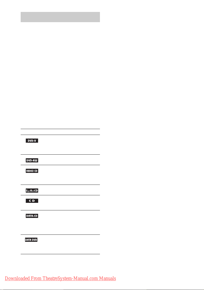
• The following symbols are used in this
manual.
Symbol Meaning
Functions available for DVD
VIDEOs, DVD-Rs/DVD-RWs in
video mode, and DVD+Rs/
DVD+RWs
Functions available for DVD-RWs
in VR (Video Recording) mode
Functions available for VIDEO
CDs (including Super VCDs or CDRs/CD-RWs in video CD format or
Super VCD format)
Functions available for Super Audio
CDs
Functions available for music CDs
or CD-Rs/CD- RWs in music CD
format
Functions available for DATA CDs
(CD-ROMs/CD-Rs/CD-RWs
containing MP3*
JPEG image files, and DivX*
video files)
2
Functions available for DATA
*
DVDs (DVD-Rs/DVD-RWs/
DVD+Rs/DVD+RWs) containing
3*4
DivX*
1
audio tracks,
video files
2*3*4
*1MP3 (MPEG1 Audio Layer 3) is a stan da rd form at
defined by ISO/MPEG which compresses audi o
data.
*2Asian, Australian, and Middle Eastern models only.
®
is a video file compression tec hnology,
*3DivX
developed by DivXNetworks, Inc.
*4DivX, DivX Certified, and assoc ia t ed logos a r e
trademarks of DivXNetworks, Inc. and are used
under license.
GB
6
Downloaded From TheatreSystem-Manual.com Manuals
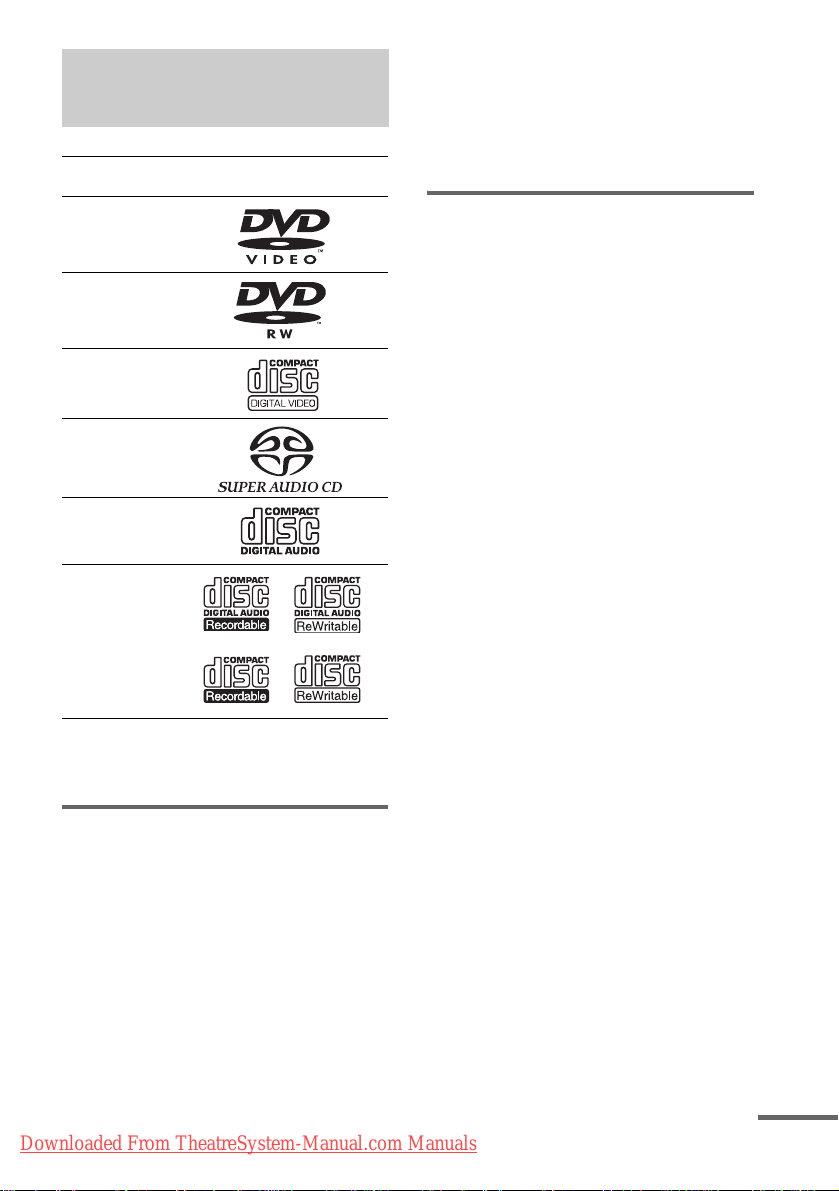
This System Can Play the Following Discs
Format of
discs
DVD VIDEO
Disc logo
The system can play DVD-ROMs/DVD+RWs/
DVD-RWs/DVD+Rs/DVD-Rs recorded in the
following formats:
– DivX video files of format conforming to
UDF.*
* Asian, Australian, and Middle Eastern models only.
Example of discs that the system cannot play
DVD-RW
VIDEO CD
Super Audio
CD
Audio CD
CD-R/CD-RW
(audio data)
(MP3 files)
(JPEG files)
The “DVD VIDEO” logo and “DVD-RW” logo are
trademarks.
Note about CDs/DVDs
The system can play C D - R O Ms/CD-Rs/CDRWs recorded in the followi ng formats:
– audio CD format
– video CD fo rmat
– MP3 audio tracks, JPEG image files, and
DivX video files * of format conforming t o
ISO 9660 Level 1/Level 2, or its extended
format, Joliet
The system cannot play the following discs:
• CD-ROMs/CD-Rs/CD-RWs other than those
recorded in the formats listed on page 7
• CD-ROMs recorded in PHOTO CD format
• Data part of CD -Extras
• DVD Audios
• DVD-RAMs
Also, the system cannot play the following
discs:
• A DVD VIDEO with a different region code
(page 9, 107).
• A disc that has a non-standard shape (e.g.,
card, heart).
• A disc wit h paper or stickers on i t .
• A disc that has th e adhe sive of celloph ane tap e
or a sticker still left on it.
Notes about CD-R/CD-RW/DVD-R/
DVD-RW/DVD+R/DVD+RW
In some cases, CD-R/CD-RW/DVD-R/DVD-RW/
DVD+R/DVD+RW cannot be played on this system
due to the recording quality or physical condition of the
disc, or the characterist i cs of the recording device and
authoring software.
The disc will not play if it has not been correctly
finalized. For more information, see the oper ati n g
instructions for the recording device.
Note that discs created in the Packet Write format
cannot be played.
Music discs encoded with
copyright protection
technologies
This product is designed to play back dis cs tha t
conform to the Compact Disc (CD) standar d.
Recently, various music discs encoded with copyright
protection technolog ies are marketed by some record
companies. Please be aware that among those discs,
Downloaded From TheatreSystem-Manual.com Manuals
continued
GB
7
there are some that do not conform to the CD standard
and may not be playable by this product .
Note on DualDisc
A DualDisc is a two sided disc produc t w hi ch
mates DVD recorded material on one side with
digital audio mat erial on the other side.
However, since t he audi o mate rial side doe s not
conform to the Compact Disc (CD) standard,
playback on this product is not guaranteed.
Note on PBC (Playback Control) (VIDEO CDs)
This system conforms to Ver. 1.1 and Ver. 2.0 of
VIDEO CD standards. You can en joy two ki nds
of playback depending on the disc type.
Disc type You can
VIDEO CDs
without PBC
functions
(Ver. 1.1 discs)
VIDEO CDs
with PBC
functions
(Ver. 2.0 discs)
Enjoy video playback (moving
pictures) as well as music.
Play interactive software using
menu screens displayed on the
TV screen (PBC Playback), in
addition to the video playback
functions of Ver. 1.1 discs.
Moreover, you can play highresolution still pictures, if they
are included on the disc.
About Multi Session CD
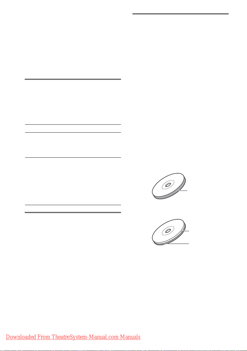
About the Super Audio CD
Super Audio CD is a new high-quality audio
disc standard where music is reco rded in the
DSD (Direct Stream Digital) format
(conventional CDs are recorded in the PCM
format). Th e DSD format , using a sampling
frequency 64 times higher than that of a
conventional CD, and with 1-bit quantization,
achieves both a wide frequency range and a wide
dynamic range across the audible frequency
range, and so pro vi des music reproduct i on
extremely faith ful to the original sound.
Types of Super Audio CDs
There are two types of di scs, depending on the
Super Audio CD layer and CD layer
combination.
• Super Audio CD la yer: A high-density
signal layer for Super Audio CD
•CD layer*
conventional CD pl ayer
Single layer disc
(a disc with a single Super Audio CD layer)
Hybrid disc*
(a disc with a Super Audio CD layer and a CD layer)
1
: A layer that is readable by a
Super Audio CD
layer
2
• This system can play Multi Session CDs when
an MP3 audio track is contained in the fi r st
session. Any subs equent MP3 audio tracks
recorded in later sessions can also be played
back.
• This system can play Multi Session CDs when
a JPEG image file is contained in th e fi rst
session. Any subs equent JPEG image fi le s
A Super Audio CD la yer consists of the 2
channel area or the multi-channel area.
recorded in later sessions can also be played
back.
• If audio tracks and images in music CD format
or video CD format are recorded in the first
session, only the first session will be pla ye d
back.
GB
8
Downloaded From TheatreSystem-Manual.com Manuals
3
CD layer*
Super Audio CD
3
layer*
• 2 channel area: An area in which 2 channel
stereo tracks are recorded
• Multi-channel area: An area in which multichannel (up to 5.1 channels) tracks ar e
recorded
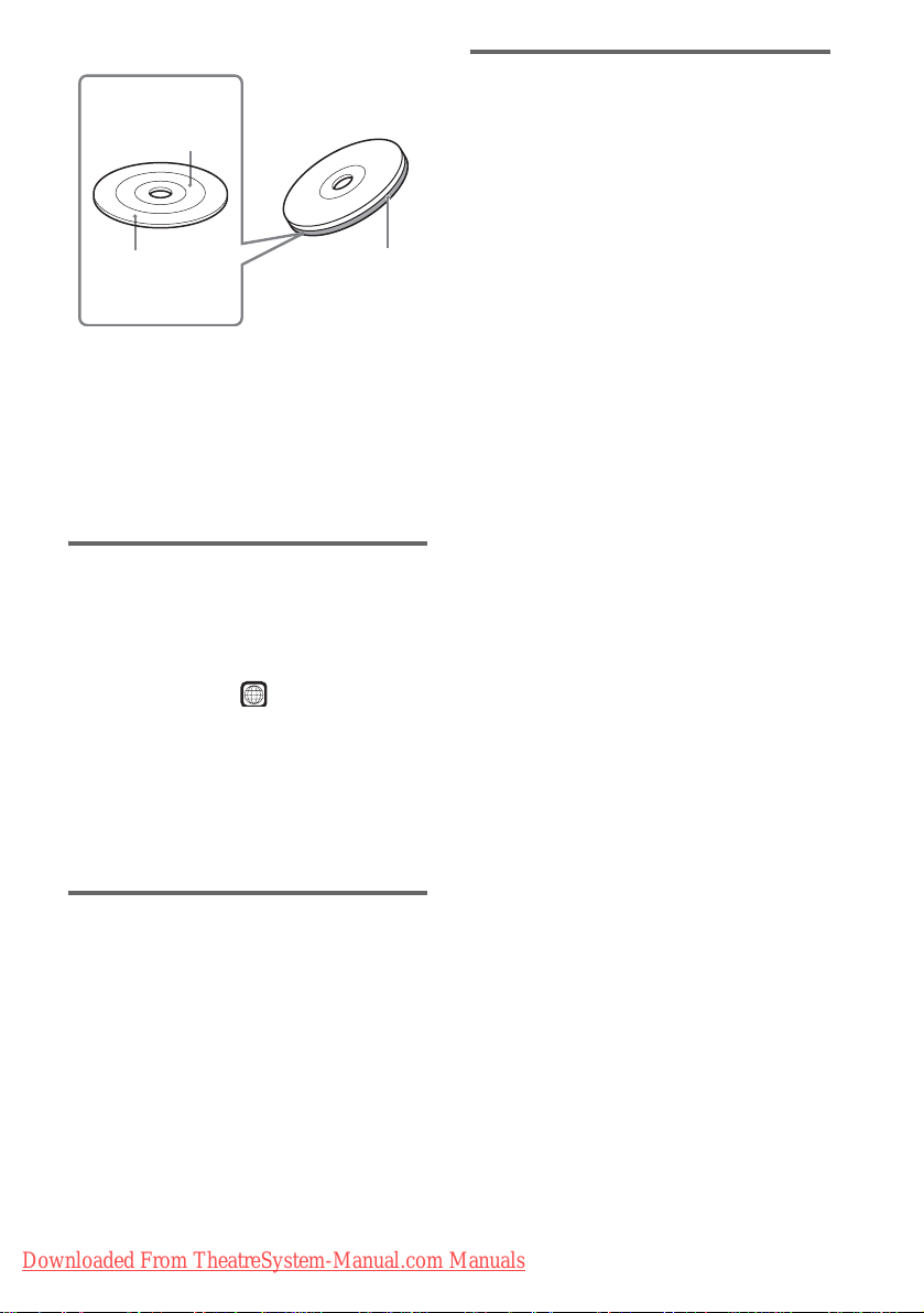
2 channel area*
Multi channel area*
*1You can play th e CD layer on a conve ntional CD
player.
*2Since both layers are on one side, it is not necessary
to turn the disc over.
*3To select a layer, see “Selecting a Playback Area for
a Super Audio CD” (page 49).
*4To select an area, see “Selecting a Playback Area for
a Super Audio CD” (page 49).
4
4
Super Audio CD
layer
Region code
Your system has a region code printed on the
back of the unit and will only play DVDs labeled
with the same region code.
Copyrights
This product inc or porates copyright prot ection
technology that is protecte d by U.S. p atents and
other in tellectua l p roperty ri g hts. Use of this
copyright pr ot ection technology must be
authorized by Macrovision, and is intended for
home and other limited viewing uses onl y unless
otherwise authorized by Macrovision. Reverse
engineering or disassembly is prohibited.
This system incorporates with Dolby*
and Dolby Pro Logic ( II) adaptive matrix
surround decoder and the DTS*2 Digital
Surround System.
*1Manufactured under license from Dolby
Laboratories.
“Dolby,” “Pro Logic,” and the double-D symbol are
trademarks of Dolby Laboratories.
*2Manufactured under license from Digital Theater
Systems, Inc.
“DTS” and “DTS Digital Surround” are trademarks
of Digital Theater Systems, Inc.
1
Digital
DVD VIDEOs labeled will also play on this
ALL
system.
If you try to play any other DVD VIDEO, the
message [Pla yback prohibited by area
limitations.] will appear on the TV screen.
Depending on the DVD VIDEO, no region code
indication may be given even though playing the
DVD VIDEO is prohibited by area restrictions.
Note on playback operations of DVDs and VIDEO CDs
Some playback operations of DVDs and VIDEO
CDs may be intentionally set by software
producers. Since this system plays DVDs and
VIDEO CDs according to the disc contents the
software producers designed, some playback
features may not be available. Also, refer to the
instructions supplied with the DVDs or VIDEO
CDs.
Downloaded From TheatreSystem-Manual.com Manuals
GB
9
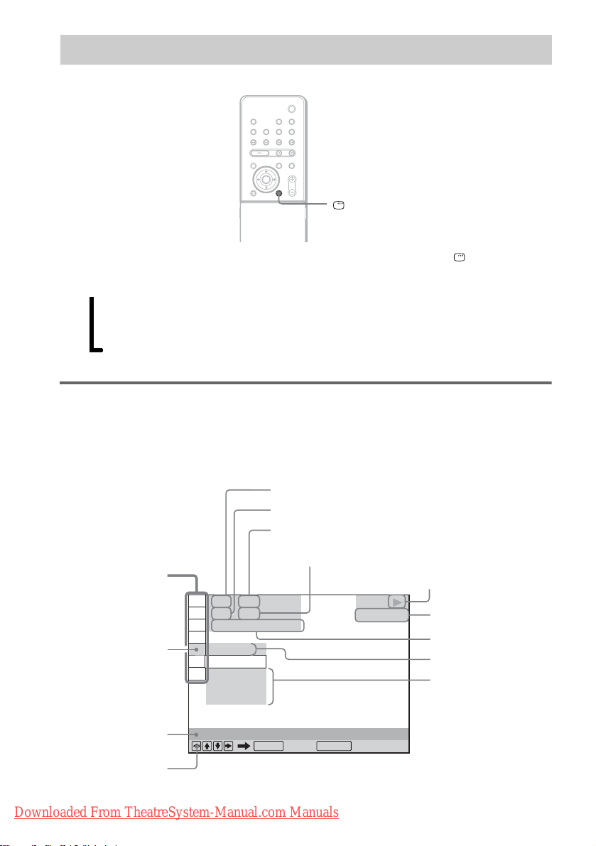
Guide to the Control Menu Display
DISPLAY
Use the Control Menu to select a function and to view related information. Press DISPLAY
repeatedly to turn on or change the Control Menu display as follows:
Control Menu display 1
,
m
Control Menu display 2 (appear s f or certa in discs only)
m
Control Menu display off
Control Menu display
The Control Menu display 1 and 2 will show different items depending on the disc type. For details
about each item, see the pages in parentheses.
Example: Control Menu display 1 when playing a DVD VIDEO.
Currently playing title number*
Currently playing chapter number*
Total number of titles*
Total number of chapters*
Control Menu items
)
)
1 : 3 2 : 5 5
Selected item
1 2 ( 2 7
1 8 ( 3 4
T
OFF
OFF
DISC
TITLE
CHAPTER
Function name of
selected Control
Menu item
Operation message
GB
10
Downloaded From TheatreSystem-Manual.com Manuals
REPEAT
ENTER DISPLAY
Quit:
1
2
DVD VIDEO
1
2
Playback status
(N Playback, X
Pause,
x Stop, etc.)
Type of disc being
played*
Playing time*
Current setting
Options
3
4

*1Displays the scene number for VIDEO CDs (PBC is on), track number for VIDEO CDs/Super Audio CDs/CDs,
album number for DATA CDs. DivX video album number for DATA DVDs/DATA CDs (Asian, Australian, and
Middle Eastern models only).
*2Displays the inde x number for VIDEO CDs/Super Audio CDs, MP3 audio track num be r , or JPEG image file
number for DATA CDs. DivX video file number for DATA DVDs/DATA CDs (Asian, Australian, and Middle
Eastern models only).
*3Displays Super VCD as “SVCD.” Displays “MP3” in the Control Menu display 1 or “JPEG” in the Control Menu
2 for DATA CDs.
*4Displays the date for JPEG files.
To turn off the display
Press DISPLAY.
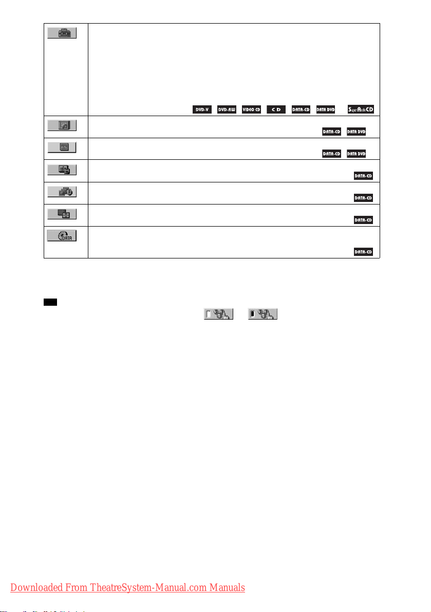
List of Control Menu items
Item Item Name, Function, Relevant Disc Type
[TITLE] (page 61)/[SCENE] (page 61)/[TRACK] (page 61)
Selects the title, scene, or track to be played.
[CHAPTER] (page 61)/[INDEX] (page 61)
Selects the chapter or index to be pla ye d.
[INDEX] (page 61)
Displays the index and selects the index to be played.
[TRACK] (page 61)
Selects the track to be played.
[ORIGINAL/PLAY LIST] (page 49)
Selects the type of tit les ( DVD-RW) to b e play ed, th e [ORIGINAL] o ne, or an edit ed [ PLAY
LIST].
[TIME/TEXT] (page 62)
Checks the elapsed time and the remaining playback time.
Input the time code for picture and mu sic searching.
Displays the DVD/CD text or the MP3 track name.
*
[MULTI/2CH] (page 49)
Selects the playback area on Super Audio CDs when available.
[PROGRAM] (page 45)
Selects the track to play in the ord er you wa nt.
[SHUFFLE] (page 47)
Plays the track in random orde r .
[REPEAT] (page 47)
Plays the entire disc (all titles/all tracks/all albums) repeatedly or one title/chapter/track/album
repeatedly. *
[PARENTAL CONTROL] (page 75)
Sets to prohibit playback on this system.
1
1
Downloaded From TheatreSystem-Manual.com Manuals
continued
11
GB
[SETUP] (page 90)
[QUICK] Setup (page 39)
Use Quick Setup to choose the desired language of the on-screen display, the aspect ratio of
the TV, and the size of the speakers you are using.
[CUSTOM] Setup
In addition to the Quick Setup setting, you can a djust various other settings.
[RESET]
Returns the settings in [ S E T UP] to the default setting .
*
[ALBUM] (page 61)
Selects the album to be played. *
[FILE] (page 61)
Selects the JPEG image file or DivX video file*1 to be played. *
2
[DATE] (page 67)
*
Displays the date the picture was taken by a digit al came ra.
2
[INTERVAL] (page 56)
*
Specifies the duration for which the slides are displayed on the screen.
2
[EFFECT] (page 57)
*
Selects the effects to be used for changing slides during a slide show.
2
[MODE (MP3, JPEG)] (page 55)
*
Selects the data type; MP3 audio track (AUDIO), JPEG image file (IMAGE) or both
1
1
1
(AUTO) to be played when playing a DATA CD.
*1Asian, Australian, and Mi ddl e Easte r n models only.
*2These items are not displayed when playing a DATA CD with DivX video file . (A sia n, Aust ralian, and Middle
Eastern models only)
Tip
• The Control Menu icon indicator lights up in green when you select any item except [OFF]
t
([PROGRAM], [SHUFFLE], [REPEAT] only). The [ORIGINAL/PLAY LIST] indicator lights up in green when
you select [PLAY LIST] (default setting). The [M ULTI /2C H] indi cator lights up in green when you select the
multi-channel playback area on a Super Audio CD.
GB
12
Downloaded From TheatreSystem-Manual.com Manuals
Getting Started
Unpacking
Check that you have the following items:
•Speakers (5)
• Subwoofer (1)
• Posts (long × 4, short × 4)
• Bases (4)
• Terminal covers (SS-TS47 × 2, SS-TS45 or
SS-TS46 × 2)
• Screws (20)
• Surround amplifier (1)
• IR transmitter* (1)
• IR receiver* (1)
• IR receiver stand (1 )
• Speaker base (1)
• AM loop antenna (aeri al) (1)
• FM wire antenna (aeri al) (1)
• Speaker cords (5 m × 6)
(16.5 ft. × 6)
• Video Cord (1)
• Remote Co mmander (remote) (1)
• Size AAA (R03) batteries (2)
• Wall-mount pads
• Operating Instructions
• Speaker an d TV connections (card) (1)
* The cords of the IR transmitter and IR receiver are
for this system only. You cannot use a commercially
available extension cord .
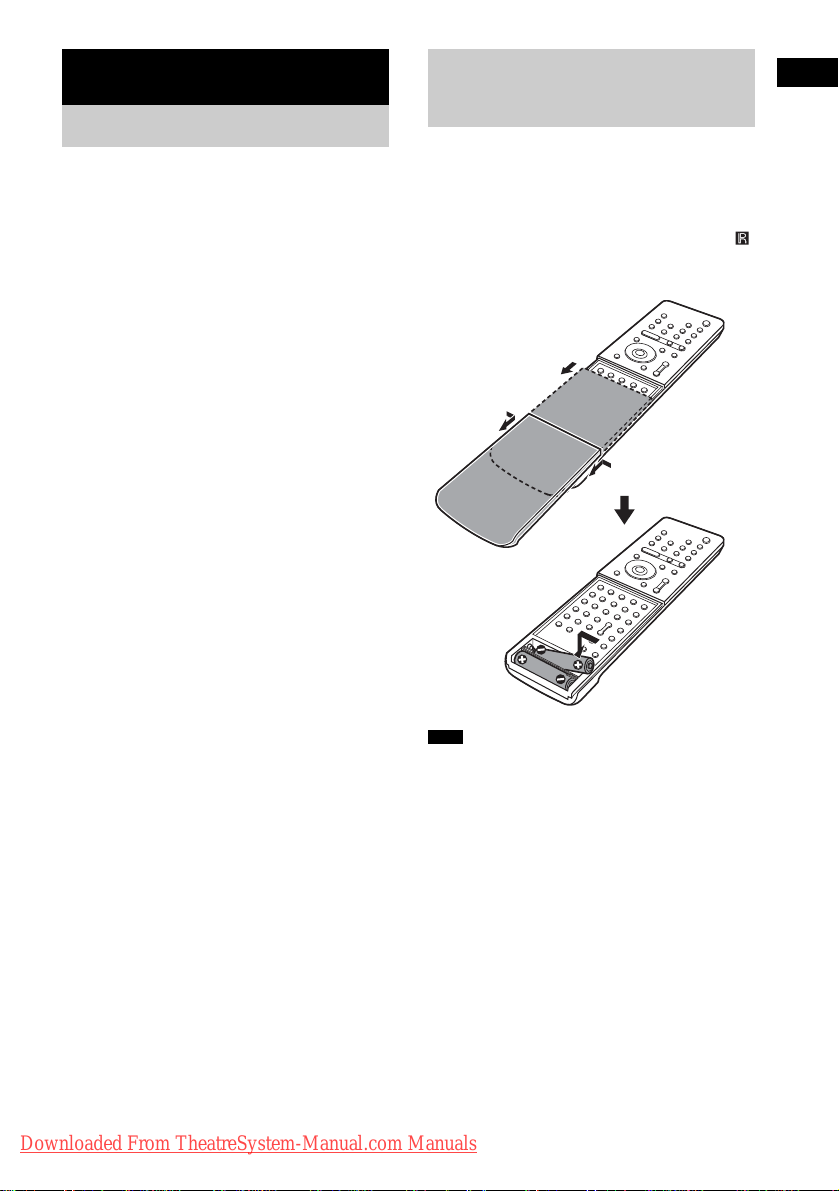
Inserting Batteries into the Remote
You can control the system using the supplied
remote. Insert two size AAA (R03) batteries b y
matching the 3 and # ends on the batteries to
the markings inside the compartment. When
using the remote, point it at the remote s ensor
on the system.
1 Slide open the cover.
2
2 Remove the
cover by pinching
the sides.
Note
• Do not leave the remote in an extremely hot or humid
place.
• Do not use a new battery with an old one.
• Do not drop any foreign object into the remote casing,
particularly when replac ing th e ba tteries.
• Do not expose the remote sensor to dir ect li ght from
the sun or lighting apparatus. Doi ng so ma y c au se a
malfunction.
• If you do not intend to use the remote for an extended
period of time, remove the batteries to avoid possible
damage from battery leakage and corros ion.
Getting Started
Downloaded From TheatreSystem-Manual.com Manuals
13
GB

Hookup Overview
Perform all connections and settings by following Steps 1 to 8.
“Step 1: Speaker System Hookup” (page 15)
“Step 2: Antenna (Aerial) Hookup” (page 26)
“Step 3: TV Hookup” (page 27)
“Step 4: Other Component Hookup” (page 34)
“Step 5: Connecting the AC Power Cord (Mains Lead)” (page 36)
“Step 6: Turning off the Demonstration” (page 36)
“Step 7: Adjusting the Wireless System” (page 37)
“Step 8: Performing the Quick Setup” (page 39)
Video signal is se nt to th e TV , and is output from the TV s creen; audio signals ar e pr ocessed by this
system and outpu t fro m the speakers of this system. You can also en j oy s ound of other sources, such
as TV programs, in ad di tion to DVDs or CDs.
GB
14
Downloaded From TheatreSystem-Manual.com Manuals
Step 1: Speaker System Hookup
Connect the supplied speaker system using the supplied speaker cords by matching the colors of the
jacks to those of the cords. Do not connect any speakers other than those suppli ed with this system.
To obtain the best possible surround sound, specify the speaker parameters (distance, level, etc.) on
page 95.
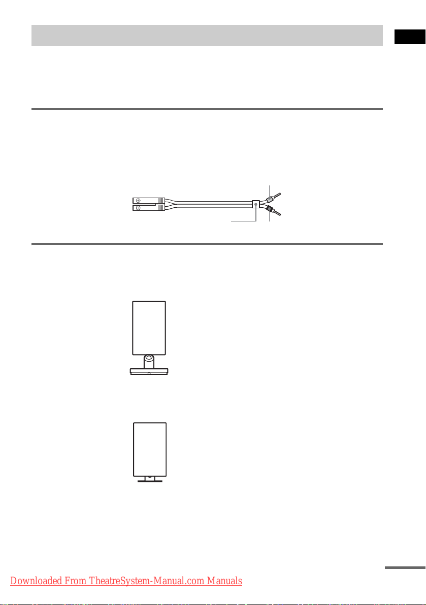
Required cords
Speaker cords
The connector and the color tube of the speaker cor ds are the same colo r as the label of the jacks to be
connected.
Gray
(+)
(–)
Color tube
Required equipments for the wireless system
IR transmitter
Transmits the sound by the infrared ray. Connect it to the system.
(+)
(–)
Black
Getting Started
IR receiver
Receive the sound by the infrared ray. Connect it to the surround amplifier.
Downloaded From TheatreSystem-Manual.com Manuals
continued
15
GB
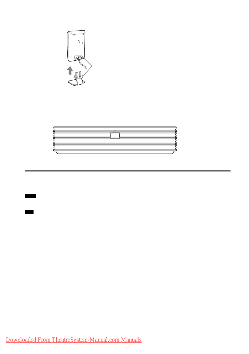
When using the IR receiver stand, attach th e stand so that bot h delta mar ks on the I R receiver and stan d
are aligned.
IR receiver
Delta marks
IR receiver stand
Surround amplifier
Receive the sound f rom the IR receiver a nd s end to the surround speakers.
Connect the sur ro u nd speakers and the IR receiver to the surr ound amplifier.
POWER/ON LINE
POWER
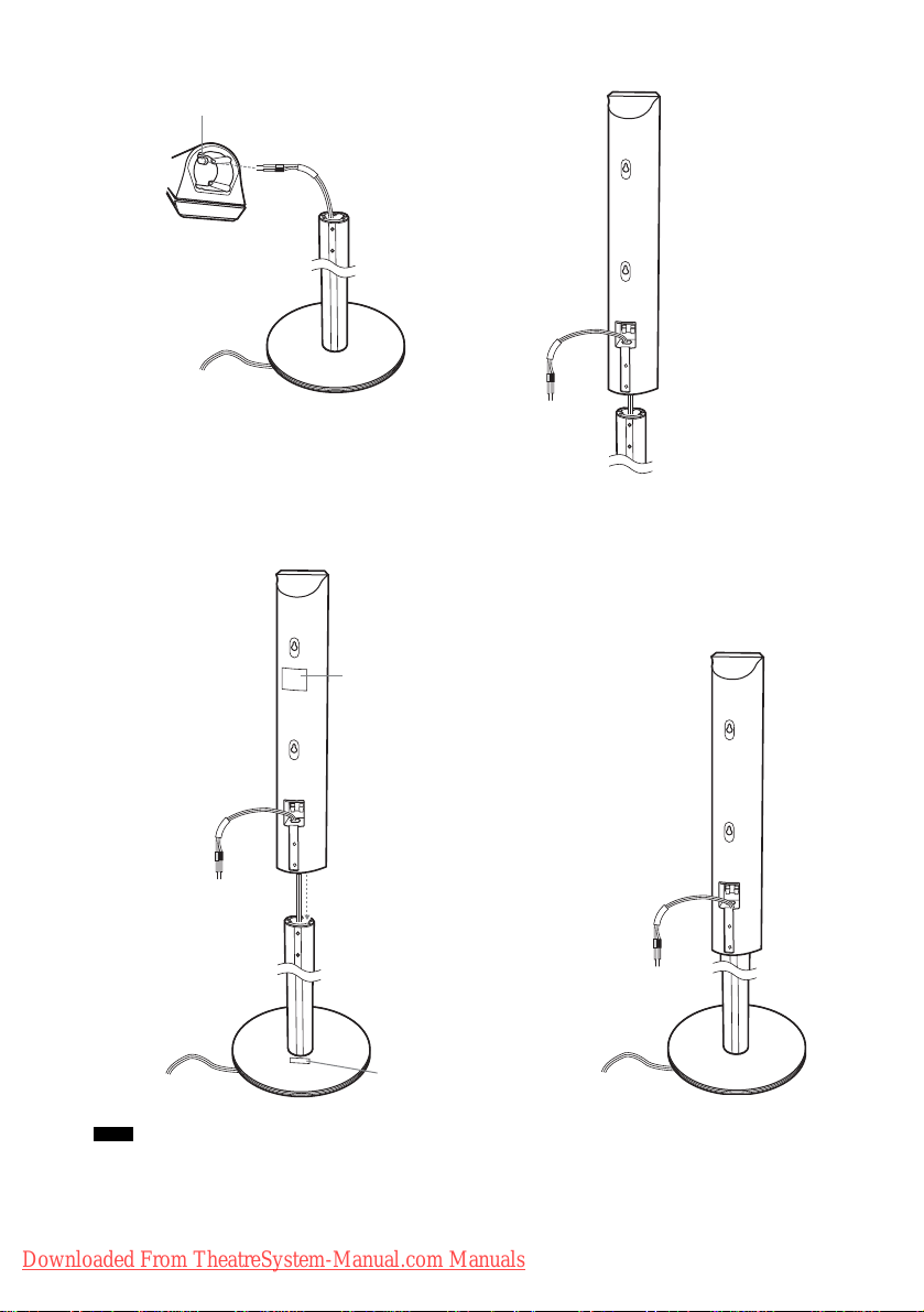
Attaching the speaker stand to the speaker
Before conne cting the speaker s, at tach the speaker stand to the speaker.
Note
• Spread a cloth on the floor to avoid damaging the floor.
Tip
• You can use the speaker without the speaker stand by installing it on the wall (page 23).
1 Insert the post into the base.
GB
16
Downloaded From TheatreSystem-Manual.com Manuals
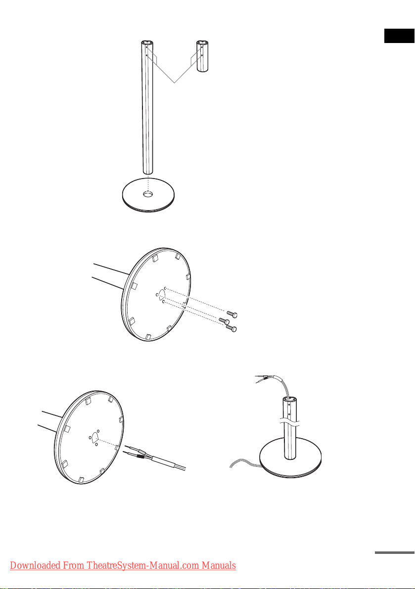
The long post is for floor use, the short post is for tabletop use.
Post (long)
or
Screw holes
Base
2 Secure the base to the post by screws.
Post (short)
Bottom of the base
Screws (3)
Getting Started
3 Draw the speaker cord through the hole on the base, then stand it up.
Bottom of the
base
,
Speaker cord
Downloaded From TheatreSystem-Manual.com Manuals
continued
17
GB
4 Draw the speaker cord through the hole on the speaker.
Hole
Speaker
Speaker cord
Speaker
,
5 Mount the speaker on the post.
Mount the spea ker so that the spea ker names inscribe d on the speaker and base are alligned.
Front speaker: SS-TS47
Surround speaker: SS-TS46B
,
Front speaker: SS-TS47
Surround speaker: SS-TS46B
Note
• Do not catch the speaker cord between the speaker and the post.
• Do not drop the speaker when mounting.
GB
18
Downloaded From TheatreSystem-Manual.com Manuals
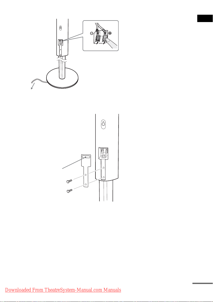
6 Connect the speaker cord to the speaker, then adjust the length of the speaker cord.
Adjust the length of the speaker cord.
7 Attach the terminal cover to the speaker by screws.
Terminal cover
(SS-TS47 for the front speakers,
SS-TS45 or SS-TS46 for the
surround speakers)
Getting Started
Before attaching, ensure
that the speaker name
inscribed on the terminal
cover is for the correct
speaker.
Screws (2)
Downloaded From TheatreSystem-Manual.com Manuals
continued
19
GB
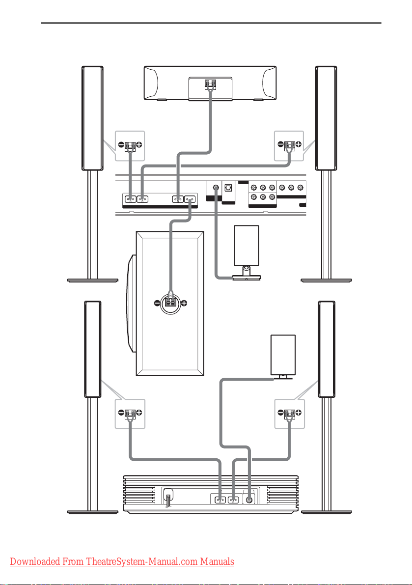
Connectin g the speakers
N
DAV-FX999W
Front speaker (R)
Rear side of the front
speaker
FRONT R FRONT L CENTER WOOFER
SPEAKER
Center speaker
DIR-T1
Rear side of the front
speaker
AUDIO IN
VIDEO
RL
OPTICAL
DIGITAL IN
RL
AUDIO IN
SAT
IR transmitter
VIDEO IN
COMPONENT VIDEO OUT
VIDEO IN
SAT
IR receiver
YPB/CBPR/C
(DVD ONLY)
R
MO
Front speaker (L)
Subwoofer
Rear side of
the surround
speaker
SPEAKER DIR-R2
SURROUND L SURROUND R
Surround speaker (L)
GB
20
Downloaded From TheatreSystem-Manual.com Manuals
Surround amplifier
Rear side of
the surround
speaker
Surround speaker (R)
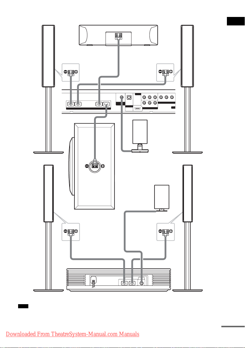
DAV-FX1000W
N
Front speaker (R)
Center speaker
Front speaker (L)
Getting Started
Rear side of the front
speaker
FRONT R FRONT L CENTER WOOFER
SPEAKER
Subwoofer
OPTICAL
DIR-T1
DIGITAL IN
SAT
HDMI
OUT
IR transmitter
Rear side of the front
speaker
AUDIO IN
VIDEO IN
VIDEO
(DVD ONLY)
RL
RL
AUDIO IN
SAT
YPB/CBPR/C
COMPONENT VIDEO OUT
VIDEO IN
IR receiver
(DVD ONLY)
R
MO
Rear side of
the surround
speaker
SPEAKER DIR-R2
SURROUND L SURROUND R
Surround speaker (L)
Rear side of
the surround
speaker
Surround amplifier
Note
• Do not set the speakers in an inclined position .
Downloaded From TheatreSystem-Manual.com Manuals
Surround speaker (R)
continued
21
GB
• Do not place the speakers in locations that are:
– Extremely hot or cold
– Dusty or dirty
– Very humid
– Subject to vibrations
– Subject to direct sunlight
• Use caution when placing the speakers and/or speaker stands (not supplied) that are attached with the speakers on
a specially treated (waxed, oile d, pol ished, etc.) floor, as staining or disco lora tion may result.
• When cleaning, use a soft cloth such as a cleaning cloth for glasses.
• Do not use any type of abrasive pad, scouring powd er, or sol ve nt suc h a s al co hol or be nzine.
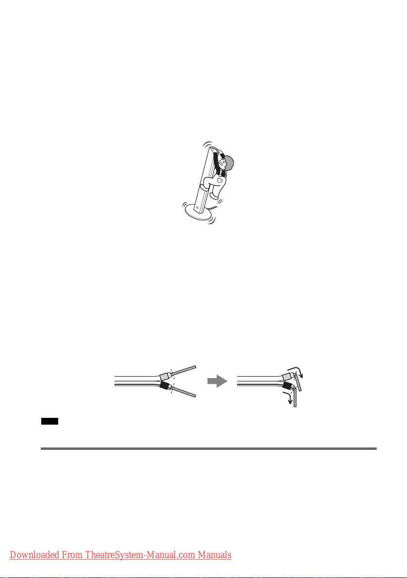
• Do not lean or hang on the speaker, as the speak er ma y f al l down.
Notes on placing IR transmitter and IR receiver
• Do not install the IR receiver in a place ex pose d to direct sunlight or strong light such as an inc and es ce nt lam p.
• The cords of the IR transmitter and IR receiver are for this system only. You cannot use a commercially available
extension cord.
Notes on placing the surround amplifier and speaker base
• Do not step and place objects other than supplied speakers on the surround amplifier and speaker base.
• When you install the speaker on the surround amplifier or speaker base, make sure the speaker is properly stacked.
To connect the speaker cords
Connect the speaker cords after bending the bare wire at the end of the insulation. This prevents the
speaker i n sulation from being inserted in the speaker terminal.
Note
• Do not catch the speaker cord insulation in the S PEAKER jack.
Avoiding short-circuiting the speakers
Short-circuiting of the speakers may damage the system. To prevent this, be sure to follow these
precautions w hen conne cting the speakers. Ma ke sure th e bare wire of each spea ker cord do es not tou ch
another speaker terminal or the bare w ir e of another speake r cord.
GB
22
Downloaded From TheatreSystem-Manual.com Manuals
Examples of poor conditions of the speaker cord
Stripped speaker cord is
touching another speaker
terminal.
Stripped cords are touching each
other due to excessive removal of
insulation.
After connecting all the components, speakers , and AC power cord (mains lead) , outpu t a test to ne to
check that all the speakers are connecte d correctly. For details on outputting a test tone, see page 96.
If no sound is heard from a spe aker while outputting a test ton e, or a test tone is output from a speaker
other than the one curr ently d ispla yed on th e Setu p Disp lay, t he spe aker may be short -circ uite d. If this
happens, check the speaker connection again.
Note
• Be sure to match the speaker cord to the appropriate terminal on the components: 3 to 3, and # to #. If the cords
are reversed, the sound will lack ba ss an d ma y be distorted.
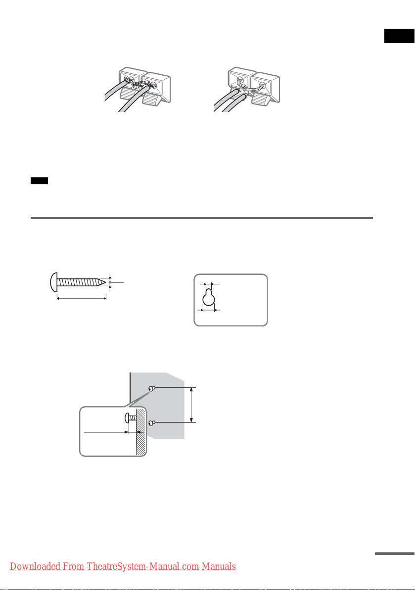
Installing the speakers on the wall
1 Prepare screws (not supplied) that are suitable for the hole on the back of each speaker.
See the illustrations below.
Getting Started
25 mm (1 inch)
4 mm (
5
/32 inch)
4.6 mm
3
/16 inch)
(
10 mm
13
/32 inch)
(
2 Fasten the screws to the wall.
The screws should protrude 7 to 8 mm (9/32 to 11/32 inch).
165 mm (6 1/2 inch)
7 to 8 mm
9
(
/32 to 11/32 inch)
3 Peel the seals off the two screw points on the rear of the speaker.
Downloaded From TheatreSystem-Manual.com Manuals
Hole on the back of
the speaker
continued
23
GB
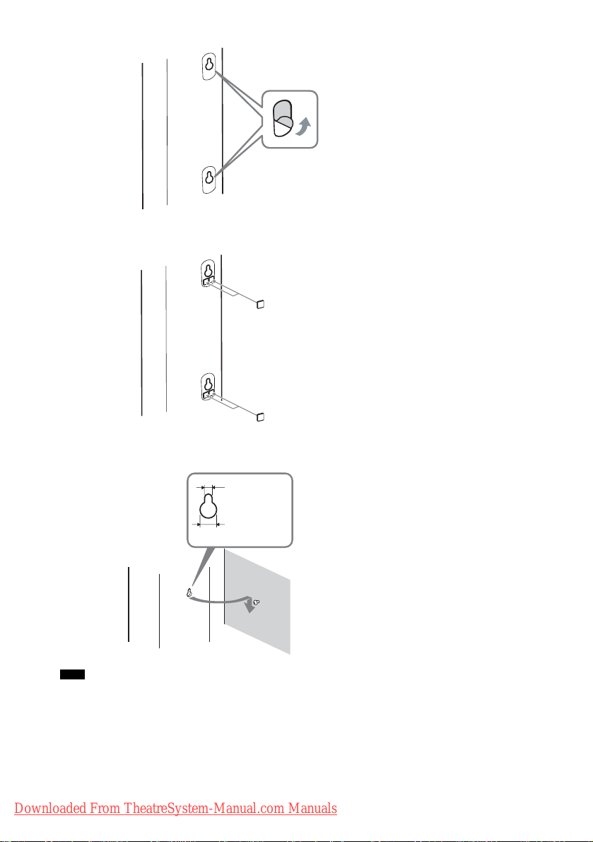
4 Attach the wall-mount pads on the rear side of the speaker.
Wall-mount pads
(7 × 7 mm, 3 mm thick)
9
(
/32 × 9/32 inch, 1/8 inch thick)
5 Hang the speakers on the screws.
4.6 mm
3
(
/16 inch)
10 mm
13
/32 inch)
(
Note
• Use screws that are suitable for the wall material and strength. As a plaster board wall is especially fragile, attach
the screws securely to a beam and fasten them to the wall. Install the speakers on a vertical and flat wall where
reinforcement is applied.
• Contact a screw shop or in sta ller regarding the wall mate r ia l or sc rew s to be used.
• Sony is not responsible for accident or damage caused by improper installation, insufficient wall strength or
improper screw installation, natural cala mit y, etc.
GB
24
Downloaded From TheatreSystem-Manual.com Manuals
Hole on the back of
the speaker
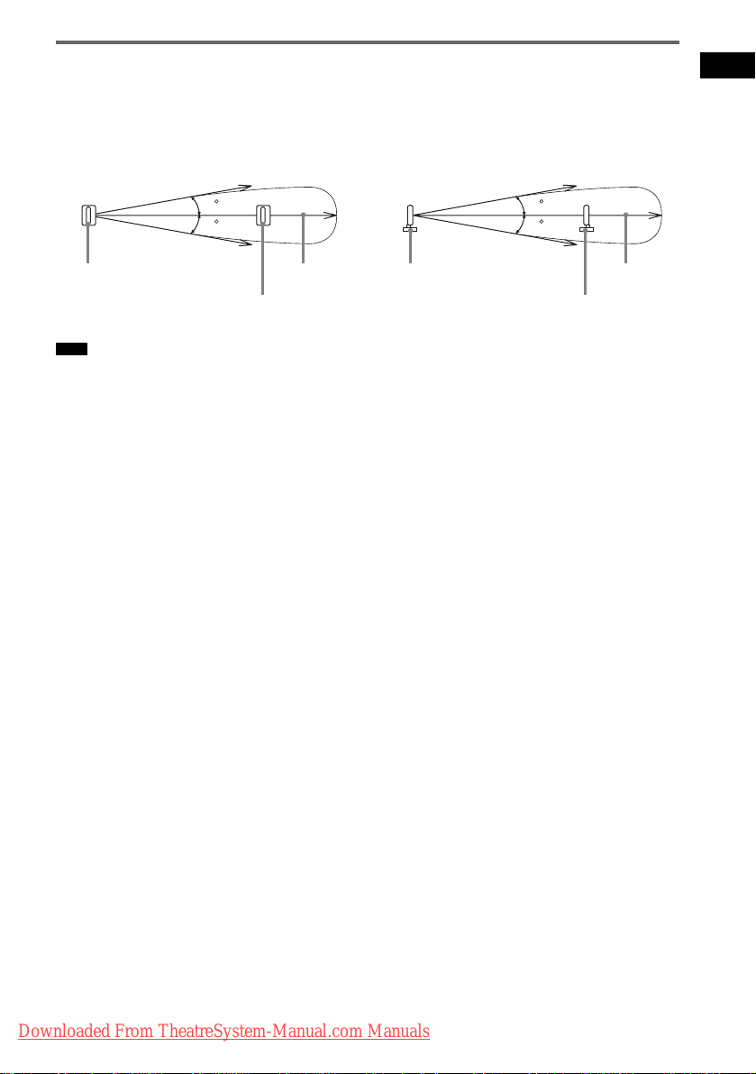
About the wireless system
This wireless system adopts the Digital Infrared Audio Transmission system (page 105). The following
diagram indicates the infrared transmission area (the range that the infrared rays can reach).
Getting Started
Top view
Infrared signal
10
10
IR transmitter
IR receiver
Note
• Do not install the IR receiver in a place exposed to direct sunlight or strong light such as an incandescent lamp.
• Do not use the IR transmitter or IR receive r tha t is not supplied with the system.
Approx. 10m
Side view
IR transmitter
Infrared signal
10
10
Approx. 10m
IR receiver
Downloaded From TheatreSystem-Manual.com Manuals
25
GB

Step 2: Antenna (Aerial) Hookup
Connect the supplied AM/FM antennas (aerials) for listening to the radio.
AM loop antenna (aerial)
FM wire antenna (aerial)
Note
• To prevent noise pickup, keep the AM loop antenna (aerial) away from the system and other components.
• Be sure to fully extend the FM wire antenna (a erial).
• After connecting the FM wire antenna (aerial), keep it as horizontal as possible.
Tip
• When you connect the supplied AM loop antenna (aerial), cord (A) or cord (B) can be connected to either terminal.
A
B
• If you have poor FM reception, use a 75-ohms coaxial cable (not supplied) to connect the system to an outdoor FM
antenna (aerial) as shown below .
System
GB
26
Downloaded From TheatreSystem-Manual.com Manuals
Outdoor FM antenna (aerial)
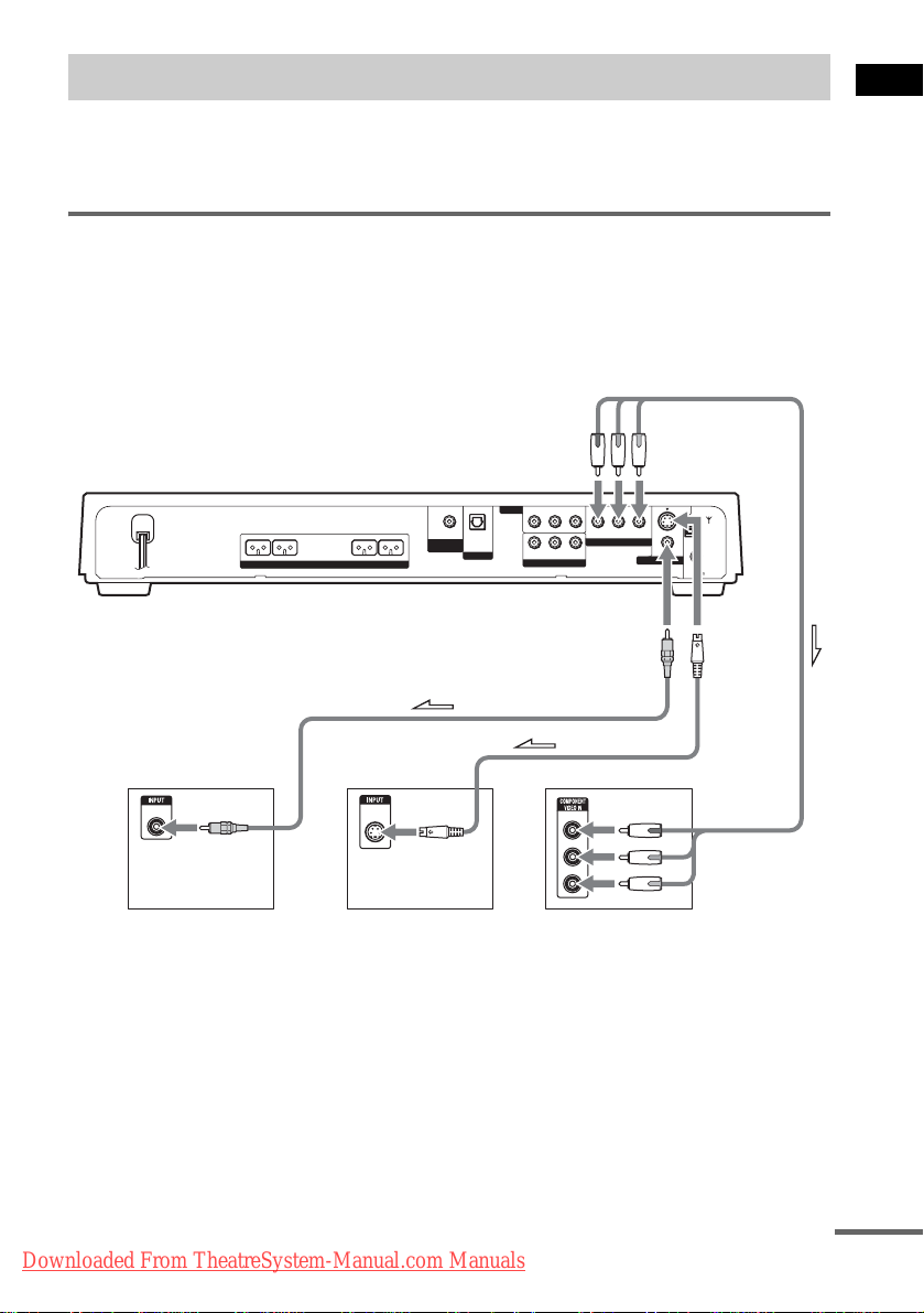
Step 3: TV Hookup
First, perform the vi deo connection, and the n audio connection.
With your TV’s audio output connected to this system, you can listen to TV sound through the system
speakers.
Connecting the video/HDMI* cords
Sends a played back DVD image to a TV.
DAV-FX999W
Check the jacks of your TV, and choose the A, B, or C connection. Picture quality improves in order
from A (stand ar d) to C (component).
To COMPONENT
VIDEO OUT
Getting Started
R
VIDEO
MONITOR OUT
(DVD ONLY)
S VIDEO
AM
COAXIAL
FM
75
To
S VIDEO
FRONT R FRONT L CENTER WOOFER
SPEAKER
AUDIO IN
VIDEO IN
VIDEO
RL
OPTICAL
DIR-T1
DIGITAL IN
RL
SAT
AUDIO IN
SAT
YPB/CBPR/C
COMPONENT VIDEO OUT
VIDEO IN
(DVD ONLY)
To VIDEO
AB C
VIDEO
IN
TV TV with S VIDEO IN jack
S VIDEO
IN
Y
PB/CB
PR/CR
TV with COMPONENT
VIDEO IN jacks
Downloaded From TheatreSystem-Manual.com Manuals
continued
27
GB
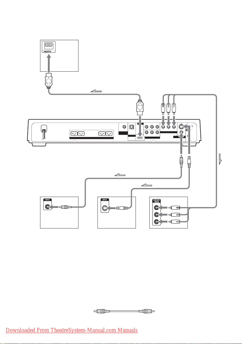
DAV-FX1000W
Check the jacks of your TV, and choose the A, B, C, or D connection. Picture quality improves in
order from A (standard) to D (component).
TV with HDMI* IN jack
IN
D
YPB/CBPR/C
(DVD ONLY)
R
MONITOR OUT
To COMPONENT
VIDEO OUT
S VIDEO
(DVD ONLY)
AM
VIDEO
COAXIAL
FM
75
To
S VIDEO
To HDMI* OUT
FRONT R FRONT L CENTER WOOFER
SPEAKER
AUDIO IN
VIDEO IN
VIDEO
RL
OPTICAL
DIR-T1
DIGITAL IN
SAT
HDMI
(DVD ONLY)
OUT
RL
AUDIO IN
SAT
COMPONENT VIDEO OUT
VIDEO IN
To VIDEO
AB C
VIDEO
IN
TV TV with S VIDEO IN jack
* HDMI (high-definition multimedia interface) (DAV-FX1000W only)
The system is based on version 1.1 of High-De f ini tion Multimedia Interface Specifi cat ions.
The system incorporates High-Definition Multimedia Interface (HDMI
S VIDEO
IN
Y
PB/CB
PR/CR
TV with COMPONENT
TV with COMPONENT
VIDEO IN jacks
VIDEO IN jacks
TM
) technology.
HDMI, the HDMI logo and High-Definition Multimedia Interface trademarks or registered trademarks of HDMI
Licensing LLC.
A To connect to a TV with the VIDEO IN jacks
Connect the video cord.
GB
28
Downloaded From TheatreSystem-Manual.com Manuals
Yellow
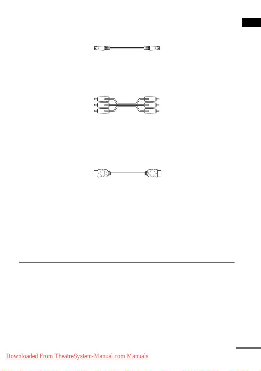
B To connect to a TV with the S VIDEO IN jack
Connect an S video cor d (not supplied). When using the S video jack in st ead of the video jacks, y our
TV monitor must also be connected via an S video jack. S video signals are on a separate bus from the
video signals and wi l l not be output through th e video jacks.
C To connect to a TV with the COMPONENT VIDEO IN jacks
Connect a component video cord (not supplied). To use the COMPONENT VIDEO OUT jacks (Y, PB/
C
B, PR/CR) instead of the video jacks, your TV monitor must be equipped with via COMPONENT
VIDEO IN jacks (Y, P
B/CB, PR/CR). If your TV acce pts progressiv e format signals, you must use this
connection and set th e output channel of the system to progressiv e format (page 29).
Green
Blue
Red
D To connect to a TV with the HDMI (high-definition multimedia
interface)/DVI (digital visual interface) input jack (DAV-FX1000W only)
Use a certified HDMI (hig h -d ef i ni tio n mul timedia interface) cord (n ot supplied) to enjoy high qu a lity
digital picture and sound through the HDMI OUT (high-definition multimedia interface out) jack.
Note that Super Audio CD sound is not output from the HDMI OUT (high-definition multimedia
interface out) jack.
To connect to a TV with DVI (digital visual interface) input
Use an HDMI (high-definition multime dia interfac e)-DVI (digital visu al interface) co nverter cord (not
supplied) with an HDMI (high-d ef ini tio n multimedia interface)-DVI (digital visual interface) ada ptor
(not supplied). The DVI (digi tal visual inte rface) jack wil l not accept any a ud i o signals. Furth ermore,
you cannot connect the HDMI OUT (high-definition multimedia interface out) jack to DVI (digital
visual interface) jacks that are not HDCP (high-b and widt h digi tal content protection) compliant (e.g.,
DVI (digital visual interface) jacks on PC displays).
When connecting to a standard 4:3 screen TV
Depending on the disc, the image may not fi t yo ur TV screen.
To change the aspect rat i o, see page 92.
Getting Started
Does your TV accept progress ive signals?
Progressive is the meth od for disp laying TV images wh ich reduces flickeri ng, and sharp ens the image.
To display using this method, you need to connect to a TV that accepts progressive signals.
Downloaded From TheatreSystem-Manual.com Manuals
continued
29
GB
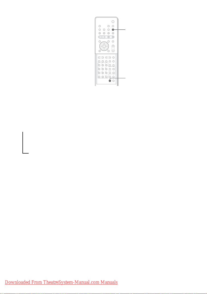
FUNCTION
PROGRESSIVE
With cover opened.
“P AUTO” or “P VIDEO” appears in the front panel display when the system output s progressive
signals.
1 Press FUNCTION repeatedly to select “DVD.”
2 Press PROGRESSIVE.
Each time you press PROGRESSIVE, the display changes as follows:
t P AUTO (PROGRESSIVE AUTO)
r
P VIDEO (PROGRESSIVE VIDEO)
r
INTERLACE
x P AUTO (PROGRESSIVE AUT O )
Select this setting when:
– your TV accepts progressive sign al s, and,
– the TV is connected to the COMPONENT VIDEO OUT jacks.
Normally select this under the above condition. This automaticall y detects the software type, and
selects the appropriate conversion method.
Note that the pictur e w i ll not be clear or no picture will appear if you sel ect these settings when
either of the above conditions is not met.
x P VIDEO (PROGRESSIVE VIDEO)
Select this setting when:
– your TV accepts progressive sign al s, and,
– the TV is connected to the COMPONENT VIDEO OUT jacks, and,
– you want to fix t he conversion met hod to PROGRESSIVE VIDEO for video-base d software.
Select this if the image is not clear when you select PROGRESSIVE AUTO.
Note that the pictur e w i ll not be clear or no picture will appear if you sel ect these settings when
either of the above conditions is not met.
x INTERLACE
Select this setting when:
– your TV does not accept progressive signals, or,
GB
30
Downloaded From TheatreSystem-Manual.com Manuals
 Loading...