

2-635-101-12(1)
DVD Home Theatre
System
Operating Instructions
D AV-DX170/DX250
©2005 Sony Corporation
3
WARNING
To prevent fire or shock hazard, do not
expose the unit to rain or mo ist u r e.
Caution – The use of optical instruments
with this product will increase eye
hazard.
For the customers in the U.S.A
This symbol is int ended to alert the us er to
the presence of uninsulated “d an ge ro u s
voltage” within the p ro du ct ’ s e n clo s u r e th at
may be of sufficient magnitude to constitute a risk of
electric shock to persons.
This symbol is int ended to alert the us er to
the presence of important operating and
maintenance (servicing) instructions in the
literature accompanying the ap pliance.
Owner’s Record
The model and seri al numbers are l ocated at t he rear of
the unit. Record the serial numb er in the space
provided below. Refer to them whenever you call upon
your Sony dealer regarding this product.
Model No. DAV-DX170/DX250
Serial No.______________
WARNING
This equipment has been tested and fou nd to co mply
with the limits for a Class B digital device, pursuant to
Part 15 of the FCC Rules. These limits are designed to
provide reasonable protection a gai nst harmful
interference in a residential installat ion. This
equipment generates, uses, and c an ra dia te radi o
frequency energy and, if not installed and used in
accordance with the instruc tions, may cause harmful
interference to radio commu nicati ons. However , ther e
is no guarantee that interference will not occur in a
particular installation. If thi s eq uipment does cause
harmful interference to radio or television reception,
which can be determined by turning the equipment off
and on, the user is encouraged to try to correct the
interference by one or more of the following measures:
– Reorient or relocate the rec eiv i n g antenna (aerial).
– Increase the separation between the equipment and
receiver.
– Connect the equipment into an outlet on a circuit
different from that to which the receiver is
connected.
– Consult the dealer or an experienced radio/TV
technician for help.
CAUTION
You are cautioned that any changes or modif icat ions
not expressly approved in this manual could void your
authority to operate this equipm ent .
Note to CATV system installer:
This reminder is provided to call the CATV system
installer’s attention to Article 820-40 o f th e N E C that
provides guidelines for proper ground ing a nd, in
particular, specifies that the cable ground shall be
connected to the grounding system of the building, as
close to the point of cable entry as practical.
For the customers in Canada
CAUTION
TO PREVENT ELECTRIC SHOCK, MATCH WIDE
BLADE OF PLUG TO WIDE SLOT, FULLY
INSERT.
Precautions
Safety
• If anything falls into the cabinet, unplug the unit and
have it checked by qualified per sonne l before
operating it any further.
• The unit is not disconnected from the AC power
source (mains) as long as it is connected to the wall
outlet (mains), eve n if the un it itself has been turned
off.
• Unplug the unit from the wall outlet (mains) if you do
not intend to use it for an extended period of time. To
disconnect the cord, pull it out by the plug, ne ver by
the cord.
Installing
• Allow adequate air circulation to prevent internal
heat buildup.
• Do not place the unit on surfaces (rugs, blanket s, etc.)
or near materials (curt ain s, dr aperies ) th at ma y blo ck
the ventilation slots.
• Do not install the unit near heat sources such as
radiators, or air ducts, or in a place subject to direct
sunlight, excessive dust, me c ha nic al vibration, or
shock.
• Do not install the unit in an inclined position. It is
designed to be operated in a horizontal position only.
US
2

• Keep the unit and discs away from equipment with
strong magnets, such as microwave ove ns, or large
loudspeakers.
• Do not place heavy objects on the unit.
• If the unit is brought directly from a cold to a warm
location, moisture may conde nse insi de the DVD
Home Theatre System and cause damage to the
lenses. When you first install the unit, or when you
move it from a cold to a warm location, wait for about
30 minutes before operating th e unit.
®
ENERGY STAR
registered mark.
As an ENERGY STAR
Sony Corporation has determine d
that this product meets the ENERGY
®
guidelines for energy
STAR
efficiency.
is a U.S.
®
partner ,
Welcome!
Thank you for purchasing Sony DVD Home
Theatre System . B ef ore operating this sys te m ,
please read this manual tho ro u ghly and retain it
for future reference.
US
3

Table of Contents
Welcome!................................................3
About This Manual................................. 6
This System Can Play the Following
Discs .................................................6
Guide to the Control Menu Display........9
Getting Started
Unpacking.............................................12
Inserting Batteries into the Remote.......12
Hookup Overview.................................13
Step 1: Speaker System Hook up...........14
Step 2: Antenna (Aerial) Hookup.........20
Step 3: TV Hookup............................. ..21
Step 4: Other Component Hookup........25
Step 5: Connecting the AC Power Cord
(Mains Lead)...................................27
Step 6: Turning off
the Demonstration...........................27
Step 7: Performing the Quick Setup.....28
Speaker Setup........................................30
Playing Discs
Playing Discs........................................31
Using the DVD’s Menu........................36
Selecting [ORIGINAL] or [PLAY LIST]
on a DVD-RW.......................... .... ..37
Playing VIDEO CDs with PBC Functions
(Ver.2.0)..........................................37
(PBC Playback)
About MP3 Audio Tracks and JPEG
Image Files .....................................38
Playing DATA CDs with MP3 Audio
Track and JPEG Image Files..........40
Playing Audio Tracks and Images as a
Slide Show with Sound...................42
Adjusting the Delay Between the Picture
and Sound.......................................44
(A/V SYNC)
Searching for a Particular Point on
a Disc..............................................45
(Scan, Slow-motion Play, Freeze
Frame)
Searching for a Title/Chapter/Track/
Scene, etc........................................46
Searching by Scene...............................48
(Picture Navigation)
Viewing Information About the Disc... 49
Sound Adjustments
Changing the Sound .............................52
Enjoying Surround Sound by Using Sound
Field................................................ 54
Enjoying TV or VCR Sound from All
Speakers .........................................56
Using the Sound Effect.........................57
Using Various Additional
Functions
Changing the Angles.................. ... ....... 58
Displaying the Subtitles........................58
Locking Discs....................................... 59
(CUSTOM PARENTAL
CONTROL, PARENTAL
CONTROL)
Other Operations
Controlling the TV with the Supplied
Remote ...........................................63
Using the THEATRE SYNC
Function.......................................... 64
Enjoying the S ound of Other
Components....................................65
Enjoying the Radio...............................66
Using the Sleep Timer..........................68
Changing the Brightness of the Front
Panel Display.................................. 69
Returning to the Default Settings.........69
Settings and Adjustments
Using the Setup Display.......................70
Setting the Display or Sound Track
Language........................................71
[LANGUAGE SETUP]
Settings for the Display................. .... ...72
[SCREEN SETUP]
Custom Settings....................................74
[CUSTOM SETUP]
Settings for the Speakers...................... 75
[SPEAKER SETUP]
US
4

Additional Information
Precautions............................................78
Notes about the Discs............................79
Troubleshooting....................................79
Self-diagnosis Function................ .... ... .82
(When letters/numbers appear in
the display)
Specifications........................................83
Glossary ................................................85
Language Code List..............................88
Index to Parts and Controls...................89
DVD Setup Display List.......................93
AMP Menu List....................................94
Index .....................................................95
US
5

About This Manual
This System Can Play the
• The instructions in this manual describe the
controls on the rem ote. You can also use th e
controls on the system if they have the same or
similar names as those on the remote.
• The instructions in this manual are for DAV-
DX170 and DAV-DX250. DAV-DX170 is the
model used for illustra tion purposes o nly. Any
difference in operation is clearly indicated in
the text, for example, “DAV-DX170 only.”
• The Control Menu items may be different
depending on the area.
• “DVD” may be used as a general term for
DVD VIDEOs, DVD+RWs/DVD+Rs, and
DVD-RWs/DVD-Rs.
• Measurements are expressed in feet (ft) for
North American models.
• The following symbols are used in this
manual.
Symbol Meaning
Functions available for DVD
VIDEOs, DVD-Rs/DVD-RWs in
video mode, and DVD+Rs/
DVD+RWs
Functions available for DVD-RWs
in VR (Video Recording) mode
Functions available for VIDEO
CDs (including Super VCDs or CDRs/CD-RWs in video CD format or
Super VCD format)
Functions available for music CDs
or CD-Rs/CD- RWs in music CD
format
Functions available for DATA CDs
(CD-ROMs/CD-Rs/CD-RWs
containing MP3* audio track s an d
JPEG image files)
* MP3 (MPEG1 Audio Layer 3) is a standard format
defined by ISO/MPEG which compresses audio
data.
Following Discs
Format of
discs
DVD VIDEO
DVD-RW
VIDEO CD
Audio CD
CD-R/CD-RW
(audio data)
(MP3 files)
(JPEG files)
The “DVD VIDEO” logo and “DVD-RW” logo are
trademarks.
Note about CDs
The system can play CD-ROMs/CD-Rs/CDRWs recor d e d in the follo wing form a ts:
– audio CD format
– video CD format
– MP3 audio tracks and JPEG image files of
format conform i ng to ISO 9660 Level 1/
Level 2, or its extended format, Joliet
Example of discs that the system cannot play
Disc logo
The system cannot play the followin g discs:
• CD-ROMs/CD-Rs/CD-RWs other than those
recorded in the formats listed on page 6
• CD-ROMs recorded in PH OTO CD format
US
6

• Data part of CD-Extras
• DVD Audios
• Super Audio CD
• DVD-RAMs
Also, the system can not play the following
discs:
• A DVD VIDEO with a different region code
(page 7, 86).
• A disc that has a non-standard sha pe (e.g.,
card, heart).
• A disc with paper or stickers on it .
• A disc that has the adhesive of cellophane tape
or a sticker still left on it.
Notes about CD-R/CD-RW/DVD-R/
DVD-RW/DVD+R/DVD+RW
In some cases, CD-R/CD-RW/DVD-R/DVD-RW/
DVD+R/DVD+RW cannot be played on this system
due to the recording quality or physical condition of the
disc, or the characteristics of the recording device and
authoring software.
The disc will not play if it has not been correctly
finalized. For more informat ion, se e the ope r ating
instructions for the recor d ing device.
Note that discs created in the Packet Write format
cannot be played.
Music discs encoded with
copyright protection
technologies
This product is designed to play back discs that
conform to the Compact Disc (CD) standard .
Recently, various music discs encoded with copyright
protection technol o gies ar e mark eted by some record
companies. Please be aware that am ong those discs,
there are some that do not conform to the CD standard
and may not be playable by this product.
Note on DualDisc
A DualDisc is a two sided disc product which mate s
DVD recorded material on one side with digital audio
material on the other side.
However, since the audio material si de does not
conform to the Compact Disc (CD) standard, playback
on this product is not guaranteed.
Note on PBC (Playback Control) (VIDEO CDs)
This system conforms to Ver. 1.1 and Ver. 2.0 of
VIDEO CD standards. You can enjoy two kinds
of playback depending on the disc type.
Disc type You can
VIDEO CDs
without PBC
functions
(Ver. 1.1 discs)
VIDEO CDs
with PBC
functions
(Ver. 2.0 discs)
Enjoy video playback (moving
pictures) as well as music.
Play interactive software using
menu screens displayed on the
TV screen (PBC Playback ), in
addition to the video playback
functions of Ver. 1.1 discs.
Moreover, you can play highresolution still pictures, if they
are included on the disc.
About Multi Session CD
• This system can play Multi Session CDs when
an MP3 audio track is contained in the first
session. Any sub sequent MP3 audio tr acks
recorded in later sessions can also be played
back.
• This system can play Multi Session CDs when
a JPEG image file is contained in the first
session. Any sub sequent JPEG image fi les
recorded in later sessions can also be played
back.
• If audio tracks and images in music CD format
or video CD format are recorded in the first
session, only the first session will be played
back.
Region code
Your system ha s a region code printe d on the
back of the unit and will only play DVDs labeled
with the same region code.
DVD VIDEOs labeled will also play on this
system.
If you try to play any other DVD VIDEO, the
message [Playb ack prohibited by area
limitations.] will appear on the TV screen.
ALL
continued
US
7

Depending on the DVD VIDEO, no region code
indicatio n may be given ev en though pla ying the
DVD VIDEO is prohibited by area restrictions.
Note on playback operations of DVDs and VIDEO CDs
Some playback operations of DVDs and VIDEO
CDs may be intentionally set by software
producers. Since this system plays DVDs and
VIDEO CDs according to the disc con t ent s the
software producers designed, some playback
features may not be availa bl e. Also, refer to the
instructions supplied with the DVDs or VIDEO
CDs.
Copyrights
This product incorporates copyright pr ot ection
technology that is protected by U.S. patents and
other intellectual property rights. Use of this
copyright protection te chnology must be
authorized by Macrovision, and is intend ed for
home and other limited v iewing uses only u nless
otherwise authorized by Macrovision. Re ver se
engineering or dis as sembly is prohibited.
1
This system incorporates with Dolby*
and Dolby Pro Logic (I I) adaptive matrix
surround decoder and the DTS*2 Digital
Surround System.
Digital
*1Manufacture d unde r lic ense from Dolby
Laboratories.
“Dolby,” “Pro Logic,” and the double-D symbol are
trademarks of Dolby Laboratories.
*2Manufacture d unde r lic e nse from Digital Theater
Systems, Inc.
“DTS” and “DTS Digital S urround ” are tr ademarks
of Digital Theater Systems, Inc.
US
8

Guide to the Control Menu Display
DISPLAY
Use the Control Menu to select a function and to view related information. Press DISPLAY
repeatedly to tur n on or change the Cont rol Menu display as follows:
Control Menu display 1
,
m
Control Menu display 2 (appear s f or certa in discs only)
m
Control Menu display off
Control Menu display
The Control Menu di splay 1 and 2 will show dif f erent items dependin g on the disc type. For deta i ls
about each item, see the pages in pare nt heses.
continued
US
9

Example: Control Menu display 1 when playing a DVD VIDEO.
1
2
1
Playback status
2
(N Playback, X
Pause,
x Stop, etc.)
Type of disc being
3
played*
Playing time*
Current setting
Options
4
Control Menu items
Selected item
1 2 ( 2 7
1 8 ( 3 4
T
1 : 3 2 : 5 5
OFF
OFF
DISC
TITLE
Currently playing title number*
Currently playing chapter number*
Total number of titles*
Total number of chapters*
)
)
DVD VIDEO
CHAPTER
Function name of
selected Control
Menu item
Operation message
REPEAT
ENTER DISPLAY
Quit:
*1Displays the scene number for VIDEO CDs (PBC is on), track number for VIDEO CDs/CDs, album number for
DATA CDs.
*2Displays the in de x number for VIDEO CDs, MP3 audio track number, or JPEG image file number for DATA
CDs.
*3Displays Super VCD as “SVCD.” Displays “MP3” in the Control Menu display 1 or “JPEG” in the Control Menu
2 for DATA CDs.
*4Displays the date for JPEG files.
To turn off the display
Press DISPLAY.
List of Control Menu items
Item Item Name, Function, Relevant Disc Type
[TITLE] (page 46)/[SCENE] (page 46)/[TRACK] (page 46)
Selects the title, scen e, o r track to be played.
[CHAPTER] (page 46)/[INDEX] (page 46)
Selects the chapter or index to be played.
[TRACK] (page 46)
Selects the track to be played.
[ORIGINAL/PLAY LIST] (page 37)
Selects the type of titles (DVD-RW) to be played, the [ORIGINAL] one, or an edited [PLAY
LIST].
[TIME/TEXT] (page 47)
Checks the elapsed tim e and the remaining playback time.
Input the time code for picture and mus ic searching.
Displays the DVD/CD text or the MP3 track name.
US
10

[PROGRAM] (page 33)
Selects the track to play in the order you want.
[SHUFFLE] (page 34)
Plays the track in random orde r .
[REPEAT] (page 35)
Plays the entire disc (all titles/all tracks/all albums) repeatedly or one title/chapter/track/album
repeatedly.
[A/V SYNC] (page 44)
Adjusts the delay between the picture an d sound.
[PARENTAL CONTROL] (page 59)
Sets to prohibit playback on this system.
[SETUP] (page 70)
[QUICK] Setup (page 28)
Use Quick Setup to choose the desired language of the on-screen display, the aspec t r atio of
the TV, and the size of the speakers you are using.
[CUSTOM] Setup
In addition to the Quick Setup setting, you can adjust various other settings.
[RESET]
Returns the settings in [SETUP] to the default setting.
[ALBUM] (page 46)
Selects the album to be played .
[FILE] (page 46)
Selects the JPEG image fil e to be played.
[DATE] (page 51)
Displays the date the picture was tak en by a digita l ca m era .
[INTERVAL] (page 43)
Specifies the duration for whi ch the sl id es ar e dis p lay ed on the screen.
[EFFECT] (page 44)
Selects the effects to be used for changing slides during a slide show.
[MODE (MP3, JPEG)] (page 42)
Selects the data type; MP3 audio track ([AUDIO]), JPEG image file ([IMAGE]) or both
([AUTO]) to be played when playing a DATA CD.
Tip
• The Control Menu icon indicator lights up in green when you select any item except [OFF]
t
([PROGRAM], [SHUFFLE], [REPEAT], [A/V SYNC] only). The [ORIGINAL/PLAY LIST] indicator lights up
in green when you select [PLAY LIST] (default se tt ing) .
11
US
Getting Started
Unpacking
Check that you have the following items:
• Speakers (5 )
• Subwoofe r (1)
• AM loop ante nna (aerial) (1)
• FM wire antenna (aerial) (1)
• Speaker cords (5 m × 4, 15 m × 2)
(16.5 ft. × 4, 49.5 ft. × 2)
• Video Cord (1)
• Remote Commander (remote) (1)
• Size AA (R6) batteries (2)
• Foot pads*
• Operating Instructions
• Speaker and TV connections (card) (1)
* To prevent speaker vibration or mo ve me nt while
listening, attach the supplied foot pads to the bottom
face of the speakers.
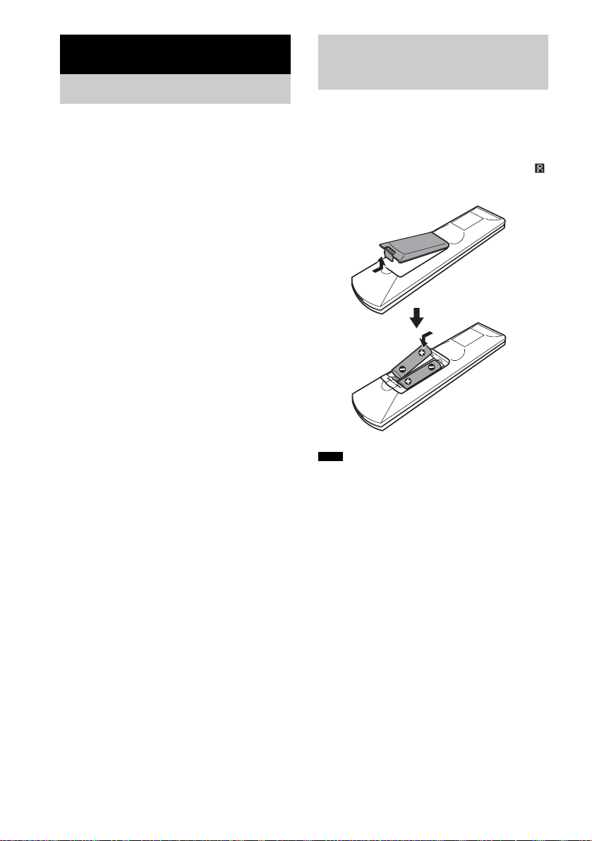
Inserting Batteries into the Remote
You can control the system using the supplied
remote. Insert two Size AA (R6) batteries by
matching the 3 and # ends on the batteries to
the markings inside the compartment. When
using the remote, point i t at the r emote sensor
on the system.
Note
• Do not leave the remote in an extreme ly hot or humid
place.
• Do not use a new battery with an old one.
• Do not drop any foreign object into the remote casing,
particularly when replacing the batteries.
• Do not expose the remote sensor to direct light from
the sun or lighting apparatus. Doing so may cause a
malfunction.
• If you do not intend to use the remote for an extended
period of time, remove the batteries to avoid possible
damage from battery leakage and corrosion.
12
US

Hookup Overview
Perform all connections and settings b y following Steps 1 to 7.
“Step 1: Speaker System Hookup” (page 14)
“Step 2: Antenna (Aerial) Hookup” (page 20)
“Step 3: TV Hookup” (page 21)
“Step 4: Other Component Hookup” (page 25)
“Step 5: Connecting the AC Power Cord (Mains Lead)” (page 27)
“Step 6: Turning off the Demonstration” (page 27)
“Step 7: Performing the Quick Setup” (page 28)
Video signal is sent to the TV, and is output from the TV screen; audio si gnals are processed by t his
system and output from the speakers of this system. You can also enjoy sound of other sources, suc h
as TV programs, in addition to DVDs or CDs.
Getting Started
13
US
Step 1: Speaker System Hookup
Connect the supplied speaker sy st em using the supp lied speaker cords by matching the colo rs of the
jacks to those of the cords. Do not connect any speakers other than those supplied with this system.
To obtain the best possible surround sound, specify the speak er par ameters (distance, level, etc.) on
page 75.
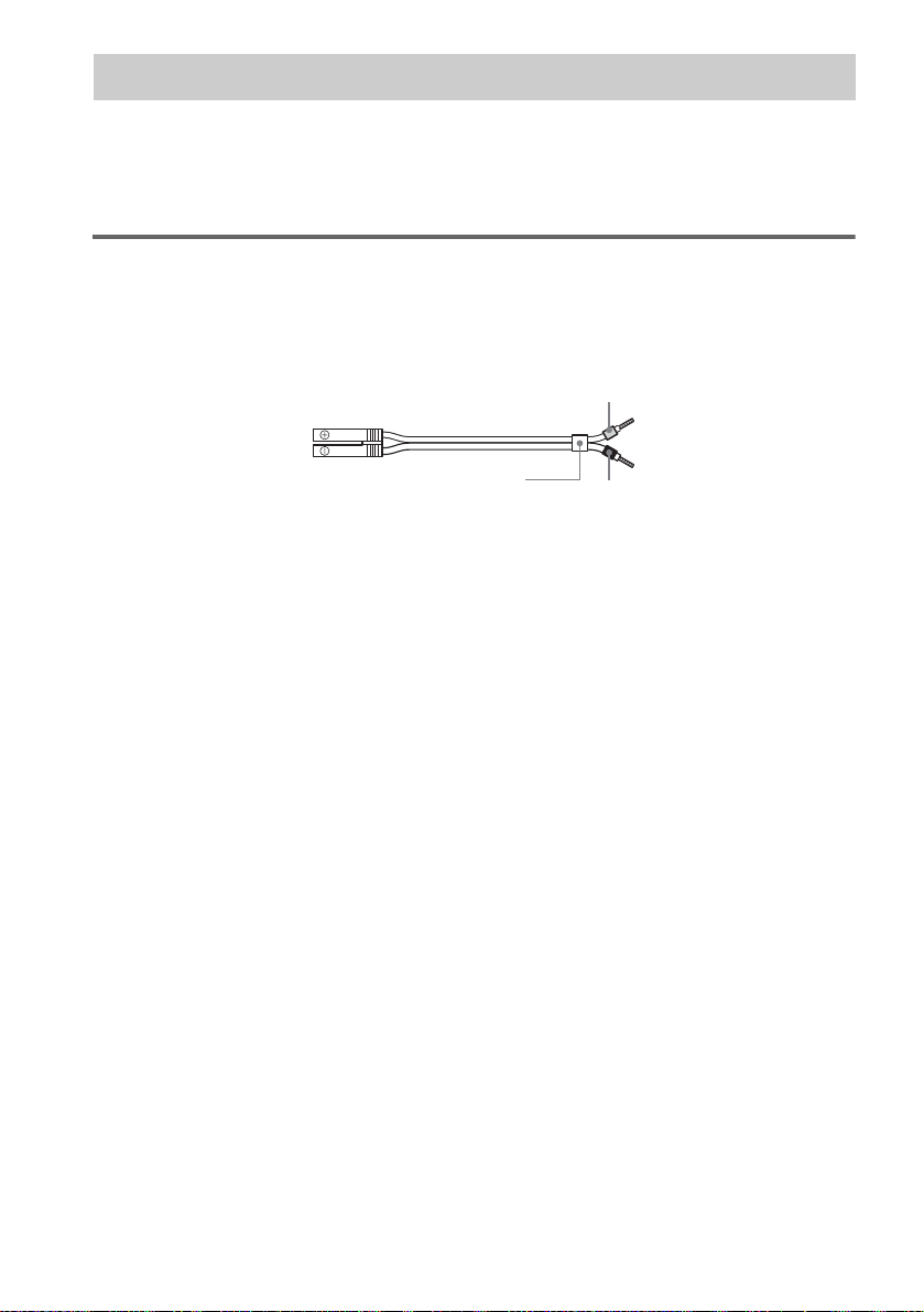
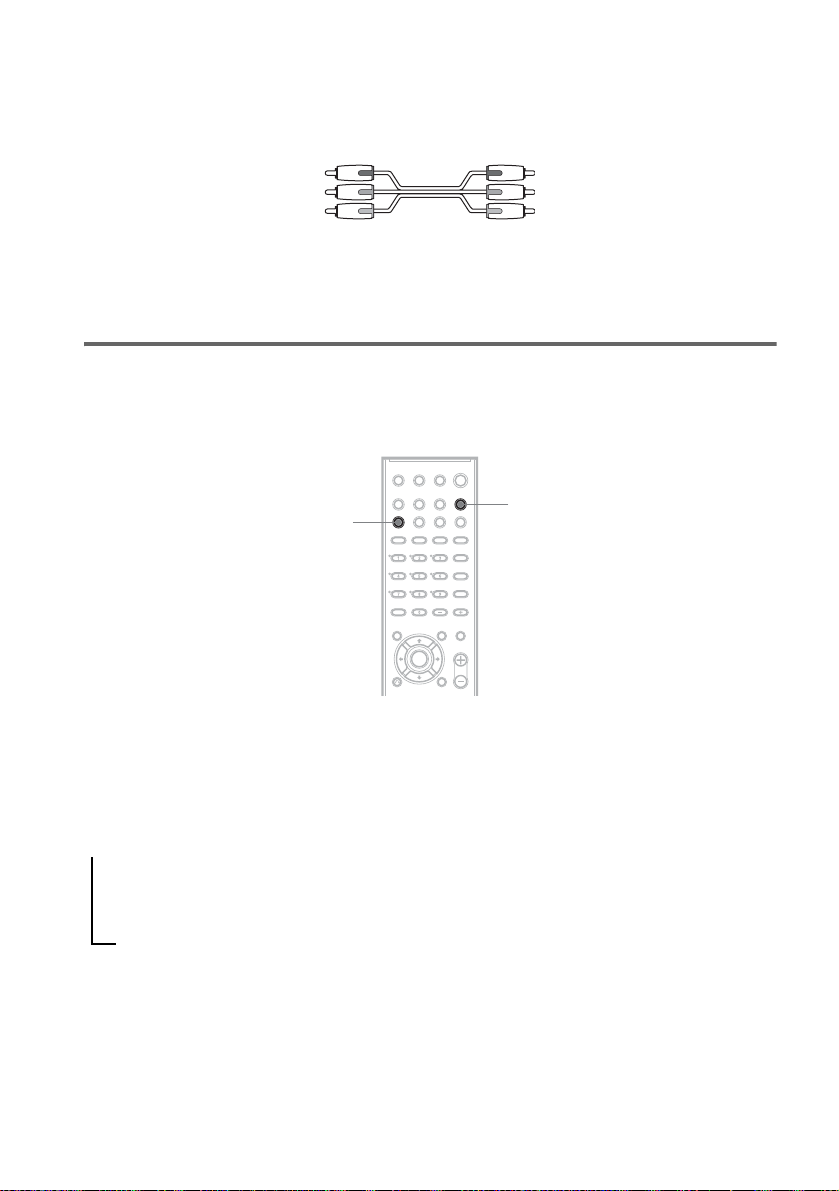
Required cords
Speaker cords
The connector and the color tube of the speaker cords are the same color as the label of the jacks to be
connected.
Gray
(+)
(–)
Color tube
(+)
(–)
Black
14
US
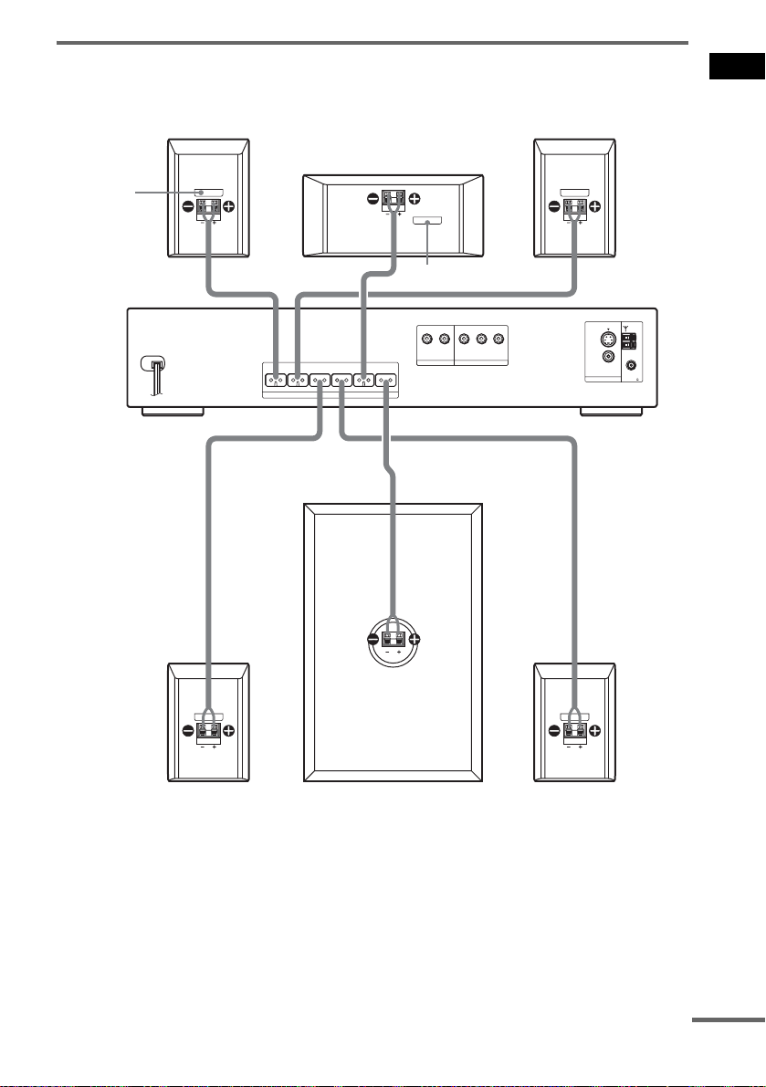
Connecting the speakers
DAV-DX170
Front speaker (R)
Color label
Getting Started
Front speaker (L)
Center speaker
Color label
Surround speaker (R)
FRONT R FRONT L SURR R SURR L CENTER WOOFER
SPEAKER
Subwoofer
AUDIO IN
VIDEO/SAT
R L
Y
PB/CBPR/C
DVD ONLY
COMPONENT VIDEO OUT
R
MONITOR OUT
Surround speaker (L)
VIDEOS (DVD ONLY)
VIDEO
AM
COAXIAL
FM
75
continued
15
US

DAV-DX250
Front speaker (R)
Bottom of the front
speaker
FRONT R FRONT L SURR R SURR L CENTER WOOFER
Center speaker
SPEAKER
Color label
AUDIO IN
R L
VIDEO/SAT
Front speaker (L)
Bottom of the front
speaker
Y
PB/CBPR/C
R
DVD ONLY
COMPONENT VIDEO OUT
VIDEOS (DVD ONLY)
VIDEO
MONITOR OUT
AM
COAXIAL
FM
75
Surround speaker (R)
Note
• Do not set the speakers in an inclined position.
US
16
Subwoofer
Surround speaker (L)

• Do not place the speakers in lo cations that are:
– Extremely hot or cold
– Dusty or dirty
– Very humid
– Subject to vibrations
– Subject to direct sunlight
• Use caution when placing t h e speakers and/or speaker stands (n o t supp lied) that are attached with th e s p eak ers on
a specially treated (waxed, oi l ed , po l is h ed , et c.) floor, as staining or discoloration may result.
• Do not use any type of abrasive pad, scouring powder, or solvent such as alcohol or benzin e.
• Do not lean or hang on the speaker, as the speaker may fall down.
To connect the speaker cords
Connect the speaker cords after bending the bare wire at the end of the insulation. This prevents the
speaker insulation from being inserted in the speaker terminal.
Getting Started
Note
• Do not catch the speaker cord insulation in the SPEAKER jack.
Avoiding short-circuiting the speakers
Short-circuiting of the speakers may damage the system. To prevent this, be sure to follow these
precautions when connecting the speakers. Make sure the bare wire of each speaker cord does not touch
another speaker terminal or the bare wire of another speaker cord.
Examples of poor conditions of the speaker cord
Stripped speaker cord is
touching another speaker
terminal.
Stripped cords are touching each
other due to excessive removal of
insulation.
continued
17
US

After connectin g al l the components, speakers, and AC power cor d (mains lead), output a test tone to
check that all the speakers are connected correctly. For details on outputting a test tone, see page 76.
If no sound is heard from a speaker while outputting a test tone, or a test tone is output from a speaker
other than the one currently displayed on the Setup Display, the speaker may be short-circuited. If this
happens, check the speaker connect i on again.
Note
• Be sure to match the sp eaker co rd to the appropr iate termi nal on the c omponent s: 3 to 3, and # to #. If the cords
are reversed, the sound will lack bass and may be distorted.
Installing the speakers on the wall
1 Prepare screws (not supplied) that are suitable for the hole on the back of each speaker.
See the illustrations below.
25 mm (1 inch)
4 mm (
5
/32 inch)
4.6 mm
(
10 mm
(
2 Fasten the screws to the wall.
The screws should protrude 5 to 7 mm (7/32 to 9/32 inch).
5 to 7 mm
7
(
/32 to 9/32 inch)
3 Hang the speakers on the screws.
4.6 mm
3
/16 inch)
(
10 mm
13
/32 inch)
(
Hole on the back of
the speaker
3
/16 inch)
13
/32 inch)
Hole on the back of
the speaker
18
US

Note
• Use screws that are suitable for the wall material and strength. As a plaster board wall is especially fragile, attach
the screws securely to a beam and fasten them to the wa ll . In st al l the speak ers on a vertical and flat wall where
reinforcement is applied.
• Contact a screw shop or installer regarding the wall material or screws to be used.
• Sony is not responsible for acci de n t or d amage caused by improper installation, insufficient wall strength or
improper screw insta lla tion, natural calamity, etc.
Getting Started
19
US

Step 2: Antenna (Aerial) Hookup
Connect the supplied AM/FM antennas (aerials) for listening to the radio.
AM loop antenna (aerial)
FM wire antenna (aerial)
Note
• To prevent noise pickup, keep the AM loop antenna (aerial) away from the system and other components.
• Be sure to fully exte nd the FM wire antenna ( aerial).
• After connecting the FM wire antenna (aerial), keep it as horizontal as possible.
Tip
• When you connect the supplied AM loop antenna (aerial), cord (A) or cord (B) can be connected to either terminal.
A
B
• If you have poor FM reception, use a 75-ohms coaxial cable (not supplied) to connect the system to an outdoor FM
antenna (aerial) as shown below .
System
Outdoor FM antenna (aerial)
US
20

Step 3: TV Hookup
First, perform the vi deo connection, and then audio connection .
With your TV’s audio output connected to this system, you can listen to TV sound through the system
speakers.
Connecting the video cords
Sends a played back DVD image to a TV.
Check the jacks of your TV, and choose the A, B or C connection. Picture quality improves in order
from A (stand ar d) to C (component).
To COMPONENT
VIDEO OUT
Getting Started
VIDEOS (DVD ONLY)
VIDEO
MONITOR OUT
AM
COAXIAL
FM
75
To
S VIDEO
FRONT R FRONT L SURR R SURR L CENTER WOOFER
SPEAKER
VIDEO/SAT
AUDIO IN
R L
Y
PB/CBPR/C
DVD ONLY
COMPONENT VIDEO OUT
R
To VIDEO
AB C
VIDEO
IN
TV TV with S VIDEO IN jack
A To connect to a TV with the VIDEO IN jacks
Connect the video co rd.
B To connect to a TV with the S VIDEO IN jack
Connect an S video cor d (not supplied). When using the S video jack in st ead of the video jacks, your
TV monitor must also be connected via an S video jack. S video signals are on a separate bus from the
video signals and wi l l not be output through the video jacks.
S VIDEO
IN
Y
PB/CB
PR/CR
TV with COMPONENT
VIDEO IN jacks
Yellow
continued
21
US
C To connect to a TV with the COMPONENT VIDEO IN jacks
Connect a co mponent vi deo co rd (not supp lie d). T o use th e COMP ONENT VIDEO O UT jac ks (Y, P B/
B, PR/CR) instead of the video jacks, your TV monitor must be equipped with via COMPONENT
C
VIDEO IN jacks (Y, P
connection and set the output channel of the system to progressive forma t ( page 22 ).
B/CB, PR/CR). If your TV accepts progressive format signals, you must use this
Green
Blue
Red
When connecting to a standard 4:3 screen TV
Depending on the di sc, the image may not fit your TV screen.
To change the aspect ratio, see page 72.
Does your TV accept progressive signals?
Progressive is the method for displaying TV images which reduces flickering, and sharpens the image.
To display using thi s m e thod, you need to connect to a TV that accepts pro gr essive signals.
PROGRESSIVE
“P AUTO” or “P VIDEO” appears in the front panel display w hen the system output s progressive
signals.
FUNCTION
1 Press FUNCTION repeatedly to select “DVD.”
2 Press PROGRESSIVE.
Each time you press PROGRESSIVE, the display changes as follows:
t P AUTO (PROGRESSIVE AUTO)
r
P VIDEO (PROGRESSIVE VIDEO)
r
INTERLACE
x P AUTO (PROGRESSIVE A UT O )
Select this setting when:
– your TV accepts progress iv e si gnals, and,
– the TV is connected to the COMPONENT VIDEO OUT jacks.
Normally select this under the above condition. This automaticall y detects the software type, and
selects the appropriate conversion method.
22
US

Note that the picture will not be clear or no picture will appear if you select these settings when
either of the above conditions is not met.
x P VIDEO (PROGRESSIVE VIDEO)
Select this setting when:
– your TV accepts progressive si gnals, and,
– the TV is connected to the COMPONENT VIDEO OUT jacks, and,
– you want to fix the conversio n m et hod to PROGRESSIVE VIDEO for video-based software.
Select this if the image is not clear when you select PROGRESSIVE AUTO.
Note that the picture will not be clear or no picture will appear if you select these settings when
either of the above conditions is not met.
x INTERLACE
Select this setting when:
– your TV does not accept progressive signals, or,
– your TV is connected to jacks other than the COMPONENT VIDEO OUT jacks (MONITOR
OUT (VIDEO/S VIDEO)).
About DVD software types and the conversion method
DVD software can be divided into 2 types: film-based software and video-based software.
Video-based software is derived from TV, such as dramas and sit-coms, and displays images at 30
frames/60 f ields per s econd. Fi lm-based software is derived f rom film an d display s images at 24 frames
per second. Some DVD software contains both video and film.
In order for these i mages to appear na tu ral on your screen w hen output in progre s si ve format, the
progressive signal s need to be converted to m at ch the type of DVD soft w are that you are watching.
Note
• When you play video-based software in prog ress ive signal format, sections of some types of ima ge s ma y app ear
unnatural due to the conversion process when output through the COMPONENT VIDEO OUT jacks. Even though
you set to “PROGRESSIVE AUTO” or “PROGRESSIVE VIDEO,” images from the MONITOR OUT (VIDEO or
S VIDEO) jack are unaffected as they are output in th e in t e rl ace format.
Getting Started
Connecting the audio cords
Outputs TV sound through the speakers of this system.
continued
23
US

TV
AUDIO
OUT
L
R
To VIDEO/SAT
(AUDIO IN)
VIDEOS (DVD ONLY)
VIDEO
MONITOR OUT
AM
COAXIAL
75
FM
FRONT R FRONT L SURR R SURR L CENTER WOOFER
SPEAKER
VIDEO/SAT
AUDIO IN
R L
Y
PB/CBPR/C
DVD ONLY
COMPONENT VIDEO OUT
R
To connect the AUDIO OUT jacks of a TV to the VIDEO/SAT (AUDIO IN)
jacks of this system
Connect a TV to the VIDEO/SAT (AUDIO IN) jacks using an audio cord (not supplied). When
connecting a cord, be sure to match the color-coded sleeves to the appropriate jacks on the components.
White (L/audio)
Red (R/audio)
Note
• Be sure to make connections sec ur el y to a void hum and noise. If using the VIDEO/SAT jac ks distorts the sound,
change the attenuat e se tt ing (page 66).
• If your TV does not have AUDIO OUT jacks, you cannot output the TV sound from the speakers of this system.
• If you connect a TV to the VIDEO/SAT (AUDIO IN) jacks, other components, such as a VCR, cannot be
connected.
Tip
• To listen to the TV sound, select the funct ion by pressing FUNCTION. For details, see page 56.
• When you want to output the TV sound or stereo sound of a 2 channel source from the 6 speakers, select the “Dolby
Pro Logic,” “Dolby Pro Logic II MOVIE,” or “Dolby Pro Logic II MUSIC ” sound f ield ( page 54).
• When you select the “NIGHT” sound field (page 54), the sound is output from the front spea kers only.
24
US

Step 4: Other Component Hookup
You can enjoy sound using the speake rs of this system by connecti ng the AUDIO OUT jacks of another
component. For video connection of oth er components, conn ect directly to the TV.
Note
• If you connect a TV to the VIDEO/SAT jacks in Step 3 (page 21), you cannot connect other components to the
system.
Connecting the system and the other component
Outputs the other component through the speakers of thi s system.
VCR, digital satellite receiver,
or PlayStation 2, etc.
AUDIO
OUT
L
R
To VIDEO/SAT
(AUDIO IN)
Getting Started
VIDEOS (DVD ONLY)
VIDEO
MONITOR OUT
AM
COAXIAL
75
FM
FRONT R FRONT L SURR R SURR L CENTER WOOFER
SPEAKER
AUDIO IN
VIDEO/SAT
R L
Y
PB/CBPR/C
DVD ONLY
COMPONENT VIDEO OUT
R
To connect the AUDIO OUT jacks of other component to the VIDEO/SAT
(AUDIO IN) jacks of this system
Connect the VCR or other components to the VIDEO/SAT (AUDIO IN) jacks using the audio cord (not
supplied). When connecting a cor d, b e s u r e to match the color- coded sleeves to th e appropriate jacks
on the components.
White (L/audio)
Red (R/audio)
Note
• Be sure to make connections securely to avoid hum and noise. If using the VIDEO/SAT jacks distorts the sound,
change the attenuate setting (page 66).
continued
25
US

Tip
• When you connect a VCR or digital sate ll ite receiv er to th e VIDEO/SAT ja cks of th is system, ch ange t he funct ion
by pressing FUNCTION repeatedly to select “VIDEO” or “SAT.” (When you select “ATT ON,” “SAT” appears in
the front panel display instead of “VIDEO.” (page 66))
26
US

Step 5: Connecting the AC Power Cord (Mains Lead)
Before connecting the AC power cord (mains
lead) of th is system to a wall outlet (mains),
connect the speakers to the system (page 14).
"/1
Step 6: Turning off the
Getting Started
Demonstration
"/1
AMP MENU
"/1
To turn on the system
Press "/1.
To turn off the system
Press "/1. The system enters stan dby mode.
While playing a disc, do not turn off the system
by pressing "/1. Doing so may cancel the menu
settings. When you turn off the system, first
press x to stop pl ayback and then pres s "/1.
X/x/c
ENTER
After connecting the AC power cor d (m ains
lead), the demonstration appears in the front
panel display. When you press "/1 on the
remote, the demonstration turns off.
Note
• When you press "/1 on the system, the demonstration
does not turn off.
• When you set the demonstr a tion mode in the AMP
menu to on, the demonstration does not turn off even
though you press "/1 on the rem ote. To turn off the
demonstration, set the demonstration mode to off,
then press "/1 on the remote.
Setting the demonstration mode on/off
1 Press AMP MENU.
2 Press X/x repeatedly until “DEMO”
appears in the front panel display, then
press ENTER or c.
3 Press X/x to select the setting.
• DEMO OFF: sets the demonstration mode
off.
• DEMO ON: sets the demonstration mode
on.
4 Press ENTER or AMP MENU.
The AMP menu turns off.
27
US
Step 7: Performing the Quick Setup
Follow the steps below to make the minimum
number of basic a dj ustments for using the
system.
To skip an adjustment, press >. To return to
the previous adjustment, press ..
The Setup Display for selecting the
language used in th e on-screen display
appears.
LANGUAGE SETUP
OSD:
MENU:
AUDIO:
SUBTITLE:
ENGLISH
ENGLISH
FRENCH
SPANISH
PORTUGUESE
"/1
CLEAR
X/x
ENTER
./>
1 Turn on the TV.
2 Press [/1.
Note
• Disconnect the headphone when you perform
the Quick Setup. You cannot operate steps after
8 with the headphone connected.
• Make sure that the function is set to “DVD.”
3 Switch the input selector on your TV so
that the signal from the system
appears on the TV screen.
[Press [ENT E R] to run QUIC K S E TUP.]
appears at the b ot tom of the screen. If this
message does not appear, display the Quick
Setup and perform ag ain (page 29).
Note
• When you pre ss CLEAR in message, the
message disappears. When you need to perform
the Quick Setup, see “T o recall the Quic k Setu p
display” (page 29).
4 Press ENTER without inserting a disc.
5 Press X/x to select a language.
The system displa ys the menu and sub title s
in the sele c ted langua ge.
Note
• The selectable language is dif f e r en t depending
on the area.
6 Press ENTER.
The Setup Display for selecting the aspect
ratio of the TV to be co nnected appears.
SCREEN SETUP
TV TYPE:
SCREEN SAVER:
BACKGROUND:
BLACK LEVEL:
BLACK LEVEL
4:3 OUTPUT:
4:3 LETTER BOX
4:3 LETTER BOX
4:3 PAN SCAN
(COMPONENT OUT)
16:9
OFF
:
FULL
7 Press X/x to select the setting that
matches your TV type.
x If you have a 4:3 standard TV
[4:3 LETTER BOX] or [4:3 PAN SCAN]
(page 72)
x If you have a wide-screen TV or a 4:3
standard TV with a wide-screen mode
[16:9] (page 72)
8 Press ENTER.
The Setup Display for selecting the speaker
distance appears.
9 Press X/x to select the front speaker
distance from the listening position,
then press ENTER.
You can set from 1.0 to 7. 0 me te rs (4 to 23
ft).
28
US

SPEAKER SETUP
SIZE:
DISTANCE:
LEVEL(FRONT):
LEVEL(SURROUND):
TEST TONE:
FRONT:
CENTER:
SURROUND:
OFF
3.0m
3.0m
3.0m
10Press X/x to select the center speaker
distance from the listening position,
then press ENTER.
You can set from 0.0 to 7.0 m eters (0 to 23
ft).
SPEAKER SETUP
SIZE:
DISTANCE:
LEVEL(FRONT):
LEVEL(SURROUND):
TEST TONE:
FRONT:
CENTER:
SURROUND:
Note
• The setting range changes depending on the
front speaker setting.
OFF
3.0m
3.0m
3.0m
11Press X/x to select the surround
speaker distance from the listening
position.
You can set from 0.0 to 7.0 m eters (0 to 23
ft).
Note
• If you want to change each setting, se e “Using the
Setup Display” (page 70).
To recall the Quick Setup display
1 Press DISPLAY when the system is
in stop mode.
The Control Menu a ppears.
2 Press X/x to select [SETUP],
then press ENTER.
The options for [SETU P] appear.
)
1 2 ( 2 7
)
BNR
1 8 ( 3 4
: :
QUICK
QUICK
CUSTOM
RESET
DVD VIDEO
3 Press X/x to select [QUICK], then press
ENTER.
The Quick Setup display appears.
Getting Started
SPEAKER SETUP
SIZE:
DISTANCE:
LEVEL(FRONT):
LEVEL(SURROUND):
TEST TONE:
FRONT:
CENTER:
SURROUND:
Note
OFF
• The setting range changes depending on the
front speaker setting.
12Press ENTER.
Quick Setup is finished. All connections
and setup operatio ns are complete.
To quit the Quick Setup
Press DISPLAY in any Step.
3.0m
3.0m
3.0m
29
US

Speaker Setup
Positioning the speakers
For the best possible surround sound, all the
speakers other than the subwoofer should be the
same distance from the listening position (A).
However, this system allows you to place the
center speaker up to 1.6 meters (5 ft) closer (B)
and the surroun d speakers up to 5.0 m eters (16
ft) closer (C) to the listening posi tio n.
The front speakers can be placed from 1.0 to
7.0 meters (4 to 23 ft) (A) from the listening
position.
Place speakers as illustrate d belo w.
If color irregularity is observed
again...
Place the speaker further away from t he TV set.
If howling occurs
Reposition the speakers or turn down the
volume on the system.
Note
• Do not place the center and surround speakers farther
away from the listening position than the front
speakers.
If you encounter color irregularity
on a nearby TV screen
The front and center speakers and the subwoofer
are magn e tically sh ielded to allow it to be
installed near a TV set. However, colo r
irregularities may still be observed on certai n
types of TV sets. As the surround speakers are
not magnetically shielded, we recommend that
you place the surround speakers slightly further
away from TV set.
If color irregularity is observed...
Turn off the TV set onc e, th en turn it on again
after 15 to 30 minutes.
US
30

Playing Discs
Playing Discs
When no disc is in the disc tray you
selected, “N O DISC” appears. Perform next
Step while “*DISC-1* (eg., 2-5)” flashes.
5 Press A.
6 Load a disc.
Place one disc on the tray, and then press A.
Playing Discs
"/1
Disc tray
DISC SKIP
REPEAT
X/x/c
ENTER
DISPLAY
DISC 1-5
Adjust the
volume
/
X
H
A
FUNCTION
Connect
headphone
"/1
FUNCTION
ALBUM –/+
MUTING
VOLUME +/–
./>
H
x
Depending on the DVD VIDEO or VIDEO CD,
some operations may be different or restricted.
Refer to the operat ion det ails su pplied with you r
disc.
1 Turn on your TV.
2 Switch the input selector on the TV to
this system.
3 Press "/1.
The system turns on.
Unless the system is set to “DVD,” press
FUNCTION to select “DVD.”
4 Press DISC 1-5.
Press the button of th e di sc number you
want.
When you play an 8 cm disc, place it on the
inner circle of the tray. Be careful that the disc
is not skewed on the inner circle of the tray.
To load other discs, press DISC 1-5 (that is
not loaded with a di sc) and A and load the
disc.
Note
• Do not forcibly press the disc tray clos ed wi th
your finger, as this may cause malfunction.
• Do not place more than two discs on the tray.
7 Press H.
The system starts pl ayback (continuous
play) of the disc w ho s e DISC indicator is
green.
To play back other discs, press DISC SKIP
on the remote or DISC 1-5 of the system.
Adjust the volume on the system.
Tip
• The DISC 1-5 indicators change color as follows:
– green: the disc is sele cted, or the disc is being
played back.
– off: there is no disc.
– orange: a disc is loaded in the disc stocker but not
selected.
– The indicator turns off if an unpla ya ble disc is
inserted.
• Depending on the disc, a menu may appear on the TV
screen. You can play the disc interactively by
following the instructions on the menu. (DVD:
page 36), (VIDEO CD: pa ge 37).
31
US

To save the power in standby
mode
Press "/1 while the system turns on. To cancel
standby mode, pres s "/1 once.
Additional operations
• You may not be able to use the Inst ant Replay or
Instant Advance function with some scenes.
About DVD 5-DISC changer
Sub Tray
Stocker
To Press
Stop x
Pause X
Resume play after pause X or H
Go to the next chapter,
track, or scene
Go back to the preceding
chapter, track, or scene
Mute the sound MUTING. To cancel
Change a disc while playing
another disc
Play the desired disc directly DISC 1-5 on the
Stop play and remove the
desired disc
Replay the previou s scene*
Briefly fast forward the
current scene*
Go to the next or previous
album*
*1DVD VIDEOs/DVD-RWs/DVD-Rs only.
*2DVD VIDEOs/DVD-RWs/DVD-Rs/DVD+RWs
only.
*3DATA CDs only.
Note
• If there is no disc i n t he s y stem , “NO DISC” appears
in the front panel display.
Tip
• The Instant Replay function is useful when you want
to review a scene or dialogue that you mi sse d.
• The Instant Advance function is useful when you
want to pass over a scene that you don’t want to
watch.
2
3
> (except for JPEG)
. (except for JPEG)
muting, press it again
or VOLUME + to
adjust the sound
volume.
DISC SKIP
system.
DISC 1-5 a nd A on the
system.
1
(instant
replay) during
playback.
(instant
advance) during
playback.
ALBUM + or – during
playback.
Disc
DISC 3
Main Tray
Playing unit
DISC 1
DISC 2
DISC 4
DISC 5
The disc changer consists of a playing unit and a
stocker which transpor ts the discs to t he disc slot
and the playing uni t.
For example, if you press DISC 3, the stocker
moves until the DISC 3 comes to th e position o f
the playin g unit and t hen move s the DISC 3 over
the playing unit.
Note
• Noise may come fr om the disc change r wh en
changing discs or turning the system on a nd of f.
However, this is just noise produced by the operation
of the internal mechanisms and does not indicate a
malfunction.
Resuming playback from the point where you stopped the disc (Resume Play)
When you stop the disc, the system remembers
the point where you pressed x and “RESUME”
appears in the front panel display. A s l ong as
you do not remove the disc, Resume Play will
work even if the system enters s tandby mode by
pressing "/1.
1 While playing a disc, press x to stop
playback.
“RESUME” appea rs in the front panel
display, so you can restart the disc from the
point where you stopped the disc.
If “RESUME” does not appear, Resume
Play is not available.
2 Press H.
32
US

The system starts playback from the point
where you stopped the disc in St ep 1.
Note
• If [MULTI-DISC RESUME] in [CUSTOM SETUP]
is set to [OFF] (page74), the resume point is cleared
when you change the function by pressing
FUNCTION.
• The point where you stopped playing may be cleared
when:
– you change the play mode.
– you change the settings on the Set up Display.
– you change the function by pressing FUNCTION.
– you disconnect the AC power cord (mains le a d).
• For DVD-RWs in VR mode, CDs, and DATA CDs,
the system remembers the resume playback point for
the current disc.
The resume point is cleared when:
– you eject the disc.
– the system enters standby mode (DATA CD only).
• Resume Play does not work during Program Play and
Shuffle Play.
• This function may not work with som e dis cs .
• Depending on where you stop the disc, the syst em
may not resume playback fro m ex act ly the same
point.
Tip
• To play from the beginning of the disc, press x twice,
then press H.
To enjoy a disc that is played
before by resume playback
(Multi-disc Resume)
(DVD VIDEO, VIDEO CD only)
This system stores the po i n t w here you stoppe d
the disc for up to 40 discs and resumes playback
the next time you inser t the same disc. If you
store a resume pl ayback point for the 41st disc,
the resume p la y back point for the first disc is
deleted.
To activate this function, set [MULTI-DISC
RESUME] in [CUSTOM SETUP] to [ON]. For
details, see “[MULTI-DISC RESUME] (DVD
VIDEO/VIDEO CD only)” (page 74).
Note
• If [MULTI-DISC RESUME] in [CUSTOM SETUP]
is set to [ON] (page 74) and you playback a reco rded
disc such as DVD-RW, the system may playback
other recorded discs from the same resume point. To
play from the beginning, press x twice and then press
H.
Creating your own program (Program Play)
(VIDEO CD, CD only)
You can play the co nt ents of a disc in the order
you want by ar rangi ng t he orde r of th e tr acks o n
the disc to create your own program. You can
program up to 99 tracks.
Note
• You can program the track on the current disc only.
1 Press DISPLAY.
The Control Menu a ppears.
2 Press X/x to select
[PROGRAM], then press ENTER.
The options for [PROGRAM] appear.
T
OFF
OFF
SET
ON
6 (14)
2 : 5 0
PLAY
CD
3 Press X/x to select [SET t], then
press ENTER.
[TRACK] is displayed when you play a
VIDEO CD or CD.
PROGRAM
ALL CLEAR
1. TRACK
2. TRACK
3. TRACK
4. TRACK
5. TRACK
6. TRACK
7. TRACK
Tracks recorded
on a disc
– –
– –
– –
– –
– –
– –
0:00:00
T
– –
01
02
03
04
05
06
Total time of the
programmed tracks
4 Press c.
The cursor moves to the track row [T] (in
this case, [01]).
continued
33
Playing Discs
US

PROGRAM
ALL CLEAR
1. TRACK
2. TRACK
3. TRACK
4. TRACK
5. TRACK
6. TRACK
7. TRACK
– –
– –
– –
– –
– –
– –
– –
0:00:00
T
– –
01
02
03
04
05
06
5 Select the track you want to program.
For example, select track [02].
Press X/x to select [02] under [T], then
press ENTER.
Selected track
– –
– –
– –
– –
– –
– –
0:15:30
T
– –
01
02
03
04
05
06
PROGRAM
ALL CLEAR
1. TRACK 0 2
2. TRACK
3. TRACK
4. TRACK
5. TRACK
6. TRACK
7. TRACK
Total time of the programmed tracks
6 To program other tracks, repeat steps 4
to 5.
The programmed tracks are displayed in the
selected order.
7 Press H to start Program Play.
Program Play starts .
When the program ends, you can restart the
same program ag ai n by pressing H.
To return to normal play
Press CLEAR, or select [OFF] in Step 2. To play
the same program again, select [ON] in Step 3
and press ENTER.
To turn off the Control Menu
Press DISPLAY repeatedly until the Control
Menu is turned of f.
To change or cancel a program
1 Follow steps 1 to 3 of “Creating your own
program (Program Play).”
2 Select the program number of the track you
want to change or cancel using X/x. If you
want to delete the track from the program,
press CLEAR.
3 Follow Step 5 for new programming. To
cancel a program, select [--] under [T], then
press ENTER.
To cancel all of the tracks in the
programmed order
1 Follow steps 1 to 3 of “Creating your own
program (Program Play).”
2 Press X and select [ALL CLEAR].
3 Press ENTER.
Tip
• You can perform Shuffle Play or Repeat Play of
programmed tracks. During Program Play, follow the
steps of Shuffle Play (page 34) or Repeat Play
(page 35).
Note
• All Discs Repeat is automatically changed into
Program Repeat when you set to program play mode.
You can only program the contents of the current
disc.
• When you change the disc by pressing DISC SKIP or
DISC 1-5, programmed tracks are canceled.
• You cannot use this function with VIDEO CDs and
Super VCDs with PBC playback.
Playing in random order (Shuffle Play)
(VIDEO CD, CD only)
You can have the system “shuffle” tracks.
Subsequent “shuffling” may produce a different
playing order.
Note
• You can shuffle the track on the current disc only.
1 Press DISPLAY during playback.
The Control Menu appears.
2 Press X/x to select [SHUFFLE],
then press ENTER.
The options for [SH U FFLE] appear.
34
US

T
OFF
OFF
TRACK
6 (14)
2 : 5 0
PLAY
CD
6 (14)
T
2 : 5 0
OFF
OFF
ALL DISCS
ONE DISC
TRACK
PLAY
CD
Playing Discs
3 Press X/x to select the item to be
shuffled.
x When playing a VIDEO CD or CD
• [TRACK]: shu ff l es tracks on the disc.
x When Program Play is activated
• [ON]: shuffl es tra cks sel ected in Pro gram
Play.
4 Press ENTER.
Shuffle Play starts.
To return to normal play
Press CLEAR, or select [OFF] in Step 2.
To turn off the Control Menu
Press DISPLAY repeatedly until the Control
Menu is tu rned off.
Tip
• You can set Shuffle Play while the system is stopped.
After selecting the [SHUFFLE] option, press H.
Shuffle Play starts.
Note
• You cannot use this function with VIDEO CDs an d
Super VCDs with PBC playback.
Playing repeatedly (Repeat Play)
You can pla y all of t he titl es, tr acks or a lbums on
a disc or a single title , ch apter, track, or albu m
repeatedly.
You can use a combination of Shuffle or
Program Play modes.
1 Press DISPLAY during playback.
The Control Menu ap pears.
2 Press X/x to select [REPEAT],
then press ENTER.
The options for [REPEAT] appear.
3 Press X/x to select the item to be
repeated.
The default setting is underlined.
x When playing a DVD VIDEO or DVDRW
•[OFF]: does not play repeatedly.
• [ALL DISCS]: r epeats all o f the discs.
• [ONE DISC]: repeats all of the titles on
the current dis c. (When playing a DV D RW in VR mode, [ONE DISC] repeats all
of the titles of the selected type.)
• [TITLE]: repeats the current title on a
disc.
• [CHAPTER]: repeats the current chapter.
x When playing a VIDEO CD or CD
•[OFF]: does not play repeatedly.
• [ALL DISCS]: r epeats all o f the discs.
• [ONE DISC]: repeats all of the tracks on
the current dis c.
• [TRACK]: repeat s the current track.
x When playing a DATA CD
•[OFF]: does not play repeatedly.
• [ALL DISCS]: r epeats all o f the discs.
• [ONE DISC]: repeats all of the albums on
the current dis c.
• [ALBUM]: repeats the current album.
• [TRACK] (MP3 audio tracks only):
repeats the current track.
4 Press ENTER.
The item is selected.
To return to norma l pl ay, pres s C LEAR, or
select [OFF] in Step 2.
To turn off the Control Menu
Press DISPLAY repeatedly until the Control
Menu is turned off.
continued
35
US

Tip
• You can set Repeat Play while the system is stopped.
After selecting the [REPEAT] option, press H.
Repeat Play starts.
• You can quickly display the [REPEAT] sta tus by
pressing REPEAT. Each time you press REPEAT,
the [REPEAT] option changes.
Note
• You cannot use this function with VIDEO CDs and
Super VCDs with PBC playback.
• When playing a DATA CD which contains MP3
audio track and JPEG image files, and their pla ying
time are not the same, the audio sound will not match
the image.
• When [MODE (MP3, JPEG)] is set to [IMAGE
(JPEG)] (page 42), you cannot select [TRACK].
Using the DVD’s Menu
A DVD is divided into a lot of sections, which
make up a picture or m usic feature. These
sections are calle d “titles.” When you pl ay a
DVD which contains several titles, you can
select the title you want using TOP MENU.
When you play DV D s t hat al low you to select
items such as the language for the subtitles and
the language for th e s ound, select these ite m s
using MENU.
Number
buttons
TOP
MENU
C/X/x/c
ENTER
MENU
36
1 Press TOP MENU or MENU.
The disc’s menu appears on the TV sc reen.
The contents of the me nu va ry fro m di sc to
disc.
2 Press C/X/x/c or the numbe r buttons to
select the item you want to play or
change.
3 Press ENTER.
US

Selecting [ORIGINAL] or
Playing VIDEO CDs with
[PLAY LIST] on a DVD-RW
Some DVD-RWs in VR (Video Recording)
mode have two types of titles for playback:
originally recorded titles ([ORIGINAL]) and
titles that can be created on recordable DVD
players for edi ti ng ([PLAY LIS T ]). You can
select the type of title t o be played.
X/x
ENTER
DISPLAY
1 Press DISPLAY when the system is
in stop mode.
The Control Menu ap pears.
2 Press X/x to select [ORIGINAL/
PLAY LIST], then press ENTER.
The options for [ORIGINAL/PLAY LIST]
appear.
)
1 ( 4 4
(
3
2 8
T
1 : 3 0 : 5 0
PLAY LIST
PLAY LIST
ORIGINAL
)
DVD-RW
3 Press X/x to select a setting.
• [PLAY LIST]: plays the titles created
from [ORIGINAL] for editing.
• [ORIGINAL]: plays the titles originally
recorded.
4 Press ENTER.
PBC Functions (Ver.2.0)
(PBC Playback)
With PBC (Playback Cont r ol ) f unc tions, you
can enjoy simple interactive operations, search
functions, an d other such opera t i ons.
PBC playback allow s you to play VIDEO CDs
interactively by following the me nu on the TV
screen.
Number
buttons
ENTER
1 Start playing a VIDEO CD with PBC
functions.
The menu for your selection appears.
2 Select the item number you want by the
number buttons.
3 Press ENTER.
4 Follow the instructions in the menu for
interactive operations.
Refer to the operation details s upplied wit h
the disc, as the operating procedure may
differ depending on th e V I D EO CD .
To go back to the menu
Press O RETURN.
Note
• Depending on the VIDEO CD, the menu does not
appear in Ste p 1 .
Playing Discs
continued
37
US

• Dependin g o n the VIDEO CD, [Press ENTER] in
Step 3 may appear as [Press SELECT] in the
instructions supplied with the disc. In this case, press
H.
Tip
• To play without using PBC, press ./> or the
number buttons while the system is stopped to select
a track, then press H or ENTER.
[Play without PBC] appears on the TV screen and the
system starts continuous play. Yo u cannot play still
pictures such as a menu . T o ret ur n t o PBC pl ay b ack ,
press x twice, then press H.
About MP3 Audio Tracks and JPEG Image Files
What is MP3/JPEG?
MP3 is audio comp ression technology that
satisfies the ISO/MPEG regulations. JPEG is
image compression technology.
Discs that the system can play
You can play back DATA CDs (CD-ROMs/CDRs/CD-RWs) recorded in MP3 (MPEG1 Audio
Layer 3) and JPEG format. However, the discs
must be recorded according to ISO 9660 Level
1, Level 2 or Joliet format for the system to
recognize the tracks (or files). You can also play
discs recorded in Multi Session.
See the instructions supplied with the CD-R/
CD-RW drives and the recording software (not
supplied) for details on the recording format.
About the multi-session disc
If MP3 audio track s or JPEG image files are
recorded in the first s ession, the system will also
play MP3 audio tracks or JPEG image files i n
other sessions. If audio tracks and ima ges in
audio CD format or video CD format are
recorded in the first session, only the first
session will be played back.
Note
• The system may not be able to play some DATA CDs
created in the Packet Write format. In this case, you
cannot view the JPEG images recorded.
38
MP3 audio track or JPEG image file that the syst em can play
The system can play the MP3 audio tracks or
JPEG image files:
• which have the ex tens ion “. MP3” (MP 3 audi o
track) or “.JPG”/“.JPEG” (JPEG image file)
• which conform to the DCF* image file format
US

* “Design rule for Camera File system”: Image
standards for digital cam era s regulated by Japan
Electronics and Information Technology Industries
Association (JEITA).
Note
• The system will play any data with the
extension “.MP3,” “.JPG,” or “.JPEG” even if
they are not in MP3 or JP EG format. Playing
this data may generate a loud noise which
could damage your spe aker system.
• The system does not conform to audio in
MP3PRO format.
Playback order of MP3 audio tracks or JPEG image files
The playback order of MP3 audio tracks o r
JPEG image files recorded on a DATA CD is as
follows:
x Structure of disc contents
Tree 1 Tree 2 Tree 3 Tree 4 Tree 5
ROOT
currently selected album take priority over the
next album in the same tree. (Example: C
contains D so 4 is played before 5.)
When you press MENU and the list of albu m
names appear s ( page 40), the album names are
arrange d in the follo wing order:
A t B t C t D t F t G. Albums
that do not contai n tracks (or files) (such as
album E) do not appea r in the lis t.
Tip
• If you add number s (01, 02 , 03, etc.) to the fron t of th e
track/file names when you store the tracks (or files) in
a disc, the tracks an d files wil l be played in that o rder.
• Since a disc with ma ny tr ees takes longer to start
playback, it is recomme n de d that you create albums
with no more than tw o tr ees.
Note
• Depending on the software you use to create the
DATA CD, the playback order may differ from the
illustration.
• The playback order above ma y not be app lic a ble if
there are more than 200 albu ms and 300 fi le s in each
album.
• The system can recognize up to 200 albums (the
system will count just albums, including albums that
do not contain MP3 audio tracks and JPEG image
files). The system will not play any albums beyond
the 200th album.
• The system may take longer time to playback, when
progressing to the following albu m or jum p to othe r
album.
• Some type of JPEG files cannot be played.
Playing Discs
Track (MP3 audio) or
Album
File (JPEG image)
When you insert a DATA CD and press H, the
numbered tracks (or fi l es) are played
sequentially, from 1 through 7. Any subalbums/tracks (or files) contained within a
39
US

Playing DATA CDs wi th MP3 Audio Track and JPEG Image Files
(
3 0
)
3
ROCK BEST HIT
KARAOKE
MY FAVOURITE SONG
R&B
JAZZ
CLASSIC
SALSA OF CUBA
BOSSA NOVA
MP3 audio tracks and JPEG image files
recorded on DATA CDs (CD-ROMs/CD-Rs/
CD-RWs) can be played on this syst em.
PICTURE
NAVI
MENU
C/X/x/c
ENTER
H
Tip
• You can view the disc inform a tion while playing
MP3 audio tracks and JPEG image fi le s (p ag e 49).
• You can select Repeat P lay while playing MP3 au dio
tracks and JPEG image files (page 35) and [AUDIO]
while playing an MP3 audio track (page 52).
x
Selecting an album
1 Load a DATA CD.
The list of albums recorded on the DATA
CD appears. When an album is being
played, its title is shaded.
You can turn the al bum list on and off by
pressing MENU.
2 Press X/x to select the album you want
and press H.
The system starts playing the selected
album.
To stop playback
Press x.
To play the next or previous MP3
audio track
Press ./>. Note that you can select the
next album by continuing to press > after the
last track on the first album, but that you cannot
return to the prev ious album by pressi ng ..
To return to the previous album, select the
album from the album list.
To play the next or previous JPEG
image file
Press C/c when the Control Menu is not
displayed. Note that you can select the next
album by continuing to press c after the last
image on the first album, but that you cann ot
return to the prev ious album by pressi ng C. To
return to the previous album, select the album
from the album list.
To turn off the display
Press MENU.
Selecting an MP3 audio track
1 Load a DATA CD.
The albums recorded on the DATA C D
appear. When an album is being played, its
title is shaded.
2 Press X/x to select an album and press
ENTER.
40
US

The list of tracks contained in the album
appears.
M Y FAVOURITE SONG
1 ( 2 5 6
WALTZ FOR DEBBY
MY ROMANCE
MILES TONES
MY FUNNY VALENTINE
AUTUM LEAVES
ALL BLUES
SOMEDAY MY PRINCE W...
)
3 Press X/x to select a track and press
ENTER.
The selected track st arts playing. You can
turn the track list off by pressing MENU.
Pressing MENU again will display the
album list.
To stop playback
Press x.
To play the next or previous MP3
audio track
Press ./>. Note that you can select the
next album by continuing to press > after the
last track on the first album, but that you cannot
return to the previous album by pressing ..
To return to the previous album, select the
album from the album list.
To return to the previous display
Press O RETURN.
To turn off the display
Press MENU.
Selecting a JPEG image file
1 Load a DATA CD.
The albums recorded on the DATA CD
appear. When an album is being played, its
title is shad ed .
2 Press X/x to select an album and press
PICTURE NAVI.
Images of files in the album appear in 16
subscreens.
1234
5678
Playing Discs
9101112
13 14 15 16
3 Press C/X/x/c to select the image you
want to view and press ENTER.
To play the next or previous JPEG
image file
Press C/c when the Con trol Menu i s n ot
displayed. Note that you can select the next
album by continui ng to press c after the last
image on the first album, but that you cannot
return to the previous album by pressing C. To
return to the previous album, select the album
from the album lis t.
To rotate a JPEG image
When a JPEG image file is displayed on the
screen, you can rotate the image by 90 degrees.
Press X/x while viewing an image. Each time
you press X, the image r otates counte rclockwise
by 90 degrees.
Example of whe n you press X once:
Rotating direction
continued
41
US

Press CLEAR to return to normal view.
Note
• Nothing happens when you press C while playing the
first image file of th e album.
• If you press C/c to go to the next or previous image,
the “Rotating a JPEG image” function is canceled.
• The slide show stops when you press X/x.
Playing Audio Tracks and Images as a Slide Show with Sound
To stop playback
Press x.
Tip
• A scroll box is displayed at the right side of th e
screen. To display the additiona l image files, select
the bottom image and press x. To return to the
previous image, select the top image and press X.
• You can also change the slide show du rat ion
(page 43) and eff
image file.
ect
(page 44) while playing JPEG
You can play a slide show with sound by f ir s t
placing both MP3 a nd J P EG f iles in the same
album on a DA TA CD. When yo u pl ay bac k the
DATA CD, select [AUTO] mode as explained
below.
X/x
ENTER
H
MENU
DISPLAY
1 Load a DATA CD.
2 Press DISPLAY.
The Control Menu appears.
3 Press X/x to select [MODE
(MP3, JPEG)], then press ENTER.
The options for [MODE (MP3, JPEG)]
appear.
42
)
1 2 ( 2 7
)
1 8 ( 3 4
T
1 : 3 2 : 5 5
AUTO
AUTO
AUDIO (MP3)
IMAGE (JPEG)
DATA CD
MP3
4 Press X/x to select the setting you
want and press ENTER.
The default setting is underlined.
US

•[AUTO]: plays both the JPEG image files
and MP3 audio tracks in the same album
as a slide show.
• [AUDIO (MP3)]: plays only MP3 audio
tracks continuousl y.
• [IMAGE (JPEG)]: plays only JPEG
image files as a slide show.
5 Press MENU.
The list of albums re corded on the DATA
CD appears.
6 Press X/x to select the album you want
and press H.
The system starts playing the selected
album.
You can turn the album list on and off by
pressing MENU repeatedly.
Tip
• You can also change the slide show durati on
(page 43) and effect (pag e 44) while playing JPEG
image files.
• If you want to play a slide show to the same audio
track, set the track to Repeat Play (page 35).
• When you select [AUTO], the system can recogniz e
up to 300 MP3 tracks and 300 JPEG files in a single
album. When you select [AUDIO (MP3)] or [IMAGE
(JPEG)], the system can recognize up to 600 MP3 and
600 JPEG files in a single album. A maximum of 200
albums can be recognized regardless of the selected
mode.
Note
• You cannot playback JPEG files and MP3 tracks at
the same time if they are not contained in the same
album.
• When the JPEG image file’s playbac k dur a tion is
longer than the MP3 audio track, the image slide
show continues without sound.
• When the MP3 audio track is longer tha n the JPEG
image file’s playback duration, the audio track
continues with no slide show.
• If there are no MP3 audio tracks and JPEG image
files in the DATA CD, the [No audio data] and [No
image data] messages appear on the screen.
• If you set [MODE (MP3, JPEG)] to [IMAGE
(JPEG)] on a disc that contains MP3 tra ck s only or
[AUDIO (MP3)] on a disc that contains JPEG files
only, you may not able to change the [MODE (MP3,
JPEG)] setting.
• PICTURE NAVI does not work when [AUDIO
(MP3)] is selected.
• If you play large MP3 track data and JP EG image
data at the same time, the so und ma y skip. It is
recommended that you set the MP3 bit rate to 128
kbps or lower when creating the file. If the sound still
skips, then reduce the si ze of the JPEG file.
Specifying the slide show duration
(JPEG only)
When you play JPEG image files using slide
show, you can spe cify the duration for sl ides to
appear on the screen.
1 Press DISPLAY twice.
The Control Menu for JPEG appears.
2 Press X/x to select
[INTERVAL], then press ENTER.
The options for [INTERVAL] appear.
12)
3 (
4)
1(
10 / 29 / 2 004
NORMAL
NORMAL
FAST
SLOW1
SLOW2
DATA CD
JPEG
3 Press X/x to select the setting you
want.
The default setting is underlined.
• [NORMAL]
: sets the duration to about 6
to 9 seconds. (Images that are four million
pixels or more will lengthen t he durati on.)
• [FAST]: sets the duration shorter than
[NORMAL].
• [SLOW1]: Sets the duration longer than
[NORMAL].
• [SLOW2]: Sets the duration longer than
[SLOW1].
4 Press ENTER.
The selected setting takes effect.
Note
• Some JPEG files may take longe r to display than
others, which may make the duration seems longer
that the option you selected. Especia ll y pro g res sive
JPEG files or JPEG files of 3,000,000 pixels or more.
Playing Discs
43
US

Selecting an effect for image files in the slide show
(JPEG only)
When you play a JPEG image file, you can
select the effect to be used when viewing the
slide show.
1 Press DISPLAY twice.
The Control Menu for JPEG appears.
2 Press X/x to select [EFFECT],
then press ENTER.
The options for [EFFECT] appear.
12)
3 (
4)
1(
1 0 / 2 3 / 2 0 0 4
MODE1
MODE1
MODE2
MODE3
MODE4
MODE5
OFF
DATA CD
JPEG
3 Press X/x to select the setting you
want.
The default setting is underlined.
• [MODE1]
: The image sweeps in from top
to bottom.
• [MODE2]: The image stretches out from
left to right of the screen.
• [MODE3]: The image stretches out from
the center of the screen.
• [MODE4]: The images randomly cycle
through the eff ects.
• [MODE5]: The next image slides over the
previous image.
• [OFF]: Turns off this function.
4 Press ENTER.
The selected se tti n g takes effect.
Adjusting the Delay Between the Picture and Sound
(A/V SYNC)
When the sound doe s not match the pictures on
the screen, you can adjust the delay between the
picture and sound.
X/x
ENTER
DISPLAY
1 Press DISPLAY in stop mode.
The Control Menu appears.
2 Press X/x to select [A/V
SYNC], then press ENTER.
The options for [A/V SYNC] appear.
)
1 ( 4 4
3
T
OFF
OFF
ON
(
)
2 8
1 : 3 0 : 5 0
DVD-RW
3 Press X/x to select the setting.
• [OFF]: does not adjust.
• [ON]: adjust s the difference betw een
picture and so und.
Note
• Depending on the input stream, this function may not
be effective.
44
US

Searching for a Particular Point on a Disc
(Scan, Slow-motion Play, Freeze
Frame)
Playback direction
×2B t 1M t 2M t 3M
3M (DVD VIDEO/DVD-RW/VIDEO CD only)
×2B (DVD VIDEO/CD only)
Opposite direction
Playing Discs
You can quickly locate a parti cular point on a
disc by monitoring the picture or playi ng back
slowly.
/
H
Note
• Depending on the DVD/VIDEO CD, you may not be
able to do some of the operations des c ribed.
SLOW /
m/M
X
Locating a point quickly by playing a disc in fast forw ar d or fast reverse (Scan)
(except for JPEG)
Press m or M while playing a disc.
When you find the point you want, press H to
return to normal speed. Each time you press
m or M during scan, the playback speed
changes. With each press the indication changes
as shown below. Ac tu al speeds may differ wit h
some discs.
×2b t 1m t 2m t 3m
3m (DVD VIDEO/DVD-RW/VIDEO CD only)
×2b (DVD VIDEO only)
The “
×2B”/“×2b” playback speed is about
twice the normal speed. The “3M”/“3m”
playback speed is faster than the “2M”/
“2m” and the “2M”/“2m” playback speed
is faster than “1M”/“1m.”
Watching frame by frame (Slow-motion Play)
(DVD, DVD-RW, VIDEO CD only)
Press m or M when the system is in
pause mode. To return to the normal playback
speed, pres s H. Each time you press m or
M during Slow-motion Play, the playback
speed changes. Two speeds are available. With
each press the indication changes as follows:
Playback direction
2 y 1
Opposite direction (DVD VIDEO only)
2 y 1
The “2 ”/“2 ” playback speed is slower
than “1 ”/“1 .”
Playing one frame at a time (Freeze Fram e)
(except for CD and JPEG)
When the system i s i n th e pause mode, press
(step) to go to the next frame. Press
(step) to go to the pre ceding frame
(DVD VIDEO/DVD-RW only). To return to
normal playbac k, press H.
continued
45
US

Note
• You cannot search for a still picture on a DVD-RW in
VR mode.
Searching for a T i tle/ Chapter/Track/Scene, etc.
You can search a DVD by title or chapter, and
you can search a VIDEO CD/CD/DATA CD by
track, index, or scene. As titles and tracks ar e
assigned unique numbers on the disc, yo u can
select the desired one by entering its number. Or,
you can search for a scene using the time code.
Number
buttons
CLEAR
X/x
ENTER
DISPLAY
46
1 Press DISPLAY. (When playing a
DATA CD with JPEG image files, press
DISPLAY twice.)
The Control Menu appears.
2 Press X/x to select the search method.
x When playing a DVD VIDEO/DVD-RW
[TITLE]
[CHAPTER]
[TIME/TEXT]
Select [TIME/TEX T] t o search for a
starting point by inputting the time code.
x When playing a VIDEO CD/Super
VCD without PBC Playback
[TRACK]
[INDEX]
US

x When playing a VIDEO CD/Super
VCD with PBC Playback
[SCENE]
x When playing a CD
[TRACK]
x When playing a DATA CD (MP3
audio)
[ALBUM]
[TRACK]
x When playing a DATA CD (JPEG file)
[ALBUM]
[FILE]
Example: when you select
[CHAPTER]
[** (**)] is selected (** refers to a number).
The number in parentheses indic ates the
total number of titles, chapters, tracks,
indexes, scenes, al bums or files.
)
1 2 ( 2 7
)
1 8 ( 3 4
T
1 : 3 2 : 5 5
Selected row
DVD VIDEO
5 Press ENTER.
The system starts playback from the
selected number.
To search for a scene using the
time code (DVD VIDEO only)
1 In Step 2, select [TIME/TEXT].
[T **:**:**] (playing time o f the current title)
is selected.
2 Press ENTER .
[T **:**:**] ch anges to [T --:--:--].
3 Input the time code using the number
buttons, then press ENTER.
For example, to find the scene at 2 hour s, 10
minutes, and 20 seconds after the beginning,
just enter [2:10:20].
Tip
• When the Control Menu display is turned off, you can
search for a chapter (DVD VIDEO/DVD-RW) or
track (CD) by pressing the number button s and
ENTER.
Note
• You cannot search for a scene on a DVD+RW using
the time code.
• The title, chapter or track number displayed is the
same number recorded on the disc .
Playing Discs
3 Press ENTER.
[** (**)] chan ges to [– – (**)].
)
1 2 ( 2 7
)
T
( 3 4
1 : 3 2 : 5 5
DVD VIDEO
4 Press X/x or the number buttons to
select the title, chapter, track, index,
scene, etc., number you want to search
for.
If you make a mistake
Cancel the number by pressing CLEAR,
then select another number.
47
US

Searching by Scene
(Picture Navigation)
You can divide the scr een i nto 9 su bscr eens and
find the desired scene quickly.
PICTURE
NAVI
C/X/x/c
ENTER
DISPLAY
1 Press PICTURE NAVI during playback.
The following display appears.
1
4
7
2
5
8
3
6
9
4 Press C/X/x/c to select a title, chapter,
or track, and press ENTER.
Playback starts fro m the selected scene.
To return to normal play during
setting
Press O RETURN or DISPLAY.
Tip
• If there are more than 9 titles, chapters, or tracks, V is
displayed at the bottom ri ght of the screen.
To display the add it ional titles, chap ters, or tracks,
select the botto m scene s and pres s x. To return to the
previous scene, select the top scenes and press X.
Note
• Depending on the disc, you may not be able to select
some items.
CHAPTER VIEWER
2 Press PICTURE NAVI repeatedly to
select an item.
• [TITLE VIEWER] (DVD VIDEO only):
displays the first scene of each title.
• [CHAPTER VIEWER] (DVD VIDEO
only): displays the first scene of each
chapter.
• [TRACK VIEWER] (VIDEO CD/
Super VCD only): displays the first scene
of each track.
3 Press ENTER.
The first scene of each title, chapter, or
track appears as follows.
US
48
ENTER

Viewing Information About the Disc
DISPLAY
DISPLAY
Viewing the Pl aying Time a nd Remaining Time in the Front Panel Display
You can check disc information, such as the
remaining time, total n umber of tit les in a DVD,
tracks in a VIDEO CD, CD, or MP3 using the
front panel display (page 90).
Press DISPLAY.
Each time you press DIS PLAY while playing
the disc, the displa y changes as shown in t h e
charts.
When playing a DVD VIDEO or
DVD-RW
t Playing time and number of the current
title
r
Remaining time of the current title
r
Playing time and number of the current
chapter
r
Remaining time of the current chapter
r
Disc name
r
Title and chapte r
r
The display returns to the top image af ter
2 seconds.
When playing a VIDEO CD
(without PBC functions) or CD
t Playing time of the current track
r
Remaining time of the current track
r
Playing time of the disc
r
Remaining time of the disc
r
Disc name
r
Track and index*
r
The display returns to the top image af ter
2 seconds.
* Except for CD.
Playing Discs
When playing an MP3
t Playing time and current track number
r
Track (file) name
continued
49
US

Tip
• When playing VIDEO CDs with PBC functions, the
playing time is displaye d.
• When playing VIDEO C Ds w ithout PBC functions,
the track number and the index number are displayed
after the Disc name.
• You can also check the time in fo rmat ion and text
using the Control Menu.
Note
• If the disc does not contain text, the Disc name or the
Track (file) name is displayed “NO TEXT.”
• The system can only display the fir st level of the
DVD/CD text, such as the Disc name or title.
• If an MP3 file name cannot be displayed, “*” will
appear in the front panel display instead.
• The disc name or track name may not be displayed
depending on the text.
• Playing time of MP3 audio tracks may not be
displayed correctly.
• If you play a disc containing JPEG imag e file s only
and you set [MODE (MP3, JPEG)] to [AUTO] or
[AUDIO (MP3)] (page 42), the “NO AUDIO”
message appears on the front pane l display.
• If you play a disc containing MP3 files only and you
set [MODE (MP3, JPEG)] to [IMAGE (JPEG)]
(page 42), the “NO IMAGE” message appears on the
front panel display.
Viewing the Station Na me or Frequency in the front panel display
When the system is set to “TUNER AM” or
“TUNER FM,” you can check the frequency
using the front pa nel display.
Press DISPLAY.
Each time you press DISPLAY, the display
changes as shown in the charts.
t Station name*
Frequency*
*1This is displayed if you have entered a name f or a
preset station (page 67).
2
Returns to the orig inal dis play wh en severa l seconds
*
has elapsed.
1
r
2
Checking the Playing Time and Remaining Time
You can check th e pl aying time and rema i ning
time of the current title, chapter, or track, an d the
total playing time or remainin g time of t he disc .
You can also chec k the DVD text and MP3
folder name/file name recorded on the disc.
1 Press DISPLAY during playback.
The following display appears.
T 1:01:57
Time information
2 Press DISPLAY repeatedly to change
the time information.
The display and the k in ds of time that you
can check depend on the disc you are
playing.
x When playing a DVD VIDEO or DVDRW
• T **:**:**
Playing time of the current title
• T–**:**:**
Remaining time of the current title
• C **:**:**
Playing time of the current chapter
• C–**:**:**
Remaining time of the current c hap ter
x When playing a VIDEO CD (with PBC
functions)
• **:**
Playing time of the current scene
x When playing a VIDEO CD (without
PBC functions) or CD
•T **:**
Playing time of the current track
• T–**:**
Remaining time of the current track
•D **:**
Playing time of the current disc
• D–**:**
Remaining time of the current disc
50
US

x When playing a DATA CD (MP3
audio)
• T **:**
Playing time of the current track
Note
• Only alphabetical letters and numbers can be
displayed.
• Depending on the type of disc being played, the
system can only display a limite d number of
characters. Also, depe ndi ng on the disc, not all text
characters will be displayed.
Checking the pla y information of the Disc
To check DVD/CD text
Press DISPLAY repe atedly in Step 2 to display
text recorded on the DVD/CD.
The DVD/CD text appears only when text is
recorded in the disc. You cannot change the text.
If the disc does not contain text, “NO TEXT ”
appears.
BRAHMS SYMPHONY
To check DATA CD (MP3 audio)
text
By pressing DISPLA Y w hi le pl aying MP3
audio tracks on a DATA CD, you can display the
name of the album/tr ack, and the audio bit rate
(the amount of data per second of the current
audio) on your TV screen.
* Appears when:
– playing an MP3 audio track on DATA CDs.
Checking the date information
(JPEG only)
You can check the date information du ri ng
playback when the Exif* tag is recorded in the
JPEG image data.
Press DISPLAY twice during playback.
The Control Menu appears.
)
1 ( 8
)
1 ( 2 0
01/ 01/ 2003
Date information
* “Exchangeable Image File Format” is a digital
camera image format defined by the Jap an
Electronics and Information Technology Industries
Association (JEITA).
Tip
• Date information is [MM/DD/YYYY].
MM: Month
DD: Day
YYYY: Year
Note
• If there is no date information or data is damaged on
the disc, the system cannot display the date
information.
DATA CD
JPEG
Playing Discs
Bit rate*
128k
17:30T
JAZZ
RIVER SIDE
Album name Track name
51
US

Sound Adjustments
Changing the Sound
When playing a DVD VIDEO re corded in
multiple audio formats (PCM, Dolby Digital or
DTS), you can ch ange the audio form at. If the
DVD VIDEO is recorded with multilingual
tracks, you can also change the langua ge.
With VIDEO CDs, CDs, or DATA CDs, you
can select the sound from the right or left
channel and listen to the sound of the selected
channel through both the right and left speakers.
For example, when playing a disc containing a
song with the vocals on the right channel and the
instruments on the left channel, you can hear the
instruments from both speakers by selecting the
left channel.
AUDIO
1 Press AUDIO during playback.
The following display appears.
1:ENGLISH DOLBY DIGITAL 3/2.1
2 Press AUDIO repeatedly to select the
desired audio signal.
x When playing a DVD VIDEO
Depending on the DVD VIDEO, the choice
of language varies.
When 4 digits are displayed, they indicate a
language code. Refer to “ L anguage Code
List” (page 88) to see which language the
code represents. When the same language is
displayed two or more times, the DVD
VIDEO is recorded in multiple audio
formats.
x When playing a DVD-RW
The types of sound tracks recorded on a disc
are displayed. The default setting is
underlined.
Example:
• [1: MAIN]
• [1: SUB] (sub sound)
• [1: MAIN+SU B ] ( m ain and sub sound)
• [2: MAIN]
•[2: SUB]
• [2: MAIN+SUB]
Note
• [2: MAIN], [2: SUB], and [2: MAIN+SUB] do
not appear when one audio stream is record ed on
the disc.
x When playing a VIDEO CD, CD, or
DATA CD (MP3 audio)
The default setting is underlined.
• [STEREO]
• [1/L]: the sound of th e l ef t c hannel
(monaural)
• [2/R]: the sound of the right channel
(monaural)
x When playing a Super VCD
The default setting is underlined.
• [1:STEREO]
audio track 1
• [1:1/L]: the sound of t he l ef t channel of
the audio track 1 (monaural)
• [1:2/R]: the sound of t he r ig ht channel of
the audio track 1 (monaural)
• [2:STEREO]: the stereo sound of th e
audio track 2
• [2:1/L]: the sound of t he l ef t channel of
the audio track 2 (monaural)
• [2:2/R]: the sound of t he r ig ht channel of
the audio track 2 (monaural)
(main sound)
: the standard stereo sound
: the stereo soun d of the
52
US

Note
• While playing a Super VCD on which the audio track
2 is not recorded, no sound will come out when you
select [2:STEREO], [2:1/L], or [2:2/R].
Checking the audio signal format
(DVD only)
If you press AUDIO repeatedly during
playback, the format of the current audio signal
(PCM, Dolby Di gi t al, DTS, etc.) appears as
shown below .
x When playing a DVD VIDEO
Example:
Dolby Digital 5.1 ch
LFE (Low
Surround (L/R)
Frequency Effect)
• Surround (L )
• Surround (R )
• Surround (Monaural): This signal can be either
the Dolby Surround Sound processed signals
or the Dolby Digital sound’s monaural
Surround audio signal s.
• LFE (Low Frequ ency Effect) signal
Sound Adjustments
1:ENGLISH DOLBY DIGITAL
Front (L/R) +
Center
Currently playing
program format
3 / 2 .1
LRC
LFE
LS RS
Example:
Dolby Digital 3 ch
Surround
Front (L/R)
2:SPANISH DOLBY DIGITAL
(Monaural)
2 / 1
LR
S
Currently playing
program format
About audio signals
Audio signals recorded in a disc contain the
sound elements (channels) shown bel ow . Each
channel is output fro m a separate speak er.
• Front (L)
• Front (R)
•Center
53
US

Enjoying Surround Sound by Using Sound Field
You can take advantage of surround so und
simply by selectin g one of system’s preprogrammed so und fields. They brin g t h e
exciting and powerful sound of movie theaters
into your home.
SOUND
FIELD
Sound field Display
HEADPHONE VIRTUAL HP VIRTUAL
HEADPHONE 2CHANNEL
STEREO
HP 2CH
Automatic outputting of the original sound
x AUTO FORMAT DIRECT AUTO
The auto decoding function automatically
detects the type of audio signal being input
(Dolby Digital, DTS, or standard 2 chan ne l
stereo) and performs the proper decoding if
necessary. This mode presents the sound as it
was recorded/encoded, without adding any
effects (e.g. reverberation).
However, if ther e are no low freque ncy signals
(Dolby Digital LFE, etc.), it will generate a low
frequency sign al for output to the subw oofer.
C/c
Press SOUND FIELD.
Each time you press SOUND FIELD repeatedly
until the sound field you want appears in the
front panel display.
You can also select the sound field by pr essing
C/c.
All sound field
Sound field Display
AUTO FORMAT DIRECT
AUTO
Dolby Pro Logic PRO LOGIC
Dolby Pro Logic II MOVIE PLII MOVIE
Dolby Pro Logic II MUSIC PLII MUSIC
VIRTUAL MULTI
DIMENSION
MULTI ST. MULTI ST.
ROCK ROCK
POP POP
JAZZ JAZZ
CLASSIC CLASSIC
NIGHT NIGHT
2 CHANNEL STEREO 2CH STEREO
A.F.D. AUTO
V.M.DIM.
Using only the front speaker and subwoofe r
x 2 CHANNEL STEREO
This mode outputs the sound from the fro nt lef t
and right speakers and subwoofer. S tandard 2
channel (stereo) sources completely bypass the
sound field processing. Multi channel surround
formats are dow n mixed to two chan nels.
This allows you to play any source using only
the front left and ri ght speakers and subwoofer.
Outputting 2 channel sources like CDs by 5.1channel
x Dolby Pro Logic
Dolby Pro Logic produces five output channels
from 2 channel sources. This mode performs Pro
Logic decodi ng t o the in put s igna l and ou tput to
front, center, and surround speakers.
Meanwhile, the s urround channel bec om es
monaural.
x Dolby Pro Logic II MOVIE/MUSIC
Dolby Pro Log ic II produc es five full -bandwidth
output channels from 2 channel sources. This is
done using an adva nced, high-purity ma trix
surround decoder that extracts the spatial
properties of the or iginal recording w i th out
adding any new sounds or tonal colorations.
54
US

Note
• When the input signal is multi channel source, Dolby
Pro Logic and Dolby Pro Logic II MOVIE/MUSIC
are canceled and the multi channel source is output
directly.
• When the bilingual broadcast sound is input, Dolby
Pro Logic and Dolby Pro Logic II MOVIE/MUSIC
are not effective.
Enjoying virtual surround speakers
x VIRTUAL MULTI DIMENSION
Creates an array of virtual surround speaker
positions higher than the listener from a single
set of actual surr ound speakers.
This mode creates 5 pairs of virtual speakers
surroundi ng the listener at approxim ately a 30°
angle of elevation. The effect di ffers according
to the [BEHIND] or [SIDE] setting of the
surround speakers (page 75).
[BEHIND]
LR
[SIDE]
L: Front speaker (left)
R: Front speaker (right)
SL: Surround speake r ( le ft )
SR: Surround speake r ( ri ght)
: Virtual speaker
SL SR
LR
SL
SR
Outputting 2 ch annel sourc es
from the surround speakers
x MULTI ST.
This mode outputs 2 channel sources from the
front speakers an d surround speakers
simultaneously. The sound that is output from
the surround s peakers is same as the sound that
is output from the front speakers.
Tip
• When you select “MULTI ST.,” “LINK” lights up in
the front panel display.
Selecting a sound field for music
x ROCK, POP, JAZZ, CLASSIC
The each mode provided sound to suit the
source.
Enjoying the sound at low volume
x NIGHT
You can enjoy sound effects or dialogue, as you
would in a movie theater, even at low volume. It
is useful for watching movies at night.
In this mode, the sound is output from the front
speakers only. When a 2 channel source is
played, this function is not effective.
Enjoying the surround sound by headphones
x HEADPHONE VIRTUAL
This mode output s the sound as surround from
headphone L/R.
This mode is effective only when a multi
channel source is pl ayed.
x HEADPHONE 2CHANNEL STEREO
This mode outputs the sound from headphone L/
R. Standard 2 channel (stereo) sources
completely bypass the sound field processing.
Multi channel surround formats are downmixed
to two channels.
Sound Adjustments
55
US

To turn the surround effect off
Press SOUND FIELD repeatedly until “A.F.D.
AUTO” or “2CH STEREO” appears in the front
panel display.
Enjoying TV or VCR Sound from All Speakers
You can enjoy TV or VCR sound from all
speakers of this system.
For details, see “Step 3: TV Hookup” (page 21)
and “Step 4: Other Component Hookup”
(page 25).
FUNCTION
SOUND
FIELD
1 Press FUNCTION repeatedly until
“VIDEO” (“ATTENUATE” setting “ATT
OFF”) or “SAT” (“ATTENUATE” setting
“ATT ON”) appears in the front pa ne l
display.
For details on “ATTENUATE,” see page
66.
2 Press SOUND FIELD repeatedly until
the sound field you want appears in the
front panel display.
When you want to output the TV sound or
stereo sound of a 2 channel source from the
6 speakers, selec t the “Dolby Pro Logic,”
“Dolby Pro Logic II MO VIE,” or “Dolby
Pro Logic II MUSIC” s ound field.
Note
• When you select the “NIGHT” sound field (page 54),
the sound is output from the front speakers only.
56
US

Using the Sound Effect
DSGX
Reinforcing bass fr eq uencies
You can reinforce ba ss frequencies.
Press DSGX.
Bass frequencies are effectively reinforced.
To turn off the sound effect
Press DSGX again.
Note
• When you connect headphones to the system, the
DSGX function does not work.
• Depending on the input stream, the DSGX func tion
may not be effective.
Sound Adjustments
57
US

Using Various Additiona l Funct io ns
Changing the Angles
If various angles (multi-angles) for a scene are
recorded on a DVD VIDEO, you can change the
viewing angle.
For example , w h i l e playing a s cene of a train in
motion, you can display the view from either the
front of the train, the left window of the train , or
from the righ t window with out having the train’s
movement interrupted.
ANGLE
Press ANGLE during playback.
Each time you press ANGLE, the angle changes.
Note
• Depending on the DVD VIDEO, you may not be able
to change the an gle ev en i f mult i- angle s are recorded
on the DVD VIDEO.
Displaying the Subtitles
If subtitles are recorded on a disc , you can turn
the subtitles on or off while playing. If
multilingual subtitles are recorded on the disc,
you can change the sub ti t le la nguage while
playing, or turn the subtitles on or off whenever
you want. You can select a language you ar e
learning, for example, and turn on the subtitles
for better understanding.
SUBTITLE
Press SUBTITLE during playback.
Each time you press SUBTITLE, the subtitle
language change s.
Note
• Depending on the DVD VIDEO, you may not be able
to change the subtitles eve n if multilingual subtitle s
are recorded on it. You also may not be able to turn
them off.
58
US

Locking Discs
(CUSTOM PARENTAL CONTROL,
PARENTAL CONTROL)
You can set 2 kind s of playback restr i ctions for
the desired disc.
• Custom Parental Control
You can set playback restriction s so that the
system will not play inappropriate discs.
• Parental Control
Playback of some DVD VIDEOs can be
limited according to a predetermined level
such as the age of th e users. Scenes may be
blocked or replac ed w ith different scenes.
The same password i s us ed for both Custom
Parental Control and Parental Control.
Number
buttons
3 Press X/x to select
[PARENTAL CONTROL], then press
ENTER.
The options for [PARENTAL CONTROL]
appear.
)
1 2 ( 2 7
)
1 8 ( 3 4
T
1 : 3 2 : 5 5
OFF
ON
PLAYER
PASSWORD
DVD VIDEO
4 Press X/x to select [ON t], then press
ENTER.
x If you have not entered a password
The display f or regi ste ri ng a ne w pa ss wor d
appears.
PARENTAL CONTROL
Enter a new 4-digit password,
ENTER
then press
.
Using Various Additional Functions
C/X/x
ENTER
DISPLAY
x
Preventing playback of specific discs [CUSTOM PARENTAL CONTROL]
You can set the same C ustom Parental Con t rol
password for up to 40 discs. When you set the
41st-disc, the first di s c is canceled.
1 Insert the disc you want to lock.
If the disc is playing, press x to stop
playback.
2 Press DISPLAY while the system is
in stop mode.
The Control Menu ap pears.
Enter a 4-digit password using t he number
buttons, then press ENTER.
The display for conf irm i ng t he password
appears.
x When you have already registered a
password
The display for en te ri ng the password
appears.
PARENTAL CONTROL
Enter password, then press
ENTER
.
5 Enter or re-enter your 4-digit password
using the number buttons, then press
ENTER.
[Custom parental control is set.] appears
and the screen re turns to the Cont rol Menu.
59
US

To turn off the Custom Parental
Control function
1 Follow steps 1 through 3 of “Preventing
playback of specific discs [CUSTOM
PARENTAL CONTROL].”
2 Press X/x to select [OFF t], then press
ENTER.
3 Enter your 4-digit password using the
number buttons, then press ENTER.
To play a disc for which Custom
Parental Control is set
1 Insert the disc for which Custom Parental
Control is set.
The [CUSTOM PARENTAL CONTROL]
display appears.
CUSTOM PARENTAL CONTROL
Custom parental control is already
set. To play, enter your password
ENTER
and press
.
2 Enter your 4-digit password using the
number buttons, then press ENTER.
The system is ready for pla yb ack.
Tip
• If you forget your password, enter the 6-digit number
“199703” using the number buttons when the
[CUSTOM PARENTAL CONTROL] display asks
you for your password, then press ENTER. The
display will ask you to enter a new 4-digit password.
2 Press X/x to select
[PARENTAL CONTROL], then press
ENTER.
The options for [PARENTAL CONTROL]
appear.
)
1 2 ( 2 7
)
1 8 ( 3 4
T
1 : 3 2 : 5 5
OFF
ON
PLAYER
PASSWORD
DVD VIDEO
3 Press X/x to select [PLAYER t], then
press ENTER.
x If you have not entered a password
The display for registering a new password
appears.
PARENTAL CONTROL
Enter a new 4-digit password,
ENTER
then press
.
Enter a 4-digit pass w or d using the number
buttons, then press ENTE R.
The display for confirming the passw o r d
appears.
x When you have already registered a
password
The display for entering the password
appears.
Limiting pla yback for c hildren [PARENTAL CONTROL]
(DVD only)
Playback of some DVD VIDEOs can be limited
according to a predetermined level such as the
age of the users. Th e [PARENTAL CONTROL ]
function allows you to set a p la yback limitation
level.
1 Press DISPLAY while the system is
in stop mode.
The Control Men u appears.
US
60
PARENTAL CONTROL
Enter password, then press
ENTER
.
4 Enter or re-enter your 4-digit password
using the number buttons, then press
ENTER.
The display for set t ing the playback
limitation level appears.

PARENTAL CONTROL
LEVEL: OFF
STANDARD:
USA
PARENTAL CONTROL
LEVEL:
STANDARD: USA
4: PG13
5 Press X/x to select [STANDARD], then
press ENTER.
The selection items for [STANDARD] are
displayed.
PARENTAL CONTROL
LEVEL:
STANDARD:
OFF
USA
USA
OTHERS
6 Press X/x to select a geographic area
as the playback limitation level, then
press ENTER.
The area is selected.
When you select [OTHERS t], select and
enter a standard code in the table on page 62
using the number bu t to ns.
7 Press X/x to select [LEVEL], then press
ENTER.
The selection items for [L EVEL ] are
displayed.
PARENTAL CONTROL
LEVEL: OFF
STANDARD:
OFF
8:
NC17
7:
6:
5:
R
8 Press X/x to select the level you want,
then press ENTER.
Parental Control setting is complete.
The lower the value, the stricter the
limitation.
To turn off the Parental Control
function
Set [LEVEL] to [OFF] in Step 8.
To play a disc for which Parental
Control is set
1 Insert the disc and press H.
The display for ent ering your password
appears.
2 Enter your 4-digit password using the
number buttons, then press ENTER.
The system starts playback.
Tip
• If you forget your password, remov e the disc and
repeat steps 1 to 3 of “Preventing playback of specific
discs [CUSTOM PARENTAL CONTROL].” When
you are asked to enter your password, enter “199703”
using the number buttons, then press ENTE R. Th e
display will ask you to enter a new 4-digit password.
After you enter a new 4-digit password, replace the
disc in the system and press H. When th e display for
entering your password appears, enter your ne w
password.
Note
• The Control Menu display wi ll show different items
depending on the disc type.
• When you play discs which do not have the Parental
Control function, playback cannot be limited on this
system.
• Depending on the disc, you may be asked to change
the parental control level while playing the disc. In
this case, enter your pas sword, then chan ge the le vel.
If the Resume Play mode is canceled , the leve l returns
to the previous level.
Using Various Additional Functions
61
US

Area Code
Standard Code
Argentina 2044
Australia 2047
Austria 2046
Belgium 2057
Brazil 2070
Canada 2079
Chile 2090
China 2092
Denmark 2115
Finland 2165
France 2174
Germany 2109
India 2248
Indonesia 2238
Italy 2254
Japan 2276
Korea 2304
number
Standard Code
Malaysia 2363
Mexico 2362
Netherlands 2376
New
Zealand
Norway 2379
Pakistan 2427
Philippines 2424
Portugal 2436
Russia 2489
Singapore 2501
Spain 2149
Sweden 2499
Switzerland 2086
Thailand 2528
United
Kingdom
number
2390
2184
6 To confirm your password, re-enter it
using the number buttons, then press
ENTER.
If you make a mistake entering
your password
Press C before you press ENTER and input the
correct numbe r.
Changing the password
1 Press DISPLAY while the system is
in stop mode.
The Control Men u appears.
2 Press X/x to select
[PARENTAL CONTROL], then press
ENTER.
The options for [PARENTAL CONTROL]
appear.
3 Press X/x to select [PASSWO RD t],
then press ENTER.
The display for enteri ng the password
appears.
4 Enter your 4-digit password using the
number buttons, then press ENTER.
5 Enter a new 4-digit password using the
number buttons, then press ENTER.
US
62

Other Operations
Controlling the TV with the Supplied Remote
You can control your TV (SONY only) with the
supplied remote.
TV ?/1
TV/VIDEO
Number
buttons
You can select the TV channels by using the
number butto ns.
To select the TV channels, pre ss the number
buttons, th en ENTER.
Note
• Depending on the TV, you may not be able to control
your TV or to use some of the buttons above.
Other Operations
ENTER
TV
TV VOL +/–
TV CH –/+
Controlling TVs with the remote
To control the TV
You can control the TV by using following
buttons.
By pressin g You can
TV [/1 Turn the TV on or off.
TV/VIDEO Switch the TV’s input source
TV VOL +/–
while pressing
the TV button
TV CH +/– while
pressing the TV
button
Number buttons
while pressing
the TV button
between the TV and other input
sources.
Adjust the TV volume.
Select the TV channel.
Select the TV channel.
63
US

Using the THEATRE SYNC Function
THEATRE SYNC allows you to turn on your
SONY TV and this system, changes the system
mode to “DVD, ” and then switches the TV’s
input source you s et wit h one button push.
THEATRE
TV/VIDEO
Number
buttons
CLEAR
SYNC
ALBUM –/+
By pressing Number TV’s input source
TV/VIDEO 0 No input source
(Default)
1VIDEO1
2VIDEO2
3VIDEO3
4VIDEO4
5VIDEO5
6VIDEO6
7VIDEO7
8VIDEO8
9* COMPONENT 1
INPUT
CLEAR* COMPONENT 2
INPUT
ALBUM –* COMPONENT 3
INPUT
ALBUM +* COMPONENT 4
INPUT
TV CH +
Preparing for the THEATRE SYNC function
Register the TV’s input source connected to this
system.
Press and hold TV/VIDEO while entering
the code for the TV’s input source
connected to this system (see the table)
using the number buttons.
The TV’s input source is selected.
Set your TV’s input to the input you used to
connect the system. For details, see the
instructions of your TV.
* Except for North American models.
Operating for the THEATRE SYNC function
Point the remo te to t he dir ection o f TV a nd th is
system, then press THEATRE SYNC once.
If this function does not work, cha nge the
transmit time. The t ransmit time varies
depending on the TV.
To change the transmit time
Press and hold TV CH + while entering the
code for transmit time (see the table) using the
number buttons.
The transmit time from the remote is selected.
By pressing Number Transmit time
TV CH + 1 0.5 (Default)
21
31.5
42
52.5
63
73.5
84
64
US

Note
• This function is only for SONY TVs. (This fun ct ion
may not work on some SONY TVs.)
• If distance between TV and this system is too far, this
function may not work. Install the system near the
TV.
• Keep the remote po inted in the dire ction of the TV
and this system while entering the code.
Enjoying the Sound of Other Components
AMP MENU
X/x/c
ENTER
Selecting the connecte d component
You can use a VCR or oth er components
connected to the VIDEO/SAT jacks on the rear
panel. Refer to the operation manual supplied
with the components for further information on
the operation.
Press FUNCTION repeatedly until “VIDEO”
or “SAT” appears in the front panel display.
Each time you press FUNCTION, the mode of
the system changes in the following sequence.
When “ATTENUATE” is set to “ATT OFF.”
DVD t TUNER FM t TUNER AM t
VIDEO t DVD t ...
When “ATTENUATE” is set to “ATT ON.”
DVD t TUNER FM t TUNER AM t SAT
t DVD t …
FUNCTION
Other Operations
For details on “ATTENUATE,” see page 66.
65
US

Using a digital satellite
–
receiver or other components
with a high audio output level
Enjoying the Radio
Connect the satellite receiver to the VIDEO/
SAT jacks on the re ar p anel. You can also
connect the comp onents with a high audio
output level (including 2V r.m.s components,
such as MD, e tc.) t o the VIDEO/ SAT j acks, and
perform the following to prevent distortion
occurring.
1 Press FUNCTION repeatedly until
“VIDEO” appears in the front panel
display.
2 Press AMP MENU.
3 Press X/x repeatedly until
“ATTENUATE” appears in the front
panel display, then press ENTER or c.
4 Press X/x to select “ATT ON” in the
front panel display .
The output level is changed.
When you select “A TT OFF” and press x,
this operation will be canceled.
5 Press ENTER or AMP MENU.
The AMP menu turns of f.
The function name in the front p anel
display changes t o “SAT.”
Tip
• To return to the VIDEO function, select “ATT OFF”
at Step 4.
TUNER
MENU
TUNER/
BAND
CLEAR
C/X/x/c
ENTER
TUNING –/+
FUNCTION
VOLUME +/
PRESET
–/+
Presetting radi o st at io ns
You can preset 20 FM stations, and 10 AM
stations. Before tuning , ma ke su re to tu rn down
the volume to minimum.
1 Press FUNCTION repeatedly until the
band you want appears in the front
panel display.
2 Press and hold TUNING + or – until the
auto scanning starts.
Scanning stops when the system tunes in a
station. “TUNE D ” and “ST” (for ster eo
program) appear in the front panel displ ay.
66
3 Press TUNER MENU.
4 Press C/X/x/c repeatedly until
“MEMORY” appears in the front panel
display.
5 Press ENTER.
A preset number appears in the front pa nel
display.
US

6 Press X/x to select the preset number
you want.
7 Press ENTER.
The station is stored.
8 Repeat 1 to 7 to store other stations.
To change the preset number
Restart from Step 1.
To change the AM tuning interval
(except for Middle Eastern
model)
The AM tuning interval can be set to either
10 k H z or 9 kHz.
To change the AM tuning interval, first tune in
any AM station, th en turn off the system by
pressing "/1 on the system. While holding down
> (on the system), pr ess "/1 on the sy stem to
turn on the power. If you change the interval,
AM preset stations will be erased.
To reset the interval, repeat the same procedure.
Listening to the radio
Preset radio stations in the system’s memory
first (see “Presetting radio stations” (page 66)).
1 Press FUNCTION repeatedly until “FM”
or “AM” appears in the front panel
display.
The last received station is tuned in.
2 Press PRESET + or – repeatedly to
select the preset station you want.
Each time you press the button, the system
tunes in one preset stat ion.
Each time you press TUNER/BAND, the
band changes be t w een FM and AM.
3 Adjust the volume by pressing
VOLUME +/–.
To turn off the radio
Press "/1.
To listen to non-preset radio
stations
Use manual or automatic tuning in Step 2.
For manual tuning , pr ess TUNING + or –
repeatedly.
For automatic tuning, press and h old TUNING +
or –. Press x when you stop the automatic
tuning.
Tip
• If an FM program is noisy, p r ess FM MODE so that
“MONO” appears in the front panel display. There
will be no stereo effect, but the reception will
improve. Press the button agai n to rest or e th e st ere o
effect.
• To improve reception, reorient the supplied antennas
(aerials).
• You can check the frequency by pressing DISPLAY
repeatedly (page 50).
Naming preset stations
You can enter a name for preset stations. These
names (for exam ple, “XYZ”) appe ar in the
system’s front panel display when a station is
selected.
Note that no more than one name can be entered
for each preset station.
1 Press FUNCTION repeatedly until “FM”
or “AM” appears in the front panel
display.
The last station you received is tuned in.
2 Press PRESET + or – repeatedly to
select the preset station you want to
create an index name for.
3 Press TUNER MENU.
4 Press C/X/x/c repeated ly until “NAM E
IN” appears in the front panel display.
continued
67
Other Operations
US

5 Press ENTER.
6 Create a name by using the cursor
buttons.
Press X/x to select a character, then press c
to move the cursor to the next position.
Letters, numbers, and other symbols can be
input for a radio sta ti on name.
If you make a mistake
Press C/c repeatedly until the character to
be changed flas hes, then pre ss X/x to select
the desired character.
To erase the character, press C/c
repeatedly until the character to be erased
flashes, then press CLEAR.
7 Press ENTER.
The station name is stored.
Using the Sleep Timer
You can set the system to turn off at a preset
time, so you can fall asleep listening to music.
You can preset the time in 10 minutes
decrements.
SLEEP
Press SLEEP.
Each time you press this button, the minutes
display (the remain ing time) c hanges as follows :
SLEEP 90M t SLEEP 80M t SLEEP 70M
Rr
SLEEP OFF T SLEEP 10M ..... SLEEP 60M
68
To check the remaining time
Press SLEEP once.
To change the remaining time
Press SLEEP repeatedly to select the desired
time.
To cancel the Sleep Timer
function
Press SLEEP repeatedly until “SLEEP OFF”
appears in the front panel display.
US

Changing the Brightness
Returning to the Default
of the Front Panel Display
The brightness of the front panel display can be
set to either of 2 leve ls.
AMP MENU
X/x/c
ENTER
1 Press AMP MENU.
2 Press X/x repeatedly until “DIMMER”
appears in the front panel display, then
press ENTER or c.
3 Press X/x to select the brightness of
the front panel display.
4 Press ENTER or AMP MENU.
The AMP menu turns off.
Settings
You can return the system parameters, such as
preset stations, to the default settings.
"/1
x
A
1 Press "/1 to turn on the system.
2 Press x, A, and "/1 on the system at
the same time.
“COLD RESET” appears in the front panel
display and th e default set tings are returned.
Other Operations
69
US

Settings and Adjustments
3 Press X/x to select [CUSTOM], then
press ENTER.
The Setup Display appears.
Using the Setup Display
By using the Setup Display, you can make
various adjustments to ite ms such as picture and
sound. You can al so set a language for the
subtitles and the Setup Display, among other
things. For details on each Setup Display item,
see pages from 71 to 77. For an overall list of
Setup Display items, see page 93.
Note
• Playback settings stored in the disc take priority over
the Setup Display settings and not all the functions
described may work.
X/x
ENTER
DISPLAY
1 Press DISPLAY when the system is
in stop mode.
The Control Men u appears.
2 Press X/x to select [SETUP],
then press ENTER.
The options for [SETUP] appear.
)
1 2 ( 2 7
)
BNR
1 8 ( 3 4
: :
QUICK
QUICK
CUSTOM
RESET
DVD VIDEO
LANGUAGE SETUP
OSD:
MENU:
AUDIO:
SUBTITLE:
ENGLISH
ENGLISH
ORIGINAL
ENGLISH
4 Press X/x to select the setup item from
the displayed list: [LANGUAGE
SETUP], [SCREEN SETUP], [CUSTOM
SETUP], or [SPEAKER SETUP]. The n
press ENTER.
The Setup item is selected.
Example: [SCREEN SETUP]
Selected item
SCREEN SETUP
TV TYPE:
SCREEN SAVER:
BACKGROUND:
BLACK LEVEL:
BLACK LEVEL
4:3 OUTPUT:
Setup items
4:3 LETTER BOX
JACKET PICTURE
(COMPONENT OUT)
ON
ON
OFF
:
FULL
5 Select an item using X/x, then press
ENTER.
The options for the selected item appear.
Example: [TV TYPE]
SCREEN SETUP
TV TYPE:
SCREEN SAVER:
BACKGROUND:
BLACK LEVEL:
BLACK LEVEL
4:3 OUTPUT:
4:3 LETTER BOX
4:3 LETTER BOX
(COMPONENT OUT)
4:3 PAN SCAN
16:9
OFF
:
FULL
Options
6 Select a setting using X/x, then press
ENTER.
The setting is selected and setup is
complete.
70
US

SCREEN SETUP
TV TYPE:
SCREEN SAVER:
BACKGROUND:
BLACK LEVEL:
BLACK LEVEL
4:3 OUTPUT:
(COMPONENT OUT)
JACKET PICTURE
Selected setting
16:9
ON
ON
OFF
:
FULL
To reset all of the [SETUP]
settings
1 Select [RESET] in Step 3 and press ENTER.
2 Select [YES] using X/x.
You can also quit the process and return to
the Control Menu by selecting [NO] here.
3 Press ENTER.
All the settings explained on pages 71 to 77
return to the default settings. Do not press [/
1 while resetting the system as it takes a
few seconds to complete.
Note
• When you turn the system on after rese tti ng a nd no
disc is in the system, the guide message appears on
the TV screen. To perform the Quick Setup
(page 28), press ENTER, to return to normal screen,
press CLEAR.
Setting the Display or Sound Track Language
[LANGUAGE SETUP]
[LANGUAGE SETUP] allows you to set
various languages for the on-scree n di splay or
sound track.
Select [LANGUAGE SETUP] in the Setup
Display. To use the display, see “Using the
Setup Displa y” (page 70).
LANGUAGE SETUP
OSD:
MENU:
AUDIO:
SUBTITLE:
x [OSD] (On-Screen Display)
Switches the display language on the screen.
x [MENU] (DVD VIDEO only)
You can select the desired language for the
disc’s menu.
x [AUDIO] (DVD VIDEO only)
Switches the language of the sound track.
When you select [ORIGINAL], the language
given priority in the disc is selected.
x [SUBTITLE] (DVD VIDEO only)
Switches the language of the subtitle recorded
on the DVD VIDEO.
When you select [AUDIO FOLLOW], the
language for the subtitles changes according to
the language yo u selected for the sound track.
Tip
• If you select [OTHERS t] in [MENU], [AUDIO],
and [SUBTITLE], select and enter a language code
from “Language Code List” (page 88) using the
number buttons.
Note
• When you select a language in [MEN U], [AUDIO],
or [SUBTITLE] that is not recorded on the DVD
VIDEO, one of the recorded languages will be
automatically selected (depending on the disc, the
language may not be selected autom at ical ly) .
ENGLISH
ENGLISH
ORIGINAL
ENGLISH
Settings and Adjustments
71
US

Settings for the Display
SCREEN SETUP
TV TYPE:
SCREEN SAVER:
BACKGROUND:
4:3 LETTER BOX
ON
JACKET PICTURE
BLACK LEVEL:
ON
OFF
BLACK LEVEL
(COMPONENT OUT)
:
4:3 OUTPUT:
FULL
[SCREEN SETUP]
[4:3 LETTER BOX]
Choose settings according to the TV to be
connected.
Select [SCREEN SETUP] in the Setup Display.
To use the display, se e “Using the Setup
Display” (page 70).
The default settin gs are underlined.
x [TV TYPE]
Selects the aspect ratio of the connected TV (4:3
standard or wide).
The default setting varies, depending on the
country model.
[4:3 LETTER
BOX]
[4:3 PAN SCAN]
[16:9]
Select this when you connect a 4:3
screen TV. Displays a wide picture
with bands on the upper and lower
portions of the screen.
Select this when you connect a 4:3
screen TV. Automatically displays
the wide picture on the entire
screen and cuts off the portions
that do not fit.
Select this when you connect a
wide-screen TV or a TV with a
wide mode function.
[4:3 PAN SCAN]
[16:9]
Note
• Depending on the DVD, [4:3 LETTER BOX] may be
selected autom atically in stead of [4:3 PAN SCAN] or
vice versa.
x [SCREEN SAVER]
The screen saver image appears when you leave
the system in pause or stop mode for 15
minutes,
or when you play back a CD or DATA CD (MP3
audio) for more than 15 minutes. The screen saver
will help prevent your display device from
becoming damaged (ghosting). Press H to turn
off the screen saver.
[ON]
[OFF]
Turns on the screen saver.
Turns off the screen saver.
x [BACKGROUND]
Selects the background color or picture on the
TV screen in stop mode or while playing a CD
or DATA CD (MP3 audio).
[JACKET
PICTURE]
[GRAPHICS]
[BLUE]
[BLACK]
The jacket picture (still pict u re)
appears, but only when the jacket
picture is already recorded on the
disc (CD-EXTRA, etc.). If the
disc does not contain a jacket
picture, the [GRAPHICS] picture
appears.
A preset picture stored in the
system appears.
The background color is blue.
The background color is black.
72
US

x [BLACK LEVEL]
Selects t he black le vel (se tup level ) for the video
signals output from the jacks other t han
COMPONENT VIDEO OUT.
[ON]
[OFF]
Sets the black level of the output
signal to the standard leve l.
Lowers the standard black level.
Use this when the picture beco mes
too white.
x [BLACK LEVEL (COMPONENT OUT)]
Selects t he black le vel (se tup level ) for the video
signals output from the COMPONENT VIDEO
OUT jacks.
You cannot select this and the setting is not
effective when the system outputs pro g r essive
signal.
16:9 aspect ratio TV
Settings and Adjustments
[OFF]
[ON]
Sets the black level of the output
signal to the standard leve l.
Raise the standard black leve l.
Use this when the picture beco mes
too black.
x [4:3 OUTPUT]
This setting is effective only when you set [TV
TYPE] in [SCREEN SETUP] to [16:9]
(page 72). Adjust this to watch 4: 3 aspect ratio
progressive signals. If you can change the aspect
ratio on your progr essive format (525p/ 625p)
compatible TV, change the setting on your TV,
not the system.
Note
• This setting is effective only when “P AUTO
(PROGRESSIVE AUTO)” or “P VIDEO
(PROGRESSIVE VIDEO)” is selected by using
PROGRESSIVE (page 22).
[FULL]
[NORMAL]
Select this when you can change
the aspect ratio on your TV.
Select this when you cannot
change the aspect ratio on your
TV. Shows a 16:9 aspect ratio
signal with black bands on left and
right sides of the image.
73
US

Custom Settings
[CUSTOM SETUP]
Use this to set up playback related and other
settings.
Select [CUSTOM SETUP] in the Setup Display.
To use the display, se e “Using the Setup
Display” (page 70).
The default settin gs are underlined.
CUSTOM SETUP
PAUSE MODE:
TRACK SELECTION:
MULTI-DISC RESUME:
AUDIO DRC:
x [PAUSE MODE] (DVD VIDEO/DVD-RW
only)
Selects the picture i n pause mode.
[AUTO]
[FRAME]
The picture, including subjec ts
that move dynamically, is output
with no jitter. Normally select this
position.
The picture, including subjec ts
that do not move dynamically, is
output in high resolution.
x [TRACK SELECTION] (DVD VIDEO only)
Gives the sound track which contains the highest
number of channels priority when you play a
DVD VIDEO on which multiple audio formats
(PCM, DTS, MPEG audio, or Dolby Digital
format) are recorded.
AUTO
OFF
ON
STANDARD
selects PCM, DTS, Dolby Digital sound, and MPEG
audio tracks in this order.
x [MULTI -DISC RESUME ] (DVD VIDEO/
VIDEO CD only)
Switches the Multi-disc Resume setti ng on or
off. Resume playback point can be stored in
memory for up to 40 different DVD VIDEO/
VIDEO CD discs (page 32).
[ON]
[OFF]
Stores the resume settings in
memory for up to 40 discs.
Does not store the resume settings
in memory. Playback restarts at
the resume point only for the
current disc in the system.
x [AUDIO DRC] (Dynamic Range Control)
(DVD VIDEO/DVD-RW only)
Narrows the dynamic range of the sound track.
Useful for watching movies at low volume late
at night.
[OFF]
[STANDARD]
[MAX]
Note
• [AUDIO DRC] only applies to Dolby Digital sources.
No compression of dynamic
range.
Reproduces the sound track with
the kind of dynamic range that the
recording engineer intended.
Compresses dynamic range at the
maximum.
[OFF]
[AUTO]
Note
• When you set the item to [AUTO], the language may
change. The [TRACK SELECTION] setting has
higher priority than the [AUDIO] settings in
[LANGUAGE SETUP] (page 71). (Depending on
the disc, this function may not work.)
• If PCM, DTS, Dolby Digital sound, and MPEG audio
tracks have the same number of channels, the system
US
74
No priority given.
Priority given.
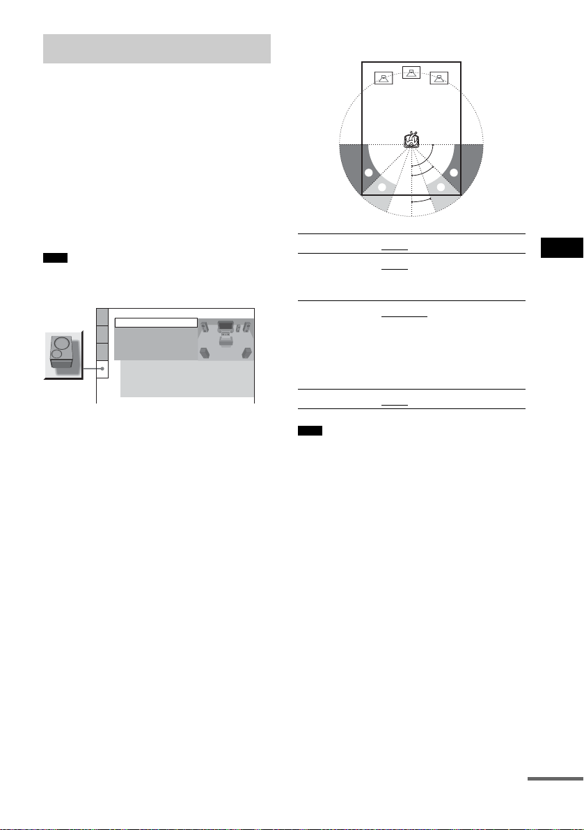
Settings for the Speakers
[SPEAKER SETUP]
To obtain the best po ssible surround sound, set
for the size of the s peakers you have connected
and their distance from your listening position.
Then use the test tone to adjust the level and the
balance of the speakers to the same level.
Select [SPEAKER SETUP] in the Setup
Display. For details, see “Using the Setup
Display” (page 70).
The default settings are underlined.
Note
• You cannot operate these setup items whe n you
connect headphones to the system.
SPEAKER SETUP
SIZE:
DISTANCE:
LEVEL(FRONT):
LEVEL(SURROUND):
TEST TONE:
FRONT:
CENTER:
SURROUND:
SUBWOOFER:
OFF
YES
YES
BEHIND
YES
Position diagram
[FRONT]
[CENTER]
[SURROUND]
[SUBWOOFER]
90
AA
45
BB
20
[YES]
[YES]: Normally select this.
[NONE]: Select this if no center
speaker is used.
[BEHIND]: Select this if surround
speakers are located in se ction B.
[SIDE]: Select th is if surround
speakers are located in se ction A.
[NONE]: Select this if no
surround speaker is used.
[YES]
Settings and Adjustments
To return to the default setting
when changing a setting
Select the item, then press CLEAR. Note that
only the [SIZE] setting does not return to the
default setting.
x [SIZE]
If you do not connec t center or surround
speakers, or move the surround speakers, set the
parameters for [CENTER] and [SURROUND]
and specify t he surroun d speaker pos ition. Si nce
the front speaker set ting is fixed, you ca nnot
change them.
Note
• When you select an item, the sound cuts off for a
moment.
• Depending on the settings of other speakers,
subwoofer may be excessive.
x [DISTANCE]
The default distance setting for the speakers in
relation to the listening po sition is s hown below.
When you set the distance using the Quick Setup
(page 28), the settings is automatically
displayed.
continued
75
US

1.0 - 7.0 m/
4 - 23 ft
0.0 - 7.0 m/
0 - 23 ft
Be sure to change the value in the Setup Display
when you move the speakers.
[FRONT]
3.0 m/10 ft
[CENTER]
3.0 m/10 ft
(appears when
you set
[CENTER] to
[YES] in the
[SIZE] setting.)
[SURROUND]
3.0 m/10 ft
(appears exce pt
when you set
[SURROUND]
to [NONE] in the
[SIZE] setting.)
* When you perform the Quick Setup (page 28), the
default settings are changed.
Note
• When you set the distance, the sound cuts off for a
moment.
• If all front and surround speakers are not placed at an
equal distance from your liste ning position, set the
distance according to the closest speake r.
• Do not place the surround speakers farther away from
your listening position than the front speakers.
• Depending on the input stream, the [DISTANCE]
setting may not be effective.
Front speaker distance from the
*
listening position can be set in 0.2
meter (1 ft) increments from 1.0 to
7.0 meters (4 to 23 ft).
Center speaker distance from th e
*
listening position can be set in 0.2
meter (1 ft) increments from 0.0 to
7.0 meters (0 to 23 ft).
Surround speaker distance from the
*
listening position can be set in 0.2
meter (1 ft) increments from 0.0 to
7.0 meters (0 to 23 ft).
x [LEVEL (FRONT)]
You can vary the level of front speake rs as
follows. Be sure to set [TEST TONE] to [ON]
for easy adjustment.
[L]
0 dB
[R]
0 dB
[CENTER]
0 dB
(appears when you
set [CENTER] to
[YES] in the [SIZE]
setting.)
[SUBWOOFER]
0 dB
Set this between –6 dB and 0 dB
in 1 dB increments.
Set this between –6 dB and 0 dB
in 1 dB increments.
Set this between –6 dB and +6 dB
in 1 dB increments.
Set this between –6 dB and +6 dB
in 1 dB increments.
x [LEVEL (SURROUND)]
You can vary the level of surround speakers as
follows. Be sure to se t [TEST TON E ] to [ON]
for easy adjustment.
(This settings appear except when you set
[SURROUND] to [NONE] in the [SIZE]
setting.)
[L]
0 dB
[R]
0 dB
Set this between –6 dB and +6 dB in
1 dB increments.
Set this between –6 dB and +6 dB in
1 dB increments.
To adjust the volume of all the
speakers at one time
Use the VOLUM E control on the system, or
press VOLUME +/– on the remote.
x [TEST TONE]
The speakers will emit a test tone to adjust
[LEVEL (FRONT)] and [LEVEL
(SURROUND)].
[OFF]
[ON]
The test tone is not emi tte d f rom the
speakers.
The test tone is emitted from each spe aker
in sequence while adjustin g lev el. When
you select one of the [SPEAKER SETUP]
items, the test tone is emitted from each
speaker in sequence.
Adjusting the speaker level by using the test tone
1 Press DISPLAY when the system is
in stop mode.
The Control Menu appears.
76
US

2 Press X/x to select [SE TUP],
then press ENTER.
The options for [SETUP] appear.
3 Press X/x to select [CUSTOM], then
press ENTER.
The Setup Disp l ay appears.
4 Press X/x repeatedly to select
[SPEAKER SETUP], then press ENTER
or c.
5 Press X/x repeatedly to select [TEST
TONE], then press ENTER or c.
6 Press X/x repeatedly to select [ON],
then press ENTER.
You will hear the tes t t one from each
speaker in sequence.
7 From your listening position, adjust the
value of [LEVEL (FRONT)] or [LEVEL
(SURROUND)] using C/X/x/c.
The test tone is emitted from only the
speaker whic h you are adjusting .
8 Press ENTER when you have finished
making adjustments.
9 Press X/x repeatedly to select [TEST
TONE], then press ENTER.
10Press X/x repeatedly to select [OFF],
then press ENTER.
Note
• When you adjust the speaker settings, the sound cuts
off for a moment.
Settings and Adjustments
77
US

Additional Information
Precautions
On your TV’s color
• If the speakers should cause the T V screen to have
color irregularity, turn off the TV then turn it on after
15 to 30 minutes . I f color irregularity should per s ist,
place the speakers farther away from th e se t.
On placement
• Place the system in a locat io n with adequate
ventilation to pr ev en t h eat build-up in the system.
• At high volume, over long periods of time, the cabinet
becomes hot to the touch. This is not a malf unction.
However, touching the cabinet should be avoided. Do
not place the unit in a confined space where
ventilation is poor a s this may caus e overheating.
• Do not block the ventilation slots by putting anything
on the system. The system is equipped with a high
power amplifier. If the ventilation slots are blocked,
the unit can overheat and malfunc ti on.
• Do not place the system on a so ft surface such as a rug
and do not block the ventilation holes.
• Do not place the system in a locat ion near heat
sources, or in a place subject to direct sunlight,
excessive dust, or mechanical shock.
On operation
• If the system is brought directly from a cold to a warm
location, or is placed in a very damp room, moisture
may condense on the lenses inside the system. Should
this occur, the system may not operate properly. In
this case, remove the d isc and leave the syste m turned
on for about half an hour until the moisture
evaporates.
• When you move the system, take out any disc. If you
don’t, the disc may be damaged.
On adjusting volume
• Do not turn up the volume while listening to a section
with very low level inputs or no audio signals. If you
do, the speakers may be damaged when a peak level
section is suddenly played.
On cleaning
• Clean the cabinet, panel, and controls with a soft cloth
slightly mo istened with a mild deterg ent soluti on. Do
not use any type of abrasive pad, scouring powder or
solvent such as alcohol or benzin e.
If you have any questions or problems concerning
your system, please consult your nearest Sony dealer.
On cleaning discs
• Do not use a commercially available CD/DVD
cleaning disc. It may cause a malfunction.
IMPORTANT NOTICE
Caution: This system is capabl e of holding a still
video image or on-screen display ima ge on your
television screen inde f initely. If you leave the stil l
video image or on-screen displa y ima ge displayed
on your TV for an extended period of time you risk
permanent damage to your television screen.
Projection televisions are especially susceptible to
this.
On moving the system
When you carry the system, use the following
procedure to protect the inner mecha n i sm.
1 Press FUNCTION repeatedly to select
“DVD.”
2 Make sure that all discs are removed from
the system.
3 Press x and "/1 simultaneously.
“MECHA LOCK” appears in the front panel
display after “STANDBY.”
4 Remove the AC power cord (mains lead)
from the wall outlet (mains).
78
US

Notes about the Discs Troubleshooting
On handling discs
• To keep the disc clean, handle the disc by its
edge. Do not touch the surface.
• Do not stick pape r or ta pe on the disc.
• Do not expose th e di sc to direct sunlight or
heat sources such as hot air ducts, or leave it in
a car parked in direct sunlight as t he
temperature may rise considerably inside the
car.
• After playing, store the disc in its case.
On cleaning
• Before play i ng, clean the disc with a cleaning
cloth.
Wipe the disc from the center out.
• Do not use solvents such as benzine, thinner,
commercially available cleaners , or anti-stat ic
spray intended for vinyl LPs.
This system can only play back a standard
circular di sc. Using nei ther stan dard nor circ ular
discs (e.g., card, heart, or star shape) may cause
a malfunction.
Do not use a disc that has a commercially
available access or y at t ached, such as a label or
ring.
If you experience any of the following
difficulties while using the system, use this
troubleshooting guide to help remedy the
problem before requesting repairs. Should any
problem persist, consult your nearest Sony
dealer.
Power
The power is not turned on.
• Check that the AC power cord (mains lead) is
connected securely.
If “PROTECT” and “UNPLUG” appears
alternately in the front panel display.
Immediately unplug the AC power co rd (mai ns
lead) and check the following items.
• Are the + and – speaker cords short-circuited?
• Are you using only the specified speakers?
• Is anything blocking the ventilation holes of the
system?
After checking the above items and fixing any
problems, connect the AC power cord (mains lead)
again and turn on the system. If the caus e of the
problem cannot be found even after checking all the
above items, consult your nearest Sony dealer.
Picture
There is no picture.
• The vi de o con ne cting c or ds a re not connec ted
securely.
• T he vide o con ne ct ing co rds a re da ma ge d.
• The system is not connected to the correct TV
input jack (page 21).
• The video input on the TV is not set so that you
can view pictures from the system.
• Yo u hav e set pr ogr e ss ive form a t but your TV
cannot accept the signal in progressive format . In
this case, return the setting to interlace format (the
default setting) (page 22).
• Even if your TV is compatible with progressive
format (525p/625p) signals, the image may be
affected when you set progressive format. In this
case, return the setting to interlace format (the
default setting) (page 22).
Picture noise appears.
• T he disc is dirty or f law ed .
• If the pic ture o utput from your system goes
through your VCR to get to your TV, the copyprotection signal applied to some DVD programs
continued
79
Additional Information
US

could affect picture quality. If you still experience
problems even when you connect your system
directly to your TV, try connecting your system to
your TV’s S video input (page 21, 25).
Even though you set the aspect ratio in [TV
TYPE] of [SCREEN SETUP], the picture does
not fill the scr e e n .
• The aspec t rati o on the disc is fixed.
Sound
There is no sound.
• The speaker cord is not connected securely.
• Press MUTING on the remote if “MUTING ON”
is display ed in the front panel display.
• The system is in pause mode or in Slow-motion
Play mode. Press H to return to normal play
mode.
• Fast forward or fast reverse is performed. Press
H to return to normal pla y mode.
• Check the speaker settings (page 75).
The left and right sounds are unbalanced or
reversed.
• Check that the speakers and components are
connected correctly and securely.
There is no sound from the subwoofer.
• Check the speaker connections and sett i n gs
(page 14, 75).
• Set the sound field to “AUTO FORMAT DIRECT
AUTO” (page 54).
Severe hum or noise is heard .
• Check that the speakers and components are
connected securely.
• Check that the connecting cords are away from a
transformer or mot or , a nd at l eas t 3 me te rs ( 10ft)
away from your TV set or a fluorescent light.
• Move your TV awa y fro m the au dio c omponents.
• The plugs a nd ja cks are dirty. Wipe them with a
cloth slightly moistened wit h al co hol.
• Clean the disc.
The sound loses stereo effect when you play a
VIDEO CD, a CD, or an MP3.
• Set [AUDIO] to [STEREO] by pressing AUDIO
(page 52).
• Make sure the system is connected properly.
The surround effect is difficult to hear when
you are playing a Dolby Digital, DTS, or MPEG
audio sound track.
• Make sure the sound field function is on
• Check the speaker connections a nd set ting s (pag e
14, 75).
(page 54).
• Depending on the DVD, the output signal may not
be the entire 5.1 channel. It may be monaural or
stereo even if the sound track is recorded in Dolby
Digital or MPEG audio format.
The sound comes from the center speaker
only.
• Depending on the disc, the sound may come from
the center speaker only.
No sound is heard from the center speake r.
• Check the spe a ke r conn ections and settings.
• Make sure the sound field function is on
• Depending on the source, the effect of the center
speaker may be less noticeabl e.
No sound or only a very low-level sound is
heard from the surround speakers.
• Check the spe a ke r conn ections and settings.
• Make sure the sound field function is on
• Depending on the source, the effect of the
surround speakers may be less notic e ab le .
(page 54).
(page 54).
Operation
Radio stations cannot be tuned in.
• Check that the antenna (aerial) is connected
securely. Adjust th e antenna ( aerial) or co nnect an
external antenna (aerial ) if necessary.
• The signal str e ngth of the stations is too weak
(when tuning in with automatic tuning). Use direct
tuning.
• No stations have been preset or the preset stations
have been cleared (when tuning by scanning
preset stations). Preset the stations (page 66).
• Press DISPLAY so that the frequency appears in
the front panel display.
The remote does not function.
• There are obs ta cl e s bet we en the remote and the
system.
• The distance between the remote and the system is
too far.
• The remote is not pointed at the remote sensor on
the system.
• The batteries in the remote are weak.
The disc does not play.
• There is no dis c i nserted.
• The disc is upside down.
Insert the disc with the playback side facing down.
• The disc is sk ewed on the disc tray.
• The system cannot play CD-ROMs, etc. (page 6).
• The region code on the DVD does not match the
system.
• Moistur e has c onde nse d inside the system and
may cause damage to the lenses. Remove the disc
80
US

and leave the system turned on for about half an
hour.
The MP3 audio track cannot be played.
• The DATA CD is not recorded in the MP3 format
that conforms to ISO 9660 Level 1/Level 2 or
Joliet.
• The MP3 audio track does not have the extension
“.MP3.”
• The data is n ot fo r ma tt ed in MP3 even though it
has the extension “.MP3.”
• The data is not MPEG1 Audio Layer 3 data.
• The system cannot play audio tracks in MP3PRO
format.
• The [MODE (MP3, JPEG)] setting has been set to
[IMAGE (JPEG)] (page 42).
• If you cannot change the [MODE ( MP3, JPEG)]
setting, re-load the disc or turn the system off, then
on.
The JPEG image file cannot be played.
• The DATA CD is not recorded in a JPEG format
that conforms to ISO 9660 Level 1/Level 2, or
Joliet.
• It has an extension other than “.JPEG” or “.JPG.”
• It is larger th an 3, 072 (width) × 2,048 (height) in
normal mode, or more than 3,300,000 pixels in
Progressive JPEG.
• It does not fit the screen (those images are
reduced).
• The [MODE (MP3, JPEG)] setting has been set to
[AUDIO (MP3)] (page 42).
• If you cannot change the [MODE ( MP3, JPEG)]
setting, re-load the disc or turn the system off, then
on.
The MP3 audio tracks and JPE G image file
starts playing simult aneously.
• [AUTO] has been selected in [MODE (MP3,
JPEG)] (page 42).
The titles of album/track/file name are not
displayed correctly.
• The system can only display numbers and letters
of the alphabets. Other characters are displayed as
[*].
A disc does not start playing from the
beginning.
• Program play, Shuffle Play, or Repeat Play has
been selected.
Press CLEAR to cancel these functions before
playing a disc.
• Resume Play has been selected.
During stop, press x on the system or the remote
and then start playback (page 32).
• T he title, DVD or PBC menu automatically
appears on the TV screen.
The system starts playing the disc
automatically.
• The DVD features an auto playback function.
Playback stops automatically.
• Som e disc s ma y c onta in an auto pause signal.
While playing such a disc, the system stops
playback at the auto pause si gna l.
You cannot perform some functions such as
Stop, Search, Slow-motion Play, or Repeat
Play.
• Depe nding on the disc, you may not be able to
perform some of the operations above. See the
operating manual that came with the disc.
Messages do not appear on the screen in the
language you want.
• In th e S et up Display, select the desired languag e
for the on-screen display in [OS D ] unde r
[LANGUAGE SETUP] (page 71).
The language for the sound track cannot be
changed.
• Multilingual tracks are not recorded on the DVD
being played.
• The DVD prohibits changing the language for the
sound track.
The subtitle language cannot be changed.
• Multilingual subtitles are not recorded on the
DVD being played.
• The DVD prohibits changing th e subtitles.
The subtitle cannot be turned off.
• The DVD prohibits turning off subtitles.
The angles cannot be changed.
• Multi-angles are not recorded on the DVD being
played (page 58).
• The DVD prohibits chang ing the angles.
A disc cannot be ejected and “LOCKED”
appears in the front panel display.
• Contact your Sony dealer or local authorized Sony
service facility.
[Data error] appears on the TV screen whe n
playing a DATA CD.
• The MP3 audio track/JPEG image file you want to
play is broken.
• The data is not MPEG1 Audio Layer 3 data.
• T he JPEG image file format does not conform to
DCF.
• T he JPEG image file has the extension “.JPG” or
“.JPEG,” but is not in JPEG format.
Additional Information
continued
81
US

The system does not work nor mally.
• Disconnect the AC power cord (mains lead) fr om
the wall outlet (mains), then reconnect after
several minutes.
Self-diagnosis Function
(When letters/numbers appear in the
display)
When the self- diag no si s func ti on is ac tiv at ed to
prevent the system from malfunctioning, a 5character servi ce number (e.g., C 13 50) with a
combination of a le tter and 4 digits appears on
the screen and the front panel display. In this
case, check the following table.
C:13:50
First 3
characters of
the service
number
C 13 The disc is dirty.
C 31 The disc is not inserted correctly.
E XX
(xx is a number)
Cause and/or corrective action
,Clean the disc with a soft cloth
(page 79).
,Restart the system, the n re-insert
the disc correctly.
To prevent a malfunction, the
system has performed the selfdiagnosis function.
,Contact your nearest Sony
dealer or local auth o rized Sony
service facility and give the 5character service number.
Example: E 61 10
82
US

Specifications
AUDIO POWER SPECIFICATIONS
POWER OUTPUT AND
TOTAL HARMONIC
DISTORTION: With 3 ohm loads, both
channels dr iv en, from
200 – 20,000 Hz; rated
55 watts per channel
minimum RMS power,
with no more th an 0.7 %
total harmonic distortion
from 250 milli watts to
rated output.
Amplifier section
DAV-DX170
Surround mode (reference) music power output
Front: 143 W + 143 W
(with SS-TS31)
Center*: 143 W
(with SS-CT31)
Surround*: 143 W + 143
W
(with SS-TS31B)
Subwoofer*: 285 W
(with SS-WS32)
DAV-DX250
Surround mode (reference) music power output
Front: 143 W + 143 W
(with SS-TS41)
Center*: 143 W
(with SS-CT31)
Surround*: 143 W + 143
W
(with SS-TS31B)
Subwoofer*: 285 W
(with SS-WS32)
* Depending on the sound field settings and the source,
there may be no sound output.
Inputs
VIDEO/SAT (AUDIO IN) Sensitivity: 250/450 mV
Impedance: 50 kilohms
Phones Accepts low-and high-
impedance headphones.
DVD system
Laser Semiconductor laser
(DVD: λ = 650 nm)
(CD: λ = 790 nm)
Emission duration:
Signal format system NTSC
Frequency response (at 2 CH STEREO mod e)
continuous
DVD (PCM): 2 Hz to 22
kHz (±1.0 dB)
CD: 2 Hz to 20 kHz (±1.0
dB)
Tuner section
System PLL quartz-locked digital
FM tuner section
Tuning range 87.5 – 108.0 MHz
Antenna (aerial) FM wire antenna (aerial)
Antenna (aerial) terminals 75 ohms, unbalanced
Intermediate frequency 10.7 MHz
AM tuner section
Tuning range 530 – 1,710 kHz (with the
Antenna (aerial) AM loop antenna (aerial)
Intermediate frequency 450 kHz
synthesizer system
(100 kHz step)
interval set at 10 kHz)
531 – 1,710 kHz (with the
interval set at 9 kHz)
Video section
Outputs Video: 1 Vp-p 75 ohms
S video:
Y: 1 Vp-p 75 ohms
C: 0.286 Vp-p 75 ohms
COMPONENT:
Y: 1 Vp-p 75 ohms
PB/CB, PR/CR: 0.7 Vp-p
75 ohms
Speakers (DAV-DX170)
Front
Speaker system Bass reflex, magnetically
Speaker unit 65 mm (2
Rated impedance 2.7 ohms
Dimensions (approx.) 90 × 132 × 107 mm
Mass (approx.) 0.6 kg (1 lb 6 oz)
shielded
cone type
(3
(w/h/d)
5
/8 inches) dia.
5
/8 × 5 1/4 × 4 1/4 inches)
Center
Speaker system Bass reflex, magnetically
Speaker unit 65 mm (2
Rated impedance 2.7 ohms
shielded
cone type
5
/8 inches) dia.
Additional Information
continued
83
US

Dimensions (approx.) 200 × 92 × 107 mm
7
/8 × 3 5/8 × 4 1/4 inches)
(7
(w/h/d)
Mass (approx.) 0.7 kg (1 lb 9 oz)
Surround
Speaker system Bass reflex
Speaker unit 65 mm (2
5
/8 inches) dia.
cone type
Rated impedance 2.7 ohms
Dimensions (approx.) 90 × 132 × 107 mm
5
/8 × 5 1/4 × 4 1/4 inches)
(3
(w/h/d)
Mass (approx.) 0.5 kg (1 lb 2 oz)
Subwoofer
Speaker system Bass reflex, magnetically
Speaker un it 160 mm (6
shielded
3
/8 inches) dia.
cone type
Rated impedance 1.3 ohms
Dimensions (approx.) 200 × 312 × 321 mm
7
(7
/8 × 12 3/8 × 12 3/4
inches)
(w/h/d)
Mass (approx.) 5.0 kg (11 lb 1 oz)
Speakers (DAV-DX250)
Front
Speaker system Bass reflex, magnetically
Speaker unit 70 mm (2
shielded
7
/8 inches) dia.
cone type
Rated impedance 2.7 ohms
Dimensions (approx.) 260 × 1,110 × 260 mm
1
(10
/4 × 43 3/4 × 10 1/4
inches)
(w/h/d)
Mass (approx.) 3.5 kg (7 lb 12 oz)
Rated impedance 2.7 ohms
Dimensions (approx.) 90 × 132 × 107 mm
5
/8 × 5 1/4 × 4 1/4 inches)
(3
(w/h/d)
Mass (approx.) 0.5 kg (1 lb 2 oz)
Subwoofer
Speaker system Bass reflex, magneti cal ly
Speaker unit 160 mm (6
shielded
3
/8 inches) dia.
cone type
Rated impedance 1.3 ohms
Dimensions (approx.) 200 × 312 × 321 mm
7
(7
/8 × 12 3/8 × 12 3/4
inches)
(w/h/d)
Mass (approx.) 5.0 kg (11 lb 1 oz)
General
Power requirements 120 V AC, 60 Hz
Power consumption On: 16 0 W
Standby: 0.3 W (at the
Power Saving Mode)
Dimensions (approx.) 430 × 88 × 415 mm
(17 × 3
1
/2 × 16 3/8 inches)
(w/h/d) incl. projecting
parts
Mass (approx.) 5.0 kg (11 lb 1 oz)
Supplied accessories See page 12.
Design and specifications are subject to change
without notice.
Center
Speaker system Bass reflex, magnetically
shielded
Speaker unit 65 mm (2
cone type
Rated impedance 2.7 ohms
Dimensions (approx.) 200 × 92 × 107 mm
7
(7
/8 × 3 5/8 × 4 1/4 inches)
(w/h/d)
Mass (approx.) 0.7 kg (1 lb 9 oz)
Surround
Speaker system Bass reflex
Speaker unit 65 mm (2
cone type
US
84
5
/8 inches) dia.
5
/8 inches) dia.

Glossary
Album
Section of a music piece or an image on a data
CD containing MP3 audio tracks or JPEG fil es.
Chapter
Subdivision of a title on a DVD. A title is
composed of sever al cha p t er s.
Dolby Digital
This movie theater sound format for is more
advanced than Dolby Surround Pro Logic. In
this format , the surround speakers ou t put stereo
sound with an expande d frequency range, and a
subwoofer channel for deep bass is
independently provided. This format is also
called “5.1 ” with the subwoofer channel
designed as the 0.1 channel (since it functions
only when a d eep bass effect is needed). All six
channels in this f ormat are record ed s eparately
for superior ch annel separation . F urthermore,
since all the signals are processed digitally, less
signal degradation occurs.
Dolby Pro Logic II
Dolby Pro Logic II creates five full-bandwid t h
output channels from 2 channel sources. This is
done using an advanced, high-purity ma tr i x
surround decoder that extracts the spatial
properties of the or ig inal recording with out
adding any new sounds or tonal colorations.
x Movie mode
The Movie mode is for use with stereo television
shows and all prog rams encoded in Dol by
Surround. The result is enhanced soundfie ld
directionality that approaches the qua l ity of
discrete 5.1-ch annel sound.
x Music mode
The Music mode is for use with an y stereo musi c
recordings, and provides a wide and deep sound
space.
Dolby Surround Pro Logic
As one method of decoding Dolby Surround,
Dolby Surround Pro Logic produces four
channels from 2 channel sound. Compared with
the former Dol by Surround system, D olby
Surround Pro Logic reproduces left-to-r ig ht
panning more naturally and localizes sounds
more precisely. To take full advantage of Dolby
Surround Pro Logic, you should have one pair of
surround speakers and a center speaker. The
surround speakers output monaural sound.
DTS
Digital audio com pression technology
developed b y Digi tal Thea ter Sys tems, Inc. T his
technology co nf orms to 5.1-channel surround.
This format c omprises of st ereo rear ch annel and
there is discrete subwoofer channel in this
format. DTS provides the same 5.1 discrete
channels of high qual ity di git al au dio. The goo d
channel separation is realized due to the all
channel data bei ng recorded discretely and
processed in di gitally.
DVD
A disc that contains up to 8 hours of moving
pictures even though it s diameter i s the same as
a CD.
The data capacity of a single-layer and singlesided DVD, at 4.7 GB (Giga Byte), is 7 times
that of a CD. Furt hermore , the dat a capaci ty of a
dual-layer and si ngle-sided DVD is 8. 5 GB, a
single-layer and double-s ided DVD 9.4 GB, and
a dual-layer and double-sided DVD 17 GB.
The picture da ta uses the MP EG 2 format, one of
a worldwide standard of digital com pression
technology. The picture data is compressed to
about 1/40 of its original size. The DVD also
uses the variable rate coding technology that
processes allocated data according to the st atus
of the picture.
The audio data is recorded in Dolby Digital as
well as in PCM, allo w i ng you to enjoy more
realistic au dio presence.
Furthermore, various advanced f unctions such
as the multi-angle, multilingual, and Parental
Control functions are provided with the DVD.
DVD-RW
A DVD-RW is a recordable and rewritable disc
that is the same size as a DVD VIDEO. The
DVD-RW has two different modes: VR mode
and Video mode. DVD-RWs created in Video
mode have the same format as a DVD VIDEO,
while discs created in VR (Video Recording)
mode allow the contents to be progra m m ed or
edited.
continued
85
Additional Information
US

DVD+RW
A DVD+RW (plus RW) is a recordable and
rewritable disc. DVD+RWs use a recordi n g
format that is comparable to the DVD VIDEO
format.
File
A JPEG image recorded on a DATA CD. (“File”
is an exclusive definition for this system.) A
single file consists of a single image.
Film based software, Video based
software
DVDs can be classified as Film based or Video
based software. Film based DVDs contain the
same images (24 frames per second) that are
shown at movie theaters. Video based DVDs,
such as television dramas or sit-coms, di s pl ays
images at 30 frames (or 60 fields) per second.
Interlace format
(Interlaced scanning)
The Interlace format is the NTSC standard
method for displa ying TV images at 30 fra m es
per second. Each frame is scanned tw i ce alternately between t he even n umbered sc anning
lines and then odd numbered scanning lines, at
60 times per second.
Multi-angle function
Various angles of a scene, or viewpoin ts of the
video camera are recorded on some DVDs.
Multilingual function
Several lang ua ges fo r the so und or subt itl es in a
picture are recorded on some DVDs.
Parental Cont ro l
A function of the DVD to limit playback of the
disc by the age of th e users according to the
limitation level in each country. The limitation
varies f rom disc to d isc; when it is activated,
playback is completely prohibited, violent
scenes are skipped or replaced with other scenes
and so on.
Playback Contro l (PB C )
Signals encoded on VIDEO CDs (Version 2.0)
to control playback.
By using men u screens record ed on VIDEO
CDs with PBC funct ions, you can enjo y playi ng
simple interactive programs, progra ms wi th
search functions, and so on.
Progressive format
(sequential scanning)
In contrast to the Interlace format, the
progressive format can reproduce 60 frames per
second by reprod ucing all scanning lines (525
lines for t h e N T SC system). Th e overall pic ture
quality increases and still images, text and
horizontal lines appear sharper. Thi s format is
compatible with the 525 progressive format.
Region Code
This system is used to protect copyrights. A
region number is allocated on each DVD system
or DVD disc according to the sales region. Ea ch
region code is shown on the system as well as on
the disc packaging. The system can play dis cs
that match its region code. The system can also
play discs with the “ ” mark. Even when the
ALL
region code is not shown on the DVD, t he region
limit may still apply.
Scene
On a VIDEO CD with PBC (playback control)
functions, the menu screens, moving pictures
and still pictures are div ided into se ctions call ed
“scenes.”
Title
The longest section of a picture or music feature
on a DVD, movie, etc., in video software, o r the
entire album in audio software.
Track
Section of a picture or a m usic piece on a
VIDEO CD, CD, or MP3. An album is
composed of sever al tr acks (MP3 only).
VIDEO CD
A compact disc that contains moving pictures.
The picture data uses the MPEG 1 format, one of
a worldwide standard of digital compression
technology. The pict ur e data is compressed to
about 1/140 of its original size. Consequently, a
12 cm VIDEO CD can contain up to 74 minutes
of moving pictures.
VIDEO CDs also con t ain compact audio data.
Sounds outside th e range of human hearin g are
compressed while sounds we can hear are not
compressed. VIDEO CDs can hold 6 times the
audio informatio n of conventional audio C D s.
There are 2 versions of V ID EO CDs.
86
US

• Version 1.1: You can play only moving
pictures and soun ds.
• Version 2. 0: You c an play high-r esolut ion st ill
pictures and enjoy PBC functions.
This system conform s t o both versions.
Additional Information
87
US

Language Code List
g
The language spe lli ngs conform to the IS O 639: 1988 (E/F) standard.
Code Language Code Language Code Language
1027 Afar
1028 Abkhazian
1032 Afrikaans
1039 Amharic
1044 Arabic
1045 Assamese
1051 Aymara
1052 Azerbaijani
1053 Bashkir
1057 Byelorussian
1059 Bulgarian
1060 Bihari
1061 Bislama
1066 Bengali; Bangla
1067 Tibetan
1070 Breton
1079 Catalan
1093 Corsican
1097 Czech
1103 Welsh
1105 Danish
1109 German
1130 Bhutani
1142 Greek
1144 English
1145 Esperanto
1149 Spanish
1150 Estonian
1151 Basque
1157 Persian
1165 Finnish
1166 Fiji
1171 Faroese
1174 French
1181 Frisian
1183 Irish
1186 Scots Gaelic
1194 Galician
1196 Guarani
1203 Gujarati
1209 Hausa
1217 Hindi
1226 Croatian
1229 Hungarian
1233 Armenian
1235 Interlingua
1239 Interlin
ue
1245 Inupiak
1248 Indonesian
1253 Icelandic
1254 Italian
1257 Hebrew
1261 Japanese
1269 Yiddish
1283 Javanese
1287 Georgian
1297 Kazakh
1298 Greenlandic
1299 Cambodian
1300 Kannada
1301 Korean
1305 Kashmiri
1307 Kurdish
1311 Kirghiz
1313 Latin
1326 Lingala
1327 Laothian
1332 Lithuanian
1334 Latvian; Lettish
1345 Malagasy
1347 Maori
1349 Macedonian
1350 Malayalam
1352 Mongolian
1353 Moldavian
1356 Marathi
1357 Malay
1358 Maltese
1363 Burmese
1365 Nauru
1369 Nepali
1376 Dutch
1379 Norwegian
1393 Occitan
1403 (Afan) Oromo
1408 Oriya
1417 Punjabi
1428 Polish
1435 Pashto; Pushto
1436 Portuguese
1463 Quechua
1481 Rhaeto-Romance
1482 Kirundi
1483 Romanian
1489 Russian
1491 Kinyarwanda
1495 Sanskrit
1498 Sindhi
1501 Sangho
1502 Serbo-Croatian
1503 Singhalese
1505 Slovak
1506 Slovenian
1507 Samoan
1508 Shona
1509 Somali
1511 Albanian
1512 Serbian
1513 Siswati
1514 Sesotho
1515 Sundanese
1516 Swedish
1517 Swahili
1521 Tamil
1525 Telugu
1527 Tajik
1528 Thai
1529 Tigrinya
1531 Turkmen
1532 Tagalog
1534 Setswana
1535 Tonga
1538 Turkish
1539 Tsonga
1540 Tatar
1543 Twi
1557 Ukrainian
1564 Urdu
1572 Uzbek
1581 Vietnamese
1587 Volap k
1613 Wolof
1632 Xhosa
1665 Yoruba
1684 Chinese
1697 Zulu
1703
Not specified
88
US

Index to Parts and Controls
For more information, refer to the pages indicated in parentheses.
Front panel
Additional Information
A "/1 (on/standby) (27, 31, 69)
B Disc tray (31)
C DISC 1-5 (31)
D A (open/close) (31, 69)
E H (play) (31)
F X (pause) (32)
G x (stop) (32, 69)
H ./> (32)
I FUNCTION (31)
J PHONES jack (31)
K VOLUME (31)
L (remote sensor) (12)
M Front panel display (90)
89
US

Front panel display
About the indications in the front panel display
A Lights up during PBC playback.
(VIDEO CD only) (37)
B Lights up when the time information of
a title or chapter appears in the front
panel disp lay . (DVD only)
C Monaural/Stereo effect (Radio only)
(67)
D Lights up when 2 channel source is
output from the surround speakers.
(55)
E Current sound effect (57)
F Current surround format (Except for
JPEG) (53)
G Current mode (DVD function only )
H Playing status (DVD function only)
90
US

Rear panel
FRONT R FRONT L SURR R SURR L CENTER WOOFER
SPEAKER
A SPEAKER jacks (14)
B VIDEO/SAT AUDIO IN jacks (23, 25)
C COMPONENT VIDEO OUT jacks (21)
AUDIO IN
VIDEO/SAT
R L
Y
PB/CBPR/C
DVD ONLY
COMPONENT VIDEO OUT
R
VIDEOS (DVD ONLY)
VIDEO
MONITOR OUT
AM
COAXIAL
FM
75
D MONITOR OUT (VIDEO / S VIDEO) ja cks
(21)
E AM terminal (20)
F FM 75Ω COAXIAL jack (20)
Additional Information
91
US

Remote
A TV [/1 (on/standby) (63)
B TV/VIDEO (63)
C TUNER MENU (66)
D SLEEP (68)
E DISC SKIP (31)
F PROGRESSIVE (22)
G REPEAT/FM MODE (35, 67)
H TUNER/BAND (67)
I Number buttons (36, 59, 63)
The number 5 button has a tactile dot.*
J CLEAR, - (28, 33, 64)
K TOP MENU (36)
L C/X/x/c/ENTER (27, 33, 54, 59, 65, 69,
70)
M O RETURN (37)
N REPLAY, STEP (32)
O . PRESET –, TV CH – (28, 32, 63, 67)
P m/ SLOW, TUNING – (45, 66)
Q H (play) (31)
The H button has a tactile dot.*
R TV (63)
S THEATRE SYNC (64)
T "/1 (on/standby) (27, 31, 67)
U AMP MENU (27, 65, 69)
V DSGX (57)
W FUNCTION (22, 31, 56, 65)
X SOUND FIELD (54)
Y DISPLAY (67)
Z PICTURE NAVI (41)
wj AUDIO (52)
wk SUBTITLE (58)
wl ANGLE (58)
e; ALBUM –/+ (32, 64)
ea MENU (36)
es MUTING (32)
ed VOLUME, TV VOL +/– (31, 63, 67)
The VOLUME, TV VOL + button has a
tactile dot.*
ef DISPLAY (9, 28, 33, 59, 70)
eg > PRESET +, TV CH + (28, 32, 63, 67)
eh ADVANCE, STEP (32)
ej M/ SLOW, TUNING + (45, 66)
ek x (stop) (32, 59, 67)
el X (pause) (32)
* Use the tactile dot as a reference when operating the
system.
92
US

DVD Setup Display List
You can set the following items with the DVD Setup Display.
The order of the displayed items may be different from the actual displa y.
LANGUAGE SETUP
OSD
MENU
AUDIO
AUDIO
SUBTITLE
SUBTITLE
(Select the language you
want to use from the
displayed language list.)
(Select the language you
want to use from the
displayed language list.)
(Select the language you
(Select the language you
want to use from the
want to use from the
displayed language list.)
displayed language list.)
(Select the language you
want to use from the
displayed language list.)
CUSTOM SETUP
PAUSE
MODE
TRACK
SELECTION
MULTI-DISC
RESUME
AUDIO DRC
AUTO
FRAME
OFF
AUTO
ON
OFF
OFF
STANDARD
MAX
SCREEN SETUP
TV TYPE
SCREEN SAVER
BACKGROUND
BLACK LEVEL
BLACK LEVEL
(COMPONENT
OUT)
4:3 OUTPUT
SPEAKER SETUP
SIZE
DISTANCE
LEVEL
(FRONT)
LEVEL
(SURROUND)
TEST TONE
FRONT
CENTER
SURROUND
SUBWOOFER
FRONT 1.0 m – 7.0 m/
CENTER
SURROUND
L
R
CENTER
SUBWOOFER
L
R
OFF
ON
4:3 LETTER
BOX
4:3 PAN SCAN
16:9
ON
OFF
JACKET
PICTURE
GRAPHICS
BLUE
BLACK
ON
OFF
OFF
ON
FULL
NORMAL
YES
YES
NONE
BEHIND
SIDE
NONE
YES
4 ft – 23 ft
0.0 m – 7.0 m/
0 ft – 23 ft
0.0 m – 7.0 m/
0 ft – 23 ft
–6 dB – 0 dB
–6 dB – 0 dB
–6 dB – +6 dB
–6 dB – +6 dB
–6 dB – +6 dB
–6 dB – +6 dB
Additional Information
93
US

AMP Menu List
You can set the following items with AMP MENU on the remote.
AMP menu
DIMMER
DEMO DEMO ON
ATTENUATE
DIMMER ON
DIMMER OFF
DEMO OFF
ATT ON
ATT OFF
94
US

Index
Numerics
16:9 72
4:3 LETTER BOX 72
4:3 OUT PUT 73
4:3 PAN SCAN 72
5.1 Channel Surround 53
A
A/V SYNC 44
Accessories 12
ALBUM 46
Album 85
AMP menu 27
AMP menu list 94
ANGLE 58
Antenna (aerial) Hookup 20
ATTENUATE 66
AUDIO 71
AUDIO DRC 74
B
BACKGROUND 72
Batteries 12
BLACK LEVEL 73
BLACK LEVEL
(COMPONENT OUT) 73
C
CHAPTER 46
Chapter 85
COMPONENT VIDEO OUT
22
Connecting the AC power cord
(mains lead) 27
Continuous play 31
Control Menu 9
Controlling the TV 63
CUSTOM 70
CUSTOM PARENTAL
CONTROL 59
CUSTOM SETUP 74
D
DATA CD 40
DEMO 27
Demonstr ation 27
DIMMER 69
DISC SKIP 32
DISPLAY 49
Display
Setup Display 70
DISTANCE 75
DOLBY DIGITAL 52
Dolby Digital 85
Dolby Pro Logic II 85
Dolby Surround Pro Logic 85
DSGX 57
DTS 52, 85
DVD 85
DVD+R W 86
DVD’s menu 36
DVD-RW 37, 85
E
EFFECT 44
F
Fast forward 45
Fast reverse 45
FILE 46
File 86
Film based software 86
Front Panel 89
Front panel display 49, 90
H
Handling discs 79
Hookup Overview 13
I
INDEX 46
Installing the speakers on the
wall 18
Instant Advance 32
Instant Replay 32
Interlace format 86
INTERVAL 43
J
JPEG 38, 40
L
Language Code List 88
LANGUAGE SETUP 71
LEVEL (FRONT) 76
LEVEL (SURROUND) 76
Listening to other compon ents
65
Listening to TV sound 56
Locating
a specific point by watching
the TV screen 45
M
MENU 71
MODE (MP3, JPEG) 42
MP3 38, 40
Multi Session CD 7
Multi-angle function 58, 86
MULTI-DISC RESUME 74
Multilingual function 86
Muting 32
N
Naming preset stati ons 67
O
On-screen display
Control Menu display 9
Setup Display 70
ORIGINAL 37
OSD 71
Other Component Hook up 25
P
PARENTAL CONTROL 60, 86
PAUSE MODE 74
PBC Playback 7, 37, 86
PICTURE NAVI 41, 48
PLAY LIST 37
Preset Station 66
Program Play 33
PROGRESSIVE AUTO 22
Progressive format 22, 86
PROGRESSIVE VIDEO 23
Q
Quick Setup 28
R
Radio 67
Rear Panel 91
Region Code 7, 86
Remote 12, 63, 92
Repeat Play 35
RESET 71
Resume Play 32
S
S VIDEO 21
Scan 45
SCENE 46
Scene 86
continued
95
US

SCREEN SAVER 72
SCREEN SETUP 72
Searching 45
SETUP 70
Setup Display 70, 93
Shuffle Play 34
SIZE 75
SLEEP 68
Slide show 42
Slow-motion play 45
Sound Field 54
SPEAKER SETUP 75
Speaker setup 30
Speaker System Hookup 14
SUBTITLE 58, 71
T
TEST TONE 76
THEATRE SYNC 64
TIME/TEXT 47
TITLE 46
Title 86
TRACK 46
Track 86
TRACK SELECTION 74
Troubleshooting 79
TUNER MENU 66
TV Hookup 21
TV TYPE 72
U
Usable discs 6
V
VIDEO CD 86
Sony Corporation
Printed in China
 Loading...