

Page 1
8
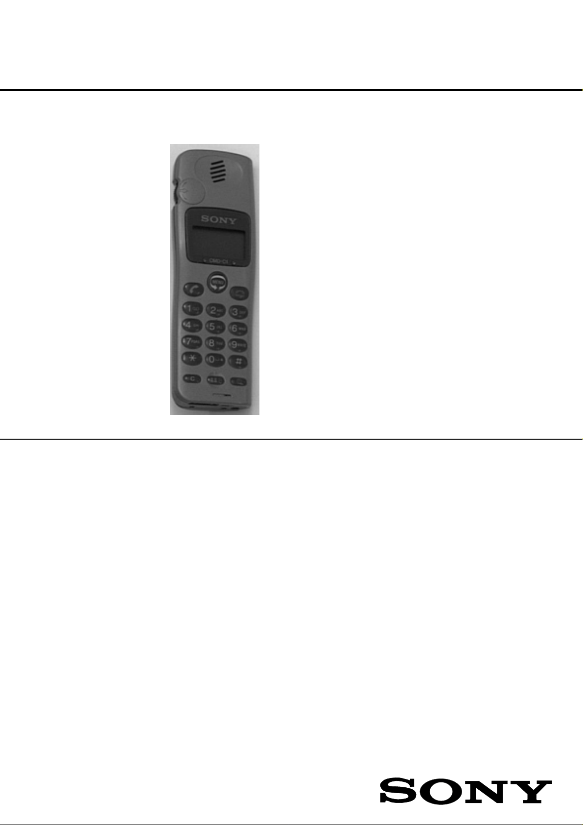
SERVICE MANUAL
CMD-C1/C
CMD-C1 : AEP Model
UK Model
AUS Model
CMD-C8 : China Model
SPECIFICATIONS
Signalling format GSM
Frequency range Transmit: 890 ~ 915 MHz
Receive: 935 ~ 960 MHz
GSM power class Class 4 (2 W)
SIM chip Pluggable mini SIM card
Display High resolution full graphics display
Resolution: 97 x 33 pixels
1 header line for icons
3 lines x 16 large characters
Channel spacing 200 kHz
Number of channels 124
Frequency stability Transmit frequency drift (synchronized)
< ± 0.1 p.p.m.
RF output power 2 W
Power requirements 3.5 V ~ 4.0 V (nominal)
Battery life Standby : up to 115h
Talk time : up to 5.5h
PORTABLE DIGITAL CELLULAR TELEPHONE
WITH ACCESSORIES
Page 2

Operating temperature –10°C to +55°C
Accessories operating temperature 0°C to +45°C
Battery pack charging temperature 0°C to +40°C
Dimensions 98 mm x 60 mm x 26 mm
Weight 107 g
Volume 114 cm
3
Supplied accessories Power adaptor QN-C11AC (AEP), QN-C12AC (UK),
QN-C13AC (AUS), QN-C81AC (China)
Optional accessories Handsfree kit QN-C1HFK
Cigar lighter charger QN-C1CC
Design and specifications are subject to change without prior notice.
This appliance conforms with EEC Directive 87/308/EEC regarding interference suppression.
2
Page 3
SECTION 1
OPERATING INSTRUCTIONS
The Basic Features of Your CMD-C1
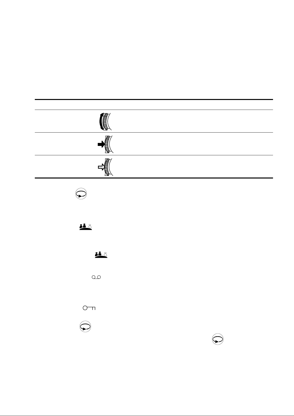
The Jog Dial
TheJogDialprovidesone-handedoperationnavigatedby yourleft hand, freeing your right handforotheractivity
like taking notes, etc. Give the Jog Dial a quick turn in either direction in standby mode to spin through the main
menu options. With one simple press of the Jog Dial in standby mode (the Network Operator name appears on
the display), the Phonebook is at your fingertips. Press and hold the Jog Dial (for more than one second) to call
a Phonebook selection or number on the display.
Operation Function
Rotate Scrolls through menu options.
Press
(click)
Press and hold Dials the phone number selected.
MENU
Selects an option (highlighted) in the display.
Accepts an entry made by alphanumeric keys.
Exits from one menu to the previous one.
The Menu Key
In standby mode, press the Menu key and then use the Jog Dial to spin through the Main Menu with options to
change your phone settings and access different features. See also Menu Operation.
The Manner key
This is the key to good mobile phone manners. Press the Manner Key once to quickly turn the ringer to silent
mode to avoid disturbance. Just press twice and the ringer is restricted to a descrete single beep. To turn the
ringer on again, simply press the Manner Key again. During a call you can also press the Manner key once to
mutethemicrophone;press againtoturnonthemicrophone.Foryourreference, the optionsyouactivated
using the Manner Key are indicated by an icon in the display.
The Voice Mail Key
To speed dial your Voice Mail, press and hold the 1 Key to automatically dial your “personal answering service”
to listen to messages, etc. See also Phonebook, Voice Mail.
1
The keypad Lock
Your CMD-C1 can be locked to avoid involutary dialling or menu scrolling especially when carrying your mobile
MENU
phone. Simply press followed by the # key to lock your CMD-C1 keypad and even the Jog Dial restricting
MENU
any activity EXCEPT emergency calls (112). Simply repeat the key combination ( then # key) in order to
unlock your CMD-C1 again.
3
Page 4
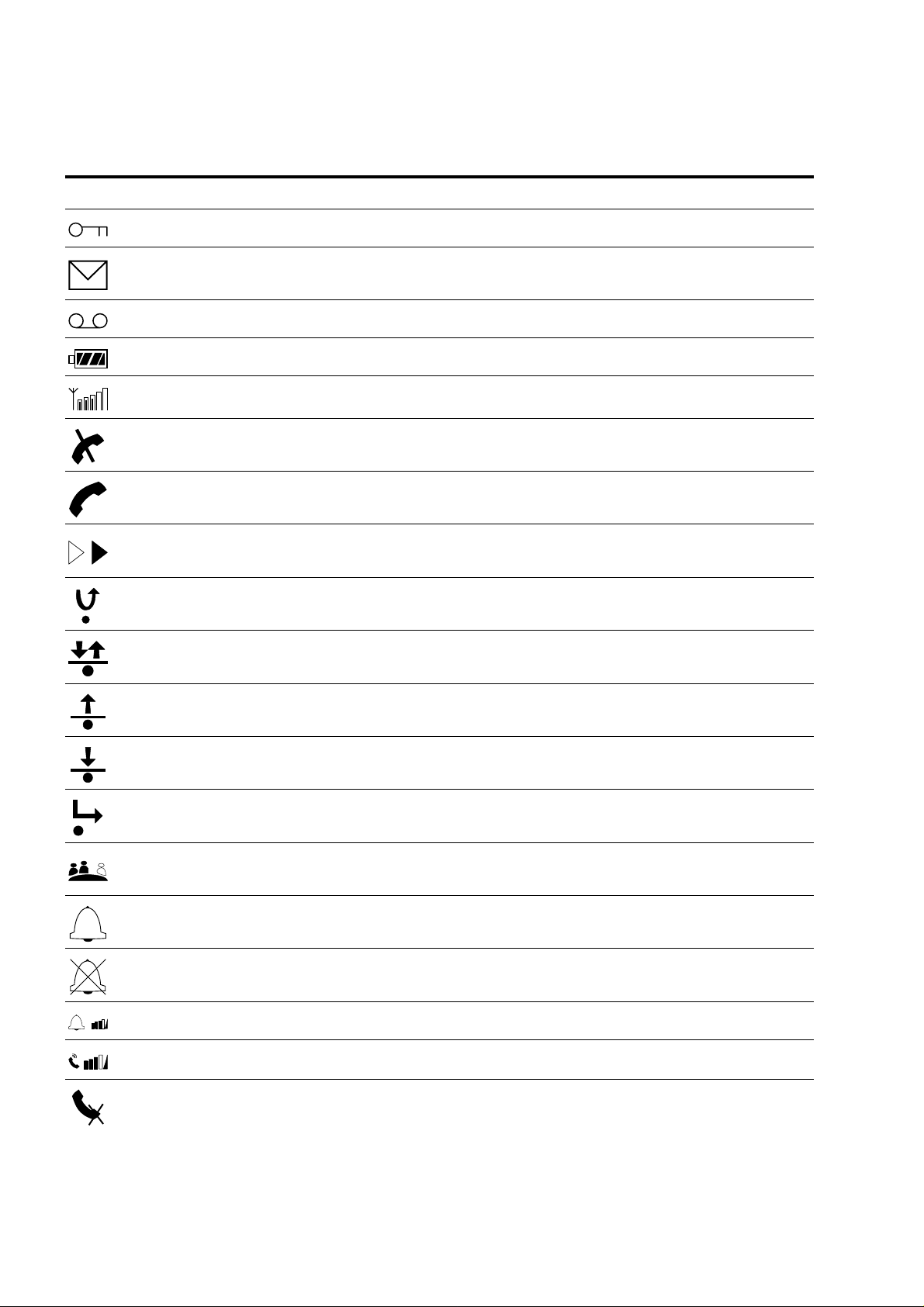
Icon Glossary
The Sony CMD-C1 lets you see at a glance if you have missed calls, have messages waiting, and the status of
options you have selected (like if you have diverted your phone or turned the ringer off). Sony has developed
the following icons to provide you with a quick overview of your mobile activity :
Icon Explanation
Keypad locked
SMS Message waiting (flashing = SMS memory storage full)
Voice Mail Notification
Battery strength (flashing = battery level low)
Network Signal strength
Network not available (no calls possible)
Incoming call
Option activated
Missed calles (Priority 1)
Limit Calls In/Out activated (Priority 2)
Limit Calls Out activated (Priority 2)
Limit Calls In activated (Priority 2)
Divert options activated (Priority 3)
Ringer switched to Silent Mode (Priority 5)
!
Ringer switched to Single Beep
Ringer switched to volume 0
Ringer Volume choices
Speaker Volume
Microphone Mute
4
Page 5

Menu Overview
Rotate the Jog Dial or press the Menu key from standby mode to access the main menu :
DIVERT
(page 24)
If Not
Reachable
If No Reply
If Busy
All Calls
Clear All
MESSAGING
(page 26)
Read
Create
ServiceCentre
Settings
LocalArea Info
REDIAL
LIST
(page 32)
Last Calls
Received Calls
Missed Calls
CONTROL
(page 33)
Security
Network Services
Call Cost
PREFERENCES
(page 42)
Caller ID
Language
Ringer V olume
Ringer Tone
Any Key Answer
Key Click Sound
DTMF KeyTones
Illumination
Auto Redial
Auto Answer
1 Minute Beep
Factory Settings
5
Page 6

SECTION 2
DISASSEMBLY
Important notes :
1.The IMEI sticker mounted on the main board (visible from the battery compartment) should under no
condition be removed. The IMEI number is the electronic identification of the hardware, it is also stored
electronically and at no time is a discrepancy between number on the sticker and number within the set
logic allowed.
2.The antenna unit can only be lifted off as a unit to allow access to parts underneath. The antenna itself
needs to be handled with care. Damage, deformation or incorrect mounting of the patch antenna can lead
to incorrect performance and even interference of the set.
1. Remove the battery cover and the battery. Note
that the SIM card is also located in this area.
3. The lower claws can be released by gently
pushing the upper case to left/right versus the
lower case.
2.Remove 4 screws inthebatterycompartment. The
upper and lower case are held by a number of
claws, positions are indicated.
4. Insert the hook release jig (p/n 9-948-370-20) in
the gap between upper and lower cosmetic, as
indicated in the picture.
6
Page 7

5. Push the hook release jig gently to thelower side,
while holding the CMD-C1. In this way the hook
release jig is used as a lever. More clamps
between upper and lower case will now release
and the parts can be taken out.
6. The front cosmetic andback cosmetic can now be
separated, and the main board can be taken out.
7. The display unit can be lifted out. The LCD is
connected with a flex cable and the LCD support
8. Remove 6 screws located on the display side to
release the patch antenna.
is clamped onto themain board (2 clamps left and
right side).
9. Unsolder the antenna on the right side. The patch antenna assy can now be lifted off. fIt should be
considered as one non-serviceable and sensitive item.
7
Page 8

10. Parts on the main board specified in the parts list can now be reached.
For reassembly, apply the disassembly procedure in reverse order.
8
Page 9

SECTION 3
PROGRAMMING INSTRUCTIONS
1. Setup
The software programming setup requires a PC (386 type or higher), the Level Shifter (LS-1), Connection Cable
to the PC and the Level Shifter extension.
• Connect the RS 232 cable from the Level Shifter to the com-port of the PC (com 1 or com 2).
• Connect the Level Shifter extension between CMD-C1 and the Level Shifter.
• Connect the power supply to the Level Shifter.
No specific software installation is needed; only copy all the files to the PC.
PREPARATION FOR SOFTWARE UPDATE
PIN
JIG
1.LEVELSHIFTER LS - 1
2.INTERFACEADAPTER
WITHTHE PIN - JIG
2. Important notes
INTERFACE
ADAPTER
GSM conn.
LEVELSHIFTER
LS - 1
rs-232
• Before connecting the CMD−C1 to the Level Shifter, take out the battery of the CMD−C1; the CMD−C1
must be powered from the Level Shifter with the GSM-switch. All other switches are always in the
ON-position.
• The initial settings of the flash.exe program may not correspond with the normal correct settings. It is
highly advisable to check the settings first (see below).
9
Page 10

3. Software setup
∗
Loading new software into the flash.
• Start the program flash.exe by double-clicking on its icon in the explorer.
• Select “File”/“Settings...” and check if the settings for the “Com Port”, the “Baud Rate” and the “Erase Mode”
are correct. Normally the “Load Options” do not have to be changed. The default values are :
Com Port: COM 1
Baud Rate: 115200
Load Options: Both
Erase Mode: Program Area, Smart Erase (!disable melody
area erase for normal software update)
After changing the settings, the new values are stored in the file “flash.ini” in the windows directory.
• Select “File”/“Open...” to select an S record file for downloading. The C1.SRE file contains the software for
C1. Any other .SRE file is either only needed for the program itself, or can be a melody file (see below).
• Press the “LOAD” button of the program.
• Power-on the mobile.
• Now the program runs automatically.
NOTE
– Please note that the CMD-C1 makes it possible to load only the different ringer melodies without
changing the rest of the software programs.
– For this procedure it is necessary to change the settings on the flash-loader for “EraseMode” to
MELODY AREA instead of PROGRAM AREA, then load the new file c1melody.sre.
– Remember to change the flash-loader settings back to PROGRAM AREA.
– ! Whenever performing software update or melody software update, please remember that the erase
settings (in the settings menu) should be correctly set.
10
Page 11

SECTION 4
EXPLODED VIEW
11
Page 12

SECTION 5
SPARE PARTS AND ACCESSORIES LIST
Ref. No. Part Number Description Comment
1 X 3376 296 1
X 3377 190 1
X 3377 192 1
X 3377 191 1
X 3377 193 1 Upper Case Metallic Red
2 3 031 795 01
3 3031 807 01
4 3 031 839 01
5 A 3647 481 A
6 3 031 803 02
7 3 031 804 01
8 1 529 191 11
9 1 542 381 11
10 1 759 436 21
11 3 031 801 01
12 1 418 057 21
13 1 785 460 31
14 1 785 698 21
15 1 695 320 21
16 1 785 461 21
17 1 528 950 11 Battery Pack
18 3 031 806 01
19 3 032 991 01
Instruction Manual
3 865 514 81
3 865 514 11
3 865 514 41
3 865 514 61
3 865 514 21
3 865 514 31
3 865 514 51
3 865 514 71
3 865 575 11
3 865 575 41
3 865 575 61
3 865 575 51
3 865 575 91 French
3 865 575 21
AC Power Supply
1 418 229 11
1 418 229 12
1 418 229 21
1 418 382 11
Jigs
9 948 320 40
9 948 370 20
9 948 320 60
9 948 360 30
Upper Case Orig. Grey
Upper Case Classic Silver
Upper Case Pearl White
Upper Case Metallic Blue
Lower Case
Lid, Battery
Cap, Antenna
LCD, Assy
Cushion LCD
Rubber Key
Speaker
Microphone
Ringer
Cushion, Ringer
Jog-Dial
DC Jack
I/O Connector
Battery Connector
SIM Connector
Screw 2,0x10
Screw 1,4x4,5
German CMD-C1 // F1 (CE1)
German / Italian CMD-C1 // SF1 (CE1)
Swedish/ Norwegian
Spanish / Portuguese
English
French / Dutch CMD-C1 // SF1 (CE1)
Danish / Finnish
Greek / Turkish
Czech / Polish
Chinese (Traditional)
Chinese (Simplified)
Arabic
Hungarian / Romanian
QN-C11AC Euro
QN-C12AC UK
QN-C13AC Australia
QN-C81AC Chinese
Level Shifter LS 1
Hook Release Jig
Level Shifter extension LS 1/C 1
Service Connection cradle
C1//F1
C1/SF1
C1/WF1
C1/LF1
C1/RF1
9-948-436-10
Sony Customer Relations & Service Europe
European Technical Support
English
Printed in Belgium
1999.02
Published by ETS
 Loading...