

Sony CDXGT-41-UW, CDXGT-410-U, CDXGT-460-U, CDXGT-460-US Service manual
CDX-GT41UW/GT410U/
GT460U/GT460US
SERVICE MANUAL
Ver. 1.2 2007.03
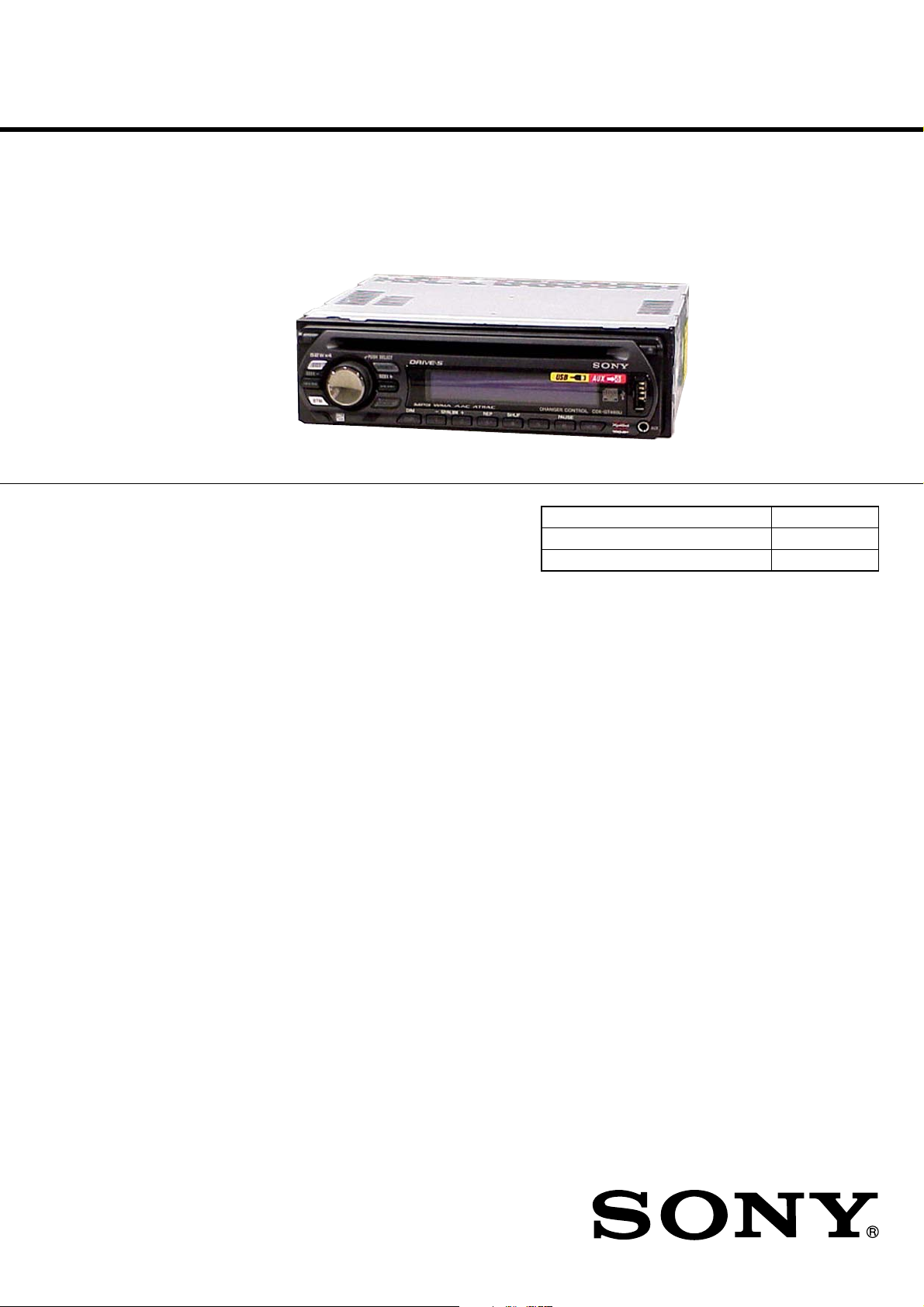
(Photo: CDX-GT460U)
• The tuner and CD sections have no adjustments.
AUDIO POWER SPECIFICATIONS (US MODEL)
POWER OUTPUT AND TOTAL HARMONIC DISTORTION
23.2 watts per channel minimum continuous average power into
4 ohms, 4 channels driven from 20 Hz to 20 kHz with no more
than 5% total harmonic distortion.
US Model
Canadian Model
CDX-GT41UW/GT410U
E Model
CDX-GT460U/GT460US
Chinese Model
CDX-GT460U
Model Name Using Similar Mechanism NEW
CD Drive Mechanism Type MG-101U-188//Q
Optical Pick-up Name DAX-25A
CD player section
Signal-to-noise ratio 120 dB
Frequency response 10 – 20,000 Hz
Wow and flutter Below measurable limit
Tuner section
FM
Tuning range GT41UW/GT410U:
87.5 – 107.9 MHz
GT460U/GT460US:
87.5 – 108.0 MHz (at 50 kHz step)
87.5 – 107.9 MHz (at 200 kHz step)
FM tuning interval GT460U/GT460US:
50 kHz/200 kHz switchable
Antenna terminal External antenna connector
Intermediate frequency 10.7 MHz/450 kHz
Usable sensitivity 9 dBf
Selectivity 75 dB at 400 kHz
Signal-to-noise ratio 67 dB (stereo), 69 dB (mono)
Harmonic distortion at 1 kHz
0.5% (stereo), 0.3% (mono)
Separation 35 dB at 1 kHz
Frequency response 30 – 15,000 Hz
SPECIFICATIONS
AM
Tuning range GT41UW/GT410U:
530 – 1,710 kHz
GT460U/GT460US:
531 – 1,602 kHz (at 9 kHz step)
530 – 1,710 kHz (at 10 kHz step)
AM tuning interval GT460U/GT460US:
9 kHz/10 kHz switchable
Antenna terminal External antenna connector
Intermediate frequency 10.7 MHz/450 kHz
Sensitivity 30 µV
USB player section
Interface USB (Full-speed)
Maximum current 500 mA
Power amplifier section
Outputs Speaker outputs (sure seal connectors)
Speaker impedance 4 – 8 ohms
Maximum power output
52 W × 4 (at 4 ohms)
– Continued on next page –
9-887-470-03
2007C04-1
© 2007.03
FM/AM COMPACT DISC PLAYER
Sony Corporation
eVehicle Division
Published by Sony Techno Create Corporation
CDX-GT41UW/GT410U/GT460U/GT460US
Ver. 1.1
General
Outputs Audio outputs terminal (sub/rear switchable)
Inputs BUS control input terminal
Tone controls Low: ±10 dB at 60 Hz (XPLOD)
Power requirements 12 V DC car battery (negative ground)
Dimensions Approx. 178 × 50 × 179 mm
Mounting dimensions Approx. 182 × 53 × 162 mm
Mass Approx. 1.2 kg (2 lb. 11 oz.)
Supplied accessories Card remote commander: RM-X151
Design and specifications are subject to change without
notice.
US and foreign patents licensed from Dolby
Laboratories.
Power antenna relay control terminal
Power amplifier control terminal
BUS audio input terminal
Antenna input terminal
AUX input jack (stereo mini jack)
Mid: ±10 dB at 1 kHz (XPLOD)
High: ±10 dB at 10 kHz (XPLOD)
(7
1/8 × 2 × 7 1/8 in.) (w/h/d)
(7 1/4 × 2 1/8 × 6 1/2 in.) (w/h/d)
Parts for installation and connections (1 set)
USB cap
SERVICE NOTES
Notes on Chip Component Replacement
•Never reuse a disconnected chip component.
•Notice that the minus side of a tantalum capacitor may be damaged
by heat.
TEST DISCS
Please use the following test discs for the check on the CD section.
YDES-18 (Part No. 3-702-101-01)
PATD-012 (Part No. 4-225-203-01)
CAUTION
Use of controls or adjustments or performance of procedures
other than those specified herein may result in hazardous
radiation exposure.
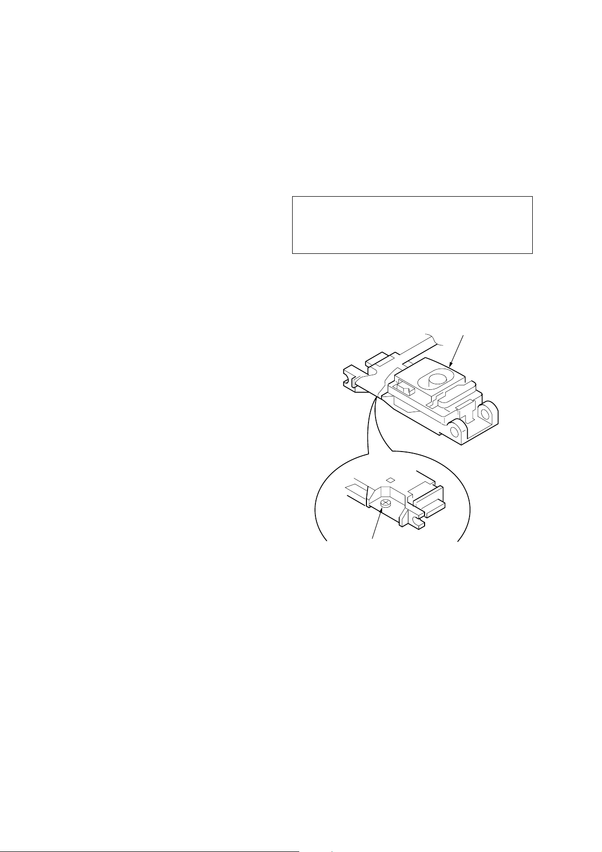
If the optical pick-up block is defective, please replace the whole
optical pick-up block.
Never turn the semi-fix ed resistor located at the side of optical pickup block.
optical pick-up
NOTES ON HANDLING THE OPTICAL PICK-UP BLOCK
OR BASE UNIT
The laser diode in the optical pick-up block may suffer electrostatic
breakdown because of the potential difference generated by the
charged electrostatic load, etc. on clothing and the human body.
During repair, pay attention to electrostatic breakdown and also use
the procedure in the printed matter which is included in the repair
parts.
The flexible board is easily damaged and should be handled with
care.
NOTES ON LASER DIODE EMISSION CHECK
The laser beam on this model is concentrated so as to be focused on
the disc reflective surface by the objective lens in the optical pickup block. Therefore, when checking the laser diode emission,
observe from more than 30 cm away from the objective lens.
semi-fixed resistor
SAFETY-RELATED COMPONENT WARNING!!
COMPONENTS IDENTIFIED BY MARK 0 OR DOTTED LINE
WITH MARK 0 ON THE SCHEMATIC DIAGRAMS AND IN
THE PARTS LIST ARE CRITICAL TO SAFE OPERATION.
REPLACE THESE COMPONENTS WITH SONY P ARTS WHOSE
PART NUMBERS APPEAR AS SHOWN IN THIS MANUAL OR
IN SUPPLEMENTS PUBLISHED BY SONY.
2
ATTENTION AU COMPOSANT AYANT RAPPORT
À LA SÉCURITÉ!!
LES COMPOSANTS IDENTIFIÉS P AR UNE MARQUE 0 SUR LES
DIAGRAMMES SCHÉMATIQUES ET LA LISTE DES PIÈCES
SONT CRITIQUES POUR LA SÉCURITÉ DE FONCTIONNEMENT.
NE REMPLACER CES COMPOSANTS QUE PAR DES PIÈCES
SONY DONT LES NUMÉROS SONT DONNÉS DANS CE MANUEL
OU DANS LES SUPPLÉMENTS PUBLIÉS PAR SONY.
CDX-GT41UW/GT410U/GT460U/GT460US
D
This compact disc player is classified as a CLASS 1 LASER
product. The CLASS 1 LASER PRODUCT label is located on the
exterior.
E model
This label is located on the bottom of the chassis.
Chinese model
• CD playback
You can play CD-DA (also containing CD TEXT*), CD-R/CDRW (MP3/WMA/AAC files also containing Multi Session) and
ATRAC CD (ATRAC3 and ATRAC3plus format).
Type of discs Label on the disc
UNLEADED SOLDER
•
Boards requiring use of unleaded solder are printed with the leadfree mark (LF) indicating the solder contains no lead.
(Caution:Some printed circuit boards may not come printed with
the lead free mark due to their particular size.)
: LEAD FREE MARK
Unleaded solder has the following characteristics.
• Unleaded solder melts at a temperature about 40°C higher than
ordinary solder.
Ordinary soldering irons can be used but the iron tip has to be
applied to the solder joint for a slightly longer time.
Soldering irons using a temperature regulator should be set to
about 350°C.
Caution:The printed pattern (copper foil) may peel away if the
heated tip is applied for too long, so be careful!
• Strong viscosity
Unleaded solder is more viscous (sticky, less prone to flow)
than ordinary solder so use caution not to let solder bridges
occur such as on IC pins, etc.
• Usable with ordinary solder
It is best to use only unleaded solder but unleaded solder may
also be added to ordinary solder.
CD-DA
MP3
WMA
AAC
ATRAC CD
*A CD TEXT disc is a CD-DA that includes information such as
disc, artist and track name.
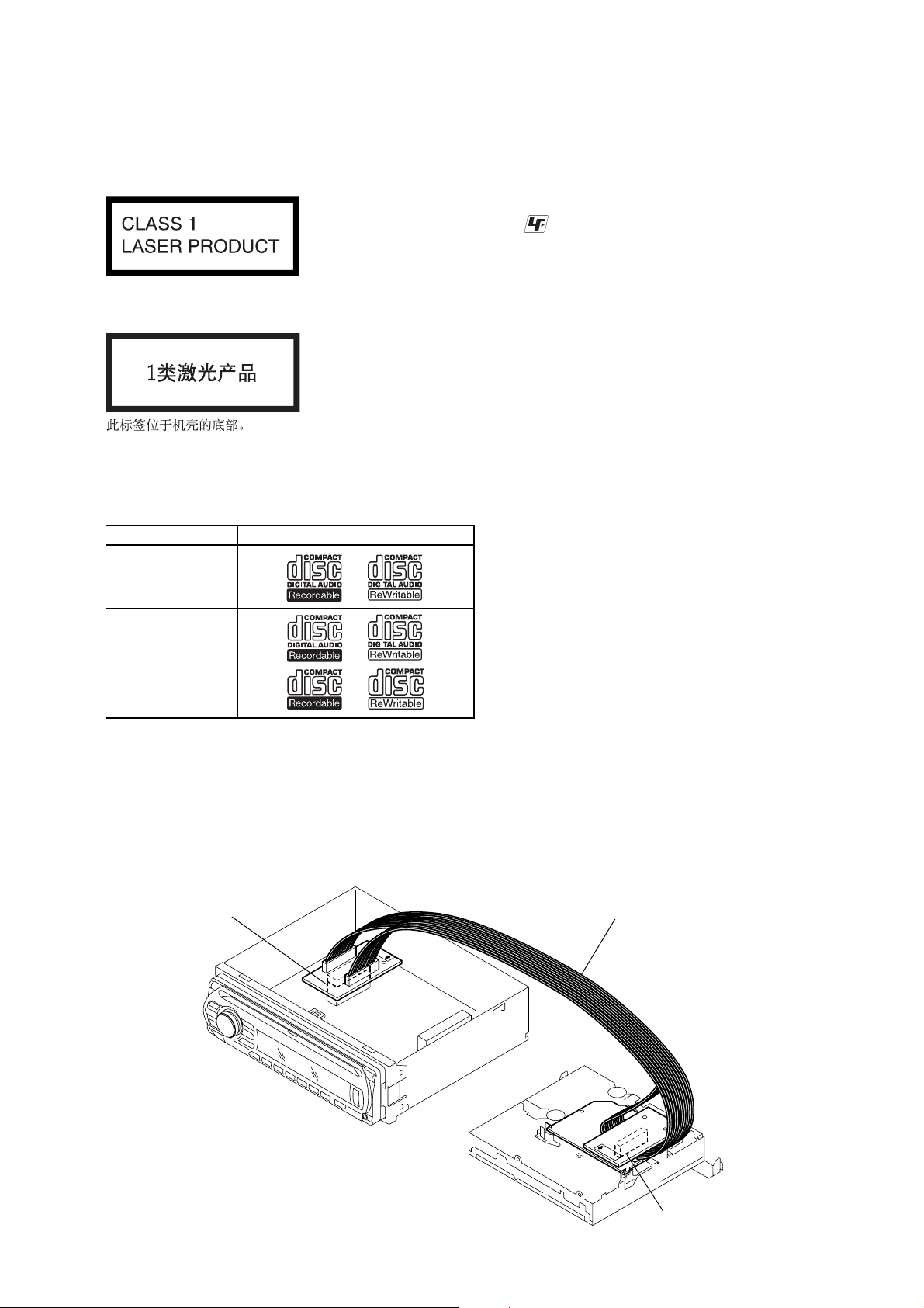
EXTENSION CABLE AND SERVICE POSITION
When repairing or servicing this set, connect the jig (extension cable)
as shown below.
• Connect the MAIN board (CN350) and the SER V O board (CN2)
with the extension cable (Part No. J-2502-076-1).
MAIN BOARD
CN350
J-2502-076-1
SERVO BOAR
CN2
3
CDX-GT41UW/GT410U/GT460U/GT460US
d
Ver. 1.2
NOTE FOR REPLACEMENT OF THE SERVO BOARD
When repairing, the complete SER VO board (A-1206-357-A) should
be replaced since any parts in the SER V O board cannot be repaired.
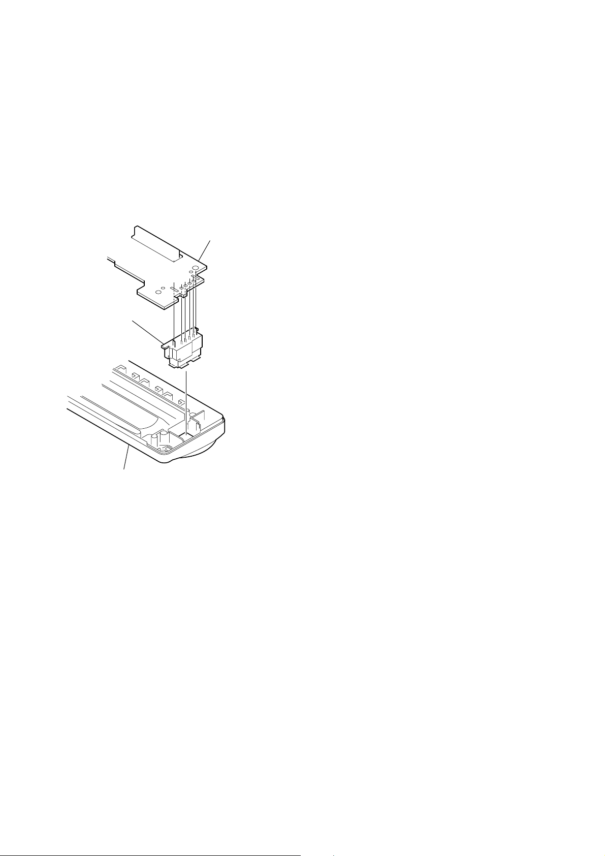
NOTE FOR REPLACEMENT OF THE USB CONNECTOR
(CN902)
To replace the USB connector requires alignment.
1. Insert the USB connector into the front panel.
2. Place the KEY board on the front panel and align the terminals
of the USB connector with the holes in the KEY board.
3. Solder the four terminals of the connector.
KEY boar
USB (socket) connector
TABLE OF CONTENTS
1. GENERAL
Location of Controls........................................................ 5
Connections ..................................................................... 6
2. DISASSEMBLY
2-1. Sub Panel (FL) Assy........................................................ 11
2-2. CD Mechanism Block ..................................................... 11
2-3. Main Board...................................................................... 12
2-4. Servo Board ..................................................................... 12
2-5. Chassis (T) Sub Assy....................................................... 13
2-6. Roller Arm Assy .............................................................. 13
2-7. Chassis (OP) Assy ........................................................... 14
3. DIAGNOSIS FUNCTION ........................................ 15
4. DIAGRAMS
4-1. Block Diagram –Main Section– ...................................... 19
4-2. Block Diagram –Display Section– .................................. 20
4-3. Printed Wiring Board –Main Section– ............................ 22
4-4. Schematic Diagram –Main Section (1/3)– ...................... 23
4-5. Schematic Diagram –Main Section (2/3)– ...................... 24
4-6. Schematic Diagram –Main Section (3/3)– ...................... 25
4-7. Printed Wiring Board –Key Section– .............................. 26
4-8. Schematic Diagram –Key Section–................................. 27
front panel
NOTE FOR THE 24-PIN CONNECTOR (CN901)
Do not use alcohol to clean the 24-pin connector (CN901) connecting
the front panel with the main body.
Do not touch the connector directly with your bare hand. Poor contact
may be caused.
5. EXPLODED VIEWS
5-1. Main Section.................................................................... 32
5-2. Front Panel Section ......................................................... 33
5-3. CD Mechanism Section (MG-101U-188//Q) .................. 34
6. ELECTRICAL PARTS LIST.................................. 35
4
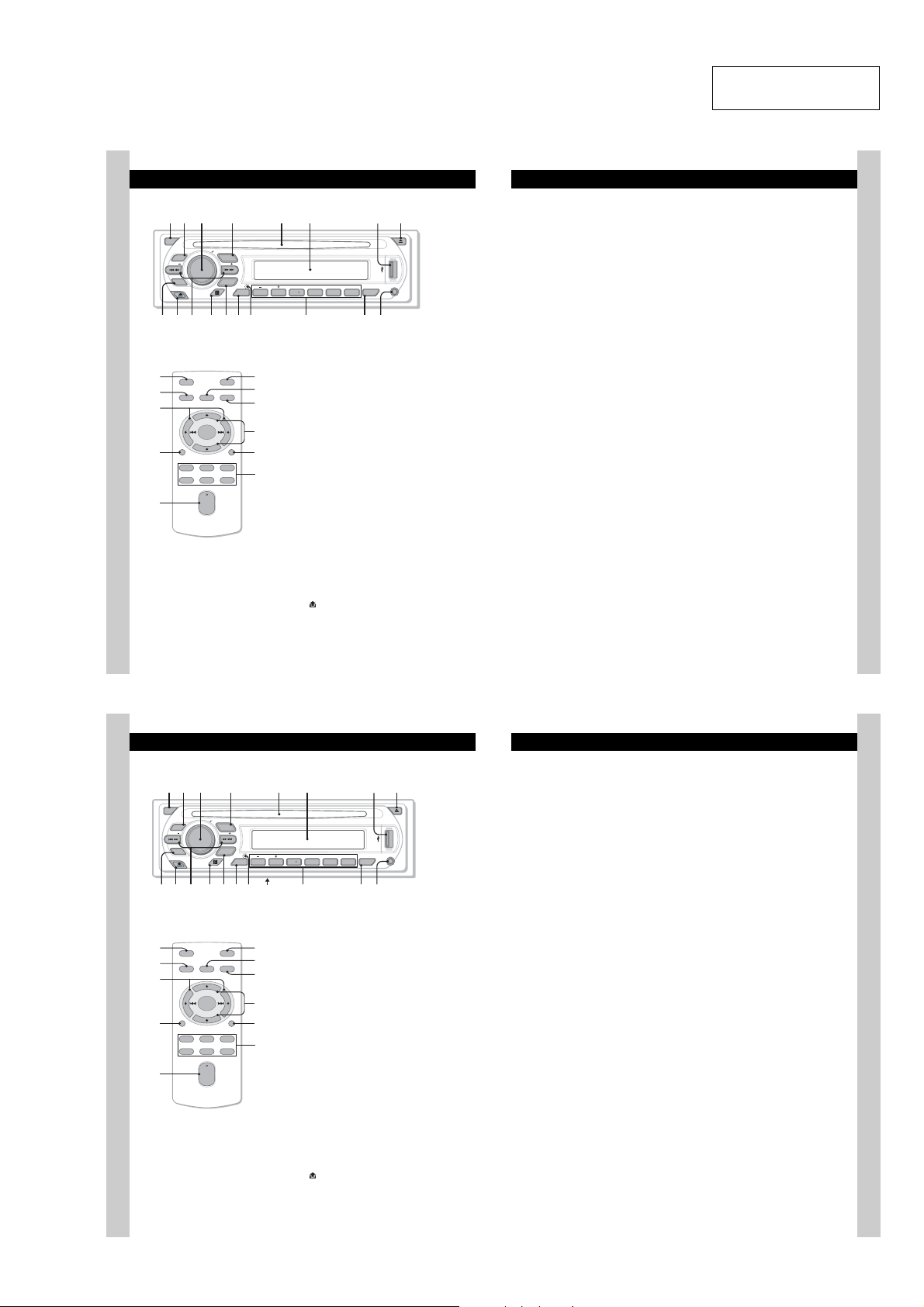
• LOCATION OF CONTROLS
1 2
4 5 863
7
1 2 4 5 863
qaq
q;9 qsqfq
7
q
q
q
q
• CDX-GT41UW/GT410U
Location of controls and basic operations
Main unit
OFF
Card remote commander
RM-X151
1
4
ql
qf
w;
PUSH SELECT
EQ3
SEEK
CAT
BTM
qa qdq;9 qs qfqg
OFF
SEL
SOURCE
+
–
DSPL
132
465
+
VOL
–
SOURCE
SEEK
MODE
DIM REP SHUF
GP/ALBM
123456
DSPL
wa
ATT
ws
MODE
qd
wd
SCRL
qj
wf
Refer to the pages listed for details. The
corresponding buttons on the card remote
commander control the same functions as those
on the unit.
A OFF button
B EQ3 (equalizer) button 10
C Volume control dial/select button 10
D SOURCE button
E Disc slot
F Display window
G USB terminal 9
H Z (eject) button
I BTM/CAT*
J (front panel release) button 5
PAUSE
AUX
SCRL
CDX-GT410U
CDX-GT41UW
qjqh
qk
To po we r off; stop the source.
To select an equalizer type (XPLOD,
VOCAL, EDGE, CRUISE, SPACE,
GRAVITY, CUSTOM or OFF).
To ad ju st vo lume (rotate); select setup items
(press and rotate).
To po we r on; change the sour ce (Radio/CD/
1
MD*
/USB/AUX/SAT*2).
Insert the disc (label side up), playback
starts.
To co nnect to the USB device.
To ej e c t the disc.
2
button 8
To st art t he BTM function (press and hold).
CDX-GT41UW/GT410U/GT460U/GT460US
SECTION 1
GENERAL
K SEEK –/+ buttons
1
/USB*3:
CD/MD*
To sk ip tracks (press); skip tracks
continuously (press, then press again within
about 1 second and hold); reverse/fastforward a track (press and hold).
Radio:
To tune in stations automatically (press); find
a station manually (press and ho ld).
L Receptor for th e card remote
commander
M MODE button 8, 10, 12
To select the radio band (FM/AM); select the
SAT tuner band (mode)*
select the play mode*
N DSPL (display)/DIM (dimmer) button
8, 9
To ch ange display it em s (press); change the
display brightness (press and hol d) .
O RESET button (located behind the front
panel) 4
P Number buttons
CD/MD*
(1)/(2): GP*
To s kip albums (press); skip albums
continuously (press and hold) *
(3): REP 8, 10
(4): SHUF 8, 10
(6): PAUS E*
To p ause playback. To cancel, press
again.
Radio:
To re ce ive stored stations (press); store
stations (press and hold).
Q SCRL (scroll) button 8, 9
To sc ro ll th e display item.
R AUX input jack 11
To co nnect a portable audio device.
1
/USB*3:
5
.
6
/ALBM*7 –/+
9
2
; select the unit*4;
8
.
This section is extracted
from instruction manual.
The following buttons on the card remote
commander have also different buttons/functions
from the unit. Remove the insulation film before
use (page 4).
ql < (.)/, (>) buttons
To control CD/radio/MD/USB, the same as
(SEEK) –/+ on the unit.
w; VOL (volume) +/– button
To adjust volume.
wa AT T (attenuate) button
To att e nuate the sound. To cancel, press
again.
ws SEL (select) button
The same as the select button on the unit.
wd M (+)/m (–) buttons
To control CD, the same as (1)/(2) (GP/
ALBM –/+) on the unit.
wf Number buttons
To r e c e ive stored st ations (press); store
stations (press and hold).
*1
When an MD changer is connected.
*2
When the SAT tuner is connected.
*3
When a USB device is connected.
*4
When a CD/MD changer is connected.
*5
When an ATRAC Audio Device is connected.
*6
When an ATRAC CD is played.
*7
When an MP3/WMA/AAC is played.
*8
If the changer/USB device is connected, the
operation is different, see page 12.
*9
When playing bac k on this unit.
Notes
•
When ejecting/inserting a disc, keep any USB
devices disconnected to avoid damage to the disc.
•
If the unit is turned off and the display disappears, it
cannot be operated with the card remote
commander unless
pressed, or a disc is inserted to activate the unit first.
Tip
For details on how to replace the battery, see
“Replacing the lithium battery of the card remote
commander” on page 15.
About USB cap
When not using the USB terminal (
supplied USB cap to prevent dust or dirt entering.
Keep the USB cap out of the reach of children to
prevent accidental swallowing.
(SOURCE)
on the unit is
G
), use the
6
• CDX-GT460U/GT460US
Location of controls and basic operations
Main unit
OFF
EQ3
SEEK
CAT
BTM
Card remote commander
RM-X151
1
OFF
4
w;
qf
wa
6
SOURCE
DSPL
132
465
SEL
+
–
+
VOL
–
PUSH SELECT
SOURCE
SEEK
MODE
DIM REP SHUF
GP/ALBM
123456
DSPL
d
g
ws
ATT
wd
MODE
qd
wf
SCRL
qk
wg
PAUSE
SCRL
h
j
Refer to the pages listed for details. The
corresponding buttons on the card remote
commander control the same functions as those
on the unit.
A OFF button
To po we r off; stop the source.
B EQ3 (equalizer) button 10
To select an equalizer type (XPLOD,
VOCAL, EDGE, CRUISE, SPACE,
GRAVITY, CUSTOM or OFF).
C Volume control dial/select button 10
To ad ju st vo lume (rotate); select setup items
(press and rotate).
D SOURCE button
To po we r on; change the sour ce (Radio/CD/
MD*
E Disc slot
Insert the disc (label side up), playback
starts.
F Display window
G USB terminal
To co nnect to the USB device. 9
H Z (eject) button
To ej e c t the disc.
I BTM button 8
To st art t he BTM function (press and ho ld).
J (front panel release) button 5
1
/USB/AUX).
k
CDX-GT460US
CDX-GT460U
l
7
K SEEK –/+ buttons
1
/USB*2:
CD/MD*
To sk ip tracks (press); skip tracks
continuously (press, then press again within
about 1 second and hold); reverse/fastforward a track (press and hold).
Radio:
To tune in stations automatically (press); find
a station manually (press and ho ld).
L Receptor for th e card remote
AUX
commander
M MODE button 8, 12
To select the radio band (FM/AM); select the
3
unit*
; select the play mode*4.
N DSPL (display)/DIM (dimmer) button
8
To ch ange display item s (press); change the
display brightness (press and hol d) .
O RESET button (located behind the front
panel) 4
P Frequency select switch (located on the
bottom of the unit)
See “Frequency select switch” i n t he
supplied installation/connections manual.
Q Number buttons
1
CD/MD*
/USB*2:
5
(1)/(2): GP*
(3): REP 8
(4): SHUF 8
(6): PAUS E*
Radio:
To re ce ive stored stations (press); store
stations (press and hold).
R SCRL (scroll) button 8
To sc ro ll th e display item.
S AUX input jack 12
To co nnect a portable audio device.
/ALBM*6 –/+
To s kip albums (press); skip albums
continuously (press and hold) *
8
To p ause playback. To cancel, press
again.
The following buttons on the card remote
commander have also different buttons/functions
from the unit. Remove the insulation film before
use (page 4).
w; < (.)/, (>) buttons
To control CD/radio/MD/USB, the same as
(SEEK) –/+ on the unit.
wa VOL (volume) +/– button
To adjust volume.
ws AT T (attenuate) button
To att e nuate the sound. To cancel, press
again.
wd SEL (select) button
The same as the select button on the unit.
wf M (+)/m (–) buttons
To control CD, the same as (1)/(2) (GP/
ALBM –/+) on the unit.
wg Number buttons
To r e c e ive stored st ations (press); store
stations (press and hold).
*1
When an MD changer is connected.
*2
When a USB device is connected.
*3
When a CD/MD changer is connected.
*4
When an ATRAC Audio Device is connected.
*5
When an ATRAC CD is played.
*6
When an MP3/WMA/AAC is played.
*7
If the changer/USB device is connected, the
operation is different, see page 12.
*8
7
.
When playing bac k on this unit.
Notes
•
When ejecting/inserting a disc, keep any USB
devices disconnected to avoid damage to the disc.
•
If the unit is turned off and the display disappears, it
cannot be operated with the card remote
commander unless
pressed, or a disc is inserted to activate the unit first.
Tip
For details on how to replace the battery, see
“Replacing the lithium battery of the card remote
commander” on page 15.
About USB cap
When not using the USB terminal (
supplied USB cap to prevent dust or dirt entering.
Keep the USB cap out of the reach of children to
prevent accidental swallowing.
(SOURCE)
on the unit is
G
), use the
7
5
CDX-GT41UW/GT410U/GT460U/GT460US
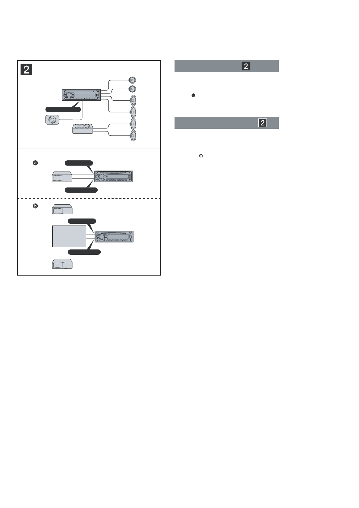
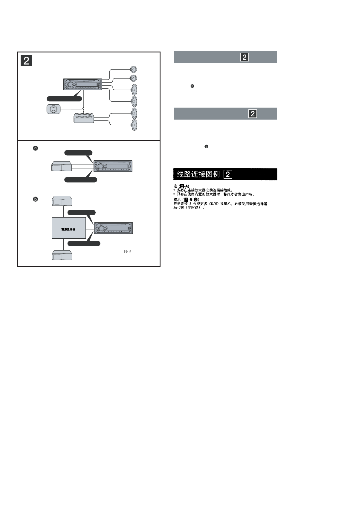
• CONNECTIONS
• CDX-GT41UW/GT410U
A
AUDIO OUT REAR
*
Connection example
Notes
(2-A)
•
Be sure to connect the ground (earth) lead before connecting
the amplifi er.
•
The alarm will only sound if the built-in amplifi er is used.
(2-B- )
Tip
For connecting two or more CD/MD changers, the source
selector XA-C40 (not supplied) is necessary.
Exemple de raccordement
B
*
AUDIO OUT SUB/REAR
BUS AUDIO IN
BUS CONTROL IN
Source selector*
Sélecteur de source*
XA-C40
BUS AUDIO IN
BUS CONTROL IN
not supplied
*
non fourni
Remarques
•
•
Conseil
Dans le cas du raccordement de deux changeurs de CD/MD ou
plus, le sélecteur de source XA-C40 (non fourni) est requis.
(2-A)
Raccordez d’abord le câble de mise à la masse avant de
raccorder l’amplifi cateur.
L’alarme est émise uniquement lorsque l’amplifi cateur intégré
est utilisé.
(2
-B-
)
6
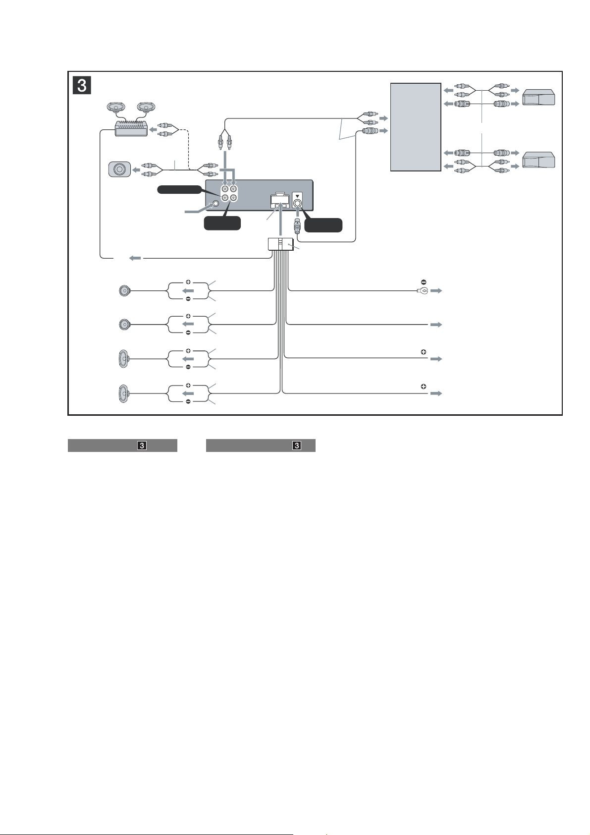
CDX-GT41UW/GT410U/GT460U/GT460US
L
R
BUS AUDIO IN
AUDIO OUT
REAR
*
2
BUS
CONTROL IN
2
4
5
1
3
AUDIO OUT
REAR/SUB
BUS
IN
AMP REM
Max. supply current 0.3 A
Courant max. fourni 0,3 A
Fuse (10 A)
Fusible (10 A)
Blue/white striped
Rayé bleu/blanc
ANT REM
Red
Rouge
Yellow
Jaune
Black
Noir
Blue
Bleu
White
Blanc
Green
Vert
Purple
Violet
White/black striped
Rayé blanc/noir
Gray/black striped
Rayé gris/noir
Green/black striped
Rayé vert/noir
Gray
Gris
Left
Gauche
Right
Droit
Left
Gauche
Right
Droit
*
1
RCA pin cord (not supplied)
*
2
AUDIO OUT can be switched SUB or
REAR. For details, see the supplied
Operating Instructions.
*
1
Cordon à broche RCA (non fourni)
*
2
AUDIO OUT peut être commuté sur SUB
ou REAR. Pour obtenir plus de détails,
reportez-vous au mode d’emploi fourni.
Purple/black striped
Rayé volet/noir
*
1
Source selector
(not supplied)
Sélecteur de source
(non fourni)
XA-C40
Supplied with the CD/MD changer
Fourni avec le changeur de CD/MD
Max. supply current 0.1 A
Courant max. fourni 0,1 A
from car antenna (aerial)
à partir de l’antenne
du véhicule
Supplied with XA-C40
Fourni avec le XA-C40
2
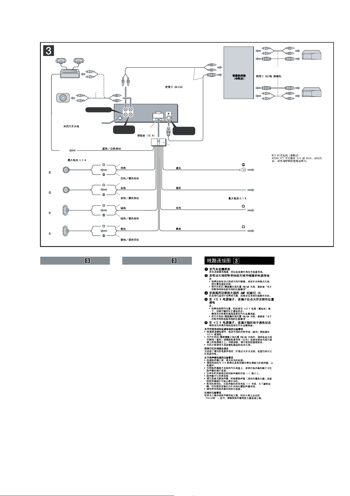
Connection diagram
1 To a metal surface of the car
2 To the power antenna (aerial) control lead or
3 To AMP REMOTE IN of an optional power
4 To the +12 V power terminal which is
5 To the +12 V power terminal which is
Notes on the control and power supply leads
•
The power antenna (aerial) control lead (blue) supplies +12 V
DC when you turn on the tuner.
•
When your car has built-in FM/AM antenna (aerial) in the rear/
side glass, connect the power antenna (aerial) control lead
(blue) or the accessory power supply lead (red) to the power
terminal of the existing antenna (aerial) booster. For details,
consult your dealer.
•
A power antenna (aerial) without a relay box cannot be used
with this unit.
Memory hold connection
When the yellow power supply lead is connected, power will
always be supplied to the memory circuit even when the ignition
switch is turned off.
Notes on speaker connection
•
Before connecting the speakers, turn the unit off.
•
Use speakers with an impedance of 4 to 8 ohms, and with
adequate power handling capacities to avoid its damage.
•
Do not connect the speaker terminals to the car chassis, or
connect the terminals of the right speakers with those of the
left speaker.
•
Do not connect the ground (earth) lead of this unit to the
negative (–) terminal of the speaker.
•
Do not attempt to connect the speakers in parallel.
•
Connect only passive speakers. Connecting active speakers
(with built-in amplifi ers) to the speaker terminals may damage
the unit.
•
To avoid a malfunction, do not use the built-in speaker leads
installed in your car if the unit shares a common negative (–)
lead for the right and left speakers.
•
Do not connect the unit’s speaker leads to each other.
Note on connection
If speaker and amplifi er are not connected correctly, “FAILURE”
appears in the display. In this case, make sure the speaker and
amplifi er are connected correctly.
First connect the black ground (earth) lead, then connect the
yellow and red power supply leads.
power supply lead of antenna (aerial) booster
Notes
•
It is not necessary to connect this lead if there is no power
antenna (aerial) or antenna (aerial) booster, or with a
manually-operated telescopic antenna (aerial).
•
When your car has a built-in FM/AM antenna (aerial) in
the rear/side glass, see “Notes on the control and power
supply leads.”
amplifi er
This connection is only for amplifi ers. Connecting any other
system may damage the unit.
energized in the accessory position of the
ignition switch
Notes
•
If there is no accessory position, connect to the +12 V
power (battery) terminal which is energized at all times.
Be sure to connect the black ground (earth) lead to a
metal surface of the car fi rst.
•
When your car has a built-in FM/AM antenna (aerial) in
the rear/side glass, see “Notes on the control and power
supply leads.”
energized at all times
Be sure to connect the black ground (earth) lead to a metal
surface of the car fi rst.
Schéma de raccordement
1 À un point métallique de la voiture
Branchez d’abord le câble de mise à la masse noir et,
ensuite, les câbles d’alimentation jaune et rouge.
2 Au câble de commande d’antenne électrique
ou au câble d’alimentation de l’amplifi cateur
d’antenne
Remarques
•
Il n’est pas nécessaire de raccorder ce câble s’il n’y a pas
d’antenne électrique ni d’amplifi cateur d’antenne, ou avec
une antenne télescopique manuelle.
•
Si votre voiture est équipée d’une antenne FM/AM
intégrée dans la vitre arrière/latérale, voir « Remarques
sur les câbles de commande et d’alimentation ».
3 Au niveau de AMP REMOTE IN de
l’amplifi cateur de puissance en option
Ce raccordement s’applique uniquement aux amplifi cateurs.
Le branchement de tout autre système risque
d’endommager l’appareil.
4 À la borne +12 V qui est alimentée quand la
clé de contact est sur la position accessoires
Remarques
•
S’il n’y a pas de position accessoires, raccordez la borne
d’alimentation (batterie) +12 V qui est alimentée en
permanence.
Raccordez d’abord le câble de mise à la masse noir à un
point métallique du véhicule.
•
Si votre voiture est équipée d’une antenne FM/AM
intégrée dans la vitre arrière/latérale, voir « Remarques
sur les câbles de commande et d’alimentation ».
5 À la borne +12 V qui est alimentée en
permanence
Raccordez d’abord le câble de mise à la masse noir à un
point métallique du véhicule.
Remarques sur les câbles de commande et d’alimentation
•
Le câble de commande d’antenne électrique (bleu) fournit une
alimentation de + 12 V CC lorsque vous mettez la radio sous
tension.
•
Lorsque votre voiture est équipée d’une antenne FM/AM
intégrée dans la vitre arrière/latérale, raccordez le câble de
commande d’antenne (bleu) ou le câble d’alimentation des
accessoires (rouge) à la borne d’alimentation de l’amplifi cateur
d’antenne existant. Pour plus de détails, consultez votre
détaillant.
•
Une antenne électrique sans boîtier de relais ne peut pas être
utilisée avec cet appareil.
Raccordement pour la conservation de la mémoire
Lorsque le câble d’alimentation jaune est raccordé, le circuit
de la mémoire est alimenté en permanence même si la clé de
contact est sur la position d’arrêt.
Remarques sur le raccordement des haut-parleurs
•
Avant de raccorder les haut-parleurs, mettez l’appareil hors
tension.
•
Utilisez des haut-parleurs ayant une impédance de 4 à 8 ohms
avec une capacité électrique adéquate pour éviter de les
endommager.
•
Ne raccordez pas les bornes du système de haut-parleurs au
châssis de la voiture et ne raccordez pas les bornes du hautparleur droit à celles du haut-parleur gauche.
•
Ne raccordez pas le câble de mise à la masse de cet appareil
à la borne négative (–) du haut-parleur.
•
N’essayez pas de raccorder les haut-parleurs en parallèle.
•
Raccordez uniquement des haut-parleurs passifs. Le
raccordement de haut-parleurs actifs (avec amplifi cateurs
intégrés) aux bornes des haut-parleurs peut endommager
l’appareil.
•
Pour éviter tout problème de fonctionnement, n’utilisez pas les
câbles des haut-parleurs intégrés installés dans votre voiture si
l’appareil partage un câble négatif commun (–) pour les hautparleurs droit et gauche.
•
Ne raccordez pas entre eux les cordons des haut-parleurs de
l’appareil.
Remarque sur le raccordement
Si les haut-parleurs ne sont pas raccordés correctement, le
message « FAILURE » s’affi che. Dans ce cas, assurez-vous que
les haut-parleurs sont bien raccordés.
7
CDX-GT41UW/GT410U/GT460U/GT460US
• CDX-GT460U/GT460US
A
B
AUDIO OUT REAR
*
AUDIO OUT SUB/REAR
*
BUS AUDIO IN
BUS CONTROL IN
Connection example
Notes
(2-A)
•
Be sure to connect the ground (earth) lead before connecting
the amplifi er.
•
The alarm will only sound if the built-in amplifi er is used.
Tip
(2-B-
For connecting two or more CD/MD changers, the source
selector XA-C40 (not supplied) is necessary.
)
Ejemplo de conexiones
Notas
(2-A)
•
Asegúrese de conectar primero el cable de conexión a masa
antes de realizar la conexión del amplifi cador.
•
La alarma sonará únicamente si se utiliza el amplifi cador
incorporado.
Sugerencia
Si desea conectar dos o más cambiadores de CD/MD,
necesitará el selector de fuente XA-C40 (no suministrado).
(2-B-
)
BUS AUDIO IN
Source selector*
Selector de fuente*
*
XA-C40
BUS CONTROL IN
not supplied
*
no suministrado
8
CDX-GT41UW/GT410U/GT460U/GT460US
L
R
BUS AUDIO IN
AUDIO OUT
REAR
*
2
BUS
CONTROL IN
2
4
5
1
3
AUDIO OUT
REAR/SUB
BUS
IN
from car antenna (aerial)
desde la antena del automóvil
*
1
RCA pin cord (not supplied)
*
2
AUDIO OUT can be switched SUB or
REAR. For details, see the supplied
Operating Instructions.
*
1
Cable con terminales RCA
(no suministrado)
*
2
AUDIO OUT (Salida de audio) puede
cambiarse a SUB (Secundaria) o REAR
(Posterior). Para obtener información,
consulte el manual de instrucciones
suministrado.
*
1
*
2
AMP REM
Max. supply current 0.3 A
Corriente máx. de alimentación de 0,3 A
Fuse (10 A)
Fusible (10 A)
Blue/white striped
Con rayas azules y blancas
Red
Rojo
Yellow
Amarillo
White
Blanco
Green
Verde
Purple
Morado
White/black striped
Con rayas blancas y negras
Grey/black striped
Con rayas grises y negras
Green/black striped
Con rayas verdes y negras
Grey
Gris
Left
Izquierdo
Right
Derecho
Left
Izquierdo
Right
Derecho
ANT REM
Black
Negro
Blue
Azul
Max. supply current 0.1 A
Corriente máx. de alimentación de 0,1 A
Purple/black striped
Con rayas moradas y negras
Source selector
(not supplied)
Selector de fuente
(no suministrado)
XA-C40
Supplied with the CD/MD changer
Suministrado con el cambiador de CD/MD
*
1
Supplied with XA-C40
Suministrado con el XA-C40
2
Connection diagram
1 To a metal surface of the car
First connect the black ground (earth) lead, then connect the
yellow and red power supply leads.
2 To the power antenna (aerial) control lead or
power supply lead of antenna (aerial) booster
Notes
•
It is not necessary to connect this lead if there is no power
antenna (aerial) or antenna (aerial) booster, or with a
manually-operated telescopic antenna (aerial).
•
When your car has a built-in FM/AM antenna (aerial) in
the rear/side glass, see “Notes on the control and power
supply leads.”
3 To AMP REMOTE IN of an optional power
amplifi er
This connection is only for amplifi ers. Connecting any other
system may damage the unit.
4 To the +12 V power terminal which is
energized in the accessory position of the
ignition switch
Notes
•
If there is no accessory position, connect to the +12 V
power (battery) terminal which is energized at all times.
Be sure to connect the black ground (earth) lead to a
metal surface of the car fi rst.
•
When your car has a built-in FM/AM antenna (aerial) in
the rear/side glass, see “Notes on the control and power
supply leads.”
5 To the +12 V power terminal which is
energized at all times
Be sure to connect the black ground (earth) lead to a metal
surface of the car fi rst.
Notes on the control and power supply leads
•
The power antenna (aerial) control lead (blue) supplies +12 V
DC when you turn on the tuner.
•
When your car has built-in FM/AM antenna (aerial) in the rear/
side glass, connect the power antenna (aerial) control lead
(blue) or the accessory power supply lead (red) to the power
terminal of the existing antenna (aerial) booster. For details,
consult your dealer.
•
A power antenna (aerial) without a relay box cannot be used
with this unit.
Memory hold connection
When the yellow power supply lead is connected, power will
always be supplied to the memory circuit even when the ignition
switch is turned off.
Notes on speaker connection
•
Before connecting the speakers, turn the unit off.
•
Use speakers with an impedance of 4 to 8 ohms, and with
adequate power handling capacities to avoid its damage.
•
Do not connect the speaker terminals to the car chassis, or
connect the terminals of the right speakers with those of the
left speaker.
•
Do not connect the ground (earth) lead of this unit to the
negative (–) terminal of the speaker.
•
Do not attempt to connect the speakers in parallel.
•
Connect only passive speakers. Connecting active speakers
(with built-in amplifi ers) to the speaker terminals may damage
the unit.
•
To avoid a malfunction, do not use the built-in speaker leads
installed in your car if the unit shares a common negative (–)
lead for the right and left speakers.
•
Do not connect the unit’s speaker leads to each other.
Note on connection
If speaker and amplifi er are not connected correctly, “FAILURE”
appears in the display. In this case, make sure the speaker and
amplifi er are connected correctly.
Diagrama de conexión
1 A una superfi cie metálica del automóvil
Conecte primero el cable de conexión a masa negro, y
después los cables amarillo y rojo de fuente de alimentación.
2 Al cable de control de la antena motorizada
o al cable de fuente de alimentación del
amplifi cador de señal de la antena
Notas
•
Si no se dispone de antena motorizada ni de amplifi cador
de antena, o se utiliza una antena telescópica accionada
manualmente, no será necesario conectar este cable.
•
Si el automóvil incorpora una antena de FM/AM en el
cristal trasero o lateral, consulte “Notas sobre los cables
de control y de fuente de alimentación”.
3 A AMP REMOTE IN de un amplifi cador de
potencia opcional
Esta conexión es sólo para amplifi cadores. La conexión de
cualquier otro sistema puede dañar la unidad.
4 Al terminal de alimentación de +12 V que
recibe energía en la posición de accesorio
del interruptor de encendido
Notas
•
Si no hay posición de accesorio, conéctelo al terminal de
alimentación (batería) de +12 V que recibe energía sin
interrupción.
Asegúrese de conectar primero el cable de conexión a
masa negro a una superfi cie metálica del automóvil.
•
Si el automóvil incorpora una antena de FM/AM en el
cristal trasero o lateral, consulte “Notas sobre los cables
de control y de fuente de alimentación”.
5 Al terminal de alimentación de +12 V que
recibe energía sin interrupción
Asegúrese de conectar primero el cable de conexión a masa
negro a una superfi cie metálica del automóvil.
Notas sobre los cables de control y de fuente de
alimentación
•
El cable de control de la antena motorizada (azul) suministrará
cc de + 12 V cuando conecte la alimentación del sintonizador.
•
Si el automóvil dispone de una antena de FM/AM incorporada
en el cristal trasero o lateral, conecte el cable de control de
antena motorizada (azul) o el cable de fuente de alimentación
auxiliar (rojo) al terminal de alimentación del amplifi cador de
antena existente. Para obtener más información, consulte a su
distribuidor.
•
Con esta unidad no es posible utilizar una antena motorizada
sin caja de relé.
Conexión para protección de la memoria
Si conecta el cable de fuente de alimentación amarillo, el circuito
de la memoria recibirá siempre alimentación, aunque apague el
interruptor de encendido.
Notas sobre la conexión de los altavoces
•
Antes de conectar los altavoces, desconecte la alimentación
de la unidad.
•
Utilice altavoces con una impedancia de 4 a 8 Ω con la
capacidad de potencia adecuada para evitar que se dañen.
•
No conecte los terminales de altavoz al chasis del automóvil,
ni conecte los terminales del altavoz derecho con los del
izquierdo.
•
No conecte el cable de conexión a masa de esta unidad al
terminal negativo (–) del altavoz.
•
No intente conectar los altavoces en paralelo.
•
Conecte solamente altavoces pasivos. Si conecta altavoces
activos (con amplifi cadores incorporados) a los terminales de
altavoz, puede dañar la unidad.
•
Para evitar fallas de funcionamiento, no utilice los cables de
altavoz incorporados instalados en el automóvil si la unidad
comparte un cable negativo común (–) para los altavoces
derecho e izquierdo.
•
No conecte los cables de altavoz de la unidad entre sí.
Nota sobre la conexión
Si el altavoz no está conectado correctamente, aparecerá
“FAILURE” en la pantalla. Si es así, compruebe la conexión del
altavoz.
9
CDX-GT41UW/GT410U/GT460U/GT460US
Ver. 1.2
SECTION 2
DISASSEMBLY
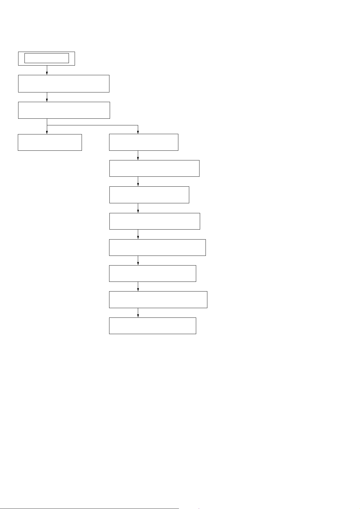
Note: This set can be disassemble according to the following sequence.
SET
2-1. SUB PANEL (FL-U) ASSY
(Page 11)
2-2. CD MECHANISM BLOCK
(Page 11)
2-3. MAIN BOARD
(Page 12)
2-4. SERVO BOARD
(Page 12)
2-5. CHASSIS (T) SUB ASSY
(Page 13)
2-6. ROLLER ARM ASSY
(Page 13)
2-7. CHASSIS (OP) ASSY
(Page 14)
1. CHUCKING ARM SUB ASSY
(SUPPLEMENT-1 Page 1)
2. SLED MOTOR ASSY
(SUPPLEMENT-1 Page 2)
3. OPTICAL PICK-UP SECTION
(SUPPLEMENT-1 Page 3)
10
4. OPTICAL PICK-UP
(SUPPLEMENT-1 Page 3)
Note: Follow the disassembly procedure in the numerical order given.
s
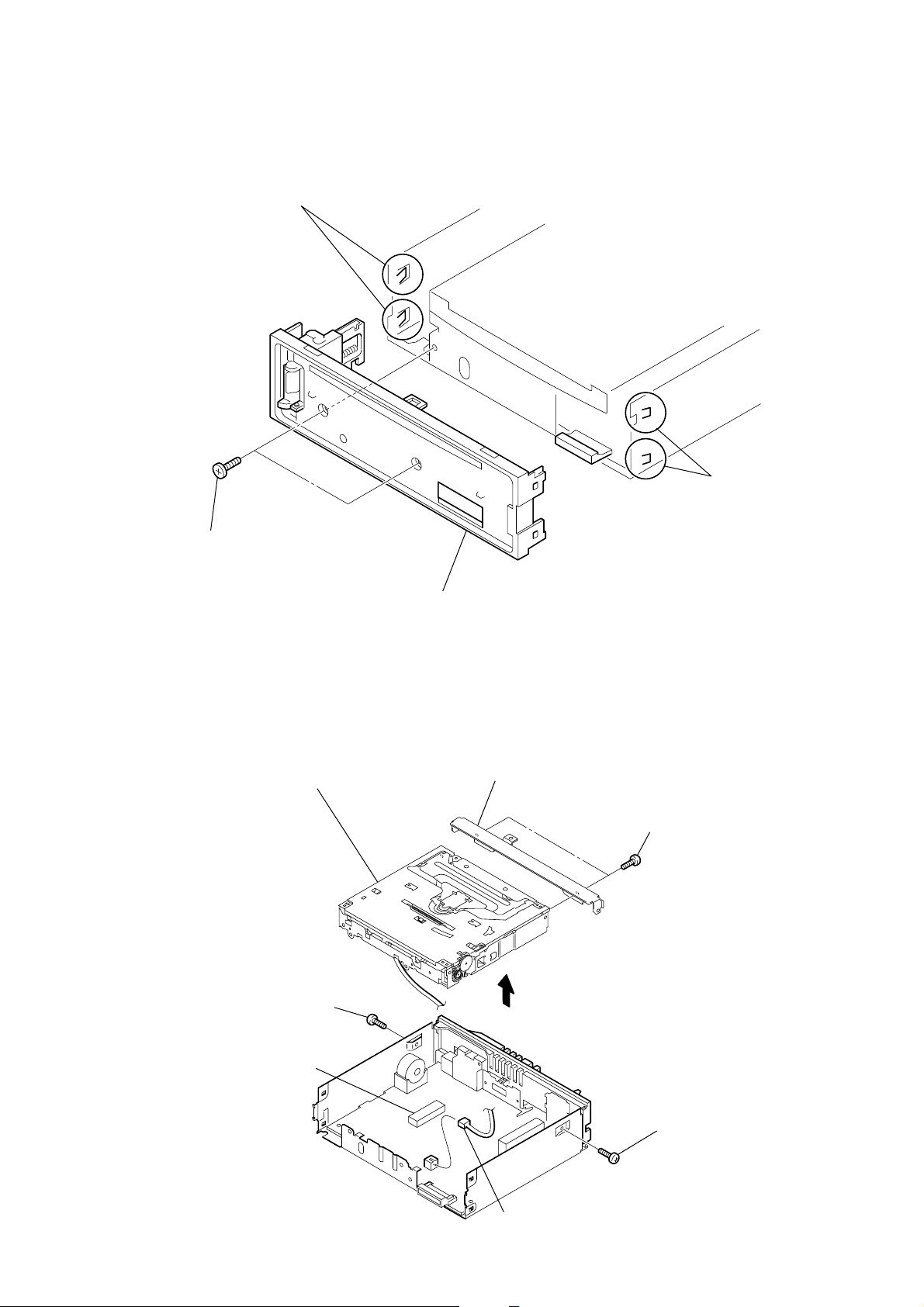
2-1. SUB PANEL (FL) ASSY
3
two claws
CDX-GT41UW/GT410U/GT460U/GT460US
2
two claw
1
two
screws
(+PTT 2.6
×
6)
2-2. CD MECHANISM BLOCK
8
2
screw
(+PTT 2.6
×
CD mechanism block
6)
4
sub panel (FL-U) assy
7
bracket (CD)
3
6
two
(+PTT 2.6
screws
×
4)
4
CN350
5
CN352 (3P)
1
screw
(+PTT 2.6
×
6)
11
CDX-GT41UW/GT410U/GT460U/GT460US
)
)
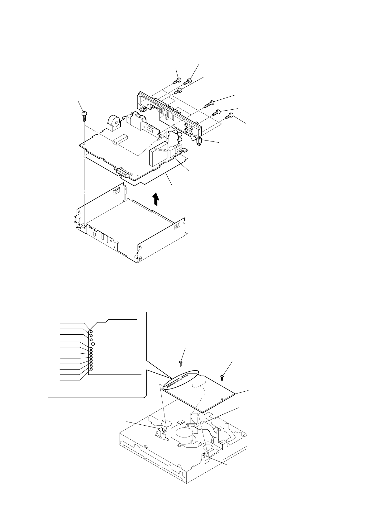
2-3. MAIN BOARD
2
two
screws
(+PTT 2.6
1
three
screws
(+BTT 2.6
×
5)
insulating sheet
3
×
8)
4
5
0
MAIN board
two
screws
(+PTT 2.6
two
screws
(+P 2.6
9
×
10)
×
8)
6
7
heat sink
two
screws
(+PTT 2.6
screw
(+P 2.6
8
screw
(+PTT 2.6
×
×
10)
10)
×
10
2-4. SERVO BOARD
WHT
RED
BLK
WHT
RED
BLK
RED
ORG
BLU
YEL
GRY
1
Remove the eleven solders.
SERVO board
claw
2
toothed lock
(M 1.7
×
2.5)
screw
3
claw
toothed lock
(M 1.7
4
optical pick-up (16 core
(CN1)
screw
×
2.5)
5
SERVO board
12
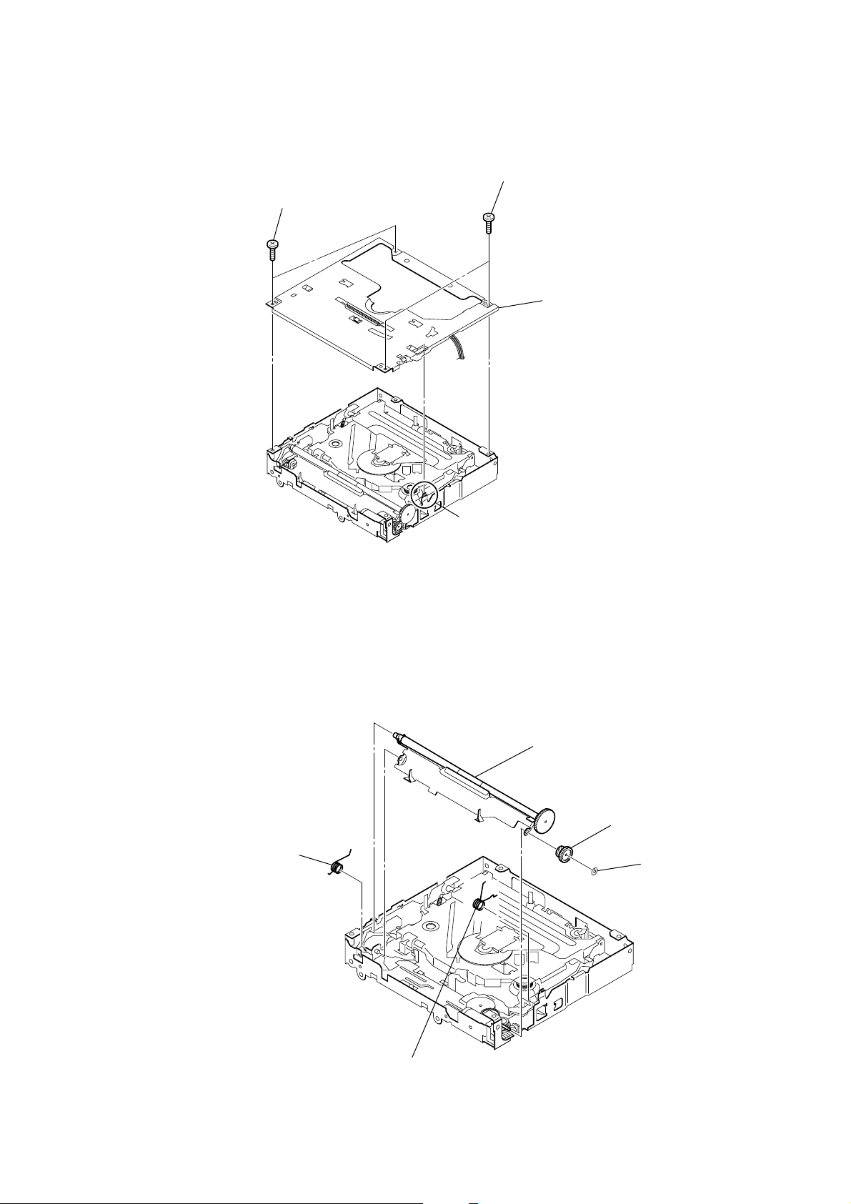
2-5. CHASSIS (T) SUB ASSY
1
two precision
(+P 1.7
×
2.2)
screws
CDX-GT41UW/GT410U/GT460U/GT460US
2
two precision
(+P 1.7
4
screws
×
2.2)
chassis (T) sub assy
2-6. ROLLER ARM ASSY
1
spring (RAL)
3
claw
5
roller arm assy
4
gear (RA1)
3
washer
2
spring (RAR)
13
CDX-GT41UW/GT410U/GT460U/GT460US
)
Ver. 1.2
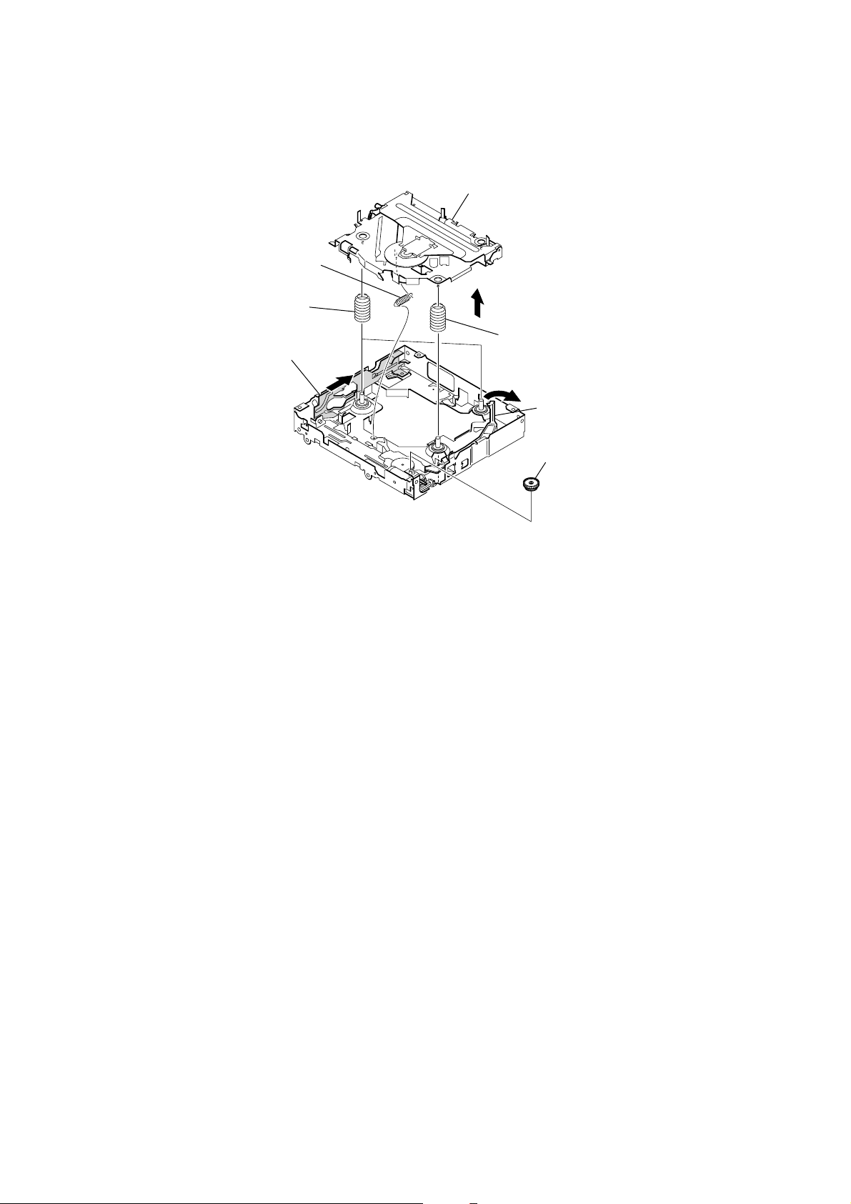
2-7. CHASSIS (OP) ASSY
1
tension spring (KF)
7
coil spring (damper) (natural)
4
slider (R)
6
chassis (OP) assy
5
8
coil spring (damper) (green
3
lever (D)
2
gear (LE1)
14
 Loading...