

Sony CDX-C880R Service manual
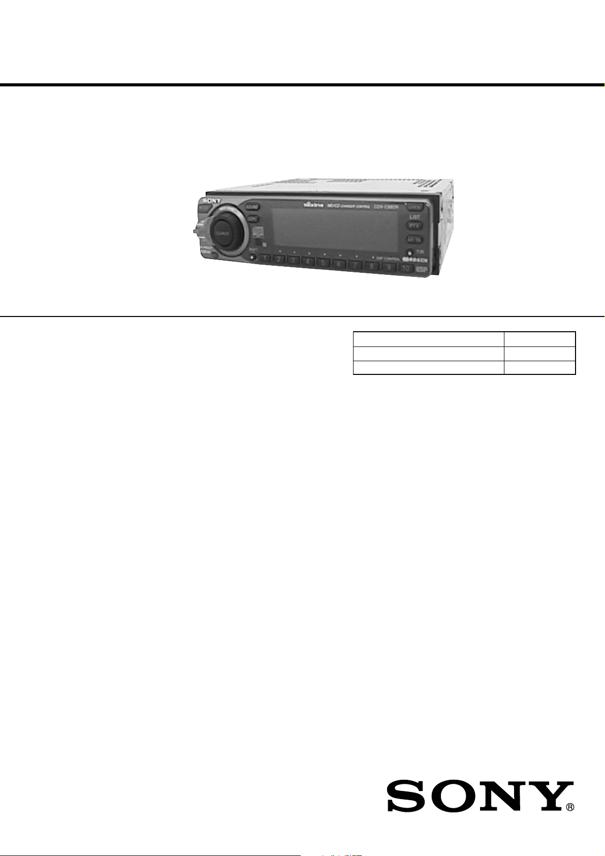
CDX-C880R
SERVICE MANUAL
Ver 1.1 2001. 08
SPECIFICATIONS
AEP Model
UK Model
Model Name Using Similar Mechanism CDX-C780R
CD Drive Mechanism Type MG-363S-121
Optical Pick-up Name KSS-521A
CD player section
System Compact disc digital audio
system
Signal-to-noise ratio 100 dB
Frequency response 10 - 20,000 Hz
Wow and flutter Below measurable limit
Tuner section
FM
Tuning range 87.5 - 108.0 MHz
Aerial terminal External aerial connector
Intermediate frequency 10.7 MHz
Usable sensitivity 8 dBf
Selectivity 75 dB at 400 kHz
50 dB at 200 kHz
Signal-to-noise ratio 65 dB (stereo),
68 dB (mono)
Harmonic distortion at 1 kHz
0.7% (stereo),
0.4% (mono)
Separation 35 dB at 1 kHz
Frequency response 30 - 15,000 Hz
MW/LW
Tuning range MW : 531 - 1,602 kHz
LW : 153 - 281 kHz
Aerial terminal External aerial connector
Intermediate frequency 10.71 MHz / 450 kHz
Sensitivity MW : 30 µV
LW : 50 µV
Power amplifier section
Outputs Speaker outputs
(sure seal connectors)
Speaker impedance 4 - 8 ohms
Maximum power output 45 W × 4 (at 4 ohms)
General
Outputs Line outputs (4)
Power aerial relay
control lead
Power amplifier control
lead
Telephone ATT control
lead
Tone controls Bass ±8 dB at 100 Hz
Treble ±8 dB at 10 kHz
Power requirements 12 V DC car battery
(negative ground)
Dimensions Approx. 178 × 50 × 182 mm
(w/h/d)
Mounting dimension Approx. 182 × 53 × 163 mm
(w/h/d)
Mass Approx. 1.5 kg
Supplied accessories Rotary commander (RM-X4V) (1)
Microphone (1)
Parts for installation and
connections (1 set)
Front panel case (1)
Design and specifications are subject to change without
notice.
9-926-037-12
2001H0400-1
© 2001. 8
FM/MW/LW COMPACT DISC PLAYER
Sony Corporation
e Vehicle Company
Shinagawa Tec Service Manual Production Group

SERVICE NOTE
TABLE OF CONTENTS
CAUTION
Use of controls or adjustments or performance of procedures other than those specified herein may result in hazardous radiation exposure.
Notes on Chip Component Replacement
• Never reuse a disconnected chip component.
• Notice that the minus side of a tantalum capacitor may be dam-
aged by heat.
NOTES ON HANDLING THE OPTICAL PICK-UP BLOCK
OR BASE UNIT
The laser diode in the optical pick-up block may suffer electrostatic
breakdown because of the potential difference generated by the
charged electrostatic load, etc. on clothing and the human body.
During repair, pay attention to electrostatic breakdown and also use
the procedure in the printed matter which is included in the repair
parts.
The flexible board is easily damaged and should be handled with
care.
NOTES ON LASER DIODE EMISSION CHECK
The laser beam on this model is concentrated so as to be focused on
the disc reflective surface by the objective lens in the optical pickup block. Therefore, when checking the laser diode emission, observe from more than 30 cm away from the objective lens.
NOTES ON PICK-UP FLEXIBLE BOARD
The pick-up flexible board in this set is secured to the optical pickup with an adhesive tape. Once the tape is removed, an adhering
force becomes weak, and it cannot be reused.
Therefore, if the optical pick-up is replaced, replace also the pickup flexible board with a new one.
SAFETY-RELATED COMPONENT WARNING!!
COMPONENTS IDENTIFIED BY MARK ! OR DOTTED LINE
WITH MARK ! ON THE SCHEMATIC DIAGRAMS AND IN
THE PARTS LIST ARE CRITICAL TO SAFE OPERATION.
REPLACE THESE COMPONENTS WITH SONY PARTS WHOSE
P ART NUMBERS APPEAR AS SHOWN IN THIS MANU AL OR
IN SUPPLEMENTS PUBLISHED BY SONY.
1. GENERAL
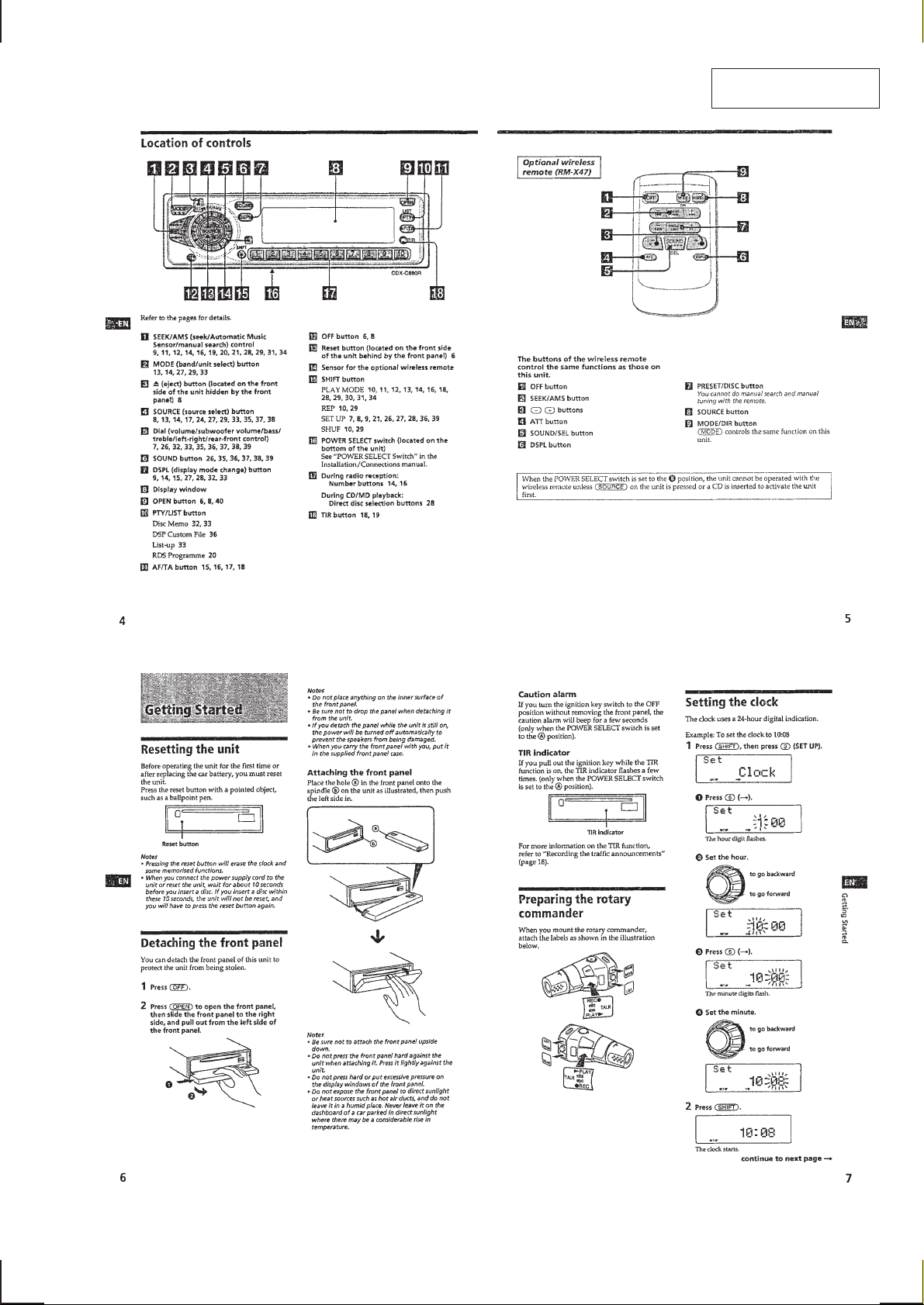
Location of Controls................................................................ 3
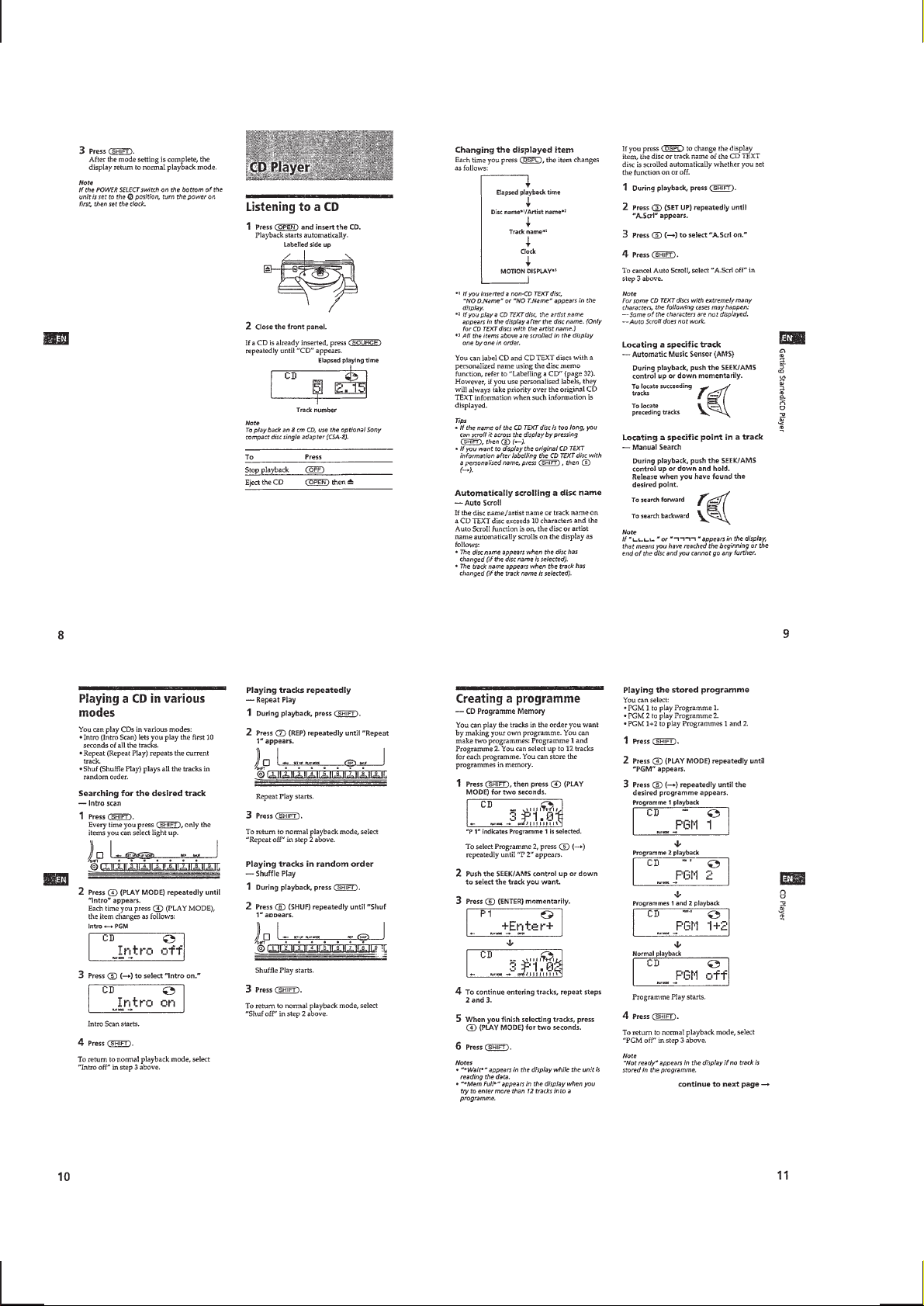
Getting Started......................................................................... 3
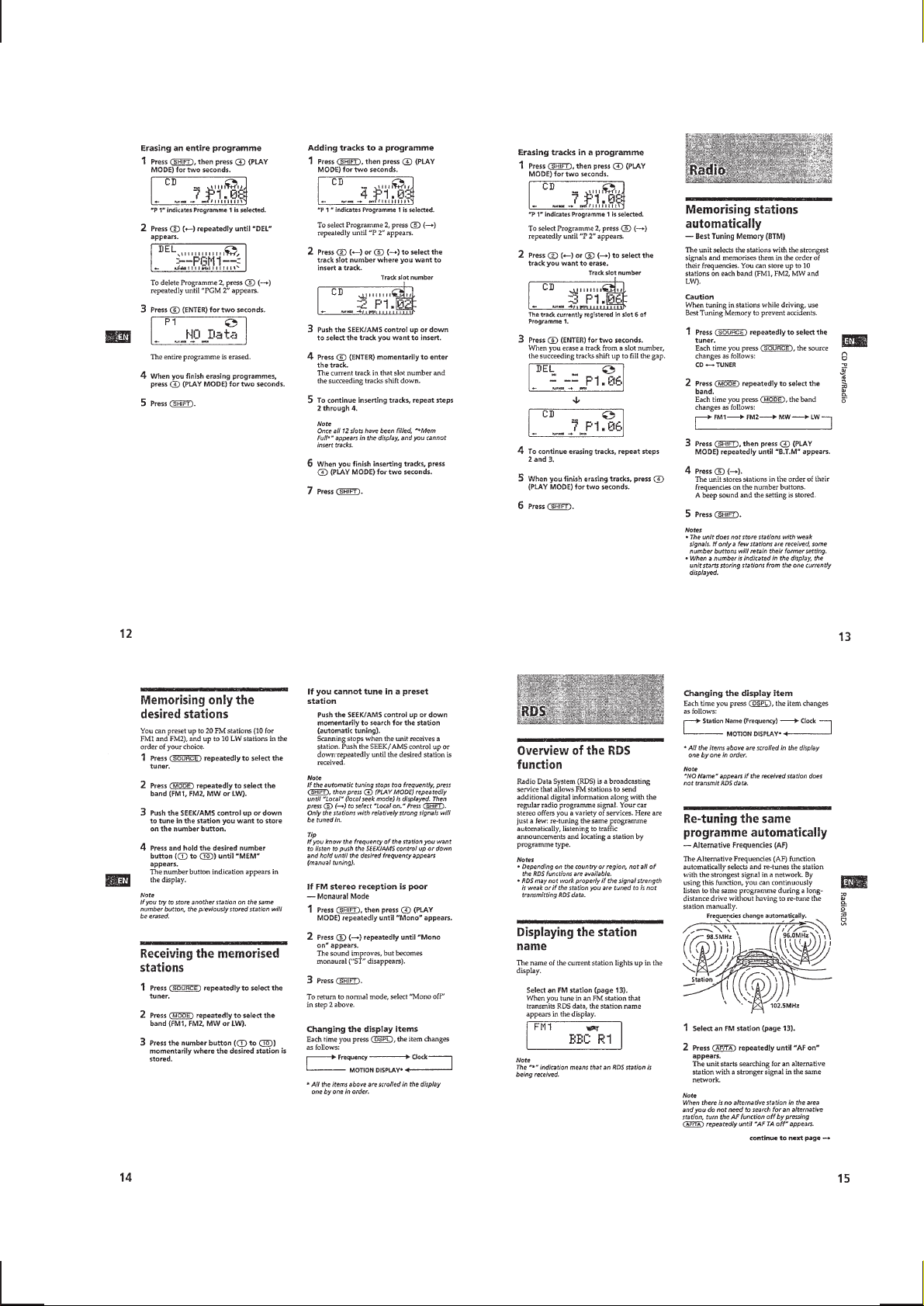
CD Player ................................................................................ 4
Radio ....................................................................................... 5
RDS ......................................................................................... 5
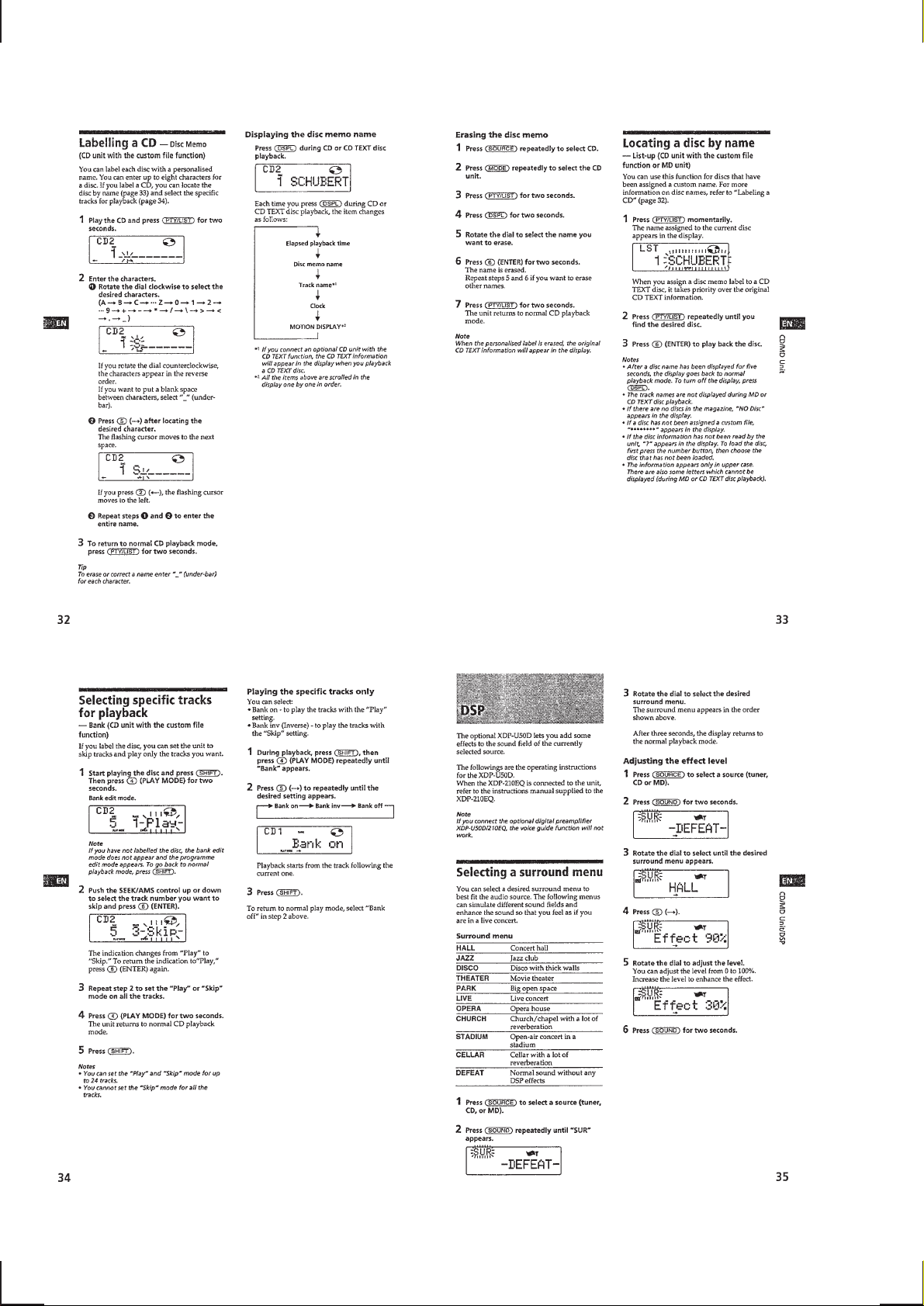
Voice Driver.............................................................................7
Voice Memo.............................................................................7
Other Functions .......................................................................8
CD/MD Unit............................................................................ 8
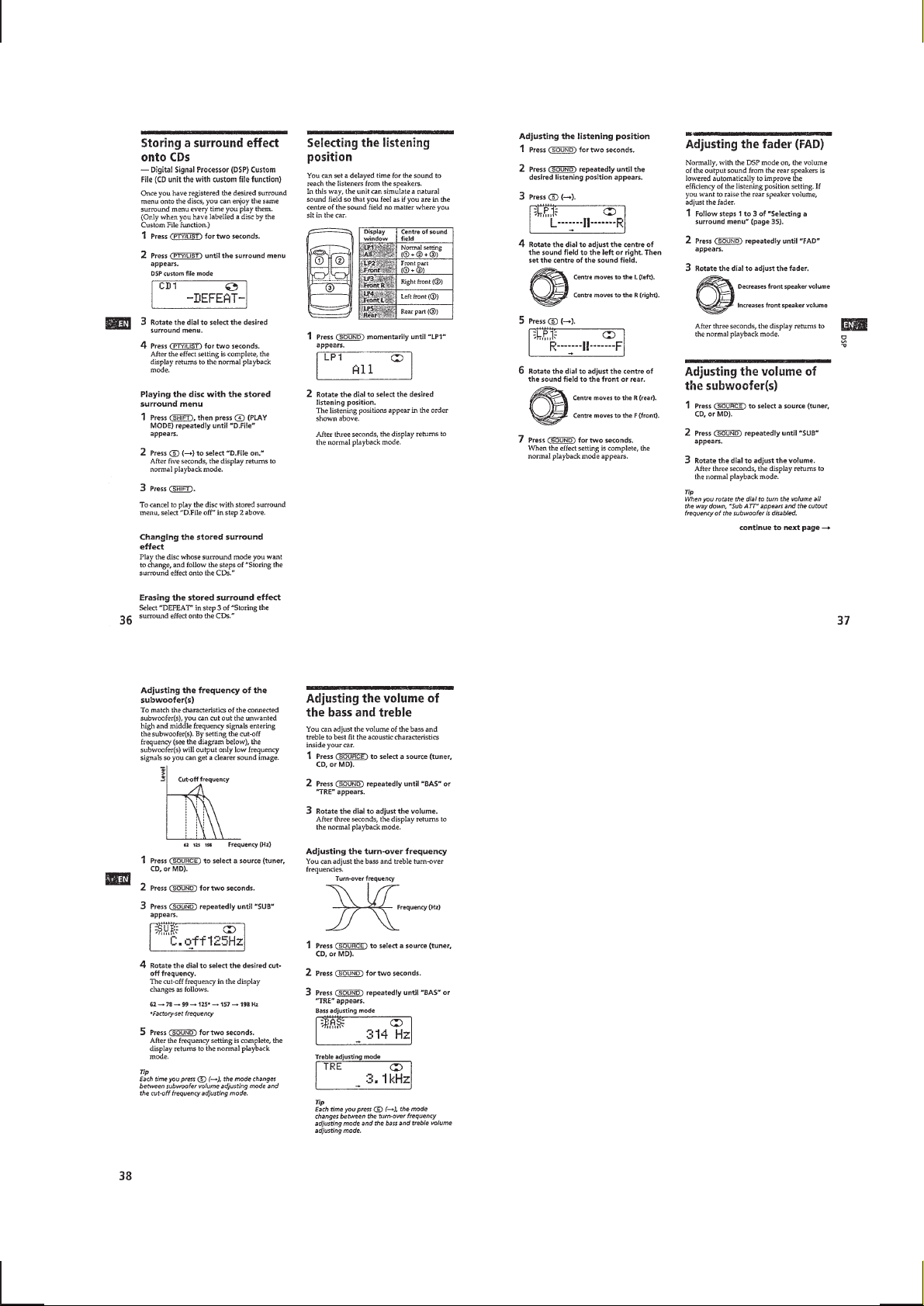
DSP........................................................................................ 10
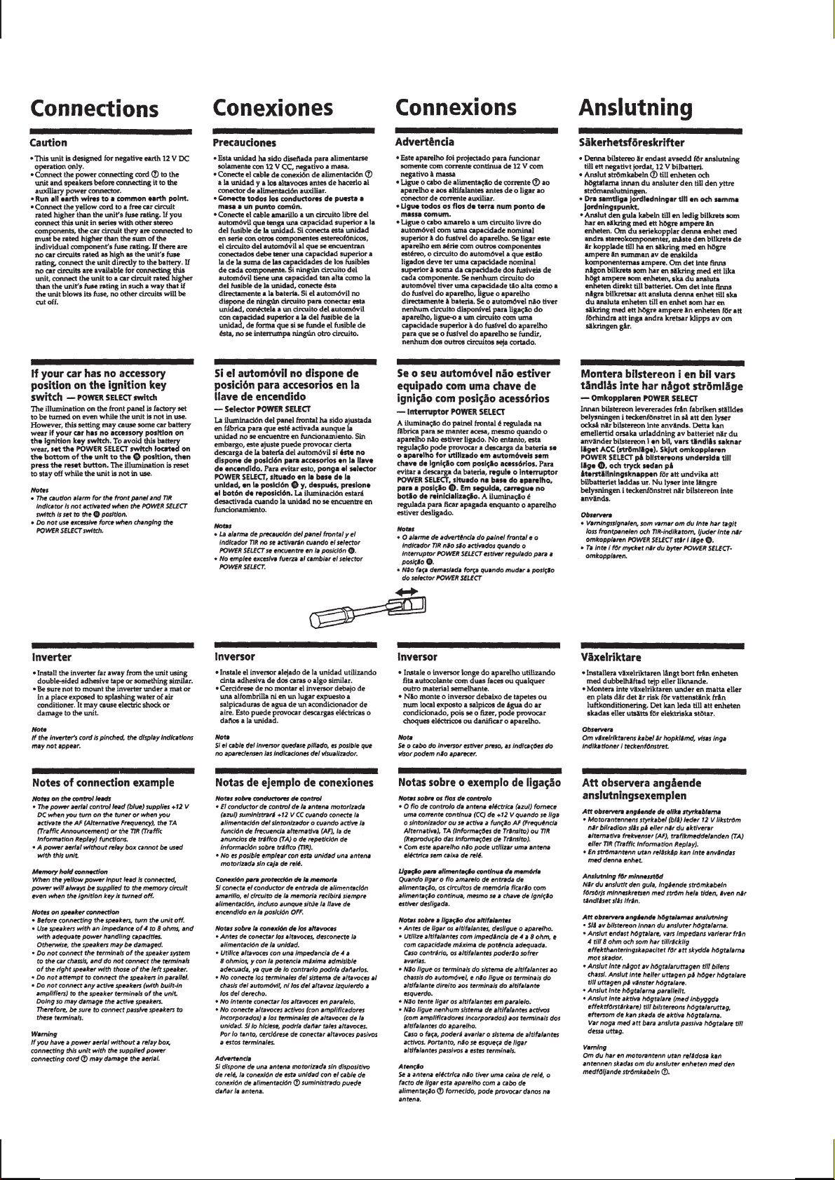
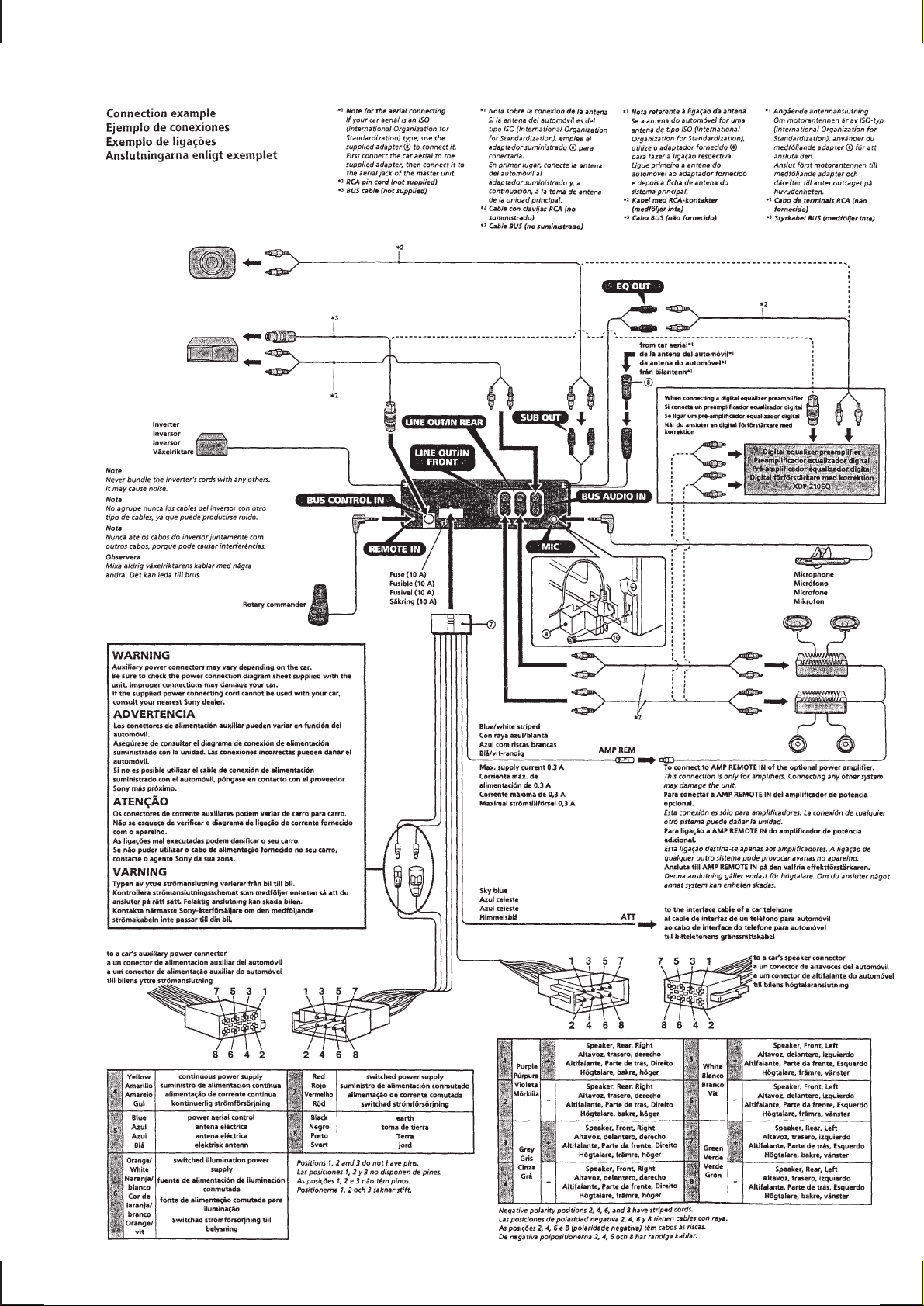
Connections ...........................................................................12
2. DISASSEMBLY
2-1. Cover ................................................................................. 14
2-2. Front Panel Assy ............................................................... 14
2-3. Sub Panel Assy.................................................................. 15
2-4. Mechanism Block ............................................................. 15
2-5. Main Board ....................................................................... 16
2-6. Heat Sink ........................................................................... 16
2-7. Chassis (T) Sub Assy ........................................................ 17
2-8. Lever Assy ......................................................................... 17
2-9. Servo Board....................................................................... 18
2-10. Roller Assy........................................................................ 18
2-11. Chassis (OP) (O/S) Assy ................................................... 19
2-12. Optical Pick-up Block ....................................................... 19
3. ELECTRICAL ADJUSTMENTS
CD Section ............................................................................ 20
Tuner Section.........................................................................20
4. DIAGRAMS
4-1. IC Pin Descriptions ........................................................... 24
4-2. Circuit Boards Location .................................................... 32
4-3. Block Diagram –CD Section–........................................... 33
4-4. Block Diagram –Main Section–........................................ 35
4-5. Block Diagram –Display Section–.................................... 37
4-6. Printed Wiring Boards –CD Mechanism Section–............ 39
4-7. Schematic Diagram –CD Mechanism Section– ................ 43
4-8. Schematic Diagram –Main Section–................................. 48
4-9. Printed Wiring Boards –Main Section– ............................ 53
4-10. Printed Wiring Boards –Display Section– ........................ 57
4-11. Schematic Diagram –Display Section–............................. 61
4-12. Printed Wiring Board –CSV Section–............................... 64
4-13. Schematic Diagram –CSV Section– ................................. 67
5. EXPLODED VIEWS
5-1. Chassis Section ................................................................. 76
5-2. Front Panel Section ........................................................... 77
5-3. CD Mechanism Section (1) ............................................... 78
5-4. CD Mechanism Section (2) ............................................... 79
5-5. CD Mechanism Section (3) ............................................... 80
6. ELECTRICAL PARTS LIST ........................................ 81
– 2 –
SECTION 1
GENERAL
This section is extracted
from instruction manual.
– 3 –
– 4 –
– 5 –
– 6 –
– 7 –
– 8 –
– 9 –
– 10 –
– 11 –
– 12 –
– 13 –
SECTION 2
DISASSEMBLY
Note : Follow the disassembly procedure in the numerical order given.
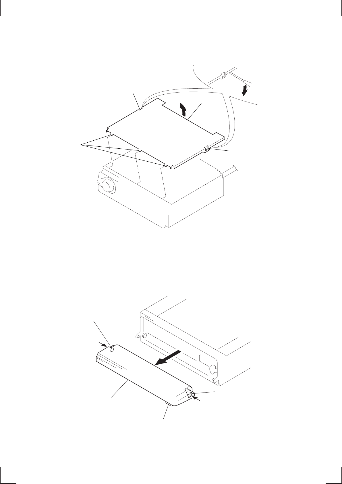
2-1. COVER
1
claw
3
claws
4
cover
2
claw
2-2. FRONT PANEL ASSY
3
Push the bearing (L).
4
front panel assy
1
Push the button (open).
2
Push the bearing (R).
– 14 –
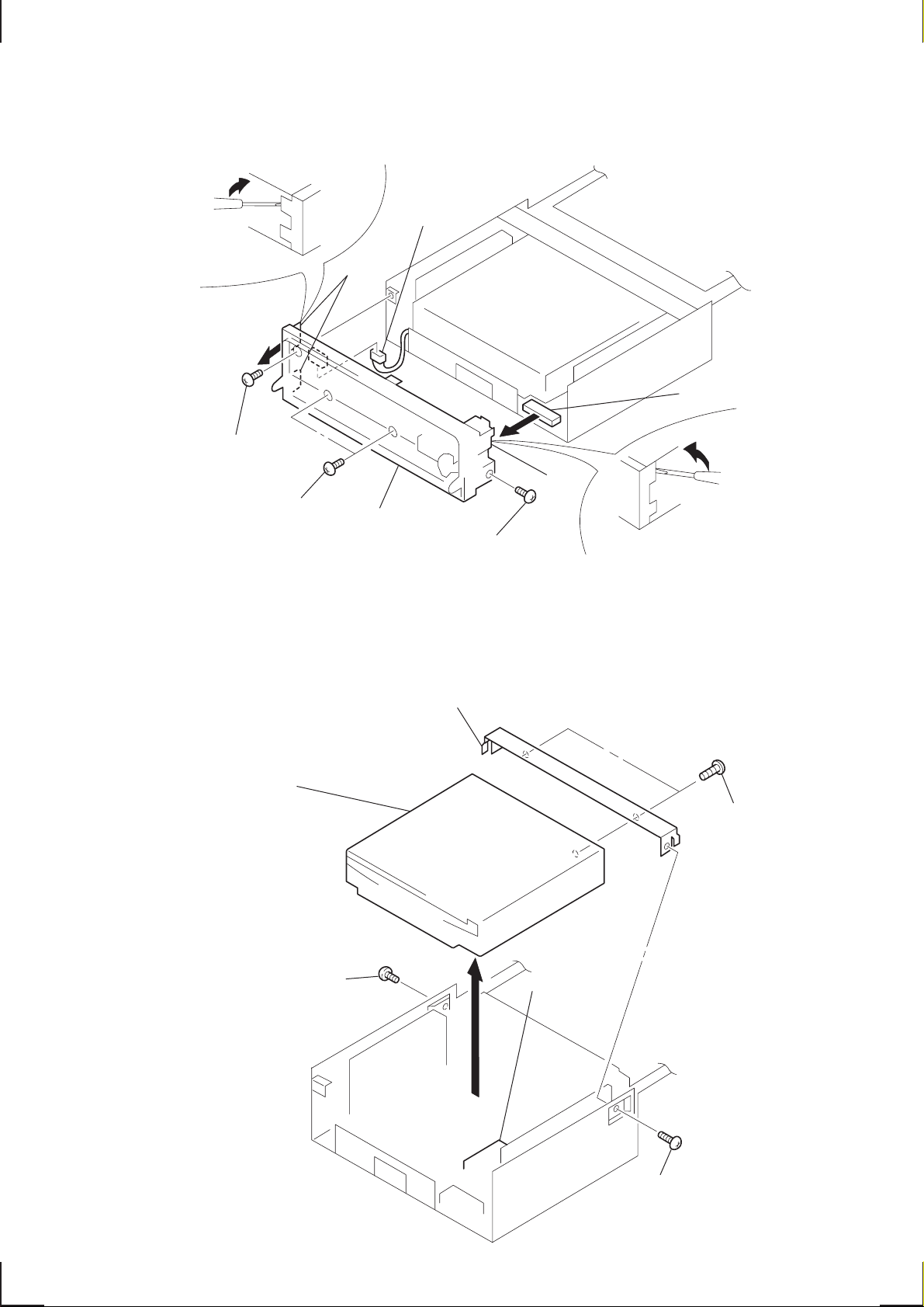
6
3
PTT 2.6x6
8
sub panel assy
6
CN801
5
claw
1
PTT 2.6x6
2
PTT 2.6x6
4
claws
7
CN804
2-3. SUB PANEL ASSY
2-4. MECHANISM BLOCK
4
mechanism block
1
B 2.6x3
6
bracket (mechanism deck)
3
CN401
5
PTT 2.6x
– 15 –
2
B 2.6x3
0
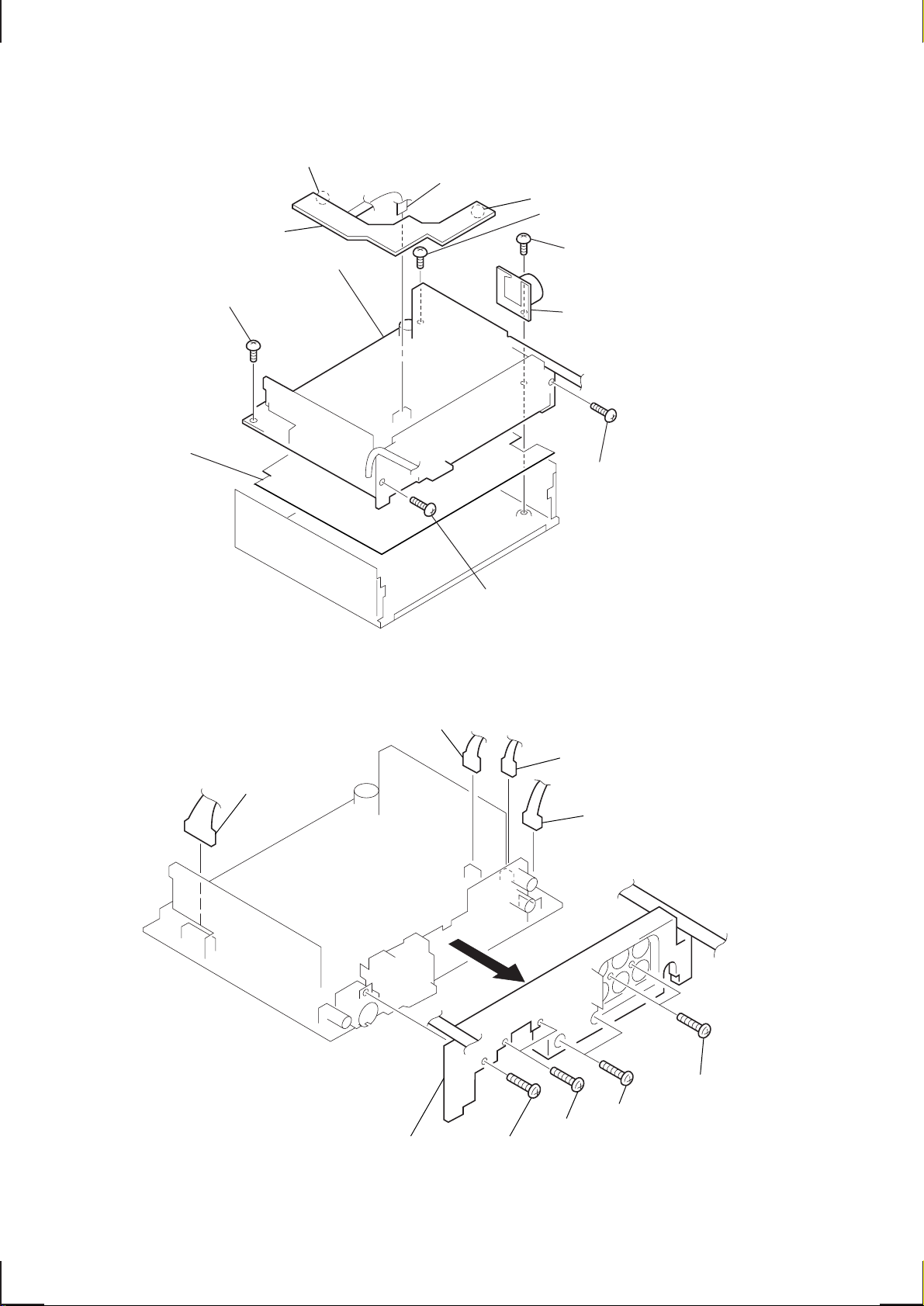
2-5. MAIN BOARD
!™
CSV board
6
(PTT 2.6x6)
8
sheet (insulating)
!¡
claw
7
MAIN board
ground point screw
9
CN901
0
claw
5
ground point screw
(PTT 2.6x6)
3
ground point screw
(PTT 2.6x6)
4
bracket (super capacitor)
2
PTT 2.6x10
1
PTT 2.6x10
2-6. HEAT SINK
4
CN603
9
heat sink
2
CN203
8
PTT 2.6x10
3
CN10
1
CN202
7
PTT 2.6x10
6
PTT 2.6x10
5
PTT 2.6x1
– 16 –
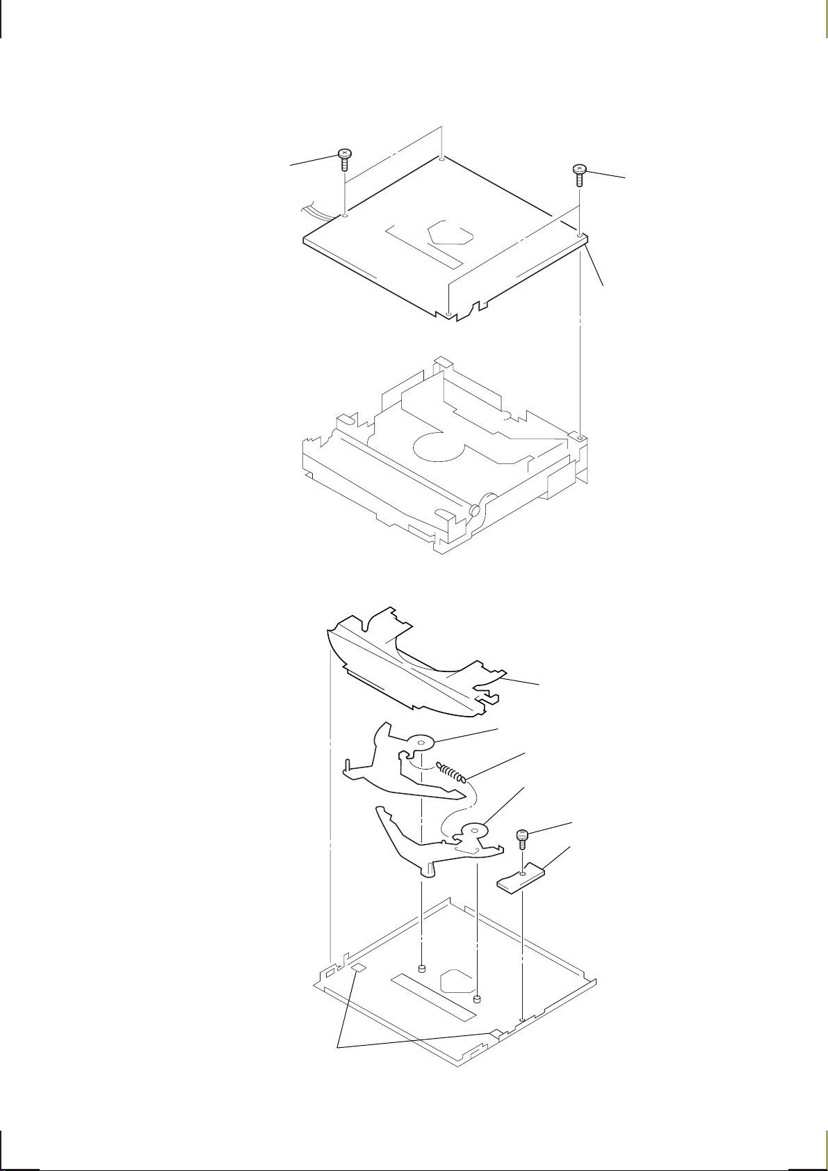
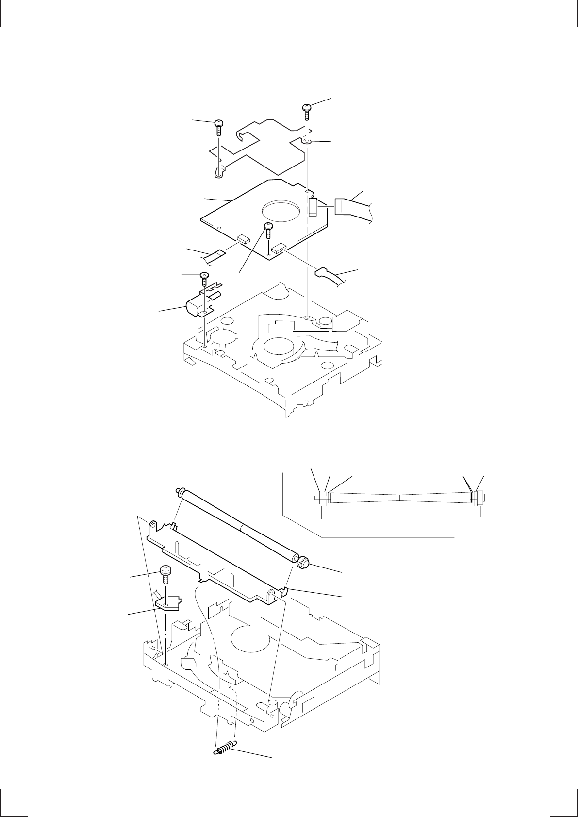
2-7. CHASSIS (T) SUB ASSY
1
P 2x3
2
P 2x3
3
chassis (T) sub assy
2-8. LEVER ASSY
5
6
lever (R) assy
3
tension spring (LR)
7
lever (L) assy
guide (disc)
1
PS 2x4
2
DISC IN SW board
4
claws
– 17 –
2-9. SERVO BOARD
9
loading motor assy
2
PS 2x5
0
SERVO board
4
CN4
8
P 2x3
6
PS 2x4
1
PS 2x5
3
heat sink
5
7
CN5
CN2
2-10. ROLLER ASSY
• When installing, take note of the positions
arm (roller) and washers. (Fig. 1)
4
PS 2x3
5
LOAD SW board
washer
arm washer
3
roller assy
2
arm (roller)
armwashers
Fig. 1
1
tension spring (RA)
– 18 –
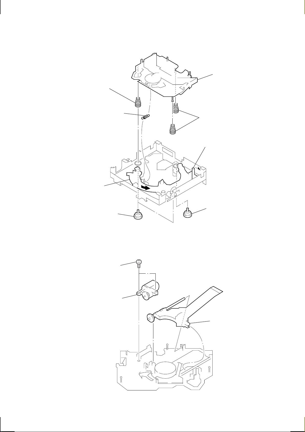
2-11. CHASSIS (OP) (O/S) ASSY
8
compression spring (FL)
1
tension spring (angle)
5
Turn loading ring in the
direction of the arrow.
6
chassis (OP) (O/S) assy
7
compression spring (FL)
4
Fit lever (D) in the
direction of the arrow.
2
damper (T)
2-12. OPTICAL PICK-UP BLOCK
1
P 2x3
2
sled motor assy
3
damper (T)
3
optical pick-up block
– 19 –
SHUF
REG
SECTION 3
ELECTRICAL ADJUSTMENTS
CD SECTION
CD section adjustments are done automatically in this set.
TUNER SECTION
0 dB = 1 µV
Cautions during repair
When the tuner unit is defective, replace it by a new one
because its internal block is difficult to repair.
TEST MODE
This set have the test mode function. In the test mode, FM Auto
Scan/Stop Level and MW Auto Scan/Stop Level adjustments can
be performed easier than it in ordinary procedure.
<Set the Test Mode>
1. Set the “OFF” mode.
2. Push the preset 4 button.
3. Push the preset 5 button.
4. Press the preset 1 button for more than two seconds.
5. Then the display indicates all lights, the test mode is set.
<Release the Test Mode>
1. Push the OFF button.
Note on Adjustment
The adjustments of tuner section, should be performed according
to the following sequence.
1. FM Auto Scan/Stop Level Adjustment
2. FM Stereo Separation Adjustment (WIDE)
3. FM Stereo Separation Adjustment (NARROW)
4. FM RDS S-Meter Adjustment
5. MW Auto Scan/Stop Le vel Adjustment
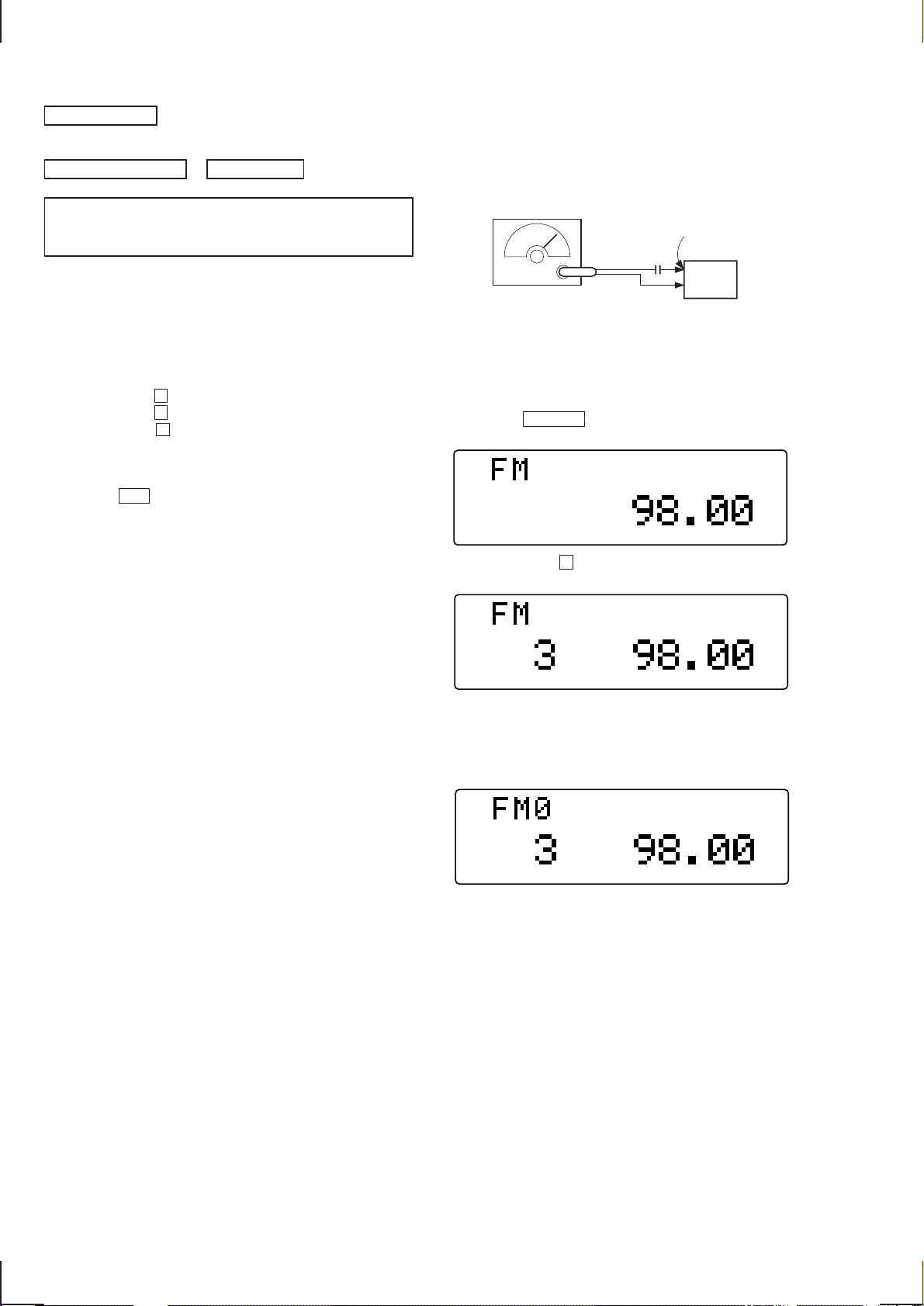
FM Auto Scan/Stop Level Adjustment
Setting :
SOURCE button : FM
FM RF signal
generator
antenna
µ
terminal
F
0.01
Carrier frequency : 98.00 MHz
Output level : 22 dB (12.6 µV)
Mode : mono
Modulation : 1 kHz, 22.5 kHz deviation (30%)
Procedure :
1. Set to the test mode.
2. Push the SOURCE button and set to FM.
Display
SHUF
REG
3. Push the preset 3 button.
Display
SHUF
REG
set
4. Adjust with the volume RV2 on TU10 so that the “FM”
indication turns to “FM0” indication on the display window.
But, in case of already indicated “FM0”, turn the RV2 so that
put out light “0” indication and adjustment.
Display
Adjustment Location : See page 23.
– 20 –
Ver 1.1
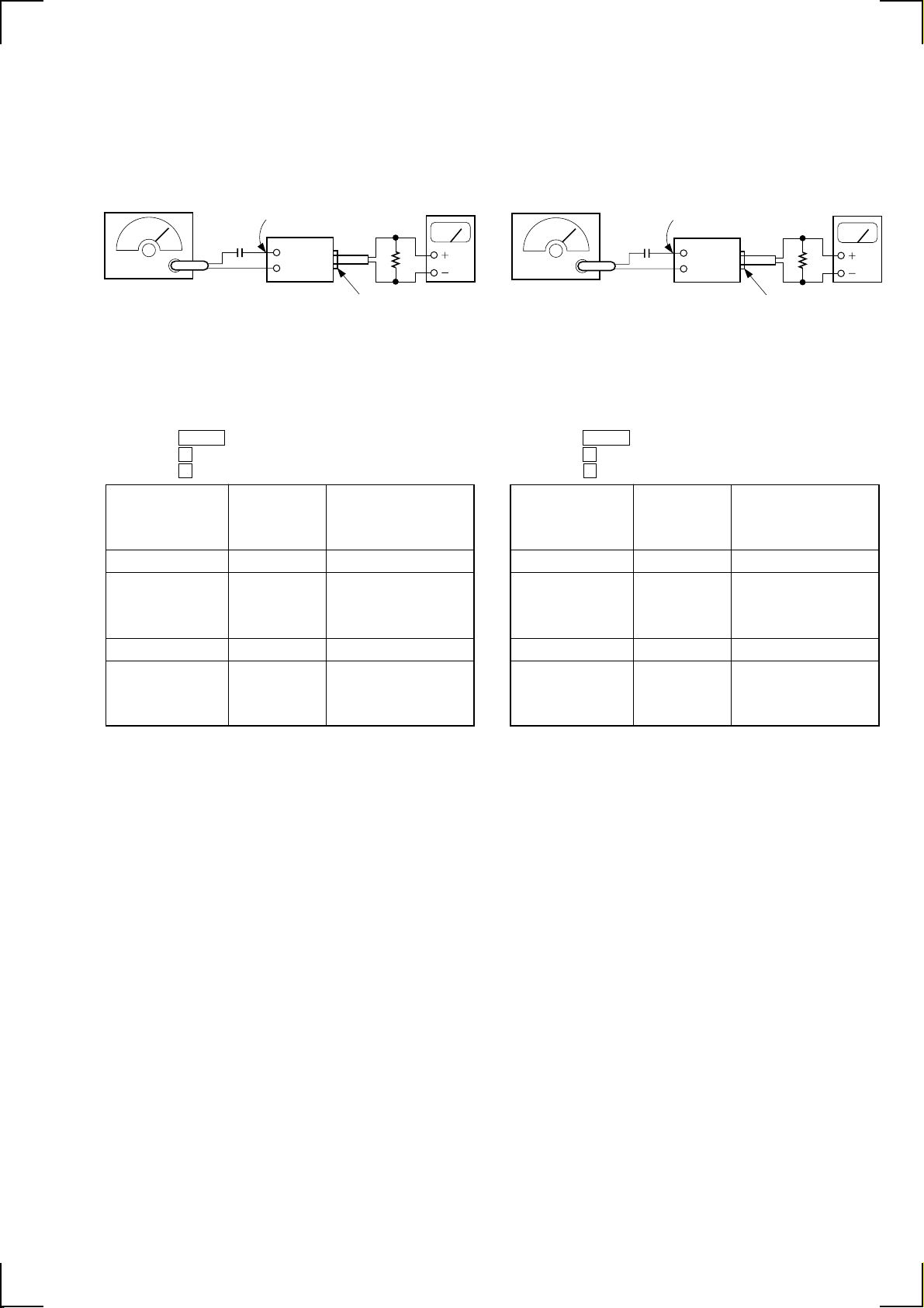
FM Stereo Separation Adjustment (WIDE)
Setting :
SOURCE button: FM
FM RF signal
generator
0.01 µF
Carrier frequency : 98.00 MHz
Output level : 70 dB (3.2 mV)
Mode : stereo
Modulation : main : 1 kHz, 20 kHz deviation (26.5%)
sub : 1 kHz, 20 kHz deviation (26.5%)
19 kHz pilot : 7.5 kHz deviation (10%)
antenna
terminal
set
10 k Ω
LINE OUT REAR
Procedure :
1. Set to the test mode.
2. Push the SHIFT button.
3. Push the 4 button three times.
4. Push the 5 button once and set to WIDE mode.
FM stereo
signal generator
output channel
Level meter Level meter
connection reading (dB)
L-CH L-CH A
B
R-CH L-CH Adjust RV3 on TU10 for
minimum reading.
R-CH R-CH C
D
L-CH R-CH Adjust RV3 on TU10 for
minimum reading.
level meter
FM Stereo Separation Adjustment (NARROW)
Setting :
SOURCE button : FM
FM RF signal
generator
0.01 µF
Carrier frequency : 98.00 MHz
Output level : 70 dB (3.2 mV)
Mode : stereo
Modulation : main : 1 kHz, 20 kHz deviation (26.5%)
sub :1 kHz, 20 kHz deviation (26.5%)
19 kHz pilot : 7.5 kHz deviation (10%)
antenna
terminal
set
10 k Ω
LINE OUT REAR
Procedure :
1. Set to the test mode.
2. Push the SHIFT button.
3. Push the 4 button three times.
4. Push the 5 button twice and set to NARROW mode.
FM stereo
signal generator
output channel
Level meter Level meter
connection reading (dB)
L-CH L-CH A
B
R-CH L-CH Adjust RV4 on TU10 for
minimum reading.
R-CH R-CH C
D
L-CH R-CH Adjust RV4 on TU10 for
minimum reading.
level meter
L-CH stereo separation : A – B
R-CH stereo separation : C – D
The separations of both channels should be equal.
Specification : Separation more than 24 dB
Adjustment Location : See page 23.
L-CH stereo separation : A – B
R-CH stereo separation : C – D
The separations of both channels should be equal.
Specification : Separation more than 18 dB
Adjustment Location : See page 23.
– 21 –
 Loading...