

Page 1
4-147-228-12(1)
The software of this system may be updated in the future. To find out details on any
available updates, please visit: http://esupport.sony.com
(1)
Sony Corporation Printed in Malaysia
BD/DVD Home Theatre System
Operating Instructions
BDV-T20W / E500W
© 2009 Sony Corporation
Page 2
WARNING
To reduce the risk of fire or electric
shock, do not expose this apparatus to
rain or moisture.
Do not install the appliance in a confined space, such
as a bookcase or built-in cabinet.
To reduce the risk of fire, do not cover the ventilation
opening of the apparatus with newspapers, tablecloths,
curtains, etc. Do not place the naked flame sources
such as lighted candles on the apparatus.
To reduce the risk of fire or electric shock, do not
expose this apparatus to dripping or splashing, and do
not place objects filled with liquids, such as vases, on
the apparatus.
Do not expose batteries or apparatus with batteryinstalled to excessive heat such as sunshine, fire or the
like.
To prevent injury, this apparatus must be securely
attached to the floor/wall in accordance with the
installation instructions.
Excessive sound pressure from earphones and
headphones can cause hearing loss.
Indoor use only.
CAUTION
The use of optical instruments with this product will
increase eye hazard. As the laser beam used in this BD/
DVD Home Theatre System is harmful to eyes, do not
attempt to disassemble the cabinet.
Refer servicing to qualified personnel only.
Precautions
On power sources
• The unit is not disconnected from the mains as long
as it is connected to the AC outlet, even if the unit
itself has been turned off.
• As the main plug is used to disconnect the unit from
the mains, connect the unit to an easily accessible AC
outlet. Should you notice an abnormality in the unit,
disconnect the main plug from the AC outlet
immediately.
For the customers in the U.S.A.
This symbol is intended to alert the user to
the presence of uninsulated “dangerous
voltage” within the product’s enclosure that
may be of sufficient magnitude to constitute
a risk of electric shock to persons.
This symbol is intended to alert the user to
the presence of important operating and
maintenance (servicing) instructions in the
literature accompanying the appliance.
Owner’s Record
The model and serial numbers are located at the rear
exterior of the co ntrol unit. Record the serial num ber in
the space provided below. Refer to them whenever you
call upon your Sony dealer regarding this product.
Model No. BDV-T20W/BDV-E500W
Serial No.______________
This label is located on the laser protective housing
inside the enclosure.
This appliance is
classified as a CLASS 1
LASER product. This
marking is loca ted on the
rear exterior.
About the surround amplifier
• The nameplate is located on the side exterior.
• For the customers in the U.S.A.: Date of Manufacture
Marking is located on the bottom exterior.
US
2
The following FCC statement applies only to the
version of this model manufactured for sale in the
USA. Other versions may not comply with FCC
technical regulations.
NOTE:
This equipment has been tested and found to comply
with the limits for a Class B digital device, pursuant to
Part 15 of the FCC Rules. These limits are designed to
provide reasonable protection against harmful
interference in a residential installation. This
equipment generates, uses, and can radiate radio
frequency energy and, if not installed and used in
accordance with the instructions, may cause harmful
interference to radio communications. However, there
is no guarantee that interference will not occur in a
Page 3

particular installation. If this equipment does cause
harmful interference to radio or television reception,
which can be determined by turning the equipment off
and on, the user is encouraged to try to correct the
interference by one or more of the following measures:
– Reorient or relocate the receiving antenna (aerial).
– Increase the separation between the equipment and
receiver.
– Connect the equipment into an outlet on a circuit
different from that to which the receiver is
connected.
– Consult the dealer or an experienced radio/TV
technician for help.
CAUTION
You are cautioned that any changes or modifications
not expressly approved in this manual could void your
authority to operate this equipment.
Important Safety Instructions
1) Read these instructions.
2) Keep these instructions.
3) Heed all warnings.
4) Follow all instructions.
5) Do not use this apparatus near water.
6) Clean only with dry cloth.
7) Do not block any ventilation openings. Install in
accordance with the manufacturer’s instructions.
8) Do not install near any heat sources such as
radiators, heat registers, stoves, or other apparatus
(including amplifiers) that produce heat.
9) Do not defeat the safety purpose of the polarized or
grounding-type plug. A polarized plug has two
blades with one wider than the other. A grounding
type plug has two blades and a third grounding
prong. The wide blade or the third prong are
provided for your safety. If the provided plug does
not fit into your outlet, consult an electrician for
replacement of the obsolete outlet.
10) Protect the power cord from being walked on or
pinched particularly at plugs, convenience
receptacles, and the point where they exit from the
apparatus.
11) Only use attachments/accessories specified by the
manufacturer.
12) Use only with the cart, stand, tripod, bracket, or
table specified by the manufacturer, or sold with
the apparatus. When a cart is used, use caution
when moving the cart/apparatus combination to
avoid injury from tip-over.
13) Unplug this apparatus during lightning storms or
when unused for long periods of time.
14) Refer all servicing to qualified service personnel.
Servicing is required when the apparatus has been
damaged in any way, such as power-supply cord or
plug is damaged, liquid has been spilled or objects
have fallen into the apparatus, the apparatus has
been exposed to rain or moisture, does not operate
normally, or has been dropped.
ENERGY STAR
registered mark.
As an ENERGY STAR
Sony Corporation has determined
that this product meets the ENERGY
®
STAR
efficiency.
®
is a U.S.
®
partner,
guidelines for energy
For the wireless transceiver
(EZW-RT10/EZW-RT10A)
This equipment must not be co-located or operated in
conjunction with any other antenna or transmitter.
This equipment complies with FCC radiation exposure
limits set forth for uncontrolled equipment and meets
the FCC radio frequency (RF) Exposure Guidelines in
Supplement C to OET65.
This equipment should be installed and operated with
at least 20cm and more between the radiator and
person’s body (excluding extremities: hands, wrists,
feet and ankles).
Notice for the customers in
Canada
For the wireless transceiver
(EZW-RT10/EZW-RT10A)
This Class B d igital apparatus complies with Canadian
ICES-003.
This device complies with RSS-Gen of IC Rules.
Operation is subject to the following two conditions:
(1) this device may not cause interference, and (2) this
device must accept any interference, including
interference that may cause undesired operation of this
device.
US
3
Page 4

This equipment complies with IC radiation exposure
limits set forth for uncontrolled equipment and meets
RSS-102 of the IC radio frequency (RF) Exposure
rules.
This equipment should be installed and operated with
at least 20cm and more between the radiator and
persons body (excluding extremities: hands, wrists,
feet and ankles).
Copyrights and Trademarks
• This product incorporates copyright protection
technology that is protected by U.S. patents and other
intellectual property rights.
Use of this copyright protection technology must be
authorized by Macrovision, and is intended for home
and other limited viewing uses only unless otherwise
authorized by Macrovision.
Reverse engineering or disassembly is prohibited.
• This system incorporates with Dolby* Digital and
Dolby Pro Logic (II) adaptive matrix surround
decoder and the DTS** Digital Surround System.
* Manufactured under license from Dolby
Laboratories.
“Dolby”, “Pro Logic”, and the double-D
symbol are trademarks of Dolby Laboratories.
** Manufactured under license under U.S. Patent
#’s: 5,451,942; 5,956,674; 5,974,380;
5,978,762; 6,226,616; 6,487,535; 7,392,195;
7,272,567; 7,333,929; 7,212,872 & other U.S.
and worldwide patents issued & pending.
DTS is a registered trademark and the DTS
logos, Symbol, DTS-HD and DTS-HD Master
Audio | Essential are trademarks of DTS, Inc.
© 1996-2008 DTS, Inc. All Rights Reserved.
• This system incorporates High-Definition
Multimedia Interface (HDMI
HDMI, the HDMI logo and High-Definition
Multimedia Interface are trademarks or registered
trademarks of HDMI Licensing LLC.
• Java and all Java-based trademarks and logos are
trademarks or registered trademarks of Sun
Microsystems, Inc.
• “BD-Live” and “BonusView” are trademarks of Bluray Disc Association.
• “Blu-ray Disc” is a trademark.
• “Blu-ray Disc,” “DVD+RW,” “DVD-RW,”
“DVD+R,” “DVD-R,” “DVD VIDEO,” and “CD”
logos are trademarks.
• “BRAVIA” is a trademark of Sony Corporation.
• “AVCHD” and the “AVCHD” logo are trademarks of
Matsushita Electric Industrial Co., Ltd. and Sony
Corporation.
• “S-AIR” and its logo are trademarks of Sony
Corporation.
TM
) technology.
• , “XMB,” and “xross media bar” are trademarks of
Sony Corporation and Sony Computer Entertainment
Inc.
• “PLAYSTATION” is a trademark of Sony Computer
Entertainment Inc.
• “x.v.Color” and “x.v.Color” logo are trademarks of
Sony Corporation.
• “PhotoTV HD” and the “PhotoTV HD” logo are
trademarks of Sony Corporation.
• Other system and product names are generally
trademarks or registered trademarks of the
manufacturers. ™ and ® marks are not indicated in
this document.
US
4
Page 5

About These Operating
About the S-AIR function
Instructions
• The instructions in these Operating
Instructions describe the controls on the
remote. You can also use the controls on the
unit if they have the same or similar names as
those on the remote.
• Icons, such as , listed at the top of each
explanation indicate what kind of disc can be
used with the function being explained.
For details, see “Playable Discs” (page 101).
• In this manual, “disc” is used as a general
reference for the BDs, DVDs, or CDs unless
otherwise specified by the text or illustrations.
• The instructions in this manual are for BDVT20W and BDV-E500W. BDV-T20W is the
model used for illustration purposes. Any
difference in operation is clearly indicated in
the text, for example, “BDV-T20W.”
• The Control Menu items may vary depending
on the area.
• The default setting is underlined.
The system is compatible with the S-AIR
function, which allows transmission of sound
between S-AIR products wirelessly.
The following S-AIR products can be used with
the system:
• Surround amplifier (supplied): You can enjoy
surround speaker sound wirelessly.
• Surround back amplifier (optional): You can
enjoy surround back speaker sound wirelessly.
• S-AIR receiver (optional): You can enjoy
system sound in another room.
The S-AIR products can be purchased as options
(the S-AIR product lineup differs depending on
the area).
Notes or instructions for the surround amplifier,
surround back amplifier, or S-AIR receiver in
these Operating Instructions refer only to when
the surround amplifier, surround back amplifier,
or S-AIR receiver is used.
For details on the S-AIR function, see “Using an
S-AIR Product” (page 61).
US
5
Page 6

Table of Contents
About These Operating Instructions.......5
About the S-AIR function.......................5
Unpacking............................................... 7
Index to Parts and Control .................... 10
Getting Started
Step 1: Installing the System .......16
Step 2: Connecting the System ... 22
Step 3: Setting up the Wireless
System .....................................32
Step 4: Performing the Easy
Setup ........................................34
Step 5: Selecting the Source .......37
Step 6: Enjoying Surround
Sound .......................................38
Playback
Playing a BD/DVD............................... 41
Enjoying BonusView/BD-Live.............48
Playing a CD.........................................49
Playing Photo Files ...............................50
Sound Adjustment
Selecting the Effect to Suit
the Source ....................................... 52
Selecting the Audio Format, Multilingual
Tracks, or Channel..........................53
Enjoying Multiplex Broadcast
Sound..............................................54
Using the Sound Effect......................... 54
Tuner
Listening to the Radio...........................56
External Audio Device
Using the DIGITAL MEDIA PORT
Adapter ...........................................60
Using an S-AIR Product ....................... 61
Other Operations
Using the Control for HDMI Function for
“BRAVIA” Sync ............................67
Calibrating the Appropriate Settings
Automatically .................................70
Setting the Speakers.............................. 71
Controlling Your TV with the Supplied
Remote............................................73
Using the Sleep Timer .......................... 75
Changing the Brightness of the Front
Panel Display.................................. 75
Deactivating the Buttons on the Unit ... 76
About the demonstration ...................... 76
Saving Power in Standby Mode ........... 77
Settings and Adjustments
Using the Setup Display ....................... 78
[Network Update]................................. 79
[Video Settings].................................... 80
[Audio Settings].................................... 82
[BD/DVD Viewing Settings] ............... 84
[Photo Settings] ....................................86
[HDMI Settings]................................... 86
[System Settings].................................. 87
[Network Settings]................................ 88
[Easy Setup].......................................... 89
[Resetting] ............................................ 90
Additional Information
Precautions ........................................... 91
Notes about the Discs ........................... 92
Troubleshooting.................................... 93
Self-diagnosis Function ...................... 100
Playable Discs .................................... 101
Supported Audio Formats................... 103
Video Output Resolution .................... 104
Specifications ..................................... 105
Language Code List............................ 108
Terms and Conditions of Use and End
User License Agreement .............. 109
Software License Information............ 111
Glossary.............................................. 120
Index................................................... 123
US
6
Page 7
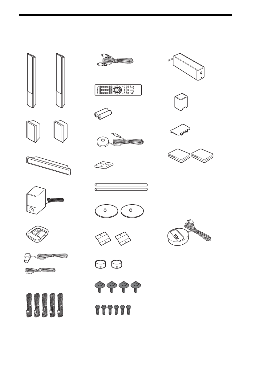
Unpacking
BDV-T20W
• Front speakers (2)
• Video cord (1)
• Remote commander
(remote) (1)
• R6 (size AA) batteries (2)
• Surround amplifier (1)
• Speaker cord cover (1)
• Surround speakers (2)
• Center speaker (1)
• Subwoofer (1)
• AM loop antenna (aerial) (1)
• FM wire antenna (aerial) (1)
or
• Speaker cords (5, white/red/
blue/gray/green)
• Calibration mic (1)
• Foot pads (1 set)
• Posts (2)
• Bases (2)
• Mounting plates (2)
• Post covers (2)
• Screws (large, with washer) (4)
• Speaker cord holder (1)
• Wireless transceivers (2)
• Operating Instructions
• Speaker Installation Guide
• Quick Setup Guide
• To stabilize S-AIR reception
• Setup Disc (DVD)
• DIGITAL MEDIA PORT
adapter (TDM-iP20) (1)
• Operating Instructions for
the DIGITAL MEDIA
PORT adapter (TDM-iP20)
• Screws (small) (6)
US
7
Page 8
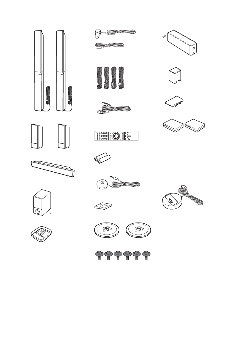
BDV-E500W
• Front speakers (2)
• FM wire antenna (aerial) (1)
or
• Speaker cords (4, blue/gray/
green/purple)
• Surround amplifier (1)
• Speaker cord cover (1)
• Surround speakers (2)
• Center speaker (1)
• Subwoofer (1)
• AM loop antenna (aerial) (1)
•Video cord (1)
• Remote commander
(remote) (1)
• R6 (size AA) batteries (2)
• Calibration mic (1)
• Foot pads (1 set)
• Bases (2)
• Screws (with washer) (6)
• Speaker cord holder (1)
• Wireless transceivers (2)
• Operating Instructions
• Speaker Installation Guide
• Quick Setup Guide
• To stabilize S-AIR reception
• Setup Disc (DVD)
• DIGITAL MEDIA PORT
adapter (TDM-iP20) (1)
• Operating Instructions for
the DIGITAL MEDIA
PORT adapter (TDM-iP20)
US
8
Page 9
Using the remote
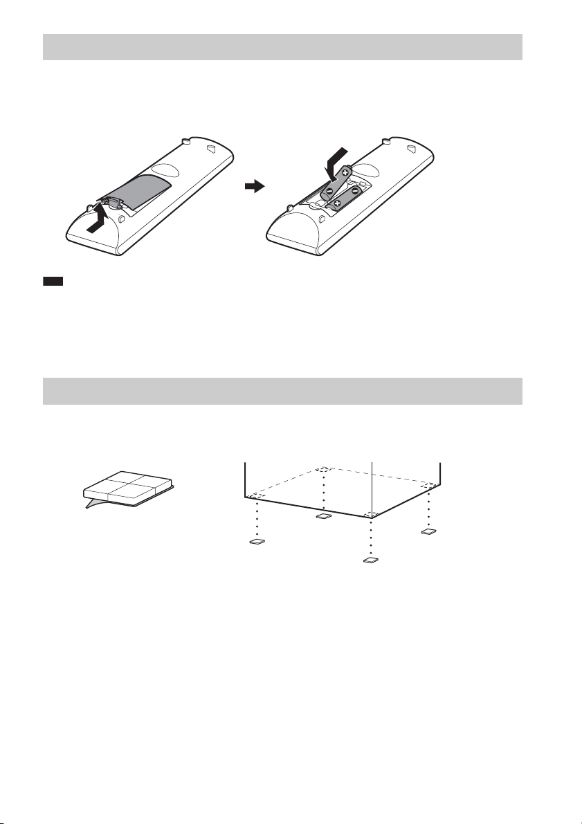
Inserting batteries into the remote
Insert two R6 (size AA) batteries (supplied) by matching the 3 and # ends on the batteries to the
markings inside the compartment.
Note
• Do not leave the remote in an extremely hot or humid place.
• Do not use a new battery with an old one.
• Do not drop any foreign object into the remote casing, particularly when replacing the batteries.
• If you do not intend to use the remote for an extended period of time, remove the batteries to avoid possible damage
from battery leakage and corrosion.
Attaching the foot pads to the subwoofer
Attach the foot pads (supplied) to the bottom of the subwoofer to stabilize the subwoofer and prevent
it from slipping.
Remove the foot pads from
the protective cover.
,
US
9
Page 10
Index to Parts and Control
A THEATER (page 68)
Switches to the optimum video mode for
watching movies automatically.
ONE-TOUCH PLAY (pages 41, 68)
For more information, refer to the pages
indicated in parentheses.
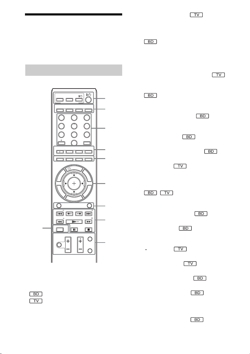
Remote control
ONE-TOUCH
THEATER
S-AIR
MODE
FAVORITES
AUDIO
U
G
FUNCTION
PRESET PRESET
TUNING
SCENE SEARCH
0
MUTING
Number 5, FAVORITES/AUDIO, CH +, and
N buttons have a tactile dot. Use the tactile dot
as a reference when operating the remote.
• : For system operations
• : For TV operations
(For details, see “Controlling Your TV with
the Supplied Remote” (page 73).)
TV
PLAY
BRAVIA Sync
DYNAMIC
BASS
NIGHT
CLEAR TIME
0
CC
WIDE
SUBTITLE
ANGLE
D.TUNING
RED
GREEN
BLUE
S
P
I
L
D
A
U
N
E
H
O
REPLAY ADVANCE
VOLUME
E
M
Y
SOUND MODE
CH
E
D
I
M
P
O
T
R
E
T
U
R
N
TV
321
654
987
ENTER
SYSTEM
MENU
YELLOW
P
O
P
U
P
/
M
P
O
TUNING
TV INPUT
DISPLAY
1
2
3
4
5
E
N
U
6
S
N
O
I
S
T
L
O
O
T
7
8
9
By only pressing the button, the TV turns
on, the TV is set for BD/DVD input
selector, and the system starts playing a disc
automatically.
TV "/1 (on/standby) (page 73)
Turns on the TV or sets it to standby mode.
"/1 (on/standby) (pages 31, 34, 41, 56)
Turns on the system or sets it to standby
mode.
B S-AIR MODE (page 62)
Selects playback mode for the S-AIR
receiver.
NIGHT (page 55)
Activates the night mode function.
DYNAMIC BASS (page 54)
Reinforces bass frequencies.
TV (page 73)
Changes to the TV operation mode for the
remote.
C Number buttons (pages 41, 57, 73)
Enters the title/chapter numbers, radio
frequencies, etc.
CLEAR (pages 45, 58)
Clears the entry field.
TIME (page 46)
Displays the elapsed/remaining playback
time in the front panel display.
(page 73)
Inputs “.” (dot) when inputting numerics.
ENTER (page 73)
Enters the selected item.
D AUDIO (pages 53, 54)
Selects the audio format/track.
SUBTITLE (page 43)
Selects the subtitle language when multilingual subtitles are recorded on a BDROM/DVD VIDEO.
D.TUNING (page 58)
Selects the radio frequencies.
10
US
Page 11
ANGLE (page 43)
Switches to other viewing angles when
multi-angles are recorded on a BD-ROM/
DVD VIDEO.
SYSTEM MENU (pages 38, 47, 54, 58,
61, 75, 75)
Enters the system menu.
FAVORITES (page 73)
Displays the favorite channel list.
CC (page 73)
Displays closed captioning (when
available).
WIDE (page 73)
Changes the aspect ratio of the connected
TV.
E Color buttons (RED/GREEN/BLUE/
YELLOW) (page 88)
Short cut keys for selecting items on some
BD’s menus (can also be used for BD’s
Java interactive operations).
F TOP MENU (page 44)
Opens or closes the BD’s or DVD’s Top
Menu.
DISPLAY (page 46)
Displays the playback information on the
TV screen.
POP UP/MENU (page 44)
Opens or closes the BD-ROM’s Pop-up
Menu, or the DVD’s menu.
OPTIONS (pages 41, 49, 50, 56)
Displays the options menu on the TV
screen.
HOME (pages 34, 41, 49, 50, 56, 70, 78)
Enters or exits the system’s home menu.
RETURN (pages 73, 88)
Returns to the previous display.
C/X/x/c
Moves the highlight to a displayed item.
(ENTER)
Enters the selected item.
GUIDE (page 73)
Displays the Digital Electronic Programme
Guide (EPG).
TOOLS (page 73)
Displays the operation menu for the current
display.
G FUNCTION (pages 37, 41, 49, 50, 56, 60)
Selects the playback source.
SOUND MODE (page 52)
Selects the sound mode.
H Playback operation buttons
See “Playback” (page 41).
./> (previous/next)
REPLAY/ADVANCE
m/M (fast reverse/fast forward)
N (play)
X (pause)
x (stop)
Radio operation buttons
See “Tuner” (page 56).
PRESET +/–
TUNING +/–
I MUTING (pages 41, 49, 73)
Turns off the sound temporarily.
VOLUME +/– (pages 41, 73)
Adjusts the volume.
CH +/– (page 73)
Selects the channels up and down.
TV INPUT (page 73)
Switches the TV’s input source between the
TV and other input sources.
DISPLAY (page 56)
Changes the radio information in the front
panel display between radio frequency and
station name.
J SCENE SEARCH (page 45)
Switches to Scene Search mode that lets
you move quickly between scenes within
the title currently being played back.
11
US
Page 12
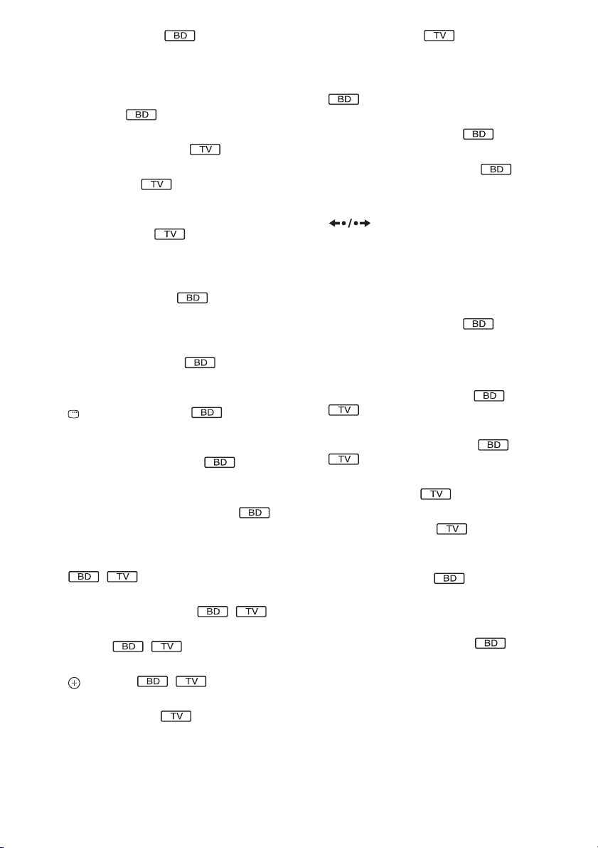
Front panel
FUNCTION
VOLUME
A "/1 (on/standby) (page 41)
Turns on the unit, or sets to standby mode.
B Play operation buttons (page 41)
N (play)
Starts or re-starts playback.
Plays a slideshow when a disc containing
JPEG image files is inserted.
x (stop)
Stops playback and remembers the stop
point (resume point).
The resume point for a title/track is the last
point you played or the last photo for a
photo folder.
FUNCTION
Selects the playback source.
VOLUME +/–
Adjusts the system’s volume.
Z (open/close)
Opens or closes the disc tray.
C S-AIR indicator
Lights up when the S-AIR transceiver is
inserted in the unit and the system transmits
sound.
D VIRTUAL 7.1CH indicator (page 38)
Lights up while virtual 7.1ch decoding is
activated.
E Power indicator
Lights up while the system is turned on.
F Front panel display
G Disc tray (page 41)
H (remote sensor)
12
US
Page 13
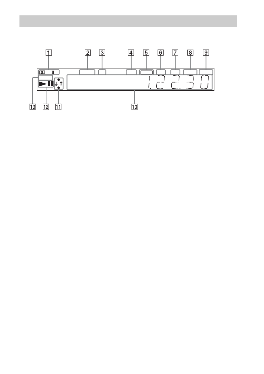
Front panel display
About the indications in the front panel display
PL
SLEEP
A Current surround format
B Lights up when a station is received.
(Radio only) (page 56)
C Lights up when stereo sound is
received. (Radio only) (page 56)
D Lights up when the external memory is
recognized. (page 29)
E Lights up when the HDMI OUT jack is
correctly connected to an HDCP (Highbandwidth Digital Content Protection)compliant device with HDMI or DVI
(Digital Visual Interface) input.
F Lights up when outputting 720p/1080i/
1080p video signals from the HDMI
OUT jack or 720p/1080i video signals
from the COMPONENT VIDEO OUT
jacks.
NEO:6 TUNED ST EXT HD NIGHT BASS
x
HDMI
G Lights up when outputting 1920 ×
1080p/24 Hz video signals.
H Lights up when the night mode is on.
(page 55)
I Lights up when the DYNAMIC BASS
function is on. (page 54)
J Displays system’s status such as
chapter, title, or track number, time
information, radio frequency, playing
status, decoding mode, etc.
K Lights up when the system is
accessing the network.
L Displays system’s playing status.
M Flashes when the sleep timer is set.
(page 75)
24P
13
US
Page 14
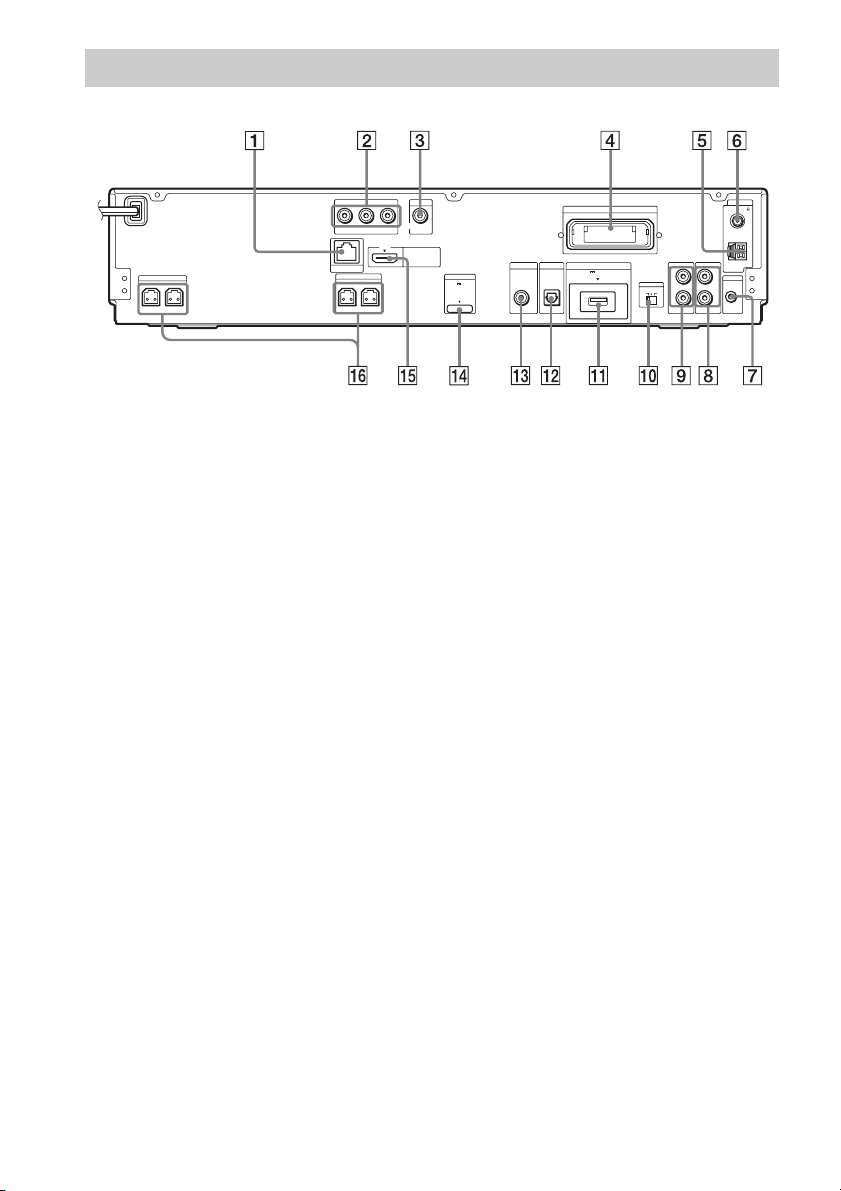
Rear panel
COMPONENT VIDEO OUT
Y
PB / CBPR / C
R
LAN(100)
FRONT R
SPEAKER
FRONT L
SPEAKER
CENTER SUBWOOFER
A LAN (100) terminal (page 30)
B COMPONENT VIDEO OUT jacks (page
24)
C VIDEO OUT jack (page 24)
D EZW-RT10 slot (page 28)
E AM terminal (page 27)
F COAXIAL 75Ω FM jack (page 27)
G A.CAL MIC jack (pages 34, 70)
H AUDIO (AUDIO IN L/R) jacks (page 26)
I TV (AUDIO IN L/R) jacks (page 25)
VIDEO OUT
HDMI OUT
DMPORT
DC5V
700mA MAX
SAT/CABLE
DIGITAL IN
COAXIAL
DIGITAL IN
OPTICAL
EZW-RT10
TV
EXT
DC5V
500mA MAX
S-AIR ID
ABC
TV
L
R
AUDIO IN AUDIO IN
J S-AIR ID switch (pages 32, 61)
K EXT slot (page 29)
L TV (DIGITAL IN OPTICAL) jack (page
25)
M SAT/CABLE (DIGITAL IN COAXIAL)
jack (page 26)
N DMPORT (DIGITAL MEDIA PORT) jack
(page 26)
O HDMI OUT jack (page 24)
P SPEAKER jacks (page 22)
ANTENNA
COAXIAL 75
FM
AM
AUDIO
L
A. CAL MIC
ECM-AC2
R
14
US
Page 15
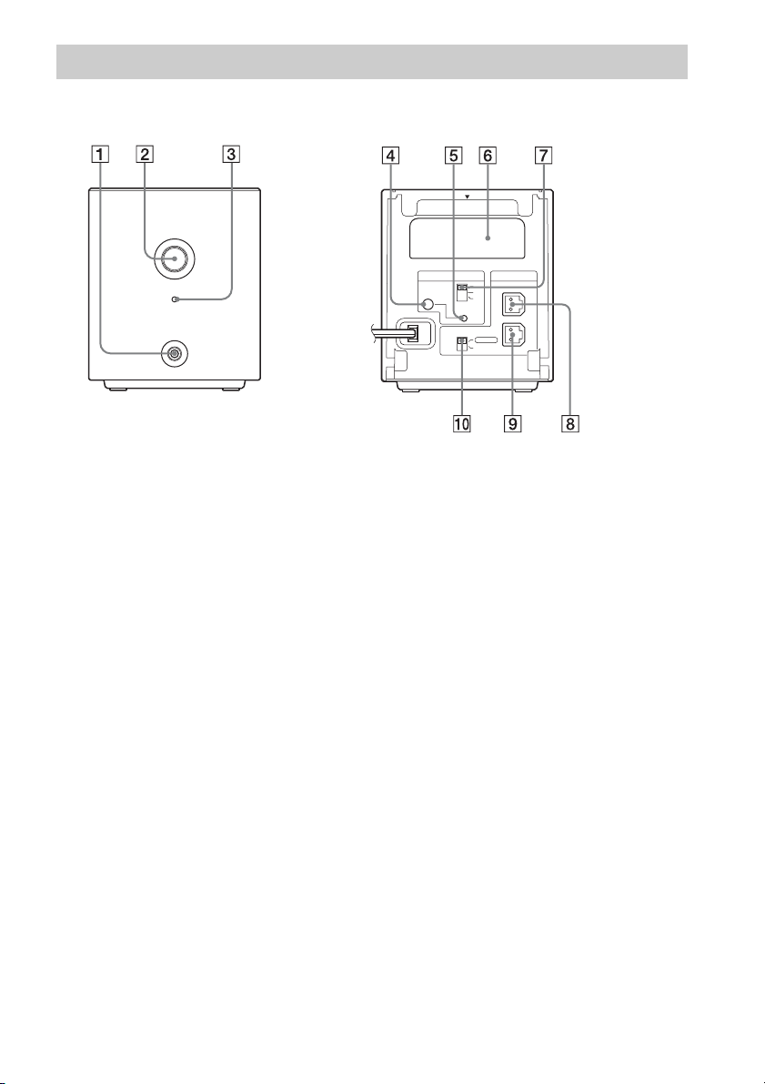
Surround amplifier
Front panel
POWER
POWER/ON LINE
PHONES
A PHONES jack (page 32)
B POWER (ON/OFF) (pages 32, 61)
C POWER / ON LINE indicator (pages 32,
61)
D PAIRING indicator (page 64)
E PAIRING (page 64)
Rear panel
EZW-RT10
S-AIR ID
SURROUND SELECTOR
PAI RI N G
A
B
C
SURROUND
SURROUND
SPEAKER
L
R
BACK
F Wireless transceiver (EZW-RT10) slot
(page 28)
G S-AIR ID switch (pages 32, 61)
H SPEAKER L jack (page 22)
I SPEAKER R jack (page 22)
J SURROUND SELECTOR switch (pages
32, 61)
15
US
Page 16
Getting Started
Step 1: Installing the System
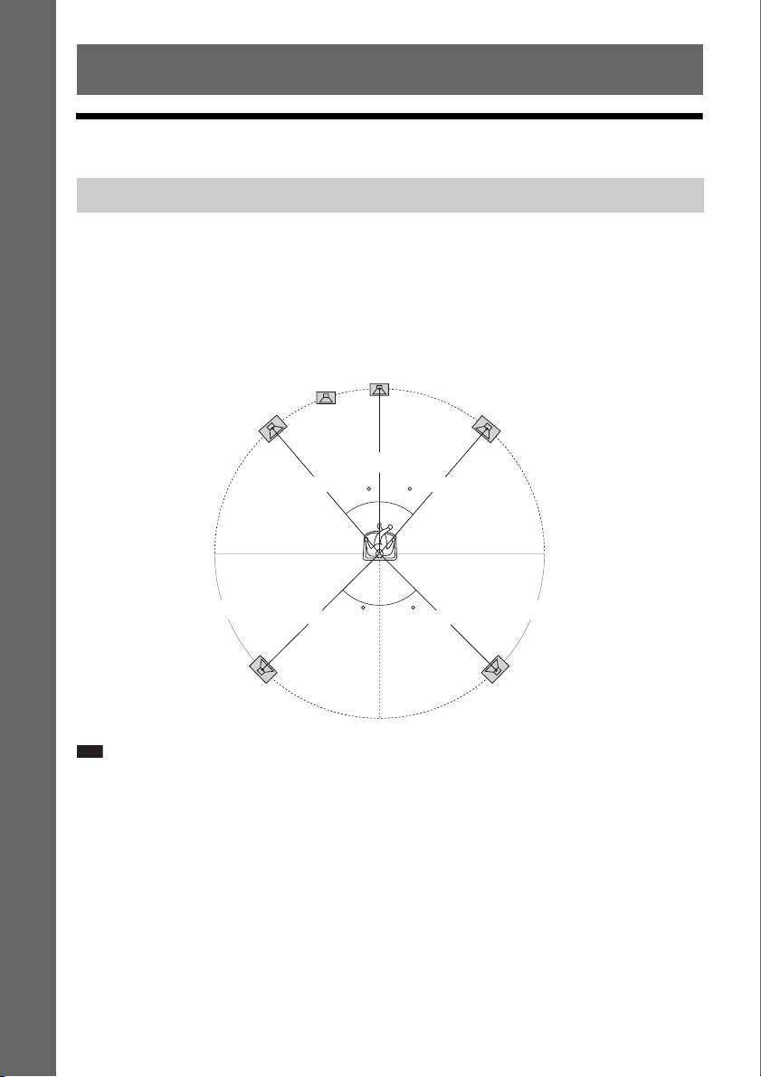
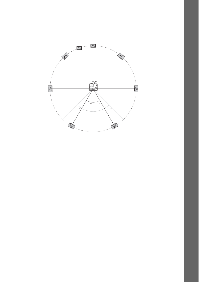
Positioning the speakers
Getting Started
For the best possible surround sound, place all speakers at the same distance from the listening position
(A). The distance can be between 0 to 23 feet (0.0 to 7.0 meters).
If you cannot place the center speaker and surround speakers at the same distance as (A), place them
within 23 feet (7.0 meters) of the listening position.
Place the surround speakers to the rear of the listening position (B).
The subwoofer can be placed anywhere in the room.
Subwoofer
Center speaker
Front left speaker (L)
Front right speaker (R)
A
A
30 30
B B
Surround left speaker (L)
Note
• Use caution when placing the speakers and/or speaker stands attached to the speakers on a specially treated (waxed,
oiled, polished, etc.) floor, as staining or discoloration may result.
• Do not lean or hang on a speaker, as it may fall down.
45
A
45
AA
Surround right speaker (R)
16
US
Page 17
To add the optional surround back speakers
You can enjoy 7.1 surround sound by purchasing the Wireless Surround Speaker Kit (WAHT-SBP1,
optional). The optional product lineup differs depending on the area.
For the position of the surround back speakers, refer the illustration below (C).
Subwoofer
Center speaker
Getting Started
Front left speaker (L)
Surround left
speaker (L)
Surround back left speaker (L)
(optional)
Front right speaker (R)
Surround right
speaker (R)
30 30
45 45
CC
Surround back right speaker (R)
(optional)
17
US
Page 18
Installing the speakers on a wall
Caution
• Contact a screw shop or installer regarding the wall material or screws to be used.
• Use screws that are suitable for the wall material and strength. As a plaster board wall is especially fragile, attach
the screws securely to a beam and fasten them to the wall. Install the speakers on a vertical and flat wall where
reinforcement is applied.
• Sony is not responsible for accidents or damage caused by improper installation, insufficient wall strength or
Getting Started
improper screw installation, natural calamity, etc.
Before installing the front speakers of BDV-E500W on a wall, you need to disassemble the speakers.
You can install the upper part of a speaker on a wall.
To disassemble the speaker
(Front speakers of BDV-E500W only)
1 Disconnect the speaker cords from the speaker.
Rear of the speaker
2 Remove the screw (pre-installed) at the rear of the speaker.
This screw is used when reassembling the speaker. Be sure not to lose the screw.
18
Screw
US
Rear of the speaker
Page 19
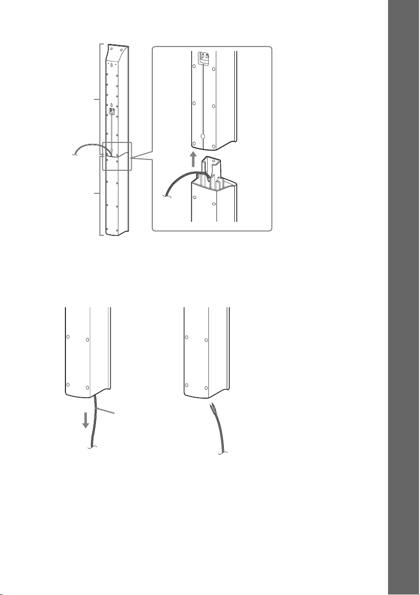
3 Disassemble the speaker by lifting the upper part of the speaker.
Upper part
Lower part
Rear of the speaker
4 Pull out the speaker cord from the bottom of the lower part of the speaker.
The removed speaker cord is used when installing the speaker on a wall.
Lower part of the speaker
Getting Started
,
Speaker cord
19
US
Page 20
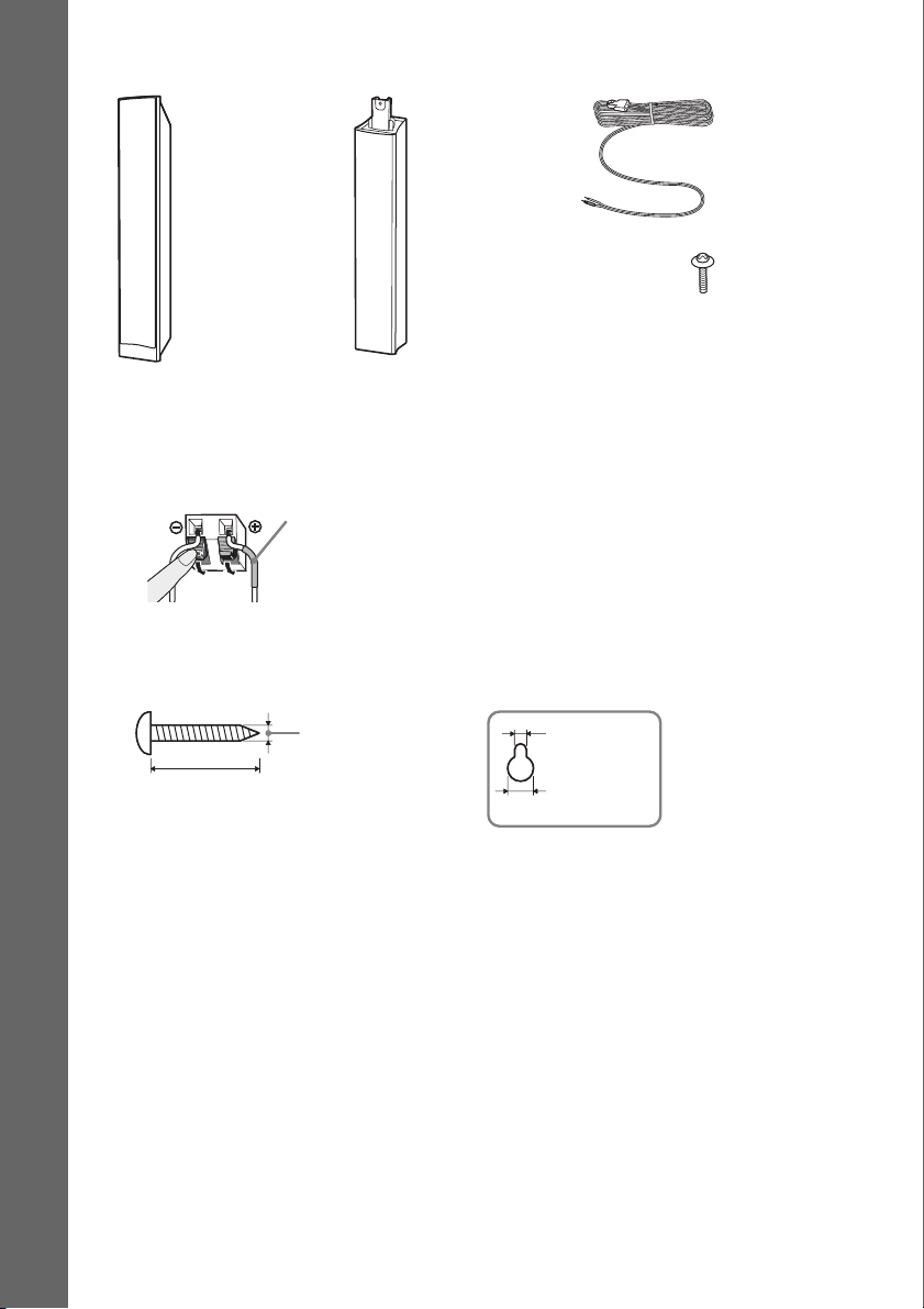
Fully-disassembled illustration
Getting Started
Upper part of
the speaker
Lower part of
the speaker
Speaker cord
Screw
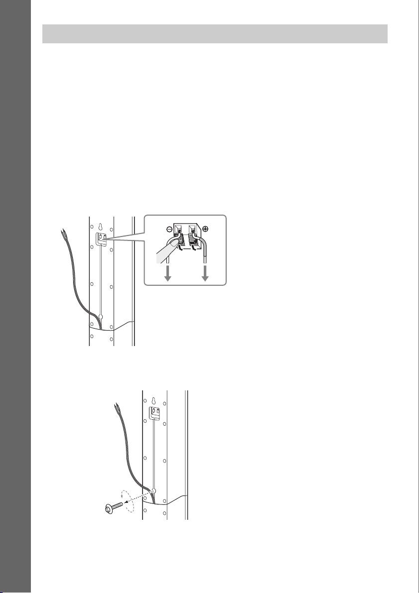
To install the speakers on a wall
Before installing the speakers on a wall, connect the speaker cord to the speaker.
Be sure to match the speaker cords to the appropriate terminals on the speakers: the speaker cord with
the color tube to 3, and the speaker cord without the color tube to #.
Color tube
Front left speaker (L): White
Front right speaker (R): Red
Center speaker: Green
Surround left speaker (L): Blue
Surround right speaker (R): Gray
1 Prepare screws (not supplied) that are suitable for the hole on the back of each speaker.
See the illustrations below.
Hole on the back of
the speaker
30 mm (1 3/16 inches)
4 mm (
5
/32 inch)
5 mm
(7/32 inch)
10 mm
13
/32 inch)
(
20
US
Page 21
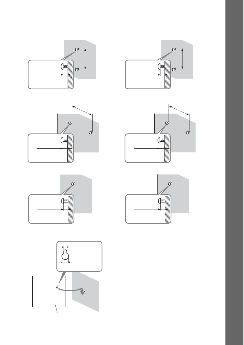
2 Fasten the screws to the wall.
BDV-T20W
For the front speakers
8 to 10 mm
11
/32 to 13/32
(
For the center speaker
11
/32 to 13/32
(
For the surround speakers
inch
8 to 10 mm
inch
)
)
217 mm
8
5/8
(
160 mm
6
3/8 inches)
(
inches
BDV-E500W
For the front speakers
)
8 to 10 mm
11
/32 to 13/32
(
For the center speaker
8 to 10 mm
11
(
/32 to 13/32
For the surround speakers
inch
inch
Getting Started
210 mm
(
8
3/8
inches
)
)
219 mm
(
8
5/8 inches)
)
8 to 10 mm
11
/32 to 13/32
(
inch
)
3 Hang the speakers on the screws.
5 mm
7
/32 inch)
(
10 mm
13
/32 inch)
(
Rear of the speaker
11
(
Hole on the back of
the speaker
8 to 10 mm
/32 to 13/32
inch
)
US
21
Page 22

Step 2: Connecting the System
For connecting the system, read the information on the following pages.
Do not connect the AC power cord (mains lead) of the unit to a wall outlet (mains) until all the other
connections are made.
Note
• When you connect another component with a volume control, turn down the volume of the other components to a
Getting Started
level where sound is not distorted.
Connecting the speakers
The connector of the speaker cords and the color tube are color-coded depending on the type of speaker.
Connect the speaker cords to match the color of the SPEAKER jacks of the unit.
Be sure to match the speaker cords to the appropriate terminals on the speakers: the speaker cord with
the color tube to 3, and the speaker cord without the color tube to #. Do not catch the speaker cord
insulation (rubber covering) in the speaker terminals.
22
US
Page 23
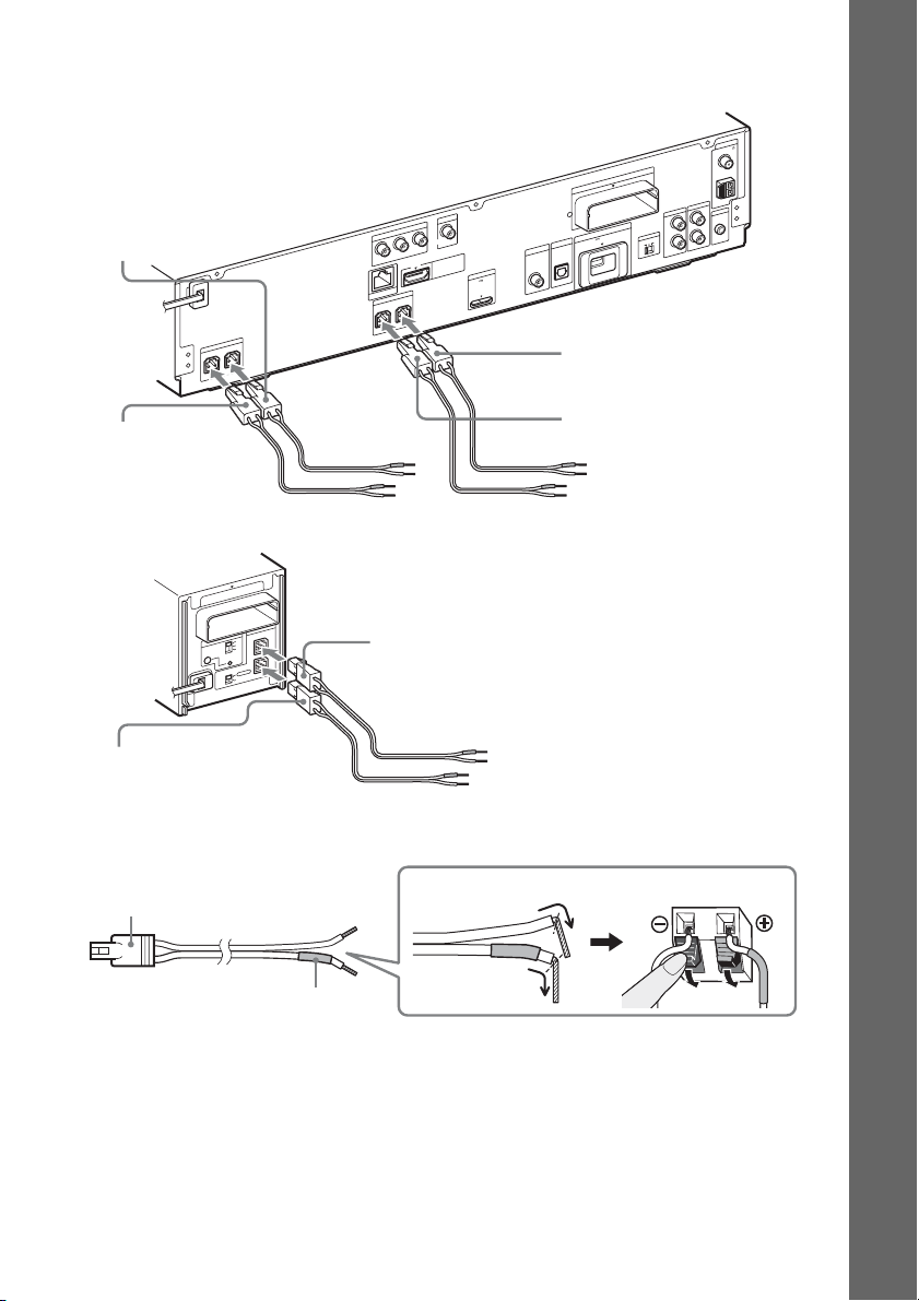
To connect speaker cords to the unit
When connecting to the unit, insert the connector until it clicks.
Rear panel of the unit
T
U
O
O
E
ID
V
T
Purple
(Subwoofer)
R
E
K
A
E
P
S
R
E
F
O
O
W
B
U
S
R
E
T
N
E
C
Green
(Center speaker)
Rear panel of the surround amplifier
10
T
-R
W
Z
E
R
E
K
A
E
P
S
ID
IR
A
-A
S
L
B
C
RING
PAI
R
R
O
T
C
E
L
E
S
D
D
N
N
U
U
O
R
O
R
R
U
S
R
U
D
S
N
U
O
R
R
U
S
K
C
A
B
U
O
O
E
ID
V
T
N
E
N
O
P
M
O
C
R
C
/
R
P
B
C
/
B
P
LAN(100)
Y
P
S
R
T
N
O
R
F
T
U
I O
M
D
H
T
R
PO
M
D
X
DC5V
A
M
A
m
0
0
R
E
K
A
E
N
O
R
F
7
L
T
Blue
(Surround left speaker (L))
10
T
-R
W
Z
E
T
EX
X
A
M
A
m
0
0
5
DC5V
V
T
IN
E
L
L
B
A
A
IT
/C
IG
T
D
A
S
IN
L
A
IT
IG
D
L
A
IC
T
P
O
L
IA
X
A
O
C
White
(Front left speaker (L))
Red
(Front right speaker (R))
Getting Started
A
N
N
E
T
N
A
5
7
L
A
I
X
A
O
C
M
F
M
A
O
I
D
U
A
IC
M
L
V
A
L
T
. C
A
2
C
-A
M
C
E
L
R
S-AIR ID
C
B
R
A
IN
IO
D
U
A
IN
O
I
D
U
A
Gray
(Surround right speaker (R))
To connect speaker cords to the speaker
Connector
Color tube
(–)
(+)
Rear of the speaker
23
US
Page 24
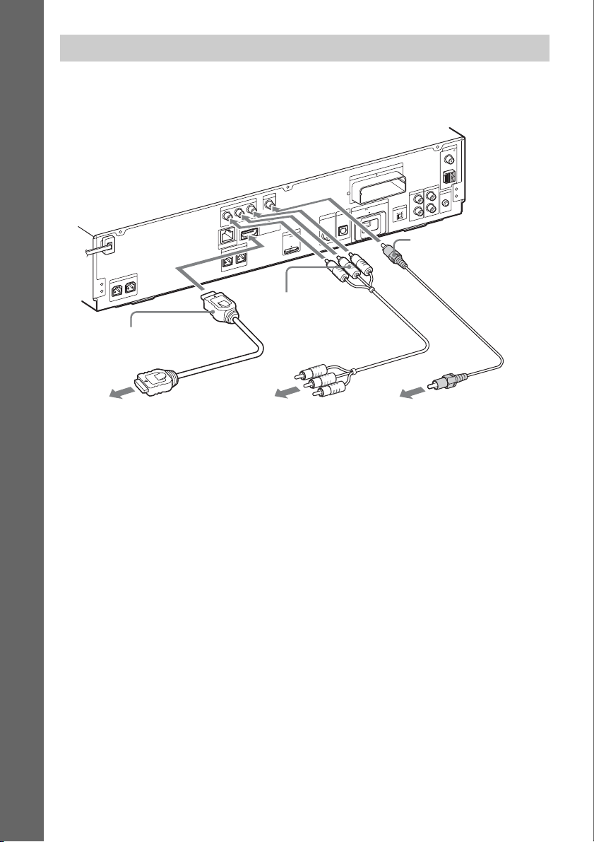
Connecting the TV (Video connection)
This connection sends a video signal to the TV.
Depending on the jacks on your TV, select the connection method.
Rear panel of the unit
Getting Started
T
U
O
O
E
ID
V
T
U
O
O
E
ID
V
T
N
E
N
O
P
M
O
C
R
/ C
R
P
B
C
/
B
P
R
E
K
A
E
P
S
R
E
F
O
O
W
B
U
S
R
E
T
N
E
C
B HDMI cable (not supplied)
LAN(100)
Y
S
T
N
O
R
F
UT
I O
DM
H
R
E
K
A
E
P
L
T
N
O
R
F
R
C Component video
cable (not supplied)
T
OR
P
M
D
X
DC5V
A
M
A
m
0
0
7
A
N
N
E
T
N
A
5
7
L
A
I
X
A
O
C
M
0
1
T
-R
W
Z
E
XT
E
X
A
M
A
m
0
S-AIR
0
5
DC5V
V
T
IN
E
L
L
B
A
A
IT
/C
IG
T
D
A
S
IN
L
A
IT
IG
D
L
A
IC
T
P
O
L
A
I
X
A
O
C
A
F
M
A
O
I
D
U
A
IC
M
L
V
A
L
T
. C
A
2
C
-A
M
C
E
L
R
ID
C
B
R
IN
O
I
D
U
A
N
I
O
I
D
U
A
A Video cord (supplied)
To the HDMI IN jack
of the TV.
To the component video
input jacks of the TV.
To the video input jack of
the TV.
Method 1: Video cord (A) connection
This is the basic connection.
Method 2: HDMI* cable (B) and video cord (A) connection
If your TV has an HDMI jack, connect to the TV both with an HDMI cable and video cord. Picture
quality will be improved compared to using only the video cord connection.
When connecting with the HDMI cable, you need to select the type of output signal (pages 34, 81).
To view images from the DIGITAL MEDIA PORT adapter, you need to connect to the TV with the
video cord. Video signals from the DIGITAL MEDIA PORT adapter are not output via the HDMI OUT
jack.
* HDMI (High-Definition Multimedia Interface)
Method 3: Component video cable (C) and video cord (A) connection
If your TV does not have an HDMI jack, but has component video input jacks, connect to the TV both
with a component video cable and video cord. Picture quality will be improved compared to using only
the video cord connection.
When connecting with the component video cable, you need to select the type of output signal (pages
34, 81).
To view images from the DIGITAL MEDIA PORT adapter, you need to connect to the TV with the
video cord. Video signals from the DIGITAL MEDIA PORT adapter are not output via the
COMPONENT VIDEO OUT jack.
US
24
Page 25
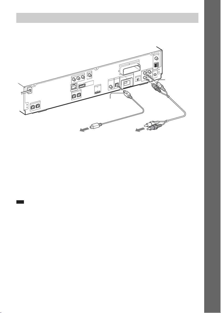
Connecting the TV (Audio connection)
This connection sends an audio signal to the unit from the TV. To listen to TV sound via the system,
perform this connection.
Rear panel of the unit
A
N
N
E
T
N
A
5
7
L
A
I
X
A
O
C
M
0
1
T
-R
W
Z
E
T
U
O
O
E
ID
V
T
U
O
O
E
ID
V
T
N
E
N
O
P
M
O
C
R
C
/
R
P
B
C
/
B
P
Y
LAN(100)
P
S
R
T
N
O
R
R
E
K
A
E
P
S
R
E
F
O
O
W
B
U
S
R
E
T
N
E
C
F
T
U
I O
M
D
H
R
E
K
A
E
L
T
N
O
R
F
E Digital optical cord
(not supplied)
DC5V
0
7
A
/C
T
A
S
A
IT
IG
D
T
R
PO
DM
X
A
M
A
m
0
A
I
X
A
O
C
T
EX
X
A
M
A
m
0
S-AIR ID
0
5
DC5V
V
T
IN
E
L
L
B
A
IT
IG
D
IN
L
L
A
IC
T
P
O
L
AB
F
M
A
O
I
D
U
A
IC
M
L
V
A
L
T
. C
A
2
C
-A
M
C
E
L
R
C
R
IN
IO
D
U
A
IN
IO
D
U
A
D Audio cord
(not supplied)
Getting Started
To the digital optical out jack
To the audio out jacks of the TV.
of the TV.
Method 1: Audio cord (D) connection
This is the basic connection and sends an analog audio signal.
Method 2: Digital optical cord (E) connection
When the TV has a digital optical output jack, you can improve sound quality by connecting with a
digital optical cord in addition to an audio cord connection.
With a digital audio connection, the system receives a Dolby Digital multiplex broadcast signal and
you can enjoy multiplex broadcast sound.
Note
• The system c an accept both digital and analog signals. Digital signals have priority over analog signals. If the digital
signal ceases, the analog signal will be processed after 2 seconds.
25
US
Page 26
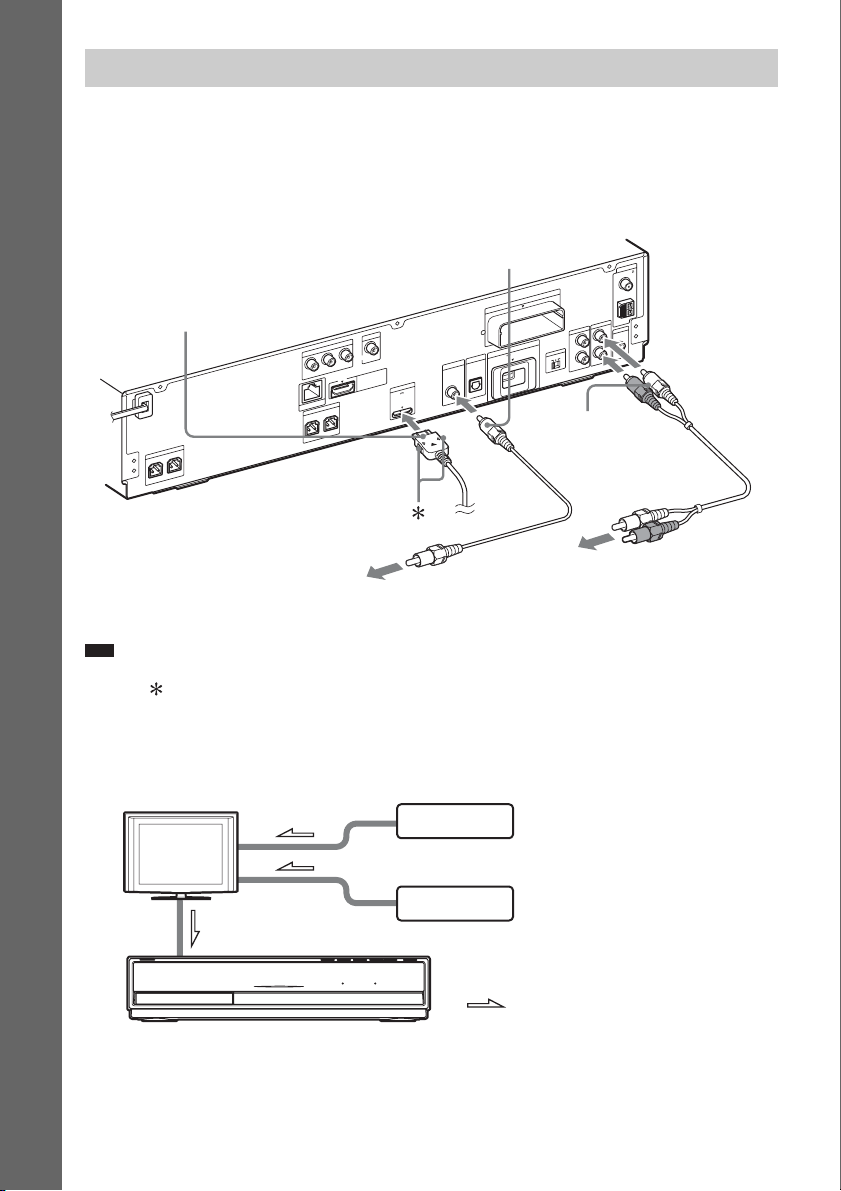
Connecting the other components
You can enjoy connected components via the system’s speakers.
• DIGITAL MEDIA PORT adapter: F (TDM-iP20 is supplied. You can also use other DIGITAL
MEDIA PORT adapters.)
• VCR, digital satellite receiver, PlayStation, or portable audio source, etc. (not supplied): G
• VCR or digital satellite receiver, etc. (not supplied) which has a digital coaxial output jack: H
Getting Started
Rear panel of the unit
F DIGITAL MEDIA PORT
adapter (page 60)
O
O
E
ID
V
T
N
E
N
O
P
M
O
C
P
B
C
/
B
P
Y
R
LAN(100)
E
K
A
E
P
S
L
T
N
O
R
F
R
T
N
O
R
R
E
K
A
E
P
S
R
E
F
O
O
W
B
U
S
R
E
T
N
E
C
F
To the digital coaxial out jack of the
VCR or digital satellite receiver, etc.
Note
• Connect the DIGITAL MEDIA PORT adapter so that the V marks are aligned. When disconnecting, pull out while
pressing .
H Digital coaxial cord (not
supplied)
T
U
O
O
E
ID
V
T
U
R
/ C
R
UT
I O
M
D
H
T
R
PO
DM
X
DC5V
A
M
A
m
0
0
7
A
N
N
E
T
N
A
5
7
L
A
I
X
A
O
C
M
0
1
T
-R
W
Z
E
T
X
E
X
A
M
A
m
0
S-AIR ID
0
5
DC5V
V
T
IN
E
L
L
B
A
A
IT
/C
IG
T
D
A
S
IN
L
A
IT
IG
D
L
A
IC
T
P
O
L
A
I
X
A
O
C
A
F
M
A
O
I
D
U
A
IC
M
L
V
A
L
T
. C
A
2
C
-A
M
C
E
L
R
C
B
R
IN
IO
D
U
A
IN
IO
D
U
A
G Audio cord (not
supplied)
To the audio out jacks of the
VCR, digital satellite receiver,
PlayStation, or portable audio
source, etc.
If your TV has multiple audio/video inputs
You can enjoy sound with the speakers of the system through the connected TV. Connect the
components as follows.
TV
System
VCR, digital satellite receiver,
PlayStation, etc.
VCR, digital satellite receiver,
PlayStation, etc.
:Signal flow
Select the component on the TV. For details, refer to the operating instructions of the TV.
If the TV does not have multiple audio/video inputs, a switcher will be necessary to receive sound from
more than one component.
US
26
Page 27
p
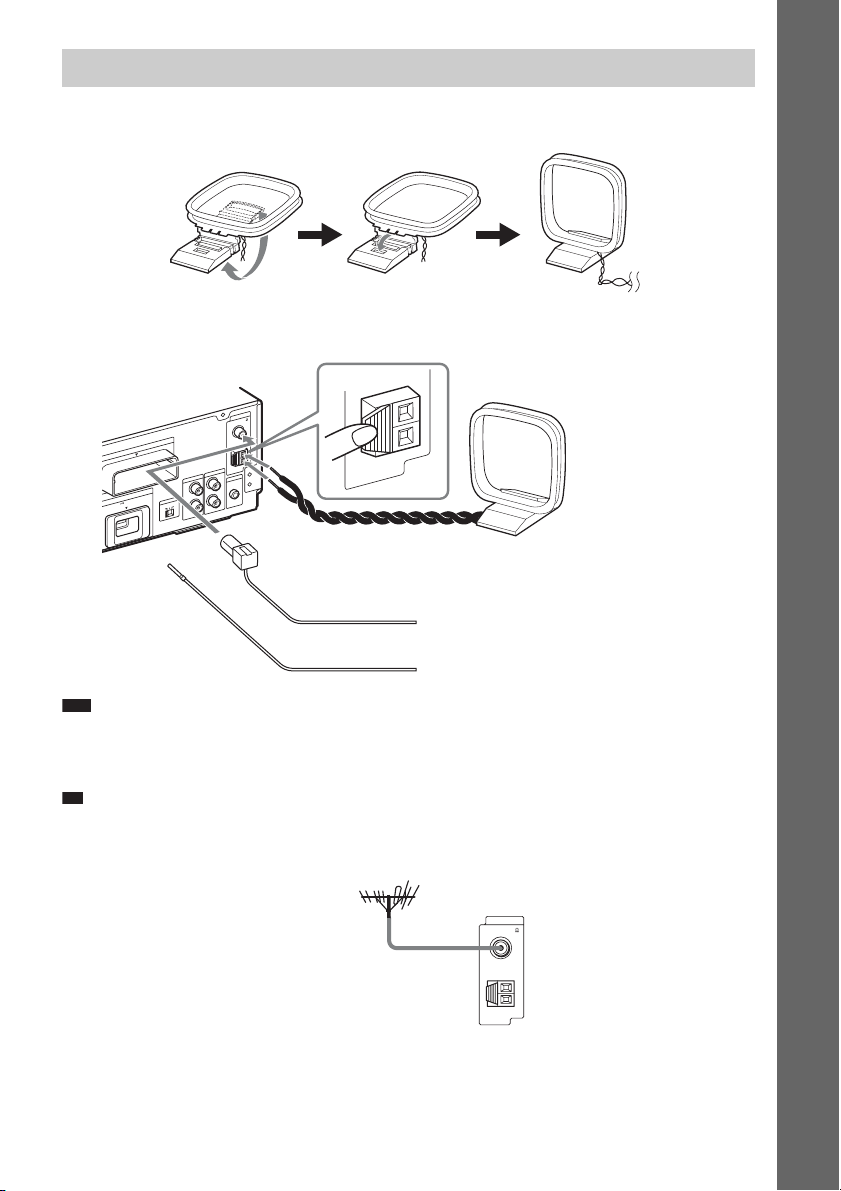
Connecting the antenna (aerial)
To assemble the AM loop antenna (aerial)
To connect the antenna (aerial)
Rear panel of the unit
A
N
N
E
T
N
A
5
7
L
A
I
X
A
O
C
M
0
1
T
-R
W
Z
E
T
X
E
X
A
M
A
m
0
S-AIR ID
0
5
DC5V
A
F
M
A
O
I
D
U
A
IC
M
L
V
A
L
T
. C
A
2
C
-A
M
C
E
L
R
C
B
R
N
I
IO
D
U
A
IN
O
I
D
U
A
AM
AM loop antenna (aerial)
or
(supplied)
FM wire antenna (aerial)
(supplied)
Getting Started
Note
• Keep the AM loop antenna (aerial) and cord away from the system or other AV components, as noise may result.
• Be sure to fully extend the FM wire antenna (aerial).
• After connecting the FM wire antenna (aerial), keep it as horizontal as possible.
Ti
• Adjust the direction of the AM loop antenna (aerial) for best AM broadcast sound.
• If you have poor FM reception, use a 75-ohm coaxial cable (not supplied) to connect the unit to an outdoor FM
antenna (aerial) as shown below.
Outdoor FM antenna (aerial)
Unit
ANTENNA
COAXIAL 75
FM
AM
27
US
Page 28
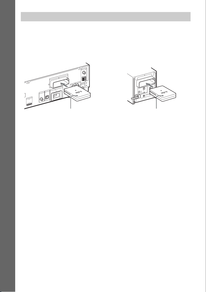
Inserting the wireless transceiver
You can transmit sound from the unit to an S-AIR product, such as the surround amplifier or S-AIR
receiver.
To transmit sound from the unit, you need to insert the wireless transceivers into the unit and S-AIR
product.
For details of S-AIR products, see “Using an S-AIR Product” (page 61).
Getting Started
Rear panel of the unit
DC5V
7
A
N
N
E
T
N
A
5
7
L
A
I
X
A
O
C
M
0
1
T
-R
W
Z
E
XT
E
X
A
M
A
m
0
S-AIR ID
0
5
DC5V
V
T
IN
E
L
L
B
A
A
IT
/C
IG
T
D
A
S
IN
L
A
IT
IG
D
T
R
PO
DM
X
A
M
A
m
0
0
L
A
IC
T
P
O
L
A
I
X
A
O
C
A
F
M
A
O
I
D
U
A
IC
M
L
V
A
L
T
. C
A
2
C
A
-
M
C
E
L
R
C
B
R
IN
O
I
D
U
A
N
I
O
I
D
U
A
Rear panel of the surround
amplifier
10
T
R
-
W
Z
E
R
E
K
A
E
P
S
ID
IR
A
-A
S
L
B
C
PAIRI N G
R
R
O
T
C
E
L
E
S
D
D
N
N
U
U
O
R
O
R
R
U
S
R
U
D
S
N
U
O
R
R
U
S
K
C
A
B
Wireless
transceiver
Wireless
transceiver
28
US
Page 29
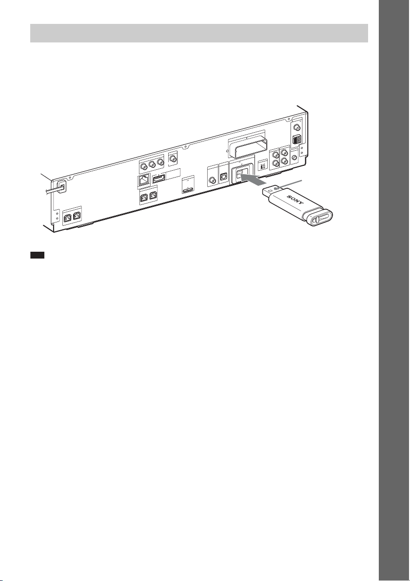
Inserting the external memory
Insert the external memory device (1 GB or larger USB flash memory, such as Sony USM2GL,
USM4GL, or USM1GH, not supplied) into the EXT slot. Check that “EXT” lights up in the front panel
display when turning the system on. By connecting an external memory, you can enjoy additional
contents (BonusView/BD-Live) depending on the disc (page 48).
A
N
N
E
T
N
Rear panel of the unit
0
1
T
-R
W
Z
E
T
U
O
O
E
ID
V
T
U
O
O
E
ID
V
T
N
E
N
O
P
M
O
C
R
/ C
R
P
B
C
/
B
P
Y
LAN(100)
S
T
N
O
R
R
E
K
A
E
P
S
R
E
F
O
O
W
B
U
S
R
E
T
N
E
C
F
T
U
I O
M
D
H
DC5V
R
E
K
A
E
P
N
O
R
F
R
7
L
T
A
/C
T
A
S
A
IT
IG
D
T
R
PO
DM
X
A
M
A
m
0
0
A
I
X
A
O
C
T
EX
X
A
M
A
m
0
S-AIR ID
0
5
DC5V
V
T
IN
E
L
L
B
A
IT
IG
D
IN
L
L
A
TIC
P
O
L
AB
Ex. Sony USM2GL (not supplied)
Note
• Insert the external memory into the EXT slot as far as it will go.
• Insert the external memory straight. If you force the external memory into the slot, this will cause damage to both
the external memory and the unit.
• Keep the external memory away from small children to prevent them from accidentally swallowing it.
• Do not apply too much pressure to the external memory in the slot, as it may cause a malfunction.
• To avoid data corruption or damage to the external memory, turn the system off when inserting or removing the
external memory.
• Do not insert an external memory that contains photo or music files to avoid corrupting the external memory data.
A
5
7
L
A
I
X
A
O
C
M
F
M
A
O
I
D
U
A
IC
M
L
V
A
L
T
. C
A
2
C
-A
M
C
E
L
R
C
R
IN
IO
D
U
A
N
I
IO
D
U
A
With the terminal
side up
Getting Started
To remove the external memory
1 Press "/1 to turn the system off.
2 Pull out the external memory from the EXT slot.
29
US
Page 30
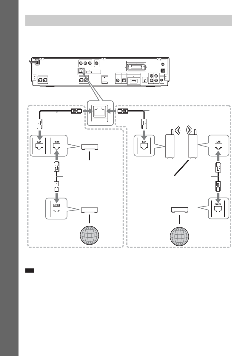
Connecting to the network
Connect the LAN (100) terminal of the unit to your Internet source using a network cable to update the
system’s software using the network. You can also enjoy BD-Live (page 48).
Make the appropriate settings in [Internet Settings] under [Network Settings] (page 88).
Rear panel of the unit
ANTENNA
COAXIAL75
FM
AM
AUDIO
L
A. CAL MIC
ECM-AC2
Getting Started
SPEAKER
CENTER SUBWOOFER
COMPONENT VIDEO OUT
Y
LAN(100)
SPEAKER
FRONT R
PB / CBPR / C
FRONT L
VIDEO OUT
R
HDMI OUT
DMPORT
DC5V
700mA MAX
SAT/CABLE
DIGITAL IN
COAXIAL
EZW-RT10
EXT
500mA MAX
ABC
TV
S-AIR ID
RLR
AUDIO IN AUDIO IN
TV
DIGITAL IN
DC5V
OPTICAL
When connecting to a
broadband router directly
Network cable
(not supplied)
Broadband router
(not supplied)
To PC
LAN(100)
When connecting via a wireless
LAN router
Network cable
(not supplied)
Ethernet/wireless
LAN media converter
Wireless LAN router
(access point)
(not supplied)
(not supplied)
Network cable
(not supplied)
ADSL modem/
Cable modem
(not supplied)
Internet
To PC
Network cable
(not supplied)
ADSL modem/
Cable modem
(not supplied)
Internet
To update the system’s software using the network
See [Network Update] (page 79) and [Software Update Notification] (page 87).
Note
• Do not connect a phone line to the LAN (100) terminal, as it may cause a malfunction.
• Do not connect the LAN terminal of the unit to the LAN terminal of the PC.
• Depending on the modem or router, the type of network (LAN) cable, straight or crossing, differs. For details on
the network (LAN) cables, refer to the operating instructions supplied with the modem or router.
• For optimal performance of BD-Live functions, we recommend using an Internet connection with an effective
speed of 1 Mbps or greater.
30
US
Page 31

Connecting the AC power cords (mains leads)
Before connecting the AC power cords (mains leads) of the unit and the surround amplifier to a wall
outlet (mains), connect the front, center speakers and subwoofer to the unit and surround speakers to
the surround amplifier.
Wall outlet (mains): The shape
of the wall outlet (mains) differs
depending on the area.
Getting Started
To turn off the demonstration mode
(Except for U.S. models)
After connecting the AC power cord (mains lead), the demonstration appears in the front panel display.
You can turn off the demonstration simply by pressing "/1 on the remote. For details, see “About the
demonstration” (page 76).
To turn the system on/off (standby mode)
"/1
321
654
987
Press "/1.
31
US
Page 32

Step 3: Setting up the Wireless System
To use the wireless system, you need to set up
the surround amplifier. Before setting, make
sure that the wireless transceivers are inserted
into the unit and the surround amplifier correctly
Getting Started
(page 28).
This wireless system is called “S-AIR.” For
details of the S-AIR function, see “Using an
S-AIR Product” (page 61).
COMPONENT VIDEO OUT
VIDEO OUT
Y
PB / CBPR / C
R
SPEAKER
CENTER SUBWOOFER
HDMI OUT
LAN(100)
SPEAKER
FRONT R
FRONT L
TV
SAT/CABLE
DIGITAL IN
DIGITAL IN
DC5V
DMPORT
DC5V
700mA MAX
COAXIAL
OPTICAL
3 Set the SURROUND SELECTOR switch
of the surround amplifier to
SURROUND.
4 Set the S-AIR ID switch of the surround
amplifier to A.
5 Press POWER on the surround
amplifier.
The POWER / ON LINE indicator turns
green. If it doesn’t, check the transmission
status as follows.
To check the transmission status
ANTENNA
COAXIAL75
EZW-RT10
FM
AM
AUDIO
TV
EXT
500mA MAX
L
A. CAL MIC
ECM-AC2
S-AIR ID
ABC
RLR
AUDIO IN AUDIO IN
You can check the status of sound transmission
between the unit and surround amplifier by
observing the POWER / ON LINE indicator of
the surround amplifier.
S-AIR ID switch
"/1
321
654
987
0
POWER / ON LINE
Indicator
POWER
POWER
POWER/ON LINE
PHONES
PHONES jack
S-AIR ID switch
EZW-RT
S-AIR ID
SURROUND SELECTOR
SURROUND
10
SPEAKER
A
B
C
L
PAIRING
R
SURROUND
SURROUND
BACK
SELECTOR switch
The unit transmits sound to the surround
amplifier that is connected to the surround
speakers. To establish sound transmission,
perform the following Steps.
1 Set the S-AIR ID switch of the unit to A.
2 Press "/1.
The system turns on.
POWER / ON LINE
Status
indicator
Turns green. Sound transmission is
established.
Flashes green. Sound transmission is not
established.
Turns red. The surround amplifier does
not output sound.
Turns off. The surround amplifier turns
off or its protection is active.
For details of the surround amplifier, see
“Surround amplifier operation” (page 99).
To enjoy sound by using
headphones
You can enjoy the system’s sound by connecting
the headphones to the PHONES jack on the
surround amplifier.
Note
• The volume of the unit may become minimum if you
turn off the surround amplifier while the headphones
are connected to the surround amplifier, or radio
reception is poor. In this case, “HP NO LINK” and
“VOLUME MIN” appear alternately in the front
panel display. Check radio reception, and set the
volume again.
• When you connect the headphones to the surround
amplifier, sound is not output from the system’s
speakers.
32
US
Page 33

When you use multiple S-AIR
products
See “Establishing sound transmission between
the unit and S-AIR sub unit (ID setting)”
(page 61).
To attach the cover to the
surround amplifier
After connecting and setting, you can attach the
cover to the surround amplifier for organizing
and storing excess speaker cords.
1 Attach the speaker cord cover by
sliding it down along the grooves at the
edges of the surround amplifier.
Speaker cord cover
Surround amplifier
Grooves
Push the speaker cord cover down until you
hear a click. Turn the surround amplifier
upside down, then store the cords in the
speaker cord cover.
2 Insert the tabs of the speaker cord
holder in the slots of the speaker cord
cover, and press it into place.
Speaker cord holder
Surround amplifier
m
Getting Started
33
US
Page 34

Step 4: Performing the Easy Setup
Follow the Steps below to make the basic
adjustments for using the system.
Displayed items vary depending on the country
model.
Getting Started
5 Press or c.
The setting message appears.
Easy Setup
Set the items below required to use this unit.
Each of these items may be changed later under "Setup."
- Select the TV connection method
- Select the TV type
- Select the BD Internet Connection
- Select the Standby Mode
- Execute the Auto Calibration
Check that all cables, etc. have been connected and then start.
Start
"/1
321
654
987
0
C/X/x/c,
HOME
1 Turn on the TV.
2 Press [/1 on the unit, and POWER on
the surround amplifier.
3 Switch the input selector on your TV so
that the signal from the system
appears on the TV screen.
The Easy Setup Display for OSD language
selection appears.
- OSD
Easy Setup
Select the language to be displayed by this unit.
English
Français
Español
Português
If the Easy Setup Display does not
appear
Recall the Easy Setup Display. See “To
recall the Easy Setup Display” (page 37).
4 Press X/x to select a language for the
OSD.
This message appears only when
performing the [Easy Setup] for the first
time. It does not appear when performing
the [Easy Setup] accessed via the [Setup]
setting.
6 Press or c.
The Setup Display for video cable selection
appears.
Easy Setup - TV Connection Method
Select the video cable connecting this unit and the TV.
Component Video
Video
7 Press X/x to select the cable used to
connect the unit and TV.
Check the connection of the unit and TV
(page 24).
• When you connect the unit and TV with
an HDMI cable, select [HDMI], go to
Step 8 and set the video output resolution
to match your TV.
• When you connect the unit and TV with a
component video cord, select
[Component Video], go to Step 8 and set
the video output resolution to match your
TV.
• When you connect the unit and TV with
the video cord, select [Video] and go to
Step 9.
34
US
Page 35

Note
• When you do not connect the unit and TV with
an HDMI cable, you cannot select [HDMI].
• When connecting the HDMI OUT jack and
other video output jacks at the same time, select
[Component Video].
• For details about video output resolution, see
“Video Output Resolution” (page 104).
8 Press or c.
The Setup Display for video output
resolution selection appears. For details, see
[Output Video Format] (page 81).
When you select [HDMI] in Step 7
Easy Setup - HDMI Resolution
Select the resolution to output to the TV. "Auto" is the standard selection.
The video switches for 30 seconds when this setting is changed.
Check that there are no problems with the video.
Nothing is displayed on the screen if the resolution is incorrect.
Select from [Auto], [480i], [480p], [720p],
[1080i], or [1080p].
When connecting the HDMI OUT jack and
other video output jacks at the same time,
video signals may only output from the
HDMI OUT jack when [Auto] or [1080p] is
selected.
When you select [Component Video] in
Step 7
Easy Setup - Component Resolution
Select the resolution to output to the TV.
The video switches for 30 seconds when this setting is changed.
Check that there are no problems with the video.
Nothing is displayed on the screen if the resolution is incorrect.
Select from [480i], [480p], [720p], or
[1080i].
When you change the video
output resolution
A picture is displayed in the selected
resolution for about 30 seconds, then the
display asks for confirmation.
Follow the on-screen instructions and go to
the next step.
Auto
Note
• If the picture is distorted or no picture appears,
wait for about 30 seconds without pressing any
buttons. [Is this resolution OK?] appears. Select
[Cancel]. The display returns to the resolution
setting screen.
• If the selected video output resolution is
incorrect, no picture appears on the screen. In
this case, press and hold N and Z on the unit
for more than 5 s econds to r eset the video output
resolution to the lowest resolution. To change
the video output resolution, set [Output Video
Format] in [Video Settings] (page 81).
9 Press or c.
The Setup Display for selecting the aspect
ratio of the TV to be connected appears.
Easy Setup - TV Type
Select the screen aspect ratio to match your TV.
10Press X/x to select the setting that
matches your TV type.
• [16:9]: If you have a wide-screen TV or a
4:3 standard TV with a wide-screen mode.
(page 80)
• [4:3]: If you have a 4:3 standard TV.
(page 80)
11Press or c.
When you connect the unit and TV with
an HDMI cable
The Setup Display for the [Control for
HDMI] function appears. Go to Step 12.
When you do not connect the unit and
TV with an HDMI cable
The Setup Display for [BD Internet
Connection] appears. Go to Step 14.
Getting Started
35
US
Page 36

12 Press X/x to select the setting for the
Control for HDMI function.
Easy Setup - Control for HDMI
You can operate this unit in conjunction with a TV connected by HDMI.
Check your TV settings when using this function.
On
Getting Started
Select [On] to use the [Control for HDMI]
function (page 67) when connecting Sony
components that are compatible with the
Control for HDMI function.
If you do not use the [Control for HDMI]
function, select [Off].
13 Press or c.
The Setup Display for [BD Internet
Connection] appears.
14 Press X/x to select the setting for the
BD Internet connections.
16 Press X/x to select the standby mode.
You can operate the player quickly after
turning on this function.
Select [Quick Start] if you want to shorten
the startup time from the standby mode. The
default setting is [Normal].
Note
• Quick Start mode will increase electricity
consumption in the standby mode.
17 Press or c.
The Setup Display for [Auto Calibration]
appears.
18 Connect the calibration mic to the
A.CAL MIC jack on the rear panel.
Set up the calibration mic at ear level using
a tripod, etc. (not supplied). The front of
each speaker should face the calibration
mic, and there should be no obstruction
between the speakers and the calibration
mic.
A
N
N
E
T
N
A
5
7
L
IA
X
A
O
C
M
0
1
T
-R
W
Z
E
XT
E
X
A
M
A
m
0
S-AIR ID
0
5
B
DC5V
V
T
IN
E
L
L
B
A
A
IT
/C
IG
T
D
A
S
IN
L
A
IT
IG
D
L
A
IC
T
P
O
L
IA
X
A
O
C
A
F
M
A
O
I
D
U
A
IC
M
L
V
A
L
T
. C
A
2
C
A
-
M
C
E
L
R
C
R
IN
IO
D
U
A
IN
IO
D
U
A
Select [Allow] to allow Internet
connections.
If you do not allow the connections, select
[Do not allow].
15 Press or c.
The Setup Display for [Standby Mode]
appears.
US
36
Calibration mic
19 Press X/x to select [Start].
To cancel, select [Cancel].
Page 37

20 Press .
p
[Auto Calibration] starts.
The system adjusts the speaker setting
automatically.
Be quiet during the measurement.
Note
• Loud test sound is output when [Auto
Calibration] starts. You cannot turn the volume
down. Give consideration to children and
neighbors.
• Before [Auto Calibration], install the surround
amplifier in the appropriate location. If you
install the surround amplifier in an improper
location, such as another room, proper
measurement will not be obtained.
• When you use the Wireless Surround Speaker
Kit (WAHT-SBP1, optional) for the surround
back speakers (page 17), install the speakers in
appropriate location and turn the surround
amplifier on.
21 Confirm the conclusions of [Auto
Calibration].
The conclusions appear on the TV screen.
Press C/c to change the page. The first page
shows the distance of speakers. The second
page shows the level of speakers. If the
conclusions are OK, unplug the calibration
mic and press X/x to select [OK].
Note
• The environment of the room in which the
system is installed may affect measurements.
Ti
• You can change a measurement unit (feet or
meters) by pressing the color button (RED).
22 Press .
Easy Setup is finished. All connections and
setup operations are complete.
To quit the Easy Setup
Press HOME in any Step.
To recall the Easy Setup Display
1 Press HOME.
The home menu appears on the TV screen.
2 Press C/c to select [Setup].
3 Press X/x to select [Easy Setup], then
press .
4 Press C/c to select [Start], then press
.
The Easy Setup display appears.
Step 5: Selecting the Source
You can select the playback source.
321
654
987
0
FUNCTION
Press FUNCTION repeatedly until the
desired function appears in the front panel
display.
Each time you press FUNCTION, the function
changes as follows.
“BD/DVD” t “TUNER FM” t “TUNER
AM” t “TV” t “SAT/CABLE” t
“DMPORT” t “AUDIO” t …
Function Source
“BD/DVD” Disc that is played by the system
“TUNER FM”/
“TUNER AM”
“TV” TV (component that is connected
“SAT/CABLE” Component that is connected to
“DMPORT” DIGITAL MEDIA PORT adapter
“AUDIO” Component that is connected to
FM/AM radio (page 56)
to the TV (AUDIO IN L/R) jacks
or TV (DIGITAL IN OPTICAL)
jack on the rear panel (page 25))
the SAT/CABLE (DIGITAL IN
COAXIAL) jack on the rear panel
(page 26)
(page 60)
the AUDIO (AUDIO IN L/R)
jacks on the rear panel (page 26)
Getting Started
US
37
Page 38

Step 6: Enjoying Surround Sound
You can enjoy surround sound simply by selecting one of the system’s pre-programmed decoding
modes. They bring the exciting and powerful sound of movie theaters into your home.
Getting Started
X/x/c,
321
654
987
0
SYSTEM MENU
Selecting surround sound effects based on your listening preference
1 Press SYSTEM MENU.
2 Press X/x repeatedly until “AUDIO MENU” appears in the front panel display, then press
or c.
3 Press X/x repeatedly until “DEC. MODE” appears in the front panel display, then press
or c.
4 Press X/x repeatedly until the surround sound effect you want appears in the front panel
display.
See the table below for surround sound effect descriptions.
5 Press .
The setting is made.
6 Press SYSTEM MENU.
The system menu turns off.
38
US
Page 39

About speaker output
The table below describes the options when you connect all the speakers to the unit.
The default setting is “A.F.D. 7.1CH” (when connecting the headphones to the surround amplifier, the
default setting is “HP 2CH”).
Sound from Surround effect Effect
Depending on the source. “A.F.D. STD”
(AUTO FORMAT
DIRECT STANDARD)
“A.F.D. 7.1CH”
(AUTO FORMAT
DIRECT 7.1CH)
“PRO LOGIC”
“PLII MOVIE”
“PLII MUSIC”
“A.F.D. 7.1CH”
(AUTO FORMAT
DIRECT 7.1CH)
“PLIIx MOVIE”
“PLIIx MUSIC
“2CH STEREO” The system outputs the sound from the front speakers and
The system discriminates the sound format of the source and
presents sound as it was recorded/encoded.
• 2 channel source: The system simulates surround sound
from 2 channel sources and outputs sound from the 5.1
channel speakers.
– “A.F.D. 7.1CH” outputs sound from the 5.1 channel
speakers by duplicating 2 channel source sound across
each speaker.
– “PRO LOGIC” performs Dolby Pro Logic decoding.
– “PLII MOVIE” performs Dolby Pro Logic II movie
mode decoding.
– “PLII MUSIC” performs Dolby Pro Logic II mus ic mode
decoding.
• Multi-channel source: The system outputs sound from the
speakers depending on the number of channels of the
source. “A.F.D. 7.1CH” creates the surround back sound
virtually and gives you the sound as 7.1 channel surround
sound.
These decoding modes appear only when you use the
Wireless Surround Speaker Kit (WAHT-SBP1, optional) for
the surround back speakers (page 17).
• 2 channel source: The system simulates surround sound
”
from 2 channel sources and outputs sound from all the
speakers including the surround back speakers.
– “A.F.D. 7.1CH” outputs sound from the 7.1 channel
speakers by duplicating 2 channel source sound across
each speaker.
– “PLIIx MOVIE” performs Dolby Pro Logic IIx movie
mode decoding.
– “PLIIx MUSIC” performs Dolby Pro Logic IIx music
mode decoding.
• Multi-channel source: The system outputs sound from the
speakers depending on the number of channels of the
source.
subwoofer regardless of sound format or number of channels.
Multi-channel surround formats are downmixed to 2
channels.
Getting Started
39
US
Page 40

p
Sound from Surround effect Effect
“HP 2CH”
(HEADPHONE 2
CHANNEL
STEREO)
2)
This decoding mode appears only when you connect
headphones to the surround amplifier (page 32).
The system outputs the sound from the headphones
regardless of sound format or number of channels. Multichannel surround formats are downmixed to 2 channels.
Getting Started
To turn the sound effect off
Select “A.F.D. STD” for “DEC. MODE.”
Note
• When you select “A.F.D. 7.1CH,” depending on the disc or source, the beginning of the sound may be cut off while
the optimum mode is automatically selected. To avoid cutting the sound, select “A.F.D. STD.”
• When the input signal is multi-channel source, “PRO LOGIC,” “PLII MOVIE,” and “PLII MUSIC” are canceled
and the multi-channel source is output directly.
• When the bilingual broadcast sound is input, “PRO LOGIC,” “PLII MOVIE,” and “PLII MUSIC” are not effective.
• “A.F.D. 7.1CH,” “PRO LOGIC,” “PLII MOVIE,” “PLII MUSIC,” “PLIIx MOVIE,” and “PLIIx MUSIC” are
canceled when you set the sound mode (page 52) to either of the following settings.
– “SPORTS”
– “OMNI-DIR”
– “MOVIE-D.C.S.-”
• Depending on the input stream, the decoding mode may not be effective.
• When changing the decoding mode while using the S-AIR receiver, sound from the S-AIR receiver may skip.
Ti
• The system memorizes the last decoding mode selected for each function.
Whenever you select a function such as “BD/DVD” or “TUNER FM,” the decoding mode that was last applied to
the function is automatically applied again. For example, if you select “BD/DVD” with “PRO LOGIC” as the
decoding mode, then change to another function, and then return to “BD/DVD,” “PRO LOGIC” will be applied
again.
US
40
Page 41

Playback
321
654
987
0
Playing a BD/DVD
Depending on the disc, some operations may be
different or restricted.
Refer to the operating instructions supplied with
your disc.
"/1
Disc tray
ONE-TOUCH
PLAY
SUBTITLE
DISPLAY
TOP MENU
C/X/x/c,
HOME
FUNCTION
/
SCENE
SEARCH
MUTING
VOLUME
+/–
1 Turn on your TV.
2 Switch the input selector on the TV to
this system.
3 Press "/1.
The system turns on.
4 Press FUNCTION repeatedly until “BD/
DVD” appears in the front panel
display.
FUNCTION
x
N
FUNCTION
VOLUME +/–
VOLUME
"/1
Number
buttons
TIME
SYSTEM
MENU
ANGLE
POP UP/
MENU
OPTIONS
./>
N
m/M
x
X
5 Press Z.
6 Place a disc.
Place one disc on the disc tray, and then
press Z.
Playback
Z
When you insert a commercially available
BD-ROM or DVD VIDEO, playback may
automatically start depending on the disc.
In this case, go to Step 9.
Note
• When you play an 8 cm disc, place it on the
inner circle of the tray. Be careful that the disc is
not skewed on the inner circle of the tray.
• Do not place more than one disc on the tray.
7 Press C/c to select [Video].
8 Press X/x to select , then press N
or .
BD Data
Video
For commercially available BD-ROM or
DVD VIDEO, playback starts.
For a BD or DVD recorded on other
equipment, the title list appears. Press X/x
to select the desired title, then press N or
.
Playback starts.
9 Press VOLUME +/– to adjust the
volume.
The volume level appears on the TV screen
and in the front panel display.
41
US
Page 42

Note
p
• When you set the [Control for HDMI] function to
[On], the TV that is connected to the system with an
HDMI cable can be sync-operated with the system.
For details, see “Using the Control for HDMI
Function for “BRAVIA” Sync” (page 67).
Ti
• You can change the speed at which the volume is
turned up and down.
To turn the volume up/down quickly, press and hold
VOLUME +/–.
To set the volume up/down precisely, press
VOLUME +/– briefly.
Other operations
To Press
Stop x
Pause X
Resume play after
pause
Go to the next
chapter
Go back to the
preceding chapter
Turn off the sound
temporarily
Remove the disc Z on the unit.
Locate a point
quickly by playing
a disc in fast
forward or fast
reverse (Scan)
X or N
>
. twice in a second.
When you press . once, you
can go to the beginning of the
current chapter.
MUTING
To cancel, press it again or
VOLUME + to adjust the sound
volume.
M or m while playing a disc .
Each time you press M or m
during scan, the playback speed
changes as follows:
1)
Playback direction
M1 (×10) t M2 (×30) t
M3 (×120)
Reverse direction
n (×1) t m1 (×10) t
m2 (×30) t m3 (×120)
When you press and hold the
button, fast forward/fast reverse
continues at the selected speed
until you release the button.
To return to normal speed, press
N. Actual speeds may differ
with some discs.
To Press
Play in slow, freeze
frame (playback
direction only)
Replay the previous
2)
scene
Briefly fast forward
the current scene
1)
Scan speeds may differ with some discs.
2)
BD/DVD VIDEO/DVD-RW/DVD-R only.
3)
BD/DVD VIDEO/DVD-RW/DVD-R/DVD+RW/
DVD+R only.
M for more than one second in
pause mode. When you press
M briefly in pause mode, you
can play one frame at a time.
Depending on the disc, this
function may not work.
To return to normal playback,
press N.
(instant replay) during
playback.
(instant advance) during
3)
playback.
To play a restricted BD or DVD
(Parental Control)
When you play a restricted BD
Change [BD Parental Control] in [BD/DVD
Viewing Settings] (page 84).
When you play a restricted DVD
Change [DVD Parental Control] in [BD/DVD
Viewing Settings] (page 84).
When you play a restricted BD or DVD, the
display for entering your password appears on
the screen.
Enter your four-digit password using the
number buttons, and press .
Playback starts.
To register or change the password, see
[Password] (page 85).
To play a restricted BD-RE or BDR (Disc Lock)
When you play a BD-RE or BD-R restricted by
the Disc Lock function, the display for entering
your password appears on the screen.
1 Enter the four-digit password that has
been registered when creating the disc
using the number buttons, and press
.
2 Select a title, and press N or .
Playback starts.
US
42
Page 43

One-Touch Play (for HDMI
connection only)
Press ONE-TOUCH PLAY.
The system and the connected TV turn on and
the input selector on the TV is switched to the
system; then you can enjoy the contents of a
disc.
Note
• When using the HDMI connection, there may be a
delay before the playback picture appears on the
screen, and the beginning portion of the playback
picture may not be displayed.
• To use this function, set [Control for HDMI] to [On]
[HDMI Settings] (page 86).
in
Available OPTIONS
1 Press OPTIONS.
The options menu appears.
2 Press X/x to select an item, then press
.
The available items differ depending on the
disc type or system situation.
Items Details
[Video Settings] Adjusts settings for picture
[Title List] Displays the title list.
[Play] Plays the title from the
[Play from beginning] Plays the title from the
[Top Menu] Displays the disc’s Top
[Menu/Popup Menu] Displays the BD-ROM’s
[Stop] Stops playback.
[Title Search] Searches for a title and
[Chapter Search] Searches for a chapter and
(page 47).
point where you pressed x.
beginning.
Menu (page 44).
Pop-up Menu or DVD’s
menu (page 44).
starts playback from the
beginning (page 45).
starts playback from the
beginning (page 45).
Changing the angles
If various angles (multi-angles) for a scene are
recorded on a disc, you can change the viewing
angle.
Press ANGLE during playback to select the
desired angle.
Displaying the subtitles
If subtitles are recorded on a disc, you can turn
the subtitles on/off during playback. If
multilingual subtitles are recorded on the disc,
you can change the subtitle language during
playback, or turn the subtitles on/off whenever
you want.
Press SUBTITLE during playback to select
the desired subtitle language.
Playback
43
US
Page 44

Resuming playback from the point where you stopped the disc
(Resume Play)
When you stop the disc, the system remembers
the point where you pressed x. As long as you
do not remove the disc, Resume Play will work
even if the system is set to standby mode by
pressing "/1.
1 While playing a disc, press x to stop
playback.
2 Press X/x to select , then press N
or .
The system starts playback from the point
where you stopped the disc in Step 1.
Note
• Depending on where you stop the disc, the system
may not resume playback from exactly the same
point.
• The point where you stopped playing may be cleared
when:
– you open the disc tray.
– you play another title.
– you change the settings on the system.
– you disconnect the AC power cord (mains lead).
– you remove the external memory (for BD-ROMs).
• This function may not work properly with some
discs.
Using the BD’s or DVD’s menu
To display the Top Menu
A BD/DVD is divided into a lot of sections,
which make up a picture or music feature. These
sections are called “titles.” When you play a BD/
DVD which contains several titles, you can
select the title you want using the Top Menu.
You can also select items such as the language
for the subtitles and the language for the sound
using the Top Menu.
1 Press TOP MENU.
The disc’s menu appears on the TV screen.
The contents of the menu vary depending
on the disc.
2 Press C/X/x/c or the number buttons to
select the item you want to play or
change.
3 Press .
To display Pop-up Menus
Some BD-ROMs contain Pop-up Menus that
appear without interrupting playback.
1 Press POP UP/MENU during playback.
The Pop-up Menu appears.
2 Press C/X/x/c, the color buttons, or
number buttons to select the item, and
follow the on-screen instructions.
To play from the beginning of the
title
Press OPTIONS to select [Play from beginning],
then press . Playback starts from the
beginning of the title.
US
44
Page 45

Searching for a scene quickly
(Scene Search)
You can move quickly between scenes within
the title currently being played back.
1 Press SCENE SEARCH during
playback or in pause mode.
Playback pauses and a bar with a scene
indicator (square-shaped – indicates the
current point) appears at the bottom of the
screen.
2 Press and hold C/c or m/M to move
the scene indicator to the scene you
are searching for.
Scene indicator
Scene Search
The current point
The scene indicator on the bar is displayed
around the playing point.
3 Release the button at the point you
want to watch.
The scene at which you released the button
is displayed in pause mode.
To search for a scene again, move the scene
indicator using C/c or m/M.
4 Press SCENE SEARCH, , N, or X.
Playback starts.
To cancel Scene Search mode
Press SCENE SEARCH, , N, or X.
Playback starts from the point you pressed the
button.
Note
• The Scene Search function is available for titles
longer than 100 seconds and shorter than 100 hours.
• Depending on the disc, this function may not work.
Searching for a Title/Chapter
You can search for a chapter if the title contains
chapter marks.
1 Press OPTIONS during playback or in
pause mode.
The options menu appears.
2 Press X/x to select a search method,
then press .
• [Title Search] (for a BD-ROM/DVD
VIDEO): Searches the desired title.
• [Chapter Search]: Searches the desired
chapter.
The display for entering the number
appears.
Example: Chapter Search
Chapter :
3 Press the number buttons to enter the
number of the title or chapter.
If you make a mistake, press CLEAR, and
re-enter another number.
4 Press .
After a while, the system starts playback
from the selected number.
To cancel [Title Search]/[Chapter
Search]
Press RETURN.
Playback
45
US
Page 46

p
Displaying the playing time and play information
You can check the title information, including
the video transmission rate, etc.
Press DISPLAY during playback.
The displayed information differs depending on
the disc type and system status.
Example: When playing a BD-ROM
DDolby Digital PlusAngleAngle
English
Mbps
A The current selected angle
B Title number or name
C The currently selected audio setting
D Available functions ( angle/ audio/
subtitle)
E Playback information
Displays Disc type/Play mode/Video codec/
Bit rate/Playing status bar/Playing time
(Remaining time*)
F Output resolution/Video frequency
* Displayed when you press TIME repeatedly.
Ti
• You can also check the playback information in the
front panel display.
• You can cha nge each setting by pressing SUBTITLE,
AUDIO, or ANGLE.
To view the playing time and
remaining time in the front panel
display
Press TIME repeatedly.
Each time you press TIME while playing the
disc, the display changes:
1 y 2
1 Playing time of the current title
2 Remaining time of the current title
Some displayed items may disappear after a few
seconds.
US
46
Page 47

Adjusting pictures for videos
1 Press OPTIONS during playback.
The options menu appears.
2 Press X/x to select [Video Settings],
then press .
The [Video Settings] screen appears.
Video Settings
Select the item you want to change.
Picture Quality Mode
FNR
BNR
MNR
Standard
Close
Standard
3 Press X/x to select an item, then press
.
[Picture Quality Mode]
Optimizes the picture settings for different
lighting environments.
•[Standard]
• [Brighter Room]
• [Theater Room]
[FNR]
Reduces random noise appearing in the
picture.
• [Off]
•[Auto]
[BNR]
Reduces mosaic-like block noise in the
picture.
• [Off]
•[Auto]
[MNR]
Reduces minor noise around the picture
outlines (mosquito noise).
• [Off]
•[Auto]
4 Press C/X/x/c to select or adjust the
settings, then press .
To adjust any other items, repeat steps 3 and
4.
Note
• Set the picture sett ing of your TV to [Standard] before
changing [Picture Quality Mode].
• [Video Settings] is disabled when the connected TV
is set to Theater Mode (page 68).
• Depending on the disc or the scene being played,
[FNR], [BNR], or [MNR] effects may be hard to
discern.
Adjusting the delay between the picture and sound
(A/V SYNC)
When the sound does not match the pictures on
the TV screen, you can adjust the delay between
the picture and sound.
1 Press SYSTEM MENU.
2 Press X/x repeatedly until “AUDIO
MENU” appears in the front panel
display, then press or c.
3 Press X/x repeatedly until “A/V SYNC”
appears in the front panel display, then
press or c.
4 Press X/x to adjust the delay between
the picture and sound.
You can adjust from 0 ms to 300 ms in 25
ms increments.
5 Press .
The setting is made.
6 Press SYSTEM MENU.
The system menu turns off.
Note
• Depending on the input stream, A/V SYNC may not
be effective.
Playback
47
US
Page 48

Enjoying BonusView/BD-
p
Live
Some BD-ROMs with “BD-LIVE Logo*” have
bonus contents and other data that can be
downloaded to the external memory (local
storage) for enjoyment.
*
1 If a disc is inserted, remove the disc
from the unit.
2 Turn the system off.
3 Insert the external memory (not
supplied) into the EXT slot on the rear
of the unit.
The external memory is used as the local
storage.
Make sure that the external memory is
properly inserted into the unit (page 29).
4 Connect the system to a network
(page 30).
5 Turn the system on.
6 Set [BD Internet Connection] to [Allow]
in [BD/DVD Viewing Settings]
(page 85).
7 Insert a BD-ROM with BONUSVIEW/
BD-LIVE.
The operation method differs depending on
the disc. Refer to the instruction manual
supplied with the disc.
5 Select the disc name, then press
OPTIONS.
6 Select [Erase], then press .
7 Select [OK], then press .
The data of the selected disc will be deleted.
Note
• Depending on the BD-ROM, the disc name may not
be displayed.
Ti
• To delete all data in the external memory at once,
select [Erase All] in Step 6.
•Press
instead of OPTIONS in Step 5 to skip Step
6.
To delete data in the external
memory
You can delete unnecessary data.
1 If a disc is inserted, remove the disc
from the unit.
2 Press HOME.
3 Press C/c to select [Video].
4 Press X/x to select [BD Data], then
press .
US
48
Page 49

Playing a CD
321
654
987
0
2 Press C/c to select [Music].
TIME
C/X/x/c,
HOME
FUNCTION
N
MUTING
VOLUME
+/–
OPTIONS
./>
m/M
x
X
1 Press FUNCTION repeatedly until “BD/
DVD” appears in the front panel
display.
2 Insert a CD.
The Music Player screen appears.
3 Press N.
Playback starts.
Music CD
Stereo
Music
Music CD
3 Press .
The music list appears.
4 Press X/x to select a track, then press
N or .
The system plays the selected track.
Other operations
To Press
Stop x
Pause X
Resume play after pause X or N
Start playback from the
point where you pressed
x.
Go to the next track >
Go back to the
preceding track
Turn off the sound
temporarily
Remove the disc Z on the unit.
Fast reverse/fast
forward
N
. twice in a second.
When you press . once,
you can go to the beginning
of the current track.
MUTING
To cancel, press it again or
VOLUME + to adjust the
sound volume.
m or M during
playback.
Playback
Current track number and elapsed time
4 Adjust the volume by pressing
VOLUME +/–.
The volume level appears on the TV screen
and in the front panel display.
To select a track
1 Press HOME.
49
US
Page 50

Available OPTIONS
321
654
987
0
1 Press OPTIONS.
The options menu appears.
2 Press X/x to select an item, then press
.
The available items differ depending on the
disc type or system situation.
Items Details
[Play] Plays the selected track.
[Play from beginning]
(during playback)
[Play from beginning]
(in stop mode)
[Stop] Stops playback.
Note
• The point where you stopped playing (resume point)
is cleared from memory when:
– You open the disc tray.
– You turn the system off.
To view the playing time and
remaining time in the front panel
display
Press TIME repeatedly.
Each time you press TIME while playing the
disc, the display changes:
1 t 2 t 3 t 4 t 1 t ...
1 Playing time of the current track
2 Remaining time of the current track
3 Playing time of the disc
4 Remaining time of the disc
Plays the current track from
the beginning.
Plays the selected track
from the beginning.
Playing Photo Files
1)
1)
BD-REs/BD-Rs containing JPEG image files
2)
DVD+RWs/DVD+Rs/DVD-RWs/DVD-Rs
containing JPEG image files
3)
CD-RWs/CD-Rs containing JPEG image files
C/X/x/c,
HOME
FUNCTION
N
X
1 Press FUNCTION repeatedly until “BD/
DVD” appears in the front panel
display.
2 Insert a disc that contains photo files.
3 Press HOME.
4 Press C/c to select [Photo].
2)
3)
DISPLAY
OPTIONS
./>
x
50
Photo
Data CD
5 Press .
The file list or folder list appears.
6 Press X/x to select a file or folder, then
press .
When you select a folder, press X/x to
select a file in the folder, then press .
The selected photo file is displayed.
US
Page 51

Other operations
To Press
Play a slideshow N
Stop a slideshow x
Pause a slideshow X
Go to the next photo >
Go back to the
preceding photo
Display the file
information
.
DISPLAY
Available OPTIONS
1 Press OPTIONS.
The options menu appears.
2 Press X/x to select an item, then press
.
The available items differ depending on the
situation.
Items Details
[Slideshow Speed]
1)
[Stop]
[Rotate Left]
[Rotate Right]
[View Image]
[Slideshow]
1)
Appears when you press OPTIONS during playback
of photo files.
2)
Appears when you press OPTIONS while the file/
folder list is displayed.
1)2)
Changes the slideshow
speed.
•[Fast]
•[Normal]
• [Slow]
1)
1)
2)
2)
Stops a slideshow.
Rotates the photo
counterclockwise by 90
degrees.
Rotates the photo
clockwise by 90 degrees.
Displays the selected
picture.
Starts a slideshow.
Note
• When you attempt to play the following photo files,
the mark appears on the screen and they cannot
be played.
– Photo files with width or height larger than 8,192
pixels
– Photo files with width or height smaller than 15
pixels
– Photo files exceeding 32 MB
– Photo files with extreme aspect ratios (greater than
50:1 or 1:50)
– Photo files in Progressive JPEG format
– Photo files that have a “.jpeg” or “.jpg” extension,
but are not in JPEG format
– Photo files that have an extremely long name
• The following photo files cannot be played.
– Photo files recorded on BD-Rs in any format other
than UDF (Universal Disk Format) 2.6
– Photo files recorded on BD-REs in any format
other than UDF (Universal Disk Format) 2.5
• The following photo files or folders cannot be
displayed in the file list or folder list.
– Photo files that have an extension other than
“.jpeg” or “.jpg”
– Photo files that have an extremely long name
– Photo files in the 5th tree and photo files/folders in
the 6th tree or lower
– Folders beyond the 500th folder, when the total
number of folders and files in a single tree exceeds
500
• Photo files edited on a PC may not be played.
• Thumbnail images of some photo files may not be
displayed.
• Large photo files may take some time to display or to
start a slideshow.
To view images in high picture
quality
If you have a Sony TV compatible with
“PhotoTV HD,” you can enjoy images in high
picture quality by the following connection and
setting.
1 Connect the unit to the TV using an
HDMI cable.
2 Set the TV’s video setting to [VIDEO-A]
mode.
For details on [VIDEO-A], refer to the
operating instructions supplied with the
TV.
Playback
51
US
Page 52

Sound Adjustment
Selecting the Effect to Suit the Source
You can select a suitable sound mode for movies
or music.
321
654
987
0
SOUND
MODE
Press SOUND MODE repeatedly during
playback until the desired mode appears in
the front panel display.
• “AUTO”: The system selects “MOVIE” or
“MUSIC” automatically to produce the sound
effect depending on the disc or sound stream.
• “MOVIE”: The system provides the sound for
movies.
• “MOVIE-D.C.S.-”*: The system reproduces
the sound characteristics of the Sony Pictures
Entertainment “Cary Grant Theater” cinema
production studio.
• “MUSIC”: The system provides the sound for
music.
• “SPORTS”: The system adds reverberation for
the sports program.
• “NEWS”: The system provides the sound for
the voice program, such as news.
• “OMNI-DIR”: The same sound is audible
anywhere in the room.
* DCS technology is used.
Note
• When you connect headphones to the surround
amplifier, the sound mode is disabled.
• Depending on the disc or source, when you select
“AUTO,” the beginning of the sound may be cut off
as the system selects the optimum mode
automatically. To avoid cutting the sound, select
other than “AUTO.”
• Depending on the input stream, the sound mode may
not be effective.
• When changing the sound mode while using the
S-AIR receiver, sound from the S-AIR receiver may
skip.
52
US
Page 53

Selecting the Audio Format, Multilingual Tracks, or Channel
When the system is playing a BD/DVD VIDEO
recorded in multiple audio formats (PCM,
Dolby Digital, MPEG audio, or DTS), you can
change the audio format. If the BD/DVD
VIDEO is recorded with multilingual tracks,
you can also change the language.
With a CD, you can select the sound from the
right or left channel and listen to the sound of the
selected channel through both the right and left
speakers.
321
654
987
AUDIO
0
x DVD-VR
The types of sound tracks recorded on a disc are
displayed.
Example:
• [ Stereo]
• [ Stereo (Audio1)]
• [ Stereo (Audio2)]
•[ Main]
• [ Sub]
• [ Main/Sub]
Note
• [ Stereo (Audio1)] and [ Stereo (Audio2)] do not
appear when only one audio stream is recorded on the
disc.
x CD
•[ Stereo]: The standard stereo sound.
• [ 1/L]: The sound of the left channel
(monaural).
• [ 2/R]: The sound of the right channel
(monaural).
Sound Adjustment
Press AUDIO repeatedly during playback to
select the desired audio signal.
The audio information appears on the TV
screen.
x BD/DVD VIDEO
Depending on the BD/DVD VIDEO, the choice
of language varies.
When 4 digits are displayed, they indicate a
language code. See “Language Code List”
(page 108) to confirm which language the code
represents. When the same language is
displayed two or more times, the BD/DVD
VIDEO is recorded in multiple audio formats.
53
US
Page 54

Enjoying Multiplex Broadcast Sound
Using the Sound Effect
(DUAL MONO)
You can enjoy multiplex broadcast sound when
the system receives or plays a Dolby Digital
multiplex broadcast signal.
Note
• To receive the Dolby Digital signal, you need to
connect a TV or other component to the unit with an
optical or coaxial digital cord (pages 25, 26) and set
the digital output mode of the TV or other component
to Dolby Digital.
321
654
987
AUDIO
0
Press AUDIO repeatedly until the desired
signal appears in the front panel display.
•“MAIN”: Sound of the main language will be
output.
• “SUB”: Sound of the sub language will be
output.
• “MAIN/SUB”: Mixed sound of both the main
and sub languages will be output.
NIGHT
C/X/x/c,
321
654
987
0
DYNAMIC
BASS
SYSTEM
MENU
Reinforcing bass frequencies
You can reinforce bass frequencies.
Press DYNAMIC BASS.
“D. BASS ON” appears in the front panel
display and bass frequencies are effectively
reinforced.
During this mode is on, “BASS” lights up in the
front panel display.
To turn off the sound effect
Press DYNAMIC BASS so that “BASS”
disappears from the front panel display.
54
US
Page 55

Enjoying sound at low volume Changing the tonal balance
You can enjoy sound effects or dialog, as you
would in a movie theater, even at low volume. It
is useful for watching movies at night.
Press NIGHT.
“NIGHT ON” appears in the front panel display
and the sound effect is activated.
During the night mode is on, “NIGHT” lights up
in the front panel display.
Note
• When sound is output from the center speaker, this
effect is more pronounced, as speech (movie dialog,
etc.) is easy to hear. When sound is not output from
the center speaker, or you are using the headphones,
the system optimally adjusts the volume.
To turn off the sound effect
Press NIGHT so that “NIGHT” disappears from
the front panel display.
You can adjust the sound by changing the tonal
balance of the sound.
1 Press SYSTEM MENU.
2 Press X/x repeatedly until “AUDIO
MENU” appears in the front panel
display, then press or c.
3 Press X/x repeatedly until “TONE”
appears in the front panel display, then
press or c.
4 Press X/x to select the desired setting,
then press .
• “BASS”: You can adjust the bass
frequencies.
• “TREBLE”: You can adjust the treble
frequencies.
5 Press X/x to adjust the sound.
The adjusted value appears in the front
panel display. You can set the value from
–6 to +6.
6 Press .
The setting is made.
7 Press SYSTEM MENU.
The system menu turns off.
Sound Adjustment
55
US
Page 56

p
p
Tuner
321
654
987
0
Listening to the Radio
You can enjoy radio sound with the system’s
speakers.
"/1
Number
buttons
CLEAR
D.TUNING
C/X/x/c,
HOME
FUNCTION
TUNING +/–
VOLUME
+/–
Current band and preset number
FM 7
MHz
88.00
SONY RADIO
SYSTEM
MENU
OPTIONS
PRESET +/–
x
DISPLAY
Current station
2 Select the radio station.
Automatic tuning
Press and hold TUNING +/– until the auto
scanning starts.
[Auto Tuning] appears on the TV screen.
Scanning stops when the system tunes in a
station.
To stop the automatic tuning manually,
press TUNING +/– or x.
“TUNED” and “ST” (for stereo program)
light up in the front panel display.
Manual tuning
Press TUNING +/– repeatedly.
3 Adjust the volume by pressing
VOLUME +/–.
To turn off the radio
Press "/1.
To change the AM tuning interval
1 Press FUNCTION repeatedly until
“TUNER AM” appears in the front panel
display.
2 Press and hold N and FUNCTION on
the unit until “AM 9K STEP” or “AM
10K STEP” appears in the front panel
display.
Ti
• To improve reception, reorient the connected
antennas (aerials).
Available OPTIONS
Station name
1 Press OPTIONS.
The options menu appears.
Ti
• You can operate the tuner function using the tuner
menu on the front panel display. See “Operating the
tuner function using the system menu” (page 58)
1 Press FUNCTION repeatedly until
“TUNER FM” or “TUNER AM” appears
56
in the front panel display.
US
2 Press X/x to select an item, then press
.
The available items differ depending on the
situation.
Items Details
[Preset Memory] Preset 20 FM stations, 10 AM
stations.
[Direct Tuning] Input station frequency directly.
[FM Mode] Select monaural or stereo
reception of FM programs.
Page 57

To view the station name or
p
frequency in the front panel
display
When the system is set to “TUNER FM” or
“TUNER AM,” you can check the frequency
using the front panel display.
Press DISPLAY.
Each time you press DISPLAY on the remote,
the display changes as shown.
1 Station name*
2 Frequency**
* This is displayed if you have entered a name for a
preset station.
** Returns to the original display after several seconds
have elapsed.
Presetting radio stations
You can preset 20 FM stations, and 10 AM
stations. Before tuning, make sure to turn down
the volume to minimum.
1 Press FUNCTION repeatedly until
“TUNER FM” or “TUNER AM” appears
in the front panel display.
2 Press and hold TUNING +/– until the
auto scanning starts.
[Auto Tuning] appears on the TV screen.
Scanning stops when the system tunes in a
station.
“TUNED” and “ST” (for stereo program)
light up in the front panel display.
3 Press OPTIONS.
The options menu appears.
4 Press X/x to select [Preset Memory],
then press .
5 Press X/x to select the preset number
you want.
6 Press .
The setting is made.
To change the preset number
Select the desired preset number by pressing
PRESET +/–, then perform the procedure from
Step 3.
Selecting the preset station
1 Press FUNCTION repeatedly until
“TUNER FM” or “TUNER AM” appears
in the front panel display.
The last received station is tuned in.
2 Press PRESET +/– repeatedly to select
the preset station.
The preset number and frequency appear on
the TV screen and front panel display.
Each time you press the button, the system
tunes in one preset station.
Ti
• Yo u can select the pr eset station number directly
by pressing the number buttons.
Selecting a radio station by inputting a frequency directly
When you know the frequencies, you can select
radio stations by inputting the frequencies
directly.
1 Press FUNCTION repeatedly until
“TUNER FM” or “TUNER AM” appears
in the front panel display.
2 Press OPTIONS.
The options menu appears.
3 Press X/x to select [Direct Tuning],
then press .
4 Press the number buttons to select the
frequencies.
5 Press .
The setting is made.
Tuner
US
57
Page 58

To operate by using D.TUNING
p
1 Press FUNCTION repeatedly until
“TUNER FM” or “TUNER AM” appears
in the front panel display.
2 Press D.TUNING.
3 Press the number buttons to select the
frequencies.
4 Press .
If an FM program is noisy
If an FM program is noisy, you can select
monaural reception. There will be no stereo
effect, but reception will improve.
1 Press OPTIONS.
The options menu appears.
2 Press X/x to select [FM Mode], then
press .
3 Press X/x to select [Monaural].
• [Stereo]: Stereo reception.
• [Monaural]: Monaural reception.
4 Press .
The setting is made.
Operating the tuner function using the system menu
You can operate the tuner function using the
system menu on the front panel display.
To preset radio stations
1 Press FUNCTION repeatedly until
“TUNER FM” or “TUNER AM” appears
in the front panel display.
2 Press and hold TUNING +/– until the
auto scanning starts.
Scanning stops when the system tunes in a
station. “TUNED” and “ST” (for stereo
program) light up in the front panel display.
3 Press SYSTEM MENU.
4 Press X/x repeatedly until “TUNER
MENU” appears in the front panel
display, then press or c.
5 Press X/x repeatedly until “MEMORY”
appears in the front panel display, then
press or c.
A preset number appears in the front panel
display.
TUNED ST
6 Press X/x to select the preset number
you want.
TUNED ST
Ti
• You can select the preset number directly by
pressing the number buttons.
7 Press .
“COMPLETE” appears in the front panel
display, and the station is stored.
8 Repeat Steps 2 to 8 to store other
stations.
9 Press SYSTEM MENU.
The system menu turns off.
US
58
Page 59

To change the preset number
Select the desired preset number by pressing
PRESET +/–, then perform the procedure from
Step 3.
If an FM program is noisy
If an FM program is noisy, you can select
monaural reception. There will be no stereo
effect, but reception will improve.
1 Press SYSTEM MENU.
2 Press X/x repeatedly until “TUNER
MENU” appears in the front panel
display, then press or c.
3 Press X/x repeatedly until “FM MODE”
appears in the front panel display.
TUNED ST
4 Press or c.
5 Press X/x to select “MONO.”
• “STEREO”: Stereo reception.
• “MONO”: Monaural reception.
6 Press .
The setting is made.
7 Press SYSTEM MENU.
The system menu turns off.
To name preset stations
You can enter a name for preset stations. These
names (for example, “ABC”) appear in the front
panel display when a station is selected.
Only one name can be entered for each preset
station.
1 Press FUNCTION repeatedly until
“TUNER FM” or “TUNER AM” appears
in the front panel display.
The last received station is tuned in.
2 Press PRESET +/– repeatedly to select
the preset station you want to create an
index name for.
3 Press SYSTEM MENU.
4 Press X/x repeatedly until “TUNER
MENU” appears in the front panel
display, then press or c.
5 Press X/x repeatedly until “NAME IN”
appears in the front panel display.
TUNED ST
6 Press or c.
7 Create a name by using C/X/x/c.
Press X/x to select a character, then press c
to move the cursor to the next position.
TUNED ST
Tuner
You can input letters, numbers, and other
symbols for a radio station.
If you make a mistake
Press C/c repeatedly until the character to
be changed flashes, then press X/x to select
the desired character.
To erase the character, press C/c
repeatedly until the character to be erased
flashes, then press CLEAR.
8 Press .
“COMPLETE” appears in the front panel
display, and the station name is stored.
9 Press SYSTEM MENU.
The system menu turns off.
59
US
Page 60

p
External Audio Device
Playing the connected component on the system
Using the DIGITAL MEDIA PORT Adapter
The DIGITAL MEDIA PORT (DMPORT)
adapter is for enjoying sound from a portable
audio source or computer. By connecting a
DIGITAL MEDIA PORT adapter, you can
enjoy sound from the connected component on
the system.
Available DIGITAL MEDIA PORT adapters
vary in each area.
For details on connecting the DIGITAL MEDIA
PORT adapter, see “Connecting the other
components” (page 26).
Note
• Do not connect an adapter other than the DIGITAL
MEDIA PORT adapter.
• Do not connect or disconnect the DIGITAL MEDIA
PORT adapter to/from the unit while the system is
turned on.
• Depending on the type of DIGITAL MEDIA PORT
adapter, images are also output. In this case, the
system outputs a composite video signal only,
regardless of the type of video signal.
• When you use the system and a Bluetooth Wireless
Audio Adapter (such as TDM-BT1, not supplied) at
the same time, transmission distance between the
Bluetooth transmitter and Bluetooth Wireless Audio
Adapter may be reduced. In this case, place the
Bluetooth transmitter as far as possible from the
system, or move the Bluetooth Wireless Audio
Adapter closer to the Bluetooth transmitter.
• When you use the system and the Wireless Network
Audio Adapter (such as TDM-NC1, not supplied) at
the same time, place the Wireless Network Audio
Adapter as far as possible from the system.
1 Press FUNCTION repeatedly until
“DMPORT” appears in the front panel
display.
2 Start playback of the connected
component.
The sound and images from the connected
component are played on the system or
connected TV.
For operation details, refer to the operating
instructions of the DIGITAL MEDIA
PORT adapter.
Ti
• Depending on the type of DIGITAL MEDIA PORT
adapter, you may be able to operate a connected
component using either the buttons on the remote or
the unit. The following illustration shows an example
of buttons that can be used in this case.
321
654
987
0
FUNCTION
X
To enhance compressed sound
You can enhance compressed sound such as an
MP3 audio file. This effect is activated
automatically when you set the decoding mode
to “A.F.D. STD” (page 38) while the
“DMPORT” function is selected. To cancel the
effect, select other than “A.F.D. STD.”
./>
N
x
US
60
Page 61

Using an S-AIR Product
The unit is compatible with the S-AIR function
(page 122), which allows sound transmission
between S-AIR products.
About S-AIR products
There are two types of S-AIR product.
• S-AIR main unit (this unit): This is for
transmitting sound. You can use up to three
S-AIR main units. (The number of usable
S-AIR main units depends on the use
environment.)
• S-AIR sub unit: This is for receiving sound.
– Surround amplifier: You can enjoy
surround speaker sound wirelessly.
– S-AIR receiver: You can enjoy system
sound in another room.
Room A
S-AIR sub unit
(surround amplifier)
S-AIR main unit
Establishing sound transmission between the unit and S-AIR sub unit (ID setting)
For the surround amplifier
For the S-AIR receiver
Simply by matching the ID of the unit and the
S-AIR sub unit, you can establish sound
transmission.
To set the ID of the unit
1 Set the S-AIR ID switch of the unit to
the desired ID.
COMPONENT VIDEO OUT
SPEAKER
CENTER SUBWOOFER
VIDEO OUT
Y
PB / CBPR / C
R
HDMI OUT
LAN(100)
DMPORT
SPEAKER
DC5V
700mA MAX
FRONT R
FRONT L
EZW-RT10
TV
SAT/CABLE
EXT
DIGITAL IN
DIGITAL IN
DC5V
500mA MAX
COAXIAL
OPTICAL
ANTENNA
COAXIAL75
FM
AM
AUDIO
TV
L
A. CAL MIC
ECM-AC2
S-AIR ID
ABC
RLR
AUDIO IN AUDIO IN
S-AIR ID switch
You can select any ID (A, B, or C).
2 Press "/1.
The system turns on.
3 Set the S-AIR sub unit to the same ID.
Sound transmission is established as
follows (example):
External Audio Device
Room B
S-AIR sub unit
(S-AIR receiver)
(not supplied)
Note
• You cannot operate this function if you do not insert
the wireless transceiver in the unit correctly
(page 28).
S-AIR main unit
(This unit)
ID A
S-AIR sub unit
ID A
S-AIR sub unit
ID A
61
US
Page 62

To set the ID of the surround
p
amplifier
1 Make sure that the SURROUND
SELECTOR switch of the surround
amplifier is set to SURROUND.
2 Set the S-AIR ID switch of the surround
amplifier to match the ID (A, B, or C) of
the unit.
3 Press POWER on the surround
amplifier.
When sound transmission is established,
the POWER / ON LINE indicator of the
surround amplifier turns green.
For details of the POWER / ON LINE
indicator, see “To check the transmission
status” (page 32).
Ti
• When you use the Wireless Surround Speaker
Kit (WAHT-SBP1, optional) for the surround
back speakers (page 17), set the SURROUND
SELECTOR switch to SURROUND BACK.
To set the ID of the S-AIR
receiver
Refer to the operating instructions of the S-AIR
receiver.
To use multiple S-AIR main units
You can use multiple S-AIR main units by
setting a different ID for each component.
S-AIR main unit
(This unit)
ID A
ID A
S-AIR sub unit
ID A
S-AIR
sub unit
Other S-AIR
main unit
ID B
ID B
S-AIR sub unit
Enjoying the system’s sound in another room
For the S-AIR receiver
You can enjoy the system’s sound by using the
S-AIR receiver. The S-AIR receiver can be
placed in another room for enjoying the
system’s sound there.
For details of the S-AIR receiver, refer to the
operating instructions of the S-AIR receiver.
1 Press SYSTEM MENU.
2 Press X/x repeatedly until “S-AIR
MENU” appears in the front panel
display, then press or c.
3 Press X/x repeatedly until “S-AIR
MODE” appears in the front panel
display, then press or c.
4 Press X/x to select the desired setting.
•“PARTY”: The S-AIR receiver outputs
sound according to functions set on the
unit.
• “SEPARATE”: You can set the desired
function for the S-AIR receiver while unit
functions do not change.
5 Press .
The setting is made.
6 Press SYSTEM MENU.
The system menu turns off.
7 Select the desired function on the
S-AIR receiver.
x When “PARTY” is set
The S-AIR receiver’s function changes
sequentially as you press FUNCTION of
the main unit (page 37) or S-AIR CH of the
S-AIR receiver.
x When “SEPARATE” is set
The S-AIR receiver’s function changes
by pressing S-AIR CH of the S-AIR
receiver as follows.
“MAIN UNIT” t “TUNER FM” t
“TUNER AM” t “DMPORT” t
“AUDIO” t …
US
62
Page 63

To enjoy the same function as the unit,
select “MAIN UNIT.”
When “TUNER FM” or “TUNER AM” is
selected on the unit, you can only select the
same band on the S-AIR receiver. When
other than “TUNER FM” or “TUNER AM”
is selected on the unit, you can select any
band for the tuner on the S-AIR receiver.
8 Adjust the volume on the S-AIR
receiver.
Note
• When the sound is other than 2 channel stereo, multichannel sound is downmixed to 2 channel.
• The sound of the S-AIR receiver may be cut off by
operation of the unit.
To set “S-AIR MODE” via the
remote
Press S-AIR MODE.
The S-AIR mode appears in the front panel
display. Each time you press S-AIR MODE, the
S-AIR mode changes.
To control the system from the
S-AIR receiver
You can control the system from the S-AIR
receiver by using the following buttons.
Press Operation
N, X, x,
./>
S-AIR CH Change the function of the system.
For details, refer to the operating instructions of
the S-AIR receiver.
Share the same operations on the
remote and unit.
Enjoying the S-AIR receiver while the unit is in standby mode
For the S-AIR receiver
You can enjoy the S-AIR receiver while the unit
is in standby mode by setting “S-AIR STBY” to
“STBY ON.”
1 Press SYSTEM MENU.
2 Press X/x repeatedly until “S-AIR
MENU” appears in the front panel
display, then press or c.
3 Press X/x repeatedly until “S-AIR
STBY” appears in the front panel
display, then press or c.
4 Press X/x to select the desired setting.
• “STBY ON”: You can enjoy the S-AIR
receiver while the unit is in standby mode
or turned on. The power consumption
during standby mode increases.
•“STBY OFF”
S-AIR receiver while the unit is in
standby mode.
: You cannot enjoy the
5 Press .
The setting is made.
6 Press SYSTEM MENU.
The system menu turns off.
Note
• When you turn the system off while “S-AIR STBY”
is set to “STBY ON,” “S-AIR” flashes (when sound
transmission between the unit and S-AIR receiver is
not established), or lights up (when sound
transmission between the unit and S-AIR receiver is
established) in the front panel display.
External Audio Device
63
US
Page 64

Identifying the unit with a specific S-AIR sub unit (Pairing operation)
For the surround amplifier
For the S-AIR receiver
It is easy to set the same ID for the unit and an
S-AIR sub unit, such as a surround amplifier or
S-AIR receiver, to establish sound transmission.
However, neighbors may also receive your
system’s sound if IDs are the same, or you may
receive sound from neighbors. To prevent this,
you can identify the unit with a specific S-AIR
sub unit by performing the pairing operation.
x Before pairing
Sound transmission is established by the ID
(example).
Your room
This unit
ID A
ID A
S-AIR sub unit
Neighbor
ID A
S-AIR sub unit
x After pairing
Sound transmission is established between the
paired unit and S-AIR sub unit(s) only.
Your room
This unit
ID A
ID A ID A
S-AIR sub unit
Pairing
Neighbor
No transmission
S-AIR sub unit
To perform pairing
1 Place the S-AIR sub unit that you want
to pair near the unit.
Note
• Remove headphones from the surround
amplifier (if connected).
2 Match the IDs of the unit and the S-AIR
sub unit.
• To set the ID of the unit, see “To set the ID
of the unit” (page 61).
• To set the ID of the surround amplifier,
see “To set the ID of the surround
amplifier” (page 62).
• To set the ID of the S-AIR receiver, refer
to the operating instructions of the S-AIR
receiver.
3 Press SYSTEM MENU.
4 Press X/x repeatedly until “S-AIR
MENU” appears in the front panel
display, then press or c.
5 Press X/x repeatedly until “PAIRING”
appears in the front panel display, then
press or c.
64
US
Page 65

6 Press X/x repeatedly until “START”
p
appears in the front panel display, then
press .
The unit starts pairing and “SEARCH”
flashes in the front panel display.
To cancel pairing, press SYSTEM MENU.
7 Start pairing of the S-AIR sub unit.
x For the surround amplifier
Press POWER on the surround amplifier to
turn on the surround amplifier and press
PAIRING on the rear panel of the surround
amplifier.
The PAIRING indicator of the surround
amplifier flashes red when pairing starts.
When sound transmission is established,
the PAIRING indicator of the surround
amplifier turns red and “PAIRING” and
“COMPLETE” appear alternately in the
front panel display.
Ti
• To press PAIRING on the rear panel of the
surround amplifier, a slim instrument, such as a
paper clip, can be used.
x For the S-AIR receiver
Refer to the operating instructions of the
S-AIR receiver.
When sound transmission is established,
“PAIRING” and “COMPLETE” appear
alternately in the front panel display.
Note
• Perform pairing within several minutes of Step
5. If you do not, “PAIRING” and
“INCOMPLETE” appear alternately in the front
panel display. To continue pa iring, press and
start again from Step 5. To cancel pairing, press
SYSTEM MENU.
8 Press SYSTEM MENU.
The system menu turns off.
Note
• When you perform pairing, “(PAIRING)” appears
beside ID on the display for selecting ID.
Checking the S-AIR status of the unit
You can check the S-AIR status such as the
S-AIR ID or pairing information.
1 Press SYSTEM MENU.
2 Press X/x repeatedly until “S-AIR
MENU” appears in the front panel
display, then press or c.
3 Press X/x repeatedly until “S-AIR
INFO” appears in the front panel
display, then press or c.
The S-AIR ID of the unit appears in the
front panel display. When the unit is paired,
“(PAIRING)” appears beside ID.
4 Press SYSTEM MENU.
The system menu turns off.
If sound transmission is unstable
For the surround amplifier
For the S-AIR receiver
If you use multiple wireless systems which share
the 2.4 GHz band, such as wireless LAN or
Bluetooth, the transmission of S-AIR products
or other wireless systems may be unstable. In
this case, the transmission may be improved by
changing the following “RF CHANGE” setting.
1 Press SYSTEM MENU.
2 Press X/x repeatedly until “S-AIR
MENU” appears in the front panel
display, then press or c.
3 Press X/x repeatedly until “RF
CHANGE” appears in the front panel
display, then press or c.
External Audio Device
To cancel pairing
Change the ID setting of the unit by using the
S-AIR ID switch of the unit. If you select a new
ID, pairing is canceled.
65
US
Page 66

4 Press X/x to select the desired setting.
• “AUTO”: Normally select this. The
system changes “RF CHANGE” to “ON”
or “OFF” automatically.
• “ON”: The system transmits sound by
searching for a better channel for
transmitting.
• “OFF”: The system transmits sound by
fixing the channel for transmitting.
5 Press .
The setting is made.
6 Press SYSTEM MENU.
The system menu turns off.
7 When you set “RF CHANGE” to “OFF,”
select the ID so that sound
transmission is most stable (page 61).
Note
• In most cases, you will not need to change this
setting.
– If “RF CHANGE” is set to “OFF,” transmission
between the unit and S-AIR sub unit can be
performed using one of the following channels.
– S-AIR ID A: equivalent channel for IEEE
802.11b/g channel 1
– S-AIR ID B: equivalent channel for IEEE
802.11b/g channel 6
– S-AIR ID C: equivalent channel for IEEE
802.11b/g channel 11
• The transmission may be improved by changing the
transmission channel (frequency) of the other
wireless system(s). For details, refer to the operating
instructions of the other wireless system(s).
66
US
Page 67

Other Operations
Using the Control for HDMI Function for “BRAVIA” Sync
Note
• Depending on the connected component, the Control
for HDMI function may not work. Refer to the
operating instructions supplied with the component.
• The Control for HDMI function may not work if you
connect a component other than Sony, even if the
component is compatible with the Control for HDMI
function.
This function is available on TVs with the
“BRAVIA” Sync function only.
By connecting Sony components that are
compatible with the Control for HDMI function
with an HDMI cable, operation is simplified as
below:
– Theater Mode (page 68)
– One-Touch Play (page 68)
– System Power Off (page 68)
– Volume Limit (page 69)
– System Audio Control (page 69)
– Language Follow (page 69)
Control for HDMI is a mutual control function
standard used by CEC (Consumer Electronics
Control) for HDMI (High-Definition
Multimedia Interface).
The Control for HDMI function will not work in
the following cases:
– When you connect this system to a
component which is not compatible with the
Control for HDMI function.
– A component does not have an HDMI jack.
There are convenient buttons on the system’s
remote for operating the TV, such as
THEATER, ONE-TOUCH PLAY, and TV "/1.
For details, see “Controlling Your TV with the
Supplied Remote” (page 73) and refer to the
operating instructions of the TV.
ONE-TOUCH
PLAY
BRAVIA Sync
NIGHT
TV
DYNAMIC
BASS
TV
THEATER
S-AIR
MODE
Preparing for the Control for HDMI function
(Control for HDMI - Easy Setting)
The system is compatible with the Control for
HDMI - Easy Setting function. If the TV is
compatible with the Control for HDMI - Easy
Setting function, you can set the system’s
[Control for HDMI] function automatically by
setting the TV. For details, refer to the operating
instructions of the TV.
If the TV is not compatible with the Control for
HDMI - Easy Setting function, set the Control
for HDMI function of the system and TV
manually.
Note
• For details on setting the TV, refer to the operating
instructions.
1 Make sure that the system and the TV
are connected with an HDMI cable.
2 Turn on the TV and press [/1 to turn on
the system.
3 Switch the input selector on your TV so
that the signal from the system through
the HDMI input appears on the TV
screen.
4 Set the Control for HDMI function of the
system and TV.
The Control for HDMI function for system
and TV is simultaneously set to on.
Other Operations
67
US
Page 68

To set the [Control for HDMI]
p
function of the system to on/off
manually
1 Press HOME.
The home menu appears on the TV screen.
2 Press C/c to select [Setup].
3 Press X/x to select [HDMI Settings],
then press .
The options for [HDMI Settings] appear.
4 Press X/x to select [Control for HDMI],
then press .
5 Press X/x to select the setting, then
press .
•[On]: On.
• [Off]: Off.
Note
• During the setting of the Control for HDMI function
for the system, the System Audio Control function
does not work.
Ti
• The default setting of the Control for HDMI function
of the system is [On].
Using the Theater Mode
Watching BD/DVD by a single button press
(One-Touch Play)
By only pressing ONE-TOUCH PLAY, the TV
turns on, the TV is set for BD/DVD input
selector, and the system starts playing a disc
automatically.
Also, when you insert a disc, One-Touch Play is
enabled. If One-Touch Play does not start (in the
case of inserting a disc that is not compatible
with the auto playback function), press N or
ONE-TOUCH PLAY.
The system and TV work as follows (e.g.):
This system TV
Turns on. (If not already
turned on.)
r
Switches to “BD/DVD”
function.
r
Starts playing the disc and
outputs the sound.
Turns on. (If not already
turned on.)
r
Switches to HDMI input.
r
Minimizes sound level.
(System Audio Control)
(Theater Mode)
If your TV is compatible with the Theater mode,
when you press THEATER, you can enjoy the
optimum video mode and sound quality suited
for movies, and TV sound is output from the
system’s speakers automatically. Also, the TV’s
video mode switches to Theater Mode.
US
68
Turning the system off in sync with the TV
(System Power Off)
When you turn the TV off by using the POWER
button on the TV’s remote or TV "/1 on the
system’s remote, the system turns off
automatically.
Note
• Before using the System Power Off function, set the
function for TV power. For details, refer to the
operating instructions of the TV.
• Depending on the status, the system or the connected
components may not turn off automatically. For
details, see the operating instructions supplied with
the connected components.
Page 69

Enjoying TV sound from the speakers in this system
Changing the language for the on-screen display of the TV
(System Audio Control)
You can enjoy TV sound in this system by easy
operation.
To use this function, connect the system and the
TV with an audio cord and an HDMI cable
(page 24).
You can use the System Audio Control function
as follows:
• You can enjoy TV sound from the speakers of
the system by means of a simple operation. For
details, see the operating instructions of the
TV.
• When the system is turned on, TV sound will
be output from the speakers of the system.
• When TV sound is output from the speakers of
the system, you can adjust the volume and turn
off the sound of the system using the TV
remote.
Note
• While the TV is in PAP (picture and picture) mode,
the System Audio Control function will not work.
When the TV exits PAP mode, the output method of
the TV returns to the one before PAP mode.
Setting the Maximum Volume Level of the System
(Language Follow)
When you change the language for the on-screen
display of the TV, the system’s on-screen
display language is also changed after turning
the system off and on.
Other Operations
(Volume Limit)
If you change the output method of the TV to the
system speaker on the TV menu or by pressing
THEATER, loud sound may be output
depending on the volume level of the system.
You can prevent this by limiting the maximum
level of the volume. For details, see [Volume
Limit] (page 86).
69
US
Page 70

Calibrating the Appropriate Settings Automatically
[Auto Calibration]
D. C. A. C. (Digital Cinema Auto Calibration)
can set the appropriate surround sound
automatically.
Note
• The system outputs a loud test sound when [Auto
Calibration] starts. You cannot turn the volume
down. Give consideration to children and neighbors.
1 Press HOME.
The home menu appears on the TV screen.
2 Press C/c to select [Setup].
3 Press X/x to select [Audio Settings],
then press .
4 Press X/x to select [Auto Calibration],
then press .
The confirmation display for [Auto
Calibration] appears.
5 Connect the calibration mic to the
A.CAL MIC jack on the rear panel.
Set up the calibration mic at ear level using
a tripod, etc. (not supplied). The front of
each speaker should face the calibration
mic, and there should be no obstruction
between the speakers and the calibration
mic.
N
N
E
T
N
A
5
7
L
A
I
X
A
O
C
M
0
1
T
-R
W
Z
E
XT
E
X
A
M
A
m
0
S-AIR ID
0
5
DC5V
V
T
IN
E
L
L
B
A
A
IT
/C
IG
T
D
A
S
IN
L
A
IT
IG
D
L
A
TIC
P
O
L
IA
X
A
O
C
AB
F
M
A
O
I
D
U
A
IC
M
L
V
A
L
T
. C
A
2
C
-A
M
C
E
L
R
C
R
N
I
O
I
D
U
A
N
I
O
I
D
U
A
Calibration mic
6 Press X/x to select [Start].
To cancel, select [Cancel].
7 Press .
[Auto Calibration] starts.
The system adjusts the speaker settings
automatically.
Be quiet during the measurement.
Note
• Before [Auto Calibration], make sure that the
surround amplifier turns on and you install the
surround amplifier in the appropriate location. If
you install the surroun d amplifier in an improper
location, such as another room, proper
measurement will not be obtained.
• When you use the Wireless Surround Speaker
Kit (WAHT-SBP1, optional) for the surround
back speakers (page 17), install the speakers in
appropriate location and turn the surround
amplifier on.
• Loud test sound is output when [Auto
Calibration] starts. You cannot turn the volume
down. Give consideration to children and
neighbors.
A
70
US
Page 71

8 Confirm the conclusions of [Auto
p
Calibration].
The conclusions appear on the TV screen.
Press C/c to change the page. The first page
shows the distance of speakers. The second
page shows the level of speakers.
Note
• If measurement fails, follow the message then
retry [Auto Calibration].
Ti
• You can change a measurement unit (feet or
meters) by pressing the color button (RED).
9 Press X/x to select [OK] or [Cancel],
then press .
x The measurement is OK.
Disconnect the calibration mic, then select
[OK]. The result is implemented.
x The measurement is not OK.
Follow the message, then select [OK] to
retry.
Note
• While the Auto Calibration function works:
– do not turn off the power.
– do not press any button.
– do not change the volume.
– do not change the function.
– do not change the disc.
– do not insert or eject a disc.
– do not connect the headphones to the surround
amplifier.
– do not disconnect the calibration mic.
Setting the Speakers
[Speaker Settings]
To obtain the best possible surround sound, set
connection of the speakers and their distance
from your listening position. Then use the test
tone to adjust the level and the balance of the
speakers to the same level.
1 Press HOME.
The home menu appears on the TV screen.
2 Press C/c to select [Setup].
3 Press X/x to select [Audio Settings],
then press .
4 Press X/x to select [Speaker Settings],
then press .
The [Speaker Settings] display appears.
5 Press X/x to select the item, press .
Setup the following settings.
x [Connection]
If you do not connect center or surround
speakers, set the parameters for [Center] and
[Surround]. Since the front speaker and
subwoofer settings are fixed, you cannot change
them.
When you use the Wireless Surround Speaker
Kit (WAHT-SBP1, optional) for the surround
back speakers (page 17), set [Surround Back]
also.
[Front]
[Yes]
[Center]
[Yes]: Normally select this.
[None]: Select this if no center speaker is used.
[Surround]
[Yes]: Normally select this.
[None]: Select this if no surround speaker is
used.
[Surround Back]
[Yes]: Select this if surround back speakers are
used.
[None]: Select this if no surround back speaker
is used.
Other Operations
US
71
Page 72

[Subwoofer]
p
[Yes]
x [Distance]
When you move the speakers, be sure to set the
parameters of the distance (A) from the
listening position to the speakers.
You can set the parameters from 0 to 23 feet (0.0
to 7.0 meters).
Ti
• You can change a measurement unit (feet or meters)
by pressing the color button (RED).
x [Level]
You can adjust the sound level of the speakers.
You can set the parameters from –6.0 dB to +6.0
dB. Be sure to set [Test Tone] to [On] for easy
adjustment.
The speakers in the illustration correspond to the
following:
1Center speaker
2Front left speaker (L)
3Front right speaker (R)
4Subwoofer
5Surround left speaker (L)
6Surround right speaker (R)
7Surround back left speaker (L) (optional)
8Surround back right speaker (R) (optional)
A
1
3
A
6
2
4
5
78
[Front Left/Right] 10 ft/3.0 m: Set the front
speaker distance.
[Center]* 10 ft/3.0 m: Set the center speaker
distance.
[Surround Left/Right]* 10 ft/3.0 m: Set the
surround speaker distance.
[Surround Back Left/Right]* 10 ft/3.0 m: Set the
surround back speaker distance.
[Subwoofer] 10 ft/3.0 m: Set the subwoofer
distance.
* This item appears when you set to [Yes] in the
[Connection] setting.
Note
• Depending on the input stream, [Distance] may not
be effective.
[Front Left/Right] 0.0 dB
level.
[Center]* 0.0 dB: Set the center speaker level.
[Surround Left/Right]
speaker level.
[Surround Back Left/Right]* 0.0 dB: Set the
surround back speaker level.
[Subwoofer] 0.0 dB: Set the subwoofer level.
* This item appears when you set to [Yes] in the
[Connection] setting.
x [Test Tone]
The speakers will emit a test tone to adjust
[Level].
[Off]
: The test tone is not emitted from the
speakers.
[On]: The test tone is emitted from each speaker
in sequence while adjusting level. When you
select one of the [Speaker Settings] items, the
test tone is emitted from each speaker in
sequence.
Adjust the sound level as follows.
: Set the front speaker
* 0.0 dB: Set the surround
1 Set [Test Tone] to [On].
2 Press X/x to select [Level], then press
.
3 Press X/x to select the desired speaker
type, then press .
4 Press C/c to select the left or right
speaker, then press X/x to adjust the
level.
5 Press .
6 Repeat Steps 3 to 5.
7 Press RETURN.
The system returns to the previous display.
8 Press X/x to select [Test Tone], then
press .
US
72
Page 73

9 Press X/x to select [Off], then press
p
.
Note
• The test tone signals are not output from the HDMI
OUT jack.
Ti
• To adjust the volume of all the speakers at one time,
press VOLUME +/–.
Controlling Your TV with the Supplied Remote
By adjusting the remote signal, you can control
your TV with the supplied remote.
Note
• When you replace the batteries of the remote, the
code number may reset itself to the default (SONY)
setting. Reset the appropriate code number.
Preparing the remote for controlling the TV
Other Operations
Press and hold TV [/1 while entering your
TV’s manufacturer’s code (see the table)
using the number buttons. Then release TV
[/1.
If you successfully set the manufacturer’s code,
the TV button flashes twice slowly. If the setting
is unsuccessful, the TV button flashes five times
quickly.
Code numbers of controllable TVs
If more than one code number is listed, try
entering them one at a time until you find the
code that works with your TV.
Manufacturer Code number
SONY 501 (default), 502
DAEWOO 506
EMERSON 567
FUNAI 548
GE 509
GOLDSTAR/LG 503, 517, 544, 568
GRUNDIG 533
HITACHI 514
ITT 521, 522
JVC 516
LOEWE 518
MITSUBISHI/MGA 527
NEC 503
NOKIA 521, 522, 573, 575
PANASONIC 553, 572
PHILIPS 515, 518, 557, 570
PIONEER 526
US
73
Page 74

p
Manufacturer Code number
RADIO SHACK 565
RCA/PROSCAN 510
SABA 530, 537, 558
SAMSUNG 515, 517, 544, 566, 569, 571,
574
SANYO 508, 545
SHARP 535, 565
TELEFUNKEN 547, 558
THOMSON 547, 549
TOSHIBA 541, 551
ZENITH 543
Controlling the TV with the remote
You can control the TV using the following
buttons. To use these buttons (other than
THEATER, TV [/1, TV INPUT), set the
remote to the TV mode by pressing TV, so that
TV lights up for 1 second.
To exit the TV mode, press TV so that TV
flashes four times.
Note
• While in the TV mode, if you press any of the
following buttons, TV lights up. (Depending on the
manufacturer setting, some buttons may not work,
and TV does not light up.)
• When you press other than the following buttons
while the remote is in the TV mode, TV flashes four
times and the remote exits the TV mode
automatically, and the system is operated as the
function of the pressed button.
• Depending on the TV, you may not be able to use
some or all of the buttons.
By pressing You can
Number buttons,
, ENTER
HOME Display the menu of the TV.
FAVORITES Display the favorite channel list.
CC Display closed captioning.
GUIDE Display the Digital Electronic
TOOLS Display the operati on menu for the
RETURN Return to the previous channel or
WIDE Change the aspect ratio of the
C/X/x/c, Select the item on the menu.
DISPLAY Display the information.
Ti
• The function of these buttons are same as the remote
buttons of the SONY TV. For details, refer to the
operating instructions of the TV.
Select the TV channel.
Programme Guide (EPG).
current display.
layer on the menu of the TV.
Input “.” (dot) when inputting
numerics.
connected TV.
By pressing You can
TV "/1 Turn the TV on or off.
THEATER Enjoy optimal images and sound
TV INPUT Switch the TV’s input source
VOLUME +/– Adjust the TV volume.
CH +/– Select the TV channel.
MUTING Turn off the TV sound
US
74
suited for movies.
between the TV and other input
sources.
temporarily.
Page 75

Using the Sleep Timer
p
Changing the Brightness
You can set the system to turn off at a preset
time, so you can fall asleep listening to music.
You can preset the time in 10-minute
increments.
1 Press SYSTEM MENU.
2 Press X/x repeatedly until “SLEEP
MENU” appears in the front panel
display, then press or c.
3 Press X/x to select a setting.
The minutes display (the remaining time)
changes by 10 minutes.
Ti
• You can select the remaining time by pressing
the number buttons. In this case, you can preset
the time in 1-minute increments.
4 Press .
The setting is made and “SLEEP” flashes in
the front panel display.
5 Press SYSTEM MENU.
The system menu turns off.
of the Front Panel
Display
The brightness of the front panel display can be
set to either of 2 levels.
1 Press SYSTEM MENU.
2 Press X/x repeatedly until “DISP
MENU” appears in the front panel
display, then press or c.
3 Press X/x repeatedly until “DIMMER”
appears in the front panel display, then
press or c.
4 Press X/x to select the brightness of
the front panel display.
• “DIMMER OFF”: Bright.
• “DIMMER ON”: Dark.
5 Press .
The setting is made.
6 Press SYSTEM MENU.
The system menu turns off.
Other Operations
US
75
Page 76

Deactivating the Buttons
p
About the demonstration
on the Unit
(Child Lock)
You can deactivate the buttons on the unit
(except for "/1) for preventing misoperation,
such as child mischief (child lock function).
Press x on the unit for more than 5
seconds.
“CHILD LOCK” and “ON” appear in the front
panel display.
The child lock function is activated and the
buttons on the unit are locked. (You can operate
the system by using the remote.)
To cancel, press x for more than 5 seconds so
that “CHILD LOCK” and “OFF” appear in the
front panel display.
Note
• When you operate the buttons on the unit while the
child lock function is on, “CHILD LOCK” appears in
the front panel display.
You can turn on/off the demonstration in the
front panel display while the system is in
standby mode.
1 Press SYSTEM MENU.
2 Press X/x repeatedly until “DISP
MENU” appears in the front panel
display, then press or c.
3 Press X/x repeatedly until “DEMO”
appears in the front panel display, then
press or c.
4 Press X/x to select a setting.
• “DEMO ON”: On.
• “DEMO OFF”: Off.
The default setting differs depending on the
area.
5 Press .
The setting is made.
6 Press SYSTEM MENU.
The system menu turns off.
Ti
• When you purchase the system new, or if the system
is at its factory default settings (page 90), you can
turn off the demonstration simply by pressing [/1 on
the remote.
US
76
Page 77

Saving Power in Standby Mode
Check that the following settings are made:
– [Control for HDMI] is set to [Off] (page 67).
– “S-AIR STBY” is set to “STBY OFF”
(page 63).
– “DEMO” is set to “DEMO OFF” (page 76).
– [Standby Mode] is set to [Normal] (page 87).
Other Operations
77
US
Page 78

You can setup the following options.
Settings and Adjustments
Using the Setup Display
You can make various adjustments o f items such
as picture and sound.
Select (Setup) on the home menu when you
need to change the settings of the system.
Note
• Playback settings stored in the disc take priority over
the Setup Display settings and not all the functions
described may work.
1 Press HOME.
The home menu appears on the TV screen.
2 Press C/c to select [Setup].
Network Update
Setup
Video Settings
Audio Settings
BD/DVD Viewing Settings
Photo Settings
3 Press X/x to select the setup category
icon to change, then press .
Example: [Video Settings]
Setup
TV Type
Set the screen aspect ratio of your TV.
Screen Format
DVD Aspect Ratio
Cinema Conversion Mode
Original
Letter Box
Auto
Icon Explanation
[Network Update] (page 79)
Updates the software of the
system.
[Video Settings] (page 80)
Makes the video settings
according to the type of
connecting jacks.
[Audio Settings] (page 82)
Makes the audio settings
according to the type of
connecting jacks.
[BD/DVD Viewing Settings]
(page 84)
Makes detailed settings for BD/
DVD playback.
[Photo Settings] (page 86)
Makes the photo-related
settings.
[HDMI Settings] (page 86)
Makes the HDMI settings.
[System Settings] (page 87)
Makes the system-related
settings.
[Network Settings] (page 88)
Makes detailed settings for
Internet and network.
[Easy Setup] (page 89)
Re-runs the Easy Setup to make
the basic settings.
[Resetting] (page 90)
Resets the system to the factory
settings.
4 Press X/x to select an item, then press
.
The options for the selected item appear.
Example: [TV Type]
78
Setup
TV Type 16:9
Screen Format
DVD Aspect Ratio
Cinema Conversion Mode
4:3
Options
US
Page 79

5 Press X/x to select a setting, then
p
press .
The setting is selected and setup is
complete.
The options for the selected item appear.
Example: [4:3]
Setup
TV Type
Set the screen aspect ratio of your TV.
Screen Format
DVD Aspect Ratio
Cinema Conversion Mode
Selected setting
4 : 3
Original
Letter Box
Auto
[Network Update]
You can update and improve the functions of the
system.
For information about update functions, refer to
the following website:
http://esupport.sony.com
Note
• Do not disconnect the AC power cord (mains lead) or
network cable while downloading or updating
software.
• All operations, including opening the disc tray, are
disabled while updating.
• Downloading times may differ depending on the
server provider or line status.
• When error messages on network connections
appear, check the network connections using
[Network Diagnostic] of [Internet Settings] in
[Network Settings] (page 88).
Ti
• The “UPDATE */9” counter (“*” indicates update
step) in the front panel display also shows progress of
the update.
• You can check the current software version by
selecting [System Information] in [System Settings]
(page 87).
• The [Setup] settings remain after updating.
• The system informs you of newer software version
information when [Software Update Notification] is
set to [On] (default) (page 87).
Settings and Adjustments
Updating the system’s software using the network
1 Press X/x to select [Network Update],
then press .
The unit connects to the network, and the
display asks for confirmation.
2 Press C/c to select [OK], then press
.
The unit starts downloading, then updating
the software automatically.
When updating finishes, “COMPLETE”
appears for 5 seconds in the front panel
display, then the system automatically turns
off.
US
79
Page 80

3 Press "/1 to turn the system on.
The system starts up with the updated
software.
Updating the system’s software using an update disc
You can update and improve the functions of the
system using an update disc provided by a Sony
dealer or local authorized Sony service facility.
1 Insert the update disc.
The display asks for confirmation.
2 Select [OK], and press .
Software update starts.
When updating finishes, “COMPLETE”
appears for 5 seconds in the front panel
display, then the system automatically turns
off.
3 Press "/1 to turn the system on.
The system starts up with the updated
software.
4 Press Z to remove the disc.
[Video Settings]
You can make the video settings according to
the type of connecting jacks.
x [TV Type]
You can select the aspect ratio of the connected
TV.
: Select this when connecting to a wide-
[16:9]
screen TV or a TV with a wide-mode function.
[4:3]: Select this when connecting to a 4:3
screen TV without a wide-mode function.
x [Screen Format]
You can select the display configuration for a
4:3 screen picture on a 16:9 wide-screen TV.
[Original]
with a wide-mode function. Displays a 4:3
screen picture in 16:9 aspect ratio even on a
wide-screen TV.
[Fixed Aspect Ratio]: Changes the picture size
to fit the screen size with the original picture
aspect ratio.
: Select this when connecting to a TV
80
x [DVD Aspect Ratio]
You can select the display configuration for
playback of 16:9 screen pictures on a 4:3 screen
TV (selectable when [TV Type] is set to [4:3]
and [Screen Format] is set to [Fixed Aspect
Ratio]).
[Letter Box]: Displays a wide picture with black
bands on the top and bottom.
[Pan & Scan]: Displays a full-height picture on
the entire screen, with trimmed sides.
US
Page 81

x [Cinema Conversion Mode]
You can set the video conversion method for
480p, 720p, 1080i, or 1080p* signals from the
HDMI OUT jack or the COMPONENT VIDEO
OUT jacks.
* HDMI only
[Auto]: Normally select this. The unit
automatically detects whether the material is
video-based or film-based, and switches to the
appropriate conversion method.
[Video]: The conversion method suited for
video-based material will always be selected
regardless of the material.
x [Output Video Format]
You can select the jack type to output video
signals. For details, see “Video Output
Resolution” (page 104).
1 Press X/x to select the jack type to
output video signals, then press .
Note
• When connecting the HDMI OUT jack and
other video output jacks at the same time, select
[Component Video].
[TV Connection Method]
[HDMI]: Outputs signals from the HDMI
OUT jack according to the [HDMI
Resolution] setting below.
[Component Video]: Outputs signals from
the COMPONENT VIDEO OUT jacks
according to the [Component Resolution]
setting below.
[Video]
: Outputs signals from the VIDEO
OUT jack.
2 (When you select [HDMI] or
[Component Video])
Press X/x to select the signal type for
the HDMI OUT jack or COMPONENT
VIDEO OUT jacks, then press .
When you change the video output
resolution, a picture is displayed in the
selected resolution for about 30 seconds,
then the display asks for confirmation.
Follow the on-screen instructions.
“HD” lights up in the front panel display
when outputting 720p/1080i/1080p video
signals.
Note
• If the picture is distorted or no picture appears,
wait for about 30 seconds without pressing any
buttons. The display returns to the resolution
setting screen.
• If the selected video output resolution is
incorrect, no picture appears on the screen when
you press any button in 30 seconds. In this case,
press and hold N and Z on the unit for more
than 5 seconds to reset the video output
resolution to the lowest resolution.
• When connecting the HDMI OUT jack and
other video output jacks at the same time, video
signals may not ou tput from the jacks, other tha n
from the HDMI OUT jack, when [Auto] or
[1080p] is selected.
[HDMI Resolution]/[Component
Resolution]
[Auto] (HDMI only): Normally select this.
The unit outputs signals starting from the
highest resolution acceptable to the TV:
1080p > 1080i > 720p > 480p > 480i
If the resulting image format is undesirable,
try another setting that suits your TV.
[480i]: Outputs 480i video signals.
[480p]: Outputs 480p video signals.
[720p]: Outputs 720p video signals.
[1080i]: Outputs 1080i video signals.
[1080p] (HDMI only): Outputs 1080p
video signals.
x [BD-ROM 1080/24p Output]
You can set to output 1920 × 1080p/24 Hz video
signals when playing film-based materials on
BD-ROMs (720p/24 Hz or 1080p/24 Hz).
1920 × 1080p/24 Hz video signals can be output
when all of the following conditions are met.
– You connect a 1080/24p-compatible TV
using the HDMI OUT jack,
– [Output Video Format] is set to [HDMI], and
– [HDMI Resolution] is set to [Auto] or
[1080p].
The 24P indicator lights up when outputting
1920 × 1080p/24 Hz video signals.
: Outputs 1920 × 1080p/24 Hz video
[Auto]
signals only when connecting a 1080/24pcompatible TV using the HDMI OUT jack.
[On]: Outputs 1920 × 1080p/24 Hz video
signals regardless of the connected TV type.
Settings and Adjustments
81
US
Page 82

[Off]: Select this when your TV is not
compatible with 1080/24p video signals.
Note
• Video signals may not be output when [BD-ROM
1080/24p Output] is set to [On].
x [YCbCr/RGB (HDMI)]
You can set the color setting for video signals
output from the HDMI OUT jack. Select the
setting that matches the connected TV type.
[Audio Settings]
You can make the audio settings.
x [BD Audio Setting]
You can select whether to mix or not mix the
interactive audio (button sound, effect sound,
etc.) and secondary audio (commentary) when
playing a BD that contains such audio.
[Auto]: Automatically detects the type of
external device, and switches to the matching
color setting.
[YCbCr (4:2:2)]: Outputs YCbCr 4:2:2 video
signals.
[YCbCr (4:4:4)]: Outputs YCbCr 4:4:4 video
signals.
[RGB (16-235)]: Select this when connecting to
a device with an HDCP-compliant DVI jack.
[RGB (0-255)]: Select this when connecting to
an RGB (0-255) device.
x [x.v.Color Output]
You can set whether to send xvYCC information
to the connected TV.
Combining xvYCC-compatible video with a TV
that supports x.v.Color display makes it possible
to more accurately reproduce object colors
present in the natural world.
: Normally select this.
[Auto]
[Off]: Select this when the picture is unstable or
colors appear unnatural.
x [Pause Mode] (BD/DVD VIDEO/DVD-R/
DVD-RW only)
You can select the picture in pause mode.
[Auto]: The picture, including subjects that
move dynamically, is output with no jitter.
Normally select this position.
[Frame]: The picture, including subjects that do
not move dynamically, is output in high
resolution.
[Mix]: Outputs the audio obtained by mixing the
interactive audio and secondary audio to the
primary audio.
[Direct]: Outputs the primary audio only.
x [Audio DRC] (BD/DVD VIDEO only)
You can compress the dynamic range of the
sound track. [Audio DRC] is useful for watching
movies at low volume late at night.
[Auto]: Performs playback at the dynamic range
specified by the disc (BD-ROM only).
[Off]: No compression of dynamic range.
[On]: The system reproduces the sound track
with the kind of dynamic range that the
recording engineer intended.
x [Attenuate - TV]
Distortion may occur when you listen to a
component connected to the TV (AUDIO IN L/
R) jacks. You can prevent distortion by reducing
the input level on the unit. Distortion is not a
malfunction and will depend on the component
connected.
: Attenuates the input level. The output
[On]
level is changed.
[Off]: Normal input level.
82
US
Page 83

x [Attenuate - AUDIO]
Distortion may occur when you listen to a
component connected to the AUDIO (AUDIO
IN L/R) jacks. You can prevent distortion by
reducing the input level on the unit. Distortion is
not a malfunction and will depend on the
component connected.
: Attenuates the input level. The output
[On]
level is changed.
[Off]: Normal input level.
x [Sound Effect]
You can set the system’s sound effects (SOUND
MODE, DYNAMIC BASS, NIGHT, “TONE,”
and “DEC. MODE”) to on/off.
[On]: Enables all of the system’s sound effects.
The upper limit of sampling frequency is set to
48kHz.
[Off]: The sound effects are disabled. Select this
when you do not want to set the upper limit of
sampling frequency.
x [BD/DVD Audio Output]
The system cannot output multi-channel sound
from both the HDMI OUT jack and system’s
speakers simultaneously. You can select the
output method.
[Speaker only]
: Outputs multi-channel sound
from the system’s speakers only.
[Speaker priority]: Outputs multi-channel sound
from the system’s speakers and 2-channel linear
PCM signals from the HDMI OUT jack.
[HDMI priority]: Outputs 2-channel stereo
sound from the system’s speakers, and enables
sound output from the HDMI OUT jack. Sound
format from the HDMI OUT jack depends on
the connected component.
Note
• When you set [BD/DVD Audio Output] to [HDMI
priority], a confirmation message appears on the TV
screen. Press C/c to select [OK] to complete the
setup.
• When you set [BD/DVD Audio Output] to [HDMI
priority], the SOUND MODE, DYNAMIC BASS,
NIGHT, “TONE,” and “DEC. MODE” functions are
disabled.
• When the System Audio Control function (page 69)
is activated, this setting may change automatically.
x [Speaker Settings]
To obtain the best possible surround sound, set
the speakers. For details, see “Setting the
Speakers” (page 71).
x [Auto Calibration]
You can calibrate the appropriate settings
automatically. For details, see “Calibrating the
Appropriate Settings Automatically” (page 70).
Settings and Adjustments
83
US
Page 84

[BD/DVD Viewing
p
p
Settings]
You can make detailed settings for BD/DVD
playback.
x [BD/DVD Menu]
You can select the default menu language for
BD-ROMs or DVD VIDEOs.
When you select [Select Language Code], the
display for entering the language code appears.
Enter the code for your language by referring to
“Language Code List” (page 108).
x [Audio]
You can select the default track language for
BD-ROMs or DVD VIDEOs.
When you select [Original], the language given
priority in the disc is selected.
When you select [Select Language Code], the
display for entering the language code appears.
Enter the code for your language by referring to
“Language Code List” (page 108).
x [Subtitle]
You can select the default subtitle language for
BD-ROMs or DVD VIDEOs.
When you select [Select Language Code], the
display for entering the language code appears.
Enter the code for your language by referring to
“Language Code List” (page 108).
x [BD Parental Control]
Playback of some BD-ROMs can be limited
according to the age of the users. Scenes may be
blocked or replaced with different scenes.
1 Enter your four-digit password using
the number buttons.
2 Press X/x to select [OK], then press
.
3 Press X/x to select the age restriction,
then press .
The lower the value, the stricter the
limitation.
If you select [Select Age Restriction], you
can enter the age restriction level from [0]
to [255] using C/X/x/c and the number
buttons.
To cancel the Parental Control setting
Select [No Restrictions].
Note
• If you forget the password, reset the system (page 90)
and set a new password (see [Password] (page 85)).
• When you play discs which do not have the Parental
Control function, playback cannot be limited on this
unit.
• Depending on the disc, you may be asked to change
the Parental Control level while playing the disc. In
this case, enter your password, then change the level.
• When [255] is selected in [Select Age Restriction],
the Parental Control setting is canceled.
Ti
• You can change the password. See [Password]
(page 85).
x [DVD Parental Control]
Playback of some DVD VIDEOs can be limited
according to a predetermined level such as the
age of the users. Scenes may be blocked or
replaced with different scenes.
1 Enter your four-digit password using
the number buttons.
2 Press X/x to select [OK], then press
.
3 Press X/x to select a level, then press
.
The lower the value, the stricter the
limitation.
To cancel the Parental Control setting
Select [No Restrictions].
Note
• If you forget the password, reset the system (page 90)
and set a new password (see [Password] (page 85)).
• When you play discs which do not have the Parental
Control function, playback cannot be limited on this
unit.
• Depending on the disc, you may be asked to change
the Parental Control level while playing the disc. In
this case, enter your password, then change the level.
Ti
• You can change the password. See [Password]
(page 85).
US
84
Page 85

x [Parental Control Region Code]
p
Playback of some BD-ROMs or DVD VIDEOs
can be limited according to the geographic area.
Scenes may be blocked or replaced with
different scenes.
1 Enter your four-digit password using
the number buttons.
2 Press X/x to select [OK], then press
.
3 Press X/x to select the area restriction,
then press .
When you select [Select Region Code], the
display for entering the region code
appears. Enter the code for the area
restriction by referring to “Parental Control/
Area Code List” (page 108).
Note
• If you forget the password, reset the system (page 90)
and set a new password (see [Password] (page 85)).
• When you play discs which do not have the Parental
Control function, playback cannot be limited on this
unit.
• Depending on the disc, you may be asked to change
the Parental Control level while playing the disc. In
this case, enter your password, then change the level.
Ti
• You can change the password. See [Password]
(page 85).
3 Enter a new password using the
number buttons.
4 Press X/x to select [OK], then press
.
x [Hybrid Disc Playback Layer]
You can select the layer priority when playing a
Hybrid Disc. To change the setting, turn the
system off and on again.
[BD]: Plays BD layer.
[DVD/CD]: Plays DVD or CD layer.
x [BD Internet Connection]
You can set whether or not to allow Internet
connections from the contents of a BD (in
BDMV mode) being played. Network
connections and settings are required when
using this function (page 88).
[Allow]: Normally select this.
[Do not allow]
: Prohibits Internet connection.
Settings and Adjustments
x [Password]
You can set or change the password for the
Parental Control function. A password allows
you to set a restriction on BD-ROM or DVD
VIDEO playback. If necessary, you can
differentiate the restriction levels for BD-ROMs
and DVD VIDEOs.
1 Enter your four-digit password using
the number buttons.
2 Press X/x to select [OK], then press
.
To change the password
1 After Step 1, enter your four-digit
password using the number buttons.
2 Press X/x to select [OK], then press
.
85
US
Page 86

[Photo Settings]
[HDMI Settings]
You can make the photo-related settings.
x [Slideshow Speed]
You can change the slideshow speed.
[Fast]: Photos change rapidly.
[Normal]
[Slow]: Photos change slowly.
: Photos change at normal speed.
You can make the HDMI settings.
x [Control for HDMI]
You can set the [Control for HDMI] function to
on/off. For details, see “Using the Control for
HDMI Function for “BRAVIA” Sync”
(page 67).
[On]
: On. You can operate mutually between
components that are connected with an HDMI
cable.
[Off]: Off.
x [Volume Limit]
If you change the output method of the TV to the
system speaker on the TV menu or by pressing
THEATER, the System Audio Control
(page 69) is activated and loud sound may be
output depending on the volume level of the
system. You can prevent this by limiting the
maximum level of the volume.
[Level3]: Maximum volume level is set to 10.
: Maximum volume level is set to 15.
[Level2]
[Level1]: Maximum volume level is set to 20.
[Off]: Off.
Note
• This function is available only when you connect the
unit and TV with an HDMI cable and [Control for
HDMI] is set to [On].
86
US
Page 87

[System Settings]
You can make the system-related settings.
x [OSD]
You can select your language for the system onscreen displays.
x [Standby Mode]
You can shorten the startup time when turning
the system on.
[Quick Start]: Shortens the startup time from
standby mode. You can operate the system
quickly after turning it on.
[Normal]: The default setting.
Note
• When [Standby Mode] is set to [Quick Start], power
consumption will be higher than when [Standby
Mode] is set to [Normal].
x [Auto Display]
You can display information when switching
audio modes or during playback.
: Automatically displays information on the
[On]
screen when changing the viewing titles, picture
modes, audio signals, etc.
[Off]: Displays information only when you
press DISPLAY.
x [Software Update Notification]
You can get information on newer software
versions. The information appears on the TV
screen when you turn the system on. Network
connections and settings are required when
using this function (page 88).
[On]: Sets the system to inform you of newer
software version information (page 79).
[Off]: Off.
x [System Information]
You can display the system’s software version
information and the MAC address.
Settings and Adjustments
x [Screen Saver]
The screen saver image appears when you do not
use the system for more than 15 minutes while
an on-screen display, such as the home menu, is
displayed on your TV screen. The screen saver
image helps prevent your display device from
becoming damaged (ghosting).
: Turns on the screen saver function.
[On]
[Off]: Off.
87
US
Page 88

[Network Settings]
You can make detailed settings for Internet and
network.
x [Internet Settings]
These items are necessary when you connect to
the Internet via a network cable. Enter the
respective (alphanumeric) values for your
broadband router or Wireless LAN router. The
items that need to be set may differ, depending
on the Internet service provider or the router. For
details, refer to the instruction manuals that have
been provided by your Internet service provider
or supplied with the router.
1 Press X/x to select [IP Address
Acquisition], then press .
2 Press X/x to select an item, then press
.
[Use DHCP]: Select this when DHCP
(Dynamic Host Configuration Protocol)
server settings are available from your
Internet service provider. The network
settings necessary for the system will be
assigned automatically.
If you set [DNS Server Auto Acquisition] to
[Off], set the following items:
– [DNS Server (Primary)]
– [DNS Server (Secondary)]
[Use Static IP Address]: Set the IP address
manually according to your network
environment.
Set the following items:
–[IP Address]
– [Subnet Mask]
– [Default Gateway]
– [DNS Server (Primary)]
– [DNS Server (Secondary)]
Note
• When you set the [DNS Server (Primary)]/
[DNS Server (Secondary)] addresses manually,
enter the [DNS Server (Primary)] address.
Otherwise, the [Internet Settings] will be set
incorrectly.
3 If your ISP has a specific proxy server
setting, press X/x to select [Proxy
Settings], then press .
The [Proxy Settings] display appears.
If the proxy server does not have a specific
setting, go to step 8.
4 Press X/x to select [Use of Proxy
Server], then press .
5 Press X/x to select [On], then press
.
6 Select [Proxy Server] and [Port], and
enter the settings.
To enter the proxy server, see “To enter
characters” (page 88).
7 Press RETURN.
8 Press X/x to select [Network
Diagnostic], then press .
9 Press C/c to select [Start], then press
.
10 Check that the message [Network
connections are correct.] appears.
The setup is finished. If the message does
not appear, follow the on-screen messages.
To enter characters
The display for entering characters appears
when you select [Proxy Server] in [Proxy
Settings].
Proxy Server Entry
Clear
Clear All
Space 0
Letter Type Symbol
Cancel
Finish
1 Press the number button repeatedly to
select a character.
Example:
Press the number 3 button once to enter [D].
Press the number 3 button three times to
enter [F].
2 Press c, and enter the next character.
3 Press YELLOW ([Finish]) to finish.
88
US
Page 89

You can use the following buttons to enter
characters.
Buttons Details
RED
[Letter Type]
GREEN
[A/a]
BLUE
[Symbol]
YELLOW
[Finish]
CLEAR
[Clear]/[Clear All]
RETURN
[Cancel]
C/X/x/c, • Select an input function using
Switches the keyboard between
alphabet and numbers.
Switches the keyboard between
upper case and lower case.
Displays the keyboard for
symbols.
The input is entered, and the
system returns to the previous
display.
Erases the character to the right
of the cursor.
To erase all displayed characters,
press and hold CLEAR for 2
seconds or more.
Returns to the previous display,
canceling the input.
C/X/x/c, and press .
• Enter characters as follows:
1Select a character selection
panel using C/X/x/c, and press
. 2Select a character using
C/c, and press .
[Easy Setup]
You can recall the Easy Setup to make the basic
settings.
1 Press C/c to select [Start], then press
.
2 Follow the instructions for “Step 4:
Performing the Easy Setup” (page 34)
from step 4.
Settings and Adjustments
89
US
Page 90

[Resetting]
Resetting all the system settings to the default
Resetting the system settings other than the settings related to password
You can reset the system settings to their factory
default. Settings can be reset by function group.
All the settings within the group will be reset.
1 Press to select [Reset to Factory
Default Settings], then press .
2 Press X/x to select the settings you
want to reset to default, then press .
You can reset the following settings:
– [Video Settings]
– [Audio Settings]
– [BD/DVD Viewing Settings] (except for
the [BD Parental Control], [DVD
Parental Control], [Parental Control
Region Code], [Password] settings)
– [Photo Settings]
– [HDMI Settings]
– [System Settings]
– [Network Settings]
– [All Settings] (except for the [BD
Parental Control], [DVD Parental
Control], [Parental Control Region
Code], [Password] settings)
The display asks for confirmation.
Note
• When [All Settings] is selected, all system
settings other than the settings related to the
password are reset, and the system turns off.
• Settings for “Adjusting pictures for videos”
(page 47) are not reset.
3 Press C/c to select [Start], then press
.
To cancel, select [Cancel].
You can reset all the system settings to the
default settings.
1 Press to select [Reset to Factory
Default Settings], then press .
2 Press X/x to select [All Settings], then
press .
The display asks for confirmation.
3 Press x and VOLUME – on the unit at
the same time for more than 5 seconds.
All system settings are reset to the default
settings, and the system turns off.
Note
• Settings for “ Adjusting pictures for videos” (page 47)
are not reset.
90
US
Page 91

Additional Information
Precautions
On safety
• To prevent fire or shock hazard, do not place objects
filled with liquids, such as vases, on the system, or
place the system near water, such as near a bathtub or
shower room. Should any solid object or liquid fall
into the cabinet, unplug the system and have it
checked by qualified personnel before operating it
any further.
• Do not touch the AC power cord (mains lead) with
wet hands. Doing so may cause an electric shock.
On power sources
• Unplug the unit from the wall outlet (mains) if you do
not intend to use it for an extended period of time. To
disconnect the cord, pull it out by the plug, never by
the cord.
On placement
• Place the system in a location with adequate
ventilation to prevent heat build-up in the system.
• At high volume, over long periods of ti me, the cabinet
becomes hot to the touch. This is not a malfunction.
However, touching the cabin et should be avoi ded. Do
not place the system in a confined space where
ventilation is poor as this may cause overheating.
• Do not block the ventilation slots by putting anything
on the system. The system is equipped with a high
power amplifier. If the ventilation slots are blocked,
the system can overheat and malfunction.
• Do not place the system on surfaces (rugs, blankets,
etc.) or near materials (curtains, draperies) that may
block the ventilation slots.
• Do not install the system in a confined space, such as
a bookshelf or similar unit.
• Do not install the system near heat sources such as
radiators, air ducts, or in a place subject to direct
sunlight, excessive dust, mechanical vibration, or
shock.
• Do not install the system in an inclined position. It is
designed to be operated in a horizontal position only.
• Keep the system and discs away from components
with strong magnets, such as microwave ovens, or
large loudspeakers.
• Do not place heavy objects on the system.
On operation
• If the system is brought directly from a cold to a warm
location, or is placed in a very damp room, moisture
may condense on the lenses inside the unit. Should
this occur, the system may not operate properly. In
this case, remove the disc and leave the system turned
on for about half an hour until the moisture
evaporates.
• When you move the system, take out any disc. If you
don’t, the disc may be damaged.
• If anything falls into the cabinet, unplug the unit and
have it checked by qualified personnel before
operating it any further.
On adjusting volume
• Do not turn up the volume while listening to a section
with very low level inputs or no audio signals. If you
do, the speakers may be damaged when a peak level
section is suddenly played.
On cleaning
• Clean the cabine t, panel, and controls with a soft cloth
slightly moistened with a mild detergent solution. Do
not use any type of abrasive pad, scouring powder or
solvent such as alcohol or benzine.
If you have any questions or problems concerning
your system, please consult your nearest Sony dealer.
On cleaning discs, disc/lens
cleaners
• Do not use cleaning discs or disc/lens cleaners
(including wet or spray types). These may cause
the apparatus to malfunction.
On replacement of parts
• In the events that this system is repaired, repaired
parts may be collected for reuse or recycling
purposes.
On your TV’s color
• If the speakers should cause the TV screen to have
color irregularity, turn off the TV then turn it on after
15 to 30 minutes. If color irregularity should persist,
place the speakers further away from the TV set.
IMPORTANT NOTICE
Caution: This system is capable of holding a still
video image or on-screen display image on your
television screen indefinitely. If you leave the still
video image or on-screen display image displayed
on your TV for an extended period of time you risk
permanent damage to your television screen.
Projection televisions are especially susceptible to
this.
Additional Information
91
US
Page 92

On moving the system
Before moving the system, make sure that there is no
disc inserted, and remove the AC power cord (mains
lead) from the wall outlet (mains).
About S-AIR function
• As the S-AIR function transmits sound by radio
waves, heed the following:
– Sound may skip when radio waves are obstructed.
This is a characteristic of radio waves and is not
malfunction.
– Equipment that generates electromagnetic energy,
such as a microwave oven, may interfere with
sound transmission.
• As the S-AIR function uses the radio waves that share
the same frequency as other wireless systems, such as
wireless LAN or Bluetooth, interference or poor
transmission may result. In this case, take the
following steps:
– Do not install the system near other wireless
systems.
– Do not use the system and the other wireless
systems at the same time.
• The transmission distance differs depending on the
usage environment. Find a location where
transmission between the S-AIR main unit and sub
unit is most effective, and install the S-AIR main unit
and sub unit there.
Notes about the Discs
On handling discs
• To keep the disc clean, handle the disc by its
edge. Do not touch the surface.
• Do not stick paper or tape on the disc.
• Do not expose the disc to direct sunlight or
heat sources such as hot air ducts, or leave it in
a car parked in direct sunlight as the
temperature may rise considerably inside the
car.
• After playing, store the disc in its case.
On cleaning
• Before playing, clean the disc with a cleaning
cloth.
Wipe the disc from the center out.
92
• Do not use solvents such as benzine, thinner,
commercially available cleaners, or anti-static
spray intended for vinyl LPs.
This system can only playback a standard
circular disc. Using neither standard nor circular
discs (e.g., card, heart, or star shape) may cause
a malfunction.
Do not use a disc that has a commercially
available accessory attached, such as a label or
ring.
US
Page 93

Troubleshooting
If you experience any of the following difficulties while using the system, use this troubleshooting
guide to help remedy the problem before requesting repairs. Should any problem persist, consult your
nearest Sony dealer.
Note that if service personnel changes some parts during repair, these parts may be retained.
In the event of a problem with the S-AIR function, have a Sony dealer check the entire system together
(S-AIR main unit and sub unit).
Power
Symptom Remedy
The power is not turned on. • Check that the AC power cord (mains lead) is connected securely.
•Press "/1 after “STANDBY” disappears from the front panel display.
If “PROTECTOR” and “PUSH
POWER” appear alternately in
the front panel display.
Picture
Symptom Remedy
There is no picture. • The video connecting cords are not connected securely.
No picture appears when the
video output resolution selected
in [Output Video Format] is
incorrect.
Video signals are not output
from the jacks, other than from
the HDMI OUT jack, when
connecting the HDMI OUT jack
and other video output jacks at
the same time.
The dark area of the picture is too
dark/the bright area is too bright
or unnatural.
Press "/1 to turn off the system, and check the following items after
“STANDBY” disappears.
• Are the + and – speaker cords short-circuited?
• Are you using only the specified speakers?
• Is anything blocking the ventilation holes of the system?
• After checking the above items and fixing any problems, turn on the system. If
the cause of the problem cannot be found even after checking all the above
items, consult your nearest Sony dealer.
• The video connecting cords are damaged.
• The unit is not connected to the correct TV input jack (page 24).
• The video input on the TV is not set so that you can view pictures from the
system.
• Check the output method on your system (page 24).
• Re-connect the connecting cord securely.
• The unit is connected to an input device that is not HDCP (High-bandwidth
Digital Content Protection) compliant (“HDMI” on the front panel does not
light up) (page 24).
• When playing a double-layer DVD, the video and audio may be momentarily
interrupted at the point where the layers switch.
• Press and hold N and Z on the unit for more than 5 seconds to reset the video
output resolution to the lowest resolution.
• Set [Output Video Format] to [Component Video] (page 81).
• Set [Picture Quality Mode] to [Standard] (default) (page 47).
Additional Information
93
US
Page 94

Symptom Remedy
The picture is not output
correctly.
Picture noise appears. • The disc is dirty or flawed.
Even though you set the aspect
ratio in [TV Type] of [Video
Settings], the pic ture does not fill
the TV screen.
Color irregularity occurs on the
TV screen.
• Check the [Output Video Format] settings (page 81).
• If the picture output from your system goes through your VCR to get to your
TV, the copy-protection signal a pplied to some BD/DVD programs could affect
picture quality. If you still experience problems even when you connect your
unit directly to your TV, try connecting your unit to the other input jacks.
• The aspect ratio on the disc is fixed.
• If the speakers are used with a CRT-based TV or projector, install the speakers
at least 1.0 ft (0.3 meters) from the TV set.
• If the color irregularity persists, turn off the TV set once, then turn it on after 15
to 30 minutes.
• If howling occurs, reposition the speakers farther away from the TV set.
• Make sure that no magnetic object (magnetic latch on a TV stand, health care
device, toy, etc.) is placed near the speakers.
Sound
Symptom Remedy
There is no sound. • The speaker cord is not connected securely.
• Press MUTING on the remote if “MUTING ON” is displayed in the front panel
display.
• The system is in pause mode. Press N to return to normal play mode.
• Fast forward or fast reverse is performed. Press N to return to normal play
mode.
• Check the speaker settings (page 71).
• Slow forward or freeze frame is performed. Press N to return to normal play
mode.
No sound is output from the
HDMI OUT jack.
The left and right sounds are
unbalanced or reversed.
There is no sound from the
subwoofer.
Severe hum or noise is heard. • Check that the speakers and components are connected securely.
The sound loses stereo effect
when you play a CD.
• The HDMI OUT jack is connected to a DVI (Digital Visual Interface) device
jacks do not accept audio signals.
• Try the following: 1 Turn the system off and on again. 2 Turn the connected
component off and on again. 3 Disconnect and then connect an HDMI cable
again.
• Set [BD/DVD Audio Output] to [HDMI priority] (page 83).
• Check that the speakers and components are connected correctly and securely.
• Check the speaker connections and settings (pages 22, 71).
• Check that the connecting cords are away from a transformer or motor, and at
least 10 feet (3 meters) away from your TV set or a fluorescent light.
• Move your TV away from the audio components.
• The plugs and jacks are dirty. Wipe them with a cloth slightly moistened with
alcohol.
• Clean the disc.
• Select stereo sound by pressing AUDIO
• Make sure the unit is connected properly.
(page 53).
94
US
Page 95

Symptom Remedy
The surround effect is diff icult to
hear when you are playing a
sound track of Dolby Digital,
DTS, or MPEG audio.
The sound comes from the center
speaker only.
No sound is heard from the
center speaker.
No sound or only a very lowlevel sound is heard from the
surround speakers.
The beginning of the sound is c ut
off.
The sound effects are disabled. • The effects of SOUND MODE, DYNAMIC BASS, NIGHT, “TONE,” and
Distortion occurs in the sound of
a connected component.
• Check the decoding mode setting (page 38).
• Check the speaker connections and settings (pages 22, 71).
• Depending on the BD/DVD, the output signal may not be the entire 5.1 cha nnel.
It may be monaural or stereo even if the sound track is recorded in Dolby
Digital or MPEG audio format.
• Depending on the disc, the sound may come from the center speaker only.
• Check the speaker connections and settings (pages 22, 71).
• Check the decoding mode setting
• Depending on the source, the effect of the center speaker may be less
noticeable.
• A 2 channel source is being played.
• Check the speaker connections and settings (pages 22, 71).
• Check the decoding mode setting
• Depending on the source, the effect of the surround speakers may be less
noticeable.
• Check the wireless setting (page 32).
• A 2 channel source is being played.
• Set the sound mode to “
• Select “A.F.D. STD” for the decoding mode (page 38).
“DEC. MODE” may be disabled depending on the input stream (page 83).
• Reduce the input level for the connected co mponent by setting [Attenuate - TV]
or [Attenuate - AUDIO] (page 82).
(page 38).
(page 38).
MOVIE” or “MUSIC” (page 52).
Operation
Additional Information
Symptom Remedy
Radio stations cannot be tuned
in.
Noise is heard on AM radio. • Check the location of the AM loop antenna (aerial) and cord (page 27).
The remote does not function. • There are obstacles between the remote and the unit.
• Check that the antenna (aerial) is connected securely. Adjust the antenna
(aerial) or connect an external antenna (aerial) if necessary.
• The signal strength of the stations is too weak (when tuning in with automatic
tuning). Use direct tuning.
• No stations have been preset or the preset stations have been cleared (when
tuning by scanning preset stations). Preset the stations (page 56).
• Press DISPLAY so that the frequency appears in the front panel display.
• The distance between the remote and the unit is too far.
• The remote is not pointed at the remote sensor on the unit.
• The batteries in the remote are weak.
• When you cannot perform menu operations via the front panel display, press
HOME on the remote.
95
US
Page 96

Symptom Remedy
The disc does not play. • The disc is dirty.
• There is no disc inserted.
• The disc is upside down.
Insert the disc with the playback side facing down.
• The disc is skewed on the disc tray.
• You are attempting to play a disc with a format that cannot be played back by
this system (page 101).
• The region code on the BD/DVD does not match the system.
• Moisture has condensed inside the unit and may cause damage to the lenses.
Remove the disc and leave the unit turned on for about half an hour.
• The system cannot play a recorded disc that is not correctly finalized
(page 101).
File names are not displayed
correctly.
A disc does not start playing
from the beginning.
The system starts playing the
disc automatically.
Playback stops automatically. • Some discs may contain an auto pause signal. While playing such a disc, the
You cannot perform some
functions such as stop or search.
Messages do not appear on the
TV screen in the language you
want.
The language for the soundtrack/
subtitle or angles cannot be
changed.
The disc tray does not open and
you cannot remove the disc even
after you press Z.
A disc cannot be ejected and
“LOCKED” appears in the front
panel display.
The system does not work
normally.
• The system can only display ISO 8859-1-compliant character formats. Other
character formats may be displayed differently.
• Depending on the writing software used, the input characters may be displayed
differently.
• Resume Play has been selected.
Press OPTIONS and select [Play from beginning], then press .
• The title or BD/DVD menu automatically appears on the TV screen.
• The BD/DVD features an auto playback function.
system stops playback at the auto pause signal.
• Depending on the disc, you may not be able to perform some of the operations
above. Refer to the operating instructions supplied with the disc.
• In the Setup Display, select the desired language for the on-screen display in
[OSD] in [System Settings] (page 87).
• Try using the BD’s or DVD’s menu instead of the direct selection button on the
remote (page 44).
• Multi-lingual tracks/subtitles or multi-angles are not recorded on the BD or
DVD being played.
• The BD or DVD prohibits the changing of the language for the sound track/
subtitle or angles.
• Try the following: 1 Press and hold VOLUME – and Z on the unit for more
than 5 seconds to open the disc tray. 2 Remove the disc. 3 Disconnect the AC
power cord (mains lead) from the wall outlet (mains), then reconnect after
several minutes.
• Contact your Sony dealer or local authorized Sony service facility.
• Disconnect the AC power cord (mains lead) from the wall outlet (mains), then
reconnect after several minutes.
96
US
Page 97

Symptom Remedy
The Control for HDMI function
does not work.
No sound is output from the
system and TV while using the
System Audio Control function.
The external memory is not
recognized.
Bonus contents or other data that
are contained in a BD-ROM
cannot be played.
A message indicating that the
local storage does not have
enough space appears on the
screen.
The unit does not work and
“CHILD LOCK” appears in the
front panel display when you
press any button on the unit.
The system menu does not work. • Press HOME on the remote.
• When “HDMI” does not light up in the front panel display, check the HDMI
connection (page 24).
• Set [Control for HDMI] in [HDMI Settings] to [On] (page 86).
• Make sure that the connected component is compatible with the [Control for
HDMI] function.
• Check that the AC power cord (mains lead) of the connected component is
connected securely.
• Check the connected component’s setting for the Control for HDMI function.
Refer to the operating instructions supplied with the component.
• If you change the HDMI connection, connect and disconnect the AC power
cord (mains lead), or have a power failure, set [Control for HDMI] in [HDMI
Settings] to [Off], then set [Control for HDMI] in [HDMI Settings] to [On]
(page 86).
• For details, see “Using the Control for HDMI Function for “BRAVIA” Sync”
(page 67).
• Make sure that the connected TV is compatible with the System Audio Control
function.
• For details, see “Using the Control for HDMI Function for “BRAVIA” Sync”
(page 67).
• Try the following: 1 Turn the system off. 2 Align the V mark of the EXT slot
with the V mark on the external memory, and insert the external memory
(USG1H only). 3 Turn the system on. 4 Check that the EXT indicator lights
up in the front panel display.
• Try the following: 1 Remove the disc. 2 Turn the system off. 3 Remove and
re-insert the external memory (page 29). 4 Turn the system on. 5 Check that
the EXT indicator lights up in the front panel display. 6 Insert the BD-ROM
with BonusView/BD-Live.
• Delete unnecessary data in the external memory (page 48).
• Set the child lock function to off (page 76).
Additional Information
97
US
Page 98

The S-AIR function
Symptom Remedy
S-AIR connection is not
established (sound transmission
is not established), e.g., the
indicator of the S-AIR sub unit
does the following:
• Turns off.
•Flashes.
• Turns red.
No sound is heard from the
S-AIR sub unit.
There is noise or the sound skips. • If you use another S-AIR main unit, place it more than 26
• If you use another S-AIR main unit, place it more than 26 1/4 feet (8 meters)
away from the unit.
• Confirm the ID of the unit and S-AIR sub unit (page 61).
• You performed pairing the unit and another S-AIR sub unit. Perform pairing of
the desired S-AIR sub unit (page 64).
• The unit is paired to another S-AIR sub unit. To cancel pairing, reset the ID of
the unit and S-AIR sub unit (page 61).
• Install the S-AIR main unit and S-AIR sub unit away from other wireless
products.
• Stop using another wireless product.
• The S-AIR sub unit is turned off. Make sure the AC power cord (mains lead) is
connected and turn on the S-AIR sub unit.
• If you use another S-AIR main unit, place it more than 26
away from the unit.
• Confirm the ID of the unit and S-AIR sub unit (page 61).
• Confirm the pairing setting (page 64).
• Install the S-AIR main unit and S-AIR sub unit closer together.
• Avoid use of equipment that generates electromagnetic energy, such as a
microwave oven.
• Install the S-AIR main unit and S-AIR sub unit away from other wireless
products.
• Stop using another wireless product.
• Change the “RF CHANGE” setting (page 65).
• Change the ID settings of the S-AIR main unit and S-AIR sub unit.
• Turn off the system and S-AIR sub unit, then turn on them.
away from the unit.
• Install the S-AIR main unit and S-AIR sub unit closer together.
• Avoid use of equipment that generates electromagnetic energy, such as a
microwave oven.
• Install the S-AIR main unit and S-AIR sub unit away from other wireless
products.
• Stop using another wireless product.
• Change the “RF CHANGE” setting (page 65).
• Change the ID settings of the S-AIR main unit and S-AIR sub unit.
1
/4 feet (8 meters)
1
/4 feet (8 meters)
98
US
Page 99

Surround amplifier operation
If no sound is output from the surround speakers, check the status of the POWER / ON LINE indicator
on the surround amplifier. For details of the POWER / ON LINE indicator, see “Step 3: Setting up the
Wireless System” (page 32).
Symptom Remedy
The power is not turned on. • Check that the AC power cord (mains lead) is connected securely.
The POWER / ON LINE
indicator does not turn on.
There is no sound.
Check the status of the
POWER / ON LINE indicator on
the surround amplifier.
“HP NO LINK” and “VOLUME
MIN” appear alternately in the
front panel display, and the
volume of the unit becomes
minimum.
Turn off the surround amplifier and remove the AC power cord (mains lead) of
the surround amplifier, then check the following items.
• Are the + and – speaker cords short-circuited?
• Is anything blocking the ventilation holes of the surround amplifier?
After checking the above items and fixing any problems, connect the AC power
cord (mains lead) of the surround amplifier and turn on the surround amplifier.
If the cause of the problem cannot be found even after checking all the above
items, consult your nearest Sony dealer.
• turns green
– Check the speaker connections and settings.
– The volume of the unit is set to minimum.
– The unit is in muting status.
– Depending on the source or the settings of the unit, the effect of the speakers
may be less noticeable.
– Headphones are connected.
• flashes green
– The unit is not turned on.
– You performed pairing the unit and another S-AIR sub unit.
– The surround amplifier is paired to another S-AIR main unit.
– Confirm the IDs of the unit and surround amplifier (page 61).
– Pairing operation is not completed.
– Sound transmission is poor.
Move the surround amplifier so that the POWER / ON LINE indicator turns
green.
– Install the unit and surround amplifier apart from another wireless product.
– Stop using another wireless product.
– The wireless transceiver(s) is/are not inserted correctly.
• turns red
– Change the SURROUND SELECTOR switch (SURROUND or
SURROUND BACK) of the surround amplifier to match the unit.
• Volume becomes the minimum when you turn off the surround amplifier with
headphones connected before you turn off the unit or if radio reception is poor.
In these cases, check radio reception, and set the volume again.
Additional Information
99
US
Page 100

Self-diagnosis Function
When the self-diagnosis function is activated to
prevent the system from malfunctioning, an
error code appears in the front panel display, or
just appears without any messages on the
entire screen. In these cases, check the
following.
When an error code appears in
the front panel display
Error code Corrective action
Exxxx Contact your nearest Sony dealer or
SYSTEM ERR
UPDATE NG
When just appears without
any messages on the entire
screen
Contact your nearest Sony dealer or local
authorized Sony service facility.
local authorized Sony service
facility and give the error code.
Turn off the system and disconnect
the AC power cord (mains lead)
from the wall outlet (mains), then
reconnect and turn the system on. If
the system does not work normally,
consult your nearest Sony dealer or
local authorized Sony service
facility.
100
US
 Loading...