

Sony BDV-T10,BDV-T11,BDV-E300 Operating Instructions Manual
SON~
4-147-229-13(1)
-
........
~TM
S/u-ragD;sc
BD/DVD Home Theatre System
Operating Instructions
BDV-T10 /
T11
~
DIGITAL
MEDIA
P0 R T
© 2009 Sony Corporation
I)
------
Java
POWERED_
BD~
/ E300
,LIVEn.
WARNING
To reduce the risk of fire or electric
shock, do not expose this apparatus to
rain or moisture.
Do not instalI the applianceina confined space, such
or
as a bookcase
To reduce the risk
opening
of
curtains, etc. Do not place the naked flame sources
such as lighted candles on the apparatus.
To
reduce the riskoffire or electric shock, do not
expose this apparatus to dripping
not place objects filIed with liquids, such
the apparatus.
Do not expose batteries or apparatus with batteryinstalled to excessive heat such as sunshine, fire or the
like.
To prevent injury, this apparatus must be securely
attached to the floor/walI
instalIation instructions.
Indoor use only.
CAUTION
The useofoptical instruments with this product wilI
increase eye hazard. As the laser beam used
DVD Home Theatre System
attempt to disassemble the cabinet.
Refer servicing to qualified personnel only.
built-in cabinet.
of
fire, do not cover the ventilation
the apparatus with newspapers, tablecloths,
or
splashing, and do
as
vases, on
in
accordance with the
in
this BD/
is
harmful to eyes, do not
• As the main plugisused to disconnect the unit from
the mains, connect the unit to an easily accessible AC
an
outlet. Should you notice
abnormalityinthe unit,
disconnect the main plug from the AC outlet
immediately.
For
the
customers
in
the
U.S.A.
This symbolisintended to alert the user to
of
the presence
uninsulated "dangerous
voltage" within the product's enclosure that
of
may be
a risk
This symbol
the presence
maintenance (servicing) instructions
sufficient magnitude to constitute
of
electric shock to persons.
is
intended to alert the user to
of
important operating and
in
the
literature accompanying the appliance.
Owner's
Record
The model and serial numbers are located at the rear
exterior
of
the control unit. Record the serial number
the space provided below. Refer to them whenever you
calI upon your Sony dealer regarding this product.
Model No. BDV-TIOIBDV-TIIIBDV-E300
Serial No. _
in
(.l.!JTlO~i
(t~:
f.;
;,".t::-:.:
~!it'!"i~I.:H.::
;";::''{·~fc~£!rr·p.:::Lf.(.
'iUi:-lCitr
::,::.~(;F.
:,H.f;!t'.';::I,1: I·
~~1V.;~5fi
'}'tit">
:!iI:"'~;,[-l.
'",,\1.\;, "''',C",o,,",,,
~'A:l~m'f:
~X:·
"..P
...o,'.J'n'll-
This label
:;'..
2",
'J"W',
;..t":tfo!l);.'l,:I(l-lV,ii8ji;;"f1i
'I~:(,~··r(t-j:'
l·t~;I·):Ii'~,=(
I
~'li"::'7:'."'~_':
~.I
_~*!il.1'1..~U:;1':.J':
~::,:·!"U';'
_~'i;;~lP.~J'(,~;
1"I~:~ri~I'~I~N,
'.'.;~
ll:.(;1;J,
U··.t.i':
',:1
:"l'l',l f·'mifl·;·tf,,;',H;:;}<3"
is
located on the laser protective housing
M)i,
·."1~J.!l;IDt~.
•
.!.l~X'p.
{t:.•
.I,.~,j/<:,
i!'),L~,I'f,;
~,~,
"'~~·':l~
~tL
.t,
~I:li·!.
.~J:
inside the enclosure.
CLASS 1 LASER PRODUCT
LUOKAN 1 LASERLAITE
KLASS 1 LASERAPPARAT
This appliance
..
classified as a CLASS I
LASER product. This
marking
is
is
located on the
rear exterior.
Precautions
On
power
• The unitisnot disconnected from the mains as long
itisconnected to the AC outlet, even if the unit
as
itself has been turned off.
sources
The following FCC statement applies only to the
of
version
this model manufactured for sale in the
USA. Other versions may not comply with FCC
technical regulations.
NOTE:
This equipment has been tested and found to comply
with the limits for a Class B digital device, pursuant to
Part
15ofthe FCC Rules. These limits are designed to
provide reasonable protection against harmful
in
interference
a residential installation. This
equipment generates, uses, and can radiate radio
frequency energy and, if not installed and used
in
accordance with the instructions, may cause harmful
interference to radio communications. However, there
is
no guarantee that interference will not occurina
If
particular installation.
this equipment does cause
harmful interference to radio or television reception,
by
which can be determined
turning the equipment
and on, the userisencouraged to try to correct the
or
interference by one
or
- Reorient
relocate the receiving antenna (aerial).
moreofthe following measures:
off
US
2

- Increase the separation between the equipment and
receiver.
- Connect the equipment into an outlet on a circuit
different from that to which the receiver
connected.
- Consult the dealer
technician for help.
or
an experienced radiolTV
is
CAUTION
You are cautioned that any changesormodifications
in
not expressly approved
authority to operate this equipment.
this manual could void your
plugisdamaged, liquid has been spilledorobjects
have fallen into the apparatus, the apparatus has
been exposed to rain
or
normally,
has been dropped.
11411;141618
or
moisture, does not operate
ENERGY STAR® is a U.S.
registered mark.
As an ENERGY STAR® partner,
Sony Corporation has determined
that this product meets the ENERGY
STAR®guidelines for energy
efficiency.
Important
I) Read these instructions.
2) Keep these instructions.
3) Heed all warnings.
4) Follow all instructions.
5) Do not use this apparatus near water.
6) Clean only with dry cloth.
7)
Do
not block any ventilation openings. Install
accordance with the manufacturer's instructions.
8)
Do
not install near any heat sources such as
radiators, heat registers, stoves, or other apparatus
(including amplifiers) that produce heat.
9)
Do
notdefeat the safety purposeofthe polarized
grounding-type plug. A polarized plug has two
blades with one wider than the other. A grounding
type plug has two blades and a third grounding
prong. The wide blade or the third prong are
provided for your safety.
not fit into your outlet, consult an electrician for
replacement
10)
Protect the power cord from being walked on or
pinched particularly at plugs, convenience
receptacles, and the point where they exit from the
apparatus.
11) Only use attachments/accessories specified by the
manufacturer.
12) Use only with the cart, stand, tripod, bracket, or
table specified by the manufacturer, or sold with
the apparatus. When a cart is used, use caution
when moving the cart/apparatus combination to
avoid injury from tip-over.
13) Unplug this apparatus during lightning storms or
when unused for long periods
14) Refer all servicing to qualified service personnel.
Servicing is required when the apparatus has been
damaged in any way, such as power-supply cord
Safety
of
the obsolete outlet.
Instructions
If
in
the provided plug does
of
time.
or
or
Copyrights
• This product incorporates copyright protection
technology that is protected by U.S. patents and other
intellectual property rights.
of
this copyright protection technology must be
Use
authorized by Macrovision, and
and other limited viewing uses only unless otherwise
authorized by Macrovision.
Reverse engineering
• This system incorporates with Dolby* Digital and
Dolby Pro Logic (II) adaptive matrix surround
decoder and the DTS** Digital Surround System.
* Manufactured under license from Dolby
Laboratories.
"Dolby", "Pro Logic", and the double-D
symbol are trademarks
**
Manufactured under license under U.S. Patent
and
Trademarks
is
intended for home
or
disassembly is prohibited.
of
Dolby Laboratories.
#'s: 5,451,942; 5,956,674; 5,974,380;
5,978,762; 6,226,616; 6,487,535; 7,392,195;
7,272,567; 7,333,929; 7,212,872
and worldwide patents issued
is
DTS
logos, Symbol, DTS-HD and DTS-HD Master
Audio
© 1996-2008 DTS, Inc. All Rights Reserved.
• This system incorporates High-Definition
Multimedia Interface
HDMI, the HDMI logo and High-Definition
Multimedia Interface are trademarks
trademarks
• Java and all Java-based trademarks and logos are
trademarks
Microsystems, Inc.
• "BD-Live" and "BonusView" are trademarks
ray Disc Association.
• "Blu-ray Disc"
• "Blu-ray Disc," "DVD+RW," "DVD-RW,"
"DVD+R," "DVD-R," "DVD VIDEO," and
logos are trademarks.
•
"BRA
a registered trademark and the DTS
IEssential are trademarks
(HDMITM)
of
HDMI Licensing LLC.
or
registered trademarksofSun
is
a trademark.
VIA" is a trademarkofSony Corporation.
& other U.S.
& pending.
of
DTS, Inc.
technology.
or
registered
of
"CD"
Blu-
uS
3
•"AYCHD" and the"AYCHD" logo are trademarks
Matsushita Electric Industrial Co., Ltd. and Sony
Corporation.
• "S-AIR" and its logo are trademarks
Corporation.
•
·1",
"XMB," and "xross media bar" are trademarks
Sony Corporation and Sony Computer Entertainment
Inc.
"PLA
YSTA
•
Entertainment Inc.
• "x.v.Color" and "x.v.Color" logo are trademarks
Sony Corporation.
• "PhotoTY HD" and the "PhotoTY HD" logo are
trademarks
• Other system and product names are generally
trademarks or registered trademarks
manufacturers.
this document.
nON"
of
is a trademarkofSony Computer
Sony Corporation.
™ and ® marks are not indicated
of
of
Sony
the
of
of
About
These
Operating
Instructions
of
in
• The instructions in these Operating
Instructions describe the controls on the
remote. You can also use the controls on the
unit ifthey have the same or similar names
those on the remote.
.,
••
• Icons, such as
explanation indicate what kind
used with the function being explained.
For details, see "Playable Oiscs" (page 96).
•
In
this manual, "disc"isused as a general
reference for the BOs, OVOs, or COs unless
otherwise specified by the text or illustrations.
• The instructions in this manual are for BOV-
BOV-Tll,
TlO,
the model used for illustration purposes. Any
in
difference
the text, for example, "BOV-TI0."
• The Control Menu items may vary depending
on the area.
• The default setting is underlined.
operationisclearly indicated
, listed at the topofeach
of
disc can be
and BOV-E300. BOV-TlO
as
is
in
US
4
About
The system is compatible with the S-AIR
function, which allows transmission
between S-AIR products wirelessly.
The following S-AIR products can be used with
the system:
• Surround amplifier: You can enjoy surround
speaker sound wirelessly.
• Surround back amplifier: You can enjoy
surround back speaker sound wirelessly.
• S-AIR receiver: You can enjoy system sound
in another room.
The S-AIR products can be purchasedas options
(the S-AIR product lineup differs depending on
the area).
Notes or instructions for the surround amplifier,
surround back amplifier, or S-AIR receiver in
these Operating Instructions refer only to when
the surround amplifier, surround backamplifier,
or S-AIR receiver is used.
Fordetails on the S-AIR function, see "Using an
S-AIR Product" (page 56).
the
S·AIR
function
of
sound
US
5
Table
of
Contents
About These Operating Instructions
About the S-AIR function 5
Unpacking 7
Index to Parts and Control
Getting
Started
Step 1: Installing the System 16
Step2:Connecting the System 20
Step 3: Performing the Easy
Setup
Step 4: Selecting the Source
Step5:Enjoying Surround
Sound
Playback
Playing a BDIDVD 36
Enjoying BonusView/BD-Live .43
Playing a CD 44
Playing Photo Files .45
Sound
Selecting the Effect to Suit
Selecting the Audio Format, Multilingual
Enjoying Multiplex Broadcast
Using the Sound Effect .49
Adjustment
the Source 47
Tracks, or Channel.. .48
Sound 49
Tuner
Listening to the Radio
External
Using the DIGITAL MEDIA PORT
Adapter
Using an S-AIR Product 56
Audio
Device
.4
11
29
32
33
51
55
Changing the Brightnessofthe Front
Panel Display
Deactivating the Buttons on the Unit 72
About the demonstration 72
Saving Power in Standby Mode 73
Settings
Using the Setup Display 74
[Network Update] 75
[Video Settings] 76
[Audio Settings] 78
[BDIDVD Viewing Settings] 80
[Photo Settings] 82
[HDMI Settings] 82
[System Settings]
[Network Settings] 84
[Easy Setup]
[Resetting] 86
Additional
Precautions
Notes about the Discs 88
Troubleshooting 89
Self-diagnosis Function 95
Playable Discs 96
Supported Audio Formats 98
Video Output Resolution 99
Specifications 100
Language Code List.. 102
Terms and Conditions
Software License Information
Glossary 114
Index
and
Adjustments
Information
of
Use and End
User License Agreement..
71
83
85
87
103
105
117
Other
US
6
Operations
Using the Control for HDMI Function for
"BRAVIA" Sync 63
Calibrating the Appropriate Settings
Automatically 66
Setting the Speakers 67
Controlling Your TV with the Supplied
Remote 69
Using the Sleep Timer
71
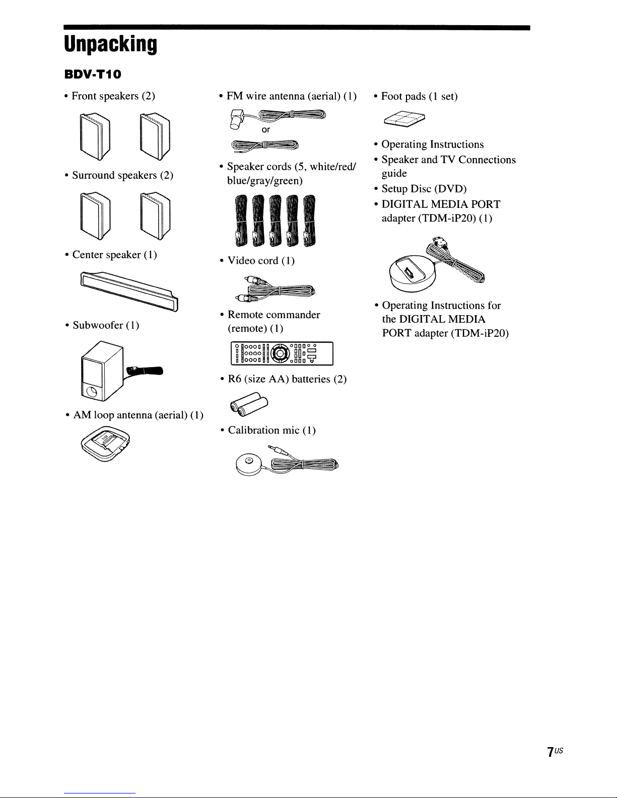
Unpacking
BDV·T10
• Front speakers (2)
• Surround speakers (2)
• Center speaker
• Subwoofer
(1)
(1)
• FM wire antenna (aerial)
~L5r]
I:::!
'~
• Speaker cords (5, white/red!
blue/gray/green)
or
_3
(1)
II1I1
• Video cord (1)
• Remote commander
0000
0000
(I)
.
gOo~
0000
~
(remote)
°1°000110°0000 °
~
o
• R6 (size AA) batteries (2)
• Foot pads(1set)
• Operating Instructions
• Speaker and TV Connections
guide
• Setup Disc (DVD)
• DIGITAL MEDIA PORT
adapter (TDM-iP20)
• Operating Instructions for
the DIGITAL MEDIA
PORT adapter (TDM-iP20)
(1)
• AM loop antenna (aerial)
(1)
• Calibration mic
(1)
US
7
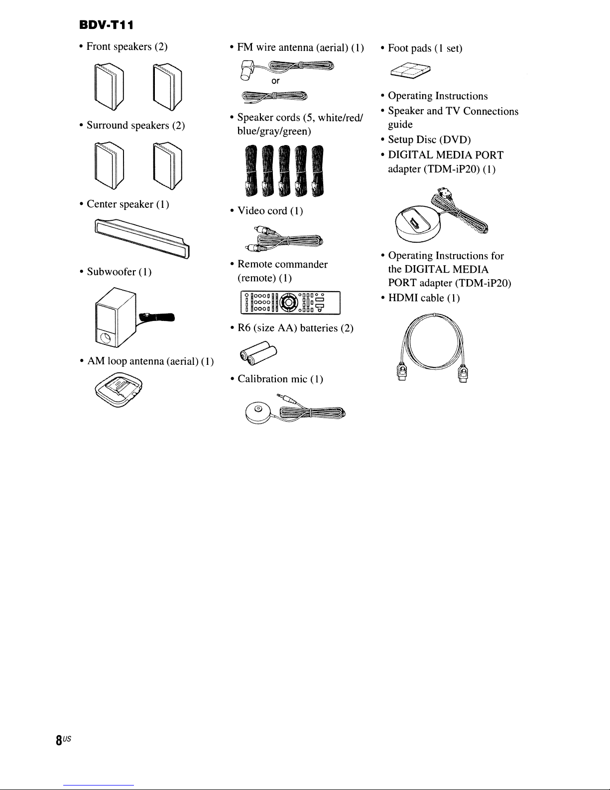
BDV·T11
• Front speakers (2)
• Surround speakers (2)
• Center speaker
• Subwoofer
(I)
(I)
• FM wire antenna (aerial)
Ht-~,,<e~
t:.!
• Speaker cords (5, white/redJ
blue/gray/green)
--.
or
(I)
IIII1
• Video cord (1)
• Remote commander
0000
(I)
.
gOo
oooo~
(remote)
°IOOODII~OOOO~
~
D oooD
• R6 (size AA) batteries (2)
• Foot pads (I set)
• Operating Instructions
• Speaker and TV Connections
guide
• Setup Disc (DVD)
• DIGITAL MEDIA PORT
adapter (TOM-iP20)
• Operating Instructions for
the DIGITAL MEDIA
PORT adapter (TDM-iP20)
• HDMI cable
(I)
(I)
• AM loop antenna (aerial)
(I)
• Calibration mic
(I)
US
8
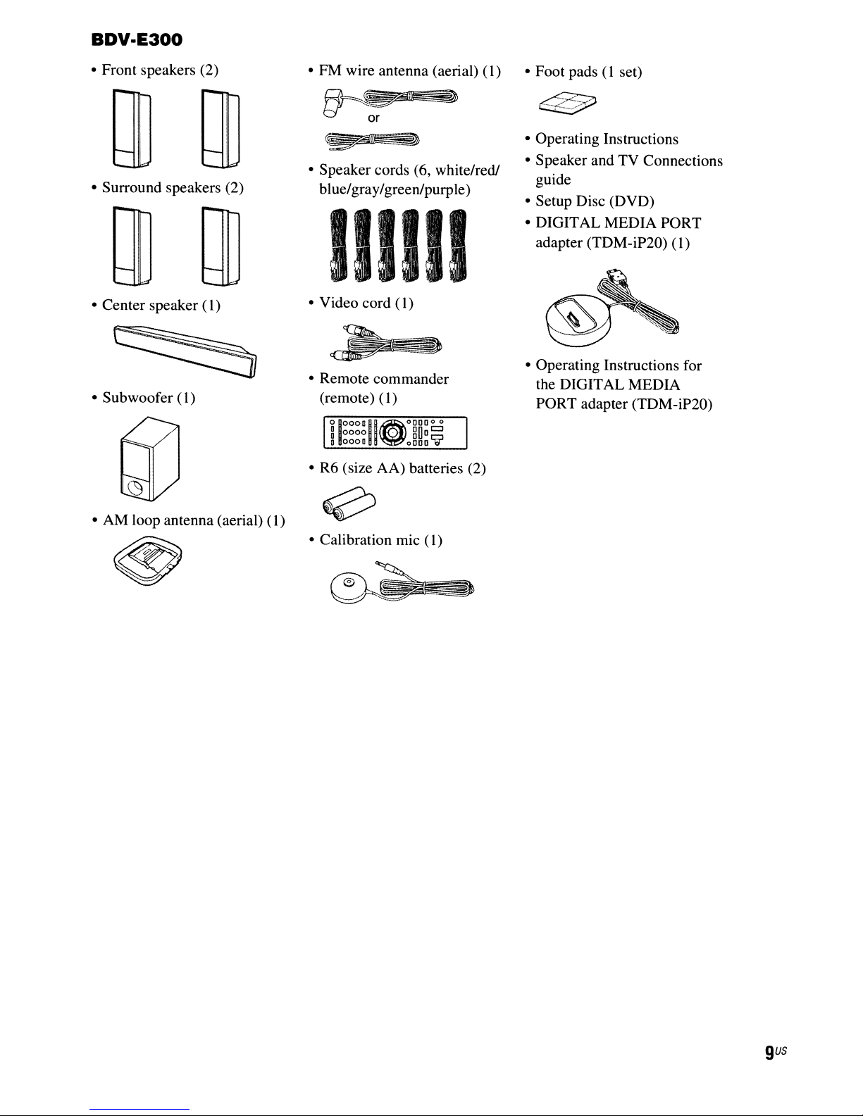
BDV·E300
• Front speakers (2)
• Surround speakers (2)
• Center speaker (
• Subwoofer (
1)
1)
• PM wire antenna (aerial)
~
• Speaker cords (6, white/red!
blue/gray/greenlpurple)
or
(1)
IIIIII
• Video cord
• Remote commander
(remote) (1)
°
10000
~
0000
a
0000
• R6 (size AA) batteries (2)
(1)
II~oDDDO
.
0
gUD~
oDDD
01
• Foot pads(1set)
• Operating Instructions
• Speaker and TV Connections
guide
• Setup Disc (DVD)
• DIGITAL MEDIA PORT
adapter (TDM-iP20)
• Operating Instructions for
the DIGITAL MEDIA
PORT adapter (TDM-iP20)
(1)
• AM loop antenna (aerial)
(1)
• Calibration mic
(1)
gus
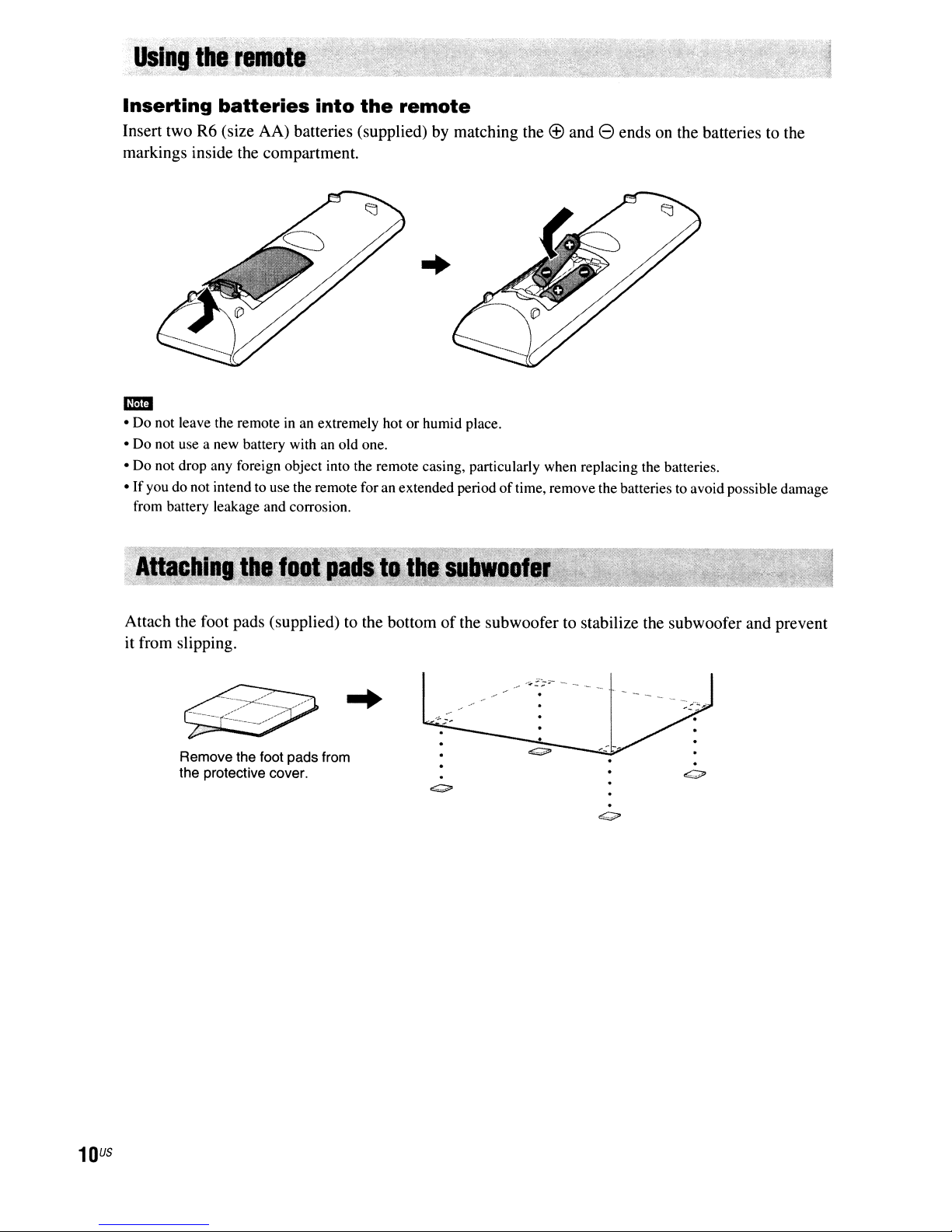
Inserting
Insert two R6 (size AA) batteries (supplied) by matching the
markings inside the compartment.
batteries
into
the
remote
(£)
and 8 ends on the batteries to the
..
m:m
• Do not leave the remoteinan extremely hot or humid place.
• Do not use a new battery with
• Do not drop any foreign object into the remote casing, particularly when replacing the batteries.
•
If
you do not intend to use the remote for an extended periodoftime, remove the batteries to avoid possible damage
from battery leakage and corrosion.
an
old one.
Attach the foot pads (supplied) to the bottomofthe subwoofer to stabilize the subwoofer and prevent
it from slipping.
Remove the foot pads from
the protective cover.
.
~
US
10
Index
to
Parts
and
Control
For more information, refer to the pages
indicated in parentheses.
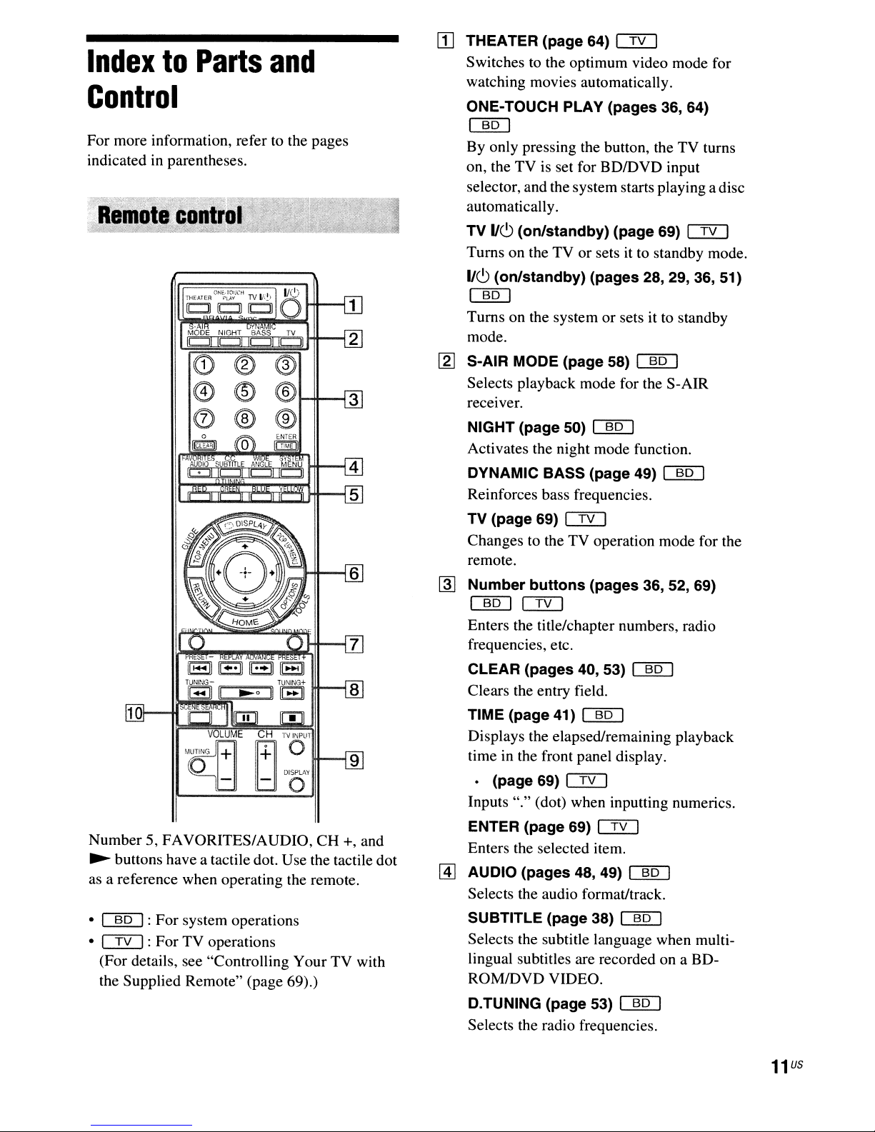
[]
THEATER (page 64) CI2:J
Switches to the optimum video mode for
watching movies automatically.
ONE-TOUCH PLAY (pages 36, 64)
a.gJ
By only pressing the button, the TV turns
on, the
selector, and the system starts playing
automaticall
TV
Turns on the TV or sets it to standby mode.
IJ~
a.gJ
Turns on the systemorsets it to standby
mode.
TV
is set for BDIDVD input
y.
IJ~
(on/standby) (page 69) CI2:J
(on/standby) (pages 28, 29, 36, 51)
adisc
(1)
@ @1-+I---13
0®®
[g] S-AIR MODE (page 58)
Selects playback mode for the S-AIR
receiver.
NIGHT (page 50)
Activates the night mode function.
DYNAMIC BASS (page 49)
Reinforces bass frequencies.
TV
(page 69) CI2:J
Changes to the TV operation mode for the
remote.
~
Number buttons (pages 36, 52, 69)
a.gJ
Enters the title/chapter numbers, radio
frequencies, etc.
CLEAR (pages 40, 53)
Clears the entry field.
TIME (page 41)
Displays the elapsed/remaining playback
time in the front panel display.
em
[QQ]
a.gJ
[QQ]
emu
emu
Number 5, FAVORITES/AUDIO,
~
buttons have a tactile dot. Use the tactile dot
as a reference when operating the remote.
•
a.gJ:
For system operations
• CI2:J: For TV operations
(For details, see "Controlling Your
the Supplied Remote" (page 69).)
CH
+, and
TV
with
• (page 69)
Inputs "." (dot) when inputting numerics.
ENTER (page 69)
Enters the selected item.
[1] AUDIO (pages 48, 49)
Selects the audio format/track.
SUBTITLE (page 38)
Selects the subtitle language when multilingual subtitles are recorded on a BDROMIDVD VIDEO.
D.TUNING (page 53)
Selects the radio frequencies.
em
em
emu
[QQ]
[QQ]
11
US
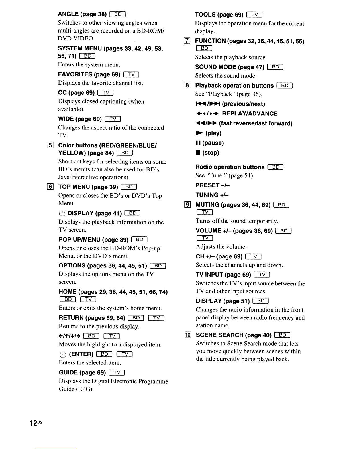
ANGLE (page 38)
Switches to other viewing angles when
multi-angles are recorded on a
DVDVIDEO.
SYSTEM MENU (pages 33, 42, 49, 53,
56,71)
Enters the system menu.
FAVORITES (page 69) Cf2J
Displays the favorite channel list.
CC (page 69) Cf2J
Displays closed captioning (when
available).
WIDE (page 69)
Changes the aspect ratioofthe connected
TV.
[ID
Color buttons (RED/GREEN/BLUEt
YELLOW) (page 84)
Short cut keys for selecting items on some
BD's
Java interactive operations).
[ID
TOP MENU (page 39)
Opens or closes the
Menu.
[]Q]
menus (can also be used for
o DISPLAY (page 41)
Displays the playback information on the
TV screen.
POP UP/MENU (page 39)
Opens or closes the
Menu, or the
OPTIONS (pages 36, 44, 45, 51)
Displays the options menu on the TV
screen.
HOME (pages 29, 36, 44, 45, 51, 66, 74)
[]Q]
Enters or exits the system's home menu.
RETURN (pages 69, 84)
Returns to the previous display.
+-/'t'/~I-+
Moves the highlight to a displayed item.
()
Enters the selected item.
Cf2J
[]QJ
(ENTER)
[]Q]
Cf2J
BD'sorDVD's
BD-ROM's
DVD's
Cf2J
[]Q]
BD-ROMI
[]QJ
[]Q]
[]QJ
[]QJ
menu.
[]QJ
Cf2J
BD's
Top
Pop-up
[]QJ
Cf2J
TOOLS (page 69) Cf2J
Displays the operation menu for the current
display.
[f]
FUNCTION (pages 32,
36,44,45,
[]Q]
Selects the playback source.
SOUND MODE (page 47)
Selects the sound mode.
Playback operation buttons
lID
See "Playback" (page 36).
~
/~
(previous/next)
..-/-
..
REPLAY/ADVANCE
....
/~
(fast reverselfast forward)
~
(play)
II
(pause)
• (stop)
Radio operation buttons
See "Tuner" (page 51).
PRESET
TUNING
MUTING (pages 36, 44, 69)
lID
+/-
+/-
[]QJ
[]Q]
[]QJ
[]QJ
Cf2J
Turns off the sound temporarily.
VOLUME
+/-
(pages 36, 69)
[]QJ
Cf2J
Adjusts the volume.
CH
+/-
(page 69) Cf2J
Selects the channels up and down.
TV INPUT (page 69) Cf2J
TV's
Switches the
TV and other input sources.
DISPLAY (page 51)
Changes the radio information
panel display between radio frequency and
station name.
[1Q]
SCENE SEARCH (page 40)
Switches to Scene Search mode that lets
you move quickly between scenes within
the title currently being played back.
input source between the
[]QJ
in
[]Q]
51,55)
the front
GUIDE (page 69) Cf2J
Displays the Digital Electronic Programme
Guide (EPG).
US
12

1 2
IC!!::J
\
\/
I
III
n
8 7 6
[I]
11(9
(on/standby) (page 36)
Turns on the unit, or sets to standby mode.
[ZJ
Play
operation
~
(play)
Starts or re-starts playback.
Plays a slideshow when a disc containing
IPEG image files
• (stop)
Stops playback and remembers the stop
point (resume point).
The resume point for a title/track is the last
point you played
photo folder.
buttons
is
inserted.
or
the last photo for a
1-
(page 36)
.......
,4""
.
l~~~
_.
.
_
...
-
_.
__
..
._.
_.
i
==
-
..
--
I
1/
I
~
5 4
@]
S-AIR
indicator
Lights up when the S-AIR transceiver is
inserted in the unit and the system transmits
sound.
[1] VIRTUAL
7.1
Lights up while virtual 7.1 ch decoding is
activated.
~
Power
indicator
Lights up while the system is turned on.
[§]
[l]
[ID
Front
Disc
m
(remote
panel
tray
(page 36)
CH
display
sensor)
3
indicator
(page 33)
FUNCTION
Selects the playback source.
VOLUME
+/-
Adjusts the system's volume.
~
(open/close)
Opensorcloses the disc tray.
13
US
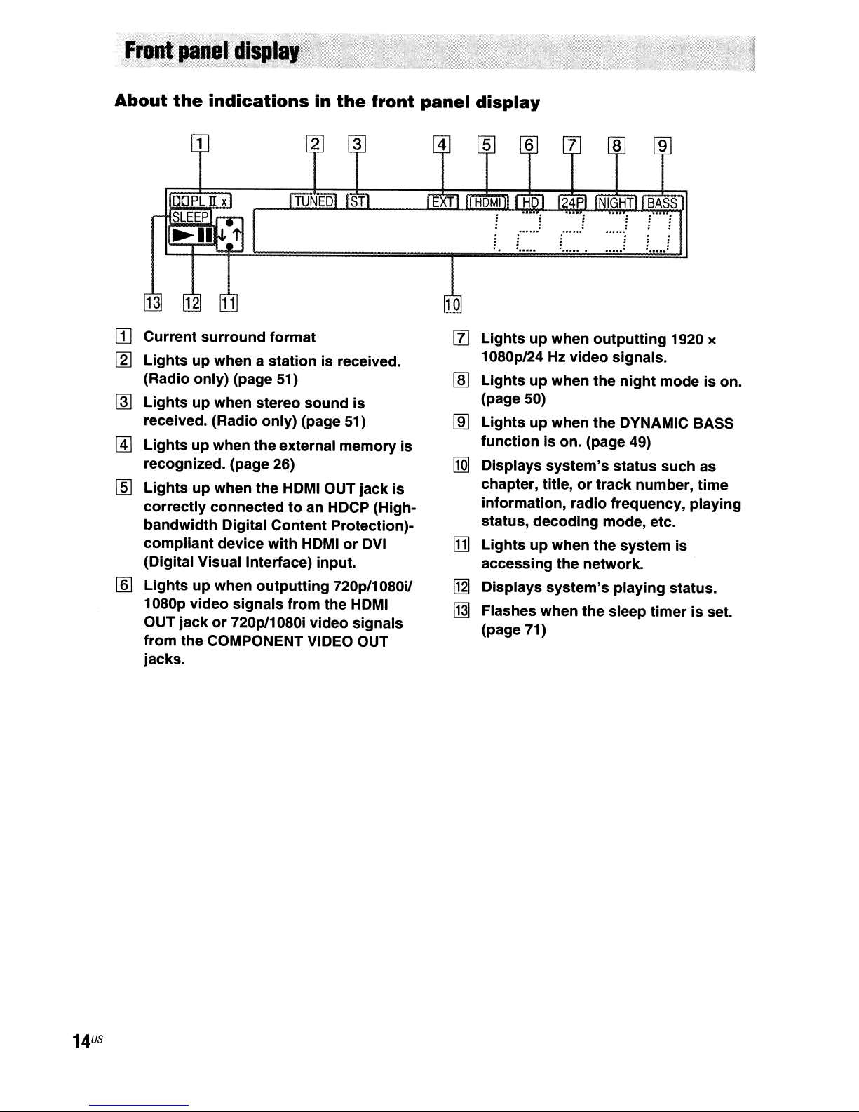
About
13 12
the
indications
in
the
front
panel
display
9
BASS
- .
[II
Current
[g]
Lightsupwhenastationisreceived.
(Radio
@]
Lightsupwhen
received. (Radio
@]
Lightsupwhen
recognized. (page 26)
[§]
Lightsupwhen
correctly
bandwidth
compliant
(Digital Visual Interface) input. accessing
[§]
Lightsupwhen
1080p
OUT
from
jacks.
surround
only)
connectedtoan HDCP (High-
Digital Content Protection)-
device
video
jackor720pl1080i
the COMPONENT VIDEO OUT
format
(page 51)
stereo
only)
the
external
the
HDMI OUT
with
outputting
signals
sound
(page 51)
memory
HDMIorDVI
720p/1080i/
from
the HDMI
video
is
jack
signals
is
is
[l]
Lightsupwhen
1080p/24 Hz
Lightsupwhen
lID
(page 50)
lID
functionison. (page 49)
[jg]
ITIJ
[1gJ
[j]]
outputting
video
Lightsupwhen
Displays
chapter, title,ortrack
information, radio frequency,
status,
Lightsupwhen
Displays
Flashes
(page 71)
system's
decoding
the
system's
when
signals.
the
night
the
DYNAMIC BASS
status
mode, etc.
the
system
network.
playing
the
sleep
1920 x
modeison.
such
number,
status.
timerisset.
as
time
playing
is
US
14
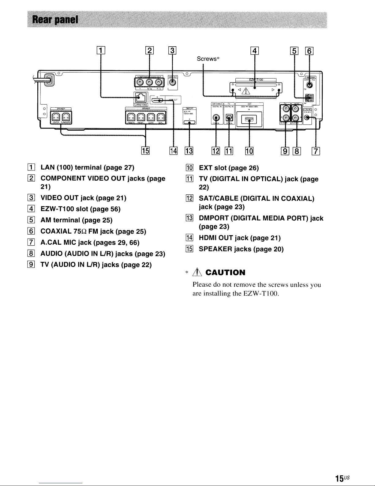
1
Screws*
4
[I]
LAN (100)
[gJ
COMPONENT VIDEO OUT
21)
~
VIDEO OUT
@]
EZW-T100
lID
AM
terminal
lID
COAXIAL 75Q
[f)
A.CAL
I]]
AUDIO (AUDIOINUR)
MIC
terminal
jack
slot
(page 56)
(page 25)
FM
jack
(page 27)
jacks
(page 21)
jack
(page 25)
(pages 29, 66)
jacks
15
(page
(page 23)
14
o
I1Q]
EXT
slot
(page 26)
[j]
TV (DIGITALINOPTICAL)
22)
ng]
SAT/CABLE (DIGITALINCOAXIAL)
jack
(page 23)
~
DMPORT (DIGITAL MEDIA PORT)
(page 23)
[HJ
HDMI OUT
II§]
SPEAKER
jack
jacks
• 100
(page 21)
(page 20)
jack
(page
jack
lID
TV (AUDIOINUR)
jacks
(page
22)
*
LL
CAUTION
Please do not remove the screws unless you
are installing the
EZW
-T 100.
15
US
Getting
Started
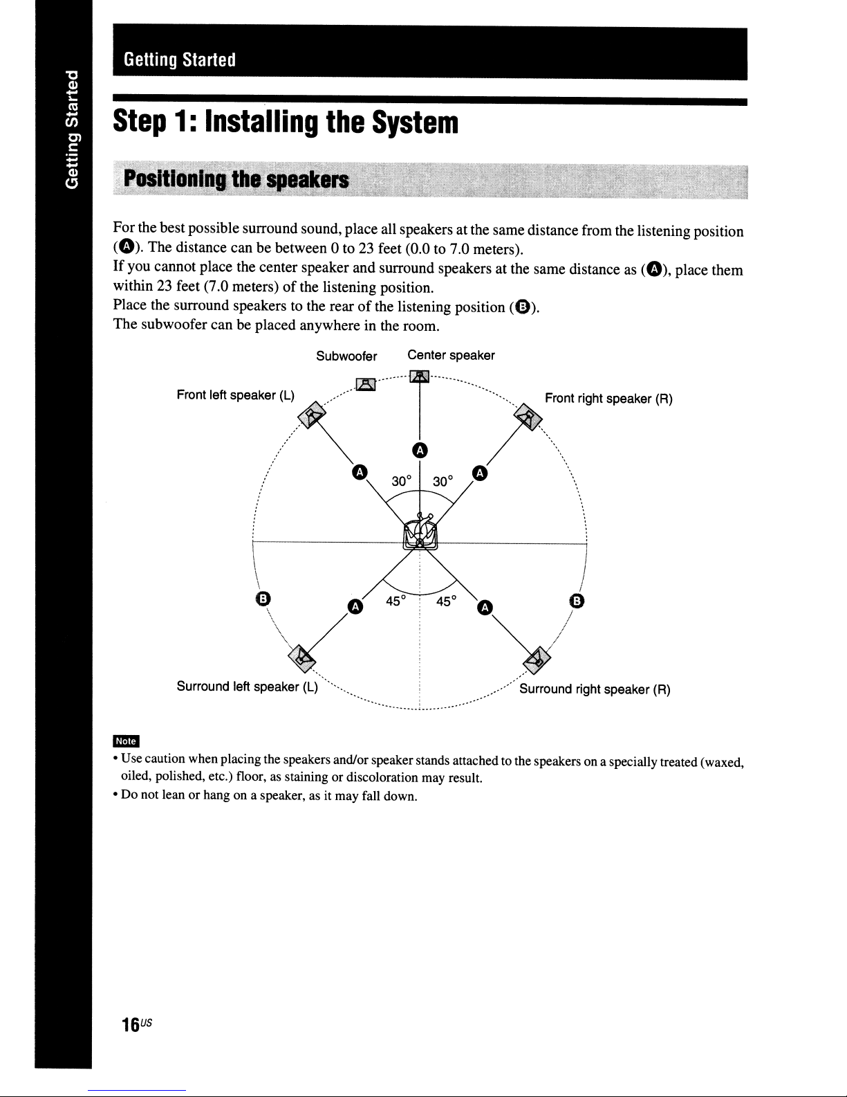
Step
Forthe best possible surround sound, place all speakersatthe same distance from the listening position
(0).
If
you cannot place the center speaker and surround speakers at the same distance
within 23 feet (7.0 meters)
Place the surround speakers to the rear
The subwoofer can be placed anywhere in the room.
1:
Installing
The distance canbebetween 0 to23feet (0.0 to 7.0 meters).
of
From
le«speaker
(L)~llSlr,.~rom
...
/:/
the
the listening position.
Subwoofer Center speaker
~
System
of
the listening position
0 /
30
0
300
0
(0).
0
as
(0),
r~ht
speaker
(AI
...
..........
place them
Surround left speaker
am
• Use caution when placing the speakers and/or speakerstands attached to the speakers on a specially treated (waxed,
oiled, polished, etc.) floor,
or
• Do not lean
US
16
hang on a speaker, as it may fall down.
as
(L)
",
staining or discoloration may result.
.....
/ Surround right speaker (R)
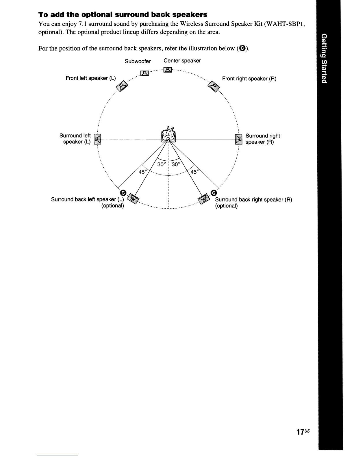
To
add
the
optional
You can enjoy 7.1 surround sound by purchasing the Wireless Surround Speaker Kit (WAHT-SBP1,
optional). The optional product lineup differs depending on the area.
surround
back
speakers
For the positionofthe surround back speakers, refer the illustration below
Subwoofer
1E
Front left speaker (L) Front right speaker (R)
,
....
,",::
"".'"
. . " .
~
.
. .
.
.
. .
. .
. .
. ,
. .
. .
Surround left
speaker (L)
Surround back left speaker (L)
1tJ!4----------1~btlI-------
(9
(optional)
Center speaker
I3l-
.
~.1~:.""
'.0:"'.
.
.
.
(9
'..~Surround back right speaker (R)
(optional)
«9).
Surround right
speaker(R)
17
US
Caution
• Contact a screw shoporinstaller regarding the wall material or screws to be used.
• Use screws that are suitable for the wall material and strength. As a plaster board wall is especially fragile, attach
the screws securely to a beam and fasten them to the wall. Install the speakers on a vertical and flat wall where
reinforcement is applied.
• Sony is not responsible for accidents or damage caused by improper installation, insufficient wall strength or
improper screw installation, natural calamity, etc.
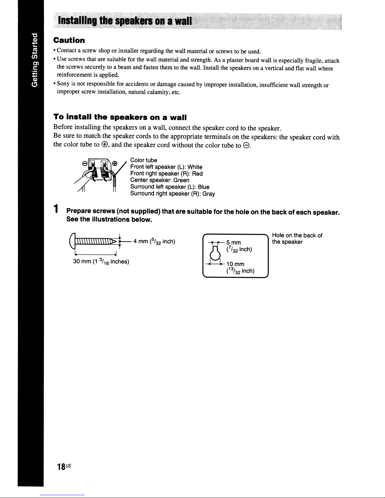
To
install
Before installing the speakers on a wall, connect the speaker cord to the speaker.
Be sure to match the speaker cords to the appropriate terminals on the speakers: the speaker cord with
the color tube to
the
speakers
~,
and the speaker cord without the color tube to
Color tube
Front left speaker (L): White
Front right speaker (R): Red
Center speaker: Green
Surround left speaker (L): Blue
Surround right speaker (R): Gray
on a
wall
8.
1 Preparescrews (not supplied) that are suitable for the hole on the back
See the illustrations below.
Hole on the back of
G\\\\\\\\\\\\\\1>
~
30 mm
(1
3/
inches)
16
.1
~
4 mm
(5/
32
inch)
the speaker
of
each speaker.
US
18
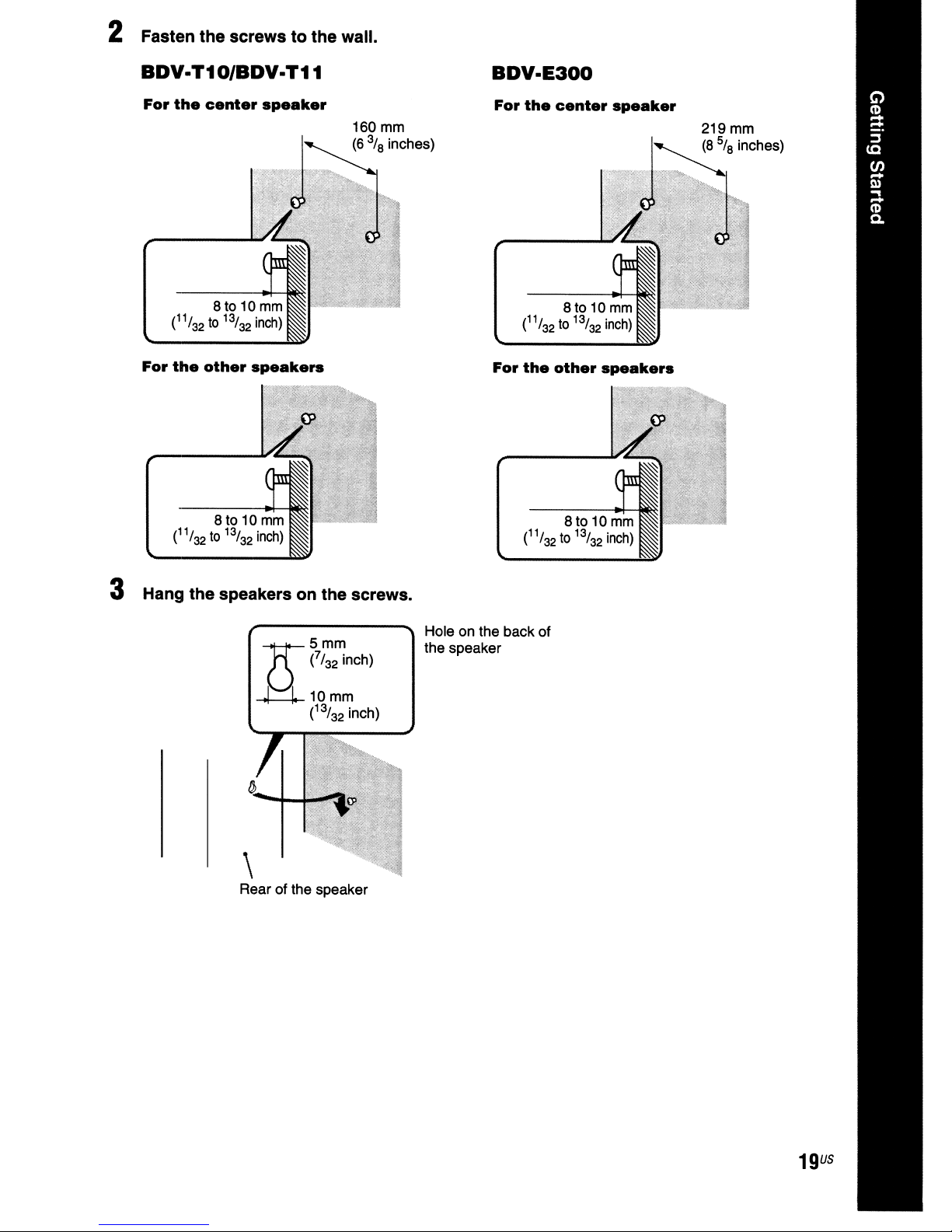
2 Fasten the screws to the wall.
BDY.T10/BDY-T11
For
the
For
the
center
other
speaker
speakers
160
(6%
mm
inches)
BDY·E300
For
the
center
For
the
other
speaker
speakers
219mm
(8
5ta
inches)
3 Hang the speakers on the screws.
\
Rear of the speaker
Holeonthe back of
the speaker
19
U5
Step
For connecting the system, read the information on the following pages.
Do not connect the AC power cord (mains lead)
connections are made.
• When you connect another component with a volume control, tum down the volumeofthe other components to a
-
level where sound is not distorted.
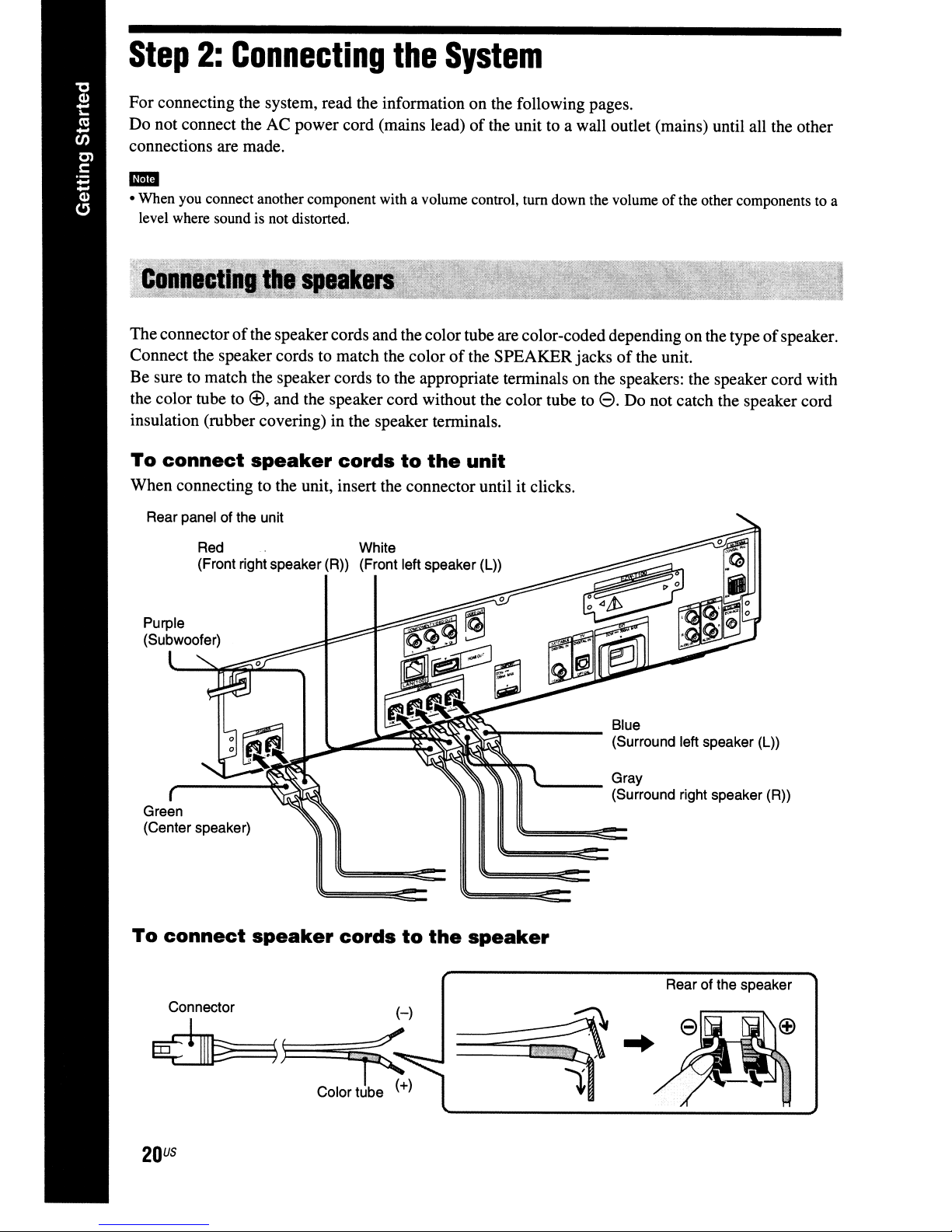
Theconnectorofthe speakercords and the color tube are color-coded depending on the typeofspeaker.
Connect the speaker cords to match the color
Be sure to match the speaker cords to the appropriate terminals on the speakers: the speaker cord with
the color tube to
insulation (rubber covering) in the speaker terminals.
To
When connecting to the unit, insert the connector until it clicks.
2:
connect
Connecting
~,
and the speaker cord without the color tube to8.Do not catch the speaker cord
speaker
cords
the
to
the
System
of
the unit to a wall outlet (mains) until all the other
of
the SPEAKER jacksofthe unit.
unit
Rear panel of the unit
Red White
(Front right speaker
Green
(Center speaker)
To
connect
speaker
(R»
(Front left speaker (L»
cords
to
the
speaker
'----
Blue
(Surround left speaker (L»
Gray
(Surround right speaker (R»
Connector
~))::::::l
U5
20
~
Rear of the speaker
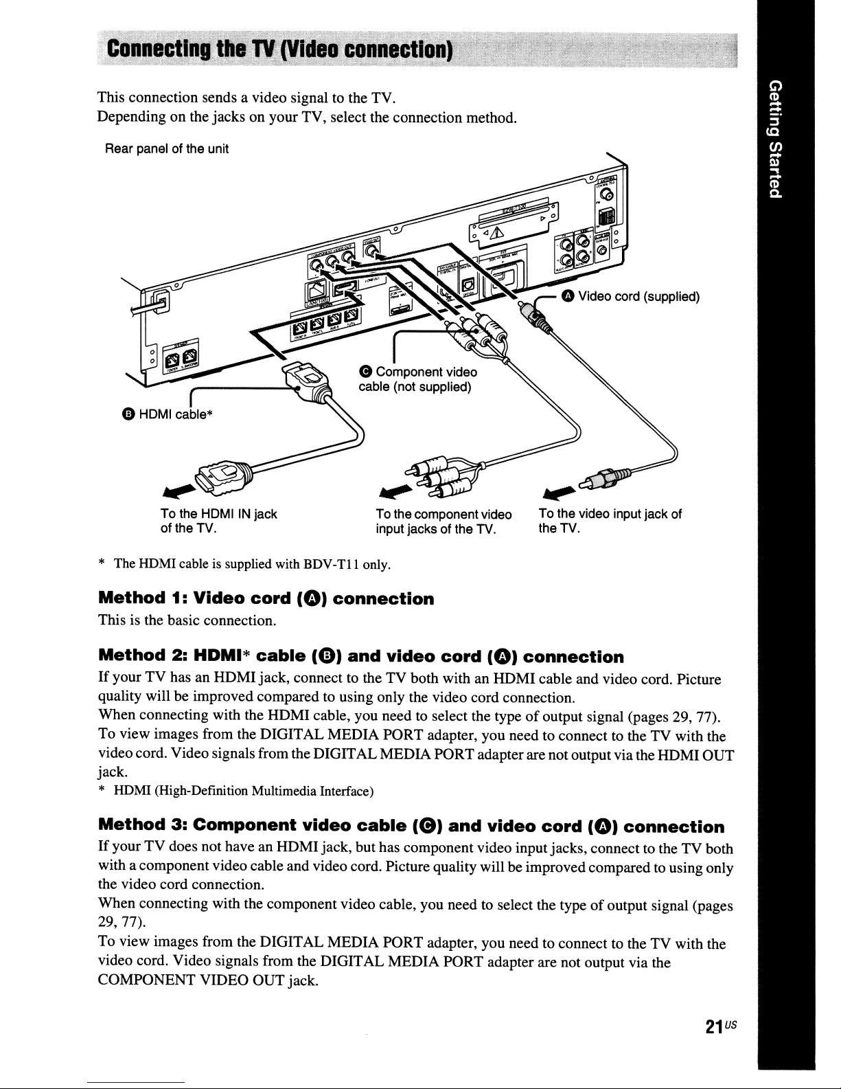
This connection sends a video signal to the TV.
Depending
Rear panel of the unit
on
the jacks on your TV, select the connection method.
.,.
HDMIIN
To the
of the TV.
* The HDMI cable is supplied with
Method
This is the basic connection.
Method
If
your TV has an HDMI jack, connect to the TV both with an HDMI cable and video cord. Picture
quality will be improved compared to using only the video cord connection.
When connecting with the HDMI cable, you need to select the type
To view images from the DIGITAL MEDIA PORT adapter, you need to connect to the TV with the
video cord. Video signals from the DIGITAL MEDIA PORT adapterare not outputvia the HOMI OUT
jack.
1:
2:
Video
HDMI*
jack
cord
cable
BDV-TlI
(0)
connection
(0)
To the component video
input jacks of the TV.
only.
and
video
cord
(0)
To the video input jack of
the TV.
connection
of
output signal (pages 29, 77).
* HDMI (High-Definition Multimedia Interface)
Method
If
your
with a component video cable and video cord. Picture quality will be improved compared to using only
the video cord connection.
When connecting with the component video cable, you need to select the type
29,77).
To view images from the DIGITAL MEDIA PORT adapter, you need to connect to the TV with the
video cord. Video signals from the DIGITAL MEDIA PORT adapter are not output via the
COMPONENT VIDEO OUT jack.
3:
Component
TV
does not have an HOMI jack, but has component video input jacks, connect to the TV both
video
cable
(e)
and
video
cord
(0)
connection
of
output signal (pages
21
us
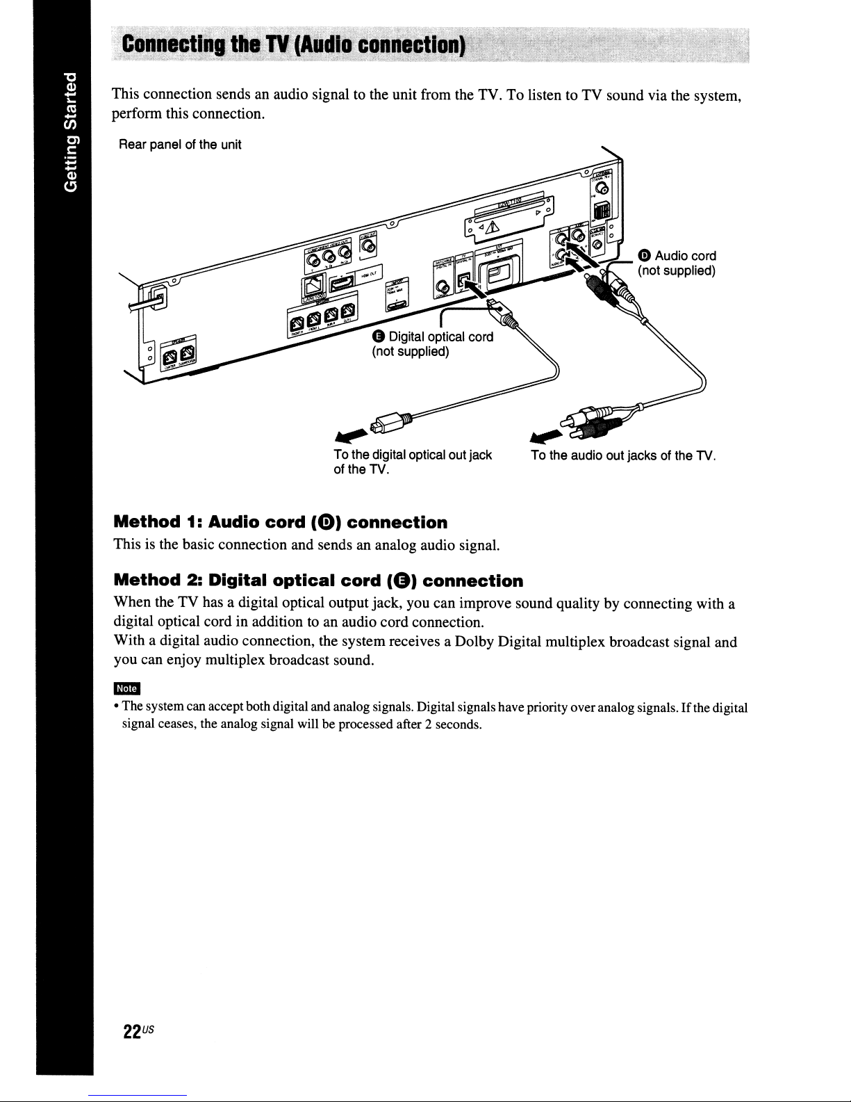
This connection sends an audio signal to the unit from the TV. To listen to TV sound via the system,
perform this connection.
Rear panel of the unit
.".
To the digital optical out jack
of the TV.
Method
This is the basic connection and sends an analog audio signal.
Method
When the TV has a digital optical output jack, you can improve sound quality by connecting with a
digital optical cord in addition
With a digital audio connection, the system receives a Dolby Digital multiplex broadcast signal and
you can enjoy multiplex broadcast sound.
1: Audio
2:
Digital
cord
optical
(0)
connection
cord
to
an audio cord connection.
(8)
connection
.".
To the audio out jacks of the TV.
om
•
The
systemcan accept bothdigital and analog signals. Digital signals have priority
signal ceases, the analog signal will
be
processed after 2 seconds.
over
analog signals.
Ifthe
digital
US
22
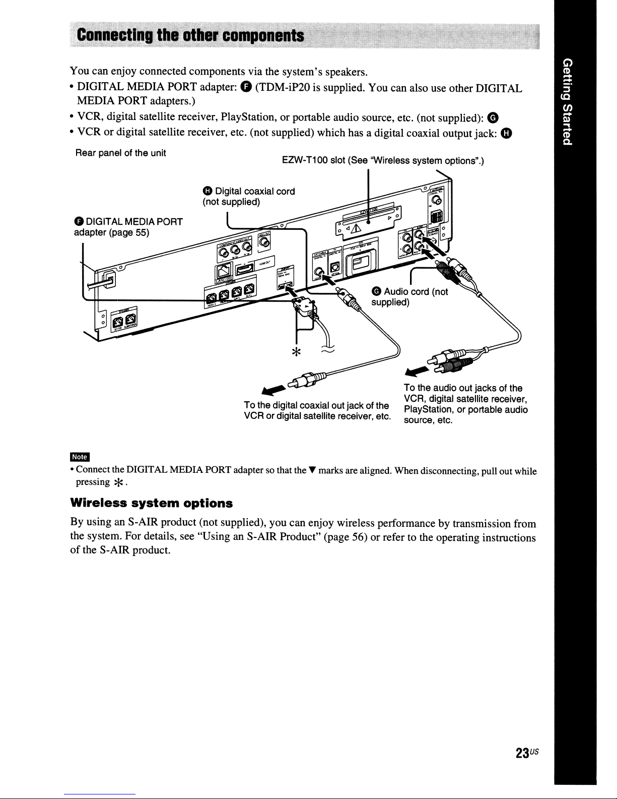
You can enjoy connected components via the system's speakers.
4)
• DIGITAL MEDIA PORT adapter:
MEDIA PORT adapters.)
• VCR, digital satellite receiver, PlayStation, or portable audio source, etc. (not supplied):
• VCR or digital satellite receiver, etc. (not supplied) which has a digital coaxial outputjack:
(TDM-iP20 is supplied. You can also use other DIGITAL
CD
CD
Rear panel of the unit
G DIGITAL MEDIAPORT
adapter (page 55)
EZW-T100 slot (See 'Wireless system options".)
oDigital coaxial cord
(not supplied)
.",.
To
the digital coaxial out jack ofthe
VCR or digital satellite receiver, etc.
To the audio out jacks of the
VCR, digital satellite receiver,
PlayStation,
source, etc.
or
portable audio
• Connect the DIGITAL MEDIA PORTadapter so that the~marks are aligned. When disconnecting, pull out while
-
pressing
Wireless
By using an S-AIR product (not supplied), you can enjoy wireless performance by transmission from
the system. For details, see "Using an S-AIR Product" (page 56) or refer to the operating instructions
of
the S-AIR product.
*.
system
options
23
US
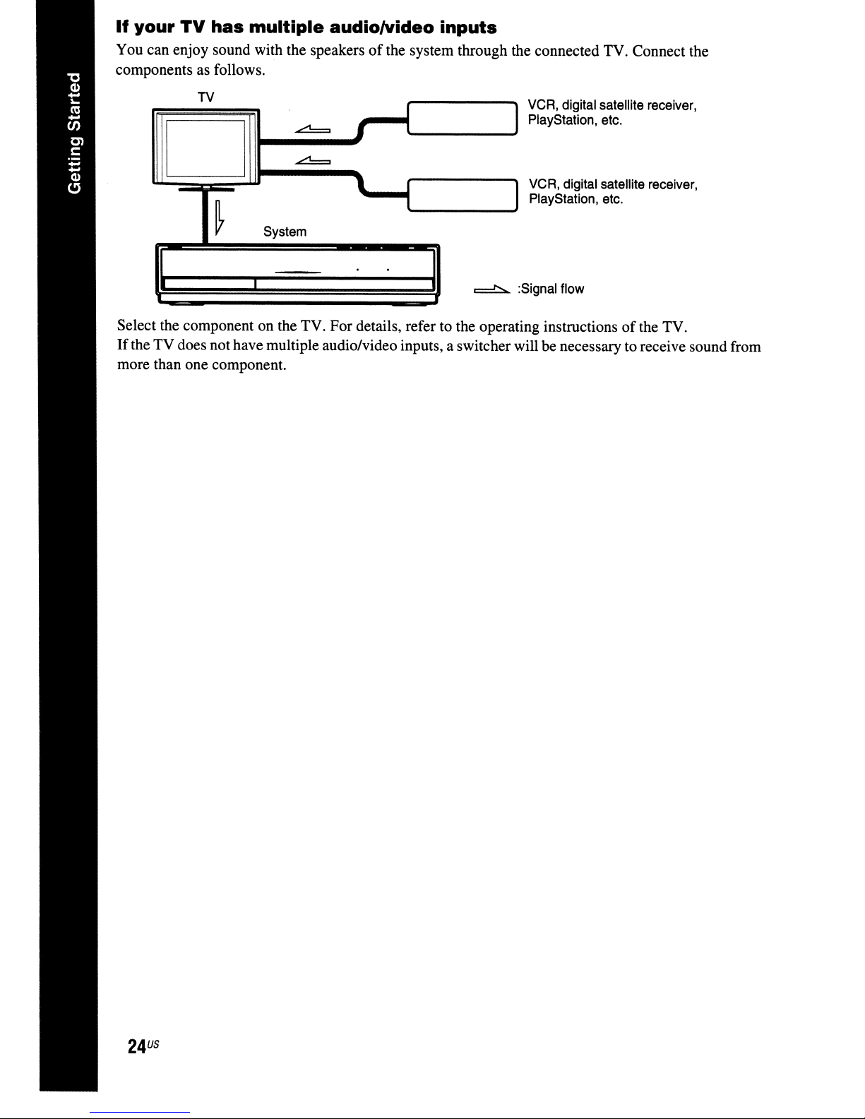
If
your
You can enjoy sound with the speakersofthe system through the connected TV. Connect the
components
TV
has
as
follows.
multiple
audio/Video inputs
TV
~
~
I
I
I
D
l.
~
Select the component on the TV. For details, refer to the operating instructionsofthe TV.
If
the TV does not have multiple audio/video inputs, a switcher will be necessary to receive sound from
more than one component.
System
I
I
l
==:t::...
VCR, digital satellite receiver,
PlayStation, etc.
I
VCR, digital satellite receiver,
PlayStation, etc.
I
:Signal flow
US
24
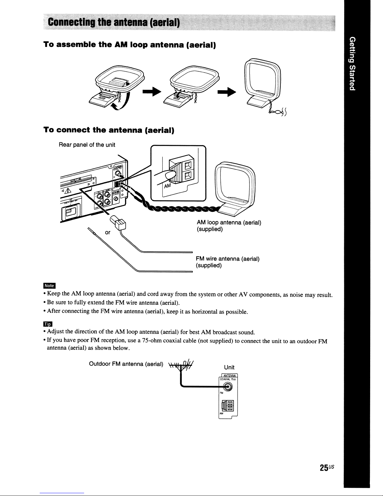
To
assemble
To
connect
Rear panel of the unit
the
the
AM
loop
antenna
antenna
(aerial)
(aerial)
AM loop antenna (aerial)
(supplied)
FM wire antenna (aerial)
(supplied)
..
• Keep the AM loop antenna (aerial) and cord away from the systemorother AV components, as noise may result.
• Be sure to fully extend the FM wire antenna (aerial).
it
• After connecting the FM wire antenna (aerial), keep
IiI'!II
• Adjust the directionofthe AM loop antenna (aerial) for best AM broadcast sound.
•
If
you have poor FM reception, use a 75-ohm coaxial cable (not supplied) to connect the unit toanoutdoor FM
antenna (aerial) as shown below.
Outdoor FM antenna (aerial)
as horizontal as possible.
Unit
II
AM
25
US
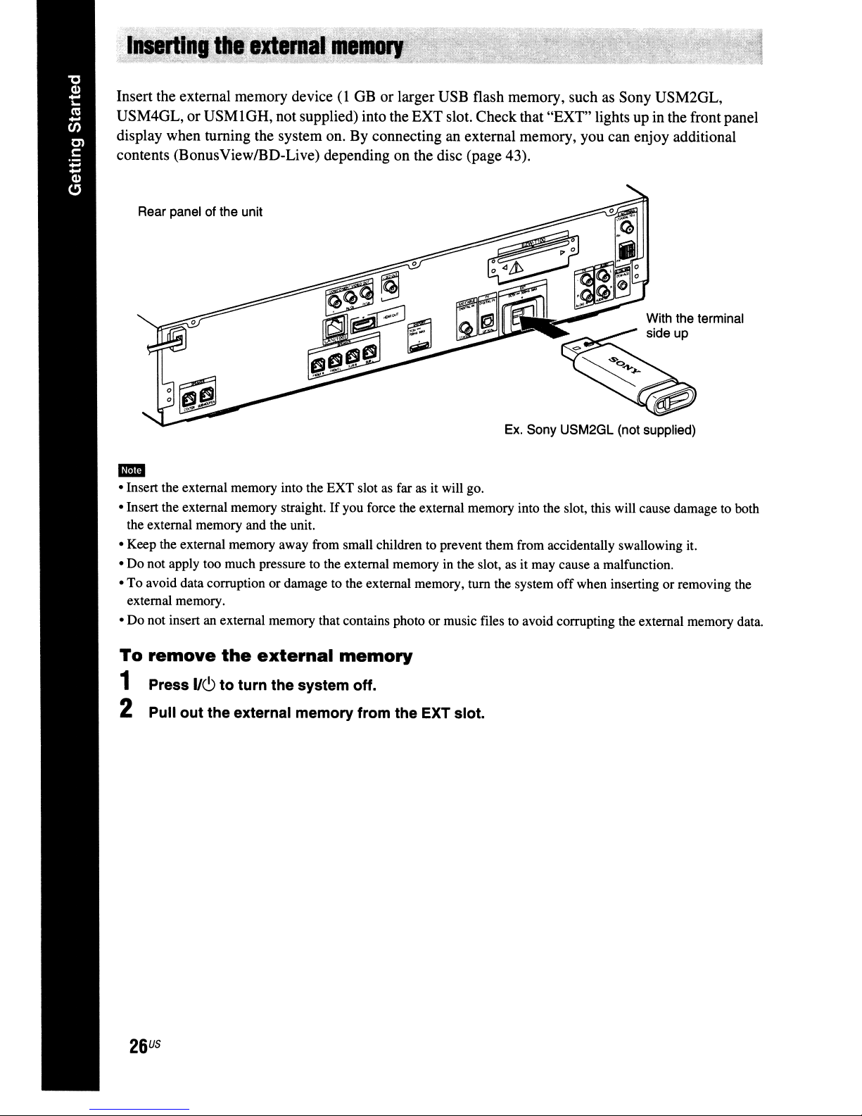
Insert the external memory device(IGB or larger USB flash memory, suchasSony USM2GL,
GR,
USM4GL, or USM 1
display when turning the system on. By connecting an external memory, you can enjoy additional
contents (BonusViewIBD-Live) depending on the disc (page 43).
Rear panel of the unit
not supplied) into the EXT slot. Checkthat "EXT" lights up in the front panel
Ex. Sony USM2GL (not supplied)
..
• Insert the external memory into the EXT slot as far as it will go.
• Insert the external memory straight.Ifyou force the external memory into the slot, this will cause damage to both
the external memory and the unit.
• Keep the external memory away from small children to prevent them from accidentally swallowing it.
• Do not apply too much pressure to the external memoryinthe slot,asit may cause a malfunction.
• To avoid data corruption or damage to the external memory, tum the system
external memory.
• Do not insert an external memory that contains photo or music files to avoid corrupting the external memory data.
off
when inserting or removing the
To
remove
1 Press
the
external
1/6
to turn the system off.
memory
2 Pull out the external memory from the EXT slot.
US
26
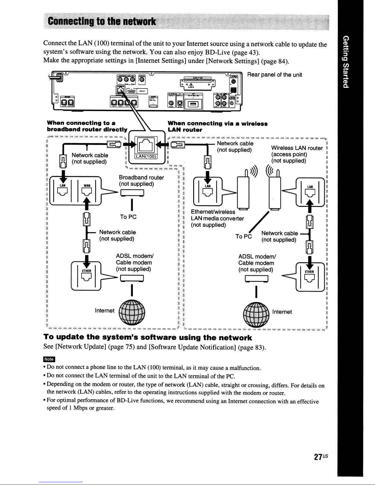
Connect the LAN(l00) terminalofthe unittoyour Internet source using a network cable to update the
system's software using the network. You can also enjoy BD-Live (page 43).
Make the appropriate settings in [Internet Settings] under [Network Settings] (page 84).
Rear panel of the unit
m~
~~~zmiiW
~~
fST=l
~II~I
When
~~
__
~._~_~~_~
H
fi
[
H
II
:
• Broadband router I I I
: (not supplied) : : I
• I I I I
[ I I
[ I I I
If
JI
II
! I I
• I no supp
II
II
!l
!l
: I
!l
JI
U (not supplied) I I (not supplied) I
!I
!I
:
II
Network cable : : To PC Network cable I
(not supplied) I I (not supplied) I
,
':-1
[ Wireless LAN router
['f
If
LAN(100
If
,.
...............•.....
To PC I I LAN mediaconverter I
ADSL modeml I I ADSL modem/
Cable modem : : Cable modem I
I I I I I I I
I:'
LAN
'~~_~~~~~~~_~~_M~~~_M~d~a_~~~d~~~
I . •
1 (not supplied) =
::t
connecting
router
...
:
I I
I I Ethernet/wireless
(t
I I
II
[
If
I I I
I I I
viaawire.e
Network cable
(not supplied) (access point) :
I'
d) :
Ie
»)))
~
••
((
I :
~
~
:
!I
II
~
If
I
•
II
:
Ii
! Imemel !!
:
~_*_MM
• I I ,
To
update
See [Network Update] (page 75) and [Software Update Notification] (page 83).
• Do not connect a phone line to the LAN
-
• Do not connect the LAN tenninal
• Depending on the modem or router, the type
the network (LAN) cables, refer to the operating instructions supplied with the modem or router.
• For optimal performance
speed
of
I Mbps or greater.
~_"
the
__N__
system's
of
BD-Live functions, we recommend using an Internet connection with an effective
,I;
• *
of
the unit to the LAN tenninalofthe PC.
__
._'
software
(l00)
tenninal, as it may cause a malfunction.
of
network (LAN) cable, straight or crossing, differs. For details on
~M
using
._._~.
the
.'
__
network
';',
Internet !
i • :
¥~
~_W.
~
__
*
US
27
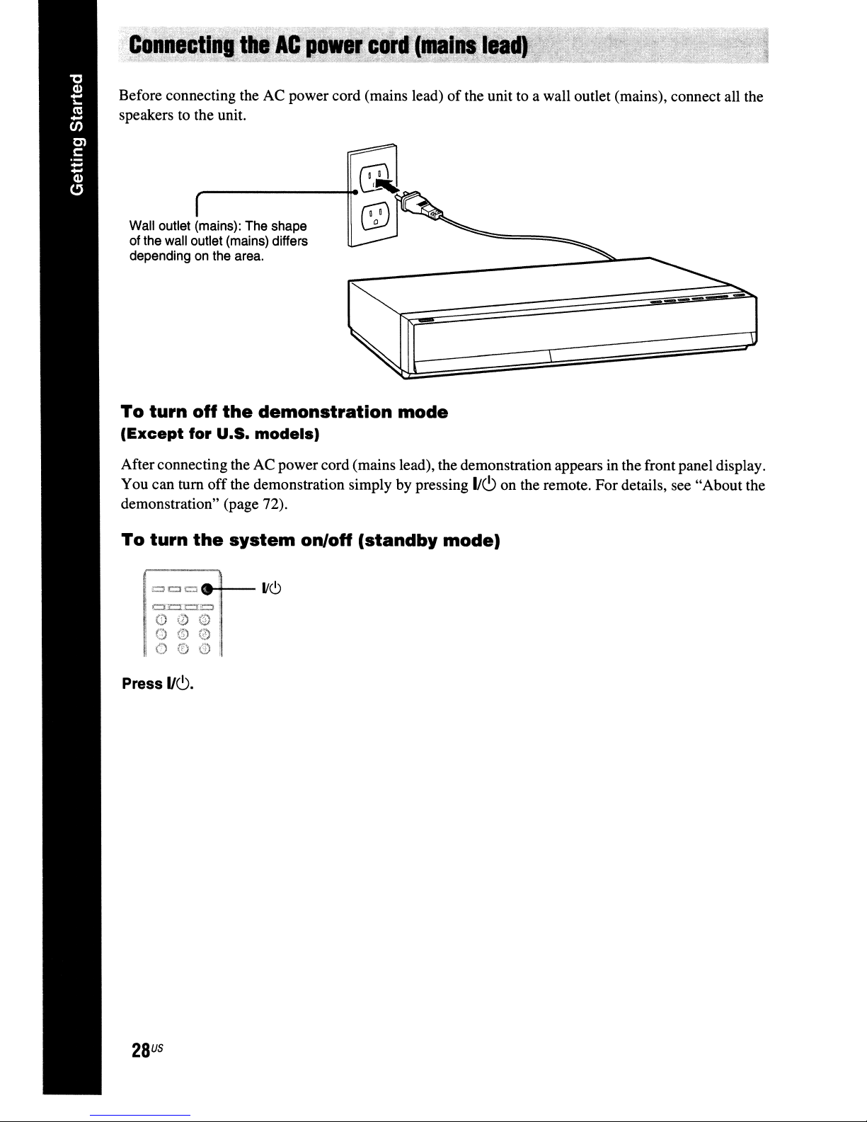
Before connecting the AC power cord (mains lead)ofthe unit to a wall outlet (mains), connect all the
speakers to the unit.
Wall outlet (mains): The shape
of the wall outlet (mains) differs
depending on the area.
To
turn
(Except
Afterconnecting the AC power cord (mains lead), the demonstration appears in the front panel display.
You can tum
demonstration" (page 72).
off
the
demonstration
for
U.S.
models)
off
the demonstration simply by pressing
mode
1Ic9
on the remote. For details, see "About the
To
Press
turn
=Cl=
00G
OG0
000
IIC).
the
system
1/6
on/off
(standby
mode)
US
28

Step
Easy
3:
Performing
Setup
the
Follow the Steps below to make the basic
adjustments for using the system.
Displayed items vary depending on the country
model.
5
Press e
or".
The setting message appears.
~
Easy
Setup
Set
the
items
below
•
Slliect
•
Select
•
Select
•
Slliect
•
Execute
that
all
reqUiredtouse
Items
maybechanged
tholVconnection
tholVlype
the
BO
Internet
tho
Standby
the
Auto
Calibration
cablltS.
etc.
have
Mode
Each01these
..
Check
method
Connection
been
Start
this
unit.
later
under
connected
"Setup:
and
then
stan.
[:::::.1:=.=:=
00®
000
:
000
1=
G =
1====
==:t::::r=
---
..........
+--
HOME
Turnonthe
1
Press
2
Switch
3
that
the signal
appears
The Easy Setup Display for OSD language
selection appears.
~
Easy
If
the
appear
Recall the Easy Setup Display. See "To
recall the Easy Setup Display" (page 32).
TV.
11(9
on
the unit.
the
input
on
the TV screen.
Setup·
050
Select
the
languagetobe
Easy
Setup
selectoronyourTVso
from
the system
English
Francais
Espanal
Portuguls
displayedbythis
Display
unit.
does
not
This message appears only when
performing the [Easy Setup] for the fIrst
time. It does not appear when performing
the [Easy Setup] accessed via the [Setup]
setting.
6 Press e
or".
The Setup Display for video cable selection
appears.
~
Easy
Setup·
TV
Connection
MetnOCl
Select
the
video
cable
connecting
this
unit
and
the
TV.
HOMI
Compo""nt
Video
..
Video
=
7
Press "'/",toselect the cable used
connect
Check the connectionofthe unit and
(page 21).
• When you connect the unit and TV with
an HDMI cable, select [HDMI], go to
Step
to match your
• When you connect the unit andTVwith a
component video cord, select
[Component Video], go to Step
the video output resolution to match your
TV.
• When you connect the unit and TV with
the video cord, select [Video] and go to
Step
the
unit
and TV.
8and set the video output resolution
TV.
9.
to
TV
8 and set
4 Press
"'/",toselect a language
050.
for
the
29
US
• When you do not connect the unit and TV with
-
an HOMI cable. you cannot select [HOMI].
• When connecting the HOMI OUT
jack
other video output jacks at the same time, select
[Component Video].
• For details about video output resolution, see
"Video Output Resolution" (page 99).
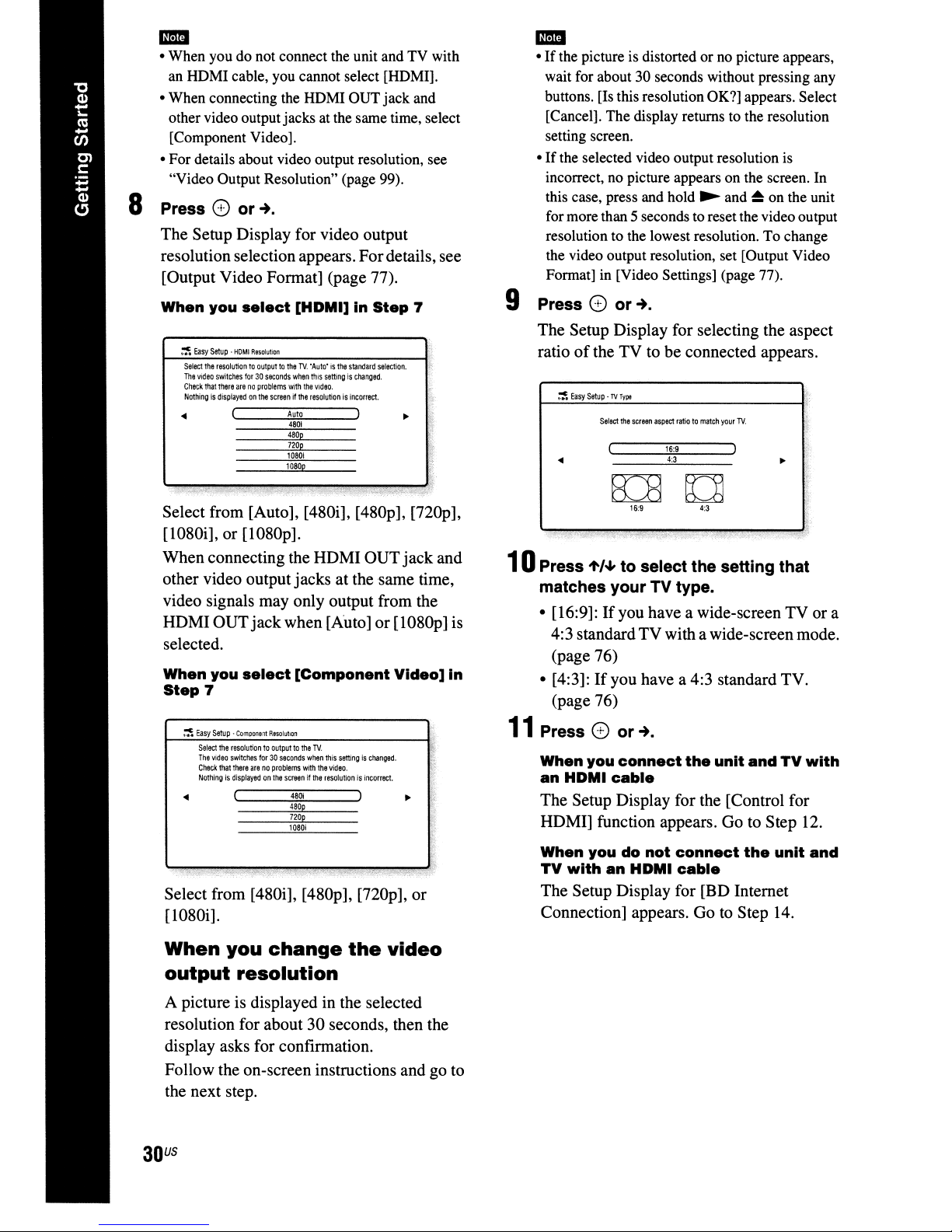
8 Press
CD
or".
The Setup Display for video output
resolution selection appears. Fordetails. see
[Output Video Fonnat] (page 77).
and
•
If
the picture is distorted or no picture appears.
-
wait for about 30 seconds without pressing any
buttons. [Is this resolution OK?] appears. Select
[Cancel]. The display returns to the resolution
setting screen.
•
If
the selected video output resolution is
incorrect. no picture appears on the screen. In
~
this case, press and hold
and~on the unit
for more than 5 seconds to reset the video output
resolution to the lowest resolution. To change
the video output resolution, set [Output Video
Format] in [Video Settings] (page 77).
When
you
~
Easy
Setup·
Select
the
resolutiontooutputtothe
The
video
switches
Check
that
there
NothingIsdisplayed
select
HOMI
Resollrtion
for30seconds
arenoproblems
on
tile
screenifthe
[HDMI]inStep
TV.
"Auto·isthe
when
with
Auto
4801
480p
720p
10801
1080p
standard
this
settingischanged.
the
video.
resolutionisincorrect.
selection.
7
~:,\
rL:
Select from [Auto]. [480i]. [480p]. [nOp].
[1080i]. or [1080p].
When connecting the HDMI OUT
jack
and
other video output jacks at the same time.
video signals may only output from the
or
HDMI OUTjackwhen [Auto]
[1080p] is
selected.
When
Step
you
7
~
Easy
Setup·
Component
Select
the
resolutiontooutputtothe
The
video
switches
Check
that
there
Nothingisdisplayedonthe
~
select
ResolullOrl
for30seconds
arenoproblems
[Component
TV.
when
this
settingischanged.
with
the
video.
screenifthe
resolutionisincorrect.
00
480p
720p
10801
Video]
•
in
9 Press
0)
or".
The Setup Display for selecting the aspect
of
ratio
10Press
the TV to be connected appears.
~
Easy
Setup·TVType
Select
the
screen
aspect
ratiotomateA
your
16:9
4:3
ELED
16:9
'to/oJ,
to select the setting that
4:3
TV.
matches yourTVtype.
• [16:9]:Ifyou have a wide-screen TV or a
4:3 standardTV with a wide-screen mode.
(page 76)
If
• [4:3]:
you have a 4:3 standard TV.
(page 76)
11
Press
When
an
0)
you
HDM.
or".
connect
cable
the
unit
andTVwith
The Setup Display for the [Control for
HDMI] function appears. Go to Step 12.
Select from [480i]. [480p].
[1080i].
When
output
you
change
resolution
A picture is displayed in the selected
resolution for about
30
display asks for confinnation.
Follow the on-screen instructions and go to
the next step.
US
30
[nOp],
the
or
video
seconds, then the
When
TV
youdonot
with
an
HDM.
connect
cable
the
unit
The Setup Display for [BD Internet
to
Connection] appears. Go
Step 14.
and
 Loading...