


Sony BDV-E870 Operating Instruction
4-178-243-11(1)
The software of this system may be updated in the future. To find out details on any
available updates, please visit: http://www.sony.com/bluraysupport/
Printed in Malaysia
Blu-ray Disc/DVD
Home Theatre System
Operating Instructions
BDV-E870 / E570 / E470 / E370 / T57 / T37
© 2010 Sony Corporation
(1)
WARNING
Do not install the appliance in a
confined space, such as a bookcase
or built-in cabinet.
To reduce the risk of fire, do not
cover the ven tilation opening of the
apparatus with newspapers,
tablecloths, curtains, etc. Do not
place the naked flame sources such
as lighted candles on the apparatus.
To reduce the risk of fire or electric
shock, do not expose this apparatus
to dripping or splashing, and do not
place objects filled with liquids,
such as vases, on the apparatus.
Do not expose batteries or
apparatus with battery-installed to
excessive heat such as sunshine,
fire or the like.
To prevent injury, this apparatus
must be securely attached to the
floor/wall in accordance with the
installation instructions.
Indoor use only.
CAUTION
The use of optical instruments with
this product will increase eye
hazard. As the laser beam used in
this Blu-ray Disc / DVD Home
Theatre System is harmful to eyes,
do not attempt to disassemble the
cabinet.
Refer servicing to qualified
personnel only.
This appliance is classified as a
CLASS 3R LASER product.
Visible and invisible laser radiation
is emitted when the laser protective
housing is opened, so be sure to
avoid direct eye exposure.
This marking is located on the laser
protective housing inside the
enclosure.
This appliance is classified as a
CLASS 1 LASER product. This
marking is located on the rear
exterior.
Precautions
On power sources
• The unit is not disconnected from
the mains as long as it is
connected to the AC outlet, even
if the unit itself has been turned
off.
• As the main plug is used to
disconnect the unit from the
mains, connect the unit to an
easily accessible AC outlet.
Should you notice an abnormality
in the unit, disconnect the main
plug from the AC outlet
immediately.
For the customers in
the U.S.A.
To reduce the risk of fire
or electric shock, do not
expose this apparatus to
rain or moisture.
These following indications are
located on the rear exterior.
This symbol is intended to
alert the user to the
presence of uninsulated
“dangerous voltage” within the
product’s enclosure that may be of
sufficient magnitude to constitute a
risk of electric shock to persons.
This symbol is intended to
alert the user to the
presence of important
operating and maintenance
(servicing) instructions in the
literature accompanying the
appliance.
Owner’s Record
The model and serial numbers are
located at the rear exterior of the
control unit. Record the serial
number in the space provided
below. Refer to them whenever you
call upon your Sony dealer
regarding this product.
Model No. BDV-E570/BDV-E470/
BDV-E370/BDV-T57/BDV-T37
Serial No.______________
The following FCC statement
applies only to the version of this
model manufactured for sale in the
U.S.A. Other versions may not
comply with FCC technical
regulations.
NOTE:
This equipment has been tested and
found to comply with the limits for
a Class B digital device, pursu ant to
Part 15 of the FCC Rules. These
limits are designed to provide
reasonable protection against
harmful interference in a residential
installation. This equipment
generates, uses, and can radiate
radio frequency energy and, if not
installed and used in accordance
with the instructions, may cause
harmful interference to radio
communications. However, there is
no guarantee that interference will
not occur in a particular
installation. If this equipment does
cause harmful interference to radio
or television reception, which can
be determined by turning the
equipment off and on, the user is
encouraged to try to correct the
interference by one or more of the
following measures:
– Reorient or relocate the receiving
antenna (aerial).
– Increase the separation between
the equipment and receiver.
– Connect the equipment into an
outlet on a circuit different from
that to which the receiver is
connected.
US
2
– Consult the dealer or an
experienced radio/TV technician
for help.
CAUTION
You are cautioned that any changes
or modifications not expressly
approved in this manual could void
your authority to operate this
equipment.
Important Safety
Instructions
1) Read these instructions.
2) Keep these instructions.
3) Heed all warnings.
4) Follow all instructions.
5) Do not use this apparatus near
water.
6) Clean only with dry cloth.
7) Do not block any ventilation
openings. Install in accordance
with the manufacturer’s
instructions.
8) Do not install near any heat
sources such as radiators, heat
registers, stoves, or other
apparatus (including
amplifiers) that produce heat.
9) Do not defeat the safety
purpose of the polarized or
grounding-type plug. A
polarized plug has two blades
with one wider th an the other. A
grounding type plug has two
blades and a third grounding
prong. The wide blade or the
third prong are provided for
your safety. If the provided
plug does not fit into your
outlet, consult an electrician for
replacement of the obsolete
outlet.
10) Protect the power cord from
being walked on or pinched
particularly at plugs,
convenience receptacles, and
the point where they exit from
the apparatus.
11) Only use attachments/
accessories specified by the
manufacturer.
12) Use only with the cart, stand,
tripod, bracket, or table
specified by the manufacturer,
or sold with the apparatus.
When a cart is used, use caution
when moving the cart/
apparatus combination to avoid
injury from tip-over.
13) Unplug this apparatus during
lightning storms or when
unused for long periods of time.
14) Refer all servicing to qualified
service personnel. Servicing is
required when the apparatus
has been damaged in any way,
such as power-supply cord or
plug is damaged, liquid has
been spilled or objects have
fallen into the apparatus, the
apparatus has been exposed to
rain or moisture, does not
operate normally, or has been
dropped.
ENERGY STAR
is a U.S. registered
mark.
As an ENERGY
®
partner,
Sony Corporation has determined
that this product meets the
ENERGY STAR
energy efficiency.
STAR
®
guidelines for
For the USB Wireless
LAN Adapter (UWABR100) (BDV-E570/
BDV-T57 only)
Pursuant to FCC regulations, you
are cautioned that any changes or
modifications not expressly
approved in this manual could void
your authority to operate this
equipment.
To prevent radio interference to the
licensed service, this device is
intended to be operated ind oors and
away from windows to provide
maximum shielding. E quipment (or
its transmit antenna) that is
installed outdoors is subject to
licensing.
Only use Wireless LAN indoors
when using it with IEEE 802.11a
(5 GHz).
High power radars are allocated as
primary users (meaning they have
priority) of 5250-5350 MHz and
5650-5850 MHz and these radars
could cause interference and/or
damage to this device.
This device uses 5 GHz band for
wireless LAN communication and
the maximum gain of th e antenna in
this device is 5 dBi.
This equipment complies with
FCC/IC radiation exposure limits
set forth for an uncontrolled
environment. This equipment
should be installed and operated
with minimum distance 20 cm
between the radiator and your body
(excluding extremities: hands,
wrists and feet).
This device and its antenna(s) must
not be co-located or operating with
any other antenna or transmitter
except Grant condition.
®
If you have any questions about this
product, contact Sony Customer
Information Service Center at 1800-222-7669 or visit http://
www.sony.com/ on the Internet.
The telephone number below is for
FCC-related matters only.
Regulatory Information
US
3
Declaration of Conformity
Trade Name: SONY
Model: UWA-BR100
Responsible Party: Sony
Electronics Inc.
Address: 16530 Via Esprillo,
San Diego, CA 92127 U.S.A.
Telephone Number: 858-9422230
This device complies with part
15 of the FCC rules. Operation is
subject to the following two
conditions: (1) This device may
not cause harmful interference,
and (2) this device must accept
any interference received,
including interference that may
cause undesired operation.
Copyrights and
Trademarks
• This product incorporates
copyright protection technology
that is protected by U.S. patents
and other intellectual property
rights.
Use of this copyright protection
technology must be authorized by
Macrovision, and is intended for
home and other limited viewing
uses only unless otherwise
authorized by Macrovision.
Reverse engineering or
disassembly is prohibited.
• This system incorporates with
Dolby* Digital and Dolby Pro
Logic (II) adaptive matrix
surround decoder and the DTS**
Digital Surround System.
* Manufactured under license
from Dolby Laboratories.
Dolby, Pro Logic, and the
double-D symbol are
trademarks of Dolby
Laboratories.
** Manufactured under license
under U.S. Patent #’s:
5,451,942; 5,956,674;
5,974,380; 5,978,762;
6,226,616; 6,487,535;
7,212,872; 7,333,929;
7,392,195; 7,272,567 &
other U.S. and worldwide
patents issued & pending.
DTS is a registered
trademark and the DTS
logos, Symbol, DTS-HD
and DTS-HD Master Audio
are trademarks of DTS, Inc.
© 1996-2008 DTS, Inc. All
Rights Reserved.
• This system incorporates HighDefinition Multimedia Interface
TM
(HDMI
) technology.
HDMI, the HDMI logo and HighDefinition Multimedia Interface
are trademarks or registered
trademarks of HDMI Licensing
LLC.
• Java and all Java-based
trademarks and logos are
trademarks or registered
trademarks of Sun Microsystems,
Inc.
• “BD-LIVE” and
“BONUSVIEW” are trademarks
of Blu-ray Disc Association.
• “Blu-ray Disc” is a trademark.
• “Blu-ray Disc,” “DVD+RW,”
“DVD-RW,” “DVD+R,” “DVDR,” “DVD VIDEO,” and “CD”
logos are trademarks.
• “BRAVIA” is a trademark of
Sony Corporation.
• “AVCHD” and the “AVCHD”
logo are trademarks of Matsushita
Electric Industrial Co., Ltd. and
Sony Corporation.
• “S-AIR” and its logo are
trademarks of Sony Corporation.
• , “XMB,” and “xross media
bar” are trademarks of Sony
Corporation and Sony Computer
Entertainment Inc.
• “PLAYSTATION” is a trademark
of Sony Computer Entertainment
Inc.
®
, DivX Certified® and
•DivX
associated logos are registered
trademarks of DivX, Inc. and are
used under license. (Except for
U.S. models.)
• Music and video recognition
technology and related data are
provided by Gracenote
®
.
Gracenote is the industry s tandard
in music recognition technology
and related content delivery. For
more information, please visit
www.gracenote.com.
CD, DVD, Blu-ray Disc, and
music and video-related data from
Gracenote, Inc., copyright ©
2000-present Gracenote.
Gracenote Software, copyright ©
2000-present Gracenote. One or
more patents owned by Grac enote
apply to this product and service.
See the Gracenote website for a
nonexhaustive list of applicable
Gracenote patents. Gracenote,
CDDB, MusicID, MediaVOCS,
the Gracenote logo and logotype,
and the “Powered by Gracenote”
logo are either registered
trademarks or trademarks of
Gracenote in the United States
and/or other countries.
• “PhotoTV HD” an d the “PhotoTV
HD” logo are trademarks of Sony
Corporation.
• MPEG Layer-3 audio coding
technology and patents licensed
from Fraunhofer IIS and
Thomson.
• iPod is a trademark of Apple Inc.,
registered in the U.S. and other
countries.
• “Made for iPod” means that an
electronic accessory has been
designed to connect specifically
to iPod and has been certified by
the developer to meet Apple
performance standards.
• Apple is not responsible for the
operation of this device or its
compliance with safety and
regulatory standards.
• Other system and product names
are generally trademarks or
registered trademarks of the
manufacturers. ™ and ® marks
are not indicated in this document.
US
4

About These Operating Instructions
• The instructions in these
Operating Instructions
describe the controls on the
remote. You can also use the
controls on the unit if they
have the same or similar
names as those on the remote.
• In this manual, “disc” is used
as a general reference for
BDs, DVDs, Super Audio
CDs, or CDs unless otherwise
specified by the text or
illustrations.
• The instructions in this
manual are for BDV-E870,
BDV-E570, BDV-E470,
BDV-E370, BDV-T57, and
BDV-T37. BDV-E870 is the
model used for illustration
purposes. Any difference in
operation is clearly indicated
in the text, for example,
“BDV-E870.”
• The items displayed on the
TV screen may vary
depending on the area.
• The default setting is
underlined.
• The system is compatible
with the S-AIR function,
which allows transmission of
sound between S-AIR
products wirelessly. For
details on the S-AIR funct ion,
see “Using an S-AIR
Product” (page 42).
• Notes or instructions for the
surround amplifier, surround
back amplifier, or S-AIR
receiver in these Operating
Instructions refer only to
when the surround amplifier,
surround back amplifier, or
S-AIR receiver is used.
US
5

Table of Contents
About These Operating Instructions....... 5
Unpacking............................................... 7
Index to Parts and Control .................... 10
Getting Started
Step 1: Installing the System .......15
Step 2: Connecting the System ... 22
Step 3: Performing the Easy
Setup ........................................28
Step 4: Selecting the Source .......29
Step 5: Enjoying Surround
Sound .......................................30
Playback
Playing a Disc .......................................32
Playing from a USB Device..................33
Enjoying an iPod...................................33
Playing via a Network........................... 34
Available Options ................................. 35
Sound Adjustment
Selecting the Effect to Suit
the Source ....................................... 37
Selecting the Audio Format, Multilingual
Tracks, or Channel..........................37
Enjoying Multiplex Broadcast
Sound..............................................38
Using the Sound Effect......................... 38
Tuner
Listening to the Radio...........................40
External Audio Device
Using an S-AIR Product ....................... 42
Other Operations
Using the Control for HDMI Function for
“BRAVIA” Sync ............................47
Calibrating the Appropriate Settings
Automatically .................................49
Setting the Speakers .............................. 50
Using the Sleep Timer ..........................52
Deactivating the Buttons on
the Unit ........................................... 52
Controlling Your TV with the Supplied
Remote............................................ 52
Saving Power in Standby Mode............53
Settings and Adjustments
Using the Setup Display ....................... 54
[Network Update]................................. 54
[Screen Settings]................................... 54
[Audio Settings].................................... 55
[BD/DVD Viewing Settings] ............... 56
[Parental Control Settings] ................... 57
[Music Settings].................................... 57
[System Settings].................................. 57
[Network Settings]................................ 59
[Easy Setup].......................................... 59
[Resetting] ............................................ 59
Additional Information
Precautions ........................................... 60
Notes about the Discs ........................... 61
Troubleshooting.................................... 62
Playable Discs ...................................... 69
Playable Types of Files ........................ 70
Supported Audio Formats..................... 71
Video Output Resolution ...................... 71
Specifications ....................................... 72
Language Code List.............................. 74
Glossary................................................ 75
Index ..................................................... 78
US
6
Unpacking
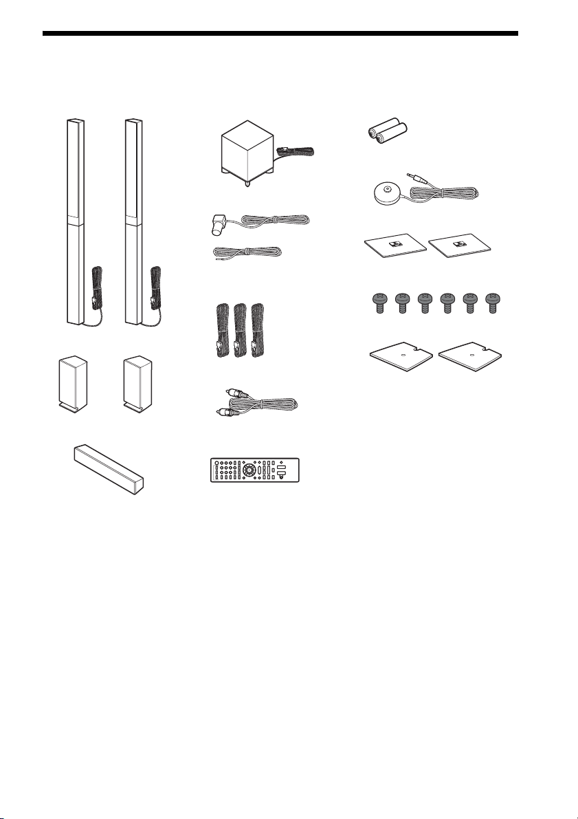
BDV-E870
• Front speakers (2)
• Subwoofer (1)
• FM wire antenna (aerial) (1)
or
• R6 (size AA) batteries (2)
• Calibration mic (1)
• Bases (2)
• Surround speakers (2)
• Center speaker (1)
• Speaker cords (3, blue/gray/
green)
• Video cord (1)
• Remote commander
(remote) (1)
• Screws (6)
• Speaker-bottom covers (2)
• Operating Instructions
• Speaker Installation Guide
• Quick Setup Guide
• End user license agreement
• Easy Setup Disc (DVD)
US
7
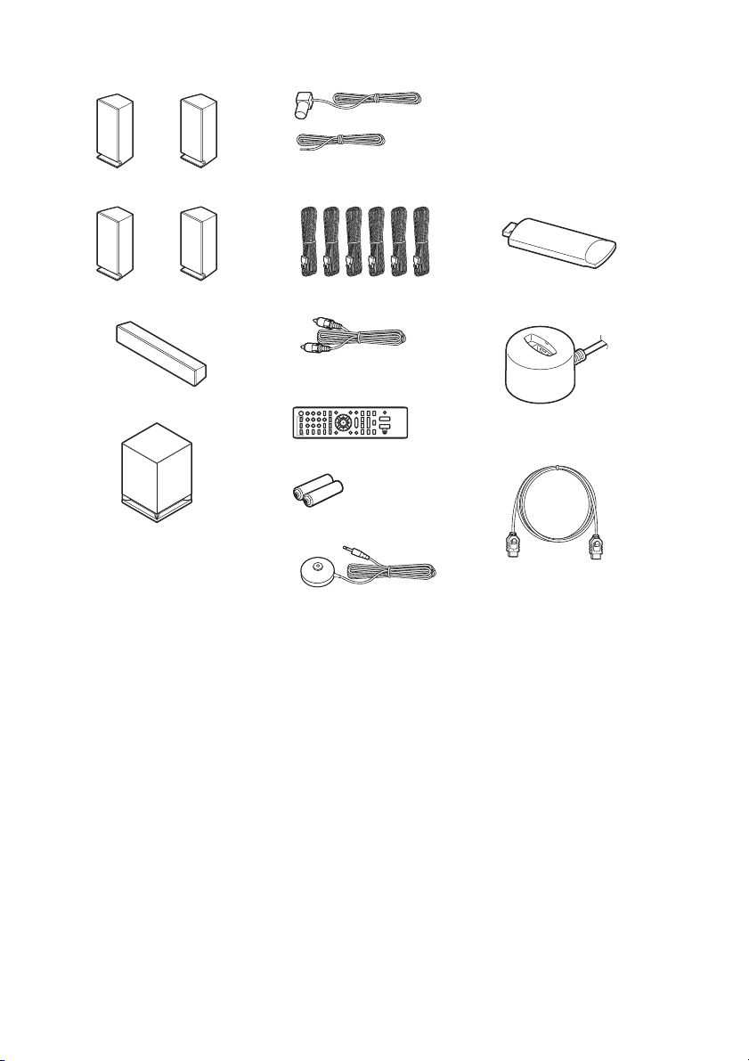
BDV-E570/BDV-E470/BDV-T57
• Front speakers (2)
• FM wire antenna (aerial) (1)
• Speaker cords (6, white/red/
• Surround speakers (2)
blue/gray/green/purple)
• Operating Instructions
• Quick Setup Guide
or
• End user license agreement
• Easy Setup Disc (DVD)
For BDV-E570/BDV-T57
• USB Wireless LAN Adapter
(UWA-BR100)
• Center speaker (1)
• Subwoofer (1)
•Video cord (1)
• Remote commander
(remote) (1)
• R6 (size AA) batteries (2)
• Calibration mic (1)
• UWA-BR100 External
cable
For BDV-T57
• HDMI cable (1)
US
8
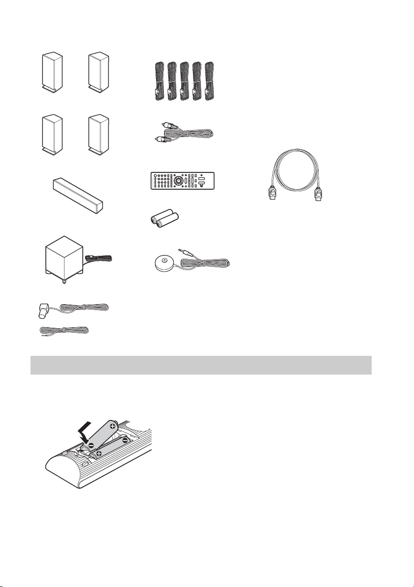
BDV-E370/BDV-T37
• Front speakers (2)
• Surround speakers (2)
• Center speaker (1)
• Subwoofer (1)
• FM wire antenna (aerial) (1)
• Speaker cords (5, white/red/
blue/gray/green)
• Video cord (1)
• Remote commander
(remote) (1)
• R6 (size AA) batteries (2)
• Calibration mic (1)
• Operating Instructions
• Quick Setup Guide
• End user license agreement
For U.S. and Canadian
models
• Easy Setup Disc (DVD)
For BDV-E370 (Latin
American models only)/BDVT37
• HDMI cable (1)
or
Preparing the remote
Insert two R6 (size AA) batteries (supplied) by matching the 3 and # ends on the batteries to the
markings inside the compartment.
US
9
Index to Parts and Control
For more information, refer to the pages indicated in parentheses.
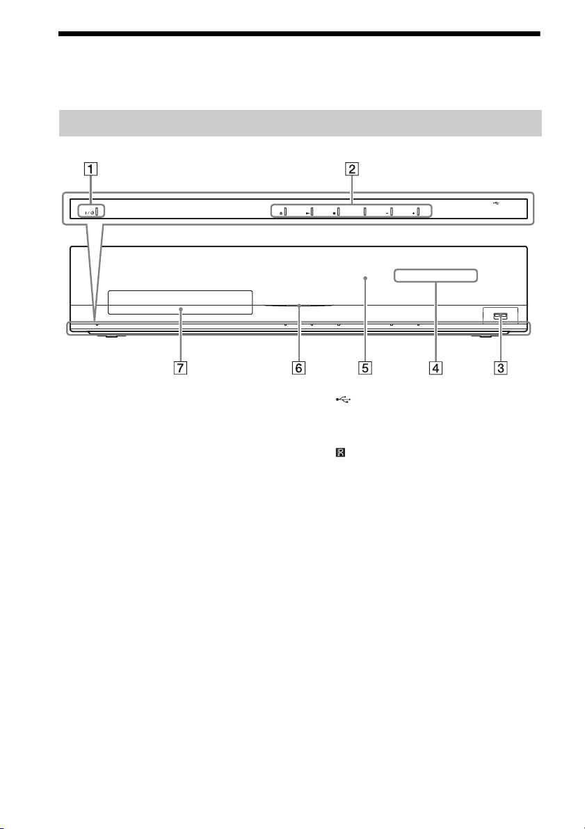
Front panel
FUNCTION VOLUME VOLUME
A "/1 (on/standby)
Turns on the unit, or sets it to standby mode.
B Play operation buttons
Z (open/close) (page 32)
Opens or closes the disc tray.
N (play)
Starts or re-starts playback (resume play).
Plays a slideshow when a disc containing
JPEG image files is inserted.
x (stop)
Stops playback and remembers the stop
point (resume point).
The resume point for a title/track is the last
point you played or the last photo for a
photo folder.
FUNCTION
Selects the playback source.
VOLUME +/–
Adjusts the system’s volume.
US
10
C (USB) port (page 33)
Used for connecting a USB device.
D Front panel display
E (remote sensor)
F Power indicator
Lights up while the system is turned on.
G Disc tray (page 32)
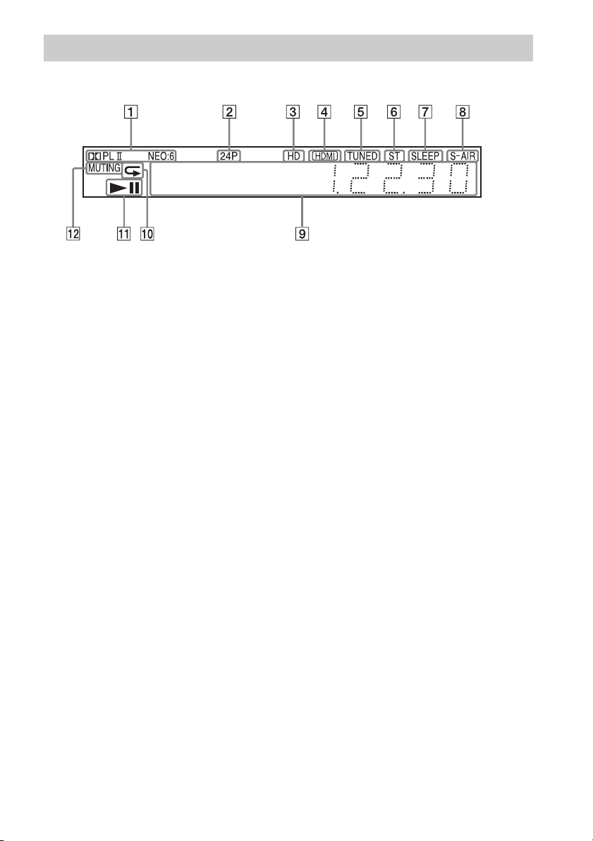
Front panel display
About the indications in the front panel display
A Displays the current sound format.
B Lights up when outputting 1920 ×
1080p/24 Hz video signals.
C Lights up when outputting 720p/1080i/
1080p video signals from the HDMI
OUT jack or 720p/1080i video signals
from the COMPONENT VIDEO OUT
jacks.
D Lights up when the HDMI OUT jack is
correctly connected to an HDCP (Highbandwidth Digital Content Protection)compliant device with HDMI or DVI
(Digital Visual Interface) input.
E Lights up when a station is received.
(Radio only) (page 40)
F Lights up when stereo sound is
received. (Radio only) (page 40)
G Flashes when the sleep timer is set.
(page 52)
H S-AIR indicator (only when the wireless
transmitter (not supplied) is inserted
into the unit)
Lights up during wireless
transmission. Flashes when [Standby]
is set to [On] and the system is in
standby mode while wireless
transmission between the unit and
S-AIR receiver is not activated. (page
42)
I Displays system’s status such as
chapter, title, or track number, time
information, radio frequency, playing
status, surround setting, etc.
J Lights up when repeat play is
activated.
K Displays system’s playing status.
L Lights up when muting is on.
11
US
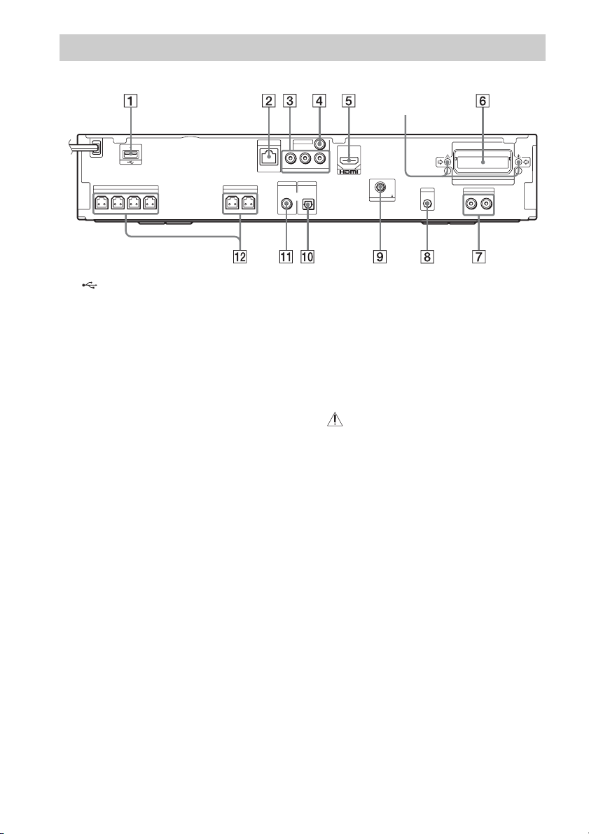
Rear panel
SPEAKERS
FRONT R
FRONT L
SUBWOOFER CENTER
SPEAKERS
SUR R SUR L
LAN(100)
Y
COMPONENT VIDEO OUT
SAT/CABLE
DIGITAL IN
COAXIAL
VIDEO OUT
PB / CBPR / C
DIGITAL IN
TV
OPTICAL
Screws*
ARC
R
OUT
FM
COAXIAL
ANTENNA
A. CAL MIC
ECM-AC2
75
EZW-T100
AUDIO
AUDIO INRL
A (USB) port (page 33)
B LAN (100) terminal (page 27)
C COMPONENT VIDEO OUT jacks (page
23)
D VIDEO OUT jack (page 23)
E HDMI OUT jack (page 23)
F EZW-T100 slot (page 42)
G AUDIO (AUDIO IN L/R) jacks (page 25)
H A.CAL MIC jack (pages 28, 49)
I ANTENNA (FM COAXIAL 75Ω) jack
(page 26)
J TV (DIGITAL IN OPTICAL) jack (page
24)
K SAT/CABLE (DIGITAL IN COAXIAL)
jack (page 25)
L SPEAKERS jacks (page 22)
* CAUTION
Please do not remove the screws unless you
are installing the EZW-T100.
12
US
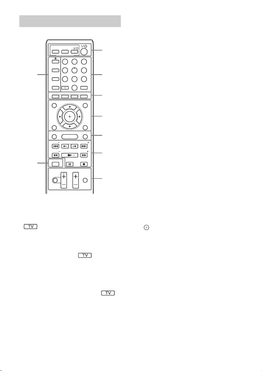
Remote control
ONE-TOUCH
TV
PLAY
THEATER
BRAVIA Sync
231
564
8097
AUDIO SUBTITLE
D.TUNING
GREENREDBLUE
POP UP/ MENU
SOUND MODE
HOME
REPLAY ADVANCE
VOL
PLAY
PAUSE
PRESET
TUNING
STOP
TV VOL
TV INPUT
9
FAVORITES
TOP MENU
RETURN OPTIONS
FUNCTION
PRESET
TUNING
8
MUTING
SLEEP
SYSTEM
MENU
YELLOW
DISPLAY
Number 5, AUDIO, VOL +, and N buttons
have a tactile dot. Use the tactile dot as a
reference when operating the remote.
• : For TV operations
(For details, see “Controlling Your TV with
the Supplied Remote” (page 52).)
A THEATER (page 48)
Switches to the optimum video mode for
watching movies automatically.
ONE-TOUCH PLAY (page 48)
Activates One-Touch Play.
TV "/1 (on/standby) (page 52)
Turns on the TV or sets it to standby mode.
"/1 (on/standby) (pages 28, 40)
Turns on the system or sets it to standby
mode.
1
2
3
4
5
6
7
B Number buttons (pages 41, 52)
Enters the title/chapter numbers, radio
frequencies, etc.
AUDIO (pages 37, 38)
Selects the audio format/track.
SUBTITLE (page 56)
Selects the subtitle language when
multilingual subtitles are recorded on a BDROM/DVD VIDEO.
D.TUNING (page 40)
Selects the radio frequencies.
C Color buttons (YELLOW/BLUE/RED/
GREEN)
Short cut keys for selecting items on some
BD menus (can also be used for Java
interactive operations on BDs).
D TOP MENU
Opens or closes the BD’s or DVD’s Top
Menu.
POP UP/MENU
Opens or closes the BD-ROM’s Pop-up
Menu, or the DVD’s menu.
OPTIONS (page 35)
Displays the options menu on the TV
screen.
RETURN
Returns to the previous display.
C/X/x/c
Moves the highlight to a displayed item.
(ENTER)
Enters the selected item.
E FUNCTION (pages 29, 40)
Selects the playback source.
HOME (pages 28, 40, 42, 49, 50, 54)
Enters or exits the system’s home menu.
SOUND MODE (page 37)
Selects the sound mode.
13
US

F Playback operation buttons
See “Playback” (page 32).
./> (previous/next)
Skip to the previous/next chapter, track, or
file.
(replay/advance)
Briefly replay the current scenes for 10
seconds./Briefly fast forwards the current
scenes for 15 seconds.
m/M (fast reverse/fast forward)
Fast reverse/fast forward the disc during
playback. Each time you press the button,
search speed changes.
Activates slow-motion play when pressed
for more than one second in pause mode.
Plays one frame at a time when pressed in
pause mode.
N (play)
Starts or re-starts playback (resume play).
Plays a slideshow when a disc containing
JPEG image files is inserted.
X (pause)
Pauses or re-starts playback.
x (stop)
Stops playback and remembers the stop
point (resume point). The resume point for
a title/track is the last point you played or
the last photo for a photo folder.
H DISPLAY (pages 32, 34)
Displays the playback information on the
TV screen.
When the function is “TV” or “SAT/
CABLE” and digital signals are input via
the DIGITAL IN jack, displays the stream
information in the front panel display.
I Z (open/close)
Opens or closes the disc tray.
SLEEP (page 52)
Sets the sleep timer.
SYSTEM MENU (pages 30, 36, 38, 40)
Enters the system menu.
FAVORITES
Displays the Internet contents added to the
Favorites List. You can save 18 favorite
Internet contents.
14
US
Radio operation buttons
See “Tuner” (page 40).
PRESET +/–
TUNING +/–
G MUTING
Turns off the sound temporarily.
VOL +/– (page 40)
Adjusts the volume.
TV VOL +/–
Adjusts the TV volume.
TV INPUT
Switches the TV’s input source between the
TV and other input sources.
Getting Started
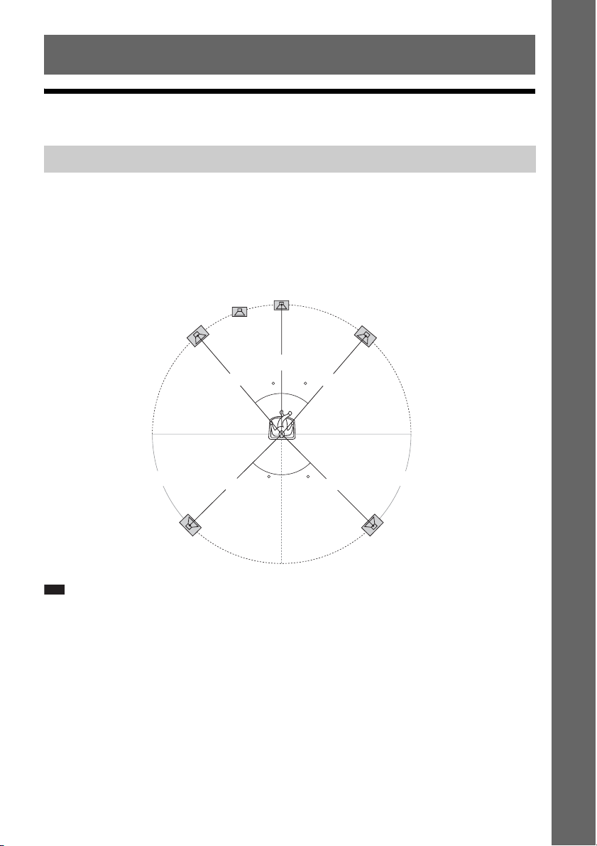
Step 1: Installing the System
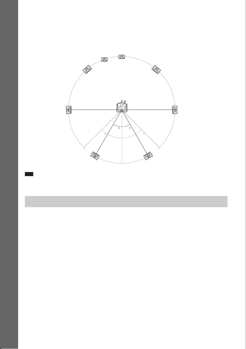
Positioning the speakers
For the best possible surround sound, place all speakers at the same distance from the listening position
(A). The distance can be between 0 to 23 feet (0.0 to 7.0 meters).
If you cannot place the center speaker and surround speakers at the same distance as (A), place them
within 23 feet (7.0 meters) of the listening position.
Place the surround speakers to the rear of the listening position (B).
The subwoofer can be placed anywhere in the room.
Subwoofer
Center speaker
Getting Started
Front left speaker (L)
Front right speaker (R)
A
A
30 30
B B
Surround left speaker (L)
Note
• Use caution when placing the speakers and/or speaker stands attached to the speakers on a specially treated (waxed,
oiled, polished, etc.) floor, as staining or discoloration may result.
• Do not lean or hang on a speaker, as it may fall down.
45
A
45
AA
Surround right speaker (R)
15
US
To add the optional surround back speakers
You can enjoy 7.1 surround sound by purchasing the Wireless Surround Speaker Kit (WAHT-SBP2,
optional). The optional product lineup differs depending on the area.
For the position of the surround back speakers, refer the illustration below (C).
Subwoofer
Center speaker
Getting Started
Note
• To use the surround back speakers, set [Surround Back] (page 50) in [Speaker Settings] to [Yes] while performing
the Easy Setup (page 28).
Front left speaker (L)
Surround left
speaker (L)
Surround back left speaker (L)
(optional)
30 30
45 45
CC
Front right speaker (R)
Surround right
speaker (R)
Surround back right speaker (R)
(optional)
Installing the speakers on a wall
Caution
• Contact a screw shop or installer regarding the wall material or screws to be used.
• Use screws that are suitable for the wall material and strength. As a plaster board wall is especially fragile, attach
the screws securely to a beam and fasten them to the wall. Install the speakers on a vertical and flat wall where
reinforcement is applied.
• Sony is not responsible for accidents or damage caused by improper installation, insufficient wall strength or
improper screw installation, natural calamity, etc.
Before installing the front speakers of BDV-E870 on a wall, you need to disassemble the speakers. You
can install the upper part of the speakers on a wall.
US
16
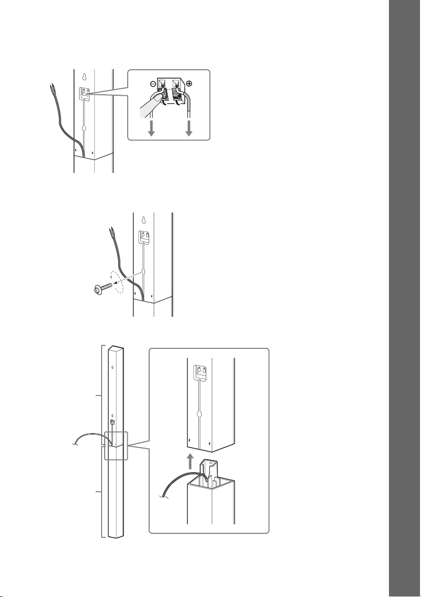
To disassemble the speaker
(Front speakers of BDV-E870 only)
1 Disconnect the speaker cords from the speaker.
Rear of the speaker
2 Remove the screw (pre-installed) at the rear of the speaker.
This screw is used when reassembling the speaker. Be sure not to lose the screw.
Getting Started
Screw
Rear of the speaker
3 Disassemble the speaker by lifting the upper part of the speaker.
Upper part
Lower part
Rear of the speaker
17
US
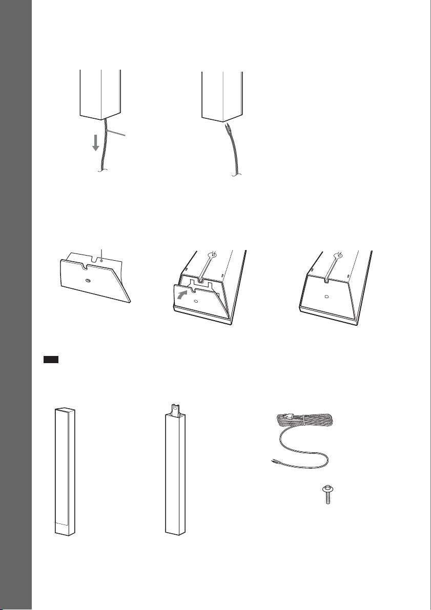
4 Pull out the speaker cord from the bottom of the lower part of the speaker.
The removed speaker cord is used when installing the speaker on a wall.
Lower part of the speaker
,
Getting Started
Speaker cord
5 Remove the protection paper from the speaker-bottom cover, then attach the speaker-
bottom cover to the bottom of the upper part of the speaker.
Bottom of the upper part of
Protection paper
the speaker
,,
Speaker-bottom cover
Note
• When removing the protection paper, pull it off via the section exposed by the notch in the speaker-bottom cover.
Fully-disassembled illustration
18
Upper part of
the speaker
US
Lower part of
the speaker
Speaker cord
Screw
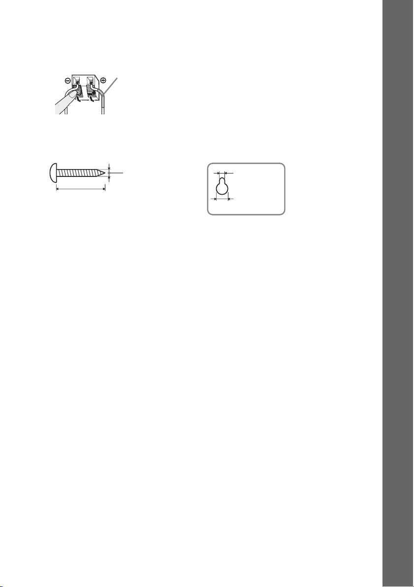
To install the speakers on a wall
Before installing the speakers on a wall, connect the speaker cord to the speaker.
Be sure to match the speaker cords to the appropriate terminals on the speakers: the speaker cord with
the color tube to 3, and the speaker cord without the color tube to #.
Color tube
Front left speaker (L): White
Front right speaker (R): Red
Center speaker: Green
Surround left speaker (L): Blue
Surround right speaker (R): Gray
1 Prepare screws (not supplied) that are suitable for the hole on the back of each speaker.
See the illustrations below.
Getting Started
30 mm (1 3/16 inches)
4 mm (
3
/16 inch)
5 mm
7
/32 inch)
(
10 mm
13
(
/32 inch)
Hole on the back of
the speaker
19
US
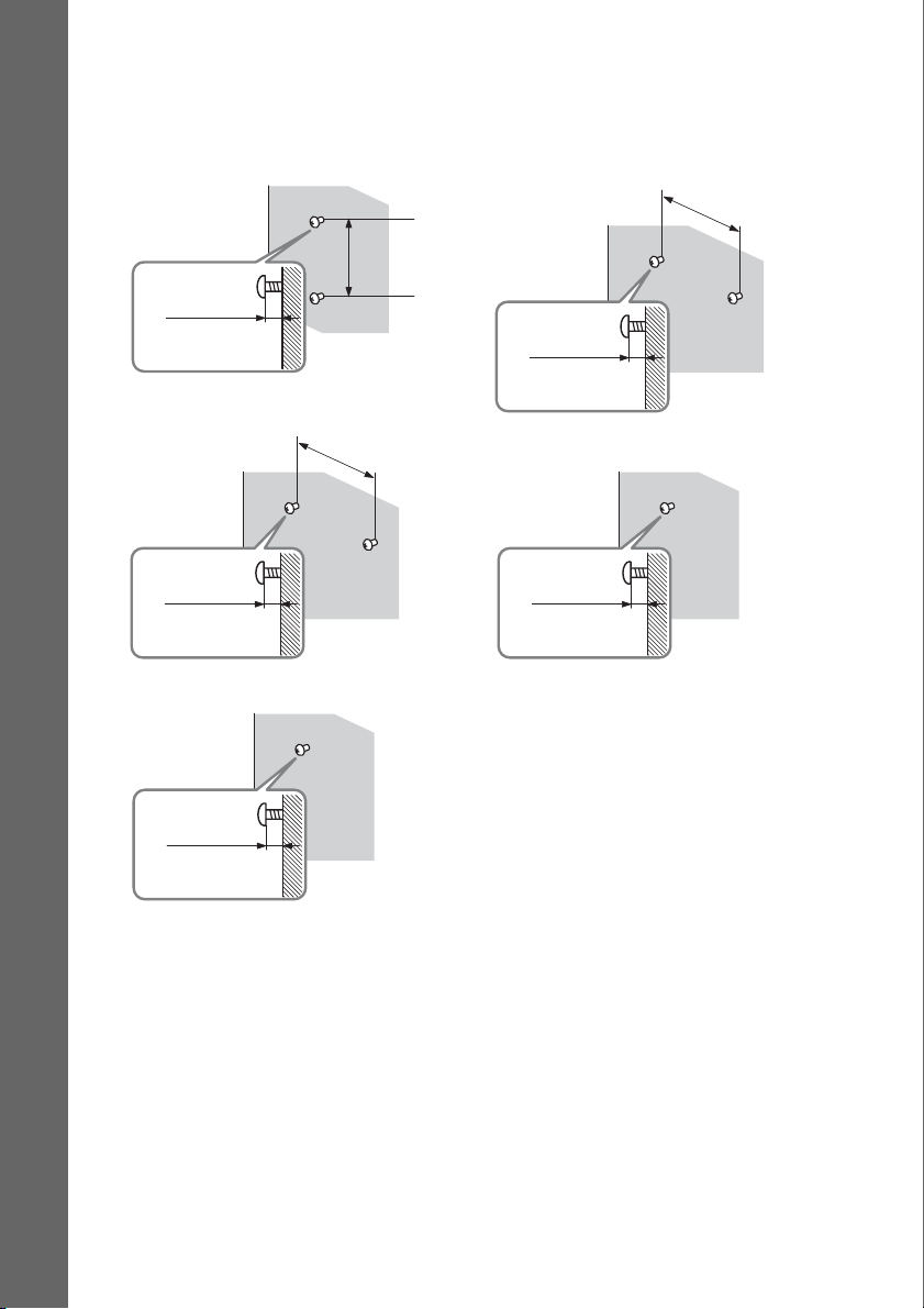
2 Fasten the screws to the wall.
Getting Started
BDV-E870
For the front speakers
8 to 10 mm
11
/32 to 13/32
(
For the center speaker
11
(
/32 to 13/32
For the surround speakers
inch
8 to 10 mm
inch
)
)
304 mm
12
inches)
(
219 mm
(
8 5/8 inches)
BDV-E570/BDV-E470/BDVE370/BDV-T57/BDV-T37
For the center speaker
219 mm
8 5/8 inches)
(
8 to 10 mm
11
(
/32 to 13/32
For the other speakers
11
(
/32 to 13/32
inch
8 to 10 mm
inch
)
)
20
8 to 10 mm
11
(
/32 to 13/32
US
inch
)
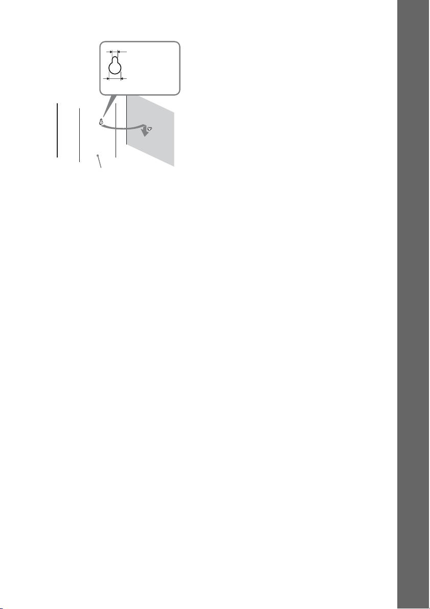
3 Hang the speakers on the screws.
5 mm
7
(
/32 inch)
10 mm
13
/32 inch)
(
Rear of the speaker
Hole on the back of
the speaker
Getting Started
21
US
Step 2: Connecting the System
For connecting the system, read the information on the following pages.
Do not connect the AC power cord (mains lead) of the unit to a wall outlet (mains) until all the other
connections are made.
Note
• When you connect another component with a volume control, turn down the volume of the other components to a
Getting Started
level where sound is not distorted.
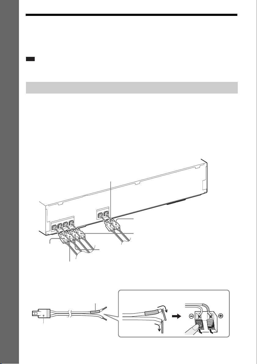
Connecting the speakers
The connector of the speaker cords and the color tube are color-coded depending on the type of speaker.
Connect the speaker cords to match the color of the SPEAKERS jacks of the unit.
Be sure to match the speaker cords to the appropriate terminals on the speakers: the speaker cord with
the color tube to 3, and the speaker cord without the color tube to #. Do not catch the speaker cord
insulation (rubber covering) in the speaker terminals.
To connect speaker cords to the unit
When connecting to the unit, insert the connector until it clicks.
Rear panel of the unit
Gray
(Surround right speaker (R))
S
R
E
K
A
E
P
S
L
O
R
F
Red
(Front right
speaker (R))
S
R
E
K
A
E
P
S
R
E
T
N
E
C
R
FE
O
O
W
B
U
S
L
T
N
O
R
F
R
T
N
White
(Front left speaker (L))
R
U
S
R
R
U
S
Purple
(Subwoofer)
Blue
(Surround left speaker (L))
Green
(Center speaker)
To connect speaker cords to the speaker
Connector
US
22
Color tube
(+)
(–)
Rear or bottom of the speaker
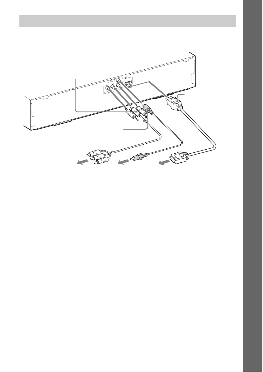
Connecting the TV (Video connection)
This connection sends a video signal to the TV.
Depending on the jacks on your TV, select the connection method.
Rear panel of the unit
B Component video
cable (not supplied)
C Video cord (supplied)
T
U
O
O
E
ID
V
ARC
OUT
R
/ C
R
P
B
/ C
T
B
P
U
O
O
E
ID
V
Y
T
N
E
N
O
P
M
O
C
Getting Started
A HDMI cable*
To the component
video input jacks of
the TV.
To the video input
jack of the TV.
To the HDMI IN jack
of the TV.
* The HDMI cable is supplied with BDV-E370 (Latin American models), BDV-T57, and BDV-T37 only.
Method 1: HDMI cable (A) connection
If your TV has an HDMI jack, connect to the TV with an HDMI cable. Picture quality will be improved
compared to using the component video cable connection or the video cord connection.
When connecting with the HDMI cable, you need to select the type of output signal (page 55).
Method 2: Component video cable (B) connection
If your TV does not have an HDMI jack, but has component video input jacks, connect to the TV with
a component video cable. Picture quality will be improved compared to using the video cord
connection.
When connecting with the component video cable, you need to select the type of output signal (page
55).
Method 3: Video cord (C) connection
If you do not have an HDMI cable or a component video cable, temporarily make this connection.
23
US
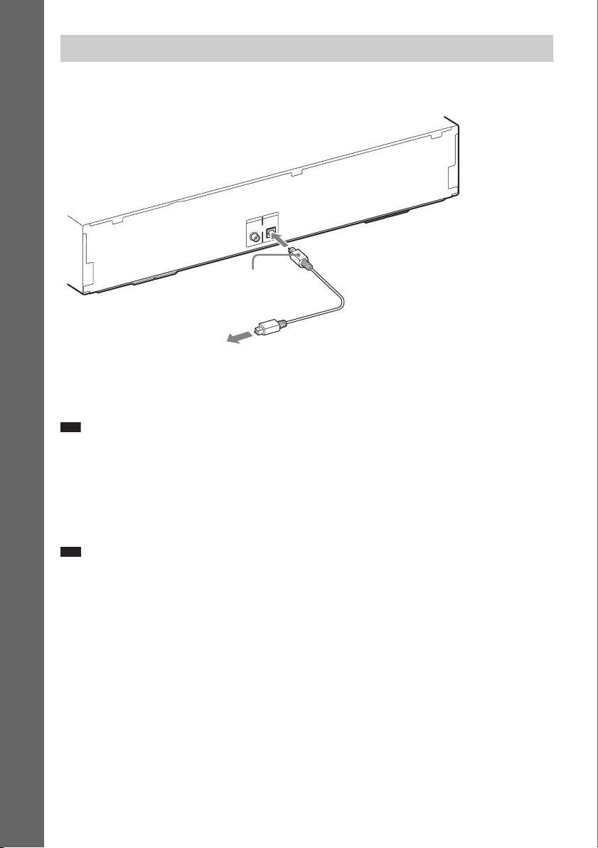
Connecting the TV (Audio connection)
This connection sends an audio signal to the unit from the TV. To listen to TV sound via the system,
perform this connection.
Rear panel of the unit
Getting Started
IO
D
AU
IN
IO
D
U
A
V
T
E
N
I
L
L
B
A
A
T
I
/C
G
T
I
A
D
S
N
I
L
A
T
I
G
I
D
L
A
C
I
T
P
O
L
A
I
X
A
O
C
Digital optical cord (not
supplied)
To the digital optical out jack of
the TV.
With a digital audio connection, the system receives a Dolby Digital multiplex broadcast signal and
you can enjoy multiplex broadcast sound.
Note
• When you connect the TV and the unit with an audio cord, see “Connecting the other components” (page 25).
RL
About Audio Return Channel
If your TV is compatible with the Audio Return Channel function, an HDMI cable connection also
sends a digital audio signal from the TV. You do not need to make a separate audio connection for
listening to TV sound. For details of the Audio Return Channel function, see [Audio Return Channel]
(page 58).
Note
• A digital optical cable connection has priority over the Audio Return Channel function via HDMI cable connection.
US
24
 Loading...