

Page 1

Operator Manual
Guide de lopérateur
Betriebsanleitung
Manual del operador
SB-80
SB-80
SERIAL NO. 1000 TO CURRENT
WARNING
All personnel shall carefully read, understand and follow all safety rules,
and operating instructions before performing maintenance on or
operating any UpRight aerial work platform.
Refer to page 2 for the English language version of this Operator Manual.
Safety Rules and Operating Instructions
AVERTISSEMENT
Tout le personnel doit lire attentivement et respecter toutes les
consignes de
Reportez-vous à la page 13 pour la version française de ce guide de lopérateur.
WARNUNG
Alle Bediener müssen die Sicherheitsregeln und Bedienungsanleitungen
gründlich durchlesen, verstehen und befolgen, bevor sie an irgendeiner UpRight-
Hocharbeitsbühne Wartungsarbeiten ausführen oder diese in Betrieb nehmen.
Bezüglich der deutschsprachigen Ausgabe dieser Betriebsanleitung siehe Seite 24.
ADVERTENCIA
Todo el personal debe leer atentamente, entender y respetar todas las
reglas de seguridad, las instrucciones de operación antes de efectuar
trabajos de mantenimiento o manejar cualquier plataforma aérea de
Referirse a la página 35 para la versión en español de este manual del operador.
Safety Rules and Operating Instructions
1
Page 2
English Language Section
SAFETY RULES
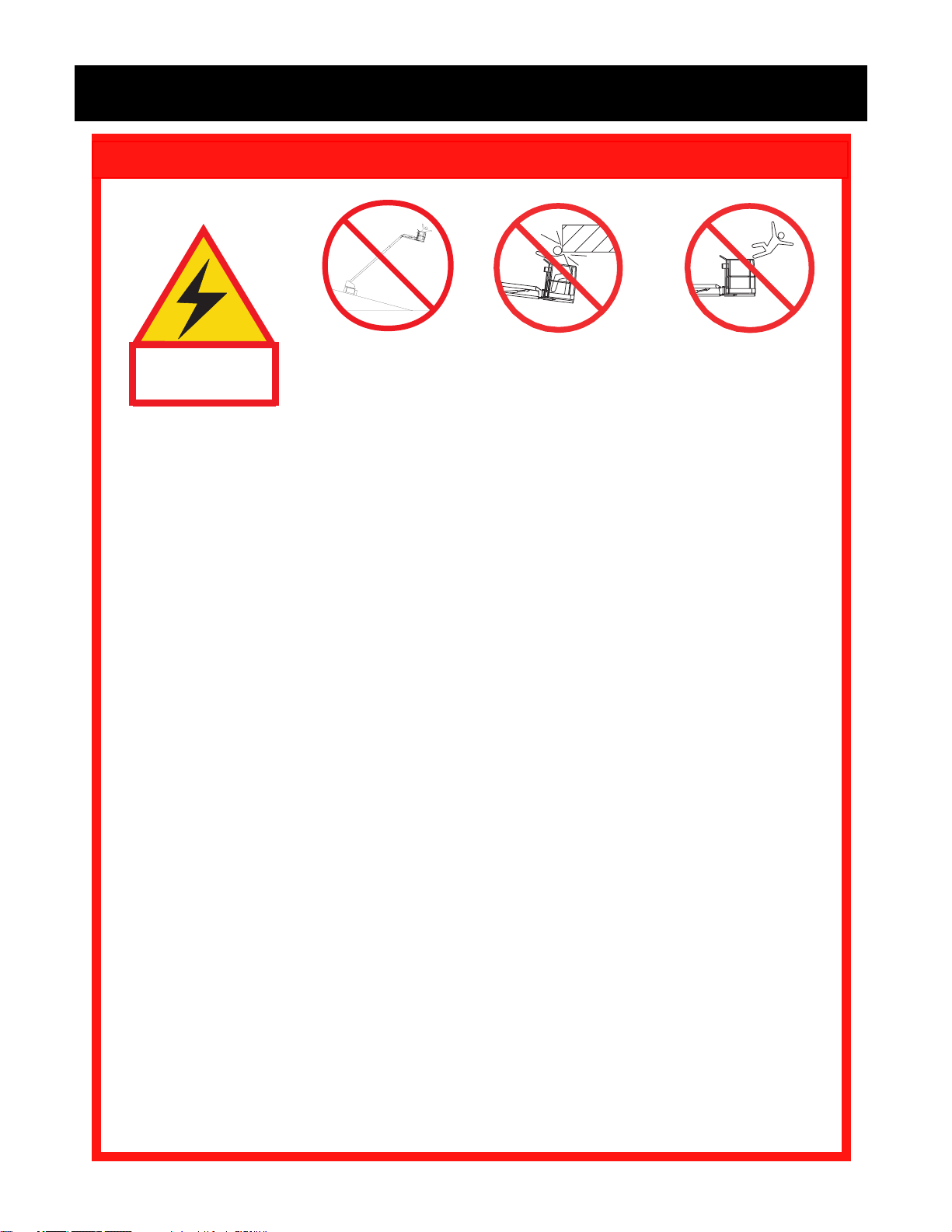
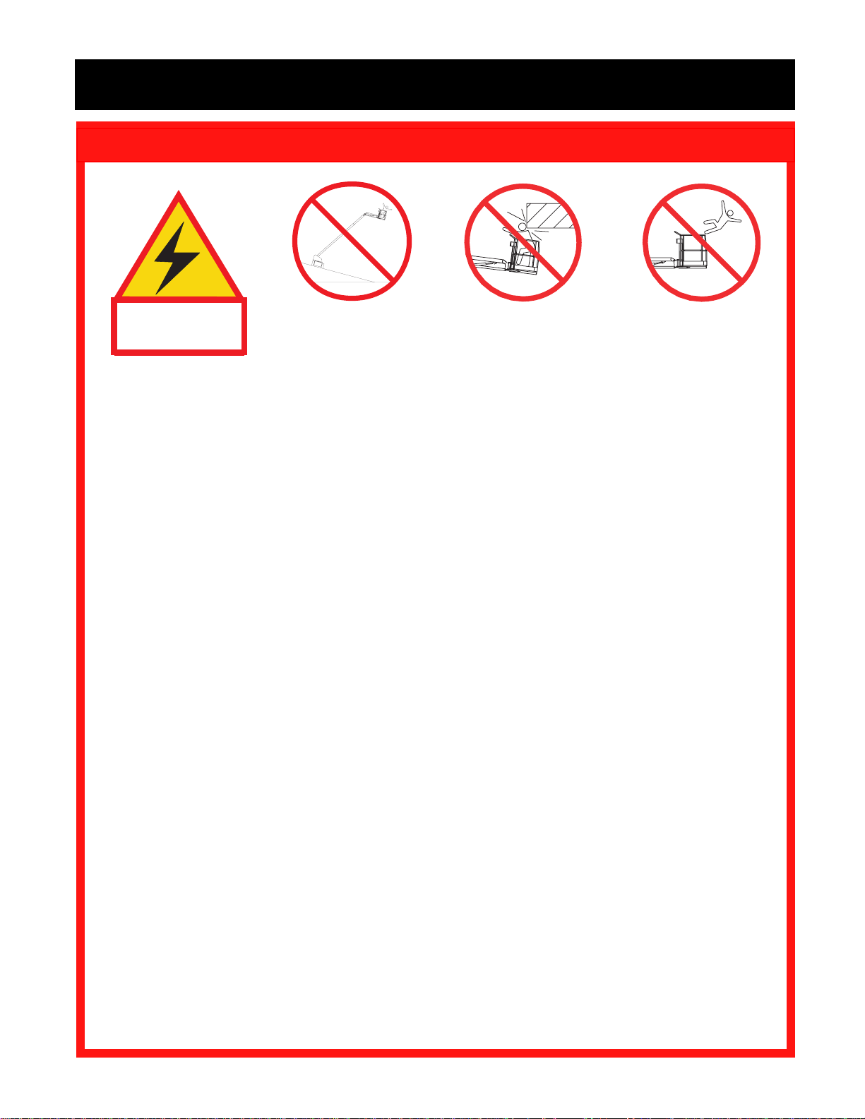
Tip Over HazardElectrocution
Hazard
Collision Hazard
Fall Hazard
THIS MACHINE IS
NOT INSULATED.
USE OF THE AERIAL WORK PLATFORM: This aerial work platform is intended to lift persons and his tools as well as
the material used for the job. It IS designed for repair and assembly jobs and assignments at overhead workplaces
(ceilings, cranes, roof structures, buildings etc.). All other uses of the aerial work platform are prohibited!
THIS AERIAL WORK PLATFORM IS NOT INSULATED! For this reason it is imperative to keep a safe distance from
live parts of electrical equipment!
ALL occupants must wear an approved fall restraint properly attached to designated platform anchorage point. Attach
only one fall restraint to each anchorage point.
Exceeding the specified permissible maximum load of 272 kg (600 lbs.) including (2) persons on the platform is
prohibited!
The use and operation of the aerial work platform as a lifting tool or a crane (lifting of loads from below upwards or from
up high on down) is prohibited!
NEVER exceed 45 lbs. (200 N) of side force per occupant.
DISTRIBUTE all platform loads evenly on the platform.
NEVER operate the machine without first surveying the work area for surface hazards such as holes, drop-offs, bumps,
curbs, or debris; and avoiding them.
OPERATE machine only on surfaces capable of supporting wheel loads.
NEVER operate the machine when wind speeds exceed 28 mph (12.5 m/sec.= Beaufort scale 6).
IN CASE OF EMERGENCY push emergency stop button to deactivate all powered functions.
Climbing up the railing of the platform, standing on or stepping from the platform onto buildings, steel or prefab concrete
structures, etc., is prohibited!
Dismantling the swing gate or the liftable bar or other railing components is prohibited! Always make certain that the
swing gate or the liftable bar is closed and securely locked! It is prohibited to keep the swing gate or the liftable bar in
an open position (e.g. held open with tie-straps) when the platform is raised!
To extend the height or the range by placing of ladders, scaffolds or similar devices on the platform is prohibited!
INSPECT the machine thoroughly for cracked welds, loose or missing hardware, hydraulic leaks, loose wire connections,
and damaged cables or hoses before using.
VERIFY that all labels are in place and legible before using.
NEVER use a machine that is damaged, not functioning properly, or has damaged or missing labels.
IF ALARM SOUNDS while boom is elevated, STOP, carefully retract boom and lower platform without rotating. Move
machine to a firm, level surface.
To bypass any safety equipment is prohibited and presents a danger for the persons on the aerial work platform and in
its working range.
NEVER charge batteries near sparks or open flame. Charging batteries emit explosive hydrogen gas.
Modifications to the aerial work platform are prohibited or permissible only at the approval by UpRight.
The attachment or use of components not manufactured or supplied by UpRight is prohibited!
NEVER tow the machine. Transport by truck or trailer only.
AFTER USE, secure the work platform from unauthorized use by turning both keyswitches off and removing key.
NEVER operate the
boom or drive with
platform elevated
unless on firm level
surface.
NEVER position the
platform without first
checking for overhead
obstructions or other
hazards.
NEVER climb, stand or
sit on platform guardrails
or midrail.
2
Page 3

Introduction
This manual covers the operation of internal combustion
powered models of the SB-80 Boom. This manual must
be stored on the machine at all times.
Pre-Operation and Safety
Inspection
Carefully read, understand and follow all safety
rules, labels, and operating instructions, then
perform the following steps each day before use.
Perform a complete visual inspection of the entire unit
prior to operating. Check the following areas for discrepancies:
1. Open panels and check hydraulic components / hoses
for damage or leaks. Check electrical components /
wiring for damage or loose connections.
2. Inspect chassis, axles, hubs, and steering linkage
for damage, deformation, buckled paint, loose or
missing hardware, and cracked welds.
3. Check tires for damage, punctures, and inflation; tire
pressure must be 7 bar (100 psi).
4. Check all hoses / cables for wear.
5. Inspect elevating assembly for damage, deformation, buckled paint, loose or missing hardware, and
cracked welds.
6. Inspect platform and guardrails for damage, deformation, buckled paint, loose or missing hardware,
and cracked welds. Insure that gate operates freely.
7. Check Hydraulic fluid level with platform fully lowered.
8. Check fluid level in batteries (see Battery mainte-
nance, page 10).
9. Check fuel level, add fuel if necessary (see Fueling,
page 10).
10. Check engine oil level.
NEVER remove the cap from a hot radiator. Hot
coolant can cause severe burns
11. Ensure that radiator is cold, check coolant level. Add
if necessary.
.
SYSTEM FUNCTION INSPECTION
Note: Refer to Figures 1 through 5 for chassis and
platform control locations.
IMPORTANT: Before performing the System Function Inspection be sure the axles are fully extended.
For axle extending instructions, refer to "Extending
and retracting Axles" (Page 6).
1. Before performing the following tests, check area
around machine and overhead for obstructions,
holes, drop-offs, and debris.
2. Turn chassis key switch to chassis, and pull out
emergency stop switches at the chassis control
panel and at the platform control panel.
3. Retract locking bolt. See Figure 1.
4. Press the engine start button to crank the engine;
release when engine starts.
5. Push in the chassis emergency stop button, engine
should stop. Repeat for platform emergency stop
button. Return both emergency stop buttons to the
on position, and start engine.
6. With axles fully extended, operate each function
switch to raise / lower, extend/retract, rotate left/
right, each section of the elevating assembly and
observe the operation of the machine. All functions
should operate through full cycle smoothly.
7. Turn chassis key switch to platform.
8. Mount the platform, and (If required by National
Legislation) attach approved fall restraint to designated platform anchorage point. Attach only one fall
restraint to each point.
9. While engaging the hand interlock, move the drive
control handle forward and reverse. Observe that
proportional functions operate smoothly, and that
brakes apply quickly after control is released.
10. While engaging the hand interlock, operate steer
switch to left and right. Observe that steering wheels
turn properly.
11. While depressing foot switch, operate boom controls. Observe that boom operates smoothly, and
that boom raise and lower, turret rotation, and boom
extension and retraction operate proportionally in
conjunction with stroke of handle. Observe that
platform maintains level when boom is elevated.
3
Page 4

NOTE: Boom will not extend or raise beyond 45
degrees unless axles are fully extended.
Controls and Indicators
12. With the boom elevated five degrees or greater or
extended 0,3 m (1 foot), operate drive control
handle. Observe that drive speed is limited to creep
(0,3 m [1 foot] per second). Lower upper boom to
stowed position.
13. Press the service horn button. Observe that horn is
audible.
NOTE: Hand interlock controls drive/steer and boom
rotate functions only.
NOTE: Foot switch controls boom functions only.
14. Level the platform while it is in the stowed position.
DO NOT use a machine that is damaged or
malfunctioning. Tag and remove the unit from
service until it is repaired.
1
2
3
5
4
9
8
12
13
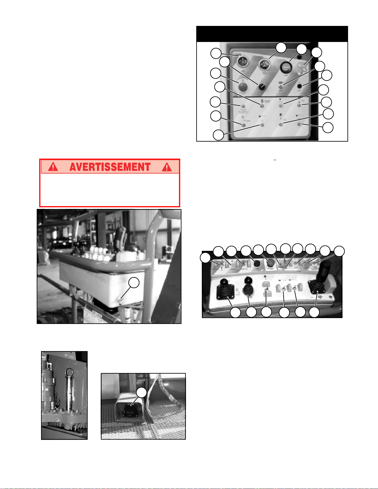
Figure 4: Chassis Controls
1. Oil pressure gauge
2. Water temperature gauge
3. Hourmeter
4. Emergency stop
5. Key switch
6. Engine start
7. Glow plug (Diesel only)
8. Auxiliary power for emergency lowering only
9. Function enable
10. Boom control
11. Boom extension control
12. Turret control
13. Jib control
14. Cage rotation
15. Cage level control
16. Circuit breaker
24
23
22
21
18 19
20
17
25
16
6
10
26
7
11
14
15
27
Figure 1: Platform Controls
Figure 2: Locking pin
34
35
Figure 3: Foot Switch
29
28
Figure 5: Platform Controls
17. Axle Extend/Retract
18. Lights (optional)
19. Generator (optional)
20. Horn Button
21. Emergency stop
22. Axles Extended indicator
23. Tilt warning indicator
24. Low oil pressure indicator
25. Torque/Speed selector
26. Glow plug (Diesel only)
27. Auxiliary power for emergency lowering only
28. Boom Raise/Lower and Turret Rotate control
29. Boom Extend/Retract
30. Cage Rotate
31. Jib Raise/Lower
32. Cage Level
33. Drive control handle/interlock
34. Engine start
35. Foot interlock switch
30 31
32
33
4
Page 5
Operation
Before operating work platform insure that:
Pre-operation and safety inspection has been
completed, and any discrepancies have been
corrected.
System function inspection has been performed.
Operator has been thoroughly trained on the
operation of the machine.
Work area is clear of all obstructions, holes, drop-
offs, or persons in the route of travel.
Surface is capable of supporting wheel loads.
Refer to figures 1 through 5 for control locations.
Emergency Stop
At any time during operation, press the emergency stop
button to stop all functions in an emergency.
Starting the engine
From the lower controls
1. Turn the chassis key switch to chassis position.
2. Press the start button to crank the engine. Release
when the engine starts.
3. Diesel Engines: When the engine is cold; press and
hold the glow plug switch 6 seconds before starting
engine.
From the platform controls
1. Turn the chassis key switch to platform controls.
2. Turn the platform rotary switch fully clockwise to
crank the engine. Release when engine starts.
3. Diesel Engines: When the engine is cold; press and
hold the glow plug switch 6 seconds before starting
engine.
Driving
Service Horn
At any time during operation, press the service horn
button to sound an audible warning if necessary.
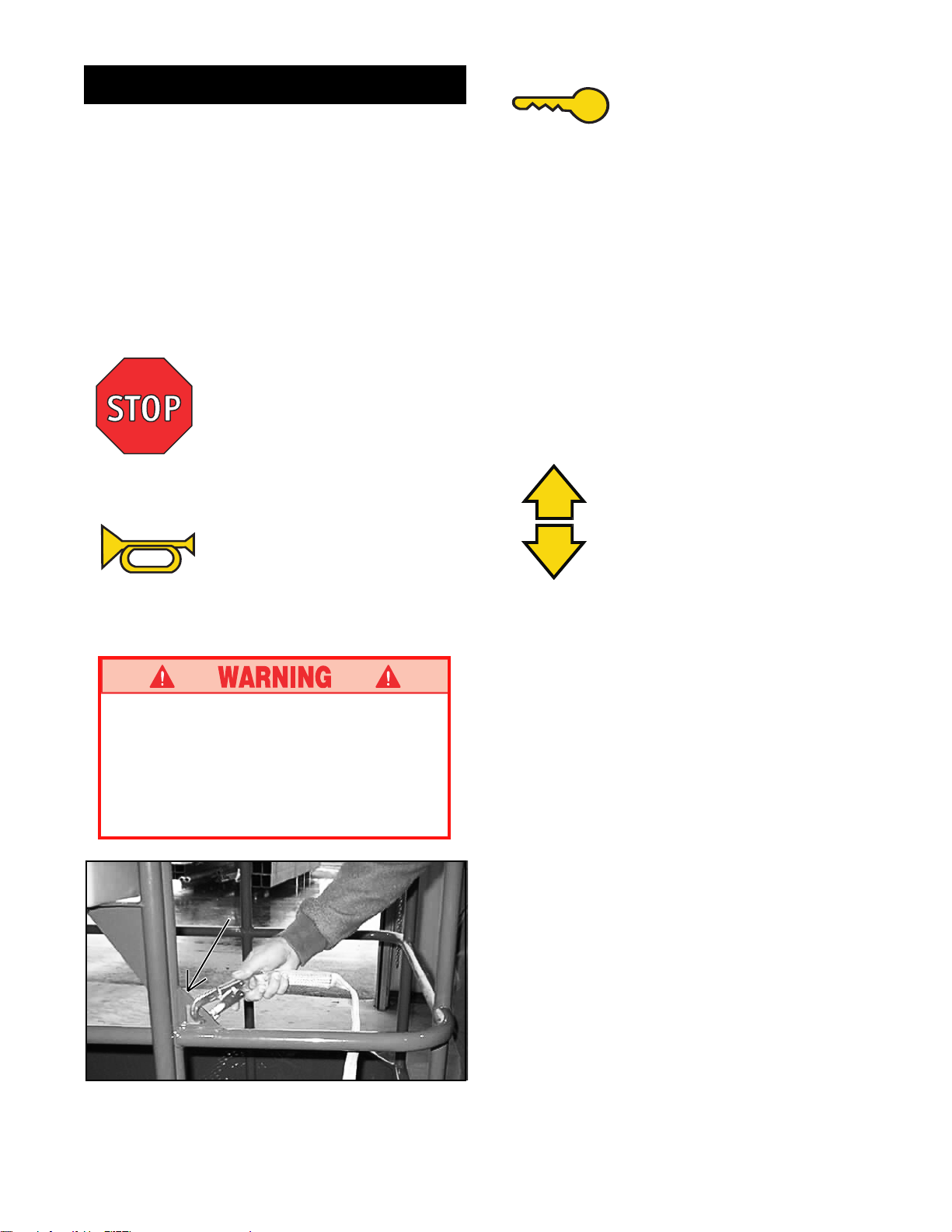
Always wear an approved fall restraint properly
attached to designated platform anchorage
point when driving or operating the machine
(see Figure 6).
Attach only one fall restraint to each anchorage
point.
With Boom Lowered
1.
Turn chassis key switch to platform, and pull out the
chassis emergency stop switch.
2. Mount the platform and close sliding rail.
3. Attach approved fall restraint (If required by National
Legislation) to designated platform anchorage point.
Attach only one fall restraint to each point.
4. Start the engine.
5. Check that the area around and above the work
platform is clear of obstructions, holes, drop-offs,
persons in the route of travel, and the surface is
capable of supporting wheel loads.
6. Engage the interlock switch and move the drive
control handle forward to travel forward and rearward to travel in the reverse direction.
Note: When the boom is rotated to the front of the
chassis (steering wheels aft) directions of travel and
steering will be reversed. Observe the color coded
arrows on the control panel near the drive control
handle, and on the chassis. They will indicate the
direction of travel when the drive control handle is
moved.
Figure 6: Typical Fall Restraint Anchorage Point
5
Page 6
Extending and
Retracting Axles
From the platform controls
IMPORTANT: Axles must be fully extended to
allow boom extension or boom raised above 450.
Machine must be driven forward or reverse while
extending the axles. Ensure all four wheels can be
clearly seen and persons and obstacles are clear
of the machine.
POSITIONING THE PLATFORM
Positioning the platform as close as possible to the
work area requires some planning. First, you must
survey the work site to find a suitable place to park
the machine. This must be a firm level area as close
as possible to the work area. Take into consideration
all obstructions on the ground and overhead and
avoid them.
Before operating any function, check the area around
and overhead for any obstructions or electrical
conductors.
1. Move and hold axle extend/retract switch to
extend or retract.
2. Drive the machine forward or reverse. The axles
will extend or retract.
3. When the axles are fully extended, the axles
extended light (green light on platform controller)
will illuminate.
NOTE: Verify Yellow bars are visible on all four
axles at full extension.
4. Re-synchronize the steering geometry by steering
full left or full right and holding for a few seconds.
5. All boom functions are now available.
With Boom Elevated
Travel with boom elevated is restricted to firm
level surfaces only.
When driving elevated, the machine will travel at
creep speed (0,3 m [1 foot] per second).
Steering
1. While engaging the hand interlock, push the
steering switch (located on top of the control
handle) to turn left or right.
Multifunction Controls
The UpRight SB-80 employs the use of multifunction
controls. This means that any three functions can
operate at full speed simultaneously.
The turret may be rotated while driving if necessary to
make turns in tight areas.
Lower Control Operation
Do not operate machine from lower controls if
someone is in the platform.
All boom functions will operate at fixed speed.
1. Turn chassis keyswitch to chassis controls.
2. With engine running, operate boom control
switches to position the platform.
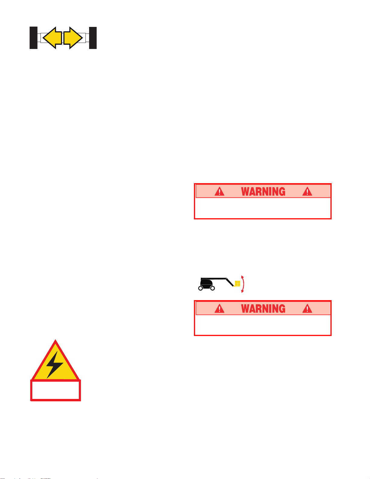
Leveling the Platform
Note: Steering is not self centering. Wheels must
be returned to the straight ahead position by
operating the steering switch.
This machine is not insulated.
Follow your national safety
standards and maintain the
required safety distance when
THIS MACHINE IS
NOT INSULATED.
working near energized equipment.
DO NOT operate the machine if the platform
does not maintain level when elevated.
While depressing the foot switch, move the
platform level control switch forward to swing the
platform upward, rearward to swing the platform
downward. Release the switch to stop leveling.
6
Page 7
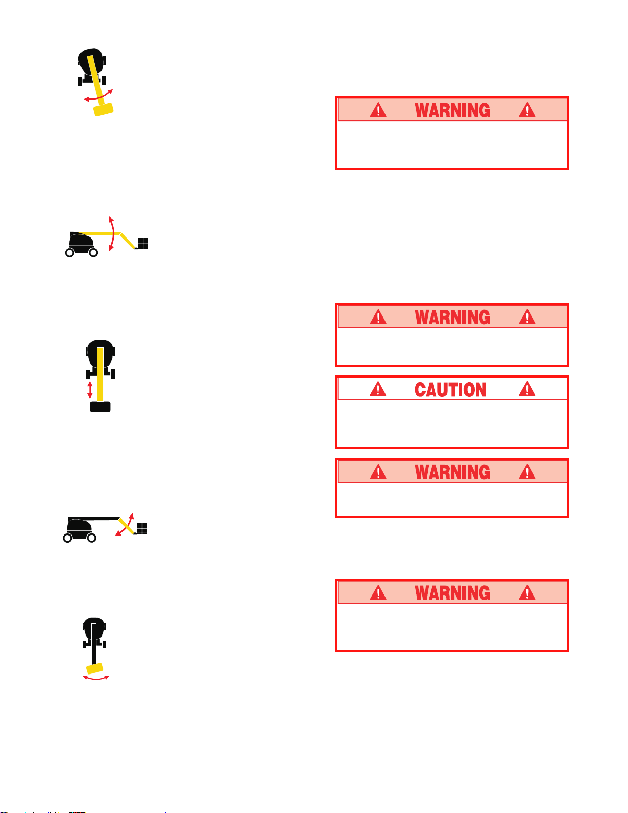
Rotating the Turret
EMERGENCY OPERATION
In the event of an engine failure, the elevating assembly
may be lowered using the following procedure.
While depressing the foot switch, move the boom
rotation joystick to the right to rotate right, left to rotate
left. Release the switch to stop rotation. The turret
rotation will function at a speed proportional to the stroke
of the joystick. Make sure the area around the boom is
clear of all obstructions before rotating the turret.
Elevating the Boom
While depressing the foot switch, move the joystick forward
to elevate the boom, rearward to lower the boom. Release
the control lever to stop elevating / lowering. The boom
elevate will function at a speed proportional to the stroke of
the joystick.
Extending the Boom
While depressing the foot switch, move the boom
extension control joystick rearward to extend the boom,
forward to retract the boom. Release the control lever to
stop extending / retracting. The boom extension will
function at a speed, proportional to the stroke of the
joystick.
NEVER climb down the elevating assembly. If
controls do not respond, follow the emergency
lowering procedure.
Lowering Elevating Assembly
1. Engage the auxiliary power unit switch.
2. Operate any boom function in the normal manner.
Note: Auxiliary battery is capable of one emergency
lowering cycle before requiring recharge. Battery is
recharged while engine is in operation.
EMERGENCY TOWING
Chock wheels before disengaging hubs.
Machine may roll.
DO NOT tow the machine faster than 5 km/h
(3 mph). Faster speeds will damage drive
components and void warranty.
Elevating the Jib
While depressing the foot switch, push the jib control
switch forward to elevate the jib, rearward to lower the jib.
Release the control lever to stop elevating / lowering.
Rotating the Platform
While depressing the foot switch, toggle the control
switch left to rotate left, right to rotate right. Release the
switch to stop rotation.
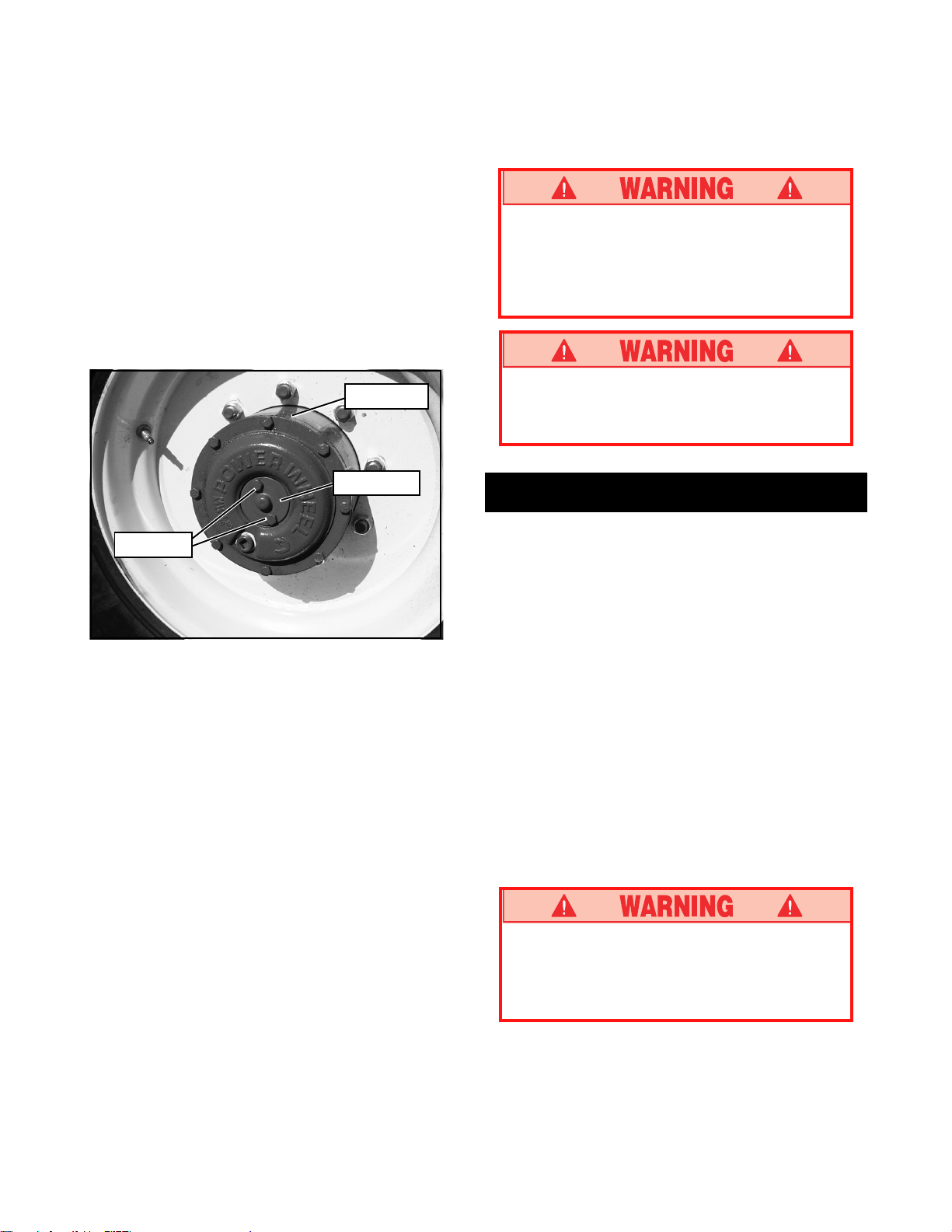
There are no brakes when the center caps are
installed in the inverted position.
Perform the following only when the machine will not
operate under its own power and it is necessary to
move the machine or when winching onto a trailer for
transportation.
DO NOT use a machine that is damaged or
malfunctioning. Tag and remove the unit from
service until it is repaired.
7
Page 8
1. Ensure that the platform is fully lowered, and that the
turret is rotated so that the platform is to the rear of
the machine.
2. Refer to figure 7 and disengage all four drive hubs.
Remove two (2) screws and center cap. Reinstall
center cap in the opposite direction.
3. Attach adequate chain/cable of sufficient strength for
towing the machine to the front or rear tie down lugs.
4. When ready to move the machine, remove the
chocks. Tow or winch into position and replace
chocks.
5. Engage all four drive hubs by returning the center
caps to their original orientation.
MACHINES EQUIPPED WITH
ELEV-8 OPTION
Machines equipped with Elev8 option are capable of
operating all functions on a firm 3 Degree slope.
Do not operate machines with Elev8 option
unless machine is equipped with foam filled
tires. Remove machine from service and install
proper tire/wheel combination before operating
machine.
Drive Hub
Center Cap
Screws
Figure 7: Drive Hub
(Operating position shown)
AFTER USE EACH DAY
1. Ensure that the platform is fully lowered.
2. Park the machine on level ground, preferably under
cover, secure against vandals, children or unauthorized operation.
3. Push in both Emergency Stop Buttons.
4. Turn the key switch to OFF and remove the key to
prevent unauthorized operation.
If tilt warning sounds and machine will not
operate, retract boom, lower platform and move
machine to a firm surface less than 3 Degrees.
Transportation
IMPORTANT: Axles must be fully retracted to
transport machine. Machine must be driven forward
or reverse while retracting the axles. Ensure all four
wheels can be clearly seen and persons and obstacles are clear of the machine.
1. Move the axle extend/retract switch to retract.
2. Drive the machine forward or reverse. The axles will
retract.
3. When the axles are fully retracted, the "Axles
Retracted" light (on upper controls) will illuminate.
4. The machine may now be loaded for transport.
BY CRANE
1. Insure that boom is fully lowered and retracted.
2. Attach straps to chassis lifting lugs only. Insure that
straps are adjusted properly to keep unit level when
lifting.
Stand clear of machine when lifting.
Check specifications on back page, insure that
crane and slings are of correct capacity to lift
weight of unit.
8
Page 9
BY TRUCK OR TRAILER
1. Insure that boom is fully lowered and retracted.
2. Maneuver the machine onto bed of truck / trailer.
3. When winching, follow instructions for emergency
towing on page 6. Attach winch cable to front tie
down lugs.
Do not winch machine faster than 5 km/h
(3 mph).
4. After winching, insure that all four drive hubs are
engaged by returning the center caps to their
original orientation.
5. Install swing lock pin.
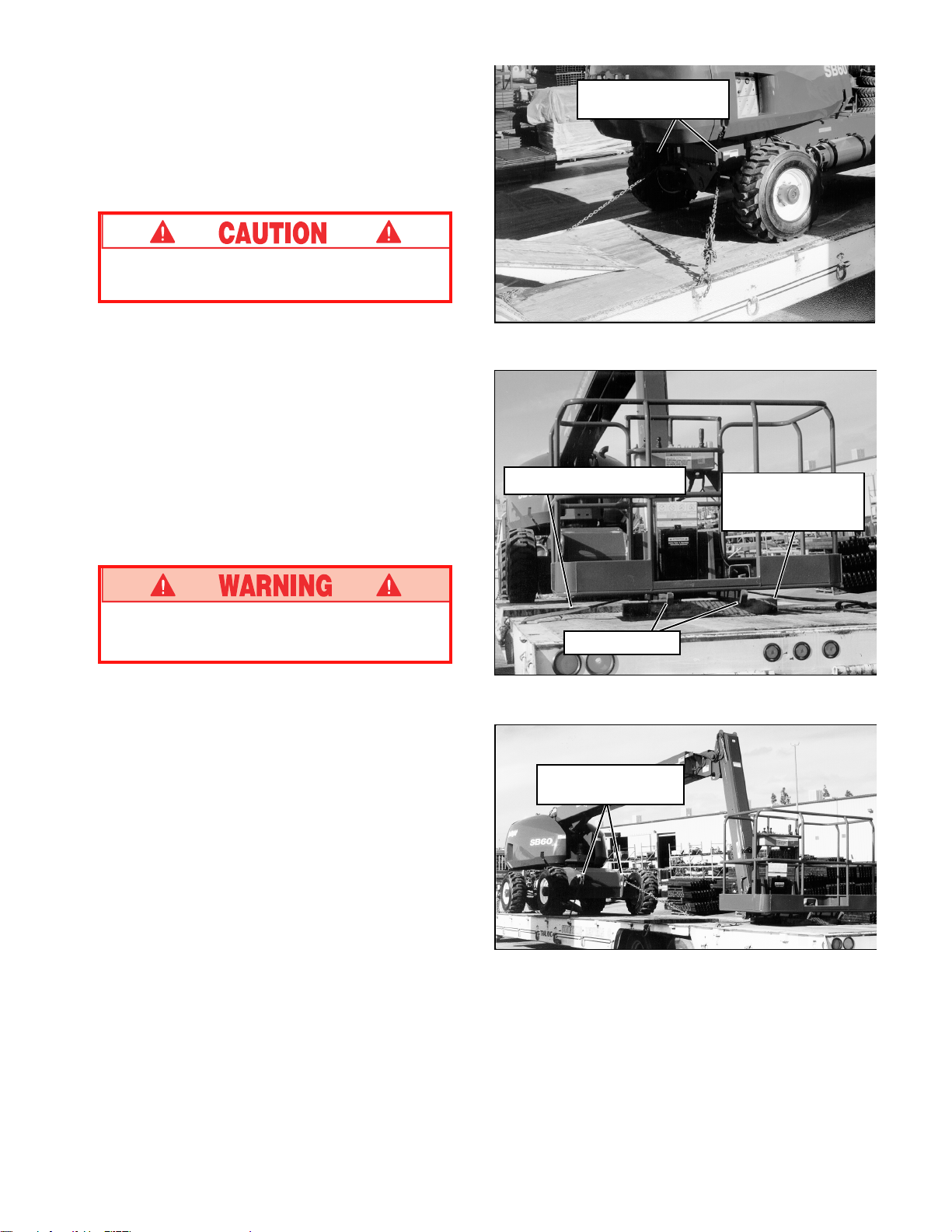
6. Secure the machine to the transport vehicle using
chains / straps of adequate load capacity (refer to
specifications, back page) attached to chassis tie
down lugs. (See Figures 8 and 10).
7. Place wooden block 10 x 20 x 91 cm (4" x 8" x 36")
under platform support braces as shown (Figure 9).
8. Attach straps or chains to cage hold down brackets.
Do not over tighten.
Chassis Tie Down
Lifting Lugs
Figure 8: Front chassis tie down lifting lugs.
Platform Tie Down Strap
Wooden Block
4" x 8" x 36"
(10 x 20 x 91 cm)
NEVER elevate the machine while on a truck or
trailer.
Support Braces
Figure 9: Securing the machine for transportation.
Chassis Tie Down
Lifting Lugs
Figure 10: Rear chassis tie down lifting lugs.
9
Page 10
Maintenance
FUELING
Use a ladder or platform when fueling SB80.
DO NOT stand on tires when fueling the
machine.
Diesel
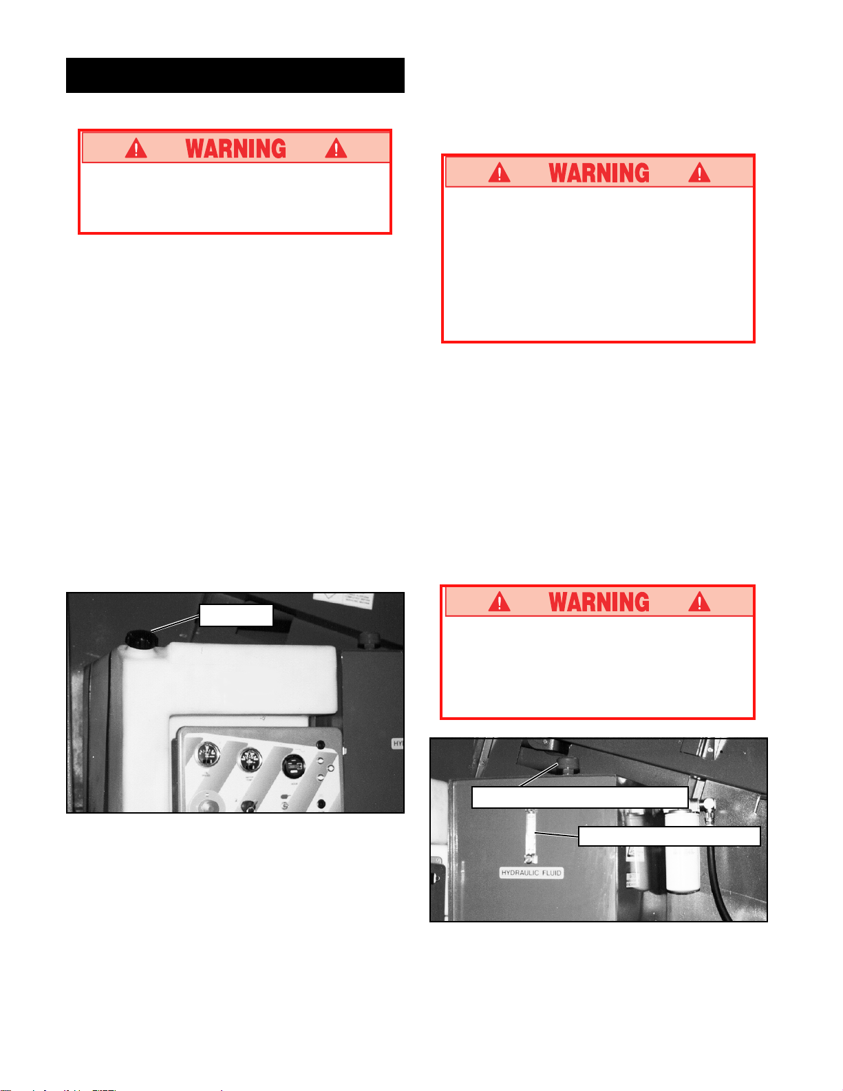
1. Open left turret cover, open fill pipe cap. (See
figure 13)
2. Fill to capacity with diesel motor fuel. Use diesel fuel
as per EN950, do not use residual or blend.
3. Fuel tank full capacity is 159 L (42 US gallons).
HYDRAULIC FLUID
1. Open left turret cover and check oil level at sight
gauge with the boom stowed and retracted. Engine
running or stopped. (See Figure 14)
2. If necessary, fill to capacity with clean ISO compatible hydraulic fluid (ISO 46 summer/ ISO 32 winter).
Refer to Routine Service Table on page 11.
3. Clean area around cap before opening.
4. Open filler / breather cap to add hydraulic fluid.
5. Replace cap.
LUBRICATION
Refer to service manual for lubrication chart and guidelines.
BATTERY MAINTENANCE
Hazard of explosive gas mixture. Keep sparks,
flame and smoking materials away from batteries.
Always wear safety glasses when working with
batteries.
Battery fluid is highly corrosive. Rinse away any
spilled fluid thoroughly with clean water.
Check battery fluid level daily, especially if work platform
is being used in a warm, dry climate.
If electrolyte level is lower than 10 mm (3/8 in.) above
plates add distilled water only. DO NOT use tap water it
will shorten battery life.
Keep terminals and top of battery clean.
TIRES
Tire selection can affect the stability of the machine.
Use only tires supplied by UpRight unless approved by
the manufacturer in writing. Check air filled tire air
pressure daily 7 bar (100 psi).
Fuel cap
Figure 13: Fuel tank
Do not operate machines with Elev8 option
unless machine is equipped with foam filled
tires. Remove machine from service and install
proper tire/wheel combination before operating
machine.
Hydraulic Oil Filler / Breather Cap
Hydraulic Oil Level Gauge
Figure 14: Hydraulic Oil Tank
10
Page 11

ROUTINE SERVICE
Use the following table as a guide for routine maintenance. Inspection and maintenance shall be
performed by personnel who are trained and familiar with mechanical and electrical procedures. Refer
to the Service Manual for complete service instructions.
Please copy this page and use the Routine Service
Table as a checklist when inspecting a machine for
service.
Routine Service Table
Routine Service Table Key
Interval
Daily = each shift (every day) or every eight hours
30D = every month (30 days) or every 50 hours
3M = every 3 months or 125 hours
6M = every 6 months or 250 hours
1Y = every year or 500 hours
2Y = every 2 years or 1000 hours
A = Acceptable
N = No/Not Acceptable
R = Repaired/Acceptable
COMPONENT INSPECTION OR SERVICES INTERVAL A N R
Engine Oil Check level and condition Daily
Engine Fuel Check fuel level Daily
System Check for leaks Daily
Batteries Check electrolyte level Daily
Engine Check coolant level (with engine cold) Daily
Coolant Replace coolant 2Y
Hydraulic Check level Daily
Fluid Change filter 6M
* See note Drain and replace 2Y
Hydraulic Check for leaks Daily
System Check hose connections 30D
Emergency Check operation of emergency override Daily
Hydraulic power unit
System
Controller Check operation of all controls Daily
Control Check the exterior of the cable Daily
Cable for pinching, binding or wear
Platform Check fasteners for proper torque Daily
Floor and Check welds for cracks Daily
Rails Check condition of platform Daily
Tires Check for damage Daily
Hydraulic Wipe clean 30D
Pump Check for leaks at mating surfaces 30D
Hydraulic Check hydraulic drive motor operation Daily
Drive System Check hoses, fittings, and valve block
Check for leaks Daily
Change oil & filter (Dual Fuel) 200 HOURS
Change oil & filter (Diesel) 500 HOURS
Replace fuel filter 6M
Check air cleaner 30D
Clean exterior 3M
Clean terminals 3M
Check hoses for exterior wear 30D
Check condition of anchorage points Daily
Check condition of operators manual Daily
Check air pressure (7 bar [100 psi]) Daily
Check lug nuts (torque to 260 ft. lbs. [352 Nm]) 30D
Check for hose fitting leaks Daily
Check mounting bolts for proper torque 30D
for leaks
Daily
COMPONENT INSPECTION OR SERVICES INTERVAL A N R
Steering Check fittings for proper torque 6M
System Check steering cylinder for leaks 30D
Check linkage for wear areas 30D
Elevating Inspect for structural cracks Daily
Assembly Check pivot points for wear 30D
Chassis Check hoses for pinch or rubbing points Daily
Axles Grease Wear Pads on Extending Axles 20H
Turret Check ring gear for proper lubrication
Torque Check for leaks Daily
Hubs Check oil level 250H/6M
Lift Check the cylinder rods for wear 30D
Cylinders Check pivot pin retaining bolts
Entire Check for and repair collision damage Daily
Unit Check fasteners for proper torque 3M
Labels Check for peeling, missing, or unreadable
Check for missing / loose retainers Daily
Check pivot pin retaining bolts
for proper torque
Check members for deformation Daily
Check component mounting
for proper torque
Check swing bearing bolt (torque to
352 Nm [260 ft. lbs.])
Check welds for cracks Daily
and wear
Check planetary oil level 150H/3M
Lubricate ring gear (MoS2 grease) 150H/3M
Change oil after break-in period 50H/30D
Change oil (SAE 90 gear oil) 2000H/2Y
Wheel drive mounting hardware to 298 Nm
(220 ft. lbs.)
for proper torque
Check seals for leaks 30D
Inspect pivot points for wear 30D
Check fittings for proper torque 30D
Check for corrosion, remove and repaint 3M
Lubricate 30D
labels & replace
30D
6M
6M
Daily
6M
30D
Daily
ISO grade 46, for temperature range of 4oC (40oF) up to 43oC (110oF).
*For colder climates:
ISO grade 32, for temperature range of -12oC (10oF) up to 18oC (65oF)
Service Report
Date: ____________
Owner: ___________________
Model No: ________________Serial No: _______________
Serviced By: _______________
Service Interval: ____________
11
Page 12
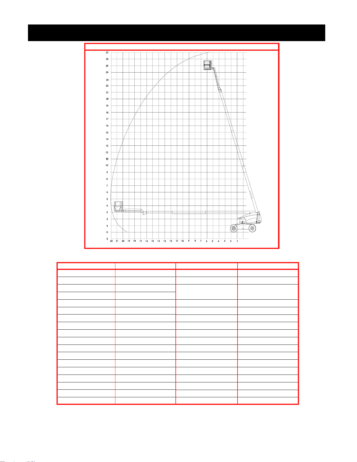
Specifications*
REACH ENVELOPE DIAGRAM
DIMENSIONS IN METRES
ITEM SPECIFICATION
Working height maximum 26.4 m (86 ft.)
Platform height maximum 24.4 m (80 ft.)
Platform step in height 0,3 m (12 in.)
Drivable height 8 m (26.2 ft.)
Horizontal outreach 22 m (72 ft.)
Turret rotation 360 deg. continuous
Platform rotation 180 deg.
Tail swing 0.99 m (Axles extended)
Jib length 2.4 m (8 ft.)
Jib arc 140 deg.
Inside turning radius 3.01 m (10 ft.)
Drive speed (lowered) 5.23 km/h (3.25 mph)
Drive speed (elevated) 1.12 km/h (0.7 mph)
Gradability Diesel 40%
Platform Size 1,8 m Std. 2,4 m Optional
Tires 15-22.5 16 ply lug tread (7 bar)
Tires (Elev8 Option) 18-22.5 18 ply foam filled
Controls Electric Proportional
ITEM SPECIFICATION
Guardrail height 1.1 m (45 in.)
Toeboards 0.15 m (6 in.)
Maximum (Unrestricted)
platform capacity 272 kg (600 lb.)
Maximum no. of occupants 2
Weight \ Diesel 14696 kg (32,400 lb.)
Weight (Elev8 Option) +998 kg (+2200 lb.)
Overall height (Stowed) 2.7 m (9 ft.)
Overall length (Stowed) 11.5 m (37 ft. 8 in.)
Overall width 2.4 m (8 ft.)
Overall width (Extended) 3.2 m (10 ft. 6 inches)
Overall width (Elev8) 0.10 m (+ 4 inches)
Wheel base 2.9 m (9 ft. 6 in.)
Ground Clearance 0.28 m (11 in.)
Power source \ Diesel Perkins 1004-42 86 hp
System voltage 12VDC
Maximum Hyd. Pressure 345 bar (5000 psi)
Sound Level 80 dB
* Specifications subject to change without notice. Refer to Service Manual for parts and
service information.
12
Page 13
Version française
RÈGLES DE SÉCURITÉ
Danger de basculementDanger délectrocution
Danger de collision
Danger de chute
CETTE MACHINE
N’EST PAS ISOLÉE.
UTILISATION DE LA PLATE-FORME ÉLÉVATRICE DE TRAVAIL: Cette plate-forme élévatrice de travail est conçue pour soulever des
personnes et leurs outils, ainsi que le matériel nécessaire au travail. Elle EST conçue pour les travaux de réparation et dassemblage ainsi que
les travaux sur postes de travail aériens (plafonds, grues, structures de toit, bâtiments, etc.). Toute autre utilisation de la plate-forme élévatrice
de travail est interdite !
CETTE PLATE-FORME ÉLÉVATRICE DE TRAVAIL NEST PAS ISOLÉE ! Cest pourquoi il est impératif de conserver une distance de
sécurité des pièces sous tension de léquipement électrique !
TOUS les occupants doivent porter un dispositif antichute dun modèle agréé, correctement fixé au point de fixation de la plate-forme conçu à
cet effet. Ne fixer quun seul dispositif antichute par point de fixation.
Il est interdit dexcéder la charge maximale autorisée spécifiée de 272 kg (600 lb) y compris 2 personnes sur la plate-forme !
Il est interdit dutiliser et de manoeuvrer la plate-forme élévatrice de travail comme outil de levage ou comme grue (pour soulever des
charges de bas en haut ou de haut en bas !
NE JAMAIS dépasser 200 N (45 lb) de force latérale par occupant.
RÉPARTIR également toutes les charges sur la plate-forme.
NE JAMAIS utiliser la machine sans avoir dabord vérifié si la surface de la zone de travail ne présente pas de dangers tels que des trous, des
dénivellations, des bosses, des bordures ou des débris et sans sêtre assuré quon peut les éviter.
MANOEUVRER la machine uniquement sur des surfaces capables de supporter la charge des roues.
NE JAMAIS utiliser la plate-forme lorsque la vitesse du vent dépasse 45 km/h (28 mi/h = 12,5 m/s) échelle de Beaufort 6.
EN CAS DURGENCE, appuyer sur le bouton darrêt durgence pour désactiver toutes les fonctions alimentées.
Il est interdit de grimper ou de se tenir debout sur le garde-corps de la plate-forme, ou de passer de la plate-forme à des bâtiments, des
structures en acier ou préfabriquées en béton !
Il est interdit de démonter le portillon pivotant ou la barre basculante ou tout autre élément du garde-corps ! Toujours sassurer que le
portillon pivotant ou la barre basculante est fermée et correctement verrouillée ! Il est interdit de maintenir le portillon pivotant ou la barre
basculante en position ouverte (p. ex. en la tenant ouverte avec des sangles darrimage) lorsque la plate-forme est élevée !
Il est interdit de rallonger la hauteur ou le rayon daction en plaçant des échelles, des échafaudages ou autres dispositifs similaires sur la
plate-forme !
VÉRIFIER la machine à fond, avant de lutiliser, afin dy déceler toute soudure fissurée, toute pièce de fixation ayant du jeu ou qui manquerait,
toute fuite du circuit hydraulique, toute connexion lâche et tout câble ou tuyau qui serait endommagé.
SASSURER que toutes les étiquettes sont en place et bien lisibles avant dutiliser la machine.
NE JAMAIS utiliser une machine qui est endommagée, qui ne fonctionne pas correctement, ou dont les étiquettes sont endommagées ou
manquantes.
SI LALARME RETENTIT lorsque la flèche est élevée, ARRÊTER, rentrer la flèche avec précaution et abaisser la plate-forme sans faire
pivoter la machine. Amener la machine jusque sur une surface horizontale solide.
Omettre dutiliser un équipement de sécurité quel quil soit est interdit et représente un danger pour les personnes situées sur la plate-forme
élévatrice de travail et dans sa zone de travail.
NE JAMAIS charger la batterie daccumulateurs près dune flamme ou dune source détincelles. Les batteries dégagent de lhydrogène
gazeux explosif lorsquelles rechargent.
Les modifications à la plate-forme élévatrice de travail sont interdites sauf autorisation approuvée par UpRight.
Il est interdit de fixer ou dutiliser des composants non fabriqués ou fournis par UpRight !
NE JAMAIS remorquer la machine. La transporter uniquement à laide dun camion ou dune remorque.
APRÈS AVOIR UTILISÉ la plate-forme élévatrice, tourner les deux clés de linterrupteur à la position darrêt (« OFF »), puis les retirer afin de
prévenir lutilisation de la plate-forme par toute personne non autorisée.
NE JAMAIS utiliser le bras
articulé à flèche ni conduire
la plate-forme élevée sans
que la machine ne soit sur
une surface horizontale
solide.
NE JAMAIS positionner la
plate-forme sans sêtre
dabord assuré quil ny a
pas dobstacles ou autres
sources de danger aux
alentours.
NE JAMAIS monter,
sasseoir ou se tenir debout
sur les rampes du gardecorps.
13
Page 14

Introduction
Ce manuel couvre lutilisation des modèles de bras
articulé SB-80 à moteur à combustion interne. On
veillera à le garder sur la machine en tout temps.
Vérification préliminaire
de sécurité et dutilisation
Lire dabord attentivement toutes les règles de
sécurité, les étiquettes et le mode demploi, en
sassurant de les comprendre et de sy conformer.
Chaque jour avant dutiliser la machine, exécuter les
tâches suivantes :
Effectuer une inspection visuelle complète de la machine avant de lutiliser. Porter une attention particulière
aux points suivants :
1. Ouvrir les panneaux, et vérifier que les composants
des circuits hydrauliques/les tuyaux ne présentent
pas de fuites ni de dommages. Vérifier quaucun
composant de linstallation électrique ne présente de
dommages ni de connexions lâches.
2. Vérifier à fond le châssis, les essieux, les moyeux,
et la timonerie de direction pour sassurer quils ne
présentent pas de dommages, de déformations, de
peinture boursouflée, de pièces de fixation ayant du
jeu ou qui manquent, ni de soudures fissurées.
3. Vérifier si les pneus sont endommagés, crevés ou
dégonflés; la pression des pneus doit être de 7 bar
(100 lb/po2).
4. Vérifier létat dusure de tous les tuyaux / câbles.
5. Vérifier le dispositif délévation pour sassurer quil
ne présente pas de dommages, de déformations, de
peinture boursouflée, de pièces de fixation ayant du
jeu ou qui manquent, ni de soudures fissurées.
6. Vérifier la plate-forme et les garde-corps pour
sassurer quils ne présentent pas de dommages, de
déformations, de peinture boursouflée, de pièces de
fixation ayant du jeu ou qui manquent, ni de
soudures fissurées. Sassurer que le portillon
fonctionne librement.
7. La plate-forme étant abaissée complètement, vérifier
le niveau dhuile hydraulique.
8. Vérifier le niveau délectrolyte de la batterie. (Voir
Entretien des batteries à la page 21.)
9. Vérifier le niveau de carburant; faire lappoint si
nécessaire. (Voir Ravitaillement en caburant à la
page 21.)
10. Vérifier le niveau dhuile moteur.
NE JAMAIS ôter le bouchon dun radiateur
chaud. Le liquide de refroidissement chaud peut
causer de graves brûlures.
11. Sassurer que le radiateur est froid et vérifier le
niveau du liquide de refroidissement. Faire lappoint
si nécessaire.
ESSAI DE FONCTIONNEMENT DES
ÉLÉMENTS
Nota : Se reporter aux figures 1 à 5 pour obtenir les
emplacements du pupitre de commande sur le
châssis et sur la plate-forme.
IMPORTANT : Avant de réaliser lessai de fonctionnement des éléments, sassurer que les essieux sont
entièrement déployés. Pour les instructions
concernant le déploiement des essieux, se reporter à
la section « Déploiement et escamotage des essieux »
(page 17).
1. Avant deffectuer les essais suivants, vérifier dabord
que laire qui entoure la machine ne présente pas de
dangers tels que des obstacles en surplomb, des
trous, des dénivellations et des débris.
2. Tourner linterrupteur à clé du boîtier de commande
à la position de châssis (« CHASSIS »), puis tirer les
interrupteurs darrêt durgence au tableau de
commande monté sur le châssis ainsi quau tableau
de commande monté sur la plate-forme.
3. Retirer le boulon de blocage. Voir figure 1.
4. Enfoncer le bouton de démarrage du moteur pour
lancer le moteur; le relâcher lorsque le moteur a
démarré.
5. Enfoncer le bouton darrêt durgence du châssis; le
moteur devrait sarrêter. Répéter lessai avec le
bouton darrêt durgence de la plate-forme. Ramener
les deux boutons darrêt durgence à la position
« ON », puis démarrer le moteur.
6. Les essieux étant complètement déployés, essayer
chaque interrupteur de fonction pour élever /
abaisser, déployer / escamoter, effectuer une
rotation gauche / droite de chaque élément de
lensemble élévateur et noter le bon fonctionnement
de la machine. Toutes les fonctions devraient
effectuer le cycle complet en douceur.
7. Tourner linterrupteur à clé du châssis à la position
de plate-forme (« PLATFORM »).
8. Monter la plate-forme et, si les réglementations
nationales lexigent, fixer le dispositif antichute agréé
au point de fixation de la plate-forme conçu à cet
effet. Nattacher quun seul dispositif antichute par
point dattache.
9. Tout en engageant le dispositif denclenchement
solidaire à main, déplacer le levier de direction en
avant, puis en arrière. Noter si les fonctions
proportionnelles se déroulent en douceur et si les
freins sappliquent rapidement une fois la commande
relâchée.
10. Tout en engageant le dispositif denclenchement
solidaire à main, actionner le bouton de commande
de direction vers la gauche et vers la droite. Noter si
les roues directrices braquent correctement.
11. Tout en enfonçant linterrupteur à pédale, faire
fonctionner les commandes du bras articulé à
flèche. Noter si le bras articulé à flèche fonctionne
en douceur et si les commandes délévation et
dabaissement du bras articulé à flèche, de rotation
du revolver et de rallonge/retrait de la flèche
fonctionnent de façon proportionnelle à la course du
levier. Noter si la plate-forme se maintient de niveau
lorsque le bras articulé à flèche est élevé.
14
Page 15
NOTA : Le bras articulé à flèche ne se rallongera ou
se retirera au-delà de 45 degrés que si les essieux
sont complètement déployés.
12. Avec le bras articulé à flèche élevé de cinq degrés
ou plus, ou rallongé de 0,30 mètres [1 pi] , utiliser le
levier de direction. Noter que la machine navance
quen marche extra-lente (0,30 m [1 pi] par seconde).
Abaisser la flèche en position escamotée.
13. Appuyer sur le bouton de la sirène dappel. Noter si
le timbre retentit.
NOTA : Linterrupteur denclenchement solidaire à
main ne contrôle que les fonctions de déplacement/
direction et de rotation du bras articulé à flèche.
NOTA : Linterrupteur denclenchement solidaire à
pédale ne contrôle que les fonctions du bras articulé
à flèche.
14. Mettre la plate-forme de niveau lorsquelle se trouve
en position escamotée.
NE PAS utiliser une machine qui est
endommagée ou défectueuse. Étiqueter cette
machine et la mettre hors service jusquà ce
quelle ait été réparée.
Commandes et indicateurs
1
2
5
4
9
8
12
13
Figure 4 : Emplacement des commandes sur le
1. Manomètre à huile
2. Indicateur de température de
3. Compteur horaire
4. Bouton darrêt durgence
5. Interrupteur à clé
6. Bouton de démarrage du moteur
7. Bougie de préchauffage (diesel seulement)
8. Alimentation aux. pour abaissement durgence seul.
9. Mise en service de fonction
10. Commande du bras articulé à flèche
11. Commande de la rallonge de la flèche
12. Commande du revolver
13. Commande du bras en porte-à-faux
14. Rotation de la nacelle
15. Commande du niveau de la nacelle
16. Coupe-circuit
18 19
20
châssis
21
liquide de refroidissement
22
17
23
24
3
16
6
7
10
11
14
15
25
26
27
34
Figure 1 : Emplacement des commandes
sur la plate-forme
Figure 2 :
Goupille de blocage
Figure 3 :
Interrupteur à pédale
35
30
29
28
Figure 5 : Emplacement des commandes sur la
plate-forme
17. Déploiement/escamotage des essieux
18. Phares (facultatifs)
19. Génératrice (facultative)
20. Bouton davertisseur sonore
21. Bouton darrêt durgence
22. Indicateur dessieux déployés
23. Témoin lumineux dinclinaison
24. Témoin lumineux de basse pression dhuile
25. Sélecteur de couple/vitesse
26. Bougie de préchauffage (diesel seulement)
27. Alimentation aux. pour abaissement durgence seul.
28. Commande délévation/abaissement du bras articulé et de
rotation du revolver
29. Rallonge/retrait de la flèche
30. Rotation de la nacelle
31. Élévation/abaissement du bras en porte-à-faux
32. Mise à lhorizontale de la nacelle
33. Levier de direction/denclenchement solidaire
34. Bouton de démarrage du moteur
35. Interrupteur denclenchement solidaire à pédale
31
32
33
15
Page 16

Utilisation
Avant dutiliser la plate-forme élévatrice, sassurer :
Que la vérification préliminaire de sécurité et
dutilisation a été effectuée, et que tout écart noté
est corrigé.
Que lessai de fonctionnement des éléments a bien
été réalisé.
Que lopérateur a reçu une formation pratique qui lui
a permis de bien connaître lutilisation de la
machine.
Que laire de travail est exempte de tout obstacle,
trou ou dénivellation et de toute personne qui se
trouverait sur la voie de passage.
Que la surface peut supporter la charge des roues.
Voir les emplacements des commandes aux figures 1 à
5.
Arrêt durgence
À tout moment pendant lutilisation, si une situation
durgence se présente, appuyer sur le bouton darrêt
durgence pour arrêter toutes les fonctions.
Démarrage du moteur
À partir du tableau de commande
monté sur le châssis
1. Tourner linterrupteur à clé à la position châssis
(« CHASSIS »).
2. Appuyer sur le bouton de démarrage pour lancer le
moteur. Relâcher le bouton lorsque le moteur
démarre.
3. Moteurs diesel : Lorsque le moteur est froid,
enfoncer et maintenir le bouton de préchauffage
pendant 6 secondes avant de démarrer le moteur.
À partir du tableau de commande
monté sur la plate-forme
1. Tourner linterrupteur à clé à la position plate-forme
(« PLATFORM »).
2. Tourner linterrupteur rotatif de la plate-forme
complètement dans le sens horaire pour lancer le
moteur. Relâcher linterrupteur à clé lorsque le
moteur démarre.
3. Moteurs diesel : Lorsque le moteur est froid,
enfoncer et maintenir le bouton de préchauffage
pendant 6 secondes avant de démarrer le moteur.
Avertisseur sonore
À tout moment pendant lutilisation, appuyer si
nécessaire sur le bouton de lavertisseur sonore pour
faire retentir une alarme.
Toujours porter un dispositif antichute dun
modèle agréé, correctement fixé au point de
fixation de la plate-forme conçu à cet effet
lorsquon conduit ou utilise la machine (voir
figure 6).
Ne fixer quun seul dispositif antichute par point
de fixation.
Figure 6 : Point de fixation type pour dispositif
antichute
Conduite
Bras articulé à flèche baissé
1. Tourner linterrupteur à clé du tableau de commande
monté sur le châssis à la position plate-forme
(« PLATFORM »), tirer linterrupteur darrêt
durgence du châssis.
2. Monter la plate-forme et fermer le garde-corps
coulissant.
3. Si les réglementations nationales lexigent, fixer un
dispositif antichute agréé au point de fixation de la
plate-forme conçu à cet effet. Nattacher quun seul
dispositif antichute par point dattache.
4. Démarrer le moteur.
5. Vérifier que laire de travail est exempte de tout obstacle,
de tout trou/dénivellation et de toute personne qui se
trouverait sur la voie de passage, et que la surface peut
supporter la charge des roues.
6. Engager linterrupteur denclenchement solidaire, et
amener le levier de direction en avant pour se diriger
en marche avant, ou vers larrière, pour se diriger en
marche arrière.
Nota : Lorsque le bras articulé à flèche a pivoté à
lavant du châssis (roues directrices à larrière), les
sens de marche se trouvent inversés par rapport à
la position du levier de direction. Remarquer les
flèches de couleur codées sur le panneau de
commande situé près du levier de direction, et sur
le châssis. Elles indiqueront le sens de la marche
lorsquon manoeuvre le levier de direction.
16
Page 17

Déploiement et
escamotage des
essieux
À partir du tableau de commande
monté sur la plate-forme
IMPORTANT : Les essieux doivent être
complètement déployés pour permettre lextension
ou lélévation de la flèche au-delà de 45o. La
machine doit être conduite en marche avant ou en
marche arrière pendant le déploiement des essieux.
Sassurer que les quatre roues sont bien toutes
visibles et quaucune personne ni obstacle ne se
trouve dans la voie de passage de la machine.
1. Manoeuvrer et maintenir le bouton de déploiement/
escamotage des essieux pour les fonctions de
déploiement ou descamotage.
2. Conduire la machine en marche avant ou en marche
arrière. Les essieux vont se déployer ou sescamoter.
3. Une fois les essieux complètement déployés,
lindicateur dessieux déployés (le voyant lumineux
vert sur le panneau de commande de la plate-forme)
sallume.
NOTA : Vérifier que les barres jaunes sont visibles
sur les quatre essieux lors du déploiement complet
de ces derniers.
4. Resynchroniser la géométrie de direction en
tournant la direction complètement vers la gauche
ou vers la droite et en conservant la position
pendant quelques secondes.
5. Toutes les fonctions du bras articulé à flèche sont
maintenant disponibles.
Bras articulé à flèche élevé
Déplacer le bras articulé à flèche élevé
exclusivement sur surfaces horizontales solides.
En conduite bras articulé à flèche élevé, la machine
navance quen marche extra-lente (0,30 m [1 pi] par
seconde).
Direction
1. Tout en engageant le levier denclenchement
solidaire à main, pousser le bouton de commande
de direction (situé en haut du levier de commande)
pour tourner à gauche ou à droite.
Nota : La direction nest pas à centrage automatique. Les roues doivent être remises en position
droite à laide du bouton de commande de direction.
Cette machine nest pas isolée.
Observer les normes nationales
en matière de sécurité, et garder
CETTE MACHINE
NEST PAS ISOLÉE.
la distance sécuritaire requise
lorsque vous travaillez à proximité
déquipement sous tension.
POSITIONNEMENT DE
LA PLATE-FORME
Une certaine planification préalable est nécessaire pour
positionner la plate-forme le plus près possible de laire
de travail. Tout dabord, vous devez inspecter laire de
travail et trouver un emplacement adéquat pour garer
lengin. Il doit se trouver sur un terrain plat solide aussi
proche que possible de la zone de travail. Tenir compte
de tous les obstacles qui peuvent se trouver au sol ou
en hauteur, et les éviter.
Avant de commander une fonction quelconque, toujours
vérifier quil ny a aucun obstacle ni conducteur
électrique autour et au-dessus de la machine.
Commandes multifonctions
Le modèle UpRight SB-80 utilise des commandes
multifonctions. Cela signifie que trois fonctions
quelconques peuvent être utilisées simultanément, à
plein régime.
Au besoin, on peut faire pivoter le revolver tout en
conduisant pour effectuer des virages étroits.
Utilisation des commandes montées
sur le châssis
Ne pas manoeuvrer la machine à partir des
commandes montées sur le châssis si
quelquun se trouve sur la plate-forme.
Toutes les fonctions du bras articulé à flèche se
dérouleront à vitesse fixe.
1. Tourner linterrupteur à clé du tableau de commande
monté sur le châssis.
2. Pendant que la moteur tourne, manoeuvrer les
interrupteurs de commande de la flèche pour
positionner la plate-forme.
Mise à lhorizontale
de la plate-forme
NE PAS utiliser la machine si la plate-forme ne
se maintient pas de niveau lorsque élevée.
Tout en enfonçant du pied linterrupteur à pédale,
amener le bouton de commande de positionnement
horizontal de la plate-forme en avant pour envoyer la
plate-forme vers le haut, et le ramener en arrière pour
envoyer la plate-forme vers le bas. Relâcher le bouton
de commande pour arrêter la manoeuvre de mise à
lhorizontale.
17
Page 18

Rotation du revolver
FONCTIONNEMENT DE SECOURS
En cas de panne de lengin, il est possible dabaisser
manuellement le dispositif délévation en observant la
marche à suivre ci-après.
Tout en enfonçant du pied linterrupteur à pédale,
amener le levier de commande de rotation du bras
articulé à flèche à droite, pour faire tourner le revolver
vers la droite, et à gauche, pour le faire tourner vers la
gauche. Relâcher linterrupteur pour arrêter la rotation.
La vitesse de la rotation du revolver sera proportionnelle
à la course du levier de commande. Sassurer que la
zone entourant le bras articulé à flèche est exempte de
tout obstacle avant deffectuer la rotation du revolver.
Élévation de la flèche
Tout en enfonçant du pied linterrupteur à pédale,
amener le levier de commande vers lavant pour élever
la flèche et le ramener en arrière pour abaisser celle-ci.
Relâcher le levier de commande pour arrêter la manoeuvre délévation/dabaissement. Lélévation de la
flèche fonctionne à une vitesse proportionnelle à la
course du levier de commande.
Déploiement de la flèche
NE JAMAIS descendre du dispositif délévation
en position élevée. Si les commandes ne
répondent pas, observer la marche à suivre
dabaissement durgence.
Abaissement du dispositif
délévation
1. Engager linterrupteur du bloc dalimentation
auxiliaire.
2. Actionner toute fonction du bras articulé à flèche de
la façon habituelle.
Nota : La batterie auxiliaire permet un (1) cycle
dabaissement durgence et doit être rechargée
ensuite. Elle se recharge lorsque le moteur tourne.
REMORQUAGE DE SECOURS
Caler les roues avant de désengager les
moyeux. La machine risque de rouler.
Tout en enfonçant du pied linterrupteur à pédale, amener
vers larrière le levier de commande de la rallonge de
flèche pour déployer la flèche, lamener vers lavant pour
escamoter la flèche. Relâcher le levier de commande pour
arrêter la manoeuvre de déploiement/descamotage. Le
déploiement de la flèche fonctionnera à une vitesse
proportionnelle à la course du levier de commande.
Élévation du bras
en porte-à-faux
Tout en enfonçant du pied linterrupteur à pédale,
amener le levier de commande du bras en porte-à-faux
vers lavant pour élever le bras en porte-à-faux, et
lamener vers larrière pour abaisser le bras. Relâcher le
levier de commande pour arrêter la manoeuvre
délévation/dabaissement.
Rotation de la plate-forme
Tout en enfonçant du pied linterrupteur à pédale,
commuter linterrupteur de commande vers la gauche,
pour faire tourner vers la gauche, ou vers la droite, pour
faire tourner vers la droite. Relâcher linterrupteur pour
arrêter la rotation.
NE PAS remorquer la machine à une vitesse
supérieure à 5 km/h (3 mi/h). Un déplacement à
une vitesse supérieure à celle-ci endommagera
les composants dentraînement et annulera la
garantie.
Il ny a pas de frein lorsque les chapeaux
centraux sont installés en position inversée.
Nexécuter les opérations suivantes que lorsque la
machine refuse de fonctionner de façon autonome et
quil est nécessaire de la déplacer, ou lorsquon veut la
hisser au treuil sur une remorque pour fin de transport.
NE PAS utiliser une machine qui est
endommagée ou défectueuse. Étiqueter cette
machine et la mettre hors service jusquà ce
quelle ait été réparée.
18
Page 19

1. Sassurer que la plate-forme est complètement
abaissée et que le revolver est tourné de telle sorte
que la plate-forme se trouve à larrière de la
machine.
2. Se reporter à la figure 7, et désengager les quatre
moyeux de roue dentraînement. Déposer les deux
(2) vis ainsi que le chapeau central. Poser de
nouveau le chapeau central mais en sens contraire.
3. Fixer une chaîne/un câble adéquat et suffisamment
résistant pour remorquer la machine aux étriers
darrimage avant ou arrière.
4. Une fois prêt à emmener la machine, retirer les
cales des roues. Remorquer ou tirer à laide dun
treuil lengin en position, puis remettre les cales en
place.
5. Réengager les quatre moyeux dentraînement en
replaçant chaque chapeau central selon son
orientation dorigine.
Moyeu
dentraînement
MACHINES ÉQUIPÉES DE LOPTION
ELEV-8
Les machines équipées de loption Elev8 sont capables
dutiliser toutes les fonctions sur une pente solide à
3 degrés.
Utiliser les machines munies de loption Elev8
uniquement si la machine est équipée de pneus
remplis de mousse. Mettre la machine horsservice et installer lensemble pneu/roue
adéquat avant dutiliser la machine.
Si lalarme du détecteur dinclinaison retentit et
que la machine ne fonctionne pas, il faut
escamoter le bras articulé à flèche, abaisser la
plate-forme et déplacer la machine vers une
surface solide à moins de 3 degrés de pente.
Chapeau
central
Vis
Figure 7 : Moyeux dentraînement (montrés en
position de fonctionnement)
APRÈS UTILISATION, TOUS
LES JOURS
1. Abaisser à fond la plate-forme.
2. Stationner la machine sur une surface plane, de
préférence à labri des vandales, et protégée des
enfants et de toute personne qui pourrait
éventuellement sen servir sans autorisation.
3. Enfoncer les deux boutons darrêt durgence.
4. Tourner la clé de linterrupteur à la position darrêt
« OFF », puis la retirer afin de prévenir lutilisation
de la plate-forme par toute personne non autorisée.
Transport
IMPORTANT : Les essieux doivent être complètement rentrés avant de transporter la machine. La
machine doit être dirigée en marche avant ou en
marche arrière pendant lescamotage des essieux.
Sassurer que les quatre roues sont bien toutes
visibles et quaucune personne ni obstacle ne se
trouve dans la voie de passage de la machine.
1. Actionner le bouton de déploiement/escamotage des
essieux pour la fonction descamotage.
2. Conduire la machine en marche avant ou en marche
arrière. Les essieux vont sescamoter.
3. Une fois les essieux complètement escamotés,
lindicateur dessieux escamotés (situé sur le
panneau de commande de la plate-forme) sallume.
4. La machine peut maintenant être chargée pour le
transport.
PAR GRUE
1. Sassurer que la flèche est complètement abaissée
et escamotée.
2. Fixer des sangles aux étriers de levage du châssis
seulement. Sassurer que les sangles sont réglées à
une tension suffisante pour maintenir la machine de
niveau au cours de la manoeuvre de levage.
19
Se tenir à lécart de la machine pendant la
manoeuvre de levage.
Vérifier les caractéristiques techniques au verso
pour sassurer que la grue et les élingues sont
dune capacité suffisante pour lever la masse
de la machine.
Page 20

PAR CAMION OU REMORQUE
1. Sassurer que la flèche est complètement abaissée
et escamotée.
2. Manoeuvrer la machine jusque sur la plate-forme du
camion/de la remorque.
3. Au moment du hissage au treuil, suivre les
instructions pour le remorquage de secours données
en page 18. Fixer le câble de treuillage aux étriers
darrimage avant.
Ne pas déplacer la machine au treuil à plus de
5 km/h (3 mi/h).
4. Après le remorquage au treuil, sassurer que les
quatre (4) moyeux dentraînement sont réengagés
en replaçant chaque chapeau central selon son
orientation dorigine.
5. Installer la goupille de blocage pivotante.
6. Attacher solidement la machine au véhicule de
transport à laide de chaînes/sangles dune capacité
de charge adéquate (se reporter à la fiche technique
au verso de cette page) fixées aux étriers darrimage
du châssis (voir figures 8 et 10).
7. Placer des blocs de bois de 10 cm x 20 cm x 91 cm
(4 po x 8 po x 36 po) sous les poutrelles de support
de la plate-forme comme le montre lillustration
(figure 9).
8. Fixer des sangles ou des chaînes aux crochets de
maintien de la nacelle. Éviter de serrer à bloc.
Étriers darrimage-
levage du châssis
Figure 8 : Étriers darrimage-levage
du châssis avant
Sangle darrimage
de la plate-forme
1
0 cm x 20 cm x 91 cm
(4 po x 8 po x 36 po)
Poutrelles de support
Blocs de bois
NE JAMAIS lever la machine lorsquelle se
trouve sur un camion ou une remorque.
Figure 9 : Assujettissement de lengin
pour le transport
Étriers darrimage-levage
du châssis
Figure 10 : Étriers darrimage-levage
du châssis arrière
20
Page 21

Entretien
RAVITAILLEMENT EN CARBURANT
Utiliser une échelle ou une plate-forme pour
ravitailler le SB80 en carburant. NE PAS se
tenir sur les pneus lors du ravitaillement en
carburant.
LUBRIFICATION
Voir la table de lubrification et les lignes directrices
appropriées dans le Manuel dentretien.
ENTRETIEN DES BATTERIES
Risque démanations gazeuses explosives.
Tenir les batteries loin de toute source
détincelles, de flammes et de fumée.
Diesel
1. Ouvrir le carter du revolver, ouvrir le bouchon du
tube de remplissage. (Voir figure 13)
2. Faire le plein avec du carburant pour moteurs diesel
uniquement. Utiliser du diesel suivant la norme
EN950, ne pas utiliser dhuile lourde ni de mélange
de carburants.
3. La capacité totale du réservoir de carburant est de
159 L (42 gallons US).
LIQUIDE HYDRAULIQUE
1. Ouvrir le carter du revolver gauche, et vérifier le
niveau dhuile hydraulique par la jauge de niveau
dhuile, le bras articulé à flèche étant escamoté et
rentré. Moteur en marche ou à larrêt. (Voir
figure 14)
2. Si nécessaire, faire le plein avec du liquide
hydraulique propre aux normes ISO (ISO 46 en été/
ISO 32 en hiver). Se reporter au tableau dentretien
courant, à la page 22.
3. Nettoyer la région autour du bouchon avant de
louvrir.
4. Ouvrir le bouchon reniflard de lorifice de
remplissage pour ajouter lhuile hydraulique.
5. Remettre le bouchon en place.
Bouchon du réservoir
de carburant
Ne jamais manipuler les batteries sans porter
de lunettes de sécurité.
Lélectrolyte (liquide de la batterie) est un
liquide très corrosif. Éliminer toute trace de
liquide déversé de la batterie en rinçant à leau
claire.
Vérifier le niveau délectrolyte tous les jours, surtout si
la machine est utilisée sous les climats chauds et secs.
Si lélectrolyte ne recouvre pas les plaques de batterie
dau moins 10 mm (3/8 po), ajouter de leau distillée
seulement. NE PAS utiliser de leau du robinet, ce qui
réduirait la durée de vie des batteries.
Garder les bornes et le dessus des batteries propres.
PNEUS
Le choix des pneus peut influer sur la stabilité de la
machine. Utiliser uniquement des pneus fournis par
UpRight sauf autorisation écrite du fabricant. Vérifier
quotidiennement que la pression dair des pneus à
chambre à air est de 7 bar (100 lb/po2).
Utiliser les machines munies de loption Elev8
uniquement si la machine est équipée de pneus
remplis de mousse. Mettre la machine horsservice et installer lensemble pneu/roue
adéquat avant dutiliser la machine.
Figure 13 : Réservoir de carburant
Bouchon reniflard de lorifice de
remplissage du réservoir dhuile hydraulique
Jauge de niveau dhuile
hydraulique
Figure 14 : Réservoir dhuile hydraulique
21
Page 22

ENTRETIEN COURANT
Le tableau ci-après sert de guide pour lentretien courant.
Seules les personnes formées qui connaissent les
opérations mécaniques et électriques doivent réaliser la
vérification de contrôle et lentretien de la machine. Les
consignes dentretien se trouvent dans le Manuel dentretien.
Au moment de vérifier la machine, reproduire cette page et
utiliser le tableau qui sy trouve comme liste de vérification.
Tableau d'entreien courant
Légende du tableau
Périodicité
Quot. = chaque poste de travail (chaque jour) ou toutes les
huit heures
J
= chaque mois (30 jours) ou toutes les 50 heures
30
M
= tous les 3 mois ou toutes les 125 heures
3
M
= tous les 6 mois ou toutes les 250 heures
6
A
= chaque année ou toutes les 500 heures
1
A
= tous les 2 ans ou toutes les 1000 heures
2
A = Acceptable
N = Non/non acceptable
R = Réparé/acceptable
ÉLÉMENT VÉRIFICATION OU ENTRETIEN À EFFECTUER
Huile Vérifier le niveau et létat. Quot.
moteur Vérifier sil y a des fuites. Quot.
Changer huile et filtre (modèles à
2 combustibles).
Changer huile et filtre (modèles diesel). 500 HEURES
Circuit Vérifier le niveau de carburant. Quot.
carburant Vérifier sil y a des fuites. Quot.
Remplacer le filtre à carburant. 6M
Vérifier le filtre à air. 30J
Batteries Vérifier le niveau délectrolyte. Quot.
Nettoyer lextérieur. 3M
Nettoyer les bornes. 3M
Liquide de Vérifier le niveau (moteur froid). Quot.
refroid. Remplacer le liquide de refroidissement. 2A
Liquide Vérifier niveau. Quot.
hydraulique Changer le filtre. 6M
* Voir nota Vidanger et remplacer. 2A
Circuit Vérifier sil y a des fuites. Quot.
hydraulique Vérifier le raccordement des tuyaux flexibles. 30J
Vérifier lusure extérieure des tuyaux flexibles. 30J
Syst. hydr. Vérifier le bon fonctionnement du
de secours système de secours bloc dalimentation.
Boîtier de Vérifier le bon fonctionnement de toutes
commande les commandes.
Câble de Vérifier que lextérieur du câble
commande ne présente ni pincement, ni pliure, ni usure.
Plancher Vérifier le serrage des pièces de fixation. Quot.
et rampes Vérifier si les soudures sont fissurées. Quot.
Vérifier létat de la plate-forme. Quot.
Vérifier létat des points de fixation. Quot.
Vérifier létat du Guide de lopérateur. Quot.
Pneus Vérifier le bon état. Quot.
Vérifier la pression dair (7 bar [100 lb/po2]) Quot.
Vérifier les écrous détrier (couple
à 352 Nm [260 lb.pi]).
Pompe Bien essuyer. 30J
hydraulique Vérifier sil y a des fuites aux surfaces
de contact.
Vérifier sil y a des fuites aux raccordements. Quot.
Vérifier le serrage des boulons de fixation. 30J
Système Vérifier le fonctionnement du moteur
dentretien dentraînement hydraulique.
hydraulique Vérifier sil y a des fuites aux tuyaux,
aux raccords et au distributeur.
PÉRIODICITÉ
HEURES
200
Quot.
Quot.
Quot.
30
30
Quot.
Quot.
J
J
AN R
ÉLÉMENT VÉRIFICATION OU ENTRETIEN À EFFECTUER
Système Vérifier le serrage des raccordements. 6M
de direction Vérifier sil y a des fuites au vérin de direction. 30J
Vérifier si la timonerie présente des zones usées. 30J
Vérifier si des dispositifs de retenue ont
du jeu ou manquent.
Dispositif Vérifier si la structure présente des fissures. Quot.
délévation Vérifier lusure des pièces aux points
darticulation.
Vérifier que les boulons de retenue de laxe
darticulation sont correctement serrés.
Vérifier si les organes sont déformés. Quot.
Châssis Vérifier que les tuyaux ne sont pas pincés
et ne présentent pas de point de frottement.
Vérifier que le montage des éléments
est correctement serré.
Vérifier le bouton du roulement pivotant
(couple à 352 Nm [260 lb.pi]).
Vérifier si les soudures sont fissurées. Quot.
Essieux Graisser les patins dusure sur les essieux
de déploiement.
Revolver Vérifier létat de graissage et dusure de la
couronne du train.
Vérifier le niveau dhuile du planétaire. 150H/3M
Lubrifier la couronne du train (graisse au MoS2). 150H/3M
Couple Vérifier sil y a des fuites. Quot.
moyeux Vérifier le niveau de lhuile. 250H /6M
Changer lhuile après la période de rodage. 50H/30D
Changer lhuile (huile pour engrenages SAE 90). 2000H/2A
Pièces de fixation de la direction des roues à
298 Nm [220 lb.pi].
Vérins Vérifier lusure de la tige de vérin. 30J
délévation Vérifier que les boulons de retenue de
laxe darticulation sont bien serrés.
Vérifier sil y a des fuites aux joints . 30J
Vérifier lusure des pièces aux points darticulation. 30J
Vérifier le serrage des raccordements. 30J
Ensemble Vérifier et réparer les dommages provoqués
de la machine par toute collision.
Vérifier le serrage des pièces de fixation. 3M
Vérifier sil y a signes de corrosion;
décaper et peindre au besoin.
Lubrifier. 30J
Étiquettes Vérifier que les étiquettes ne sont pas décollées,
manquantes ou illisibles et les remplacer.
PÉRIODICITÉ
Quot.
30
30
Quot.
M
6
M
6
20
Quot.
M
6
30
Quot.
M
3
Quot.
A N R
J
J
H
J
Norme ISO de qualité 46, pour des températures allant de
o
4
C (40oF) à 43oC (110oF).
*Pour climats très froids:
Norme ISO de qualité 32, pour des températures allant de -
o
12
C (10oF) à 18oC (65oF).
Fiche d'entretien
Date : __________________________________________
Propriétaire :_____________________________________
o
de modèle : ___________ No de série : ____________
N
Nom du technicien : _______________________________
Périodicité d'entretien : _____________________________
22
Page 23

Fiche technique*
SCHÉMA DES PORTÉES
DIMENSIONS EN MÈTRES
ÉLÉMENT CARACTÉRISTIQUES
Hauteur de travail max. 26,4 m (86 pi)
Hauteur max. de la plate-forme 24,4 m (80 pi)
Marche de plate-forme, haut 0,3 m (12 po)
Hauteur max. au déplacement 8 m (26,2 pi)
Portée horizontale 22 m (72 pi)
Rotation du revolver 360 degrés continus
Rotation de la plate-forme 180 degrés
Déportement de larrière 0,99 m (essieux déployés)
Longueur du bras en porte-à-faux 2,4 m (8 pi)
Arc du bras en porte-à faux 140 degrés
Rayon de braquage intérieur 3,01 m (10 pi.)
Vitesse de déplacement (abaissée) 5,23 km/h (3,25 mi/h)
Vitesse de déplacement (élevée) 1,12 km/h (0,7 mi/h)
Pente gravissable max. Diesel 40%
Dim., plate-forme 1,8 m std. 2,4 m en option
Pneus 15-22,5 16 plies, sculpture à barrettes,
7 bar (100 lb/po2)
Pneus (option Elev8) 18 plis, 18 x 22,5, remplis de mousse
Commandes Rég. proportionnelle, électriques
Hauteur, garde-corps 1,1 m (45 po)
Hauteur, plinthes 0,15 m (6 po)
Maximum (illimité)
capacité de la plate-forme 272 kg (600 lb)
Nombre maximum doccupants 2
Poids/Diesel 14696 kg (32400 lb)
Poids (option Elev8) +998 kg (+2200 lb)
Hauteur hors-tout (escamoté) 2,7 m (9 pi)
Longueur hors-tout (escamoté) 11,5 m (37 pi, 8 po)
Largeur hors-tout 2,4 m (8 pi)
Largeur hors-tout (déployé) 3,2 m (10 pi, 6 po)
Largeur hors-tout (Elev8) 0,10 m (+ 4 po)
Empattement 2,9 m (9 pi, 6 po)
Garde au sol 0,28 m (11 po)
Moteur/Diesel Perkins 1004-42 86 hp
Tension du circuit électrique 12 V c.c.
Pression hydraulique maximum 345 bar (5000 lb/po2)
Niveau sonore maximum 80dB
ÉLÉMENT CARACTÉRISTIQUES
* Ces caractéristiques peuvent être changées sans préavis. La liste des pièces et les
consignes dentretien détaillées se trouvent dans le Manuel dentretien.
23
Page 24

Deutschsprachiger Teil
Gefahr der Tötung
durch Stromschlag
SICHERHEITSREGELN
Gefahr des
Umkippens
Kollisionsgefahr
Absturzgefahr
Ausleger NIEMALS betätigen
DIESE MASCHINE
IST NICHT
ISOLIERT!
BENUTZUNG DER HOCHARBEITSBÜHNE: Diese Hocharbeitsbühne dient zum Anheben von Personen und ihren Werkzeugen sowie des
für die Arbeit benötigten Materials. Sie IST für die Ausführung von Reparatur- und Montagearbeiten an hochgelegenen Arbeitsplätzen
(Decken, Kränen, Dachkonstruktionen, Gebäuden usw.) vorgesehen. Sämtliche anderen Einsatzzwecke der Hocharbeitsbühne sind
verboten!
DIE HOCHARBEITSBÜHNE IST ELEKTRISCH NICHT ISOLIERT! Aus diesem Grund ist es dringend erforderlich, von stromführenden
Teilen elektrischer Geräte einen Sicherheitsabstand einzuhalten!
SÄMTLICHE Benutzer müssen einen zugelassenen Haltegurt tragen, der vorschriftsmäßig am dafür vorgesehenen Verankerungspunkt der
Arbeitsbühne befestigt ist. An jedem Verankerungspunkt darf nur ein Haltegurt befestigt werden.
Es ist verboten, die zulässige Höchstbelastung von 272 kg (600 lb) , einschließlich von zwei auf der Arbeitsbühne befindlichen Personen, zu
überschreiten!
Die Verwendung bzw. der Betrieb der Hocharbeitsbühne als Hebevorrichtung oder Kran (Heben oder Absenken von Lasten) ist verboten!
NIEMALS die Querkraft von 200 N (45 lb) pro Benutzer überschreiten.
Alle Lasten stets gleichmäßig auf der Arbeitsbühne VERTEILEN.
Maschine NIEMALS in Betrieb nehmen, ohne zuvor das Arbeitsgelände auf Bodengefahren, wie z.B. Löcher, abschüssige Stellen, Uneben-
heiten, Rinnsteine und Schutt zu untersuchen und diese zu umgehen.
Maschine nur auf Standflächen IN BETRIEB NEHMEN, die die Radlasten aufnehmen können.
Maschine NIEMALS in Betrieb nehmen, wenn die Windgeschwindigkeit 45 km/h (28 mph = 12,5 m/s) oder Windstärke 6 nach Beaufort-Skala
überschreitet.
Im Notfall den Notaustaster zum Abschalten aller kraftgetriebenen Funktionen drücken.
Es ist verboten, das Geländer der Arbeitsbühne zu besteigen, auf diesem zu stehen oder von der Arbeitsbühne her Gebäude, Stahl- oder
vorgefertigte Betonbauteile zu besteigen!
Es ist verboten, die Schwenktür oder die hochklappbare Stange sowie andere Geländerteile zu demontieren! Stellen Sie stets sicher, daß
sowohl die Schwenktür als auch die hochklappbare Stange geschlossen und sicher verriegelt ist! Es ist verboten, die Schwenktür oder die
hochklappbare Stange offenzuhalten (d.h. mit einem Gurt offenzuhalten) wenn die Arbeitsbühne hochgefahren ist!
Es ist verboten, die Höhe bzw. Reichweite der Arbeitsbühne durch Aufstellen von Leitern, Gerüsten oder ähnlichen Gegenständen zu
vergrößern!
Maschine vor Benutzung gründlich auf gerissene Schweißnähte, lose oder fehlende Metallteile, Hydrauliklecks, lose Kabelanschlüsse und
beschädigte Kabel oder Schläuche ÜBERPRÜFEN.
Vor Benutzung SICHERSTELLEN, daß alle Schilder angebracht und gut lesbar sind.
Maschine NIEMALS in Betrieb nehmen, wenn diese beschädigt ist, nicht einwandfrei funktioniert oder deren Schilder beschädigt sind oder
fehlen.
Wenn beim Hochfahren des Auslegers ein WARNSIGNAL ERTÖNT, Maschine ANHALTEN, Ausleger vorsichtig einfahren und Arbeitsbühne
absenken, ohne diese zu schwenken. Maschine auf eine feste, waagerechte Standfläche bringen.
Die Außerkraftsetzung von Sicherheitseinrichtungen ist verboten und stellt für die auf der Hocharbeitsbühne befindlichen Personen und ihre
Reichweite eine Gefahr dar.
Batterie NIEMALS in der Nähe von Funken oder bei offener Flamme aufladen. Beim Laden von Batterien wird explosives Wasserstoffgas
freigesetzt.
Modifikationen der Hocharbeitsbühne sind verboten bzw. nur mit Genehmigung vonUpRight zulässig.
Die Anbringung bzw. Benutzung von Bauteilen, die nicht von UpRight hergestellt oder geliefert sind, ist verboten!
Maschine NIEMALS abschleppen. Nur mit Lkw oder Anhänger transportieren.
Arbeitsbühne NACH GEBRAUCH vor unbefugter Benutzung sichern, indem beide Schlüsselschalter ausgeschaltet werden und der Schlüssel
abgezogen wird.
und NIEMALS mit gehobener
Arbeitsbühne fahren, wenn
keine feste, waagerechte
Fahrbahn vorhanden ist.
Arbeitsbühne NIEMALS in
Stellung fahren, ohne vorher
sicherzustellen, daß oberhalb
der Maschine keine
Hindernisse oder sonstigen
Gefahren bestehen.
NIEMALS auf das
Schutzgeländer oder
dessen mittlere Schiene
steigen, darauf stehen oder
sitzen.
24
Page 25

Einleitung
Mn diesem Handbuch wird der Betrieb der mit
Verbrennungsmotoren betriebenen Ausführungen des
Auslegermodells SB-80 behandelt. Dieses Handbuch
muß ständig an der Maschine aufbewahrt werden.
Sicherheitsinspektion vor
Inbetriebnahme
Sämtliche Sicherheitsvorschriften, Bezeichnungsschilder und Bedienungsanleitungen sind gründlich
durchzulesen und müssen verstanden und befolgt
werden. Dann sind täglich vor Benutzung die
nachstehend aufgeführten Schritte auszuführen.
Vor Inbetriebnahme ist eine umfassende Sichtprüfung
der gesamten Maschine durchzuführen. Dabei sind
folgende Bereiche auf etwaige Unregelmäßigkeiten zu
kontrollieren:
1. Abdeckplatten öffnen und die Hydraulikteile und schläuche auf Beschädigung und Lecks
untersuchen. Elektrische Teile und Leitungen auf
Beschädigung und Wackelkontakte prüfen.
2. Fahrwerk, Achsen, Naben und Lenkgestänge auf
Beschädigung, Verformung, Lackablösung, lose und
fehlende Metallteile sowie auf gerissene
Schweißnähte untersuchen.
3. Reifen auf Beschädigung, Durchschläge und
korrekten Druck prüfen. Dieser muß 7 bar (100 psi)
betragen.
4. Sämtliche Schläuche und Kabel auf Verschleiß
prüfen.
5. Hubgestell auf Beschädigung, Verformung,
Lackablösung, lose und fehlende Metallteile sowie
auf gerissene Schweißnähte untersuchen.
6. Arbeitsbühne und Schutzgeländer auf
Beschädigung, Verformung, Lackablösung, lose und
fehlende Metallteile sowie auf gerissene
Schweißnähte untersuchen. Sicherstellen, daß sich
die Tür frei bewegen kann.
7. Hydraulikflüssigkeitsstand bei voll abgesenkter
Arbeitsbühne kontrollieren.
8. Batterieflüssigkeitsstand kontrollieren (siehe
Batteriewartung, Seite 32).
9. Kraftstoffstand prüfen; bei Bedarf Kraftstoff
nachfüllen (siehe unter Nachtanken, Seite 32).
10. Motorölstand prüfen.
Verschlußkappe NIEMALS vom heißem Kühler
entfernen. Heißes Kühlmittel kann ernsthafte
Verbrennungen verursachen.
11. Sicherstellen, daß der Kühler kalt ist, dann
Kühlmittelstand prüfen. Bei Bedarf nachfüllen.
SYSTEMFUNKTIONSPRÜFUNG
Anm.: Bezüglich Lage der Fahrwerks- und Arbeitsbühnen-Bedienelemente siehe Abbildung 1 bis 5.
ACHTUNG: Vergewissern Sie sich vor Durchführung der Systemfunktionsprüfung, daß die Achsen
voll ausgefahren sind. Anleitungen für das Ausfahren der Achsen befinden sich unter Aus- und
Einfahren der Achsen (Seite 28).
1. Vor Durchführung der nachstehend aufgeführten
Prüfungen ist das Gelände um die Maschine herum
sowie der darüberliegende Bereich auf
irgendwelche Hindernisse, Löcher, abschüssige
Stellen und Schutt zu untersuchen.
2. Schlüsselschalter des Fahrwerks auf Chassis
(Fahrwerk) schalten und die Notausschalter des
Fahrwerk-Steuerpults und des ArbeitsbühnenSteuerpults herausziehen.
3. Sicherungsbolzen zurückziehen. Siehe Abbildung 1.
4. Zum Starten des Motors den Motorstartknopf
drücken; loslassen, sobald der Motor anspringt.
5. Den Fahrwerks-Notaustaster hineindrücken; der
Motor muß dann stehenbleiben. Vorgang am
Notaustaster der Arbeitsbühne wiederholen. Dann
beide Notaustaster wieder in Einschaltstellung
bringen und Motor starten.
6. Bei voll ausgefahrenen Achsen jeden einzelnen
Funktionsschalter betätigen, um die verschiedenen
Abschnitte des Hubgestells zu heben, zu senken,
aus- und einzufahren sowie nach rechts und links
zu schwenken, und dabei die Bewegungen der
Maschine beobachten. Bei sämtlichen Funktionen
muß das gesamte Arbeitsspiel reibungslos
ablaufen.
7. Schlüsselschalter des Fahrwerks auf Stellung
Platform (Arbeitsbühne) drehen.
8. Plattform besteigen und, wenn durch nationale
Gesetze vorgeschrieben, genehmigten Haltegurt an
den dafür vorgesehenen Verankerungspunkten der
Plattform anbringen. An jedem Verankerungspunkt
darf nur ein Haltegurt befestigt werden.
9. Die Handsperre aktivieren und dabei den Fahrhebel
nach vorn und hinten bewegen. Dabei darauf
achten, daß die Proportionalfunktionen reibungslos
ablaufen und die Bremsen nach Loslassen des
Griffs schnell ansprechen.
10. Die Handsperre aktivieren und dabei den
Lenkschalter nach links und rechts schalten. Darauf
achten, daß sich die Lenkräder einwandfrei
einschlagen lassen.
11. Auf den Fußschalter treten und dabei die
Auslegersteuerung betätigen. Darauf achten, daß
der Ausleger reibungslos arbeitet und daß die
Funktionen Ausleger heben und senken,
Drehgestell schwenken und Ausleger aus- und
einfahren proportional zum, und im Einklang mit
dem Hub des Handgriffs verlaufen. Darauf achten,
daß die Arbeitsbühne beim Hochfahren des
Auslegers waagerecht bleibt.
25
Page 26

ANM.: Der Ausleger läßt sich nicht über 45 Grad
hinaus aus- bzw. hochfahren, sofern die Achsen
nicht völlig ausgefahren sind.
12. Ausleger auf mindestens 5 Grad hochfahren oder
um 0,3 m (1 Fuß) ausfahren, dann den Fahrhebel
betätigen. Nachprüfen, ob das Fahrtempo auf die
Kriechgeschwindigkeit begrenzt ist (0,3 m/s
[1 Fuß/sec]). Oberen Ausleger in die
Ausgangsstellung absenken.
13. Die Taste für das Signalhorn drücken. Das Horn
muß ertönen.
ANM.: Die Handsperre betrifft nur die Funktionen
Fahren, Lenken und Rotieren des Auslegers.
ANM.: Der Fußschalter steuert nur Auslegerfunktionen.
14. Plattform in Ausgangsstellung nivellieren.
Maschine nicht benutzen, falls diese beschädigt ist oder Störungen aufweist. Einheit in
diesem Fall entsprechend beschildern und aus
dem Betrieb ziehen, bis sie repariert ist.
Bedien- und Anzeigeelement
1
2
5
4
9
8
12
13
Abbildung 4: Steuerpult des Fahrwerks
1. Öldruckanzeige
2. Wassertemperaturanzeige
3. Stundenzähler
4. Notaus
5. Schlüsselschalter
6. Motorstart
7. Glühkerze (nur bei Diesel)
8. Behelfsstrom, nur für Notabsenkungen
9. Funktionsaktivierung
10. Auslegerbetätigung
11. Betätigung zum Ausfahren des Auslegers
12. Drehgestellbetätigung
13. Betätigung des Plattformarms
14. Fahrkorb schwenken
15. Fahrkorb-Niveauregler
16. Schutzschalter
22
21
18 19
20
17
23
24
3
16
6
7
10
11
14
15
25
26
27
34
Abbildung 1: Bedienorgane der Arbeitsbühne
35
Abbildung 2:
Sperrbolzen
Abbildung 3: Fußschalter
29
28
Abbildung 5: Bedienorgane der Arbeitsbühne
17. Aus- und Einfahren der Achse
18. Beleuchtung (Sonderausrüstung)
19. Generator (Sonderausrüstung)
20. Hornknopf
21. Notaus
22. Achsausfahranzeige
23. Kippwarnanzeige
24. Anzeige für niedrigen Öldruck
25. Wählhebel für Drehmoment/Geschwindigkeit
26. Glühkerze (nur bei Diesel)
27. Behelfsstrom, nur für Notabsenkungen
28. Heben/Senken des Auslegers und Schwenken des
Drehgestells
29. Aus- und Einfahren des Auslegers
30. Schwenken des Fahrkorbs
31. Heben/Senken des Plattformarms
32. Fahrkorbniveau
33. Fahrhebel/Sperre
34. Motorstart
35. Fußsperrschalter
30 31
32
33
26
Page 27

Betrieb
Vor Inbetriebnahme der Arbeitsbühne muß folgendes
sichergestellt sein:
Die Sicherheitsinspektion vor Inbetriebnahme ist
abgeschlossen, und alle Unregelmäßigkeiten sind
beseitigt.
Die Funktionsüberprüfung des Systems ist
durchgeführt.
Der Bediener ist für den Betrieb der Maschine
gründlich geschult.
Das Arbeitsgelände ist hinsichtlich der Fahrstrecke
frei von Hindernissen, Löchern, abschüssigen Stellen
und irgendwelchen Personen.
Die Fahrbahn kann die Radlasten tragen.
Bezüglich Lage der Bedienorgane siehe Abbildung 1
bis 5.
Notaus
Starten des Motors
Vom unteren Steuerpult
1. Schlüsselschalter des Fahrwerks auf Stellung
Chassis (Fahrwerk) stellen.
2. Zum Starten des Motors die Starttaste drücken.
Starttaste loslassen, sobald der Motor anspringt.
3. Bei Dieselmotoren: Bei kaltem Motor ist vor dem
Starten sechs Sekunden lang der
Glühkerzenschalter zu drücken.
Vom Steuerpult der Arbeitsbühne
1. Den Schlüsselschalter am Fahrwerk auf Stellung
Platform (Arbeitsbühne) drehen.
2. Drehschalter der Arbeitsbühne zum Starten des
Motors ganz nach rechts drehen. Loslassen, sobald
der Motor anspringt.
3. Bei Dieselmotoren: Bei kaltem Motor ist vor dem
Starten sechs Sekunden lang der
Glühkerzenschalter zu drücken.
Während des Betriebes ist im Notfall zum Stoppen aller
Funktionen jederzeit der Notaustaster zu drücken.
Signalhorn
Während des Betriebes ist bei Bedarf zum Auslösen
eines akustischen Warnsignals jederzeit die Horntaste
zu drücken.
Beim Verfahren oder Hochfahren der Maschine
ist stets ein zugelassener Haltegurt zu benutzen,
der ordnungsgemäß am dafür vorgesehenen
Verankerungspunkt der Arbeitsbühne zu befestigen ist. (siehe Abbildung 6).
An jedem Verankerungspunkt darf nur ein
Haltegurt befestigt werden.
Abbildung 6: Typischer Verankerungspunkt
für Haltegurte
Fahren
Mit abgesenktem Ausleger
1. Schlüsselschalter des Fahrwerks auf Platform
(Arbeitsbühne) stellen und den Notausschalter des
Fahrwerks herausziehen.
2. Plattform besteigen und verschiebbare
Geländerstange schließen.
3. Genehmigten Haltegurt (wenn durch Landesgesetz
vorgeschrieben) am dafür vorgesehenen
Verankerungspunkt anbringen. An jedem
Verankerungspunkt darf nur ein Haltegurt befestigt
werden.
4. Motor starten.
5. Sicherstellen, daß hinsichtlich der Fahrstrecke der
Bereich um die Arbeitsbühne herum und oberhalb
derselben frei von Hindernissen, Löchern,
abschüssigen Stellen und irgendwelchen Personen
ist, und daß die Fahrbahn die Radlasten
aufnehmen kann.
6. Sperrschalter aktivieren und den Fahrhebel zum
Vorwärtsfahren nach vorn, zum Rückwärtsfahren
jedoch nach hinten stellen.
Anm.: Wird der Gelenkarm zur Vorderseite des
Fahrwerks hin geschwenkt (Lenkräder sind dabei
hinten), wird die Fahrt- und Lenkrichtung umgekehrt. Hierbei sind die farbig gekennzeichneten
Pfeile am Steuerpult neben dem Fahrhebel, und am
Fahrwerk zu beachten. Sie zeigen beim Umschal-
ten des Fahrhebels die Fahrtrichtung an.
27
Page 28

Aus- und
Einfahren der
Achsen
Vom Steuerpult der Arbeitsbühne
ACHTUNG Um den Ausleger bzw. die Verlängerung
des Auslegers auf über 45 Grad hochzufahren,
müssen die Achsen voll ausgefahren sein. Während des Ausfahrens der Achsen muß die Maschine
vorwärts oder rückwärts gefahren werden.
Sicherstellen, daß alle vier Räder gut sichtbar sind
und sich im Maschinenbereich weder Personen
noch irgendwelche Hindernisse befinden.
1. Achsen-Aus-/Einfahrschalter auf Extend oder
Retract (Aus- oder Einfahren) stellen und halten.
2. Maschine vorwärts bzw. rückwärts fahren. Dabei
fahren die Achsen aus bzw. ein.
3. Wenn die Achsen voll ausgefahren sind, geht die
Leuchte Axles Extended (Achsen ausgefahren
grüne Leuchte am Arbeitsbühnen-Steuerpult) an.
AMM.: Vergewissern Sie sich, daß an allen vier
Achsen im voll ausgefahrenen Zustand die gelben
Streifen sichtbar sind.
4. Die Lenkgeometrie wird dadurch neu synchronisiert,
daß man die Lenkung ganz nach rechts oder links
stellt und sie dort ein paar Sekunden lang hält.
5. Nunmehr stehen sämtliche Auslegerfunktionen zur
Verfügung.
POSITIONIEREN DER
ARBEITSBÜHNE
Das Heranfahren der Arbeitsbühne an die Arbeitsstelle
so dicht wie möglich erfordert etwas Vorausplanung.
Zunächst muß der Arbeitsplatz inspiziert werden, um
für die Maschine einen geeigneten Abstellplatz zu
finden. Hierbei muß es sich um eine feste, waagerechte Standfläche handeln, die so nahe wie möglich am
Arbeitsbereich liegt. Dabei ist auf alle am Boden und
oberhalb der Maschine befindlichen Hindernisse
achtzugeben, damit diesen ausgewichen werden kann.
Vor Betätigung irgendeiner Funktion ist stets der
Bereich um die Maschine herum und oberhalb
derselben auf das Vorhandensein von Hindernissen
oder elektrischen Leitungen zu untersuchen.
Kombinationssteuerung
Das Gerät UpRight SB-80 besitzt eine
Kombinationssteuerung. Das bedeutet, daß drei
beliebige Funktionen gleichzeitig mit voller
Arbeitsgeschwindigkeit ablaufen können.
Bei Bedarf kann das Drehgestell bei abgesenktem
Ausleger während der Fahrt geschwenkt werden, so
daß Wendemanöver unter beengten räumlichen
Verhältnissen ausgeführt werden können.
Benutzung des unteren Steuerpults
Mit hochgefahrenem Ausleger
Das Fahren mit hochgefahrenem Ausleger ist auf
feste, waagerechte Bodenverhältnisse beschränkt.
Wird mit angehobenem Ausleger gefahren, fährt die
Maschine mit der Kriechgeschwindigkeit von 0,3 m/s (1
ft/sec).
Lenken
1. Beim Einlegen der Handsperre drückt man den
Lenkschalter (oben auf dem Steuerhebel) auf Linksoder Rechtsdrehung.
Anm.: Die Lenkung ist nicht selbstrückstellend. Die
Räder müssen durch Betätigen des Lenkschalters
wieder in Geradeausstellung gebracht werden.
Diese Maschine ist nicht isoliert.
Befolgen Sie die Sicherheitsregeln
Ihres Landes und halten Sie stets
DIESE MASCHINE
IST NICHT
ISOLIERT!
den Sicherheitsabstand ein, der für
Arbeiten an unter Spannung
stehenden Geräten
vorgeschriebenen ist.
Bedienen Sie die Maschine nicht vom unteren
Steuerpult aus, wenn sich jemand auf der
Plattform befindet.
Sämtliche Auslegerfunktionen erfolgen mit
feststehender Geschwindigkeit.
1. Schlüsselschalter des Fahrwerks auf Chassis
(Fahrwerk) drehen.
2. Die Auslegerschalter bei laufendem Motor betätigen
und die Arbeitsbühne in Stellung fahren.
Nivellieren der
Arbeitsbühne
Maschine NIEMALS in Betrieb nehmen, wenn
die Arbeitsbühne beim Hochfahren nicht in
horizontaler Lage bleibt.
Fußschalter niederdrücken und dabei den
Arbeitsbühnen-Nivellierschalter zum Hochschwenken
der Arbeitsbühne nach vorn, zum Abwärtsschwenken
der Arbeitsbühne jedoch nach hinten drücken. Zur
Beendigung des Nivellierens den Schalter loslassen.
28
Page 29

Schwenken des
Drehgestells
NOTBETRIEB
Im Falle einer Motorstörung kann das Hubgestell
gemäß folgender Anleitung abgesenkt werden.
Den Fußschalter betätigen und dabei den Steuerknüppel zwecks Rechtsschwenkung des Auslegers nach
rechts, zwecks Linksschwenkung jedoch nach links
drücken. Zum Stoppen der Schwenkung den Schalter
loslassen. Die Schwenkgeschwindigkeit des Drehgestelles ist dem Hub des Steuerknüppels proportional.
Vor dem Schwenken des Drehgestells ist sicherzustellen, daß die Umgebung des Auslegers unbehindert ist.
Hochfahren des
Auslegers
Den Fußschalter betätigen und dabei den
Steuerknüppel zum Hochfahren des Auslegers nach
vorn, zum Absenken desselben jedoch nach hinten
drücken. Zum Stoppen des Hebens oder Senkens den
Steuerhebel loslassen. Die Hubgeschwindigkeit des
Auslegers ist dem Hub des Steuerknüppels
proportional.
Ausfahren des
Auslegers
Klettern Sie NIEMALS am Hubgestell hinunter.
Falls die Betätigungsorgane nicht ansprechen,
befolgen Sie die Anleitung für den
Notsenkvorgang.
Absenken des Hubgestells
1. Schalter der Notstromeinheit einschalten.
2. Jede Auslegerfunktion kann dann in normaler
Weise betätigt werden.
Anm.: Die Hilfsbatterie hat ausreichend Kapazität
für eine Notabsenkung, bevor ein Nachladen erforderlich wird. Die Batterie wird nachgeladen, wenn
der Motor läuft.
ABSCHLEPPEN
Vor dem Entkoppeln der Naben sind die Räder
mit Unterlegkeilen zu sichern. Das Gerät kann
wegrollen.
Den Fußschalter betätigen und dabei den
Steuerknüppel zum Ausfahren des Auslegers nach
hinten, zum Einfahren desselben jedoch nach vorn
drücken. Loslassen des Steuerhebels stoppt das Ausbzw. Einfahren. Die Ausfahrgeschwindigkeit des
Auslegers ist dem Hub des Steuerknüppels
proportional.
Heben des
Plattformarms
Fußschalter niederdrücken und dabei den Plattformarm-Steuerhebel zum Heben des Plattformarms nach
vorn, zum Senken des Plattformarms jedoch nach
hinten drücken. Zum Stoppen des Hebens oder
Senkens den Steuerhebel loslassen.
Schwenken der
Arbeitsbühne
Den Fußschalter betätigen und dabei den Steuerschalter zur Linksschwenkung nach links, zur
Rechtsschwenkung jedoch nach rechts schalten. Zum
Stoppen der Schwenkung den Schalter loslassen.
Die Maschine DARF NICHT schneller als
5 km/h (3 mph) abgeschleppt werden. Bei
höheren Geschwindigkeiten werden die
Antriebsteile beschädigt und wird die Garantie
hinfällig.
Wenn die mittleren Kappen in umgekehrter
Stellung eingesetzt sind, arbeiten die Bremsen
nicht.
Die folgenden Maßnahmen sind nur durchzuführen,
wenn die Maschine nicht mit eigener Kraft fahren kann
und örtlich bewegt oder zum Transport mit einer Winde
auf einen Anhänger gezogen werden muß.
Maschine nicht benutzen, falls diese beschädigt ist oder Störungen aufweist. Einheit in
diesem Fall entsprechend beschildern und aus
dem Betrieb ziehen, bis sie repariert ist.
29
Page 30

1. Sicherstellen, daß die Arbeitsbühne ganz
abgesenkt und das Drehgestell so geschwenkt ist,
daß die Arbeitsbühne an der Rückseite der
Maschine zu stehen kommt.
2. Mit Bezug auf Abbildung 7 alle vier Antriebsnaben
entkoppeln. Zwei Schrauben und die mittlere Kappe
entfernen. Mittlere Kappe wieder in umgekehrter
Richtung einbauen.
3. Zum Abschleppen der Maschine eine
entsprechende Kette oder ein Seil ausreichender
Stärke an den vorderen oder hinteren
Verankerungsösen befestigen.
4. Wenn das Gerät transportbereit ist, Unterlegkeile
entfernen. Durch Schleppen oder eine Winde in die
gewünschte Stellung bringen und die Unterlegkeile
wieder unterlegen.
5. Alle vier Antriebsnaben durch Wiedereinbau der
mittleren Kappen in der ursprünglichen
Einbaurichtung koppeln.
Antriebsnabe
MASCHINEN MIT
SONDERAUSRÜSTUNG ELEV-8
Bei Maschinen mit der Sonderausrüstung Elev8
können bei drei Grad Steigung und festem Boden
sämtliche Funktionen ausgeführt werden.
Maschinen mit der Sonderausrüstung Elev8
dürfen nur benutzt werden, wenn sie mit
schaumstoffgefüllten Reifen ausgerüstet sind.
Andernfalls ist die Maschine aus dem Betrieb
zu ziehen und vor Wiederinbetriebnahme eine
geeignete Reifen-Radkombination zu montieren.
Wenn das Kippwarnsignal ertönt und die
Maschine nicht funktioniert, fährt man den
Ausleger ein, senkt die Plattform ab und fährt
die Maschine an eine Stelle mit festem Boden
und weniger als drei Grad Steigung.
Mittlere Kappe
Schrauben
Abbildung 7: Antriebsnabe
(gezeigt: Betriebsstellung)
NACH TÄGLICHEM GEBRAUCH
1. Sicherstellen, daß die Arbeitsbühne vollständig
abgesenkt ist.
2. Maschine auf ebenem Boden abstellen,
vorzugsweise überdacht, und gegen mutwillige
Beschädigung, Eingriffe durch Kinder und
unbefugte Inbetriebnahme sichern.
3. Beide Notaustaster hineindrücken.
4. Schlüsselschalter auf OFF (Aus) drehen und
Schlüssel abziehen, um eine unbefugte
Inbetriebnahme zu verhindern.
Transport
ACHTUNG Zum Transportieren der Maschine müssen die Achsen völlig eingefahren sein. Die
Maschine muß beim Einfahren der Achsen vorwärts
oder rückwärts gefahren werden. Sicherstellen, daß
alle vier Räder gut sichtbar sind und sich im
Maschinenbereich weder Personen noch
irgendwelche Hindernisse befinden.
1. Den Schalter für das Aus- und Einfahren der
Achsen auf Retract (Einfahren) stellen.
2. Maschine vorwärts oder rückwärts fahren. Dabei
werden die Achsen eingefahren.
3. Wenn die Achsen voll eingefahren sind, geht die
Leuchte Achse eingefahren am oberen
Steuerpult) an.
4. Die Maschine kann nunmehr verladen werden.
DURCH KRAN
1. Sicherstellen, daß der Ausleger voll abgesenkt und
eingefahren ist.
2. Gurte nur an den Hubösen des Fahrwerks
befestigen. Sicherstellen, daß die Gurte so angelegt
sind, daß das Gerät beim Heben waagerecht bleibt.
Beim Anheben der Maschine ist ein Sicherheitsabstand einzuhalten.
30
Die Technischen Daten auf der Rückseite
berücksichtigen. Es muß gewährleistet sein,
daß der Kran und die Schlingen eine für das
Gewicht des Geräts ausreichende Tragkraft
besitzen.
Page 31

DURCH LKW ODER ANHÄNGER
1. Sicherstellen, daß der Ausleger voll abgesenkt und
eingefahren ist.
2. Maschine auf die Ladefläche des Lkw oder
Anhängers bringen.
3. Bei Benutzung einer Winde sind die Vorschriften für
das Abschleppen auf Seite 25 zu befolgen.
Windenseil an den vorderen Verankerungsösen
befestigen.
Maschine bei Windenbetrieb nicht schneller als
5 km/h (3 mph) bewegen.
4. Nach dem Hochwinden ist sicherzustellen, daß alle
vier Antriebsnaben im Eingriff sind, indem die
mittleren Kappen wieder in ihre ursprüngliche
Stellung gebracht werden.
5. Schwenkschloßbolzen einbauen.
6. Maschine am Transportfahrzeug mit Ketten oder
Gurten ausreichender Festigkeit sichern, die an den
Verankerungslaschen desselben angebracht
werden (siehe Abbildung 8 und 10).
7. Stützstreben der Plattform wie gezeigt mit einer
Holzbohle 10 x 20 x 91 cm (4 Zoll x 8 Zoll x
36 Zoll) unterlegen (Abbildung 9).
8. An den Haltewinkeln des Fahrkorbs Gurte oder
Ketten anbringen. Nicht zu stark anziehen.
Verankerungs-Huböse
am Fahrwerk
Abbildung 8: Vordere Verankerungs-Hubösen
am Fahrwerk
Arbeitsbühnen-
Verankerungsgurt
Holzbohle
10 cm x 10 cm x 91 cm
(4 Zoll x 8 Zoll x 36 Zoll)
Maschine NIEMALS hochfahren, wenn diese
auf einem Lkw oder Anhänger steht.
Stützstrebe
Abbildung 9: Sichern der Maschine
für den Transport
Verankerungs-Huböse
am Fahrwerk
Abbildung 10: Hintere Verankerungs-Hubösen
am Fahrwerk
31
Page 32

Wartung
NACHTANKEN
SCHMIERUNG
Altes Hydrauliköl vorschriftsmäßig entsorgen.
BATTERIEWARTUNG
Beim Nachtanken des SB80 ist eine Leiter
oder Hebebühne zu benutzen. Stellen Sie sich
beim Nachtanken NICHT auf die Reifen.
Diesel
1. Linke Abdeckung des Drehgestells öffnen, Kappe
des Einfüllstutzens öffnen (siehe Abbildung 13).
2. Vollständig mit Dieselkraftstoff auffüllen. Verwenden
Sie nur Dieselkraftstoff gemäß EN950, aber keine
Rückstandsöle oder Mischkraftstoffe.
3. Das Fassungsvermögen des Kraftstofftanks beträgt
159 L (42 US-Gallonen).
HYDRAULIKFLÜSSIGKEIT
1. Den linken Deckel des Drehgestells öffnen und den
Ölstand am Schauglas ablesen, wobei der Ausleger
in Ausgangsstellung und eingefahren sein muß.
Motor kann dabei laufen oder stehen (siehe
Abbildung 14).
2. Falls erforderlich, vollständig mit reiner, ISO
entsprechender Hydraulikflüssigkeit (Sommer ISO
46, Winter ISO 32) auffüllen. Siehe auch die
Tabelle für planmäßige Wartung auf Seite 30.
3. Vor dem Öffnen der Kappe ist die Umgebung
derselben zu reinigen.
4. Zum Nachfüllen von Hydrauliköl die Einfüllstutzenbzw. Entlüftungskappe öffnen.
5. Kappe wiederaufsetzen.
Kraftstoff-Tankkappe
Gefahr durch explosives Gasgemisch. Funken,
Flammen und Rauchwaren sind von den
Batterien fernzuhalten.
Beim Umgang mit Batterien ist stets eine
Schutzbrille zu tragen.
Batterieflüssigkeit ist stark ätzend. Vergossene
Flüssigkeit gründlich mit sauberem Wasser
beseitigen.
Flüssigkeitsstand der Batterie täglich kontrollieren,
insbesondere, wenn die Arbeitsbühne in einem
warmen, trockenen Klima eingesetzt wird.
Liegt der Elektrolytstand weniger als 10 mm (3/8 Zoll)
über der Plattenoberkante, wird nur destilliertes Wasser
hinzugegeben. KEIN Leitungswasser verwenden, da
dadurch die Lebensdauer der Batterie verkürzt wird.
Batterieklemmen und Oberfläche der Batterie
sauberhalten.
REIFEN
Die Auswahl der Reifen kann die Stabilität der
Maschine beeinträchtigen. Verwenden Sie nur von
gelieferte Reifen. Bei Luftreifen den Reifendruck täglich
prüfen (7 bar [100 psi]).
Maschinen mit der Sonderausrüstung Elev8
dürfen nur benutzt werden, wenn sie mit
schaumstoffgefüllten Reifen ausgerüstet sind.
Andernfalls ist die Maschine aus dem Betrieb
zu ziehen und vor Wiederinbetriebnahme eine
geeignete Reifen-Radkombination zu montieren.
Abbildung 13: Kraftstofftank
Hydrauliköl-Einfüll- bzw.
Entlüftungskappe
Hydraulikölstands-Anzeige
Abbildung 14: Hydrauliköltank
32
Page 33

PLANMÄSSIGE WARTUNG
Verwenden Sie die nachstehende Tabelle als Leitfaden
für die planmäßige Wartung. Inspektion und Wartung
dürfen nur von Personen vorgenommen werden,
die in der Ausführung mechanischer und elektrischer Arbeiten ausgebildet sind. Das Wartungs-
handbuch enthält komplette Wartungsanleitungen.
Bitte fertigen Sie von dieser Seite Kopien an, und
verwenden Sie die planmäßige Wartungstabelle als
Checkliste für die Prüfung und Wartung der Maschine.
Planmäßige Wartung
Schlüssel für die planmäßige Wartung
Zeitabstände
Täglich = jede Schicht (jeden Tag) oder alle acht
Stunden
T
= jeden Monat (30 Tage) oder alle 50 Stunden
30
M
= alle 3 Monate oder 125 Stunden
3
M
= alle 6 Monate oder 250 Stunden
6
J
= einmal pro Jahr oder 500 Stunden
1
J
= alle zwei Jahre oder 1000 Stunden
2
A = Akzeptabel
N = Nein/Nicht Akzeptabel
R = Repariert/Akzeptabel
GEGENSTAND INSPEKTION ODER WARTUNG Zeitabstand A N R
Motoröl Stand und Zustand prüfen. Täglich
Motor- Kraftstoffstand prüfen. Täglich
Kraftstoffsystem Auf Lecks prüfen. Täglich
Batterie Elektrolytstand prüfen. Täglich
Motorkühlmittel Kühlmittelstand prüfen (bei kaltem Motor). Täglich
Hydraulik- Füllstand prüfen. Täglich
flüsigkeit* Filter wechseln. 6M
(siehe Fußnote) Ablassen und neu füllen . 2J
Hydrauliksystem Auf Lecks prüfen. Täglich
Hydraulisches Funktion des Notsystems prüfen
Notsystem Antriebseinheit.
Steuerpult Alle Bedienungs-elemente prüfen. Täglich
Steuerkabel Kabel äußerlich prüfen auf Knickung,
Arbeitsbühnen- Befestigungselemente auf richtiges
boden und Anzugsmoment prüfen.
-streben Schweißstellen auf Risse prüfen. Täglich
Reifen Auf Schäden prüfen. Täglich
Hydraulikpumpe Sauberwischen. 30T
Hydraulisches Funktion des Hydraulikantriebsmotors
Antriebssystem kontrollieren.
Lenksystem Anschlüsse auf richtiges Anzugsmoment prüfen. 6M
ISO-Sorte 46, für den Temperaturbereich von 4 Grad C bis 43
Grad C (110
Auf Lecks prüfen. Täglich
Öl- und Filterwechsel (Zweistoffbetrieb). 200STD
Öl- und Filterwechsel (Dieselkraftstoff). 500STD
Kraftstoffilter wechseln. 6M
Luftfilter prüfen. 30t
Äußerlich reinigen. 3M
Batterieklemmen reinigen. 3M
Kühlmittel wechseln. 2J
Schlauchanschlüsse prüfen. 30T
Schläuche auf äußerliche Abnutzung prüfen. 30T
Täglich
Klemmstellen und Verschleiß.
Zustand der Arbeitsbühne kontrollieren. Täglich
Zustand der Verankerungspunkte kontrollieren. Täglich
Zustand der Bedienungsanleitung kontrollieren. Täglich
Reifendruck prüfen (100 psi) (7 bar). Täglich
Radmuttern prüfen (auf 352 Nm [260 lb-ft] anziehen) 30T
Anschlußflächen auf Lecks prüfen. 30T
Schlauchverbindungen auf Lecks prüfen. Täglich
Befestigungsschrauben auf richtiges
Anzugsmoment prüfen.
Schläuche, Anschlußstücke und Ventilblock
auf Lecks prüfen.
Lenkzylinder auf Lecks kontrollieren. 30T
Gestänge auf Verschleißstellen kontrollieren. 30T
Auf fehlende bzw. lose Befestigungselemente
kontrollieren.
o
F).
Täglich
Täglich
30
Täglich
Täglich
Täglich
T
*Bei kälterem Klima:
ISO-Sorte 32, für den Temperaturbereich von -12 Grad C (10
bis 18 Grad C (65
o
F).
GEGENSTAND INSPEKTION ODER WARTUNG Zeitabstand N R A
Hubgestell Gestell auf Risse prüfen. Täglich
Fahrwerk Schläuche auf Klemmstellen oder auf Reibstellen
Achsen Verschleißflächen an Achsverlängerungen fetten. 20H
Drehgestell Zahnkranz auf einwandfreie Schmierung und
Anzugsmoment Auf Lecks prüfen. Täglich
Naben Ölstand prüfen. 250STD./6M
Hubzylinder Kolbenstangen auf Verschleiß prüfen. 30T
Gesamteinheit Prüfen und reparieren Kollisionsschäden. Täglich
Schilder Auf Abblättern, Fehlen oder Lesbarkeit prüfen
Wartungsbericht
Datum: _______________________________________
Eigentümer:: ___________________________________
Modell-Nr: ____________ Serien-Nr: ______________
o
F)
Gewartet von: __________________________________
Wartungsabstände: _____________________________
Lagerstellen auf Verschleiß prüfen. 30T
Lagerbolzen-Halteschrauben prüfen auf korrektes
Anzugsmoment.
Streben auf Verformung kontrollieren. Täglich
prüfen.
Befestigung der Bauteile prüfen auf korrektes
Anzugsmomen.
Schwenklagerbolzen prüfen (auf 352 Nm
[260 lb-ft] anziehen).
Schweißstellen auf Risse prüfen. Täglich
Verschleiß kontrollieren.
Planetengetriebe-Ölstand prüfen. 150STD./3M
Zahnkranz schmieren (MoS2-Fett). 150STD./3M
Öl nach Einfahrzeit wechseln. 50STD./30T
Öl wechseln (Getriebeöl SAE 90). 2000STD./2J
Radantriebs-Befestigungsteile auf 298 Nm (220 lb-ft). 6M
Lagerbolzen-Halteschrauben prüfen auf korrektes
Anzugsmoment.
Dichtungen auf Lecks prüfen. 30T
Lagerstellen auf Verschleiß prüfen. 30T
Anschlüsse auf richtiges Anzugsmoment prüfen. 30T
Befestigungselemente auf richtiges
Anzugsmoment prüfen.
Auf Rost prüfen, diesen entfernen und
Einheit neu lackieren.
Schmieren. 30T
Schilder & ersetzen.
30
Täglich
M
6
M
6
Täglich
30
M
3
M
3
Täglich
T
T
33
Page 34

Technische Daten*
REICHWEITEN-DIAGRAMM
MASSE IN METER
GEGENSTAND TECHNISCHE DATEN
Max. Arbeitshöhe 26,4 m (86 Fuß)
Max. Arbeitsbühnenhöhe 24,4 m (80 Fuß)
Arbeitsbühnen-Einstiegshöhe 0,3 m (12 Zoll)
Fahrbare Höhe 8 m (26,2 Fuß)
Horizontale Reichweite 22 m (72 Fuß)
Drehgestell-Schwenkbereich 360 Grad, kontinuierlich
Arbeitsbühnen-Schwenkbereich 180 Grad
Heckausladung 0,99 m (Achsen ausgefahren)
Plattformarm Länge 2,4 m (8 Fuß)
Plattformarm Schwenkbereich 140 Grad
Innerer Wenderadius 3,01 m (10 Fuß)
Fahrgeschwindigkeit (gesenkt) 5,23 km/h (3,25 mph)
Fahrgeschwindigkeit (gehoben) 1,12 km/h (0,7 mph)
Steigfähigkeit Diesel 40%
Arbeitsbühnenfläche 1,8 m normal 2,4 m wahlweise
Reifen: 15-22,5 PR 16, Stollenprofil
(7 bar [100 psi])
Reifen
(Sonderausrüstung Elev8) 18-22,5 PR18,
schaumstoffgefüllt
* Änderung technischer Daten ohne vorherige Mitteilung vorbehalten. Bezüglich kompletter
Ersatzteil - und Wartungsangaben siehe Wartungshandbuch.
TECHNISCHE DATEN MAX. ARBEITSHÖH
Betätigungsorgane Electric Proportional
Höhe des Schutzgeländers 1,1 m (45 Zoll)
Fußbleche 0,15 m (6 Zoll)
Maximale (unbegrenzte)
Plattform-Tragfähigkeit 272 kg (600 lb.)
Max. Personenzahl 2
Gewicht \ Diesel 14696 kg (32,400 lb.)
Gewicht (Sonderausrüstung Elev8) +998 kg (+2200 lb.)
Gesamthöhe (in Ausgangsstellung) 2,7 m (9 Fuß)
Gesamtlänge (in Ausgangsstellung) 11,5 m (37 Fuß, 8 Zoll)
Gesamtbreite 2,4 m (8 Fuß)
Gesamtbreite (verlängert) 3,2 m (10 Fuß 6 Zoll)
Gesamtbreite (Elev8) 0,10 m (+ 4 Zoll)
Radstand 2,9 m (9 Fuß 6 Zoll)
Bodenfreiheit 0,28 m (11 Zoll)
Kraftquelle \ Diesel Perkins 1004-42 86 PS
Systemspannung 12 VDC
Maximaler Hydr.Druck 345 bar (5000 psi)
Maximaler Geräuschpegel 80dB
34
Page 35

Versión en español
NORMAS DE SEGURIDAD
Peligro de vuelco
Peligro de colisión
Peligro de caídaPeligro de
electrocución
LA MÁQUINA NO
ESTÁ AISLADA.
JAMÁS utilice la
pluma ni conduzca
con la plataforma
elevada en terreno
irregular o poco firme.
USO DE LA PLATAFORMA PARA TRABAJOS ELEVADOS: El objeto de esta plataforma para trabajos elevados es el de elevar a las
personas y herramientas, además del material utilizado en el trabajo. ESTÁ diseñada para trabajos de reparación y montaje y actuaciones
en lugares de trabajo elevados (techos, grúas, tejados, edificios, etc.). ¡Todos los demás usos de la plataforma para trabajos elevados
están prohibidos!
¡ESTA PLATAFORMA PARA TRABAJOS ELEVADOS NO ESTÁ AISLADA! ¡Por ello es absolutamente necesario mantener una distancia
de seguridad con respecto a las partes con corriente del equipo eléctrico!
TODOS los ocupantes deben llevar un arnés de seguridad autorizado y fijado correctamente a un punto de anclaje indicado en la
plataforma. Colocar solo un arnés de seguridad en cada punto de anclaje.
¡Está prohibido superar la carga máxima autorizada de 272 kg (600 lbs.) incluyendo (2) personas sobre la plataforma!
¡Está prohibido el uso y manejo de la plataforma para trabajos elevados como herramienta de izado o grúa (elevación de cargas de abajo
arriba o desde un punto superior a otro inferior)!
JAMÁS exceder 200 N (45 lbs) de fuerza lateral por ocupante.
DISTRIBUYA el peso de forma homogénea sobre la plataforma.
JAMÁS utilice la máquina sin examinar antes el área de trabajo en busca de hoyos, pendientes, desniveles, escalones o escombros, y
evítelos.
OPERE la máquina sólo en superficies capaces de soportar la carga de las ruedas.
JAMÁS utilice la máquina si la velocidad del viento supera los 45 km/h (28 millas/hora = 12,5 m/seg.) 6 en la escala Beaufort.
EN CASO DE EMERGENCIA presione el botón de parada de emergencia para desactivar el suministro de energía a todas las funciones.
¡Está prohibido subirse a las barandas de la plataforma, ponerse de pie en ellas o pasar de la plataforma a un edificio, o estructuras de
acero, hormigón, etc.!
¡Está prohibido desmontar la puerta abatible o la barra móvil o cualquier otro componente de las barandas! ¡Asegúrese siempre de que la
puerta abatible o la barra móvil está cerrada y firmemente bloqueada! ¡Está prohibido mantener abierta la puerta abatible o la barra móvil
(por ejemplo, manteniéndola abierta con correas) cuando la plataforma está elevada!
¡Está prohibido aumentar la altura o alcance colocando andamios, escaleras, o dispositivos similares sobre la plataforma!
INSPECCIONE la máquina totalmente antes de utilizarla en busca de posibles soldaduras agrietadas, componentes flojos o perdidos, fugas
hidráulicas, conexiones eléctricas flojas o cables o mangueras deterioradas.
VERIFIQUE antes de usarla que todas las etiquetas indicadores son legibles y están en su lugar.
JAMÁS utilice una máquina dañada, que no funcione bien o con etiquetas deteriorados o faltantes.
SI SUENA LA ALARMA mientras la pluma está elevada, DETÉNGASE, repliegue la pluma con cuidado y descienda la plataforma sin
girar.Lleve la máquina a una superficie firme y plana.
Está prohibido eludir cualquier equipo de seguridad, esto presenta un peligro para las personas que trabajan sobre la plataforma y en su
entorno.
JAMÁS cargue la batería cerca de chispas o llama. Al cargarla se emite gas hidrógeno explosivo.
Están prohibidas las modificaciones de la plataforma para trabajos elevados, o sólo estarán permitidos con autorización de UpRight.
¡Está prohibido el uso de componentes no fabricados o suministrados por UpRight!
JAMÁS remolque la máquina. Transpórtela sólo en camión o trailer.
DESPUÉS DE UTILIZARLA, proteja la plataforma de trabajo del uso no autorizado desconectando ambos interruptores y retirando la llave.
JAMÁS coloque la
plataforma sin
comprobar antes si
existen obstáculos
suspendidos u otros
peligros.
JAMÁS se suba, siente o
pare en las barandas de
la plataforma.
35
Page 36

Introducción
Este manual cubre la operación de los modelos de
combustión interna de la pluma SB-80. El manual debe
guardarse siempre en la máquina.
Inspección antes de la puesta
en marcha y de seguridad
Lea con detenimiento, comprenda y cumpla todas las
normas de seguridad, etiquetas e instrucciones de
operación, luego realice los pasos siguientes todos los
días antes de usar la máquina:
Realice una inspección visual completa de toda la
unidad antes de utilizarla. Verifique las posibles
discrepancias en las siguientes áreas:
1. Abra los paneles y compruebe que los
componentes hidráulicos y las mangueras no estén
dañados ni presenten pérdidas. Compruebe que el
cableado y los componentes eléctricos estén en
buen estado y no haya conexiones flojas.
2. Revise que el chasis, los ejes, los cubos de las
ruedas, y la articulación de la dirección; no
presenten daños, deformaciones, pintura en mal
estado, componentes flojos o perdidos ni
soldaduras resquebrajadas.
3. Compruebe que los neumáticos estén en buen
estado, no presenten pinchazos y estén inflados; la
presión debe ser de 7 bars (100 psi)
4. Compruebe que las mangueras/los cables no estén
gastados.
5. Revise que el conjunto de elevación; no presente
daños, deformaciones, pintura en mal estado,
componentes flojos o perdidos ni soldaduras
resquebrajadas.
6. Revise que la plataforma y la baranda; no presente
daños, deformaciones, pintura en mal estado,
componentes flojos o perdidos ni soldaduras
resquebrajadas. Asegúrese de que la puerta
funciona sin fricciones.
7. Compruebe el nivel del fluido hidráulico con la
plataforma totalmente baja.
8. Verifique el nivel del fluido de las baterías (ver
Mantenimiento de la batería, página 43).
9. Compruebe el nivel de combustible, añada
combustible si fuera necesario (ver Repostaje,
página 43).
10. Compruebe el nivel de aceite del motor.
JAMÁS quite la tapa del radiador cuando éste
está caliente. El refrigerante caliente puede
causar quemaduras graves.
11. Asegúrese de que el radiador esté frío, compruebe
el nivel de fluido refrigerante. Añada si fuera
necesario.
INSPECCIÓN DE LAS FUNCIONES
DEL SISTEMA
Nota: Consulte las figuras 1 a 5 para ver la
ubicación de los controles del chasis y de la
plataforma.
IMPORTANTE: Antes de realizar la inspección de
las funciones del sistema asegúrese de que los
ejes están totalmente extendidos. Para obtener las
instrucciones sobre la extensión del eje, consulte
Extender y retraer los ejes (página 39).
1. Antes de realizar las pruebas siguientes compruebe
si en la zona cercana a la máquina hay obstáculos
suspendidos, hoyos, desniveles o escombros.
2. Gire el interruptor de llave del chasis en chasis y
tire de los interruptores de parada de emergencia
en el panel de control del chasis y en el panel de
control de la plataforma.
3. Quite el perno de bloqueo. Vea la figura 1.
4. Presione el botón de encendido del motor para
hacerlo arrancar, suéltelo cuando el motor
arranque.
5. Pulse el botón de parada de emergencia del chasis
y el motor debe detenerse. Repita el procedimiento
para el botón de parada de emergencia de la
plataforma. Vuelva a colocar ambos botones de
parada de emergencia en la posición ON
(encendido) y arranque el motor.
6. Con los ejes totalmente extendidos, actúe sobre
cada interruptor de función para elevar/bajar,
extender/retraer, girar a la izquierda/derecha, cada
sección del conjunto de elevación y observe el
funcionamiento de la máquina. Todas las funciones
deben completar el ciclo satisfactoriamente.
7. Ponga el interruptor de llave del chasis en platform
(plataforma).
8. Monte la plataforma y (si fuera requerido por bajo
la legislación nacional) coloque los dispositivos de
seguridad anti-caídas en el punto de anclaje
diseñado para ello de la plataforma. Coloque solo
un arnés de seguridad en cada punto.
9. Al conectar el enganche manual, mueva la palanca
de control de desplazamiento hacia adelante y
hacia atrás. Observe que las funciones
proporcionales actúan sin problemas y que los
frenos se accionan rápidamente al soltar el control.
10. Al conectar el enganche manual, mueva el
interruptor de dirección hacia la izquierda y
derecha. Observe que las ruedas de dirección giran
correctamente.
11. Al liberar el interruptor del pedal , opere los
controles de la pluma. Observe que la pluma
funciona sin dificultad y que las funciones de
elevación y descenso de la pluma, la rotación de la
torreta y las funciones de extensión y de retracción
de la pluma funcionan proporcionalmente en
conjunción con el movimiento de la palanca.
Observe que la plataforma se mantenga nivelada al
elevar la pluma.
36
Page 37

NOTA: La pluma no se extiende o eleva más allá de
45 grados a menos que los ejes estén totalmente
extendidos.
12. Con la pluma elevada cinco grados o más, o
extendida 0,3 m (1 pie), utilice el mando de control
de desplazamiento. Fíjese que la velocidad de
desplazamiento está limitada a (0,3 m [1 pie] por
segundo). Descienda la pluma superior a posición
de almacenaje.
13. Pulse el botón de la bocina de servicio. Observe
que se escucha la bocina.
NOTA: El enganche manual controla sólo las
funciones de desplazamiento/dirección y giro
de la pluma.
NOTA: El interruptor del pedal sólo controla las
funciones de la pluma.
14. Nivele la plataforma mientras está en la posición de
almacenaje.
NO utilice una máquina dañada o defectuosa.
Identifique la unidad y no la utilice hasta que
sea reparada.
Controles e indicadores
1
2
5
4
9
8
12
13
Figura 4: Controles del chasis
1. Indicador de presión de aceite
2. Indicador de temperatura del agua
3. Contador de horas
4. Parada de emergencia
5. Interruptor de llave
6. Arranque del motor
7. Bujía incandescente (diesel solamente)
8. Energía auxiliar para descenso de emergencia solamente
9. Facilitador de función
10. Control de la pluma
11. Control de extensión de la pluma
12. Control de la torreta
13. Control del brazo
14. Rotación de la jaula
15. Control del nivel de la jaula
16. Disyuntor
17. Extender/retraer eje
23
22
21
18 19
20
17
24
3
25
16
26
6
7
10
11
14
15
27
Figura 1: Controles de la plataforma
Figura 2: Pasador
de bloqueo
34
35
Figura 3: Interruptor del
pedal
29
28
Figura 5: Controles de la plataforma
18. Luces (opcional)
19. Generador (opcional)
20. Botón de la bocina
21. Parada de emergencia
22. Indicador de extensión de ejes
23. Indicador de advertencia de inclinación
24. Indicador de bajo nivel de aceite
25. Selector de par/velocidad
26. Bujía incandescente (diesel solamente)
27. Energía auxiliar para descenso de emergencia solamente
28. Control elevación/bajada pluma y giro de torreta
29. Extender/retraer pluma
30. Rotar la jaula
31. Elevar/bajar el brazo
32. Nivelar la jaula
33. Enganche/palanca de control de desplazamiento
34. Arranque del motor
35. Interruptor del mecanismo de enganche del pedal
37
30 31
32
33
Page 38

Funcionamiento
Antes de usar la plataforma de trabajo verifique lo
siguiente:
Que se ha completado la inspección previa a la
puesta en marcha y de seguridad y que cualquier
problema ha sido corregido.
Que se realizó la inspección de la función del
sistema.
Que el operador ha sido debidamente entrenado en
el funcionamiento de la máquina.
Que el área de trabajo está libre de obstrucciones,
hoyos, desniveles o personas en el recorrido de la
unidad.
Que la superficie puede soportar la carga de las
ruedas.
Consulte las figuras 1 a 5 para ver la ubicación de los
controles.
Parada de emergencia
En una emergencia, presione el botón de parada de
emergencia para detener todas las funciones,
cualquiera sea el momento de la operación.
Arranque del motor
Desde los controles inferiores
1. Ponga el interruptor de llave del chasis en la
posición chassis (chasis).
2. Presione el botón de arranque para encender el
motor. Suéltelo cuando arranque.
3. Motores diesel: Cuando el motor está frío, pulse y
mantenga pulsado el interruptor de la bujía
incandescente durante 6 segundos antes de
arrancar el motor.
Desde los controles de la plataforma
1. Gire el interruptor de llave del chasis a controles de
plataforma.
2. Gire completamente el interruptor giratorio de la
plataforma en el sentido de las agujas del reloj
para arrancar el motor. Suéltelo cuando arranque.
3. Motores diesel: Cuando el motor está frío, pulse y
mantenga pulsado el interruptor de la bujía
incandescente durante 6 segundos antes de
arrancar el motor.
Conducción
Bocina
En cualquier momento de la operación, si es necesario
dar una advertencia sonora, presionar el botón de la
bocina de servicio.
Utilice siempre un arnés de seguridad
autorizado colocado en el punto de anclaje de
la plataforma al desplazar o elevar la máquina
(ver Figura 6).
Colocar solo un arnés de seguridad en cada
punto de anclaje.
Figura 6: Punto de anclaje típico del arnés de
seguridad
Con la pluma baja
1. Ponga el interruptor del chasis en platform
(plataforma) y tire del interruptor de parada de
emergencia del chasis.
2. Monte la plataforma y cierre la guía deslizante.
3. Coloque un arnés de seguridad (si fuera requerido
por la legislación nacional) en el punto de anclaje
diseñado para ello de la plataforma. Coloque solo
un arnés de seguridad en cada punto.
4. Arranque el motor.
5. Compruebe que la zona circundante y por encima
de la plataforma de trabajo estén libres de
obstrucciones, hoyos, desniveles, personas en el
recorrido y que la superficie sea capaz de soportar
la carga de las ruedas.
6. Accione el interruptor del enganche y mueva la
palanca de conducción hacia adelante para
avanzar y hacia atrás para retroceder.
Nota: Cuando se rota la pluma hacia la parte
frontal del chasis (ruedas de dirección hacia atrás)
el sentido del desplazamiento y la dirección se
invertirán. Observe las flechas de colores en el
panel de control cerca de la palanca de conducción
y en el chasis. Cuando se mueva la palanca de
conducción las flechas indicarán el sentido de
desplazamiento.
38
Page 39

Extender y retraer
los ejes
Desde los controles de la plataforma
IMPORTANTE: Los ejes deben extenderse
totalmente para permitir la extensión de la pluma o
su elevación por encima de los 45
debe desplazarse hacia delante o hacia atrás
mientras se extienden los ejes. Asegúrese de que
las cuatro ruedas pueden verse con claridad y que
no existen cerca de la máquina ni obstáculos ni
personas.
1. Mueva y mantenga en movimiento el interruptor de
extensión/retracción del eje, para extenderlo o
retraerlo.
2. Conduzca hacia atrás o hacia delante la máquina.
Los ejes se extenderán o retraerán.
3. Cuando los ejes están totalmente extendidos, se
encenderá la luz de ejes extendidos (la luz verde
en el controlador de la plataforma).
Nota: Verifique que todas las barras amarillas son
visibles en los cuatro ejes en su máxima extensión.
4. Vuelva a sincronizar la geometría de la dirección
girando totalmente hacia la izquierda o derecha y
manteniendo así durante algunos segundos.
5. Ahora todas las funciones de la pluma están
disponibles.
Con la pluma levantada
El desplazamiento con la pluma levantada está
restringido a superficies llanas y firmes solamente.
Con la pluma levantada la máquina se moverá
lentamente (0,30 m [1 pie] por segundo).
o
. La máquina
COLOCACIÓN DE LA PLATAFORMA
La colocación de la plataforma lo más cerca posible del
área de trabajo requiere preparación. En primer lugar,
debe inspeccionar la zona para encontrar un lugar
adecuado para estacionar la máquina. Debe ser una
zona llana y firme, lo más cerca posible del área de
trabajo. Tenga en cuenta todos los obstáculos elevados
y en el terreno y evítelos.
Antes de utilizar cualquier función compruebe siempre
la presencia de obstáculos o conductores eléctricos en
la zona aledaña.
Controles de funciones múltiples
El equipo UpRight SB-80 tiene controles de funciones
múltiples. Esto significa que cualquiera de las tres
funciones pueden trabajar simultáneamente a velocidad
máxima.
Se puede girar la torreta durante la conducción si es
necesario girar en zonas angostas.
Operación de controles inferiores
No haga funcionar la máquina desde los
controles inferiores si hay alguien en la
plataforma.
Todas las funciones de la pluma actuarán a una
velocidad fija.
1. Gire el interruptor del chasis hacia chassis controls
(controles del chasis).
2. Con el motor en marcha, accione los controles de
la pluma para colocar la plataforma.
Dirección
1. Mientras actúa sobre el enganche manual, pulse el
interruptor de dirección (situado en la parte superior
del control de desplazamiento) para girar a
izquierda o derecha.
Nota: La dirección no es autocentrante. Las ruedas
deben enderezarse nuevamente usando el
interruptor de dirección.
Esta máquina no está aislada.
Proceda según los estándares de
seguridad nacionales y mantenga
LA MÁQUINA NO
ESTÁ AISLADA.
la distancia de seguridad
requerida al trabajar con equipo
energizado.
Nivelación de la
plataforma
NO utilice la máquina si la plataforma no se
mantiene nivelada al elevarla.
Al tiempo que se presiona el cambio de pie, mueva
hacia adelante el control del nivel de la plataforma para
elevarla y hacia atrás para bajarla. Suelte el control
para detener la nivelación.
39
Page 40

Rotación de la torreta
OPERACIÓN DE EMERGENCIA
En el caso de un fallo del motor, el conjunto de
elevación puede bajarse con el siguiente procedimiento.
Mientras que pulsa el interruptor del pedal, mueva la
palanca de rotación de la pluma hacia la derecha para
girar hacia la derecha y hacia la izquierda para girar
hacia la izquierda. Suelte el control para detener la
rotación. La rotación de la torreta funciona a una
velocidad proporcional al movimiento de la palanca de
control. Asegúrese de que no existen obstáculos
alrededor de la pluma antes de girar la torreta.
Elevación de la pluma
Mientras presiona el interruptor del pedal, mueva la
palanca de control hacia adelante para elevar la pluma,
hacia atrás para bajar la pluma. Suelte la palanca de
control para detener la elevación / bajada. La elevación
de la pluma funciona a una velocidad proporcional al
movimiento de la palanca de control.
Extensión de la pluma
Mientras presiona el cambio de pie, mueva hacia atrás
la palanca de extensión de la pluma para extenderla y
hacia adelante para replegarla. Suelte la palanca de
control para detener la extensión / retracción. La
extensión de la pluma funciona a una velocidad
proporcional al movimiento de la palanca de control.
Elevación del brazo
Al tiempo que se presiona el cambio de pie, empuje la
palanca de control del brazo hacia adelante para
elevarlo y hacia atrás para bajarlo. Suelte la palanca de
control para detener la elevación / bajada.
Rotación de la
plataforma
JÁMAS descienda por el conjunto de eleva-
ción. Si los controles no responden, siga el
procedimiento de bajada de emergencia.
Cómo bajar el conjunto de elevación
1. Active el interruptor de la unidad de energía
auxiliar.
2. Utilice cualquier función de la pluma normalmente.
Nota: La batería auxiliar soporta un ciclo de bajada
de emergencia antes de tener que ser recargada.
La batería se recarga mientras el motor está en
marcha.
REMOLQUE DE EMERGENCIA
Calce las ruedas mediante topes antes de
desmontar los cubos. La máquina puede rodar.
NO remolcar la máquina a una velocidad
mayor a 5 km/h (3 millas por hora).
Velocidades mayores dañarán componentes
de transmisión y anularán la garantía.
Los frenos no funcionan cuando las tapas
centrales están instaladas en la posición
invertida.
Realice lo siguiente sólo cuando la máquina no va a
funcionar por sí misma y es necesario moverla o
cargarla en un camión para transportarla.
NO utilice una máquina dañada o defectuosa.
Identifique la unidad y no la utilice hasta que
sea reparada.
Mientras pulsa el interruptor de pie, gire el interruptor de
control hacia la izquierda para girar hacia la izquierda,
hacia la derecha para girar hacia la derecha. Suelte el
control para detener la rotación.
40
Page 41

1. Asegúrese de que la plataforma esté totalmente
baja y que la torreta esté girada de manera que la
plataforma esté detrás de la máquina.
2. Vea la figura 7 para desajustar los cuatro cubos.
Quite dos (2) tornillos y la tapa central. Vuelva a
instalar la tapa central en dirección opuesta.
3. Coloque en las orejetas de amarre delanteros o
traseros una cadena o cable de adecuada
resistencia para remolcar la máquina.
4. Antes de mover la máquina, retire los topes.
Remolque o utilice el guinche para ajustar en la
posición y vuelva a colocar los topes.
5. Ajuste los cuatro cubos volviendo a colocar las
tapas centrales de acuerdo a la orientación original.
MÁQUINAS EQUIPADAS CON
LA OPCIÓN ELEV-8
Las máquinas equipadas con la opción Elev8 pueden
utilizar todas sus funciones en una pendiente firme de
3 grados.
No utilice máquinas con la opción Elev8 a
menos que estén equipadas con neumáticos
rellenos de espuma. Desmonte los neumáticos
de servicio e instale la combinación neumático/
rueda adecuada antes de utilizar la máquina.
Cubo
Tapa central
Tornillos
Figura 7: Cubo (posición de operación mostrada)
DESPUÉS DE CADA USO DIARIO
1. Asegúrese de que la plataforma esté totalmente
abajo.
2. Estacione la máquina en un terreno nivelado,
preferentemente bajo techo, asegurada contra
vándalos, niños o usos no autorizados.
3. Pulse ambos botones de parada de emergencia.
4. Gire la llave de interruptor a la posición OFF
(APAGADO) y saque la llave para evitar usos no
autorizados.
Si suena el aviso de inclinación y la máquina
no funciona, retraiga la pluma, baje la
plataforma y mueva la máquina hasta una
superficie plana de menos de 3 grados de
inclinación.
Transporte
IMPORTANTE: Los ejes deben estar totalmente
retraídos para transportar la máquina. La máquina
debe desplazarse hacia adelante o hacia atrás
mientras se retraen los ejes. Asegúrese de que las
cuatro ruedas pueden verse con claridad y que no
existen cerca de la máquina ni obstáculos ni
personas.
1. Mueva el interruptor de extensión/retracción del eje
hacia la posición de retracción.
2. Conduzca hacia atrás o hacia delante la máquina.
Los ejes se retraerán.
3. Cuando los ejes estén totalmente retraídos, se
encenderá la luz Ejes retraídos (en controles
superiores).
4. La máquina ahora puede cargarse para su
transporte.
CON GRÚA
1. Asegúrese de que la pluma esté totalmente baja y
retraída.
2. Coloque correas sólo en las orejetas de amarre del
chasis. Asegúrese de que las correas están bien
ajustadas para mantener la unidad nivelada al
levantarla.
41
Colóquese lejos de la máquina cuando ésta es
levantada.
Compruebe las especificaciones en la última
página, asegúrese de que la grúa y las
eslingas tengan la capacidad adecuada para
levantar el peso de la unidad.
Page 42

POR CAMIÓN O TRÁILER
1. Asegúrese de que la pluma esté totalmente baja y
retraída.
2. Coloque la máquina en la zona de carga del
camión o trailer.
3. Cuando utilice un guinche siga las instrucciones
para remolcado de emergencia de la página 6.
Enganche el cable del guinche a las orejetas de
amarre delanteras.
NO tire con el guinche de la máquina a una
velocidad mayor a 5 km/h (3 millas por hora).
4. Después de utilizar el guinche, asegúrese de que
los cuatro cubos están colocados volviendo las
tapas centrales a su orientación original.
5. Instale el espárrago sujeción de balanceo.
6. Asegure la máquina al vehículo de transporte
utilizando cadenas/correas de capacidad de carga
adecuada (consulte las especificaciones en la
última página) sujetadas a las orejetas de amarre
del chasis. (Ver figuras 8 y 10).
7. Coloque bloques de madera de 10 x 20 x 91 cm
(4 pulg. x 8 pulg. x 36 pulg.) debajo de los apoyos,
según se ilustra (figura 9).
8. Coloque correas o cadenas a los soportes de
sujeción de la jaula. No ajustar en exceso.
Orejetas de elevación para
amarre del chasis
Figura 8: Orejetas de elevación para amarre del
chasis delantero
Correa de amarre
de la plataforma
Bloque de madera
10 cm x 10 cm x 91 cm
(4 pulg. x 8 pulg. x 36 pulg.)
NUNCA eleve la máquina mientras se
encuentra en un camión o trailer.
Barras de apoyo
Figura 9: Asegurar la máquina para transporte
Orejetas de elevación
para amarre del chasis
Figura 10: Orejetas de elevación para amarre del
chasis trasero
42
Page 43

Mantenimiento
REPOSTAJE
Utilice una escalera o plataforma cuando
reposte el SB80. NO se apoye sobre los
neumáticos cuando reposte la máquina.
Diesel
1. Abra la cubierta de la torreta izquierda, abra el
tapón del tubo de llenado. (vea la figura 13)
2. Utilice combustible para motores diesel. Utilice
combustible diesel según EN950, No utilice
residuos o mezclas.
3. La capacidad del depósito de combustible es de
159 L. (42 galones de EE.UU).
FLUIDO HIDRÁULICO
1. Abra la cubierta de la torre izquierda y compruebe
el nivel del aceite en el indicador con la pluma en
posición de almacenaje y retraída. El motor en
marcha o detenido. (vea la figura 14)
2. Si fuera necesario, llene con fluido hidráulico limpio
y compatible con ISO (ISO 46 en verano/ ISO 32
en invierno). Vea el cuadro de Mantenimiento
rutinario en la página 11.
3. Limpie el área de alrededor de la tapa antes de
abrirla.
4. Abra el tapón de llenado/respiradero y añada fluido
hidráulico.
5. Vuelva a colocar el tapón.
LUBRICACIÓN
Consulte el cuadro de lubricación e instrucciones en el
manual de mantenimiento.
MANTENIMIENTO DE LA BATERÍA
Peligro de mezcla de gases explosivos.
Mantenga la batería lejos de chispas, llama o
humo.
Utilice siempre gafas de seguridad al trabajar
con baterías.
El fluido de la batería es muy corrosivo. Lave
bien los derrames de fluido con agua limpia.
Compruebe diariamente el nivel del fluido,
especialmente si se usa la plataforma en clima seco y
cálido.
Si el nivel de electrolitos es menor de 10 mm (3/8 pulg.)
por encima de las placas, añada sólo agua destilada.
NO utilice agua potable ya que acorta la vida de la
batería.
Mantenga limpios los terminales y la parte superior de
la batería.
NEUMÁTICOS
La elección de los neumáticos puede afectar a la
estabilidad de la máquina. Utilice sólo neumáticos
suministrados por UpRight a menos que lo apruebe el
fabricante por escrito. Compruebe a diario que la
presión de llenado de los neumáticos es de 7 bar
(100 psi).
Tapón de combustible
Figura 13: Depósito de combustible
No utilice máquinas con la opción Elev8 a
menos que estén equipadas con neumáticos
rellenos de espuma. Desmonte los neumáticos
de servicio e instale la combinación neumático/
rueda adecuada antes de utilizar la máquina.
Tapón de llenado / respiradero
de aceite hidráulico
Indicador de nivel
del aceite hidráulico
Figura 14: Depósito de aceite hidráulico
43
Page 44

MANTENIMIENTO RUTINARIO
Utilice la tabla siguiente como guía para mantenimiento
rutinario. La inspección y el mantenimiento deben
realizarlos personal entrenado y con experiencia en
mecánica y electricidad. Consulte las instrucciones de
mantenimiento en el Manual de mantenimiento.
Fotocopie esta página y utilice la Tabla de
mantenimiento rutinario como hoja de control al
inspeccionar una máquina.
Tabla de mantenimiento rutinario
COMPONENTE INSPECCIÓN O SERVICIOS INTERVALO A N R
Aceite del motor Comprobar nivel y estado. Diario
Sistema de Comprobar nivel combustible. Diario
combustible Comprobar fugas. Diario
del motor Sustitución del filtro de combustible. 6M
Baterías Comprobar el nivel de electrólitos. Diario
Refrigerante Comprobar el nivel de refrigerante (con motor frío).Diario
del motor Sustitución de refrigerante. 2A
Fluido hidráulico Comprobar el nivel. Diario
* Consulte nota Cambiar filtro. 6M
Sistema Comprobar fugas. Diario
hidráulico Comprobar las conexiones de mangueras. 30D
Sistema Comprobar el funcionamiento de la anulación
hidráulico de emergencia de la unidad de potencia. Diario
de emergencia
Controlador Comprobar el funcionamiento de todos
Cable de control Comprobar el exterior del cable en busca de
Piso y rieles Comprobar par el correcto de pasadores. Diario
de la plataforma Comprobar de grietas las soldaduras. Diario
Neumáticos Comprobar daños. Diario
Bomba Limpieza. 30D
hidráulica Comprobar fugas en superficies de unión. 30D
Sistema de Comprobar el funcionamiento de motor hidráulico. Diario
conducción Comprobar fugas en mangueras, conectores
hidráulica y válvulas de bloqueo. Diario
Sistema Comprobar e; par correcto de conectores. 6M
de dirección Comprobar fugas en cilindro de dirección. 30D
Comprobar fugas. Diario
Cambio de aceite y filtro (Combustible doble). 200 HORAS
Cambio de aceite y filtro (Diesel). 500 HORAS
Comprobar el depurador de aire. 30d
Limpieza exterior. 3M
Limpieza de terminales. 3M
Drenaje y sustitución. 2A
Comprobar desgaste exterior de mangueras. 30D
los controles
estrangulamientos, torsiones o desgaste.
Comprobar el estado de la plataforma. Diario
Comprobar el estado de puntos de anclaje. Diario
Comprobar el estado del manual del operador. Diario
Comprobar la presión de aire (7 bar [100 psi]). Diario
Comprobar las tuercas de orejeta
(par a 352 Nm [260 lbs.-pies]).
Comprobar fugas en accesorios de mangueras. Diario
Comprobar el par de apriete correcto en tornillos
de montaje. 30D
Comprobar zonas de desgaste en articulación. 30D
Comprobar los retenes flojos o perdidos. Diario
Diario
Diario
30
D
Referencias de la Tabla de mantenimiento
rutinario
Intervalo
Diario = cada turno (todos los días) o cada ocho horas
30D = cada mes (30 días) o cada cincuenta horas
3M = cada 3 meses o cada 125 horas
M
= cada 6 meses o cada 250 horas
6
1
A
= cada año o cada 500 horas
2A =cada dos años o cada 1000 horas
A=Aceptable
N=No/No aceptable
R=Reparada/Aceptable
COMPONENTE INSPECCIÓN O SERVICIOS INTERVALO A N R
Conjunto Inspección de grietas estructurales. Diario
de elevación Comprobar el desgaste en punto de pivotación. 30D
Chasis Comprobar la deformación o desgaste de
Ejes Engrasar las almohadillas de desgaste en
Torreta Comprobar la lubricación y el desgaste
Apriete Comprobar fugas. Diario
Cubos Comprobar e; nivel del aceite. 250H/6M
Cilindros Comprobar el desgaste de varillas de cilindros
Unidad Comprobar y reparar daño por colisión. Diario
completa Comprobar el par correcto de pasadores. 3M
Etiquetas Comprobar el estado, legibilidad o falta de
Comprobar el par apropiado de tornillos de
retención de pasador de pivote.
Comprobar la deformación de piezas. Diario
las mangueras.
Comprobar el par de apriete correcto en montaje
de componentes.
Comprobar el perno basculante del rodamiento
(apriete a 352 Nm [260 lbs.-pies]).
Comprobar de grietas las soldaduras. Diario
los ejes de extensión.
de la corona dentada.
Comprobar el nivel del aceite en el sistema
satélite.
Lubricar la corona dentada (grasa MoS2). 150H /3M
Cambiar el aceite después del período de rodaje. 50H/30D
Cambiar el aceite (aceite de engranajes SAE 90).2000H/2A
Apretar tornillería de montaje de dirección
rueda a 298 Nm (220 lbs.-pies).
de elevación.
Comprobar el par apropiado de tornillos de
retención de pasador de pivote.
Comprobar fugas en juntas. 30D
Inspeccionar el desgaste de pivotes. 30D
Comprobarel el par correcto de conectores. 30D
Comprobar corrosión, desmontar y pintar. 3M
Lubricar. 30D
etiquetas, reemplazar.
Diario
Diario
150
Diario
D
30
M
6
M
6
H
20
H/3M
M
6
D
30
D
30
Informe de mantenimiento
Fecha: ____________________________________
ISO grado 46, para rango de temperaturas de 4oC (40oF) hasta 43oC
(110oF).
*Para climas más fríos:
ISO grado 32, para rango de temperaturas de -12oC (10oF) hasta 18oC
(65oF).
Propietario: _________________________________
Modelo No.: _________ No. de serie: __________
Realizó mantenimiento: _______________________
Intervalo de mantenimiento: ___________________
44
Page 45

Especificaciones*
ESQUEMA DEL RADIO DE ALCANCE TOTAL
DIMENSIONES EN METROS
ELEMENTO ESPECIFICACIÓN
Altura máxima de trabajo 26,4 m (86 pies)
Altura máxima de la plataforma 24,4 m (80 pies)
Altura del paso de plataforma 0,3 m (12 pulg.)
Altura en conducción 8 m (26,2 pies)
Alcance horizontal 22 m (72 pies)
Rotación de la torreta 360 grados continuos
Rotación de la plataforma 180 grados
Oscilación de la cola 0,99 m (ejes extendidos)
Longitud del brazo 2,4 m (8 pies)
Arco del brazo 140 grados
Radio de giro interno 3,01 m (10 pies)
Velocidad de conducción (bajado) 5,23 km/h (4 mph)
Velocidad de conducción (elevado) 1,12 km/h (0,7 mph)
Gradabilidad Diesel 40%
Tamaño de la plataforma 1,8 m est. 2,4 m opcional
Neumáticos 15-22,5 16 llanta reborde curvo (7 bar)
Neumáticos (opción Elev8) 18-22,5 18 rellenos de espuma
Controles Proporcional eléctrico
ELEMENTO ESPECIFICACIÓN
Altura de la baranda 1,1 m (45 pulg.)
Tabla de pie 0,15 m (6 pulg.)
Capacidad máxima (sin restringir)
de la plataforma 272 kg (600 lb.)
Número máximo de ocupantes 2
Peso/Diesel 14696 kg (32400 lb.)
Peso (Elev8 opción) +998 kg (+2200 lb.)
Altura total (almacenado) 2,7 m (9 pies)
Longitud total (almacenado) 11,5 m (52 pies 8 pulg.)
Ancho total 2,4 m (8 pies)
Ancho total (extendido) 3,2 m (10 pies 6 pulg.)
Ancho total (Elev8) 0,10 m (+ 4 pulg.)
Distancia entre ejes 2,9 m (9 pies 6 pulg.)
Altura desde suelo 0,28 m (11 pulg.)
Fuente de potencia/Diesel Perkins 1004-42 86 cv
Voltaje del sistema 12 VCC
Presión hidráulica máxima 345 bars (5000 psi)
Nivel máximo de ruido 80db
* Especificaciones sujetas a modificación sin aviso previo. Ver información sobre
componentes y mantenimiento en el Manual de mantenimiento.
45
Page 46

Cyl 1 Lift Cylinder Vérin de levage Hubzylinder Cilindro de elevación
HYDRAULIC SCHEMATIC - 102027-000
Cyl 2 Upper Extend Cylinder
Cyl 7-8 Steering Cylinder Vérin de direction Lenkzylinder Cilindro de dirección
CPL Rotary Coupling Accouplement, disp. rotatif Drehanschluß Acoplamiento rotativo
CV1 Check Valve Clapet de non-retour Rückschlagventil Válvula de retencíon
Flt Filter Filtre Filter Filtro
46
Hydraulic Schematic; SB-80
Schéma hydraulique; SB-80
Hydraulikschaltplan; SB-80
Esquema hidráulico; SB-80
Page 47

Electrical Schematic; SB-80 DIESEL
Schéma de câblage; SB-80 DIESEL
Elektrischer Schaltplan; SB-80 (Diesel)
Esquema eléctrico; SB-80 DIESEL
47
Page 48

NOTES
46
Page 49

NOTES
47
Page 50

USA Local Distributor:
TEL: 1 (800) 926-5438 or 1 (559) 662-3900
FAX: 1 (559) 673-6184
PARTSFAX: 1 (800) 669-9884
801 S. Pine St., Madera, CA 93637
http://www.upright.com
Europe
TEL: +353 1 620 9300
FAX: +353 1 620 9301
Unit S1, Park West Industrial Park
Friel Avenue, Nangor Road
Dublin 12, Ireland
Pour de plus amples informations
E.U.A. Distributeur local:
Téléphone : 1 (800) 926-5438 ou 1 (559) 662-3900
Télécopie : 1 (559) 673-6184
TÉLÉCOPIEUR (PIÈCES) : 1 (800) 669-9884
801 S. Pine St., Madera, CA 93637
http://www.upright.com
Europe
Téléphone : +353 1 620 9300
Télécopie : +353 1 620 9301
Unit S1, Park West Industrial Park
Friel Avenue, Nangor Road
Dublin 12, Ireland
Für weitere Informationen
USA Inr Ortsvertrieb:
TEL: 1 (800) 926-5438 und 1 (559) 662-3900
FAX: 1 (559) 673-6184
Fax für Ersatzteile: 1 (800) 669-9884
801 S. Pine St., Madera, CA 93637
http://www.upright.com
Europa
TEL: +353 1 620 9300
FAX: +353 1 620 9301
Unit S1, Park West Industrial Park
Friel Avenue, Nangor Road
Dublin 12, Ireland
Para mayor información
USA Distribudor Local:
TÉLÉFONO: 1 (800) 926-5438 und 1 (559) 662-3900
FACSÍMIL: 1 (559) 673-6184
FACSÍMIL PARA REPUESTOS: 1 (800) 669-9884
801 S. Pine St., Madera, CA 93637
http://www.upright.com
Europa
TÉLÉFONO: +353 1 620 9300
FACSÍMIL: +353 1 620 9301
Unit S1, Park West Industrial Park
Friel Avenue, Nangor Road
Dublin 12, Ireland
48
102320-020
08-02
 Loading...