

Operator’s
Manual
P/N 0361266
March, 2001
DANGER
The aerial platform is not electrically insulated. Death or serious injury can result
from contact with,or inadequate clearance from,an energized conductor.
Do not go closer than the minimum safe approach distance as defined by the Mini
mum Safe Approach Distance section in Chapter 3–Safety.
Regard all conductors as energized.
Allow for electrical wire sag and aerial platform sway.
If the platform, scissors structure, or any part oftheaerial platform contacts a high-voltage
electrical conductor, the entire machine can become electrically charged.
Ifthathappens,remain onthe machineand donot contactanyotherstructure orobject.This
includestheground, adjacentbuildings,poles,andany otherobjectsthat are notpartofthe
aerial platform.
Such contact could make your body a conductor to the other object, creating an electrical
shock hazard resulting in death or serious injury.
If an aerial platform is in contact with an energized conductor the platform operator must
warn groundpersonnelinthevicinityto stay away.Theirbodies can conduct electricity creating an electrical shock hazard resulting in death or serious injury.
Do not approach or leave the aerial platform until the electricity has been turned off.
Do not attempt to operate the lower controls when the platform, scissors structure, or any
part of theaerial platform is in contact with a high-voltage electricalconductor or if there is
an immediate danger of such contact.
Personnel on or near an aerial platform must be continuously aware of electrical hazards,
recognizingthat deathor seriousinjurycanresultfromcontactwithanenergizedconductor.
-
Battery posts, terminals and related accessories contain
lead and lead components, chemicals knownto the State
of California to cause cancer and birthdefects or other
reproductive harm. Wash hands after handling.
S1930 – 0361266

Table of Contents
Chapter 1. Introduction
Aerial Platform Features. . . . . . . . . . . . . . . . . . . . . 1-1
Options . . . . . . . . . . . . . . . . . . . . . . . . . . . . . . . . . . 1-1
Operator’s Manual . . . . . . . . . . . . . . . . . . . . . . . . . 1-1
Safety Alerts . . . . . . . . . . . . . . . . . . . . . . . . . . . 1-1
Notes . . . . . . . . . . . . . . . . . . . . . . . . . . . . . . . . . 1-1
Operation . . . . . . . . . . . . . . . . . . . . . . . . . . . . . . . . 1-2
Maintenance. . . . . . . . . . . . . . . . . . . . . . . . . . . . . . 1-2
Manual of Responsibilities . . . . . . . . . . . . . . . . . . . 1-2
Additional Information. . . . . . . . . . . . . . . . . . . . . . . 1-2
Chapter 2. Specifications
Component Identification . . . . . . . . . . . . . . . . . . . . 2-1
General Specifications . . . . . . . . . . . . . . . . . . . . . . 2-2
Chapter 3. Safety
Electrocution Hazards . . . . . . . . . . . . . . . . . . . . . . 3-1
Minimum Safe Approach Distance . . . . . . . . . . 3-1
Prestart Inspection . . . . . . . . . . . . . . . . . . . . . . . . . 3-2
Work Place
Inspection and Practices . . . . . . . . . . . . . . . . . . . . 3-2
Operation . . . . . . . . . . . . . . . . . . . . . . . . . . . . . . . . 3-2
Tip-Over and Falling Hazards. . . . . . . . . . . . . . . . . 3-2
Electrical System . . . . . . . . . . . . . . . . . . . . . . . . . . 3-3
Hydraulic System . . . . . . . . . . . . . . . . . . . . . . . . . . 3-3
Placards and Decals. . . . . . . . . . . . . . . . . . . . . . . . 3-3
Chapter 4. Safety Devices
Emergency Stop Controls. . . . . . . . . . . . . . . . . . . . 4-1
Drive Motion Alarm. . . . . . . . . . . . . . . . . . . . . . . . . 4-1
Pothole Protector Skids . . . . . . . . . . . . . . . . . . . . . 4-1
Drive/Lift Pothole
Protector Interlock . . . . . . . . . . . . . . . . . . . . . . . . . 4-2
Drive/Lift Level Sensor Interlock. . . . . . . . . . . . . . . 4-2
Lowering Alarm. . . . . . . . . . . . . . . . . . . . . . . . . . . . 4-2
Emergency Lowering Lever . . . . . . . . . . . . . . . . . . 4-2
Safety Prop. . . . . . . . . . . . . . . . . . . . . . . . . . . . . . . 4-2
Guardrails. . . . . . . . . . . . . . . . . . . . . . . . . . . . . . . . 4-3
Ground Fault Circuit Interrupter . . . . . . . . . . . . . . . 4-3
Tilt Alarm . . . . . . . . . . . . . . . . . . . . . . . . . . . . . . . . 4-3
Horn . . . . . . . . . . . . . . . . . . . . . . . . . . . . . . . . . . . . 4-3
Flashing Light . . . . . . . . . . . . . . . . . . . . . . . . . . . . . 4-3
Chapter 5. Gauges
Hour Meter . . . . . . . . . . . . . . . . . . . . . . . . . . . . . . . 5-1
Ammeter. . . . . . . . . . . . . . . . . . . . . . . . . . . . . . . . . 5-1
Battery Condition Indicator. . . . . . . . . . . . . . . . . . . 5-1
Chapter 6. Batteries
General Maintenance . . . . . . . . . . . . . . . . . . . . . . . 6-1
Charging. . . . . . . . . . . . . . . . . . . . . . . . . . . . . . . . . 6-1
Chapter 7. Controls
Battery Disconnect Switch . . . . . . . . . . . . . . . . . . . 7-1
Lower Controls . . . . . . . . . . . . . . . . . . . . . . . . . . . . 7-1
Emergency Stop Button. . . . . . . . . . . . . . . . . . . 7-1
Control Selector Switch. . . . . . . . . . . . . . . . . . . 7-1
Platform Raise/Lower Switch. . . . . . . . . . . . . . . 7-1
Circuit Breaker Reset Buttons . . . . . . . . . . . . . . . . 7-1
Upper Controls . . . . . . . . . . . . . . . . . . . . . . . . . . . . 7-2
Emergency Stop Button. . . . . . . . . . . . . . . . . . . 7-2
Drive/Lift Selector Switch. . . . . . . . . . . . . . . . . . 7-2
Joystick . . . . . . . . . . . . . . . . . . . . . . . . . . . . . . . 7-2
Interlock . . . . . . . . . . . . . . . . . . . . . . . . . . . . 7-2
Steer Switch . . . . . . . . . . . . . . . . . . . . . . . . . 7-2
Horn Button . . . . . . . . . . . . . . . . . . . . . . . . . . . . 7-2
Battery Condition Indicator . . . . . . . . . . . . . . . . 7-2
Chapter 8. Prestart Inspection
Operator’s Manual . . . . . . . . . . . . . . . . . . . . . . . . . 8-1
Electrical System . . . . . . . . . . . . . . . . . . . . . . . . . . 8-1
Battery Fluid Level. . . . . . . . . . . . . . . . . . . . . . . 8-1
Battery Terminals. . . . . . . . . . . . . . . . . . . . . . . . 8-1
Battery Charger. . . . . . . . . . . . . . . . . . . . . . . . . 8-1
Safety Prop. . . . . . . . . . . . . . . . . . . . . . . . . . . . . . . 8-2
Cables and Wiring Harness . . . . . . . . . . . . . . . . . . 8-2
Hydraulic System . . . . . . . . . . . . . . . . . . . . . . . . . . 8-2
Fluid Level . . . . . . . . . . . . . . . . . . . . . . . . . . . . . 8-3
Hoses, Tubes, and Fittings . . . . . . . . . . . . . . . . 8-3
Free-Wheeling Valve . . . . . . . . . . . . . . . . . . . . . 8-3
Tires and Wheels . . . . . . . . . . . . . . . . . . . . . . . . . . 8-4
Parking Brakes. . . . . . . . . . . . . . . . . . . . . . . . . . 8-4
Ground Strap . . . . . . . . . . . . . . . . . . . . . . . . . . . . . 8-4
Lower Control Station. . . . . . . . . . . . . . . . . . . . . . . 8-4
Operating Controls. . . . . . . . . . . . . . . . . . . . . . . 8-4
Emergency Stop . . . . . . . . . . . . . . . . . . . . . . . . 8-4
Lowering Alarm . . . . . . . . . . . . . . . . . . . . . . . . . 8-4
Pothole Protector Interlock. . . . . . . . . . . . . . . . . . . 8-5
Level Sensor Interlock . . . . . . . . . . . . . . . . . . . . . . 8-5
Emergency Lowering . . . . . . . . . . . . . . . . . . . . . . . 8-6
Flashing Light . . . . . . . . . . . . . . . . . . . . . . . . . . . . . 8-6
Structures . . . . . . . . . . . . . . . . . . . . . . . . . . . . . . . . 8-6
Weldments. . . . . . . . . . . . . . . . . . . . . . . . . . . . . 8-6
Slide Blocks . . . . . . . . . . . . . . . . . . . . . . . . . . . . 8-6
Fasteners. . . . . . . . . . . . . . . . . . . . . . . . . . . . . . 8-7
Upper Control Station. . . . . . . . . . . . . . . . . . . . . . . 8-7
Guardrail System. . . . . . . . . . . . . . . . . . . . . . . . 8-7
Platform Extension. . . . . . . . . . . . . . . . . . . . . . . 8-7
Operating Controls. . . . . . . . . . . . . . . . . . . . . . . 8-7
Emergency Stop . . . . . . . . . . . . . . . . . . . . . . . . 8-8
Lowering Alarm . . . . . . . . . . . . . . . . . . . . . . . . . 8-8
Drive Motion Alarm . . . . . . . . . . . . . . . . . . . . . . 8-8
Electrical Power Outlet . . . . . . . . . . . . . . . . . . . 8-8
Battery Condition Indicator . . . . . . . . . . . . . . . . 8-8
Horn. . . . . . . . . . . . . . . . . . . . . . . . . . . . . . . . . . 8-8
Placards and Decals. . . . . . . . . . . . . . . . . . . . . . . . 8-9
Prestart Inspection Check List . . . . . . . . . . . . . . . 8-11
S1930 – 0361266

Table of Contents
Chapter 9. Operation
Preparing for Operation . . . . . . . . . . . . . . . . . . . . . 9-1
Lower Controls . . . . . . . . . . . . . . . . . . . . . . . . . . . . 9-1
Upper Controls . . . . . . . . . . . . . . . . . . . . . . . . . . . . 9-1
Driving . . . . . . . . . . . . . . . . . . . . . . . . . . . . . . . . 9-2
Drive Speeds . . . . . . . . . . . . . . . . . . . . . . . . 9-2
Drive/Lift Level Sensor Interlock. . . . . . . . . . 9-2
Steering . . . . . . . . . . . . . . . . . . . . . . . . . . . . . . . 9-2
Platform . . . . . . . . . . . . . . . . . . . . . . . . . . . . . . . 9-2
Raising and Lowering. . . . . . . . . . . . . . . . . . 9-3
Extending . . . . . . . . . . . . . . . . . . . . . . . . . . . 9-3
Brakes. . . . . . . . . . . . . . . . . . . . . . . . . . . . . . . . . . . 9-3
Swing-Out Trays . . . . . . . . . . . . . . . . . . . . . . . . . . . 9-3
Electrical Power Outlet . . . . . . . . . . . . . . . . . . . . . . 9-4
Chapter 10. Stowing and Transporting
Stowing. . . . . . . . . . . . . . . . . . . . . . . . . . . . . . . . . 10-1
Transporting . . . . . . . . . . . . . . . . . . . . . . . . . . . . . 10-1
Lifting With a Forklift . . . . . . . . . . . . . . . . . . . . 10-1
Winching . . . . . . . . . . . . . . . . . . . . . . . . . . . . . 10-1
Driving . . . . . . . . . . . . . . . . . . . . . . . . . . . . . . . 10-2
Hoisting . . . . . . . . . . . . . . . . . . . . . . . . . . . . . . 10-2
Securing for Transport. . . . . . . . . . . . . . . . . . . 10-3
Chapter 11. Emergency Operation
Emergency Lowering . . . . . . . . . . . . . . . . . . . . . . 11-1
Towing. . . . . . . . . . . . . . . . . . . . . . . . . . . . . . . . . . 11-1
Chapter 12. Troubleshooting
Troubleshooting Chart . . . . . . . . . . . . . . . . . . . . . 12-1
Appendix A. Glossary
S1930 – 0361266

Chapter 1. Introduction
Aerial Platform Features
The aerial platformisaself-propelled scissors lift that has
been designed for indoor use only, to raise personnel,
theirtools,and materialtothe workstation.The platformis
raised and lowered with a hydraulic cylinder. A h ydr aulic
motor oneachofthefront drivewheels provides powerto
move the aerial platform.
The standard machine includes the following features.
●
Proportional drive and lift up control
●
Driveable at full height
●
Drive motion alarm
●
Non-marking tires
●
Automatic pothole protection system
●
Level sensor with drive/lift interlock
●
Hour meter
●
Manual lowering valve
●
Lockable battery disconnect switch
●
Tie-down lugs
●
Lifting lugs
●
Heavy duty battery charger with ammeter
●
Swing-outhydraulicandelectricalcomponenttrays
●
Non-slip metal platform floor
●
Three foot platform extension
●
125 volt AC electrical outlet with GFCI
●
Scissor ar m safety support prop
●
Lowering alarm
●
Removable upper controls
●
Forklift loadable from three sides
●
Rear forklift pockets
●
Chain entry gate
●
Five year warranty
The aerial platform has been manufacturedtoconform
toallapplicablerequirements of the followingorganiza
tions.
●
Occupational Safety and Health Administration
(OSHA)
●
American National Standards Institute (ANSI)
●
Canadian Standards Association (CSA)
●
European Standard prEN 280
Options
Thefollowingoptionsmaybeprovidedonthe machine.
●
Horn
●
Flashing light
●
Swinging platform gate
●
Battery condition indicator
●
EE rating (consult factory)
Operator’s Manual
This manual provides information for safe and proper
operation of the aerial platform. Read and understand
theinformationin thisOperator’sManualbeforeoperat
ing the aerial platform on the job.
Additional copies of this manual may be ordered from
Snorkel. Supply the model and manual part number
from the front cover to assure that the correct manual
will be supplied.
All information in this manual is based on the latest
product information at the time of publication. Snorkel
reserves the right to makeproductchangesat any time
without obligation.
Safety Alerts
A safetyalert symbol is used throughout this manual to
indicate danger and caution instructions.Follow these
instructions to reduce the likelihood of personal injury
andpropertydamage.Thetermsdanger andcaution indicate varying degrees of personal injury or property
damagethat canresult iftheinstructionis notfollowed.
ADANGER
Indicates asituationwhich if not avoided canresult
in death or serious injury.
ACAUTION
Indicates asituationwhich if not avoided canresult
in minor injury or property damage.
-
Notes
Notes are used to provide special information or helpful
hints to assist in aerial platform operation, but do not indi
cate a hazardous situation.
-
-
S1930 – 0361266 1-1

Chapter 1. Introduction
Operation
The aerial platform has built-in safety featuresand has
beenfactorytested forcompliancewith Snorkel specifi
cations and industr y standards. However, any person
nellifting aerialplatformcanbepotentiallydangerousin
the hands of untrained or careless operators.
ADANGER
The potential for an accident increases when the
aerial platform is operated by personnel who are
not trained and authorized. Death or serious injury
can result from such accidents. Read and under
stand the information in this manual and on the
placards and decals on the machine before operat
ing the aerial platform on the job.
Training is essentialandmustbe performed by a quali
fiedperson.Becomeproficientin knowledgeandactual
operation before using the aerial platform on the job.
Youmustbetrainedandauthorizedtoperformanyfunc
tions of the aer ial platform. Operation of the aerial plat
form must be within the scope of the machine
specifications.
The operator bears ultimate responsibility for following
all manufacturer’s instructions and warnings, regulationsandsafetyrulesoftheir employerand/orany state
or federal law.
Maintenance
Every person who maintains, inspects,tests,orrepairs
the aerial platform must be qualified to do so.Following
the daily prestart inspection in this Operator’s Manual
will help keep the aerial platform in optimum working
condition. Other maintenance functions must be per
formed by maintenance personnel whoare qualified to
work on the aerial platform.
Do not modify this aerial platform without prior written
consent of the Snorkel Engineering Department.Modi
ficationmayvoid thewarranty, adverselyaffectstability,
-
or affect the operational characteristics of the aerial
platform.
-
Manual of Responsibilities
All owners and users of the aerial platform must read,
understand, and comply with all applicable regulations.
Ultimate compliance to OSHA regulations is the re
sponsibility of the user and their employer.
-
-
ANSI publications clearly identify the responsibilities of
all personnel who may be involved with the aerial plat
form. A reprint of the “Manual of Responsibilities for
Dealers, Owners, Users, Operators, Lessors and Lessees of ANSI/SIA A92.6-1999 Self-Propelled Elevating
Work Platforms” is available from Snorkel dealers or
from the factory upon request.
Copies are also available from:
Scaffold Industry Association
20335 Ventura Blvd. Suite 310
Woodland Hills, CA 91364-2471 USA
-
-
-
-
Additional Information
For additional information contact your local dealer or
Snorkel at:
Snorkel Inter national, Inc.
P.O.Box 1160
St. Joseph, MO 64502-1160 USA
816-364-0317
http://www.snorkelusa.com
1-2 S1930 – 0361266
Chapter 2. Specifications
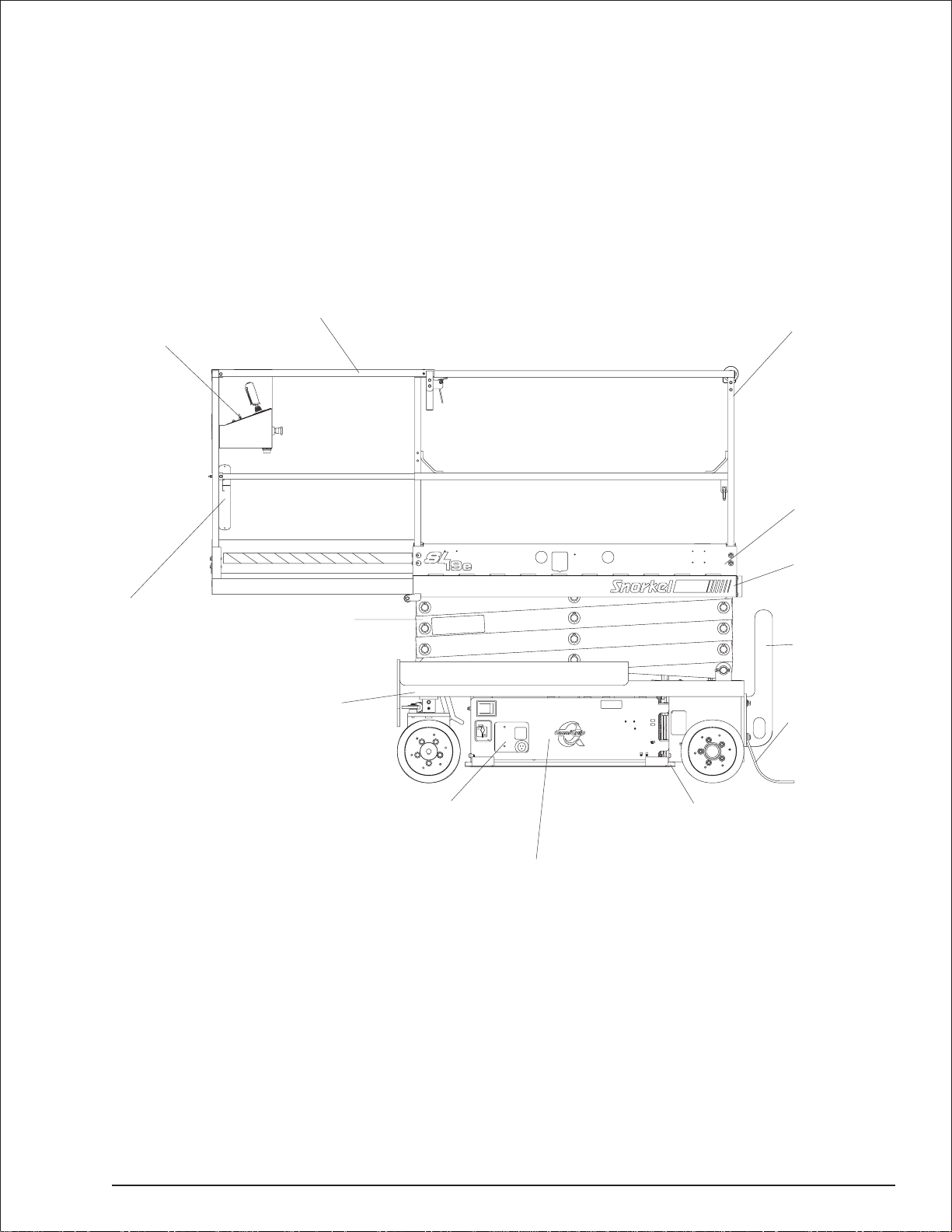
Component Identification
Upper
Controls
Operator’s
Manual Holder
Platform Extension
Scissors
Structure
Chassis
Guardrails
Toeboards
Platform
Entry Step
Ground Strap
Front
Lower
Controls
HydraulicTrayonRightSide
Battery Tray on Left Side
S1930 – 0361266 2-1
Pothole
Protector Skid
Rear

Chapter 2. Specifications
General Specifications
Aerial Platform
Working height 25′ (7.6 m)
Maximum platform height 19′ (5.8 m)
Turning radius (Right turn)
Inside 5.0″ (12.7 cm)
Outside 64.5″ (1.64 m)
Wheelbase 4′ 6″ (1.37 m)
Ground clearance
Pothole protector raised 2.5″ (6.3 cm)
Pothole protector lowered 0.75″ (1.9 cm)
Maximum wheel load 1,416 lbs (642 kg)
Maximum floor pressure 175 psi (12.3 kg/cm²)
Weight, GVW
Approximate 3,040 lbs (1,379 kg)
Stowed width 30″ (76.2 cm)
Stowed length 6′ 2″ (1.9 m)
With step removed 5′ 6″ (1.7 m)
Stowed height 6′ 7″ (2.0 m)
Platform
Dimensions
Main 29″ x 61.5″ (74 cm x 156 cm)
Extension 24″ x36″ (61.0 cm x 91.4 cm)
Guardrail height
Main 39″ (1.0 m)
Extension 39″ (1.0 m)
Toeboard height 6″ (15.2 cm)
Rated work load
Total 500 lb (227 kg)
Extension 250 lb (113 kg)
Maximum number of occupants 2 people
AC outlet 120 V, 17.4 amp
Function Speed
Platform raise 12 to 20 seconds
Platform lower 20 to 26 seconds
Drive
Platform raised less than 7′ (2.1 m)
0 to 2 mph (0.6 to 3.2 km/h)
Platform raised more than 7′ (2.1 m)
0 to 0.4 mph (0 to 0.6 km/h)
Drive System
Standard 2-wheel dr ive
Gradeability 20%
Drive/Lift Level Sensor Interlock
Side to side 2°
Front to rear 4°
Tires
Solid r ubber 4″ x12″ (10.2 cm x 30.5 cm)
Electrical System
Voltage 24 V DC negative chassis ground
Source 4-6 V 220 amp hour batteries
Fluid recommended distilled water
Hydraulic System
Maximum pressure 2,800 psi (19,305 kPa)
Reservoir capacity 3 US gal (11.4 l)
System capacity 3.5 US gal (13.2 l)
Maximum operating temperature 160°F (71°C)
Hydraulic fluid recommended
Above 10°F (-13°C) Mobil DTE-13M (ISO VG32)
Below 10°F (-13°C) Mobil DTE-11M (ISO VG15)
Ambient Air Temperature Operating Range
Fahrenheit 0°F to 110°F
Celsius -18°C to 43°C
2-2 S1930 – 0361266

Chapter 3. Safety
Knowledgeoftheinformationinthismanual,andproper
training, provide a basis for safely operating the aerial
platform.Know the location of all controls and howthey
operatetoactquicklyandresponsiblyin anemergency.
Safety devices reduce the likelihood of an accident.
Never disable, modify, or ignore any safety device.
Safety alerts in this manual indicate situations where
accidents may occur.
If any malfunction, hazard or potentially unsafe condi
tionrelatingtocapacity,intended use, orsafeoperation
is suspected, stop aerial platform operation and seek
assistance.
The operator bears ultimate responsibility for following
all manufacturer’s instructions and warnings, regula
tionsandsafetyrulesoftheir employerand/orany state
or federal law.
Electrocution Hazards
Theaerialplatform ismadeof metalcomponentsand is
not insulated. Regard all conductors as energized. Do
not operate outside during a thunderstorm.
Minimum Safe Approach Distance
Minimum safe approach distances to energized power
linesandtheir associatedpartsmustbeobservedwhile
operating the aerial platform.
ADANGER
The aerial platform is not electrically insulated.
Deathor seriousinjurycan resultfromcontactwith,
or inadequate clearance from, an energized con
ductor.Do not go closer than the minimumsafeap
proach distance as defined by ANSI.
ANSI publications define minimum distances that must
be observed when working near bus bars and ener
gized power lines. Table 1 and Figure 3 are reprinted
courtesy of Scaffold Industry Association, ANSI/SIA
A92.6, page 36.
-
Voltage range
(phase to phase)
0 to 300V
Over 300V to 50kV
Over 50kV to 200kV
Over 200kV to 350kV
Over 350kV to 500kV
Over 500kV to 750kV
Over 750kV to 1000kV
Table 1—Minimum Safe Approach Distance
Minimum safe approach distance
(Feet) (Meters)
Avoid contact
10
15
20
25
35
45
-
-
-
3.05
4.60
6.10
7.62
10.67
13.72
Figure 3—Minimum Safe Approach Distance
S1930 – 0361266 3-1

Chapter 3. Safety
Prestart Inspection
Perform a prestart inspection before each shift as de
scribed in Chapter 8. Do not use the aerial platform on
thejob unlessyouaretrainedandauthorizedto doso.
Work Place
Inspection and Practices
Do not use the aerial platform as a ground connection
when welding. The welding ground clamp must be at
tachedtothe same structure thatisbeing welded.Elec
trical current flowcan be very intense, causingserious
internal damage to some components.
Inspect the area beforeand during aerial platform use.
Thefollowingaresomepotentialhazards thatmaybein
the work place.
●
Debris
●
Slopes
●
Drop-offs or holes
●
Bumps and floor obstructions
●
Overhead obstructions
●
Unauthorized persons
●
High voltage conductors
●
Wind and weather conditions
●
Inadequate surface and support to withstand load
forcesappliedby theaerialplatformin all operating
configurations
Beforeusing the aerial platforminany hazardous (classified) location, make certain it is approved and of the
typerequiredbyANSI/NFPA 505foruse in thatparticu
lar location.
Know and understand the job site traffic-flow patterns and
obey the flagmen, road signs, and signals.
While operatingtheaerialplatform,agoodsafety prac
ticeistohavequalifiedpersonnelinthe immediatewor k
area to:
●
Help in case of an emergency
●
Operate emergency controls as required
●
Watch for loss of control by platform operator
●
Warn the operator of any obstructions or hazards
that may not be obvious to them
●
Watch for soft terrain, sloping surfaces, drop-offs,
etc. where stability could be jeopardized
●
Watchfor bystandersandnever allowanyonetobe
under, or to reach through the scissors structure
while operating the aerial platform
-
Pinch points may exist between moving compo
ADANGER
nents. Death or serious injury can result from be
coming trapped between components, buildings,
structures, or other obstacles. Make sure there is
sufficient clearance around the machine before
moving the chassis or platform. Allow sufficient
room and time to stop movement to avoid contact
-
with structures or other hazards.
Always look in the direction of movement. Drive with
careandat speeds compatiblewith the workplacecon
ditions.Usecautionwhendrivingoverrough ground,on
slopes,andwhenturning.Do not engage inanyform of
horseplay or permit riders any place other than in the
platform.
Secureallaccessories,containers,tools,and otherma
terials in the platform to preventthemfromaccidentally
falling or being kicked off the platform. Remove all ob
jects that do not belong in or on the aerial platform.
Never steady the platform by positioning it against an
other platform.Do not use boards, or other temporary
means to support or level the aerial platform.
Donotoperate the aerialplatformif it isdamagedor not
functioning properly. Qualified maintenance personnel
must correct the problembeforeputting the aerial platform back into service.
Operation
Usethreepoints of support whenenteringorexitingthe
platform. For example, use two hands and one foot
-
when climbing into the platform.
Makesure theareabelow theplatform isfreeof person
nel before lowering.
Keep both feet positioned firmly on the platform floor.
-
Operate the controls slowly and deliberately to avoid
jerky and erratic operation. Always stop the controls in
neutral before going in the opposite direction.
Donotdismount while theaerialplatformis in motionor
jump off the platform.
Properly stow the aerial platform and secure it against
unauthorizedoperationat theendof eachworkday,be
fore transporting, or if it is left unattended.
Tip-Over and Falling Hazards
Operatetheaer ial platform onlyona firm, flat, level sur
facecapableof withstanding all load forcesimposedby
the aerial platform in all operating conditions. Refer to
the General Specifications chart for the maximum
wheel load, maximumfloorpressure,and drive/lift level
sensor interlock information. Raise the platform only
when the aerial platform is on level ground.
-
-
-
-
-
-
-
-
-
3-2 S1930 – 0361266

Chapter 3. Safety
ADANGER
The aerial platformcan tip over if it becomesunstable.
Death or serious injury can result from a tip-overacci
dent.Donotdriveorpositiontheaerialplatf ormforele
vateduse nearan ydrop-off,hole,slope,softor uneven
ground, or other tip-over hazard.
Do not operate the aerial platform within 4 (1.2 m) of
any drop-off or hole.
It isbestnotto transfer fromtheplatformtoanother struc
tureorfrom the structuretotheplatform, unlessthatis the
safest way to do the job.Judge each situation separately
takingthe workenvironment intoaccount.If itisnecessary
to transf er from the platform to another structure the fol
lowing guidelines apply:
1. Ifyou areusinga fallrestraint, transferyouranchor
age fromonestructuretothe other beforestepping
across.
2. Remember that you might be transf erring to a struc
ture where
3. Use the platform entrance, do not climb over the
guardrails.
Donotraise theplatformoutdoors or inthewind.Donot
addanythingtothe aerial platform that willincreasethe
wind loading such as billboards, banners, flags, etc.
Never operate the aerial platform without all parts of the
guardrail system in place and the safety chain or gate
closed.Makesure thatallprotectiveguards,cowlings,and
doors are securely fastened.
Donotexceed theplatformcapacity as indicatedonthe
platform rating placard on the platform. Do not carry
loads that extend beyond the platform guardrails without
prior written consent from Snorkel.
Do not operate the aerial platform from trucks, trailers,
railway cars, floating vessels, scaffolds, or similar
equipment unless the application is approvedinwriting
by Snorkel.
Do not usetheaerialplatformasacrane, hoist, jack,or
for anypurpose other than to position personnel, tools,
and materials.
Donotclimb ontheguardrails oruseladders, planks,or
other devices to extend or increase the work position
from the platform.
Take caretopre v entrope, electrical cords,andhoses, etc.,
from becoming caught in or on the aerial platform. If the
platform orscissorsstructurebecomescaughtonanadja
cent structure or other obstacle and is preventedfromnor
mal motion, reverse the control to free the platform. If
control reversal does not free the platform, evacuate the
platform before attempting to free it.
personal fall arrest
is required.
Electrical System
Charge the batteries in a well-ventilated area free of
flame, sparks, or other hazards that might cause fire or
-
explosion.
-
Donotoperateanyoftheaerialplatform functionswhile
the battery charger is plugged in.
ADANGER
Batteries give off hydrogen and oxygen that can
combineexplosively.Deathor seriousinjury canre
-
sult from a chemical explosion. Do not smoke or
permit open flames or sparks when checking the
batteries.
-
Battery acidcan damage theskinand eyes.Serious
infection orreactioncan result if medical treatment
-
is not given immediately. Wearfaceandeye protec
tion when working near the batteries.
Batteries contain sulfuric acid that can damage your
-
eyes or skin on contact. Wear a face shield, rubber
gloves, and protective clothing when wor king around
batteries. If acid contacts your eyes, flush immediately
with clear water and get medical attention. If acid contacts your skin, wash off immediately with clear water.
Hydraulic System
The hydraulic system contains hoses with hydraulic
fluid under pressure.
ADANGER
Hydraulic fluid escaping under pressure can have
enough force to inject fluid into the flesh. Serious
infection orreactioncan result if medical treatment
is notgivenimmediately.In caseofinjuryby escap
inghydraulic fluid,seekmedical attentionat once.
Do not place yourhandoranypart of yourbodyinfront
of escaping hydraulicfluid.Use a piece of cardboard or
wood to search for hydraulic leaks.
Placards and Decals
The aerial platform is equipped with placards and de
cals that provide instruction for operation and accident
prevention. Do not operate the aerial platform if any
placards or decals are missing or not legible.
-
-
-
-
-
-
S1930 – 0361266 3-3

Chapter 4. Safety Devices
This aerial platform is manufactured with safety de
vices, placards, and decals to reduce the likelihood of
an accident. For the safety of all personnel, do not dis
able,modify,orignoreanysafetydevice.Safetydevices
are included in the daily prestart inspection.
ADANGER
Thepotentialfor anaccidentincreases whensafety
devices do not function properly. Death or serious
injury can result from such accidents. Do not alter,
disable, or override any safety device.
If any safety devices are defective, remove the aerial
platform from service until qualified maintenance per
sonnel can make repairs.
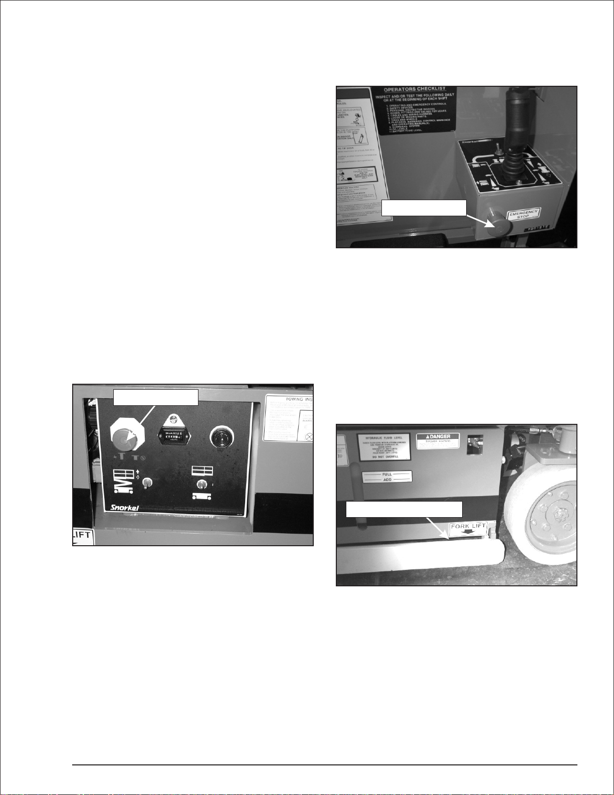
Emergency Stop Controls
Thereisan emergencystopcontrol atthelowerandup
per controls.
At the lower controls, the emergency stop is a
two-position push button (refer to Figure 4.1).
Pushtheemergency stopbuttonin todisconnectpower
to all control circuits. Pull the button out to restore
power.
Emergency Stop
-
-
Emergency Stop
-
Figure 4.2—Upper Controls
Drive Motion Alarm
-
Whenthe joystickismovedout ofneutral todr ivetheae
rial platform, the alarm emits a loud beeping sound to
warn personnel in the work area to stand clear.
Pothole Protector Skids
The pothole protector skids automatically lower when
the platform is elevated approximately 24″ (61 cm).
Ground clearance is reduced from 2
(1.9 cm) when the skids lockinto position (refer to Figure 4.3).
1
″ (6.3 cm)
/2
to
-
3
/4″
Pothole Protector Skid
Figure 4.1—Lower Controls
Note
The lower controls override the upper controls. If the
upper control emergency stop button is engaged, the
lower controls can still be used to operate the aerial
platform.
At the upper controls, the emergency stop is a
two-position push button (refer to Figure 4.2).
Pushtheemergency stopbuttonin todisconnectpower
to the upper control circuits. Pull the button out to re
store power.
S1930 – 0361266 4-1
The aerialplatformcan tip over ifitbecomesunsta
ble. Death or serious injury can result from a
tip-overaccident.Do notdriveor position the aerial
platform for elevated use within four feet of any
-
drop-off, hole, or other tip-over hazard.
This protection system limits the tilt angle if a wheel is
driven into a drop-off or hole. This greatly reduces the
likelihood of the aerial platform tipping over.
The pothole protection system is for added protection
and does not justify operating near drop-offs or holes.
Figure 4.3—Pothole Protector Skids
ADANGER
-
Chapter 4. Safety Devices
Drive/Lift Pothole
Protector Interlock
The aerial platform drive and lift functions are inter
lockedthrough a limit switchthatsenses whether ornot
the pothole protection linkage is locked into position.
The drive/lift pothole interlock operates when the plat
form is elevated approximately 7′ (2.1 m).
If an obstruction under the skids, or some other impair
ment prevents the skids from locking into position, the
driveandliftfunctionswill not operate and an alarm will
sound.
Lower the platform and remove the obstruction when
the drive/lift pothole protector interlock alarm sounds.
Drive/Lift Level Sensor Interlock
The aerial platform drive and lift functions are inter
lockedthrough alevelsensorsystem.The drive/liftlevel
sensorinterlockoperateswhen theplatformiselevated
approximately 7′ (2.1 m).
Ifthechassis istiltedmorethan2degreesside-to-sideor
morethan4 degreesfront-to-rear, thedriveandlift func
tions will not operate and an alarm will sound.
Lowerthe platformanddriveto alevelsurfacewhenthe
drive/lift level sensor alarm sounds.
Thedrive/liftlevelsensor systemisforaddedprotection
and does not justify operating on anything other than
firm, flat, level surfaces.
Lowering Alarm
When the joystick is moved out of neutral to lower the
platform,thealarmemitsaloudbeeping sound to warn
personnel in the work area to stand clear.
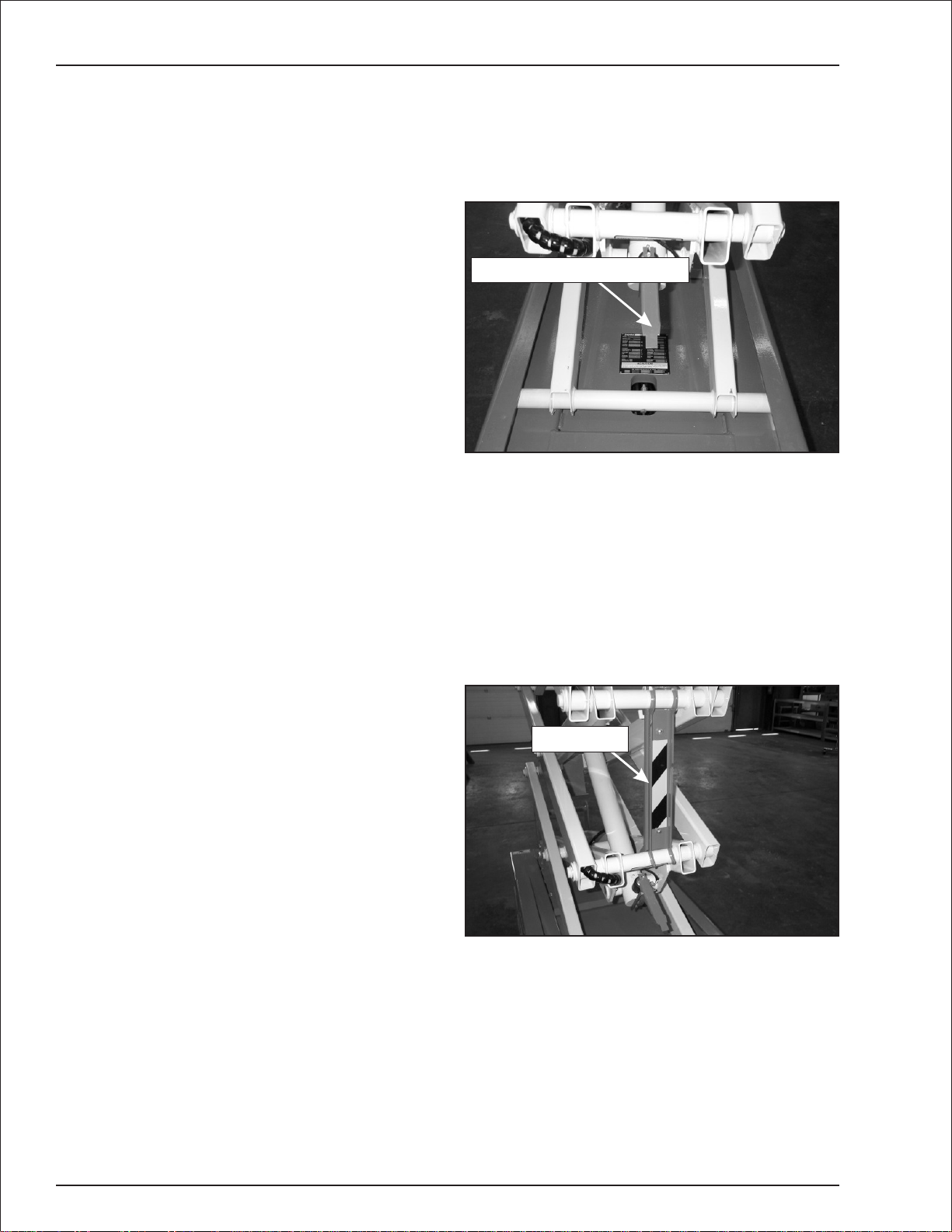
Emergency Lowering Lever
Theemergencyloweringlevermaybeusedto lowerthe
platformifthere isamalfunction inthehydraulicorelec
tricalsystem.Theleverismounted atthe frontofthe ae
rial platform (refer to Figure 4.4).
-
-
Emergency Lowering Lever
-
Figure 4.4—Emergency Lowering Lever
Theemergencyloweringlevermaybeusedto lowerthe
scissorsarmsontothesafetyprop beforeinspectingthe
machine.
Safety Prop
The safety prop (refer to Figure 4.5) is used to support
the scissors structure when access to the scissors arm
components or the chassis is required. Always use the
safety prop when the platform is raised during inspection and maintenance.
Safety Prop
-
-
ADANGER
Pinch points exist on the scissors structure. Death
or seriousinjurycan result if thescissorsstructure
lowers onto personnel within the scissors arms or
under the raised platform.Stand clear while raising
and lowering the platform.
Becarefulwhenlowering the platform.Keephandsand
fingersawayfrom thescissorsstructurescomponents.
Figure 4.5—Safety Prop
4-2 S1930 – 0361266
Chapter 4. Safety Devices
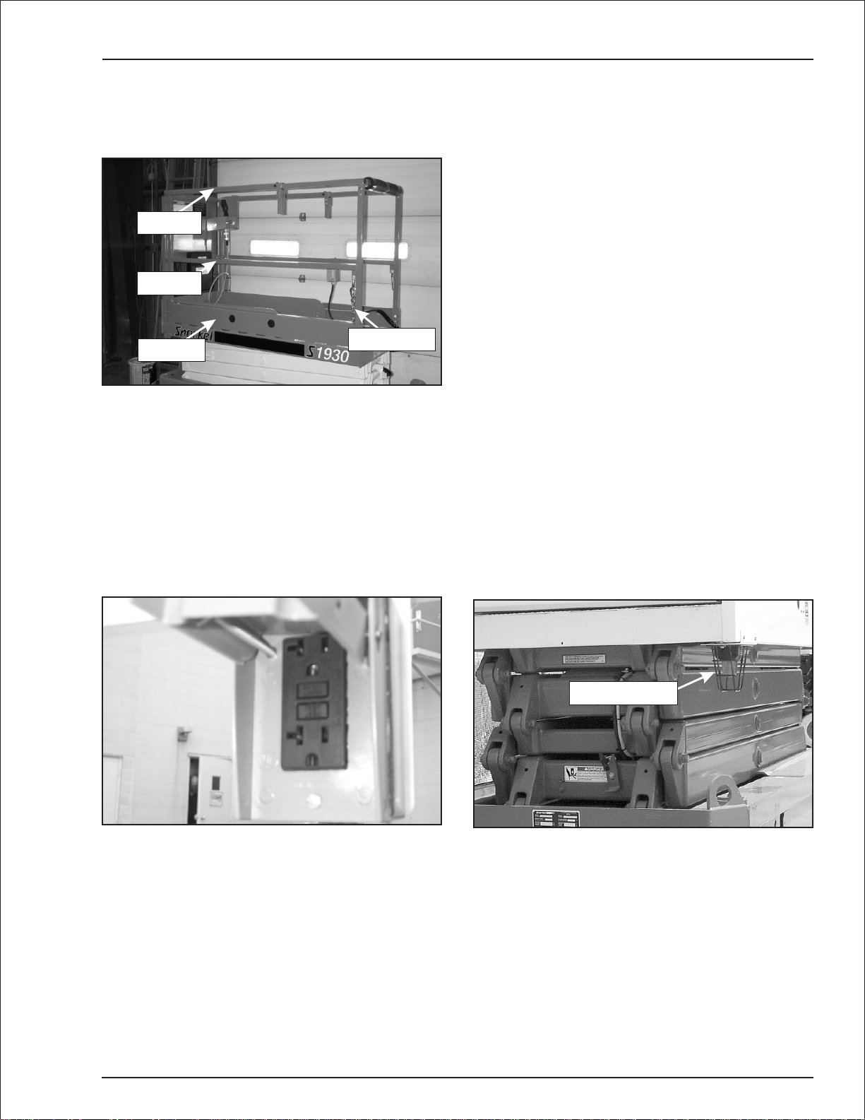
Guardrails
The guardrail system includes a top rail, mid rail, and
toeboardsaroundthesides of theplatform(refer toFig
ure 4.6).
Top Rail
Mid Rail
Toeboard
Figure 4.6—Guardrails
A safety chain or an optional swinging gate allows for
access to the platform. The gates close automatically
after entering or exitingthe platform.The chain or gate
is part of the guardrail system and must be securely
fastened after entering the platform.
Entry Chain
Ground Fault Circuit Interrupter
The electrical power outlet (refer to Figure 4.7), at the
platform contains a ground fault circuit interrupter
(GFCI)to helppreventaccidental conductorgrounding.
Tilt Alarm
An alarm will sound if the aerial platform chassis is out
of level more than 1
raised.
1
/2 degrees when the platform is
ADANGER
The aerialplatformcan tip over ifitbecomesunsta
ble. Death or serious injury can result from a
tip-overaccident.Do notdriveor position the aerial
platform for elevated use near any drop-off, hole,
slope, soft or uneven ground,or other tip-over haz
ard.
Completely lower the platform and then drive to a level
surface when the tilt alar m sounds.
Thetiltalarm isforaddedprotection anddoesnotjustify
operating on anything other than firm, flat, level sur
faces.
Horn
The optional horn may be used to warn personnel on
the ground. The horn is operational when the machine
is set up for operation from the upper controls.
Flashing Light
Anoptional redor amberflashing lightmaybelocatedat
the rear of the aerial platform (refer to Figure 4.9).The
flashinglightwarnspersonnel that the aerial platformis
in the area.
-
-
-
Flashing Light
Figure 4.7—Electrical Power Outlet
The light flashes at about one flash per second when
the machine is set up for operation from the upper con
trols.
S1930 – 0361266 4-3
Figure 4.9—Flashing Light
-

Chapter 5. Gauges
The aerial platform is equipped with several gauges to
monitor the condition of the machine before and during
operation.
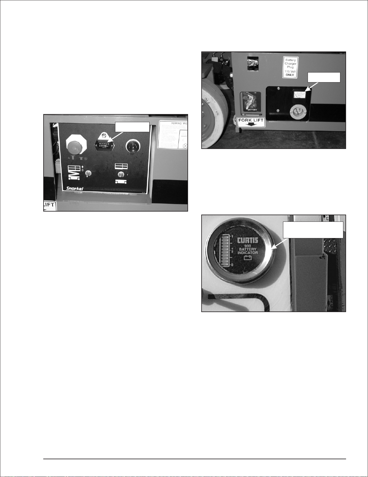
Hour Meter
Thehourmeterislocated onthe lowercontrol panel(re
fer to Figure 5.1). It measures the accumulated aerial
platform operating time.
Hour Meter
Figure 5.1—Lower Controls
Ammeter
The ammeter is located on the battery charger (refer to
Figure 5.2). When the batteries are charging, the ammeterdisplaysthe levelof current flowfromthe charger
to the batteries.
Ammeter
-
Figure 5.2—Battery Charger
Battery Condition Indicator
The optional battery conditionindicator (refer to Figure
5.3)islocated ontheupper control panel.Itdisplaysthe
level of available battery power to operate the aerial
platform. The number one on the scale indicates full
power and zero indicates no power.
Battery
Condition Indicator
Figure 5.3—Battery Condition Indicator
SL 19e – 0361265 5-1
 Loading...