


 Loading...
User Manual
August 2009
ZEESCGB316B Rev. A

Trademarks
Snap-on, Sun, SOLUS, and Scanner are trademarks of Snap-on Incorporated, registered in the United States and other countries.
All other marks are trademarks or registered trademarks of their respective holders.
Copyright Information
©2009 Snap-on Incorporated. All rights reserved.
Disclaimer of Warranties and Limitation of Liabilities
The information, specifications and illustrations in this manual are based on the latest information available at the time of printing. While the authors have taken due care in the preparation of this manual, nothing contained herein:
•Modifies or alters in any way the standard terms and conditions of the purchase, lease, or rental agreement under the terms of which the equipment to which this manual relates was acquired.
•Increases in any way the liability to the customer or to third parties.
Snap-on reserves the right to make changes at any time without notice.
IMPORTANT:
Before operating or maintaining this unit, please read this manual carefully paying extra attention to the safety warnings and precautions.
Visit our websites at:
snapon.com (North America)
snapondiag.com (United Kingdom)
sun-diagnostics.com (United Kingdom)
For Technical Assistance Call
1-800-424-7226 (North America)
CALL +44 (0) 845 601 4736 (United Kingdom)
E-mail DiagnosticsUKproductsupport@snapon.com (United Kingdom)
For technical assistance in all other markets, contact your selling agent.
ii

Safety Information
For your own safety and the safety of others, and to prevent damage to the equipment and vehicles upon which it is used, it is important that these Safety Messages be read and understood by all persons operating, or coming into contact with, the equipment.
This product is intended for use by properly trained and skilled professional automotive technicians. The safety messages presented throughout this manual are reminders to the operator to exercise extreme care when using this test instrument.
There are many variations in procedures, techniques, tools, and parts for servicing vehicles, as well as in the skill of the individual doing the work. Because of the vast number of test applications and variations in the products that can be tested with this instrument, we cannot possibly anticipate or provide advice or safety messages to cover every situation. It is the automotive technician’s responsibility to be knowledgeable of the system being tested. It is essential to use proper service methods and test procedures. It is important to perform tests in an appropriate and acceptable manner that does not endanger your safety, the safety of others in the work area, the equipment being used, or the vehicle being tested.
It is assumed that the operator has a thorough understanding of vehicle systems before using this product. Understanding of these system principles and operating theories is necessary for competent, safe and accurate use of this instrument.
Before using the equipment, always refer to and follow the safety messages and applicable test procedures provided by the manufacturer of the vehicle or equipment being tested. Use the equipment only as described in this manual.
Read, understand and follow all safety messages and instructions in this manual, the accompanying safety manual, and on the test equipment.
Safety Message Conventions
Safety messages are provided to help prevent personal injury and equipment damage. All safety messages are introduced by a signal word indicating the hazard level.
! DANGER
Indicates an imminently hazardous situation which, if not avoided, will result in death or serious injury to the operator or to bystanders.
! WARNING
Indicates a potentially hazardous situation which, if not avoided, could result in death or serious injury to the operator or to bystanders.
! CAUTION
Indicates a potentially hazardous situation which, if not avoided, may result in moderate or minor injury to the operator or to bystanders.
iii

Safety Information |
Important Safety Instructions |
Safety messages contain three different type styles.
•Normal type states the hazard.
•Bold type states how to avoid the hazard.
•Italic type states the possible consequences of not avoiding the hazard.
An icon, when present, gives a graphical description of the potential hazard.
Example:
! WARNING
Risk of unexpected vehicle movement.
• Block drive wheels before performing a test with engine running.
A moving vehicle can cause injury.
Important Safety Instructions
For a complete list of safety messages, refer to the accompanying safety manual.
SAVE THESE INSTRUCTIONS
iv

Contents
Safety Information ..................................................................................................................... |
iii |
Contents ...................................................................................................................................... |
v |
Chapter 1: Using This Manual ................................................................................................... |
1 |
Conventions.................................................................................................................................. |
1 |
Bold Text................................................................................................................................ |
1 |
Symbols ................................................................................................................................. |
1 |
Terminology ........................................................................................................................... |
2 |
Notes and Important Messages ............................................................................................. |
2 |
Procedures............................................................................................................................. |
2 |
Additional Manuals ....................................................................................................................... |
3 |
Chapter 2: Introduction.............................................................................................................. |
4 |
Functional Description .................................................................................................................. |
4 |
Technical Specifications ............................................................................................................... |
6 |
The Stand ..................................................................................................................................... |
7 |
Control Buttons............................................................................................................................. |
8 |
N/X Button.............................................................................................................................. |
9 |
Y/a Button.............................................................................................................................. |
9 |
Thumb Pad ............................................................................................................................ |
9 |
Brightness/Contrast Button .................................................................................................... |
9 |
S Button ................................................................................................................................. |
9 |
Power Button ......................................................................................................................... |
9 |
Connections................................................................................................................................ |
10 |
DC Power Input.................................................................................................................... |
10 |
Mini USB Port ...................................................................................................................... |
10 |
USB Port .............................................................................................................................. |
10 |
Data Cable Connector ......................................................................................................... |
10 |
Power Supply ............................................................................................................................. |
10 |
Vehicle Power ...................................................................................................................... |
11 |
Battery Pack......................................................................................................................... |
11 |
AC/DC Power Supply........................................................................................................... |
12 |
Cables ........................................................................................................................................ |
12 |
Data Cable ........................................................................................................................... |
13 |
Auxiliary Power Cables ........................................................................................................ |
13 |
Chapter 3: Getting Started....................................................................................................... |
14 |
Demonstration Mode .................................................................................................................. |
14 |
Supplying Power......................................................................................................................... |
15 |
Connecting to Vehicle Power ..................................................................................................... |
15 |
Using the Battery Pack ............................................................................................................... |
16 |
Connecting the AC/DC Power Supply ........................................................................................ |
18 |
Powering On the Unit ................................................................................................................. |
19 |
Setting Up to Print ...................................................................................................................... |
19 |
|
v |

Contents
Connecting to a Computer.......................................................................................................... |
20 |
Powering Off the Unit ................................................................................................................. |
20 |
Adjusting Brightness and Contrast ............................................................................................. |
20 |
Chapter 4: Navigation .............................................................................................................. |
22 |
Screen Layout ............................................................................................................................ |
22 |
Upper Toolbar ...................................................................................................................... |
22 |
Buffer Bar............................................................................................................................. |
24 |
Main Body ............................................................................................................................ |
24 |
LED Indicators ..................................................................................................................... |
25 |
Status Bar ............................................................................................................................ |
25 |
Making Selections ...................................................................................................................... |
25 |
Using Easy Scroll ....................................................................................................................... |
26 |
Screen Messages....................................................................................................................... |
26 |
Confirmation Messages.............................................................................................................. |
26 |
Warning Messages..................................................................................................................... |
26 |
Error Messages .......................................................................................................................... |
26 |
Chapter 5: Operations.............................................................................................................. |
27 |
Selecting the Manufacturer......................................................................................................... |
28 |
Identifying the Vehicle ................................................................................................................ |
28 |
Selecting a System..................................................................................................................... |
29 |
Connecting to a Vehicle.............................................................................................................. |
29 |
Selecting from the System Main Menu....................................................................................... |
30 |
Using the Scanner Functions ..................................................................................................... |
30 |
Data Display......................................................................................................................... |
31 |
Codes Menu......................................................................................................................... |
31 |
Functional Tests................................................................................................................... |
33 |
Generic Functions................................................................................................................ |
33 |
Terminating Vehicle Communication ................................................................................... |
34 |
Exiting Scanner Mode.......................................................................................................... |
34 |
Viewing Data Graphically ........................................................................................................... |
34 |
Changing Screen Views....................................................................................................... |
34 |
PID List View........................................................................................................................ |
35 |
Text View ............................................................................................................................. |
38 |
Graph View .......................................................................................................................... |
38 |
Pausing Data ....................................................................................................................... |
43 |
Clearing the Data Buffer ...................................................................................................... |
43 |
Sorting the Data ................................................................................................................... |
43 |
Using Cursors ...................................................................................................................... |
44 |
Using Zoom.......................................................................................................................... |
44 |
Saving Captured Data ................................................................................................................ |
45 |
Viewing Saved Data ................................................................................................................... |
47 |
Identifying Saved Files......................................................................................................... |
48 |
Loading Saved Files ............................................................................................................ |
49 |
Editing Saved Data .............................................................................................................. |
49 |
Reviewing Saved Data......................................................................................................... |
49 |
Deleting Saved Files ............................................................................................................ |
50 |
Copying and Moving Saved Data ........................................................................................ |
50 |
Selecting All Files................................................................................................................. |
51 |
vi

Contents
Viewing Saved Data Information.......................................................................................... |
51 |
Setting a Destination for Saved Data................................................................................... |
52 |
Printing ....................................................................................................................................... |
52 |
Tools Button ............................................................................................................................... |
53 |
Custom Setup ...................................................................................................................... |
53 |
Save Data ............................................................................................................................ |
54 |
Custom Data List ................................................................................................................. |
54 |
LED Setup............................................................................................................................ |
55 |
Utilities ........................................................................................................................................ |
55 |
Tool Setup............................................................................................................................ |
56 |
System Tools ....................................................................................................................... |
61 |
Easy Scroll ........................................................................................................................... |
61 |
Connect to PC...................................................................................................................... |
62 |
Run ...................................................................................................................................... |
62 |
Shop Info.............................................................................................................................. |
62 |
System Info .......................................................................................................................... |
63 |
Chapter 6: Maintenance ........................................................................................................... |
64 |
Cleaning and Damage Inspection .............................................................................................. |
64 |
Battery Pack ............................................................................................................................... |
64 |
Replacing the Battery Pack.................................................................................................. |
64 |
Storage Tips ............................................................................................................................... |
64 |
Disposing of the Battery Pack .................................................................................................... |
65 |
Replacing the Display Window ................................................................................................... |
65 |
Appendix A: Frequently Asked Questions............................................................................. |
66 |
Can I use my other Snap-on® test adapters with this scan tool?............................................... |
66 |
What should I do if my printer is not responding? ...................................................................... |
66 |
What should I do if the unit doesn’t respond as expected when I press the Power button? ...... |
66 |
Why does my unit shut down unexpectedly? ............................................................................. |
67 |
Appendix B: Troubleshooting ................................................................................................. |
68 |
No Communication Message ..................................................................................................... |
68 |
Battery Pack Not Charging ......................................................................................................... |
68 |
Unit Will Not Power On............................................................................................................... |
69 |
Forced Shutdown ....................................................................................................................... |
69 |
Beep Codes................................................................................................................................ |
69 |
Appendix C: Downloading and Installing Software Updates ............................................... |
70 |
Check for Service Upgrades Before Use.................................................................................... |
70 |
Verifying Minimum PC Requirements......................................................................................... |
70 |
Verifying PC System Properties........................................................................................... |
71 |
Downloading and Installing ShopStream Connect ..................................................................... |
71 |
Downloading Service Upgrades ................................................................................................. |
73 |
Before You Begin................................................................................................................. |
74 |
Installing a Service Upgrade ................................................................................................ |
74 |
Index .......................................................................................................................................... |
77 |
vii

Chapter 1 Using This Manual
This manual contains tool usage instructions.
Some of the illustrations shown in this manual may contain modules and optional equipment that are not included on your system. Contact your sales representative for availability of other modules and optional equipment.
1.1 Conventions
The following conventions are used.
1.1.1 Bold Text
Bold emphasis is used in procedures to highlight selectable items such as buttons and menu options.
Example:
•Press the Y/a button.
1.1.2Symbols
Different types of arrows are used.
The “greater than” arrow (>) indicates an abbreviated set of selection instructions.
Example:
• Select Utilities > Tool Setup > Date.
The example statement abbreviates the following procedure:
1.Navigate to the Utilities button.
2.Use the Thumb Pad to navigate to and highlight the Tool Setup submenu.
3.Use the Thumb Pad to navigate to and highlight the Date option from the submenu.
4.Press Y/a to confirm the selection.
The solid arrows (e, c, d, b) are navigational instructions referring to the four directions of the Thumb Pad.
Example:
• Press the down d arrow.
1

Using This Manual |
Conventions |
1.1.3 Terminology
The term “select” means highlighting a button or menu item using the Thumb Pad and pressing the Y/a button to confirm the selection.
Example:
• Select Reset.
The above statement abbreviates the following procedure:
1.Navigate to and highlight the Reset button.
2.Press the Y/a button.
1.1.4Notes and Important Messages
The following messages are used.
Notes
A NOTE provides helpful information such as additional explanations, tips, and comments.
Example:
NOTE:
i For additional information refer to...
Important
IMPORTANT indicates a situation which, if not avoided, may result in damage to the test equipment or vehicle.
Example:
IMPORTANT:
Do not force the CompactFlash® card into the slot.
1.1.5 Procedures
An arrow icon indicates a procedure.
Example:
zTo change screen views:
1.Select the View button.
The drop-down menu displays.
2.Select an option from the menu.
The screen layout changes to the format you selected.
2

Using This Manual |
Additional Manuals |
1.2 Additional Manuals
This tool works in conjunction with other software products. All of the required manuals are included on the Diagnostic User Documentation CD, which was supplied with your scan tool kit. See the appropriate manual for information regarding these products.
3
Chapter 2 Introduction
The scan tool uses Vehicle Communication Software to provide vehicle-specific trouble codes for various vehicle control systems such as engine, transmission, antilock brake system (ABS) and more, selected functional tests, and troubleshooting information. The scan tool can also graph live data parameters on-screen.
Figure 2-1 SOLUS PRO™
2.1 Functional Description
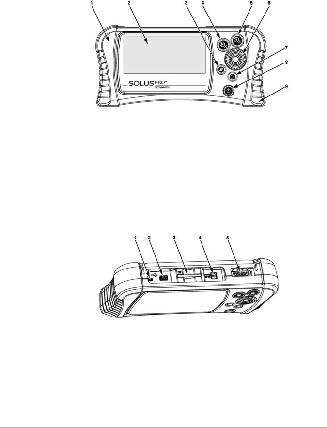
Figure 2-2, Figure 2-3, and Figure 2-4 show the external features of the scan tool.
4
Introduction |
Functional Description |
1— Left handgrip
2— Liquid Crystal Display (LCD) 3— S button
4— N/X (No) button 5— Y/a (Yes) button
6— Thumb Pad
7— Brightness/Contrast button 8— Power button
9— Right handgrip
Figure 2-2 Front view
1— Mini USB port 2— USB port
3— CompactFlash® (CF) Card Slot 4— DC power supply input
5— Data cable connector
Figure 2-3 Top view
5

Introduction |
Technical Specifications |
1— Stand
2— Casing hook
Figure 2-4 Back view
2.2 Technical Specifications
Display:
Liquid Crystal Display (LCD) 640 x 240 resolution
256 colors
6.2 inches (157.5 mm)
CompactFlash ® Card Slot:
The data storage CF card
IMPORTANT:
Never remove the CF card while saving data. Doing so will result in lost data.
Battery Pack:
Nickel-metal hydride Rechargeable Weight:
15.4 oz
437 g
External Battery Charger:
Input: 14.5–15.5 VDC, 18 watts
Output: 0–12 VDC, 1.5A
AC/DC Power Supply:
Input: 100–240 VAC @ 0.5A, 47–63 Hz
Output: 12 VDC @ 1.2A
6

Introduction |
The Stand |
Weight:
With battery pack: 3.37 lbs
1528 g
Dimensions:
Width:
11.85 inches
301 mm Height:
5.63 inches
143 mm Depth:
2.56 inches
65 mm
Operating Temperature Range:
14 to 104°F -10 to 40°C
Storage Temperature Range:
-4 to 149°F -20 to 65°C
Communication Protocols
Your SOLUS PRO™ scan tool supports the following OBD-II/EOBD communications protocols: SAE J1850 (VPW)
SAE J1850 (PWM) ISO 9141-2
ISO 14230-4 (KWP 2000) ISO 15765-4 (CAN)
In addition, the vehicle communications software allows you to access “enhanced” diagnostic information for specific North American, Japanese, and Korean vehicle manufacturers.
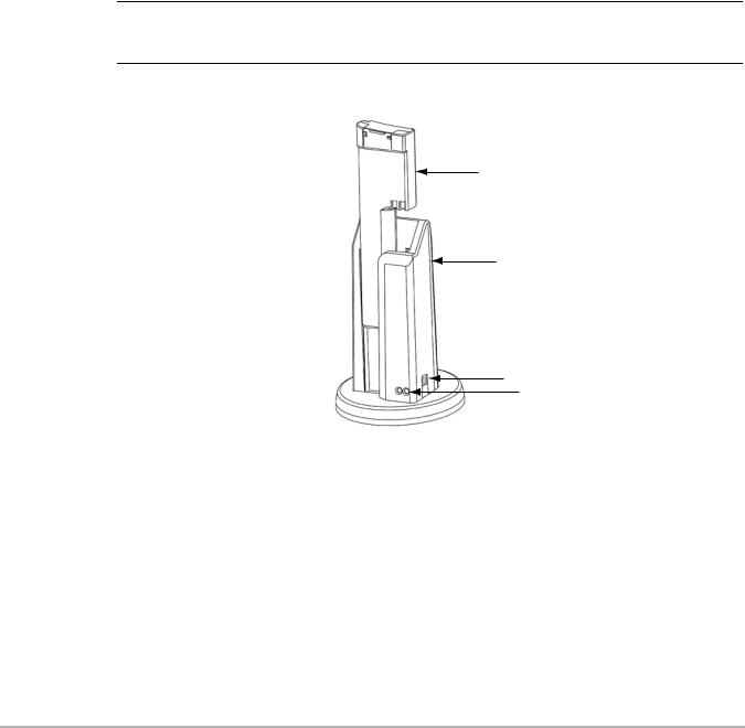
2.3 The Stand
The scan tool has a built-in, metal stand attached to the back. When the stand is not in use, it is secured to the back of the unit by an integrated casing hook (Figure 2-4 on page 6).
When extended, the stand allows the unit to rest at a 45° angle for hands-free viewing (Figure 2-5).
7

Introduction |
Control Buttons |
Figure 2-5 Stand extended
The stand can also be extended to a hanging position by pressing the left side towards the right and rotating forward (Figure 2-6).
Figure 2-6 Stand in hanging position
2.4 Control Buttons
This scan tool has the following control buttons (Figure 2-2 on page 5):
•No (N/X) button
•Yes (Y/a) button
•Thumb Pad
•Brightness/Contrast button
•S button
•Power button
8

Introduction |
Control Buttons |
2.4.1 N/X Button
The N/X button is used to do the following:
•To exit a menu or program.
•To close an open list and return to the previous menu.
•To answer “No” when a Yes or No choice is given.
•To return to the main menu.
2.4.2Y/a Button
The Y/a button is used to do the following:
•To select the item you highlighted using the Thumb Pad.
•To answer “Yes” when a Yes or No choice is given.
2.4.3Thumb Pad
The Thumb Pad moves the highlight, allowing vertical and horizontal on-screen movement. The Thumb Pad is typically used in combination with the Y/a and N/X buttons.
2.4.4 Brightness/Contrast Button
The Brightness/Contrast button opens the dialog box that allows you to adjust the screen for optimum viewing. See “Adjusting Brightness and Contrast” on page 20 for details.
2.4.5 S Button
The S button can be customized to perform different functions from the Utilities > Tool Setup menu. See “S Button” on page 59 for details.
2.4.6 Power Button
The Power button powers on and powers off this scan tool. See “Powering On the Unit” on page 19 and “Powering Off the Unit” on page 20 for details.
The Power button is also used to force the scan tool to shut down. This feature should only be used if the tool is not performing correctly, such as the display locks-up or data is not updating.
zTo perform a forced shutdown:
1.Press and hold down the Power button for five seconds.
2.The scan tool sounds a series of beeps, then turns off. The unit can now be restarted.
9

Introduction |
Connections |
2.5 Connections
This scan tool uses the following connections (Figure 2-3 on page 5):
•DC power adapter input
•Mini USB port
•USB port
•Data cable connector
2.5.1DC Power Input
The AC/DC power supply provides power to the scan tool through the DC power input on top of the unit (Figure 2-3 on page 5). For related information, see the following sections:
•“AC/DC Power Supply” on page 12
•“Connecting the AC/DC Power Supply” on page 18
2.5.2Mini USB Port
This scan tool has a Mini USB port for connecting the scan tool to a PC.
2.5.3 USB Port
This scan tool has a USB port for connecting computer peripherals, such as a printer, a keyboard, or a mass storage device.
2.5.4 Data Cable Connector
The connector on the data cable attaches to adapters that in turn attach the scan tool to a vehicle for testing.
For related information, see the following sections:
•“Cables” on page 12
•“Connecting to Vehicle Power” on page 15
2.6Power Supply
This scan tool can receive power from three sources:
•Vehicle power
•Battery pack (rechargable)
•AC/DC power supply
For related information, see “Supplying Power” on page 15.
10
Introduction |
Power Supply |
2.6.1 Vehicle Power
This scan tool can receive 12V vehicle power via the data cable either by itself or in conjunction with the optional auxiliary power cables.
For related information, see the following sections:
•“Data Cable Connector” on page 10
•“Cables” on page 12
•“Connecting to Vehicle Power” on page 15
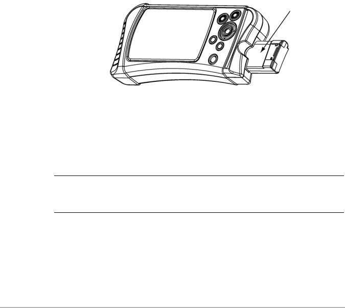
2.6.2Battery Pack
The scan tool can be powered by a rechargeable nickel-metal hydride battery pack installed in the unit behind the right handgrip (Figure 2-7).
Figure 2-7 Battery pack partially removed
The internal battery allows you to power the scan tool, identify the test vehicle, and view the connection message prior to connecting the scan tool to the vehicle. The connection message lets you know which cable adapters and keys are used to connect to the vehicle, and also provides the location of the vehicle data link connector (DLC). Once connected to the vehicle scan tool power must be provided either through the DLC or by the auxiliary power cables when performing vehicle tests or accessing data. A no communication message displays if vehicle power is not available to the scan tool.
IMPORTANT:
A fully-charged battery pack should be installed in the scan tool whenever you are testing a vehicle, even though the scan tool can operate on vehicle power without the battery installed. The battery pack compensates for voltage drops caused by engine cranking.
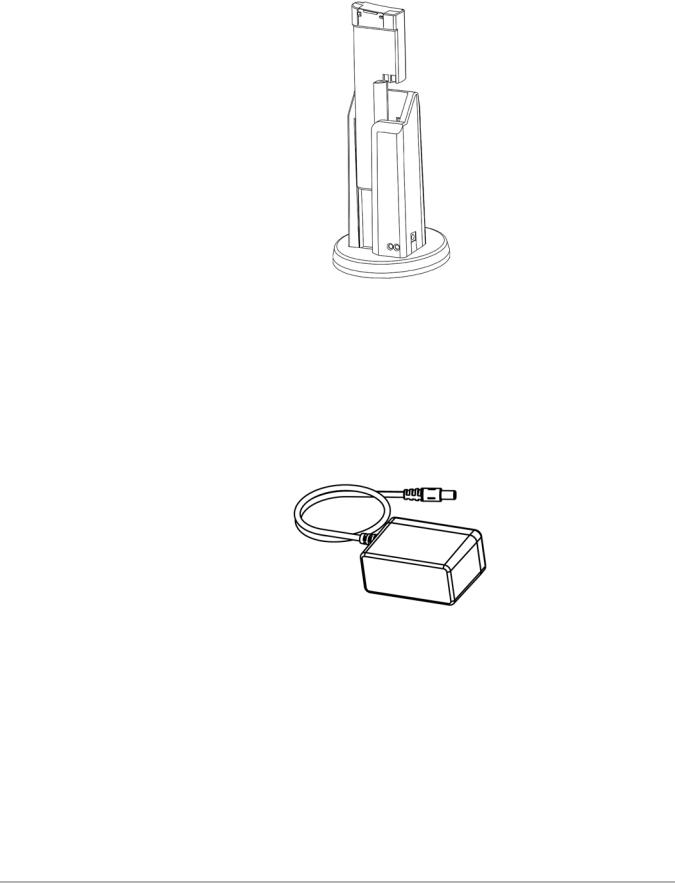
Battery Charger
The battery pack is recharged by an external battery charger (Figure 2-8). See “Using the Battery Pack” on page 16 for information on charging and installing the battery pack.
The battery charger uses the same AC/DC power supply that can also be used to power the scan tool. See “AC/DC Power Supply” on page 12 for more details.
11
Introduction |
Cables |
Figure 2-8 Battery and battery charger
2.6.3 AC/DC Power Supply
This scan tool can be powered from a wall socket using the AC/DC power supply (Figure 2-9). The AC/DC Power Supply provides a constant 12V, and must be used when updating the scan tool software to prevent accidental power loss. The power supply also helps preserve battery life during operations that do not require a connection to the vehicle, such as using Demonstration mode or reviewing and managing saved data files.
Figure 2-9 AC/DC power supply
For related information, see the following sections:
•“DC Power Input” on page 10
•“Connecting the AC/DC Power Supply” on page 18
2.7Cables
This scan tool uses the following cables:
•Data cable
•Auxiliary power cables, lighter and battery, optional.
12
Introduction |
Cables |
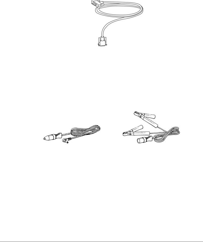
2.7.1 Data Cable
The data cable (Figure 2-10) is included with your scan tool and uses interchangeable test adapters for connecting to vehicle diagnostic connectors.
Figure 2-10 Data Cable
Captive screws secure the data cable ends to the scan tool and test adapter. An optional data cable extension is available.
2.7.2 Auxiliary Power Cables
Two auxiliary power cables, the Lighter Power Cable (Figure 2-11) and the Battery Power Cable (Figure 2-12), are available as an option. The auxiliary cables are used for testing vehicles without battery power on the diagnostic connector.
Figure 2-11 Lighter Power Cable |
Figure 2-12 Battery Power Cable |
Refer to the Accessory Guide, included with your kit, for a complete listing of accessories and replacement parts.
13
Chapter 3 Getting Started
The following steps get you started using the scan tool:
1.Familiarize yourself with SOLUS PRO™ controls and connections. Refer to “Control Buttons” on page 8 for details.
2.Charge the battery. Allow two to three hours for charging. Refer to “Using the Battery Pack” on page 16 for details.
NOTE:
iUse battery power for Vehicle identification purposes only (example: locate the data link connector (DLC) and identify the adapter and keys required for vehicle communication). Always operate your SOLUS PRO™ with the battery pack installed.
3.When fully charged insert the battery pack in the battery slot. See “To install the battery pack:” on page 18 for details.
4.Press the Power button to turn the scan tool on.
Once the tool is powered up, you can use Demonstration mode to become familiar with scan tool navigation and functionality without connecting to a vehicle.
3.1Demonstration Mode
The scan tool contains programs to demonstrate scan tool test capabilities without actually connecting to a vehicle. Sample vehicle data with mock test results are provided to help you become familiar with menus, navigation, and basic operations.
zTo use the EOBD demonstration:
1. Highlight EOBD on the scan tool Main Menu and press Y/a.
Figure 3-1 Global OBD-II/EOBD menu selection
2.Press Y/a to open the EOBD database.
3.Highlight OBD Training Mode and press Y/a.
14

Getting Started |
|
Supplying Power |
|
|
|
|
|
|
Figure 3-2 Sample OBD Training Mode selection
4.Highlight Start Communication on the Main Menu OBD, and Press Y/a to select.
5.Press Y/a when the vehicle connection message displays.
6.The ECU/Protocol Information screen displays, PressY/a to continue.
7.Highlight any of the item on the Select Service menu, and Press Y/a to select. Simulated test data now displays.
8.To exit, press N/X until you return to the Main Menu OBD.
9.Highlight End of Diagnose at the bottom of the list and press Y/a.
10.Highlight the View button on the upper toolbar and press N/X to return to the Main Menu.
3.2 Supplying Power
There are three ways to supply power to the scan tool:
•Connect to vehicle power
•Use the battery pack
•Connect to an AC adapter
For related information, see “Power Supply” on page 10.
NOTE:
iTo extend the life of your battery pack, always power the scan tool with vehicle power or use the AC/DC Power Supply. The battery pack is intended to be used during the vehicle identification process and to get vehicle connection information.
3.3Connecting to Vehicle Power
You need the following to connect the scan tool to vehicle power:
•Data cable
•Test adapter
For related information, see the following sections:
•“Data Cable Connector” on page 10
•“Vehicle Power” on page 11
•“Connecting to Vehicle Power” on page 15
15

Getting Started |
Using the Battery Pack |
zTo connect to vehicle power:
1.Connect one end of the data cable to the data cable connector on the top of the scan tool (Figure 2-3 on page 5).
2.Connect the other end of the data cable to the appropriate test adapter. The scan tool displays relevant adapter and key usage for the identified vehicle.
3.Connect the test adapter to the vehicle diagnostic connector. The scan tool displays the location of the diagnostic connector.
4.Turn the ignition on.
For vehicles that do not supply power through the diagnostic connector, you must use the optional auxiliary power cables (see “Auxiliary Power Cables” on page 13).
NOTE:
iDo not plug the Lighter Power Cable into the DC power input port on the top of the unit. Vehicle power must be supplied to the test adapter for the scan tool to communicate with the vehicle.
zTo use auxiliary power cables:
1. Connect the required test adapter to the data cable (Figure 3-3).
1
2
3
1— Lighter Power Cable, large end 2— Lighter Power Cable, small end 3— Vehicle test adapter
Figure 3-3
2.Plug the small end of the Lighter Power Cable into the port on the test adapter.
3.Plug the large end of the Lighter Power Cable into the socket of the Battery Power Cable.
4.Connect the clamps of the Battery Power Cable to the vehicle battery. Be sure to observe correct polarity when connecting to the vehicle battery.
3.4Using the Battery Pack
The scan tool comes with a rechargeable nickel-metal hydride battery pack and an external battery charger.
For related information, see the following sections:
• “Battery Pack” on page 11
16
Getting Started |
Using the Battery Pack |
•“Battery Charger” on page 11
•“Replacing the Battery Pack” on page 64
•“Battery Pack Not Charging” on page 68
Before using the battery pack for the first time, you must fully charge it.
zTo charge the battery pack:
1.Remove the battery from the scan tool:
a.Remove the right handgrip from the scan tool.
b.Press down on the retaining tab on the side of the battery pack and slide the battery pack out of the battery slot.
2.Plug the AC/DC power adapter into the DC power jack of the battery charger.
NOTE:
iDo not put a hot battery pack in the battery charger unit. Allow the battery pack to cool first. For optimal battery charging, the ideal room temperature is 77°F (25°C) ±5°.
3. Vertically insert the battery pack into the charger (Figure 3-4).
1
2
3
4
1— Battery pack 2— Battery charger 3— DC power jack
4— Charge status light
Figure 3-4 Battery pack charge orientation
When charging begins, a red status light displays.
4.Let the battery pack charge until a steady green status light displays.
When the battery pack is too hot, too cold, or unable to hold a charge, both red and green charge status lights will flash. If the charge status lights flash for more than two hours, the battery pack may need replacing. See “Battery Pack Not Charging” on page 68.
17

Getting Started |
Connecting the AC/DC Power Supply |
NOTE:
i A fully discharged battery pack takes four hours to charge.
zTo install the battery pack:
1.Remove the right handgrip.
2.Insert the battery pack into the battery slot (Figure 3-5).
3.Replace the handgrip.
1 |
2 |
3 |
1— Battery slot 2— Battery pack 3— Right handgrip
Figure 3-5 Battery pack installation
zTo extend the life of the battery pack:
•Before recharging the battery pack, let it become completely discharged.
A warning message displays four minutes before the battery pack is completely discharged.
Figure 3-6 Sample low battery warning
zTo continue working after the battery warning displays:
•Connect the AC/DC power adapter.
The scan tool may not be able to communicate with the vehicle if 12-volt vehicle power is not available to the test adapter.
3.5 Connecting the AC/DC Power Supply
The AC/DC power supply (included) provides power from a wall socket. For related information, see the following sections:
•“DC Power Input” on page 10
•“AC/DC Power Supply” on page 12
18
Getting Started |
Powering On the Unit |
zTo connect an AC/DC power supply:
1. Plug the 2.5 mm end of the AC/DC power supply cord into the DC port on the tool (Figure 3-7).
Figure 3-7 DC power supply input
2.Plug the other end of the power adapter into an appropriate wall socket.
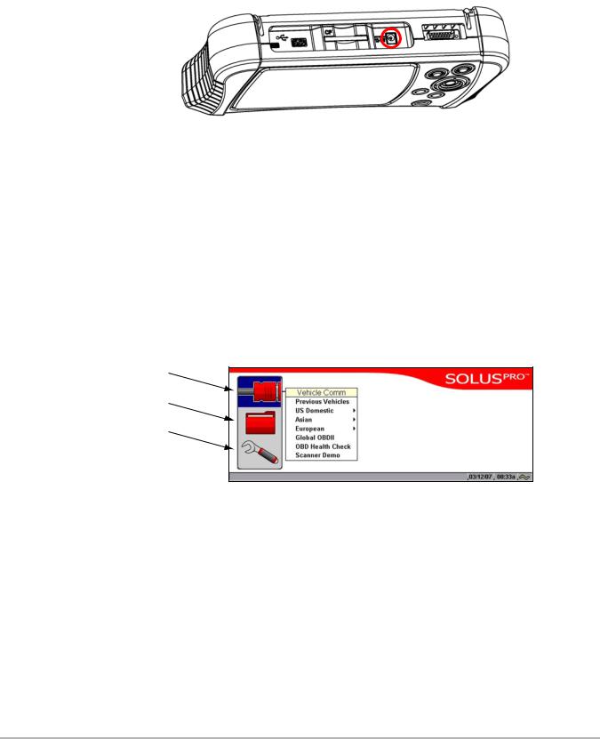
3.6Powering On the Unit
When a charged battery pack is installed, you can power on your scan tool.
For related information, see “Powering Off the Unit” on page 20.
zTo power on the scan tool:
•Press the Power button (Figure 2-2 on page 5).
The unit beeps and the main menu screen (Figure 3-8) displays after a few seconds.
1
2
3
1— Scanner—use to access vehicle tests
2— Saved Data—use to access files stored in memory
3— Utilities—use to access tool setup and operation functions Figure 3-8 Sample main menu
3.7 Setting Up to Print
This scan tool prints when connected to a compatible printers with a USB cable. Before you can use the Print button in the upper toolbar, you must do the following:
1.Set up the printer.
2.Connect a USB cable between the scan tool and the printer.
3.Configure the scan tool to print.
19
Getting Started |
Connecting to a Computer |
zTo set up the printer:
•Refer to your printer’s documentation for powering and paper loading instructions.
zTo configure the scan tool to print:
•Select a printer manufacturer and port from the Utilities > Tool Setup > Printer dialog box. See “Printer” on page 57 for details.
3.8Connecting to a Computer
Connecting your scan tool to a computer for file sharing requires the use of the optional ShopStream Connect™ software. ShopStream Connect is a free software program that can be downloaded from the Internet at software.snapon.com.
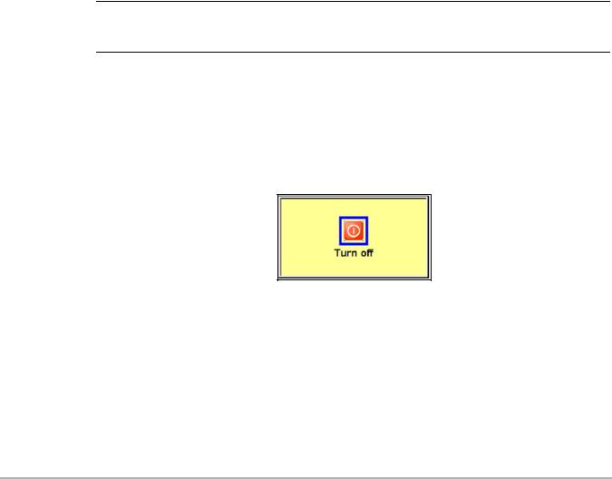
3.9 Powering Off the Unit
Use the Power button (Figure 2-2 on page 5) to turn the scan tool off.
IMPORTANT:
Do not attempt to turn off the scan tool with the power button while it is operating in Scanner mode. Exit Scanner mode before powering down.
zTo power off the unit:
1.Make sure you have exited the vehicle communication software as described in “Terminating Vehicle Communication” on page 34.
2.Exit Scanner mode as described in “Exiting Scanner Mode” on page 34.
3.Press the Power button.
The Turn off dialog box displays (Figure 3-9).
Figure 3-9 Turn off dialog box
4.Press Y/a to turn the power off, or press N/X to cancel.
3.10Adjusting Brightness and Contrast
The Brightness/Contrast button lets you to adjust the screen for optimum viewing.
20
Loading...