


DTT |
||
DIGITAL TORQUE TESTER |
||
DATA: 25 |
|
TGT TORQUE: 250 |
|
FIRST PEAK |
|
0.0OFT-LB |
||
MAIN MENU |
SETUP |
STORE |
|
2503-F-DTT |
|
25 - 250 FT.LB. |
||

Table of Contents
Important Safety Instructions .................................................................................. |
1 |
DTT System Components ............................................................................................. |
4 |
Introduction ................................................................................................................... |
5 |
Functional Description .................................................................................................. |
6 |
Specifications ............................................................................................................... |
8 |
Transducer Range and Display Resolutions .......................................................... |
9 |
Setup .................................................................................................................... |
10 |
Mounting ....................................................................................................... |
10 |
Tester Set-up ................................................................................................ |
11 |
Tests .................................................................................................................... |
12 |
Quick Check Mode ........................................................................................ |
13 |
Audit Mode .................................................................................................... |
16 |
Data Offload .................................................................................................. |
21 |

DTT Digital Torque Tester
IMPORTANT SAFETY INSTRUCTIONS
This manual contains important safety and operating instructions for the Digital Torque Tester (DTT).
Read All Instructions
Read, understand and follow all safety messages and instructions in this manual and on the test equipment. Safety messages in this section of the manual contain a signal word, a three-part message, and, in some instances, an icon. An icon, when present, gives a graphical description of the potential hazard.
General Cautions
CDI Torque Products cannot anticipate or provide
safety warnings and cautions to cover every situation that may be encountered when operating, servicing or repairing this tester. It is the responsibility of operators and servicing technicians to be knowledgeable about the procedures, tools and materials used, and to satisfy themselves that the procedures, tools and materials will not compromise their safety.
Do not attempt to operate this Digital Torque Tester until you have thoroughly read and completely understand all instructions and safety information in this manual. Failure to comply can result in accidents involving fire, electric shock or serious personal injury. Save this manual and review it frequently for continued safe operation, and use it to instruct others who may use this tester.
CDI Torque Products is not responsible for customer modification of test equipment for applications on which CDI Torque Products was not consulted.
1

DTT Digital Torque Tester
General Safety
 WARNING
Improper use can cause breakage.
•Read instructions before operating.
•Follow manufacturer’s instructions, safety precautions, and specifications when operating tools.
Broken equipment can cause injury.
Flying particles can be discharged when applying torque.
Users and bystanders must wear safety goggles.
Flying particles can cause injury.
Risk of entanglement.
•Keep body parts away from rotating parts.
•Wear a protective hair covering to contain long hair and prevent contact with moving parts.
•Do not overreach. Keep proper footing and balance at all times.
Entanglement can cause injury.
Torque Tester Safety
WARNING
• Be sure ratings for all components, including, adaptors, extensions, drivers and sockets, match or exceed the torque being applied.
• Do not use this instrument with power switch OFF. Always turn power switch ON so torque values are displayed.
• Do not turn the power switch ON with a torque instrument engaged to tester transducer.
• Be sure the capacity of the DTT matches or exceeds each application before performing a procedure.
• Pull on a wrench handle—do not push—when tester is mounted horizontally. Adjust stance to prevent a possible fall.
• Do not use extensions, such as a pipe, on a wrench handle.
• Fully engage the direction lever in the correct position when using ratchets.
2

DTT Digital Torque Tester
•Never attempt to test an impact tool or pulse type tool on this instrument.
•Mount the DTT securely to a heavy bench, wall or other support structure before applying torque.
•Do not use the DTT if it makes unusual noises, has loose parts, or shows any other sign of damage. Have repairs performed at an Authorized Service Center before use.
•Do not use chipped, cracked, or damaged sockets and accessories.
•Do not remove any labels. Replace any damaged label.
AC Adapter Safety
 WARNING
Risk of electric shock and fire.
•Do not allow conductive objects to come in contact with terminals. 120 or 220 volts present at adapter terminals.
•For indoor use only. Do not expose adapter to rain or snow. Do not use in damp locations.
•Replace defective cord immediately. Return to qualified service center for replacement.
•Do not use any other type of adapter. Using an adapter not specifically designed for this unit may damage tester.
•Do not use an extension cord with adapter.
•Do not use a damaged adapter.
•Do not disassemble adapter.
•Do not attempt to connect two adapters together.
•Do not operate adapter with damaged cord or plug. Replace immediately.
•Do not operate adapter after it is dropped, receives a sharp blow or damaged. Take the adapter to an Authorized Service Center.
•Unplug adapter from outlet before maintenance or cleaning. Turning off tester is not adequate to avoid hazard.
•Read all instructions and safety messages on battery and adapter before use.
Electric shock or fire can cause injury.
SAVE THESE INSTRUCTIONS
3

DTT Digital Torque Tester
DTT System Components
C |
B |
A |
D |
Figure 1: Digital Torque Tester System Components
A — DTT
B — AC Adapter
AC/DC transformer, Voltage Output: 9VDC, Current 1.66A
C — Battery Pack
Battery holder with 6 AA Battery cells
D — USB Cable
4

DTT Digital Torque Tester
Introduction
Use the portable DTT to test “click” type torque wrenches (adjustable and preset), torque screwdrivers, dial indicating and electronic wrenches.
The tester features a swivel-neck LCD display with selectable English or Metric units of measure. 11 models are available, ranging from 10-100 IN OZ to 60-600 FT LB.
The DTT displays torque values using a built-in straingaged transducer with an accuracy of ±0.5% of indicated test value from 10% to 100% of rated capacity, in clockwise (CW) and counter-clockwise (CCW) directions.
Torque Values
Capture and display torque values in one of four selectable modes:
•CLICK ADJUST (First Peak)
—Responds to the drop-off in torque caused by the “click” of an adjustable wrench. FIRST PEAK torque is measured, captured and displayed (CW or CCW) just prior to the drop-off, even if click torque is subsequently exceeded.
•CLICK PRESET (First Peak)
—Responds to the drop-off in torque caused by the “click” of a preset wrench. FIRST PEAK torque is measured, captured and displayed (CW or CCW) just prior to the drop-off, even if click torque is subsequently exceeded.
•DIAL / ELECT (Peak Hold)
—Captures and displays the highest torque applied (CW or CCW) until reset. Use to check dial indicating and electronic torque wrenches.
•SCREWDRIVER (Peak Hold)
—Captures and displays the highest torque applied (CW or CCW) until reset. Use to check torque limiting screwdrivers.
5
DTT Digital Torque Tester
This manual contains general information. Operating features and specifications may change without notice. CDI Torque makes no claims regarding the suitability of the information in this manual for diverse user applications.
Power Source
The power source for the DTT is the supplied AC Adapter. The tester can also be operated with the use of the 6 AA Battery Pack that accompanies the tester.
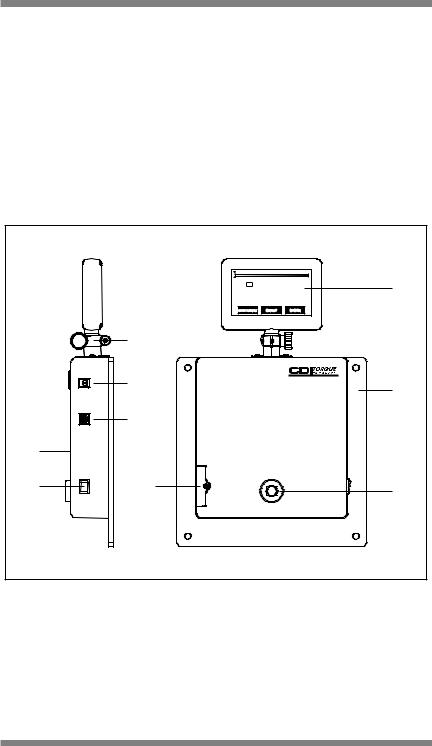
Functional Description
|
DATA: 25 |
TGT TORQUE: 250 |
A |
|
FIRST PEAK |
||
|
|
FT-LB |
|
|
|
|
|
|
MAIN MENU0.0OSETUP STORE |
|
|
|
G |
|
|
|
H |
|
B |
|
|
|
|
|
I |
|
|
F |
|
|
|
|
|
2503-F-DTT |
|
|
25 - 250 FT.LB. |
|
|
E |
D |
|
C |
|
|
|
|
Figure 2: Digital Torque Tester (DTT), Front and Side Views
A — Display
A four digit TFT display for torque readings.
B — Mounting Plate
Plate for securing tester to mounting surface. Use four 1/4” diameter bolts.
6
 Loading...