


 Loading...
5.
User Manual
ZEESCGB320A Rev. B

Legal Information
Trademarks
Snap-on, ShopStream Connect, and SOLUS are trademarks registered in the United States and other countries, of Snap-on Incorporated. All other marks are trademarks or registered trademarks of their respective holders.
Copyright Information
© 2016 Snap-on Incorporated. All rights reserved.
Disclaimer of Warranties and Limitation of Liabilities
All pictures and illustrations shown are for reference purposes only. All information, specifications and illustrations in this manual are based on the latest information available at the time of printing and are subject to change without notice. While the authors have taken due care in the preparation of this manual, nothing contained herein:
•Modifies or alters in any way the standard terms and conditions of the purchase, lease, or rental agreement under the terms of which the equipment to which this manual relates was acquired.
•Increases in any way the liability to the customer or to third parties.
Snap-on® reserves the right to make changes at any time without notice.
IMPORTANT:
Before operating or maintaining this unit, please read this manual carefully paying extra attention to the safety warnings and precautions.
Contact Information (United Kingdom)
Visit our websites at:
https://www1.snapon.com/diagnostics/UK/Diagnostics.htm
ShopStream Connect https://www1.snapon.com/ukssc
For Technical Assistance
Phone / E-mail:
+44 (0) 845 601 4736 / diagnosticsUKproductsupport@snapon.com For technical assistance in all other markets, contact your selling agent.
ZEESCGB320A Rev. B 15-L-15 GB
i

 Safety Information
READ ALL INSTRUCTIONS
For your own safety, the safety of others, and to prevent damage to the product and vehicles upon which it is used, it is important that all instructions and safety messages in this manual and the accompanying Important Safety Instructions manual be read and understood by all persons operating, or coming into contact with the product, before operating. We suggest you store a copy of each manual near the product in sight of the operator.
For your safety, read all instructions. Use your diagnostic tools only as described in the tool user’s manual. Use only manufacturer recommended parts and accessories with your diagnostic tools.
This product is intended for use by properly trained and skilled professional automotive technicians. The safety messages presented throughout this manual and the accompanying Important Safety Instructions manual are reminders to the operator to exercise extreme care when using this product.
There are many variations in procedures, techniques, tools, and parts for servicing vehicles, as well as in the skill of the individual doing the work. Because of the vast number of test applications and variations in the products that can be tested with this instrument, we cannot possibly anticipate or provide advice or safety messages to cover every situation. It is the responsibility of the automotive technician to be knowledgeable of the system being tested. It is essential to use proper service methods and test procedures. It is important to perform tests in an appropriate and acceptable manner that does not endanger your safety, the safety of others in the work area, the equipment being used, or the vehicle being tested.
It is assumed that the operator has a thorough understanding of vehicle systems before using this product. Understanding of these system principles and operating theories is necessary for competent, safe and accurate use of this instrument.
Before using the equipment, always refer to and follow the safety messages and applicable test procedures provided by the manufacturer of the vehicle or equipment being tested. Use the product only as described in it’s user manual. Use only manufacturer recommended parts and accessories with your product.
Read, understand and follow all safety messages and instructions in this manual, the accompanying Important Safety Instructions manual, and on the test equipment.
Environmental Conditions:
•This product is intended for indoor use only
•This product is rated for Pollution Degree 2 (normal conditions)
ii

Safety Information |
Safety Signal Words |
|
|
Safety Signal Words
All safety messages contain a safety signal word that indicates the level of the hazard. An icon, when present, gives a graphical description of the hazard. Safety Signal words are.
 %"/(&3
Indicates an imminently hazardous situation which, if not avoided, will result in death or serious injury to the operator or to bystanders.
 8"3/*/(
Indicates a potentially hazardous situation which, if not avoided, could result in death or serious injury to the operator or to bystanders.
 $"65*0/
Indicates a potentially hazardous situation which, if not avoided, may result in moderate or minor injury to the operator or to bystanders.
Safety Message Conventions
Safety messages are provided to help prevent personal injury and equipment damage. Safety messages communicate the hazard, hazard avoidance and possible consequences using three different type styles:
•Normal type states the hazard.
•Bold type states how to avoid the hazard.
•Italic type states the possible consequences of not avoiding the hazard.
An icon, when present, gives a graphical description of the potential hazard.
Safety Message Example
 8"3/*/(
Risk of unexpected vehicle movement.
• Block drive wheels before performing a test with engine running.
A moving vehicle can cause injury.
Important Safety Instructions
For a complete list of safety messages, refer to the accompanying Important Safety Instructions manual.
SAVE THESE INSTRUCTIONS
iii

Contents
Safety Information ................................................................................................................ |
ii |
Chapter 1: Using This Manual ............................................................................................. |
3 |
Content ................................................................................................................................... |
3 |
Conventions............................................................................................................................ |
3 |
Terminology ..................................................................................................................... |
3 |
Symbols ........................................................................................................................... |
3 |
Bold Text.......................................................................................................................... |
4 |
Notes and Important Messages ....................................................................................... |
4 |
Hyperlinks ........................................................................................................................ |
4 |
Procedures....................................................................................................................... |
4 |
Chapter 2: Introduction........................................................................................................ |
5 |
Control Buttons....................................................................................................................... |
5 |
Data and Power Connections................................................................................................. |
6 |
Battery Pack and Stand.......................................................................................................... |
7 |
Power Sources ....................................................................................................................... |
8 |
Internal Battery Pack........................................................................................................ |
8 |
AC/DC Power Supply....................................................................................................... |
8 |
Vehicle Power .................................................................................................................. |
8 |
Technical Specifications ......................................................................................................... |
9 |
Chapter 3: Basic Operation and Navigation .................................................................... |
10 |
Turning On/Off and Emergency Shutdown........................................................................... |
10 |
Turning On ..................................................................................................................... |
10 |
Turning Off ..................................................................................................................... |
10 |
Emergency Shutdown.................................................................................................... |
11 |
Basic Navigation................................................................................................................... |
11 |
Home Screen Layout ..................................................................................................... |
11 |
Title Bar.......................................................................................................................... |
12 |
Home Screen Icons ....................................................................................................... |
13 |
Common Toolbar Control Icons ..................................................................................... |
14 |
Scroll Bar ....................................................................................................................... |
15 |
Screen Messages................................................................................................................. |
16 |
System Messages.......................................................................................................... |
16 |
Communication Messages............................................................................................. |
16 |
Data Cable Connection ........................................................................................................ |
17 |
Chapter 4: Scanner............................................................................................................. |
18 |
Screen Layout and Toolbar Icons......................................................................................... |
18 |
Screen Layout................................................................................................................ |
18 |
Scanner Control Icons ................................................................................................... |
19 |
Scanner Demonstration Program ......................................................................................... |
19 |
Scanner Operation ............................................................................................................... |
20 |
Vehicle Identification ...................................................................................................... |
20 |
|
|
1 |
|

Connecting the Data Cable............................................................................................ |
21 |
System and Test Selection ............................................................................................ |
22 |
Exiting Scanner .................................................................................................................... |
38 |
SureTrack ............................................................................................................................. |
38 |
SureTrack Operation...................................................................................................... |
38 |
Wi-Fi Setup and Testing ................................................................................................ |
44 |
Testing ........................................................................................................................... |
46 |
SureTrack Troubleshooting............................................................................................ |
48 |
Chapter 5: OBD-II/EOBD .................................................................................................... |
51 |
Basic Operations .................................................................................................................. |
51 |
Screen Layout and Toolbar Controls ............................................................................. |
51 |
Connecting the Data Cable............................................................................................ |
51 |
Saving and Reviewing Data Files .................................................................................. |
51 |
OBD-II/EOBD Menu ............................................................................................................. |
51 |
OBD Health Check......................................................................................................... |
52 |
OBD Direct..................................................................................................................... |
54 |
Chapter 6: Previous Vehicles and Data............................................................................ |
61 |
Previous Vehicles and Data Menu ....................................................................................... |
61 |
Vehicle History ............................................................................................................... |
61 |
View Saved Data ........................................................................................................... |
62 |
Delete Saved Data......................................................................................................... |
63 |
Chapter 7: Tools ................................................................................................................. |
64 |
Tools Menu........................................................................................................................... |
64 |
Connect-to-PC ............................................................................................................... |
65 |
Configure Shortcut Button.............................................................................................. |
65 |
System Information ........................................................................................................ |
66 |
Settings .......................................................................................................................... |
66 |
Chapter 8: Maintenance ..................................................................................................... |
74 |
Cleaning and Inspecting the Diagnostic Tool ....................................................................... |
74 |
Cleaning the Touch Screen ........................................................................................... |
74 |
Battery Pack Service ............................................................................................................ |
74 |
Battery Pack Safety Guidelines ..................................................................................... |
75 |
Replacing the Battery Pack............................................................................................ |
76 |
Disposing of the Battery Pack........................................................................................ |
77 |
Index .................................................................................................................................... |
78 |
2

Chapter 1 Using This Manual
1.1 Content
This manual contains basic operating instructions and is structured in a manner to help you become familiar with your diagnostic tool features and perform basic operations.
The illustrations in this manual are intended as reference only and may not depict actual screen results, information, functions or standard equipment. Contact your sales representative for availability of other functions and optional equipment.
1.2 Conventions
The following conventions are used.
1.2.1 Terminology
The terms “Scanner” and “Scanner function” are used to describe the Scanner Function(s) of the diagnostic tool.
Examples:
•Select Scanner from the Home screen.
•From the Scanner main menu select Continue.
•The Scanner function provides many diagnostic tests.
The term “select” describes tapping/touching an icon on the touch screen, or highlighting an icon or menu choice and then selecting the confirmation menu choice such as Continue, Accept, OK,
Yes, or other similar choice.
Abbreviated example for the following procedure: “Select Brightness”
1.Navigate to and highlight the Brightness selection.
2.Select OK, or similar, button.
1.2.2Symbols
Different types of arrows are used. The “greater than” arrow (>) indicates an abbreviated set of selection (navigation) instructions.
Abbreviated example for the following procedure: “Select Tools > Connect-to-PC”
1.Select Tools from the home screen.
2.Highlight Connect-to-PC on the Tools menu.
3.Select Connect-to-PC.
The solid arrows (e, c, d, b) are navigational instructions for the four directions of the directional buttons.
Example: Press the down d arrow.
3

Using This Manual |
Conventions |
|
|
1.2.3 Bold Text
Bold emphasis is used in procedures to highlight selectable items such as control buttons, icons and menu options.
Example: Press the OK button
1.2.4 Notes and Important Messages
The following messages are used.
Notes
A NOTE provides helpful information such as additional explanations, tips, and comments. Example:
NOTE:
i For additional information refer to...
Important
IMPORTANT indicates a situation which, if not avoided, may result in damage to the test equipment or vehicle.
Example:
IMPORTANT:
Do not disconnect the data cable while the diagnostic tool is communicating with the ECM.
1.2.5 Hyperlinks
Hyperlinks, or hot links, that take you to other related articles, procedures, and illustrations are available in electronic documents. Blue colored text indicates a selectable hyperlink.
Example:
IMPORTANT:
Read all applicable Safety Information before using this diagnostic tool!
1.2.6 Procedures
An arrow icon in the left-margin area indicates a procedure.
Example:
zTo change screen views:
1.Select the Graph icon.
The dropdown menu displays.
2.Select an option from the menu.
The screen layout changes to the format selected.
4
Chapter 2 |
Introduction |
This chapter introduces the basic features of the diagnostic tool, including the control buttons, data connections, battery pack and power sources. Technical Specifications are provided at the end of this chapter.
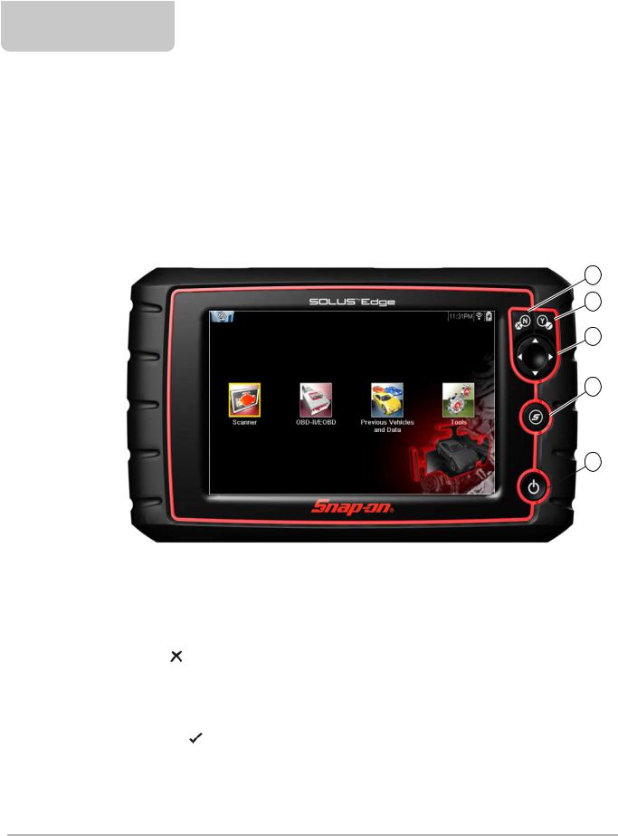
2.1 Control Buttons
There are four “push type” control buttons and one “thumb pad rocker type” multi-directional button located on the right side of the diagnostic tool. All other diagnostic tool operations are controlled through the touch screen.
|
|
|
|

Figure 2-1 Front view
Item |
|
Button |
Description |
|
|
|
|
|
|
|
• To exit a menu or program. |
1 |
|
|
|
N/X or Cancel - Push |
• To close an open list and return to the previous |
|
|
|
|
type button |
menu or screen. |
|
|
|
|
|
• To answer “No” when a yes/no choice is given. |
|
|
|
|
|
|
|
|
|
|
|
• To confirm a selection from a menu or program |
|
|
|
|
|
• To select an item that was highlighted using the |
|
|
|
|
|
|
2 |
|
|
|
Y/a or Accept - Push |
direction arrows. |
|
|
|
type button |
• To advance to the next screen in a series. |
|
|
|
|
|
||
|
|
|
|
|
• To answer “Yes” when a yes or no choice is |
|
|
|
|
|
|
|
|
|
|
|
given. |
|
|
|
|
|
|
5

Introduction |
|
|
|
|
|
|
Data and Power Connections |
|
|
|
|
|
|
|
|
|
|
|
|
|
|
|
|
|
|
|
|
Item |
|
|
Button |
Description |
|
||
|
|
|
|
|
|
|
|
Buttons move the cursor or highlight in their |
|
|
|
|
|
|
|
|
respective direction: |
|
3 |
|
|
|
|
|
Directional - Thumb |
• Up (b) |
|
|
|
|
|
|
|
pad rocker type buttons |
• Down (d) |
|
|
|
|
|
|
|
|
• Left (e) |
|
|
|
|
|
|
|
|
• Right (c) |
|
|
|
|
|
|
|
S (Shortcut) - Push type |
Programmable function button that can provide a |
|
|
|
|
|
|
|
||
|
4 |
|
|
|
|
|
shortcut for performing a variety of routine tasks. |
|
|
|
|
|
|
|
button |
Refer to Configure Shortcut Button‚ on page 65 for |
|
|
|
|
|
|
|
|
||
|
|
|
|
|
|
|
|
additional information. |
|
|
|
|
|
|
|
|
|
|
|
|
|
|
|
|
|
|
|
5 |
|
|
|
|
|
Power (On/Off) - Push |
Turns the diagnostic tool on and off. Also, press and |
|
|
|
|
|
|
|||
|
|
|
|
|
|
type button |
hold for 5 seconds for emergency shutdown |
|
|
|
|
|
|
|
|
||
|
|
|
|
|
|
|
|
|
|
|
|
|
|
|
|
|
|
2.2 Data and Power Connections
Connectors and jacks for data communication cables and the AC/DC Power Supply are located on the top of the diagnostic tool.
|
|
|
|
|
Figure 2-2 Top view
Item |
Description |
Battery Status Indicator LED
•Green - battery is fully charged
1• Red - battery is charging
•Amber - indicates a battery issue
2DC Power Supply Jack - AC/DC power supply connection
3Mini USB Jack - USB cable connection used to transfer saved data files to a personal computer Micro secure digital (uSD) Card - contains operating system programming. IMPORTANT The
4uSD card must be installed for the diagnostic tool to operate. Do not remove the uSD card while the diagnostic tool is powered on.
5Data Cable Connector - Data cable connection used to connect the diagnostic tool to a vehicle data link connector
6
Introduction |
Battery Pack and Stand |
|
|
2.3 Battery Pack and Stand
|
|
|
1— Battery Pack
2— Battery Cover
3— Built in-Stand (shown open) - The built-in stand extends from the back of the diagnostic tool and clips into the diagnostic tool for storage.
Figure 2-3 Back view
7

Introduction |
Power Sources |
|
|
2.4 Power Sources
Your diagnostic tool can receive power from any of the following sources:
•Internal Battery Pack
•AC/DC Power Supply
•Vehicle Power
2.4.1Internal Battery Pack
The diagnostic tool can be powered from the internal rechargeable battery pack. A fully charged battery provides sufficient power for about 3.5 hours of continuous operation.
The battery is recharged when an external power source is connected. Battery charging occurs when the diagnostic tool is connected to a vehicle data link connector (DLC) using the Data Cable or when the AC/DC Power Supply is connected to a live AC power source.
The Battery Status Indicator LED (located next to the DC power supply jack) indicates battery status (Figure 2-3).
•Green - indicates battery is fully charged
•Red - indicates battery is charging
•Amber - indicates a battery issue. This is usually caused by excessive battery temperature (above 104°F/40°C), which disables charging. Allow the diagnostic tool to cool down be continuing operation.
2.4.2AC/DC Power Supply
The diagnostic tool can be powered from a standard AC outlet using the AC/DC power supply. The connector on the end of the output cable of the AC/DC power supply attaches to the DC power supply input jack on top of the diagnostic tool. Use only the AC/DC power supply provided.
IMPORTANT:
Never connect the AC/DC power supply to the DC power supply input on the diagnostic tool when the diagnostic tool is communicating with a vehicle.
2.4.3 Vehicle Power
All OBD-II/EOBD vehicles have vehicle battery power (B+) available on the DLC. The diagnostic tool is powered through the Data Cable when connected to the vehicle DLC. A green LED indicator on the DLC end of the data cable, illuminates when power is being supplied to the cable. If the LED fails to illuminate, check that the data cable is properly connected and then check the DLC power circuit. See Data Cable Connection‚ on page 17 for additional data cable information.
An optional power cable is required when testing non-OBD-II/EOBD models that do not have vehicle battery power (B+) available on the DLC. Contact your sales representative for availability.
IMPORTANT:
Never connect the optional power cable to the DC power supply input on the diagnostic tool when the diagnostic tool is communicating with a vehicle.
8

Introduction Technical Specifications
2.5 Technical Specifications
Item |
Description / Specification |
|
Touch Screen |
Resistive Touch Panel |
|
|
|
|
Display |
8.0 inch diagonal, Color LCD |
|
|
||
800 x 480 resolution SWVGA |
||
|
||
|
|
|
|
Rechargeable lithium-ion battery pack |
|
Battery |
|
|
Approximately 3.5 hour run time |
||
|
|
|
|
Approximately 5 hour charge time |
|
|
|
|
DC Jack Operating |
10 to 30VDC |
|
Voltage |
||
|
||
Width |
11.1 in. (281 mm) |
|
|
|
|
Height |
6.3 in. (160 mm) |
|
|
|
|
Depth |
1.6 in. (40.3 mm) |
|
|
|
|
Weight (including |
2.6 lb (1.18 kg) |
|
battery): |
||
|
||
Operating Temperature |
At 0 to 90% relative humidity (non-condensing) |
|
Range (ambient) |
32 to 113°F (0 to 45°C) |
|
|
|
|
Storage Temperature |
At 0 to 70% relative humidity (non-condensing) |
|
(ambient) |
–4 to 140°F (–20 to 60°C) |
|
|
|
|
Environmental |
This product is intended for indoor use only |
|
Conditions |
|
|
This product is rated for Pollution Degree 2 (normal conditions) |
||
|
|
|
Power Supply |
Supply Rating; 15 VDC, 2A |
|
|
|
9

Chapter 3
Basic Operation and
Navigation
This chapter describes basic diagnostic tool operation, navigation, screen layout, icon functions, and screen messages. Before you operate the diagnostic tool, make sure the battery pack is fully charged or the diagnostic tool is powered by the AC power supply.
3.1 Turning On/Off and Emergency Shutdown
The following sections describe how to turn the diagnostic tool on and off and how to perform an emergency shutdown.
3.1.1 Turning On
The diagnostic tool will automatically turn on and open the Home screen (Figure 3-1) when power is supplied through the Data Cable or by the AC/DC Power Supply. If the diagnostic tool does not automatically turn on, press and release the Power button on the front of the diagnostic tool to turn the diagnostic tool on.
3.1.2 Turning Off
IMPORTANT:
All vehicle communication must be terminated BEFORE turning off the diagnostic tool. A warning message displays if you attempt to turn the diagnostic tool off while communicating with the vehicle. Forcing a shut down while communicating may lead to ECM problems on some vehicles. Never disconnect the Data Cable when the diagnostic tool is communicating with the vehicle ECM.
zTo turn off the diagnostic tool:
1.Press the N/X button or select the Back or Home icon to navigate to the Home screen. The “stopping communication” message appears briefly before the Home screen displays.
2.Disconnect the diagnostic tool Data Cable from the vehicle.
3.Press and release the Power button. A confirmation screen displays.
4.Press the Y/a button or select OK from the menu to turn the diagnostic tool off. To continue operating, press the N/X button or select Cancel from the menu.
10

Basic Operation and Navigation |
Basic Navigation |
|
|
3.1.3 Emergency Shutdown
IMPORTANT:
Using the emergency shutdown procedure while communicating with the vehicle ECM may lead to ECM problems on some vehicles.
During normal operation turn the diagnostic tool off using the Turning Off procedure above. The emergency shutdown procedure should only be used If the diagnostic tool does not respond to navigation or control buttons or exhibits erratic operation. To force an emergency shutdown, press and hold the Power button for five seconds until the diagnostic tool turns off.
3.2 Basic Navigation
3.2.1 Home Screen Layout
The Home screen includes a title bar and main body. The Home screen contains icons, one for each of the primary diagnostic tool functions.
1— Title Bar
2— Main Body
Figure 3-1 Home screen
11

Basic Operation and Navigation |
Basic Navigation |
|
|
3.2.2 Title Bar
The title bar at the top of the screen provides basic information about current diagnostic tool operating conditions. Title bar options vary depending upon vehicle make and model, what function is active, what test is being performed, or what menu is selected. The title bar contains information only, there are no selectable items.
Elements of the Title bar let you know at a glance:
•What diagnostic tool function is currently active.
•The current time.
•Wi-Fi signal strength
•The source and status of the power being supplied to the diagnostic tool.
An active function icon is always displayed along the left-hand edge of the Title bar. These icons resemble their Home screen icon counterparts in appearance and color. The name of the function displays to the right of the icon on some screens.
A real time clock displays to the left of the power supply icon. The clock is powered by a dedicated internal battery, so the correct time is maintained even when the main battery pack is discharged. Use the Tools function to set the clock and format how time is displayed. See Clock Settings‚ on page 71 for additional information.
The Title bar displays other information that varies depending upon what functions are being performed. Other information may include:
•The identification (ID) of the test vehicle
•The name of the active menu or function
•The name of the test being performed
Table 3-1 Title Bar Icons
|
Icon |
Function |
|
Icon |
Function |
||||||||
|
|
|
|
|
|
|
|
|
|
|
|
|
|
|
|
|
|
|
|
|
Full Battery Charge Level - Indicates |
|
|
|
|
|
Active Vehicle Communication - |
|
|
|
|
|
|
|
power is being supplied by the internal |
|
|
|
|
|
Indicates the diagnostic tool is actively |
|
|
|
|
|
|
|
battery pack. Horizontal bars diminish |
|
|
|
|
|
communicating with a vehicle. |
|
|
|
|
|
|
|
|
|
|
|
|
||
|
|
|
|
|
|
|
as the battery discharges. |
|
|
|
|
|
|
|
|
|
|
|
|
|
|
|
|
|
|
||
|
|
|
|
|
|
|
|
|
|
|
|
|
|
|
|
|
|
|
|
|
|
|
|
|
|
|
|
|
|
|
|
|
|
|
Low Battery Charge Level - Indicates |
|
|
|
|
|
Wi-Fi Signal Strength - Indicates |
|
|
|
|
|
|
|
|
|
|
|
|
signal strength of the wireless network |
|
|
|
|
|
|
|
|
the internal battery pack is low and |
|
|
|
|
|
|
|
|
|
|
|
|
|
needs to be recharged immediately. A |
|
|
|
|
|
connection. |
|
|
|
|
|
|
|
|
|
|
|
|
Three bars - indicate full strength signal |
|
|
|
|
|
|
|
|
warning message will also display on |
|
|
|
|
|
|
|
|
|
|
|
|
|
|
|
|
|
|
Zero to 1 bar - indicate weak or no |
|
|
|
|
|
|
|
|
|
|
|
|
|
||
|
|
|
|
|
|
|
the screen when the battery gets low. |
|
|
|
|
|
|
|
|
|
|
|
|
|
|
|
|
|
|
signal |
|
|
|
|
|
|
|
|
|
|
|
|
|
|
|
|
|
|
|
|
|
|
|
|
|
|
|
|
|
|
|
|
|
|
|
|
External Power Connected - |
|
|
|
|
|
|
|
|
|
|
|
|
|
Indicates power is being supplied |
|
|
|
|
|
|
|
|
|
|
|
|
|
through the data cable connection to a |
|
|
|
|
|
|
|
|
|
|
|
|
|
vehicle or by the AC/DC Power Supply. |
|
|
|
|
|
|
|
|
|
|
|
|
|
|
|
|
|
|
|
|
12

Basic Operation and Navigation |
Basic Navigation |
|
|
3.2.3 Home Screen Icons
Each available diagnostic tool function is represented by a icon on the home screen. The table below provides descriptions of the icon functions.
Select an icon from the Home screen to launch a function. You can also use the control buttons to activate a function, a yellow border around the icon indicates it is highlighted, or in focus. Use the Directional buttons (e, c, b, d) to highlight the desired function and then press the Y/a button to select it. A “please wait” message may display briefly, then automatically clear once the function is loaded and ready for use.
Table 3-2 Home screen icons
Function Name |
Function Icon |
Description |
|
|
|
Used to communicate with the electronic control systems of
Scanner a vehicle. This function allows you to retrieve diagnostic trouble codes (DTCs), view PID data and perform diagnostic
tests. See Scanner‚ on page 18 for details.
Allows you to access generic OBD-II/EOBD data and tests OBD-II/EOBD without identifying the vehicle being tested. See OBD-II/
EOBD‚ on page 51 for details.
Previous |
Allows you to quickly reconfigure the diagnostic tool to a |
|
recently tested vehicle and to access saved data files.See |
||
Vehicle & Data |
||
Previous Vehicles and Data‚ on page 61 for details. |
||
|
Allows you to adjust diagnostic tool settings to your personal Tools preferences and perform other special functions. See Tools‚
on page 64 for details.
13

Basic Operation and Navigation |
Basic Navigation |
|
|
3.2.4 Common Toolbar Control Icons
Common control icon functions are described in the following table. Specific function control icons are described in their applicable chapters. Displayed control icons vary depending on the active function or test. Select a control icon on a screen to activate a control function. You can also use the control buttons to activate a function, a yellow border around the icon indicates it is highlighted, or in focus. Use the Directional buttons (e, c, b, d) to highlight the desired function and then press the Y/a button to select it.
|
Icon |
Function |
|
Icon |
Function |
||
|
|
|
Back - Returns to the previously |
|
|
|
Record - Indicates the data being |
|
|
|
|
|
|
||
|
|
|
viewed screen. Icon is located on the |
|
|
|
displayed is paused and not being |
|
|
|
left-hand edge of the toolbar. |
|
|
|
updated. Selecting resumes data |
|
|
|
|
|
|
|
collection. |
|
|
|
|
|
|
|
|
|
|
|
|
|
|
|
|
|
|
|
Home - Returns to the Home screen. |
|
|
|
Tools - Opens the tools menu. |
|
|
|
|
|
|
||
|
|
|
Icon is located next to the Back icon |
|
|
|
|
|
|
|
on the left side of the toolbar. |
|
|
|
|
|
|
|
|
|
|
|
|
|
|
|
|
|
|
|
|
|
|
|
Save - Writes data from buffer |
|
|
|
|
|
|
|
memory to a file. The saved “movie” |
|
|
|
|
|
|
|
|
|
|
|
|
|
|
|
file can be accessed for future |
|
|
|
|
|
|
|
reference by selecting Previous |
|
|
|
|
|
|
|
Vehicles and Data > View Saved |
|
|
|
|
|
|
|
|
|
|
|
|
|
|
|
Data. |
|
|
|
|
|
|
|
|
|
|
|
|
|
|
|
|
|
|
||
The control icons below are used to navigate through |
|
||||||
paused or saved “movie” files during playback. |
|
|
|
|
|||
|
|
|
Step Forward - allows forward |
|
|
|
Step Back - allows backward |
|
|
|
movement in singular steps. To |
|
|
|
movement in singular steps. To |
|
|
|
quickly step forward, select this icon |
|
|
|
quickly step backward, select this icon |
|
|
|
(yellow frame appears) then press and |
|
|
|
(yellow frame appears) then press and |
|
|
|
hold the Y/a button. |
|
|
|
hold the Y/a button. |
|
|
|
(Note: To quickly step forward during |
|
|
|
(Note: To quickly step backward |
|
|
|
Scanner data playback, press and |
|
|
|
during Scanner data playback, press |
|
|
|
hold the icon down until a red frame |
|
|
|
and hold the icon down until a red |
|
|
|
appears around the icon.) |
|
|
|
frame appears around the icon.) |
|
|
|
|
|
|
|
|
|
|
|
Skip Forward - allows forward |
|
|
|
Skip Back - allows backward |
|
|
|
movement in multiple steps. To quickly |
|
|
|
movement in multiple steps. To quickly |
|
|
|
skip forward, select this icon (yellow |
|
|
|
skip backward, select this icon (yellow |
|
|
|
frame appears around icon) then |
|
|
|
frame appears around icon) then |
|
|
|
press and hold the Y/a button |
|
|
|
press and hold the Y/a button. |
|
|
|
|
|
|
|
|
14

Basic Operation and Navigation |
Basic Navigation |
|
|
3.2.5 Scroll Bar
A vertical scroll bar appears along the right-hand edge of the screen when additional data expands above or below what is currently on the screen (Figure 3-2).
|
|
|
|
|
Figure 3-2 Scroll bar
1— Beginning - Moves to beginning of data displayed
2— Step up - Moves up one increment of the data displayed
3— Slider (position indicator) - Select and drag the Slider to scroll through data. The slider indicates the relative position of the current screen to the total available data.
4— Step down - Moves down one increment of the data displayed 5— End - Moves to end of data displayed
The Up (b) and Down (d) directional buttons can also be used to move through the data one line at a time. Press and hold a directional button to rapidly scroll through data.
15

Basic Operation and Navigation |
Screen Messages |
|
|
3.3 Screen Messages
3.3.1 System Messages
There are four types of system messages that may be displayed:
Message Type |
Description |
|
Loading and |
Loading and connecting messages display when the diagnostic tool is performing an |
|
internal operation, such as loading a database, establishing communications with the |
||
Connecting |
vehicle, or initiating a test. The message automatically clears once the internal |
|
|
operation is complete. |
|
|
|
|
|
Confirmation messages inform you when you are about to perform an action that cannot |
|
Confirmation |
be reversed or when an action has been initiated that requires a confirmation to |
|
continue.When a response is not required, the message displays briefly, then |
||
|
||
|
disappears. |
|
|
|
|
Warning |
Warning messages inform you when completing the selected action may result in an |
|
irreversible change or in the loss of data. A confirmation is required to continue |
||
|
||
|
|
|
Error |
Error messages inform you when a system or procedural error has occurred, for |
|
example if the data cable becomes disconnected during operation. |
||
|
||
|
|
3.3.2 Communication Messages
When “no communication” messages are displayed, it indicates the diagnostic tool and the vehicle electronic control module are not communicating.
The following conditions cause “no communication” messages to display:
•The diagnostic tool is unable to establish a communication link with the vehicle.
•The vehicle is not equipped with the system that was selected.
•There is a loose connection.
•There is a blown vehicle fuse.
•There is a wiring fault on the vehicle.
•There is a circuit fault in the data cable or adapter.
•Incorrect vehicle identification was entered.
Refer to the Vehicle Communication Software manuals for manufacturer-specific problems.
16
Basic Operation and Navigation |
Data Cable Connection |
|
|
3.4 Data Cable Connection
Connection of the data cable to the diagnostic tool and vehicle DLC is required for Scanner and OBD-II/EOBD testing.
Depending on the vehicle, the supplied DA-4 data cable may be used alone or may require optional adapters.
•All OBD-II/EOBD compliant vehicles - Use the supplied DA-4 data cable. The 26-pin end of the cable attaches to the data cable connector on the top of the diagnostic tool. The16-pin end connects to the vehicle DLC. The cable connectors are secured with captive screws.
•All non-OBD-II/EOBD (OBD-I) compliant vehicles - Use the supplied DA-4 data cable with the optional DA-5 adapter and a manufacturer specific adapter. The 26-pin end of the cable attaches to the data cable connector on the top of the diagnostic tool. The16-pin end connects to the DA-5 adapter, the DA-5 adapter connects to the manufacturer specific adapter and then connects to the vehicle DLC. The cable connectors are secured with captive screws.
On-screen cable and adapter connection instructions are provided while using the Scanner and OBD-II/EOBD functions. The instructions may also include the location of the vehicle DLC (Figure 3-3). If required, additional connection information can be found in the appropriate vehicle communication software manual for the vehicle. Vehicle communication software manuals are available online, see the website information at the front of this manual
Figure 3-3 Vehicle connection data cable message
For data cable vehicle power connection information, see Vehicle Power‚ on page 8.
zTo connect the data cable to the vehicle:
1.Follow the on-screen instructions for connecting to the vehicle (Figure 3-3).
2.Select Continue once the data cable is connected.
The diagnostic tool establishes communication then displays a list of available tests. If the diagnostic tool is unable to establish a communications link, a “no communications” message displays.
3.Select from the available tests to open a submenu of test options.
17
Chapter 4 |
Scanner |
This chapter describes the basic operation of the Scanner function. The Scanner icon is located on the Home screen.
The Scanner function allows your diagnostic tool to communicate with the electronic control systems of a vehicle. This allows you to retrieve diagnostic trouble codes (DTCs), view PID data and perform diagnostic tests.
4.1 Screen Layout and Toolbar Icons
The following screen layout and toolbar controls apply to both the Scanner and the OBD-II/EOBD functions.
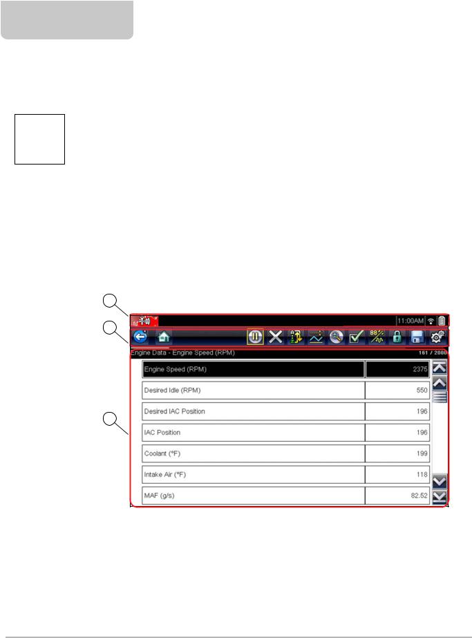
4.1.1 Screen Layout
'PSE 'PDVT - %PID 1
1— Title bar—shows active test, vehicle and diagnostic tool status 2— Toolbar—contains control icons
3— Main body—displays menus, PID and test data
Figure 4-1 Screen layout
The Title bar appears for all functions and displays information only, there are no selectable items. Refer to Title Bar‚ on page 12 for details.
18

Scanner |
Scanner Demonstration Program |
|
|
4.1.2 Scanner Control Icons
The scanner toolbar contains control icons. Control icons may vary depending on the active function or test. A yellow frame surrounding an icon (highlighted), indicates it is selected. Other control icons (not shown) are described in Common Toolbar Control Icons‚ on page 14.
|
Icon |
Function |
|
Icon |
Function |
||
|
|
|
Pause - Indicates PID data from the |
|
|
|
Custom Data List - Opens a menu for |
|
|
|
|
|
|
||
|
|
|
vehicle is being displayed. Selecting |
|
|
|
selecting which PIDs display in the list. |
|
|
|
pauses data collection. |
|
|
|
|
|
|
|
|
|
|
|
|
|
|
|
|
|
|
|
|
|
|
|
Clear - Erases all the PID data in the |
|
|
|
Change View - Changes display |
|
|
|
|
|
|
||
|
|
|
buffer and begins a new recording. |
|
|
|
options between PID list or graph |
|
|
|
Selecting opens a confirmation |
|
|
|
displays. |
|
|
|
message. |
|
|
|
|
|
|
|
|
|
|
|
|
|
|
|
|
|
|
|
|
|
|
|
Trigger - Opens a menu that allows |
|
|
|
Lock/Unlock - Locks or unlocks the |
|
|
|
you to set, arm, and clear threshold |
|
|
|
highlighted parameter. Locked PIDs |
|
|
|
values that automatically trigger PID |
|
|
|
move to the top of the list and do not |
|
|
|
data to be saved from buffer memory |
|
|
|
scroll as you move through the data. |
|
|
|
to a file. |
|
|
|
|
|
|
|
|
|
|
|
|
|
|
|
Zoom - Incrementally increases and |
|
|
|
Sort - Determines the order in which |
|
|
|
|
|
|
||
|
|
|
decreases the scale of the data being |
|
|
|
PIDs are listed on the screen. |
|
|
|
displayed. |
|
|
|
|
|
|
|
|
|
|
|
|
|
|
|
|
|
|
|
|
4.2 Scanner Demonstration Program
The Scanner demonstration program contains actual ECM PID data that allows you to navigate and become familiar with the many capabilities of the Scanner function without actually connecting to a vehicle. The following sections in this chapter provide detailed information on navigating through the Scanner function and various menus. As you navigate through the Demonstration program, refer to the applicable section for additional information.
zTo start the demonstration program:
1.From the Home screen, select the Scanner icon. The manufacturer menu displays.
2.Select the Demonstration icon.
IMPORTANT:
Do not connect a vehicle to the diagnostic tool while using the Demonstration program.
3.Follow the on-screen instructions and make the selection as needed until the confirmation screen displays.
4.Select OK on the confirmation screen to load the demonstration database. A message displays “Demo mode: Do not connect to vehicle.”
5.Select Continue.
A systems menu, which shows all of the systems available for testing, displays.
6.Select a system from the menu, then select submenus as applicable to display the desired demonstration information.
19
Scanner |
Scanner Operation |
|
|
4.3 Scanner Operation
Launching Scanner opens a menu list of vehicle manufacturers and begins the process by identifying the vehicle being tested. After the vehicle is identified, a vehicle system is selected and then a specific test or function is selected to allow you to retrieve diagnostic trouble codes (DTCs), view and save PID data, or perform diagnostic tests.
zBasic Scanner Testing Procedure
1.Launch Scanner—Select the Scanner icon on the Home screen.
2.Identify the vehicle—Identify the test vehicle by selecting from the menu options.
3.Connect the data cable to the vehicle—Follow the on-screen connection instructions to connect the diagnostic tool to the test vehicle.
4.Select the system—Select the system to be tested from the systems menu.
5.Select the test from the main menu—Select the desired test.
4.3.1Vehicle Identification
The diagnostic tool displays PID data provided by the vehicle ECM. The vehicle must be correctly identified for the diagnostic tool to communicate and display PID data correctly. The vehicle identification sequence is menu driven, follow the screen prompts to enter the information. Exact procedures may vary by the make, model, and year of the vehicle.
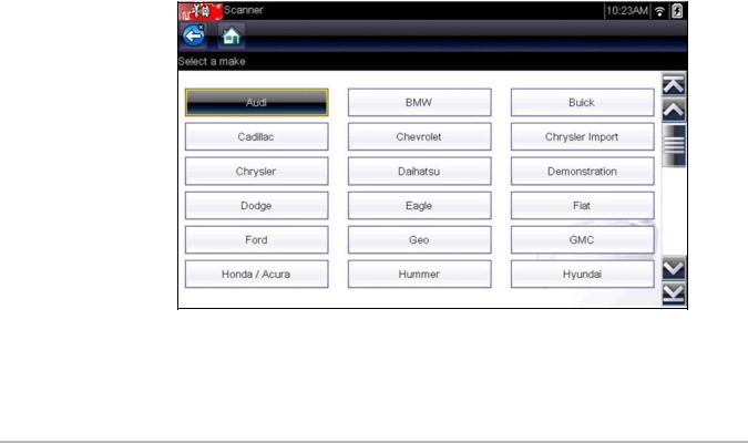
zTo identify a vehicle for testing:
1.Select the Scanner icon on the Home screen. A list of manufacturers displays (Figure 4-2).
Figure 4-2 Manufacturer list
The list includes Demonstration, which opens the Demonstration program (see Scanner Demonstration Program‚ on page 19).
20

Scanner |
Scanner Operation |
|
|
2.Select the vehicle manufacturer from the list. A model year menu displays.
3.Select the vehicle year from the menu.
A list of vehicle types or models displays. Several selections may be required to complete the vehicle identification, follow the screen prompts to enter the required information.
A confirmation screen displays once all the required information has been entered (Figure 4-3).
'PSE 'PDVT - %PID 1
$VSSFOU 7FIJDMF *EFOUJGJDBUJPO *T 7*/ " % 7FIJDMF 'PSE 'PDVT %FNP &OHJOF - %0)$ 1
Figure 4-3 Vehicle confirmation screen
4.From the Confirm Vehicle screen select:
a.OK to continue.
b.Cancel to return to the previous screen.
4.3.2Connecting the Data Cable
Connection of the data cable to the diagnostic tool and vehicle DLC is required for Scanner testing, see Data Cable Connection‚ on page 17.
21
Loading...