


 Loading...
User Manual
Scanner |
OBD-II/EOBD |
Quick Lookups |
Previous Vehicle |
Tools |
and Data |
|
|
|
ZEESC332A Rev. C
BC

Legal Information
Trademarks
Snap-on is a trademark, registered in the United States and other countries, of Snap-on Incorporated. This publication contains many Snap-on Incorporated trademarks, including but not limited to Snap-on and ETHOS. All other marks are trademarks or registered trademarks of their respective holders.
Copyright Information
© 2018 Snap-on Incorporated. All rights reserved.
Disclaimer of Warranties and Limitation of Liabilities
All pictures and illustrations shown are for reference purposes only. All information, specifications and illustrations in this manual are based on the latest information available at the time of printing and are subject to change without notice. While the authors have taken due care in the preparation of this manual, nothing contained herein:
•Modifies or alters in any way the standard terms and conditions of the purchase, lease, or rental agreement under the terms of which the equipment to which this manual relates was acquired.
•Increases in any way the liability to the customer or to third parties.
Snap-on® reserves the right to make changes at any time without notice.
IMPORTANT:
Before operating or maintaining this unit, please read this manual carefully paying extra attention to the safety warnings and precautions.
Manuals / Technical Documentation - The information in this manual is periodically revised to ensure the latest information is included. Download the latest version of this manual and other related technical documentation from the Snap-on Diagnostics website.
Software License Information
Use of Software is governed by the terms and conditions of the End User License Agreement. The End User License Agreement is provided with the diagnostic tool and the device should not be initially operated until the End User License Agreement is read. Use of the device acknowledges your acceptance of the End User License Agreement.
Patent Information
For a listing of Snap-on products that are protected by patents in the United States and elsewhere, visit: https://patents.snapon.com
ZEESC332A Rev. C 6-M-17 NA
i

Contact Information (North America)
Websites:
Snap-on Diagnostics and Information
• https://diagnostics.snapon.com
Software Subscription - Learn how to always have the latest diagnostic software on your diagnostic tool.
• https://diagnostics.snapon.com/theprogram
ShopStream Connect - Download free PC-based companion software used to transfer, save, manage, review, annotate, e-mail and print files saved or recorded on your Snap-on diagnostic tool.
• https://diagnostics.snapon.com/ssc
Training and Support - Find product support information, and watch free instructional product videos.
• https://diagnostics.snapon.com/trainingsolutions
Manuals / Technical Documentation - The information in this manual is periodically revised to ensure the latest information is included. Download the latest version of this manual and other related technical documentation at :
• https://diagnostics.snapon.com/usermanuals
Customer Care and Technical Assistance - Phone / E- mail
1-800-424-7226 / diagnostics_support@snapon.com
For technical assistance in all other markets, contact your selling agent
ii

 Safety Information
READ ALL INSTRUCTIONS
For your own safety, the safety of others, and to prevent damage to the product and vehicles upon which it is used, it is important that all instructions and safety messages in this manual and the accompanying Important Safety Instructions manual be read and understood by all persons operating, or coming into contact with the product, before operating. We suggest you store a copy of each manual near the product in sight of the operator.
For your safety, read all instructions. Use your diagnostic tools only as described in the tool user’s manual. Use only manufacturer recommended parts and accessories with your diagnostic tools.
This product is intended for use by properly trained and skilled professional automotive technicians. The safety messages presented throughout this manual and the accompanying Important Safety Instructions manual are reminders to the operator to exercise extreme care when using this product.
There are many variations in procedures, techniques, tools, and parts for servicing vehicles, as well as in the skill of the individual doing the work. Because of the vast number of test applications and variations in the products that can be tested with this instrument, we cannot possibly anticipate or provide advice or safety messages to cover every situation. It is the responsibility of the automotive technician to be knowledgeable of the system being tested. It is essential to use proper service methods and test procedures. It is important to perform tests in an appropriate and acceptable manner that does not endanger your safety, the safety of others in the work area, the equipment being used, or the vehicle being tested.
It is assumed that the operator has a thorough understanding of vehicle systems before using this product. Understanding of these system principles and operating theories is necessary for competent, safe and accurate use of this instrument.
Before using the equipment, always refer to and follow the safety messages and applicable test procedures provided by the manufacturer of the vehicle or equipment being tested. Use the product only as described in it’s user manual. Use only manufacturer recommended parts and accessories with your product.
Read, understand and follow all safety messages and instructions in this manual, the accompanying Important Safety Instructions manual, and on the test equipment.
Environmental Conditions:
•This product is intended for indoor use only
•This product is rated for Pollution Degree 2 (normal conditions)
iii

Safety Information |
Safety Signal Words |
|
|
Safety Signal Words
All safety messages contain a safety signal word that indicates the level of the hazard. An icon, when present, gives a graphical description of the hazard. Safety Signal words are.
 '$1*(5
Indicates an imminently hazardous situation which, if not avoided, will result in death or serious injury to the operator or to bystanders.
 :$51,1*
Indicates a potentially hazardous situation which, if not avoided, could result in death or serious injury to the operator or to bystanders.
 &$87,21
Indicates a potentially hazardous situation which, if not avoided, may result in moderate or minor injury to the operator or to bystanders.
Safety Message Conventions
Safety messages are provided to help prevent personal injury and equipment damage. Safety messages communicate the hazard, hazard avoidance and possible consequences using three different type styles:
•Normal type states the hazard.
•Bold type states how to avoid the hazard.
•Italic type states the possible consequences of not avoiding the hazard.
An icon, when present, gives a graphical description of the potential hazard.
Safety Message Example
 :$51,1*
Risk of unexpected vehicle movement.
• Block drive wheels before performing a test with engine running.
A moving vehicle can cause injury.
Important Safety Instructions
For a complete list of safety messages, refer to the accompanying Important Safety Instructions manual.
SAVE THESE INSTRUCTIONS
iv

 Contents
Safety Information............................................................................................................... |
iii |
Chapter 1: Using This Manual............................................................................................. |
4 |
Content................................................................................................................................... |
4 |
Conventions............................................................................................................................ |
4 |
Terminology ..................................................................................................................... |
4 |
Symbols ........................................................................................................................... |
4 |
Bold Text.......................................................................................................................... |
5 |
Notes and Important Messages....................................................................................... |
5 |
Hyperlinks ........................................................................................................................ |
5 |
Procedures....................................................................................................................... |
5 |
Chapter 2: Introduction........................................................................................................ |
6 |
Control Buttons....................................................................................................................... |
7 |
Data and Power Connections................................................................................................. |
8 |
Battery Pack Cover and Stand ............................................................................................... |
8 |
Power Sources ....................................................................................................................... |
9 |
Vehicle Power.................................................................................................................. |
9 |
Internal Battery Pack........................................................................................................ |
9 |
AC Power Supply............................................................................................................. |
9 |
Technical Specifications....................................................................................................... |
10 |
Chapter 3: Basic Operation and Navigation .................................................................... |
11 |
Turning On/Off and Emergency Shutdown........................................................................... |
11 |
Turning On..................................................................................................................... |
11 |
Turning Off..................................................................................................................... |
11 |
Emergency Shutdown.................................................................................................... |
12 |
Basic Navigation................................................................................................................... |
12 |
Home Screen Layout ..................................................................................................... |
12 |
Title Bar.......................................................................................................................... |
13 |
Home Screen Icons ....................................................................................................... |
14 |
Common Toolbar Control Icons..................................................................................... |
15 |
Scroll Bar ....................................................................................................................... |
15 |
Screen Messages................................................................................................................. |
16 |
System Messages.......................................................................................................... |
16 |
Communication Messages............................................................................................. |
16 |
Data Cable Connection ........................................................................................................ |
17 |
Chapter 4: Quick Training Guide ...................................................................................... |
18 |
Scanner Demonstration........................................................................................................ |
18 |
OBD-II/EOBD Demonstration............................................................................................... |
22 |
Chapter 5: Scanner............................................................................................................. |
25 |
Scanner Demonstration Program......................................................................................... |
25 |
Screen Layout and Toolbar Icons......................................................................................... |
26 |
1

Screen Layout................................................................................................................ |
26 |
Scanner Control Icons ................................................................................................... |
27 |
Scanner Operation ............................................................................................................... |
28 |
Vehicle Identification...................................................................................................... |
28 |
Code Scan ..................................................................................................................... |
30 |
System Main Menu Options........................................................................................... |
32 |
Codes Menu................................................................................................................... |
33 |
Saving Scanner / OBD-II/EOBD Data Files ................................................................... |
41 |
Functional Tests............................................................................................................. |
42 |
Generic Functions.......................................................................................................... |
43 |
Exiting Scanner .................................................................................................................... |
43 |
Chapter 6: OBD-II/EOBD .................................................................................................... |
44 |
Basic Operations .................................................................................................................. |
44 |
Screen Layout and Toolbar Controls ............................................................................. |
44 |
Connecting the Data Cable............................................................................................ |
44 |
Saving and Reviewing Data Files .................................................................................. |
44 |
OBD-II/EOBD Menu ............................................................................................................. |
45 |
OBD Health Check......................................................................................................... |
45 |
OBD Direct..................................................................................................................... |
48 |
Chapter 7: Quick Lookups................................................................................................. |
55 |
Oil Specs and Resets........................................................................................................... |
55 |
Operation ....................................................................................................................... |
56 |
Reset Procedure............................................................................................................ |
60 |
Tire and Wheel Service ........................................................................................................ |
63 |
Operation ....................................................................................................................... |
63 |
Chapter 8: Previous Vehicles and Data............................................................................ |
70 |
Previous Vehicles and Data Menu ....................................................................................... |
70 |
Vehicle History............................................................................................................... |
70 |
View Saved Data ........................................................................................................... |
71 |
Delete Saved Data......................................................................................................... |
72 |
Chapter 9: Tools ................................................................................................................. |
73 |
Tools Menu........................................................................................................................... |
73 |
Connect-to-PC ............................................................................................................... |
74 |
Configure Shortcut Button.............................................................................................. |
75 |
System Information........................................................................................................ |
75 |
Settings.......................................................................................................................... |
76 |
Chapter 10: ShopStream Connect .................................................................................... |
91 |
Scanner DataViewer............................................................................................................. |
93 |
Image Viewer........................................................................................................................ |
94 |
Scanner Codes Viewer......................................................................................................... |
95 |
Software Upgrades and Updates ......................................................................................... |
96 |
Chapter 11: Maintenance................................................................................................... |
97 |
Cleaning and Inspecting the Diagnostic Tool ....................................................................... |
97 |
Cleaning the Touch Screen ........................................................................................... |
97 |
Battery Pack Service ............................................................................................................ |
97 |
2

Battery Pack Safety Guidelines |
.....................................................................................98 |
Replacing the Battery Pack............................................................................................ |
99 |
Disposing of the Battery Pack...................................................................................... |
100 |
3

Chapter 1 Using This Manual
1.1 Content
This manual contains basic operating instructions and is structured in a manner to help you become familiar with your diagnostic tool features and perform basic operations.
The illustrations in this manual are intended as reference only and may not depict actual screen results, information, functions or standard equipment. Contact your sales representative for availability of other functions and optional equipment.
1.2 Conventions
The following conventions are used.
1.2.1 Terminology
The terms “Scanner” and “Scanner function” are used to describe the Scanner Function(s) of the diagnostic tool.
Examples:
•Select Scanner from the Home screen.
•From the Scanner main menu select Continue.
•The Scanner function provides many diagnostic tests.
The term “select” describes tapping/touching an icon on the touch screen, or highlighting an icon or menu choice and then selecting the confirmation menu choice such as Continue, Accept, OK,
Yes, or other similar choice.
Abbreviated example for the following procedure: “Select Brightness”
1.Navigate to and highlight the Brightness selection.
2.Select OK, or similar, button.
1.2.2Symbols
Different types of arrows are used. The “greater than” arrow (>) indicates an abbreviated set of selection (navigation) instructions.
Abbreviated example for the following procedure: “Select Tools > Connect-to-PC”
1.Select Tools from the home screen.
2.Highlight Connect-to-PC on the Tools menu.
3.Select Connect-to-PC.
The solid arrows (e, c, d, b) are navigational instructions for the four directions of the directional buttons.
Example: Press the down d arrow.
4

Using This Manual |
Conventions |
|
|
1.2.3 Bold Text
Bold emphasis is used in procedures to highlight selectable items such as control buttons, icons and menu options.
Example: Press the OK button.
1.2.4 Notes and Important Messages
The following messages are used.
Notes
A NOTE provides helpful information such as additional explanations, tips, and comments. Example:
NOTE:
i For additional information refer to...
Important
IMPORTANT indicates a situation which, if not avoided, may result in damage to the test equipment or vehicle.
Example:
IMPORTANT:
Do not disconnect the data cable while the diagnostic tool is communicating with the ECM.
1.2.5 Hyperlinks
Hyperlinks, or hot links, that take you to other related articles, procedures, and illustrations are available in electronic documents. Blue colored text indicates a selectable hyperlink.
Example:
IMPORTANT:
Read all applicable Safety Information before using this diagnostic tool!
1.2.6 Procedures
An arrow icon in the left-margin area indicates a procedure.
Example:
zTo change screen views:
1.Select the Graph icon.
The dropdown menu displays.
2.Select an option from the menu.
The screen layout changes to the format selected.
5
Chapter 2 |
Introduction |
This diagnostic tool allows you to communicate with various vehicle control systems (e.g. engine, transmission, antilock brake system (ABS), body, instrument cluster, etc) to:
•Perform OEM specific functional tests and relearn procedures
•Retrieve and clear diagnostic trouble codes (DTCs)
•View parameter (PID) data in text or graph format, and save it for future review
•Set and arm PID triggers to automatically capture and save PID data to buffer memory
•Access global OBD-II/EOBD service modes, freeze frame data, readiness monitors, and more
In addition you can:
•Quickly retrieve previously tested vehicles, to save setup time during repeat testing
•Save screen shots, to quickly capture specific data for future review
•Interface with ShopStream Connect™ software on your PC to transfer files from the diagnostic tool to your PC, download software updates and more.
This chapter introduces the basic features of the diagnostic tool, including the control buttons, data connections, battery pack and power sources. Technical Specifications are provided at the end of this chapter.
6

Introduction |
Control Buttons |
|
|
2.1 Control Buttons
There are four “push type” control buttons and one “thumb pad rocker type” multi-directional button located on the right side of the diagnostic tool. All other diagnostic tool operations are controlled through the touch screen.
Scanner |
OBD-II/EOBD |
Quick Lookups |
Previous Vehicle |
Tools |
and Data |
|
|
|
1 |
2 |
3 |
4 |
5
Figure 2-1 Front view
Item |
Button |
Description |
|
|
|
|
• To confirm a selection from a menu or program. |
|
|
|
• To select an item that was highlighted using the |
1 |
|
Y/a or Accept - Push |
direction arrows. |
|
type button |
• To advance to the next screen in a series. |
|
|
|
||
|
|
|
• To answer “Yes” when a yes or no choice is |
|
|
|
given. |
|
|
|
• To exit a menu or program. |
2 |
|
N/X or Cancel - Push |
• To close an open list and return to the previous |
|
|
type button |
menu or screen. |
|
|
|
• To answer “No” when a yes/no choice is given. |
|
|
|
Buttons move the cursor or highlight in their |
|
|
|
respective direction: |
3 |
|
Directional - Thumb |
• Up (b) |
|
|
pad rocker type buttons |
• Down (d) |
|
|
|
• Left (e) |
|
|
|
• Right (c) |
|
|
(Shortcut) - Push type |
Programmable function button that can provide a |
4 |
|
shortcut for performing a variety of routine tasks. |
|
|
button |
Refer to Configure Shortcut Button‚ on page 75 for |
|
|
|
||
|
|
|
additional information. |
|
|
|
|
5 |
|
Power (On/Off) - Push |
Turns the diagnostic tool on and off. Also, press and |
|
type button |
hold for 5 seconds for emergency shutdown. |
|
|
|
||
|
|
|
|
7
Introduction |
Data and Power Connections |
|
|
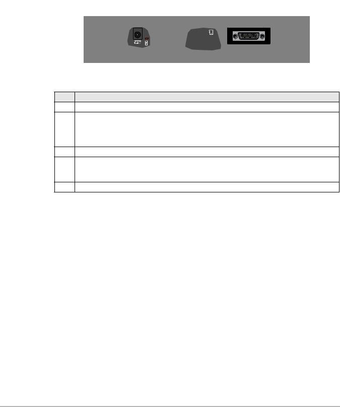
2.2 Data and Power Connections
All diagnostic tool connections are located on the top of the diagnostic tool.
1 |
2 |
3 |
4 |
5 |
Figure 2-2 Top view
Item |
Description |
1Power Supply Jack - connection for AC power supply
Battery Status Indicator LED
•Green - battery is fully charged 2 • Red - battery is charging
•Amber - indicates there is a battery issue (correct before operating)
3Mini-b USB Jack - connection for USB cable to a personal computer.
Micro secure digital (µSD) Card - contains operating system programming. IMPORTANT The
4µSD card must be installed for the diagnostic tool to operate. Do not remove the µSD card while the diagnostic tool is powered on.
5Data Cable Connector - connection for vehicle data cable to vehicle data link connector (DLC).
2.3Battery Pack Cover and Stand
2 |
1 |
3 |
1— Built-in Stand - The built-in stand extends from the back of the diagnostic tool and clips into the diagnostic tool for storage.
2— Battery Pack Cover
3— Battery Pack Cover Screw
Figure 2-3 Back view
8

Introduction |
Power Sources |
|
|
2.4 Power Sources
Your diagnostic tool can be powered from any of the following sources:
2.4.1 Vehicle Power
All OBD-II/EOBD vehicles have vehicle battery power (B+) available on the DLC. The diagnostic tool is powered through the Data Cable when connected to the vehicle DLC. A green LED indicator on the DLC end of the data cable, illuminates when power is being supplied to the cable. If the LED fails to illuminate, check that the data cable is properly connected and then check the DLC power circuit. See Data Cable Connection‚ on page 17 for additional data cable information.
2.4.2 Internal Battery Pack
The diagnostic tool can be powered from the internal rechargeable battery pack. A fully charged battery provides sufficient power for about 3 hours of continuous operation.
Battery charging occurs when the diagnostic tool is connected to the AC Power Supply and to a live AC power source, or when the data cable is connected to an OBD-II/EOBD vehicle.
The Battery Status Indicator LED (located next to the power supply jack) indicates battery status (Figure 2-3).
•Green - indicates battery is fully charged
•Red - indicates battery is charging
•Amber - indicates a battery issue. This may be caused by excessive battery temperature (above 104°F/40°C), which disables charging. Allow the diagnostic tool to cool down before continuing operation.
2.4.3AC Power Supply
The diagnostic tool can be powered from a standard AC outlet using the AC power supply. The connector on the end of the output cable of the AC power supply attaches to the power supply input jack on top of the diagnostic tool. Use only the AC power supply provided.
IMPORTANT:
Never connect the AC power supply to the power supply input on the diagnostic tool when the diagnostic tool is communicating with a vehicle.
9

Introduction Technical Specifications
2.5 Technical Specifications
Item |
Description / Specification |
Touch Screen |
Resistive Touch Panel |
|
5.6 inch diagonal, LCD TFT |
Display |
|
640 x 480 resolution |
|
|
|
|
24 bit color |
|
|
|
Rechargeable lithium-ion battery pack |
Battery Pack |
|
Approximately 3 hour run time |
|
|
|
|
Approximately 5 hour charge time |
|
|
Operating System |
SMX |
|
|
Processor |
Motorola |
|
|
Input Operating Voltage |
10 to 30VDC |
AC Power Supply Rating |
Input 110-240VAC, Output 15VDC - 2A |
|
|
Width |
8.90 in. (226 mm) |
|
|
Height |
5.67 in. (144 mm) |
Depth |
1.75 in. (44.5 mm) |
|
|
Weight(includingbattery |
2.1 lb (952 g) |
pack) |
|
Operating Temperature |
At 0 to 90% relative humidity (non-condensing) |
Range (ambient) |
32 to 113°F (0 to 45°C) |
Storage Temperature |
At 0 to 70% relative humidity (non-condensing) |
(ambient) |
–4 to 140°F (–20 to 60°C) |
|
|
Environmental |
This product is intended for indoor use only |
Conditions |
|
This product is rated for Pollution Degree 2 (normal conditions) |
|
|
|
10

Chapter 3
Basic Operation and
Navigation
This chapter describes basic operation, navigation, screen layout, and icon functions. Before you operate the diagnostic tool, make sure the battery pack is fully charged or the diagnostic tool is powered by the AC power supply.
3.1 Turning On/Off and Emergency Shutdown
The following sections describe how to turn the diagnostic tool on and off and how to perform an emergency shutdown.
3.1.1 Turning On
The diagnostic tool will automatically turn on and open the Home screen (Figure 3-1) when power is supplied through the Data Cable or by the AC Power Supply. If the diagnostic tool does not automatically turn on, press and release the Power button on the front of the diagnostic tool to turn the diagnostic tool on.
3.1.2 Turning Off
IMPORTANT:
All vehicle communication must be terminated BEFORE turning off the diagnostic tool. A warning message displays if you attempt to turn the diagnostic tool off while communicating with the vehicle. Forcing a shut down while communicating may lead to ECM problems on some vehicles. Never disconnect the Data Cable when the diagnostic tool is communicating with the vehicle ECM.
zTo turn off the diagnostic tool:
1.Press the N/X button or select the Back or Home icon to navigate to the Home screen.
If vehicle communication is active, the “stopping communication” message appears briefly before the Home screen displays.
2.Disconnect the diagnostic tool Data Cable from the vehicle.
3.Press and release the Power button. A confirmation screen displays.
4.Press the Y/a button or select OK from the menu to turn the diagnostic tool off. To continue operating, press the N/X button or select Cancel from the menu.
11
Basic Operation and Navigation |
Basic Navigation |
|
|
3.1.3 Emergency Shutdown
IMPORTANT:
Using the emergency shutdown procedure while communicating with a vehicle may lead to control module problems on some vehicles.
During normal operation turn the diagnostic tool off using the Turning Off procedure described previously. The emergency shutdown procedure should only be used If the diagnostic tool does not respond, or exhibits erratic or abnormal operation. To force an emergency shutdown, press and hold the Power button for five seconds until the diagnostic tool turns off.
3.2 Basic Navigation
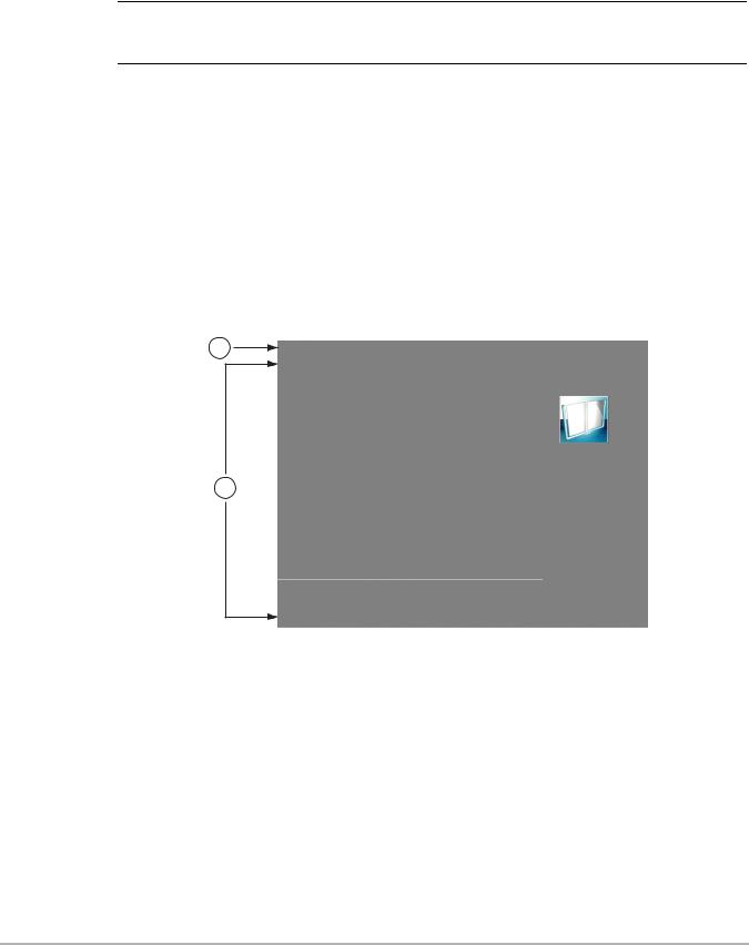
3.2.1 Home Screen Layout
The Home screen includes the title bar and function icons.
1
Scanner |
OBD-II/EOBD |
Quick Lookups |
2
Previous Vehicle |
Tools |
and Data |
|
1— Title Bar
2— Function Icons
Figure 3-1 Home screen
12

Basic Operation and Navigation |
Basic Navigation |
|
|
3.2.2 Title Bar
The title bar at the top of the screen (Figure 3-1) provides basic information about current diagnostic tool operating conditions. Title bar options vary depending upon vehicle make and model, what function is active, what test is being performed, or what menu is selected. The title bar contains information only, there are no selectable items.
Figure 3-2 Typical Title Bar (showing vehicle information)
Information the title bar may display (varies upon active function):
•Active diagnostic function.
•Active communication indicator icon.
•Current time.
•Wi-Fi signal strength
•Source and status of the power being supplied to the diagnostic tool.
•The identification (ID) of the test vehicle
•The name of the test being performed
An active function icon is always displayed in the title bar. These icons resemble their Home screen icon counterparts in appearance and color. The name of the function displays to the right of the icon on some screens.
A clock is displayed in the title bar, and is powered by a dedicated internal battery, so the correct time is maintained even when the battery pack is discharged. See Clock Settings‚ on page 81, for clock setting instructions.
Table 3-1 Title Bar Icons
|
Icon |
Function |
|
Icon |
Function |
||||||
|
|
|
|
|
|
|
|
|
|
|
|
|
|
|
|
|
Full Battery Charge Level - Indicates |
|
|
|
|
|
Active Vehicle Communication - |
|
|
|
|
|
power is being supplied by the internal |
|
|
|
|
|
|
|
|
|
|
|
|
|
|
|
|
Indicates the diagnostic tool is actively |
|
|
|
|
|
|
battery pack. Horizontal bars diminish |
|
|
|
|
|
communicating with a vehicle. |
|
|
|
|
|
|
|
|
|
|
||
|
|
|
|
|
as the battery discharges. |
|
|
|
|
|
|
|
|
|
|
|
|
|
|
|
|
||
|
|
|
|
|
|
|
|
|
|
|
|
|
|
|
|
|
|
|
|
|
|
|
|
|
|
|
|
|
Low Battery Charge Level - Indicates |
|
|
|
|
|
Wi-Fi Signal Strength - Indicates |
|
|
|
|
|
|
|
|
|
|
signal strength of the wireless network |
|
|
|
|
|
|
the internal battery pack is low and |
|
|
|
|
|
|
|
|
|
|
|
|
|
|
|
|
connection. |
|
|
|
|
|
|
needs to be recharged immediately. A |
|
|
|
|
|
|
|
|
|
|
|
|
|
|
|
|
Three bars - indicate full strength signal |
|
|
|
|
|
|
warning message will also display on |
|
|
|
|
|
|
|
|
|
|
|
|
|
|
|
|
Zero to 1 bar - indicate weak or no |
|
|
|
|
|
|
|
|
|
|
|
||
|
|
|
|
|
the screen when the battery gets low. |
|
|
|
|
|
|
|
|
|
|
|
|
|
|
|
|
signal |
|
|
|
|
|
|
|
|
|
|
|
|
|
|
|
|
|
|
|
|
|
|
|
|
|
|
|
|
|
|
External Power Connected - |
|
|
|
|
|
|
|
|
|
|
|
Indicates power is being supplied |
|
|
|
|
|
|
|
|
|
|
|
through the data cable connection to a |
|
|
|
|
|
|
|
|
|
|
|
vehicle or by the AC Power Supply. |
|
|
|
|
|
|
|
|
|
|
|
|
|
|
|
|
|
|
13

Basic Operation and Navigation |
Basic Navigation |
|
|
3.2.3 Home Screen Icons
Each available diagnostic tool function is represented by a function icon on the home screen.
Select an icon from the Home (touch) screen to start a function. You can also use the control buttons to start a function. Use the directional buttons (e, c, b, d) to highlight (a yellow border around the icon indicates it is highlighted) the desired function and then press the Y/a button to select it. A “please wait” message may display briefly, then automatically clear once the function is loaded and ready for use.
Table 3-2 Home screen icons
Function Name |
Function Icon |
Description |
|
|
|
Used to communicate with the electronic control systems of
Scanner a vehicle. This function allows you to retrieve diagnostic trouble codes (DTCs), view PID data and perform diagnostic
tests. See Scanner‚ on page 25, for details.
Allows you to access generic OBD-II/EOBD data and tests OBD-II/EOBD without identifying the vehicle being tested.
See OBD-II/EOBD‚ on page 44, for details.
Allows you quickly access OEM Oil and Tire/Wheel Quick Lookups specifications and instructions on your diagnostic tool. See
Quick Lookups‚ on page 55,.
Previous |
Allows you to quickly reconfigure the diagnostic tool to a |
|
recently tested vehicle and to access saved data files.See |
||
Vehicle & Data |
||
Previous Vehicles and Data‚ on page 70, for details. |
||
|
Allows you to adjust diagnostic tool settings to your personal Tools preferences and perform other special functions. See Tools‚
on page 73, for details.
14

Basic Operation and Navigation |
Basic Navigation |
|
|
3.2.4 Common Toolbar Control Icons
Common control icon functions are described in the following table. Specific function control icons are described in their applicable chapters. Displayed control icons vary depending on the active function or test. Select a control icon on a screen to activate a control function. You can also use the control buttons to activate a function, a yellow border around the icon indicates it is highlighted, or in focus. Use the Directional buttons (e, c, b, d) to highlight the desired function and then press the Y/a button to select it.
|
Icon |
Function |
Icon |
Function |
|
|
|
|
Save - Writes data from buffer |
|
|
Back - Returns to the previously |
|
memory to a file. The saved “movie” |
|
|
|
file can be accessed for future |
|
|
|
viewed screen. Icon is located on the |
|
|
|
|
|
reference by selecting Previous |
|
|
|
left-hand edge of the toolbar. |
|
|
|
|
|
Vehicles and Data > View Saved |
|
|
|
|
|
|
|
|
|
|
Data. |
Home - Returns to the Home screen.
Icon is located next to the Back icon Tools - Opens the tools menu. on the left side of the toolbar.
3.2.5 Scroll Bar
A vertical scroll bar appears along the right-hand edge of the screen when there is more data than can be displayed (Figure 3-3).
|
|
|
|
|
Figure 3-3 Scroll bar
1— Beginning - Moves to beginning of the data. 2— Step up - Moves up one increment of the data.
3— Slider (position indicator) - Select and drag the Slider to scroll through data. The slider indicates the relative position of the current screen to the total available data.
4— Step down - Moves down one increment of the data. 5— End - Moves to end of the data.
The Up (b) and Down (d) directional buttons can also be used to move through the data one line at a time. Press and hold a directional button to rapidly scroll through data.
15
Basic Operation and Navigation |
Screen Messages |
|
|
3.3 Screen Messages
3.3.1 System Messages
There are four types of system messages that may be displayed:
Message Type |
Description |
|
Loading and |
Loading and connecting messages display when the diagnostic tool is performing an |
|
internal operation, such as loading a database, establishing communications with the |
||
Connecting |
vehicle, or initiating a test. The message automatically clears once the internal |
|
|
operation is complete. |
|
|
|
|
|
Confirmation messages inform you when you are about to perform an action that cannot |
|
Confirmation |
be reversed or when an action has been initiated that requires a confirmation to |
|
continue.When a response is not required, the message displays briefly, then |
||
|
||
|
disappears. |
|
|
|
|
Warning |
Warning messages inform you when completing the selected action may result in an |
|
irreversible change or in the loss of data. A confirmation is required to continue. |
||
|
||
|
|
|
Error |
Error messages inform you when a system or procedural error has occurred, for |
|
example if the data cable becomes disconnected during operation. |
||
|
||
|
|
3.3.2 Communication Messages
When “no communication” messages are displayed, it indicates the diagnostic tool and the vehicle electronic control module are not communicating.
The following conditions may cause “no communication” messages to display:
•The diagnostic tool is unable to establish a communication link with the vehicle.
•The vehicle is not equipped with the system that was selected.
•There is a loose connection.
•There is a blown vehicle fuse.
•There is a wiring fault on the vehicle.
•There is a circuit fault in the data cable or adapter.
•Incorrect vehicle identification was entered.
16

Basic Operation and Navigation |
Data Cable Connection |
|
|
3.4 Data Cable Connection
Connection of the data cable to the diagnostic tool and vehicle data link connector (DLC) is required for Scanner and OBD-II/EOBD testing.
Depending on the vehicle, the supplied DA-4 data cable may be used alone or may require optional adapters.
•All OBD-II/EOBD compliant vehicles - Use the supplied DA-4 data cable. The 26-pin end of the cable attaches to the data cable connector on the top of the diagnostic tool (secure with captive screws). The16-pin end connects to the vehicle DLC.
•All non-OBD-II/EOBD (OBD-I) compliant vehicles - Use the supplied DA-4 data cable with the optional DA-5 adapter and a manufacturer specific adapter. The 26-pin end of the cable attaches to the data cable connector on the top of the diagnostic tool. The16-pin end connects to the DA-5 adapter, the DA-5 adapter connects to the manufacturer specific adapter and then connects to the vehicle DLC.
On-screen cable and adapter connection instructions may be provided while using the Scanner and OBD-II/EOBD functions. The instructions may also include the location of the vehicle DLC (Figure 3-4).
Figure 3-4 Vehicle connection data cable message
For data cable vehicle power connection information, see Vehicle Power‚ on page 9,.
17

Chapter 4 Quick Training Guide
This chapter provides step-by-step instructions that allow you to get started using the diagnostic tool and become familiar with some of the common Scanner and OBDII functions.
Two built-in demonstration modes allow you to walk-through these functions without connecting to
avehicle:
•Scanner Demonstration
•OBD-II/EOBD Demonstration
IMPORTANT:
Do not connect the diagnostic tool to a vehicle when using the demonstration modes.
4.1 Scanner Demonstration
The Scanner demonstration program allows you to navigate through many functions of the Scanner, and displays vehicle data (PIDs) and trouble codes (captured from actual vehicle) to simulate what you might see on an actual vehicle.
Links are provided (as applicable) within the demonstrations to additional topic information in this manual.
The following Scanner demonstrations are intended to be completed in sequence:
1 - Vehicle Identification
2 - Scan for Engine Codes and Save the Codes 3 - View, Configure and Save Engine Data (PIDs) 4 - Perform a Functional Test
5 - Perform a Code Scan
6 - View Saved Files (Codes, Code Scan and Data Files)
7 - Activate a Previously Identified Vehicle and View Engine Data (PIDs)
zScanner Demo 1 - Vehicle Identification
The first process in communicating with any vehicle is identifying the vehicle. The following walkthrough will guide you though this process using the Scanner demonstration mode.
1.From the Home screen, select Scanner 
2.The manufacturer (vehicle make) menu displays, select Demonstration.
IMPORTANT:
Do not connect a vehicle to the diagnostic tool while using the Demonstration program.
The simulated Vehicle ID process starts. The demonstration vehicle to be identified is a 2014 Chevrolet Tahoe, 5.3L, 4WD.
3. The year menu displays, select 2014-E
18

Quick Training Guide |
Scanner Demonstration |
|
|
4.The make menu displays, select Chevrolet
5.The model menu displays, select Tahoe (4WD) Demo - K
6.The engine menu displays, select 5.3 V8 SFI (LMG) - 0
7.The vehicle confirmation screen displays, select OK. (Selecting OK loads the specific vehicle database, in this instance it’s our demonstration database).
8.A message displays “Demo mode: Do not connect to vehicle.” Select Continue.
For more on vehicle identification, see Vehicle Identification‚ on page 28.
After the vehicle has been identified, a systems menu displays This menu shows all of the vehicle systems available (supported by the vehicle) for testing. Typical systems choices may include:
|
|
|
|
|
|
• |
Code Scan |
• |
Body Control Module |
• |
Radio |
• Clear All Codes Read |
• |
Door Module - Driver |
• |
Seat Module - Driver |
|
|
by Code Scan |
|
|
|
|
• |
Engine |
• |
Door Module - Passenger |
• |
Suspension (ESC). If Equipped. |
• |
Transmission |
• Heating and Air Conditioning |
• |
Theft Deterrent |
|
• |
Antilock Brakes |
• |
Instrument Panel Cluster |
• |
Tire Pressure Monitor |
• |
Airbag |
• |
Passenger Presence System |
• |
Transfer Case |
Most of the system menu choices are directly related to a specific vehicle system (e.g. Engine, Airbag, Tire Pressure Monitor), with the exception of Code Scan and Clear All Codes Read by Code Scan. Code Scan is a time-saving feature that allows you to scan all the vehicle systems at once for diagnostic trouble codes (DTCs). For more on Code Scan, see Code Scan‚ on page 30.
Choosing a vehicle system opens the main menu for that system which provides options for you to analyze and interact with that system. You can choose to scan for DTCs, clear DTCs, view parameter data (PIDs), perform functional tests and more. For more on System Menu options, see System Main Menu Options‚ on page 32.
9. Proceed to Scanner Demo 2.
zScanner Demo 2 - Scan for Engine Codes and Save the Codes
This demonstration simulates performing a typical check for engine trouble codes, and saving the codes for review at a later time.
1.Select Engine.
2.Select Codes Menu > Display Codes > DTC Display. A list of current DTCs is displayed.
For more on the Code Menu, see Codes Menu‚ on page 33.
3.Select Save . A confirmation message will briefly display to inform you that the data file has been saved.
4.Press Back  three (3) times to return to the Main Menu (Engine).
5.Proceed to Scanner Demo 3
19

Quick Training Guide |
Scanner Demonstration |
|
|
zScanner Demo 3 - View, Configure and Save Engine Data (PIDs)
This demonstration simulates viewing engine data (PIDs) in list and graph views, creating a custom data list, and saving the data for review at a later time.
Viewing PIDs:
1.From the Main Menu (Engine), select Data Display > Engine Data.
The Engine Data list is displayed showing all supported PIDs. Use the scroll bar to view all the data.
Changing the displayed view:
2.Select View and then select PID list (to display PIDs in a list format) or 4 graphs (to display 4 PID graphs onscreen). Use the scroll bar to view all the data.
For more on changing data display views, see Changing Screen Views‚ on page 37.
Saving a PID data file:
3.Select Save . A confirmation message will briefly display to inform you that the data file has been saved.
Creating a custom PID list:
4.Select Custom Data  , then select the Deselect All
  .
.
5.Select Engine Speed (RPM), MAF (g/s), and HO2S B1 S1 (mv) from the list. A check mark appears in the box to indicate a selected item.
For more on customized PID lists, see Customizing the Data List‚ on page 36.
6.Select Back  .
.
You have just created a custom PID list. To change your list, select the Custom Data icon again and modify your selection.
7.Press Back  two (2) times to return to the Main Menu (Engine).
8.Proceed to Scanner Demo 4
zScanner Demo 4 - Perform a Functional Test
This demonstration simulates performing a functional component test.
NOTE:
iThis functional test demonstration is intended to show a typical testing scenario. The data displayed will not change when performing a test, as it may when testing an actual vehicle.
1.From the Main Menu (Engine) select Functional Tests.
2.Select Output Controls > EVAP VENT SOLENOID VALVE
3.A message displays “Test will not function correctly if on-board EVAP diagnostic is running.”, select Continue.
The test screen displays showing PIDs related to the system being tested and a functional test icon at the top labeled EVAP VENT SOLENIOD VALVE.
4.Select the EVAP VENT SOLENIOD VALVE icon and choose an option Venting or Not Venting. Notice the current state is indicated “Venting or Not Venting” in the title bar just above the data list on the right side. Toggle the functional icon Venting or Not Venting to see the status change.
5.Press Back  four (4) times to return to the Systems Menu.
6.Proceed to Scanner Demo 5
20

Quick Training Guide |
Scanner Demonstration |
|
|
zScanner Demo 5 - Perform a Code Scan
This demonstration simulates performing a typical code scan of all supported vehicle systems, and saving the code scan data.
1. From the Systems Menu select Code Scan.
The Code Scan results screen displays and starts the automated process of scanning vehicle systems for codes. A status indicator is displayed at the top of the list as the scan is performed.
2.Use the scroll bar to view the complete list.
3.Select Save . A confirmation message will briefly display to inform you that a file has been saved.
For more on Code Scan, see Code Scan‚ on page 30.
4.Press Home  to return to the Home screen.
5.Proceed to Scanner Demo 6
zScanner Demo 6 - View Saved Files (Codes, Code Scan and Data Files)
This demonstration walks you through opening the data files saved in the previous demos.
1.From the Home screen select Previous Vehicles and Data  .
.
2.Select View Saved Data.
A list of all saved files is displayed (most current at top).
•Code data and Code Scan files are saved with an .XML file extension and show the date saved and vehicle information.
•Engine data files are saved with with a .SCM file extension and also show the date saved and vehicle information.
3.Select the saved data file to view it. If needed, use the scroll bar to view all the data. For more on viewing data files, see View Saved Data‚ on page 71.
4.Select Back  to return to the Previous Vehicles and Data main menu.
5.Proceed to Scanner Demo 7
zScanner Demo 7 - Activate a Previously Identified Vehicle and View Engine Data (PIDs)
This demonstration simulates activating a previously identified vehicle, and viewing engine data.
1.From the Previous Vehicles and Data main menu select Vehicle History. A list of all previously identified vehicles is displayed.
For more on Vehicle History, see Vehicle History‚ on page 70.
2.For the purpose of this exercise we will select our same demo vehicle, select 2014 Chevrolet Tahoe, 5.3L, 4WD. Note: If other vehicles have been previously identified, they will display in the list.
3.A vehicle confirmation screen displays, select Continue.
4.A message displays “Demo mode: Do not connect to vehicle.”, select Continue.
5.From the Main Menu (Engine), select Data Display > Engine Data.
The Engine Data list is displayed showing all supported PIDs. Use the scroll bar to view all the data.
6. Select Back |
two times (2) to return to Main Menu (Engine), or select Home |
once to |
return to the Home screen.
End of Scanner demonstration.
21

Quick Training Guide |
OBD-II/EOBD Demonstration |
|
|
To become familiar with other capabilities of the Scanner function, navigate through the other services and menu options within the Scanner Demonstration Mode. Also, watch our product training videos on our website at: https://diagnostics.snapon.com/trainingsolutions
4.2 OBD-II/EOBD Demonstration
The OBD-II/EOBD training program allows you to navigate through many functions of OBD-II/EOBD, and displays vehicle data (PIDs) and trouble codes (captured from actual vehicle) to simulate what you might see on an actual vehicle.
Links are provided (as applicable) within the demonstrations to additional topic information in this manual.
NOTE:
iThe OBD-II/EOBD function allows you to access “generic” OBD-II/EOBD data (data limited to emission related diagnostics only). The Scanner function allows you to access vehicle specific systems, parameters and enhanced diagnostics.
The following OBD-II/EOBD demonstrations are intended to be completed in sequence:
1 - Start Communication / Vehicle Identification
2 - Check Monitors Complete This Cycle
3 - Display Current Data
4 - Display Trouble Codes
5 - Display and Save Freeze Frame Data
zOBD-II/EOBD Demo 1 - Start Communication / Vehicle Identification
This demonstration starts the OBD-II/EOBD training demonstration, simulating typical vehicle connection and identification.
1.From the Home screen, select OBD-II/EOBD  .
.
2.The main menu displays, select OBD Direct.
IMPORTANT:
Do not connect a vehicle to the diagnostic tool while using the Demonstration program.
3.Select OBD Training Mode.
4.Select Start Communication.
5.The demonstration vehicle data is loaded and a confirmation screen displays, select
Continue.
For more on OBD communication, see Start Communication‚ on page 48.
6.The OBD-II/EOBD Service menu displays.
7.Proceed to OBD-II/EOBD Demo 2.
22

Quick Training Guide |
OBD-II/EOBD Demonstration |
|
|
zOBD-II/EOBD Demo 2 - Check Monitors Complete This Cycle
This demonstration simulates a typical check of OBD monitors that have run during the current drive cycle.
1.From the OBD-II/EOBD Service menu, select Readiness Monitors.
2.Select Monitors Complete This Cycle.
3.With the monitor data displayed, select View  and then select PID list (to display as a list).
4.A list of monitors is displayed showing status indication (e.g. Test Complete  , Not Supported
  or Not Complete
  ).
).
Note: Use the scroll bar to view all the data.
For more on readiness monitors, see Readiness Monitors‚ on page 47.
–Select Back  two (2) times to return the OBD-II/EOBD Service menu.
5.Proceed to OBD-II/EOBD Demo 3.
zOBD-II/EOBD Demo 3 - Display Current Data
This demonstration simulates a typical check of current OBD data, viewing OBD data (PIDs) in list and graph views, and creating a custom data list.
1.From the OBD-II/EOBD Service menu select ($01) Display Current Data.
The Engine Data list is displayed. This list shows all supported PIDs, use the scroll bar to view all the data.
2.Select Custom Data  , then select the Deselect All
  .
.
3.Select Short Term Fuel Trim Bank 1(%) and Short Term Fuel Trim Bank 2(%).
4.Select Back  .
.
You have just created a custom PID list. To change your list, select the Custom Data icon again and modify your selection.
5.With the data displayed, select View and then select PID list (to display PIDs in a list) or 2 graphs (to display each PID as a graph).
Notes:
• Use the scroll bar to view all the data in the file, if needed.
• Use the navigation controls to navigate through the data.
•Select the View icon  to view the data as a list or graphs.
•Select the Zoom icon  to view data detail in the graph.
For more on displaying current OBD data, see ($01) Display Current Data‚ on page 51.
6.Select Back  to return to the OBD-II/EOBD Service menu.
7.Proceed to OBD-II/EOBD Demo 4.
zOBD-II/EOBD Demo 4 - Display Trouble Codes
This demonstration simulates a typical check of current OBD trouble codes.
1.From the OBD-II/EOBD Service menu select ($03) Display Trouble Codes. A list of OBD trouble codes (DTCs) is displayed.
For more on displaying OBD trouble codes, see ($03) Display Trouble Codes‚ on page 51.
2.Select Back  to return to the OBD-II/EOBD Service menu.
3.Proceed to OBD-II/EOBD Demo 5.
23

Quick Training Guide |
OBD-II/EOBD Demonstration |
|
|
zOBD-II/EOBD Demo 5 - Display and Save Freeze Frame Data:
This demonstration walks you through a typical check of OBD Freeze Frame data, and shows how to save and review the data.
1.From the OBD-II/EOBD Service menu select ($02) Display Freeze Frame Data. A freeze frame list of data is displayed. Note: Use the scroll bar to view all the data.
For more on displaying OBD freeze frame data, see ($02) Display Freeze Frame Data‚ on page 51.
2.Select Save . A confirmation message will briefly display to inform you that a file has been saved.
3.Select Back  once, then press Home
  once to return to the Home screen.
4.From the Home screen select Previous Vehicles and Data  .
.
5.Select View Saved Data.
A list of all saved files is displayed (most current at top). OBD-II/EOBD Freeze Frame files are saved with an .SCM file extension, show the date saved and are labeled OBD.
6.Select the saved Freeze Frame file to view it.
Notes:
•Use the scroll bar to view all the data in the file, if needed.
•Use the navigation controls to navigate through the data.
7.Select Back  once, then press Home
  once to return to the Home screen. For more on viewing saved data, see View Saved Data‚ on page 71.
End of OBD-II/EOBD demonstration.
To become familiar with other capabilities of the OBD-II/EOBD function, navigate through the other services and menu options within the OBD Training Mode. Also, watch our product training videos on our website at: https://diagnostics.snapon.com/trainingsolutions
24

Chapter 5 |
Scanner |
This chapter describes the basic operation of the Scanner function. The Scanner icon is located on the Home screen.
The Scanner function allows your diagnostic tool to communicate with the electronic control systems of a vehicle. This allows you to retrieve diagnostic trouble codes (DTCs), view PID data and perform diagnostic tests.
5.1 Scanner Demonstration Program
The Scanner demonstration program displays actual vehicle data that allows you to navigate and become familiar with the many capabilities of the Scanner function without actually connecting to a vehicle. The following sections in this chapter provide detailed information on navigating through the Scanner function and various menus. As you navigate through the Demonstration program, refer to the applicable section for additional information.
zTo start the demonstration program:
1.From the Home screen, select the Scanner icon. The manufacturer menu displays.
2.Select the Demonstration icon.
Figure 5-1
IMPORTANT:
Do not connect a vehicle to the diagnostic tool while using the Demonstration program.
25
Loading...