


 Loading...
Lab Scope Plug-in
User Manual
September 2010
EAZ0007E07G Rev. A
Trademark Acknowledgments
Snap-on, Fast-Track, Scanner, and MODIS are trademarks of Snap-on Incorporated. All other marks are trademarks or registered trademarks of their respective holders.
Copyright Information
©2010 Snap-on Incorporated. All rights reserved.
Disclaimer
The information, specifications and illustrations in this manual are based on the latest information available at the time of printing.
Snap-on reserves the right to make changes at any time without notice.
Visit our website at:
www.snapon.com/solus (North America) snapondiag.com (Europe) sun-diagnostics.com (Europe)
For Technical Assistance
CALL 1-800-424-7226 (North America)
CALL +44 (0) 845 601 4736 (United Kingdom)
E-mail DiagnosticsUKproductsupport@snapon.com (United Kingdom)
For technical assistance in all other markets, contact your selling agent.

Safety Information
For your own safety and the safety of others, and to prevent damage to the equipment and vehicles upon which it is used, it is important that the accompanying Safety Information be read and understood by all persons operating, or coming into contact with, the equipment. We suggest you store a copy the book near the unit in sight of the operator
This product is intended for use by properly trained and skilled professional automotive technicians. The safety messages presented throughout this manual are reminders to the operator to exercise extreme care when using this test instrument.
There are many variations in procedures, techniques, tools, and parts for servicing vehicles, as well as in the skill of the individual doing the work. Because of the vast number of test applications and variations in the products that can be tested with this instrument, we cannot possibly anticipate or provide advice or safety messages to cover every situation. It is the automotive technician’s responsibility to be knowledgeable of the system being tested. It is essential to use proper service methods and test procedures. It is important to perform tests in an appropriate and acceptable manner that does not endanger your safety, the safety of others in the work area, the equipment being used, or the vehicle being tested.
It is assumed that the operator has a thorough understanding of vehicle systems before using this product. Understanding of these system principles and operating theories is necessary for competent, safe and accurate use of this instrument.
Before using the equipment, always refer to and follow the safety messages and applicable test procedures provided by the manufacturer of the vehicle or equipment being tested. Use the equipment only as described in this manual.
Read, understand and follow all safety messages and instructions in this manual, the accompanying safety manual, and on the test equipment.
Safety Message Conventions
Safety messages are provided to help prevent personal injury and equipment damage. All safety messages are introduced by a signal word indicating the hazard level.
! DANGER
Indicates an imminently hazardous situation which, if not avoided, will result in death or serious injury to the operator or to bystanders.
! WARNING
Indicates a potentially hazardous situation which, if not avoided, could result in death or serious injury to the operator or to bystanders.
iii

Safety Information |
Important Safety Instructions |
|
|
! CAUTION
Indicates a potentially hazardous situation which, if not avoided, may result in moderate or minor injury to the operator or to bystanders.
Safety messages contain three different type styles.
•Normal type states the hazard.
•Bold type states how to avoid the hazard.
•Italic type states the possible consequences of not avoiding the hazard.
An icon, when present, gives a graphical description of the potential hazard.
Example:
! WARNING
Risk of unexpected vehicle movement.
• Block drive wheels before performing a test with engine running.
A moving vehicle can cause injury.
Important Safety Instructions
For a complete list of safety messages, refer to the accompanying safety manual.
SAVE THESE INSTRUCTIONS
iv

Table of Contents
Safety Information ..................................................................................................................... |
iii |
Safety Message Conventions....................................................................................................... |
iii |
Important Safety Instructions........................................................................................................ |
iv |
Table of Contents ....................................................................................................................... |
v |
Chapter 1: Using This Manual ................................................................................................... |
1 |
Conventions.................................................................................................................................. |
1 |
Bold Text................................................................................................................................ |
1 |
Symbols ................................................................................................................................. |
1 |
Terminology ........................................................................................................................... |
2 |
Note and Important Messages............................................................................................... |
2 |
Procedures............................................................................................................................. |
2 |
Additional Manuals ....................................................................................................................... |
3 |
Tool Help ...................................................................................................................................... |
3 |
Chapter 2: Getting Started......................................................................................................... |
4 |
Powering the MODIS™ Unit......................................................................................................... |
4 |
Connecting Leads and Adapters .................................................................................................. |
4 |
Channel One Lead................................................................................................................. |
4 |
Channel Two Lead................................................................................................................. |
5 |
Channel Three Lead .............................................................................................................. |
6 |
Channel Four Lead ................................................................................................................ |
6 |
Secondary Coil Adapter Lead ................................................................................................ |
7 |
Inductive RPM Pickup Adapter .............................................................................................. |
8 |
Chapter 3: Introduction.............................................................................................................. |
9 |
Functional Description ................................................................................................................ |
10 |
Technical Specifications ............................................................................................................. |
10 |
Capabilities ................................................................................................................................. |
11 |
Leads, Probes and Adapters ...................................................................................................... |
12 |
Channel 1 Lead.................................................................................................................... |
12 |
Channel 2 Lead.................................................................................................................... |
13 |
Channel 3 Lead ................................................................................................................... |
13 |
Channel 4 Lead.................................................................................................................... |
13 |
Alligator Clips ....................................................................................................................... |
13 |
Test Probes.......................................................................................................................... |
14 |
Secondary Coil Adapter Lead .............................................................................................. |
14 |
Secondary Ignition Clip-on Wire Adapter............................................................................. |
14 |
Inductive RPM Pickup Adapter ............................................................................................ |
14 |
Chapter 4: Navigation .............................................................................................................. |
15 |
Screen Layout ............................................................................................................................ |
15 |
Upper Toolbar ...................................................................................................................... |
15 |
Main Body ............................................................................................................................ |
16 |
v |
|

Table of Contents
Lower Toolbar ...................................................................................................................... |
16 |
Making Selections ...................................................................................................................... |
17 |
Chapter 5: Multimeter Operations........................................................................................... |
18 |
Selecting Multimeter Software.................................................................................................... |
18 |
Graphing Meter .................................................................................................................... |
19 |
Digital Meter......................................................................................................................... |
20 |
Performing Multimeter Tests ...................................................................................................... |
20 |
Changing Views ................................................................................................................... |
20 |
Pausing Data ....................................................................................................................... |
21 |
Using Zoom.......................................................................................................................... |
22 |
Using Cursors ...................................................................................................................... |
22 |
Taking Snapshots ................................................................................................................ |
23 |
Resetting Gauges ................................................................................................................ |
24 |
Saving Data ......................................................................................................................... |
24 |
Printing................................................................................................................................. |
25 |
Using Setup ......................................................................................................................... |
25 |
Calibration Indicator ............................................................................................................. |
27 |
Adjusting Channel Settings.................................................................................................. |
27 |
Setting the Sweep Time....................................................................................................... |
30 |
Chapter 6: Scope Operations .................................................................................................. |
31 |
Selecting Scope Software .......................................................................................................... |
31 |
Lab Scope............................................................................................................................ |
32 |
Ignition Scope ...................................................................................................................... |
32 |
Performing Scope Tests ............................................................................................................. |
35 |
Changing View..................................................................................................................... |
35 |
Saving Data ......................................................................................................................... |
36 |
Using Setup ......................................................................................................................... |
36 |
Adjusting Channel Settings.................................................................................................. |
38 |
Displaying Triggers .............................................................................................................. |
39 |
Using Presets ............................................................................................................................. |
41 |
Identifying Saved Presets .................................................................................................... |
42 |
Loading Saved Presets........................................................................................................ |
42 |
Editing Presets..................................................................................................................... |
42 |
Deleting Presets................................................................................................................... |
43 |
Copying and Moving Presets ............................................................................................... |
44 |
Selecting Multiple Presets.................................................................................................... |
44 |
Appendix A: Testing Tips ........................................................................................................ |
45 |
General Tips ............................................................................................................................... |
45 |
Using the Split Lead Adapter...................................................................................................... |
45 |
Connecting the Pressure Transducer .................................................................................. |
46 |
Connecting the Inductive RPM Pickup Adapter ................................................................... |
47 |
Appendix B: Using Peak Detect .............................................................................................. |
48 |
When To Use Peak Detect ......................................................................................................... |
48 |
Example—Testing Secondary Ignition................................................................................. |
48 |
Example—Testing a TPS for Glitches.................................................................................. |
50 |
When Not to Use Peak Detect.................................................................................................... |
52 |
Example—Testing an Oxygen Sensor................................................................................. |
52 |
vi

Table of Contents
Peak Detect and the Graphing Meter ......................................................................................... |
53 |
Appendix C: Using Noise Filter............................................................................................... |
54 |
When to Use Filter...................................................................................................................... |
54 |
Using the Filter with the Graphing Meter.............................................................................. |
54 |
Using the Filter with the Scope ............................................................................................ |
57 |
Appendix D: Using Sensitivity Adjustment............................................................................ |
59 |
When To Use Sensitivity Adjustment ......................................................................................... |
59 |
Improper Sensitivity Adjustments......................................................................................... |
59 |
Some Common Ignition Problems.............................................................................................. |
62 |
Example–Vehicle With A Shorted Spark-Plug ..................................................................... |
62 |
Example–Vehicle With A Coil Not Firing .............................................................................. |
63 |
Index .......................................................................................................................................... |
65 |
vii

Chapter 1 Using This Manual
This manual contains tool usage instructions.
Some of the illustrations shown in this manual may contain modules and optional equipment that are not included on your system. Contact a sales representative for availability of other modules and optional equipment.
1.1 Conventions
1.1.1 Bold Text
Bold emphasis is used in procedures to highlight selectable items such as buttons and menu options.
Example:
•Press the Y/a button.
1.1.2Symbols
The following types of arrows are used.
The “greater than” arrow (>) indicates an abbreviated set of selection instructions. Example:
• Select Utilities > Tool Setup > Date.
The above statement abbreviates the following procedure:
1.Navigate to the Utilities button.
2.Use the Thumb Pad to navigate to and highlight the Tool Setup submenu.
3.Use the Thumb Pad to navigate to and highlight the Date option from the submenu.
4.Press Y/a to confirm the selection.
The solid arrows (e, c, d, b) are navigational instructions referring to the four directions of the Thumb Pad.
Example:
• Press the down d arrow.
1

Using This Manual |
Conventions |
|
|
1.1.3 Terminology
The term “select” means highlighting a button or menu item using the Thumb Pad and pressing the Y/a button to confirm the selection.
Example:
• Select Reset.
The above statement abbreviates the following procedure:
1.Navigate to and highlight the Reset button.
2.Press the Y/a button.
1.1.4Note and Important Messages
The following messages are used.
Note
A NOTE provides helpful information such as additional explanations, tips, and comments. Example:
NOTE:
i For additional information refer to...
Important
IMPORTANT indicates a situation which, if not avoided, may result in damage to the test equipment or vehicle.
Example:
IMPORTANT:
Do not force the CompactFlash® card into the slot.
1.1.5 Procedures
An arrow icon indicates a procedure.
Example:
zTo change screen views:
1.Select View.
The drop-down menu displays.
2.Select an option from the menu.
The screen layout changes to the format you selected.
2

Using This Manual |
Additional Manuals |
|
|
1.2 Additional Manuals
Tools that work in conjunction with various hardware and software modules have separate manuals available for each of the modules.
1.3 Tool Help
Your unit has Tool Help containing reference and procedural information found in this and other tool related user’s manuals. From the main menu, access Tool Help on the Utilities menu.
3
Chapter 2 Getting Started
This section explains how to get started using your MODIS™ Lab Scope Plug-in. Before you can use your MODIS™ Lab Scope Plug-in, you must do the following:
1.Power the MODIS™ unit.
2.Connect leads and adapters, as needed.
2.1Powering the MODIS™ Unit
Refer to your MODIS™ Display User Manual for more unit powering information.
zTo power on the unit:
•Press the Power button.
2.2Connecting Leads and Adapters
The following section explains how to connect the provided Lab Scope Plug-in leads and adapters, as needed.
2.2.1 Channel One Lead
Figure 2-1 Sample yellow lead connection
4

Getting Started |
Connecting Leads and Adapters |
|
|
zTo connect the Channel 1 lead:
1.Plug the right-angled black ground plug to the common ground socket on the Lab Scope Plug-in. The black stackable plug is not connected to the lab scope. It is used when connecting another lead that requires a connection to the common ground socket.
2.Plug the right-angled yellow connector into the socket labeled CH1.
3.Attach the yellow alligator clip to the yellow straight end of the lead and the black alligator clip to the black straight end of the lead.
4.Connect both of the alligator clip ends to the test vehicle, as needed.
IMPORTANT:
When another lead requires a connection to the lab scope common ground socket, connect its black common ground plug to the loose CH1 black stackable lead. This method allows multiple common ground leads to be connected to the lab scope common ground socket. It also avoids a stack of common ground plugs sticking up from the lab scope module. Refer to Figure 2-2, Figure 2-3 and Figure 2-4 for details.
2.2.2 Channel Two Lead
Figure 2-2 Sample green lead connection
zTo connect the Channel 2 lead:
1.Plug the black ground plug of the Channel 2 lead into the stackable common ground plug of the Channel 1 lead.
This ground connection shields the Channel 2 lead.
2.Plug the right-angled green connector into the socket labeled CH2.
3.Attach the green alligator clip to the straight end of the Channel 2 lead.
4.Connect the alligator clip end to the test vehicle, as needed.
5

Getting Started |
Connecting Leads and Adapters |
|
|
2.2.3 Channel Three Lead
Figure 2-3 Sample blue lead connection
zTo connect the Channel 3 lead:
1.Plug the blue connector into the socket labeled CH3.
2.Attach the right-angled blue alligator clip to the straight end of the lead.
3.Connect the alligator clip end to the test vehicle, as needed.
2.2.4Channel Four Lead
Figure 2-4 Sample red lead connection
6

Getting Started |
Connecting Leads and Adapters |
|
|
zTo connect the Channel 4 lead:
1.Plug the red connector into the socket labeled CH4.
2.Attach the right-angled red alligator clip to the straight-end of the lead.
3.Connect the alligator clip end to the test vehicle, as needed.
2.2.5Secondary Coil Adapter Lead
Figure 2-5 Sample Secondary Coil Adapter lead connection
zTo connect the Secondary Coil Adapter lead:
1.Plug the right-angled black ground plug into the ground socket on the Lab Scope Plug-in.
2.Plug the right-angled yellow connector into the socket labeled CH1.
3.Connect the ground clip to a good vehicle ground.
4.Connect the phono (RCA) plug into the clip-on coil wire adapter or coil adapters as needed for the vehicle being tested.
NOTE:
i If you need to extend the length of the ground clip using a jumper wire, keep it as short as possible.
7

Getting Started |
Connecting Leads and Adapters |
|
|
2.2.6 Inductive RPM Pickup Adapter
Figure 2-6 Sample Inductive RPM Pickup adapter connection
zTo connect the Inductive RPM Pickup adapter:
1.Connect the DB9F connector to the AUX port on the Lab Scope Plug-in.
2.Connect the RPM Pickup to the spark plug wire on cylinder number one.
8

Chapter 3 Introduction
The Lab Scope Plug-in enables the following MODIS™ functions:
•Component Tests (Refer to your Component Tests User Manual for details.)
•Graphing Meter
•Digital Meter
•Lab Scope
•Ignition Scope
Figure 3-1 MODIS™ Lab Scope Plug-in
9

Introduction |
Functional Description |
|
|
3.1 Functional Description
Figure 3-2 Top of MODIS™ unit and Lab Scope Plug-in
1— Common Ground socket
2— Channel 1 socket
Analog scope channel
3— Channel 2 socket
Analog scope channel
4— Channel 3 socket
Analog scope channel or DVOM minus lead
5— Channel 4 socket
Analog scope channel or DVOM plus lead
6— Aux Port (DB-9 PIN Female Connector)
Connection for an inductive RPM pickup or pressure/vacuum probe(s)
7— Lab Scope Plug-in slot
3.2 Technical Specifications
Dimensions:
Height:
7 1/2 inches
190.5 mm Width:
5 3/4 inches
146.1 mm Depth:
1 inch
25.4 mm
10

Introduction |
Capabilities |
|
|
Weight:
8.1 oz
229 g
Fuse:
5A (Buss® ATC, Littlefuse® ATO, or equivalent)
Operating Temperature Range (ambient):
At 0 to 90% Relative Humidity (non-condensing) 32 to 104°F
0 to 40°C
Storage Temperature (ambient):
At 0 to 70% Relative Humidity (non-condensing) –4 to 122°F
–20 to 50°C
3.3 Capabilities
The following tables detail the MODIS™ Lab Scope Plug-in capabilities.
Table 3-1 Multimeter |
|
|
|
|
|
|
|
Function |
Range |
Accuracy/Comments |
|
Channels |
1–2 |
Common Grounds |
|
|
|
|
|
|
|
Simultaneous |
|
Sample Rate |
6 MSPS |
Continuous per channel |
|
1.5 MSPS |
MSPS = mega samples |
||
|
|||
|
|
per second |
|
|
|
|
|
Bandwidth |
DC–3 MHz |
3 db point @ 3 MHz |
|
|
|
|
|
Input Impedance |
10 M @ DC |
All channels |
|
5.8 k @ 3 MHz |
|||
|
|
||
|
|
|
|
V dc (Full Scale) |
75 V maximum |
|
|
|
|
|
|
V ac (Full Scale) Peak to |
50 V maximum |
|
|
Peak Voltage |
|
|
|
Table 3-2 Digital Meter Ohms and Diode Continuity tests |
|
||
|
|
|
|
Function |
Range |
Accuracy/Comments |
|
Channels |
3–4 |
Inputs between channels |
|
3 (–) and 4 (+) |
|||
|
|
||
|
|
|
|
Input Impedance |
10 M |
|
|
|
|
|
|
Glitch capture |
Approximately 50 uS |
|
|
|
|
|
|
Ohms |
400 –40 M |
Fixed scales or Auto |
|
Ranging |
|||
|
|
||
|
|
|
|
Diode Test |
2 V Scale |
|
|
|
|
|
|
11

Introduction Leads, Probes and Adapters
Table 3-3 Scope
Function |
Range |
Accuracy/Comments |
|
Channels |
1–4 |
Common grounds |
|
|
|
|
|
|
CH1 = 6 MSPS |
Continuous |
|
Sample Rate |
CH2 = 3 MSPS |
MSPS = mega samples |
|
|
CH3–4 = 1.5 MSPS |
per second |
|
|
|
|
|
Bandwidth |
DC–3 MHz |
3 db point @ 3 MHz |
|
|
|
|
|
Input Impedance |
10 M @ DC |
All channels |
|
5.8 k @ 3 MHz |
|||
|
|
||
|
|
|
|
V dc (Full Scale) |
100 mV–400 V |
|
|
|
|
|
|
V ac (Full Scale) Peak to |
100 mV–400 V |
|
|
Peak Voltage |
|
|
3.4 Leads, Probes and Adapters
The Lab Scope Plug-in uses standard safety banana plugs that are compatible with many accessories. Your kit comes with the various leads, probes, clips, and adapters explained in this section. See “Connecting Leads and Adapters” on page 4 for more information.
IMPORTANT:
When removing leads from their sockets, do not pull on the wire because it can damage the leads. Pull on the plug.
3.4.1 Channel 1 Lead
Figure 3-3 Yellow Channel 1 Lead
The shielded yellow lead is used for Channel 1 (Figure 3-3) and other channel connections that need additional grounding. The lead color matches the color of the CH1 socket on the Lab Scope Plug-in unit and the trace color of Ch 1 on the test screens. This yellow lead includes a black, rightangle, common ground plug and a black, stackable, right-angle, common ground plug.
12
Introduction |
Leads, Probes and Adapters |
|
|
3.4.2 Channel 2 Lead
Figure 3-4 Green Channel 2 lead
The shielded green lead (Figure 3-4) is used for Channel 2. The lead color matches the color of the CH2 socket on the Lab Scope Plug-in and the trace color of Ch 2 on the test screens. This green lead includes a stackable, black, right-angle, ground plug.
3.4.3 Channel 3 Lead
Figure 3-5 Blue Channel 3 lead
The non-shielded blue lead (Figure 3-5) is used for Channel 3 or Digital Meter minus (-). The lead color matches the color of the CH3 socket on the Lab Scope Plug-in and the trace color of Ch 3 on the Lab Scope test screen.
3.4.4 Channel 4 Lead
Figure 3-6 Red Channel 4 lead
The non-shielded red lead (Figure 3-6) used for Channel 4 or Digital Meter plus (+). The lead color matches the color of the CH4 socket on the Lab Scope Plug-in and the trace color of Ch 4 on the Lab Scope test screen.
3.4.5 Alligator Clips
Figure 3-7 Alligator clip
Four insulated alligator clips are included and colored to match each test lead, plus a black clip for the common ground lead (Figure 3-7). Each clip plugs into the straight end of the channel leads.
13
Introduction |
Leads, Probes and Adapters |
|
|
3.4.6 Test Probes
Figure 3-8 Test probe
Two test probes are included, one black and one red (Figure 3-8) and plug into the straight end of the test leads.
3.4.7 Secondary Coil Adapter Lead
Figure 3-9 Secondary Coil Adapter lead
The Secondary Coil Adapter lead (Figure 3-9) connects to the clip-on secondary wire adapter, coil-in-cap adapter or coil-on-plug adapter to display secondary waveforms.
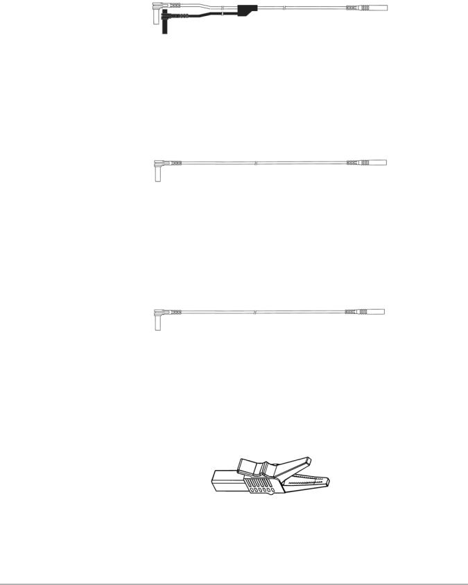
3.4.8 Secondary Ignition Clip-on Wire Adapter
Figure 3-10 Secondary Ignition Clip-on Wire Adapter
The Secondary Ignition Clip-on Wire Adapter (Figure 3-10) connects the Secondary Coil Adapter lead to the vehicle Secondary wire to display ignition patterns.
3.4.9 Inductive RPM Pickup Adapter
Figure 3-11 Inductive RPM Pickup adapter
The Inductive RPM Pickup adapter (Figure 3-11) connects to the AUX port with a DB9F plug to trigger a waveform or display RPM. When used with the Ignition Scope, it connects to cylinder number one to establish proper cylinder order.
14

|
Navigation |
Chapter 4 |
This section provides Lab Scope Plug-in navigation information. For detailed information on general MODIS™ navigation, refer to the MODIS™ Display User Manual.
4.1 Screen Layout
The Scope screens (Figure 4-1) include an upper toolbar, a main body, and a lower toolbar. Available buttons and controls vary depending on the active mode and stage of operation.
Figure 4-1 Sample Lab Scope Plug-in screen
1— Upper toolbar 2— Main body 3— Lower toolbar
4.1.1 Upper Toolbar
The upper toolbar controls vary depending on the module and stage of operations (Table 4-1).
Table 4-1 Upper toolbar controls (part 1 of 2)
|
Name |
|
Button |
|
|
Description |
|
||
|
View |
|
|
|
|
|
|
Lets you change the way data displays |
|
|
|
|
|
|
|
|
|
||
|
|
|
|
|
|
|
|
|
|
|
|
|
|
|
|
|
|
|
|
|
Pause |
|
|
|
|
|
|
Stops data collection and lets you review the |
|
|
|
|
|
|
|
|
|
||
|
|
|
|
|
|
|
buffered data |
|
|
|
|
|
|
|
|
|
|
|
|
|
|
|
|
|
|
|
|
|
|
|
|
|
|
|
|
|
|
|
|
|
|
|
|
|
|
15 |
|
|
|
Loading...