

Snap-On MUSCLE MIG SYSTEM MM350XL Owner's Manual
OWNER'S MANUAL
MM350XL M.I.G. COMBINATION UNIT
CONGRATULATIONS!
YOU HAVE PURCHASED THE WORLDS FINEST
MIG WELDING SYSTEM A V AILABLE EXCLUSIVEL Y FROM
SNAP-ON TOOLS. THE SNAP-ON MUSCLE MIG
SYSTEM MODEL# MM350XL IS DESIGNED AND
ENGINEERED BY THE PROS FOR THE PROS.
UNDER NORMAL CARE THIS SYSTEM WILL PROVIDE
YOU WITH YEARS OF UNSURPASSED SERVICE
AND MOST IMPORTANTLY PERFORMANCE.
FOR TECH. SERVICE, CALL TOLL-FREE 1-800-232-9353.
PROVIDE MODEL & SERIAL NUMBER.
INSTALLATION
OPERATION
MAINTENANCE
SAFETY - WELDERS SAFETY - WELDERS
DANGER
• Electric welding causes ultraviolet rays
and weld spatter.
Bystanders will be exposed to ultraviolet rays and weld spatter.
Wear welding helmet with appropriate
shade lens while using electric welders.
Do not allow bystanders while welding.
Wear safety shield and protective clothing (user and bystanders).
Read and follow instructions.
Ultraviolet rays will burn eyes; weld
spatter can cause injury.
WARNING
• Materials can cause sparks or flying metal
when heated which can cause fire.
Wear safety shield and protective clothing (user and bystanders).
Sparks, fire and flying metal can cause injury.
WARNING
• Electrical shock can result from absence
of grounding prong.
Do not remove or bypass the grounding
prong in any electrical plug.
Electrical shock can cause injury.
WARNING
• Smoke, fumes and gases are created by
the welding process.
Use only in well ventilated area.
Avoid breathing smoke, fumes and
gases.
Smoke, fumes and gases can cause injury.
WARNING
• Welded surface can be hot and cause
burns and injury.
2

MANUFACTURER’S LIMITED WARRANTY
This equipment is warranted against defects in materials and workmanship for a period of two years from the
date of purchase.
EXCEPTION: THE MIG TORCH IS WARRANTED FOR A PERIOD OF 30 DAYS FROM THE DATE OF
PURCHASE.
Should the equipment become defective for such reason, the Manufacturer will repair it without charge, if it
is returned to the Manufacturer’s factory, freight prepaid. This warranty does not cover: (1) failure due to normal
wear and tear; (2) consumable parts, such as, but not limited to, torch contact tips, gas cups and insulating
bushings; (3) damage by accident, force majeure, improper use, neglect, unauthorized repair or alteration; (4)
anyone other than the original purchaser.
THIS LIMITED WARRANTY IS IN LIEU OF ALL OTHER WARRANTIES, EXPRESS OR IMPLIED. THE
MANUFACTURER SHALL NOT BE LIABLE FOR ANY INJURY TO PERSONS, INCLUDING DEATH; OR LOSS
OR DAMAGE TO ANY PROPERTY, DIRECT OR CONSEQUENTIAL, INCLUDING, BUT NOT LIMITED TO,
LOSS OF USE, ARISING OUT OF THE USE, OR THE INABILITY TO USE, THE PRODUCT. THE USER
ASSUMES ALL RISK AND LIABILITY WHATSOEVER IN CONNECTION WITH THE USE OF THE PRODUCT,
AND BEFORE DOING SO, SHALL DETERMINE ITS SUITABILITY FOR HIS INTENDED USE, AND SHALL
ASCERTAIN THE PROPER METHOD OF USING IT.
SOME STATES DO NOT ALLOW LIMITATIONS ON HOW LONG AN IMPLIED WARRANTY LASTS, OR
THE EXCLUSIONS OR LIMITATIONS OF INCIDENTAL OR CONSEQUENTIAL DAMAGES. SO THE ABOVE
LIMITATIONS OR EXCLUSIONS MAY NOT APPLY TO YOU. THIS WARRANTY GIVES YOU SPECIFIC
LEGAL RIGHTS, AND YOU MAY HAVE OTHER RIGHTS WHICH MAY VARY FROM STATE TO STATE.
TABLE OF CONTENTS
SAFETY PRECAUTIONS ............................................................. 2
INTRODUCTION ........................................................................... 4
DESCRIPTION, SPECIFICATIONS .............................................. 5
CHECK LIST (CONTENTS) .......................................................... 6
INSTALLATION & ELECTRICAL REQUIREMENTS ................... 7
OPERATION ............................................................................... 12
WELDING .................................................................................... 14
MAINTENANCE ........................................................................... 16
TROUBLE SHOOTING CHART.................................................. 18
WIRE FEED CALIBRATION ....................................................... 22
CONNECTING FLEXTIG OR SPOOL GUN ............................... 23
LINER INSTALLATION ............................................................... 24
PARTS BREAKDOWN - MIG TORCH ........................................ 25
PARAMETER CHART ................................................................. 25
OPTIONS - FLEXTIG OR SPOOL GUN ..................................... 27
3
INTRODUCTION
The Snap-on Tools MM350XL is a
combination welding power source,
remote feed unit, MIG torch and
accessory package, which is designed to meet the requirements of
the light to heavy metal fabrication industries. The MM350XL produces fusion welds by the Gas Metal
Arc Welding process (GMAW or MIG),
on steel and aluminum up to "1/2"
thick, using .023" through 1/16"
steel wire and .023" through 3/64"
aluminum wire with the optional
MHG5-B spool gun. (optional liners
and drive rolls must be purchased to
cover all given wire types and
sizes). Heavier sections can be
easily welded using slightly different techniques.
The number of controls on the unit
have been reduced to assist inexperienced operators to learn MIG
welding. This facilitates rapid
set up for welding various thicknesses of material requiring various heat inputs. The VOLTAGE
control adjusts the welding voltage
and the WIRE FEED control adjusts
the speed of the wire feed motor.
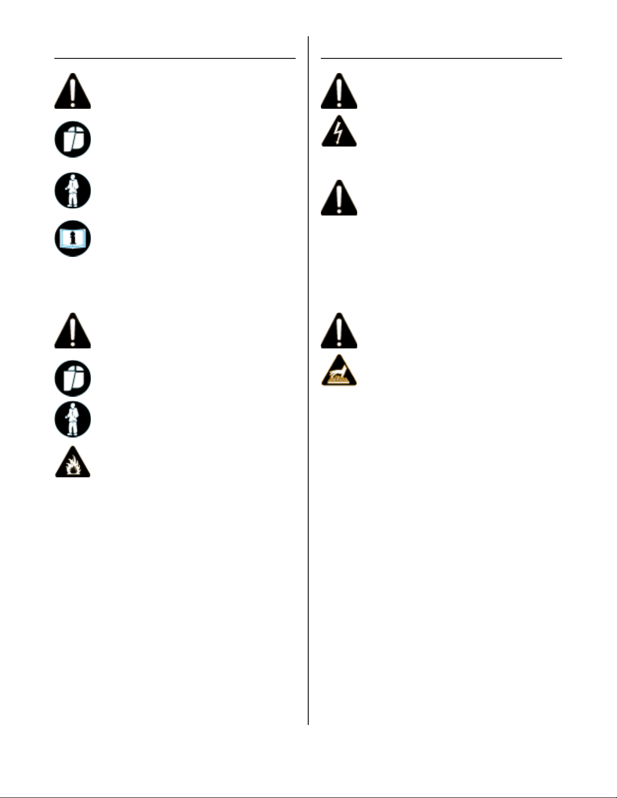
THE MIG PROCESS
AS APPLIED TO THE MM350XL
The MIG process uses a bare,
consumable electrode in the form of
spooled wire, which is fed by a
controllable speed feed unit
through the cable and torch to the
weld. The emerging wire and the
weld are shielded by a stream of
CO2, Argon, or a mixture of the two,
which prevents oxidation of the
molten weld puddle. The gas shield
enables high quality welds to be
made without the use of flux,
eliminating the need for slag or
flux removal after the weld is
completed.
WIRE SPOOL
FEED
ROLLS
MIG
TORCH
POWER SOURCE
+
REVERSE
POLARITY
SHIELDING GAS
WORK
FIG. 1. SCHEMATIC OF M.I.G. PROCESS
(STD.)
_
The consumable electrode wire is
melted and transferred to the weld
puddle by any of three arc modes;
short arc transfer, globular transfer, or spray arc transfer. The
MM350XL is capable of performing
all modes.
SHORT ARC OR DIP TRANSFER
Short arc transfer occurs at 12 to
22 arc volts (voltage while welding), depending on wire size. Welding commences as the arc is struck
and a weld pool is formed. The tip
of the electrode wire dips into the
pool and causes a short circuit.
The short circuit current flow
causes a rapid temperature rise in
the electrode wire and the end of
the wire is melted off. An arc is
immediately formed between the tip
of the wire and the weld pool,
maintaining the electrical circuit
and producing sufficient heat to
keep the weld pool fluid. The
electrode continues to feed and
again dips into the pool.
ELECTRODE
WORK
FIG. 2. SHORT ARC TRANSFER
4
SHORT ARC OR DIP TRANSFER (Cont.)
DESCRIPTION
This sequence of events is repeated up to 200 times per second.
Short arc transfer is suitable for
positional welding. The heat input
to the workpiece is kept to a
minimum which limits distortion and
makes possible the welding of thin
sheet material.
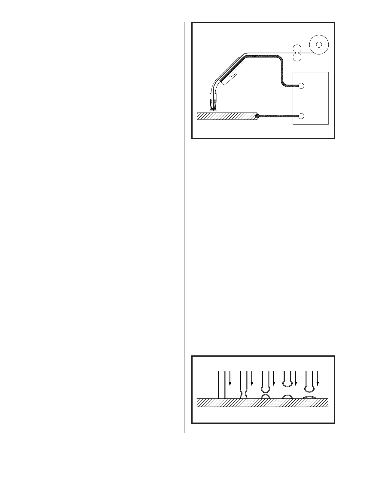
GLOBULAR TRANSFER
Globular transfer occurs at the
intermediate range of 22 to 24 arc
volts, depending on wire size. As
the name implies, the transfer
takes place in the form of irregularly shaped globules. Globular
transfer is useful in cases where a
lower heat input than that of true
spray is required.
ELECTRODE GAS NOZZLE
SHIELDING GAS
WORK
The MM350XL consists of a combi-
nation MIG welding power source and
remote feed unit, a MIG torch with
twelve foot cable, a fifteen foot
feeder control cable, a twenty-five
foot work cable with clamp, a twenty
foot power input cable, a gas
regulator - flowmeter, a torch
accessory kit, built-in storage
compartment and a dual cylinder
rack and industrial wheel kit.
Welder controls are simple and
clearly marked. The output voltage
is controlled by a twelve position
tap switch, providing 4 TIG and 8
MIG voltage selections. Wire feed
speed is controlled by the wire
speed potentiometer on the front of
the feed unit.
SPECIFICATIONS
PART NUMBER: MM350XL
FIG. 3. GLOBULAR TRANSFER
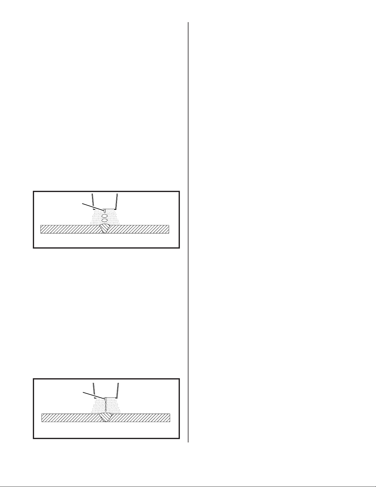
SPRAY TRANSFER
Spray transfer occurs at 22 to 32
arc volts, depending on wire size.
The length of the arc is held
constant by the voltage available.
The higher voltage and current
causes the electrode wire to melt
off before touching the workpiece.
The molten metal crosses the gap to
the workpiece in a spray form.
Spray transfer is used in the downhand position and provides higher
deposition rates than short arc
transfer or globular transfer.
ELECTRODE GAS NOZZLE
SHIELDING GAS
WORK
INPUT POWER REQUIREMENTS:
Voltage 208/230
Phase single phase
Frequency 50/60 hertz
Current 46/42
DUTY CYCLE - OUTPUT POWER:
@ 100% - 300 Amps
@ 60% - 350 Amps
DUTY CYCLE TIME PERIOD:
10 minutes
OPEN CIRCUIT VOLTAGE:
18 - 42 volts DC
ARC VOLTAGE: 12 - 32 volts DC
WELD CURRENT RANGE:
30 - 350 amps
REMOTE FEED UNIT
Input Voltage 28 VAC
Wire Feed Speed Range: 50-800 IPM
FIG. 4. SPRAY TRANSFER
(continued on following page)
5

SPECIFICATIONS (Cont.)
CHECK LIST
WIRE TYPES: mild steel,
stainless steel, aluminum,
bronze, flux cored,
flux cored - gasless
Recommended (for steel) ER70S-
WIRE SIZES: .023" - 1/16" steel,
3/64 - 1/16" aluminum,
(.023" - 3/64" alum. w/spool gun)
.030" - .035" bronze,
.035" - .045" flux cored
(gas shielded or gasless)
Recommended Size:Aluminum .035
Others .035
SHIELDING GASES:
For Steel CO2 or Argon/CO2 mix
Recommended (for steel) 75% Argon/
25% CO2
For Aluminum, Bronze 100% Argon
For Stainless Steel
98% Argon/2% Oxygen
For Flux cored CO2 or
Argon/CO2 mix
THE SNAP-ON TOOLS MM350XL INCLUDES
THE FOLLOWING:
1- Combination Power Source/Remote
6
Feed Unit.
1- Dual Cylinder Rack & Industrial
Wheel Kit.
1- FCA-15X 15 foot Feeder Control
Cable assy.
1- 35XL12 12 foot MIG Torch with
adjustable nozzle.
1- 20CP-3M 20 foot Power Input
Cable.
1- SN-178X521 25 foot Work Cable
and 500 amp clamp.
1- 350LPK Parts Kit.
1- GR-FM Gas Regulator/Flowmeter.
1- ER70S-6-35-3, Sample Spool of
.035 Steel Wire.
1- 8IN-A 8 inch Reel Adapter.
ITEMS REQUIRED FOR MIG WELDING
WHICH ARE NOT PROVIDED WITH THE
MM350XL
DIMENSIONS:
Height 35-3/4 in.(90.8 cm.)
Width 27-1/4 in.(69.2 cm.)
Depth 34-1/2 in.(87.7 cm.)
Weight 275 lbs.(124.9 kg.)
TORCH SPECIFICATIONS
NECK ANGLE: 60 degrees
LEAD LENGTH: 12 feet
OVERALL LENGTH: 12 feet
COOLING METHOD: gas (air)
RATING - DUTY CYCLE:
With Argon/CO2 gas 250 amps @ 100%
With CO2 gas 300 amps @ 100%
1. Full cover welding helmet with
proper colored lens (shade 9 to
11 depending on operator’s pref-
erence).
2. Proper shielding gas and cylin-
der.
3. Leather welding gloves.
4. Electrical power and matching
electrical plug.
THE MM350XL REQUIRES A 208
OR 230 VOLT, SINGLE PHASE,
AC, 60 AMP CIRCUIT
5. Other personal protective
equipment which may vary to
match the welding being per-
formed.
6
INSTALLATION
POSITIONING THE UNIT
Locate the unit adjacent to the
welding area and position it so
there is adequate clearance all
around for ventilation and maintenance.
WARNING
• Smoke, fumes and gases are created by
the welding process.
Use only in well ventilated area.
Avoid breathing smoke, fumes and
gases.
Smoke, fumes and gases can cause injury.
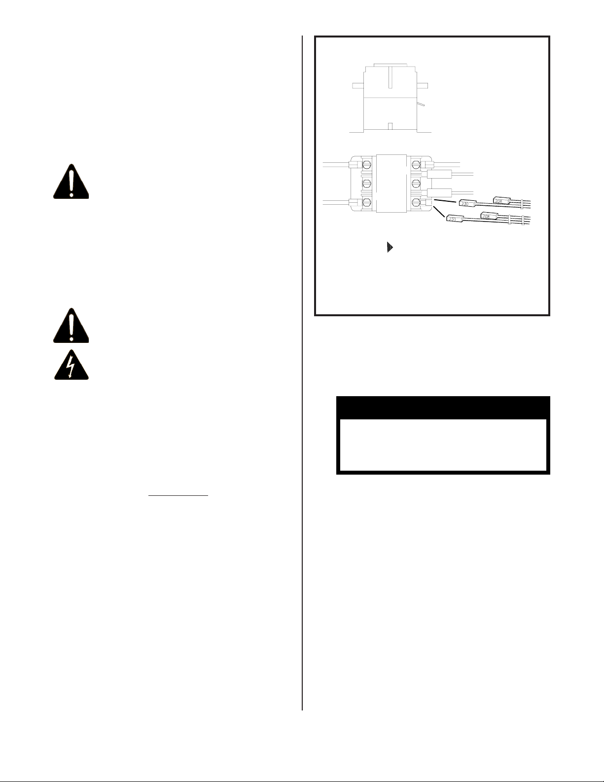
ELECTRICAL SUPPLY
CONTACTOR SWITCH
CONNECT "208"
WIRE FOR
OPERATION ON
208 VOLT INPUT
CONNECT
FRONT OF
MACHINE
FIG. 5. INPUT VOLTAGE SELECTIONS
"230" WIRE FOR
OPERATION ON
230 VOLT INPUT.
WARNING
• Electrical shock can result from absence
of grounding prong.
Do not remove or bypass the grounding
prong in any electrical plug.
Electrical shock can cause injury.
Ensure that there is a 208 or 230
volt, single phase, 60 amp electrical
supply within easy reach of the
unit. The input cable supplied is 20
feet long.Attach a suitable plug
making sure the green wire is attached to
the ground terminal of the wall plug. All
wiring should be performed by a
qualified electrician.
230V INPUT SELECTION
1. Factory selected no change is
needed.
208V INPUT SELECTION
1. Remove the left side panel.
2. Locate the contactor switch,
which is mounted on top of the
main power transformer(See Figure 5).
CAUTION
MAKE SURE POWER SOURCE IS
UNPLUGGED BEFORE MAKING INPUT SELECTION CHANGE-OVER.
3. Attached to the power source’s
contactor are two (2) two position plugs which allows easy
selection of input voltages of
either 208 or 230 volts.
4. Remove both plugs labeled 230V
and connect the two (2) plugs
labeled 208V.
5. Reattach the left side panel of
the machine. Voltage input selection is now complete.
(continued on following page)
7
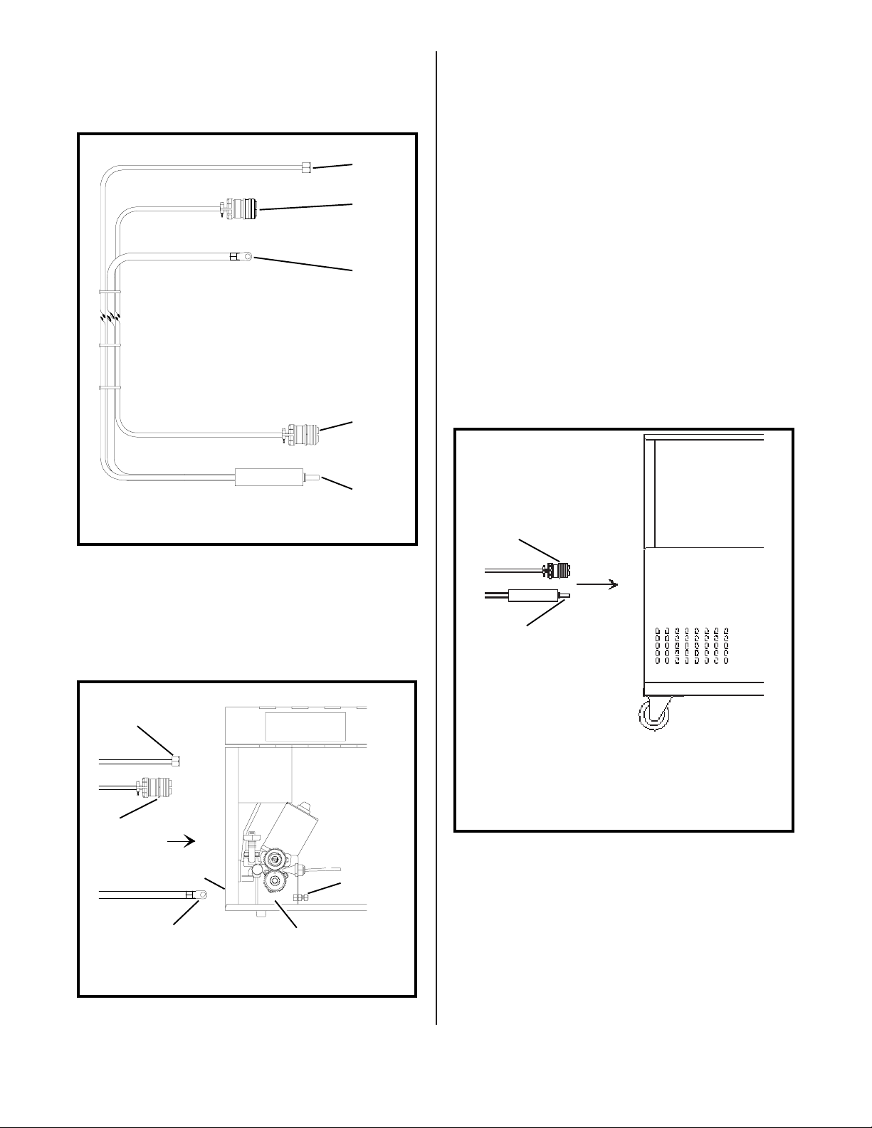
INSTALLING THE FEEDER CONTROL CABLE
ASSEMBLY
1. Uncoil the cable assembly.
3. With the proper size wrench
attach the gas fitting to the gas
terminal (located on the front
of the feed unit).
GAS HOSE
CURRENT
CABLE
FEED
CABLE
ASSEMBLY
CONTROL
CABLE
FIG. 6. FCA-15X FEEDER CABLE ASSEMBLY
GAS
FITTING
CONTROL
PLUG
(FEMALE
PINS)
CURRENT
LUG
CONTROL
PLUG
(MALE
PINS)
POWER
PLUG
4. Connect the control plug (female
pins)onto the control receptacle (INPUT) and tighten (located on the front of the feed
unit).
5. Plug the power plug into the
positive (+) terminal(located
on the front of the welding
machine).
6. Connect the control plug (male
pins) onto the control receptacle (OUTPUT)and tighten (located on the front of the welding
machine).
TO CONTROL
RECEPTACLE
(OUTPUT)
2. Insert the current lug through
the hole on the front of the feed
unit and with the proper size
wrench fasten it to the input
current stud, located on the
back side of the drive bracket.
TO GAS
TERMINAL
FEED
UNIT
TO
CONTROL
RECEPTACLE
(INPUT)
FIG. 7. CABLE CONNECTION TO FEED UNIT
CABLE
HOLE
TO CURRENT
STUD
INPUT
CURRENT
STUD
DRIVE
BRACKET
WELDING
MACHINE
TO (+)
TERMINAL
(STANDARD)
FIG. 8. CABLE CONNECTION TO
WELDING MACHINE
SHIELDING GAS CONNECTIONS
1. Place a cylinder of the appropriate shielding gas in the rack
at the rear of the machine and
secure it with the chain provided.
8
2. Rapidly open and close the cylinder valve. This will purge
dust and foreign matter from the
valve.
CAUTION
4. Fit the gas hose from the welding
machine to the regulator outlet
fitting and tighten it with a
wrench. Open the cylinder valve.
When welding steel, the gas flow
rate is 30 CFH.
Take care to point the
valve outlet away from
yourself or other people,
as escaping high pressure
gas may be dangerous.
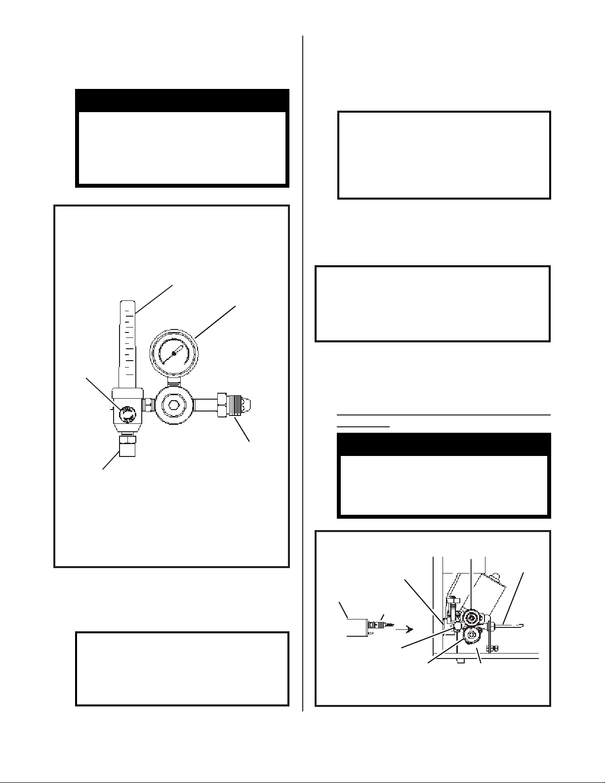
GAS FLOW
ADJUSTING
KNOB
FLOW TUBE
INDICATES
FLOW RATE
IN C.F.H.
GAUGE -
INDICATES
TANK
PRESSURE
NOTE
The MM350XL must be turned
"ON" and the MIG torch
trigger depressed, before
the gas flow rate can be
adjusted.
TORCH CONNECTION
1. Open the access door of the Feed
unit to its fullest extent.
NOTE
Prior to inserting the MIG
torch into the torch panel
mount, apply anti-spatter
spray to the "O" rings.
2. Back out the thumb screw located
on the drive bracket inside the
machine. Insert the MIG torch
into the torch panel mount and
TIGHTEN THE THUMB SCREW SECURELY.
INLET
FITTING
TO
OUTLET
FITTING
TO
WELDING
MACHINE
FIG. 9. GAS FLOW ADJUSTMENT
TANK
3. Attach the gas regulator - flowmeter supplied with this unit,
to the cylinder valve using a
suitable wrench.
NOTE
If this unit is to be used
with 100% CO2 shielding
gas, an optional gas regulator coupler is required.
MIG
TORCH
WARNING
SEVERE DAMAGE TO THIS
PRODUCT MAY RESULT.
TIGHTEN THUMB SCREW BEFORE EACH USE.
PRESSURE
TORCH
PANEL
MOUNT
"O"
RINGS
THUMB
SCREW
DRIVE
ROLL
FIG. 10. TORCH CONNECTION
ROLL
DRIVE
BRACKET
INLET
GUIDE
9
 Loading...