

Page 1

200 AMP PULSE MIG WELDER
MIG200i
INTRODUCTION
The MIG200i Pulse is a 230VAC single-phase synergic inverter power source for MIG welding. This
versatile power source is suitable for various applications from general repairs to speci c material
types used in the body shop industry. Welds a variety of material types and thicknesses such as
steel, stainless-steel, aluminum, high strength and boron steels. Preset synergic curves automatically provide proper settings for individual situations and reduce set up times.
3301025
Page 2

TABLE OF CONTENTS
Introduction ....................................................................................................................................................Front Cover
Table of Contents ............................................................................................................................................................2
Safety Information ....................................................................................................................................................... 3-4
Specications ..................................................................................................................................................................5
Features ...........................................................................................................................................................................6
Description of Equipment ................................................................................................................................................6
Assembling the Unit .................................................................................................................................................... 7-9
Quick start guide ....................................................................................................................................................... 9-11
Advanced setting .................................................................................................................................................... 11-14
Maintenance ..................................................................................................................................................................15
Replacement Parts .................................................................................................................................................. 16-18
Wiring Diagram ..............................................................................................................................................................19
Warranty/Service and Repair.........................................................................................................................................20
2
Page 3
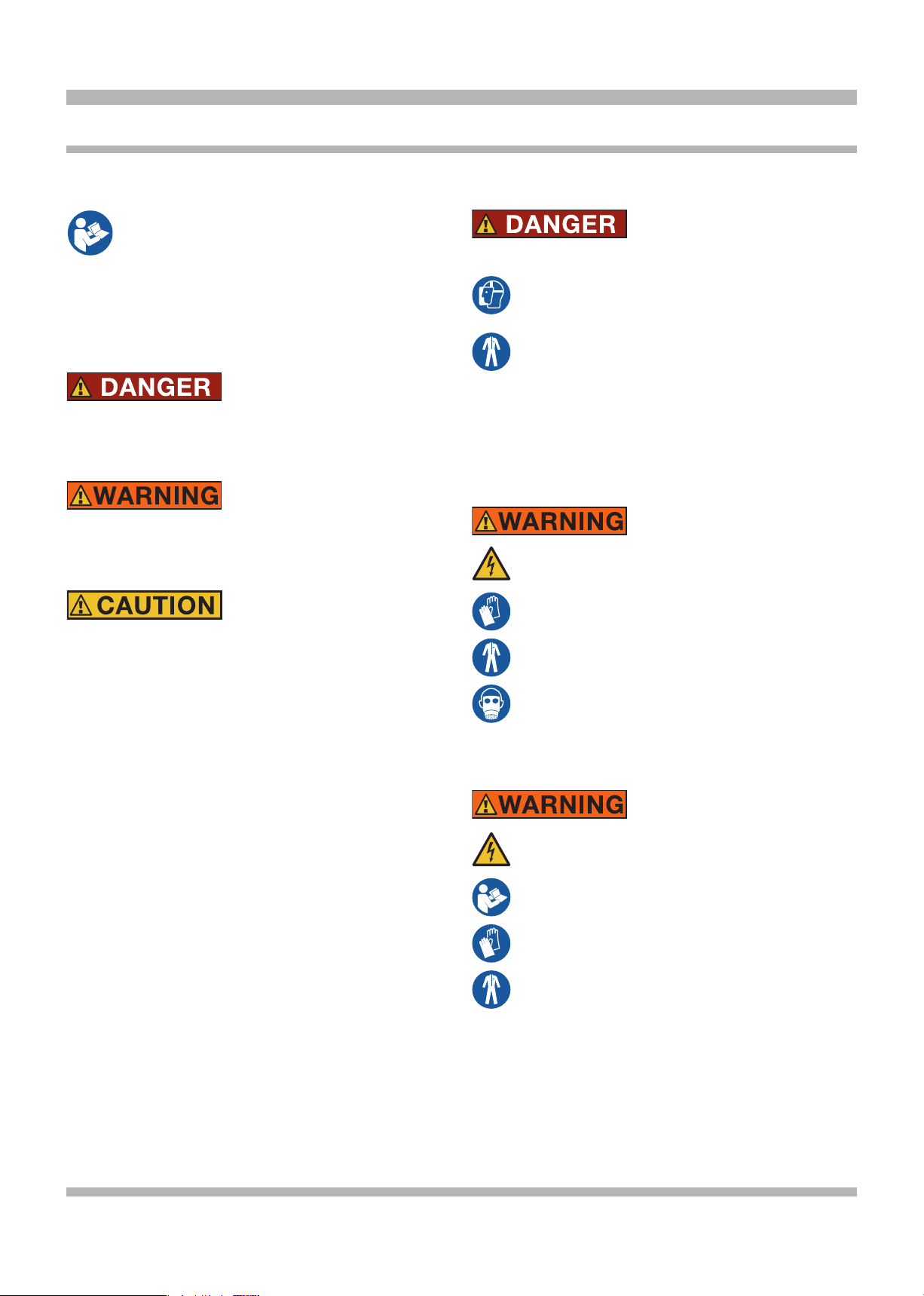
SAFETY INFORMATION
MUST READ INSTRUCTIONS BEFORE USE
Read, understand and follow all safety messag-
es and instructions in this manual. Safety messages in this section of the manual contain a signal word with a three-part message and, in some
instances, an icon.
The signal word indicates the level of the hazard in a situation.
Indicates an imminently hazardous situation which, if not
avoided, will result in death or serious injury to the operator or bystanders.
Indicates a potentially hazardous situation which, if not
avoided, could result in death or serious injury to the operator or bystanders.
Indicates a potentially hazardous situation which, if not
avoided, may result in moderate or minor injury to the
operator or bystanders.
IMPORTANT
Indicates a situation which, if not avoided, may result in
damage to the welding equipment.
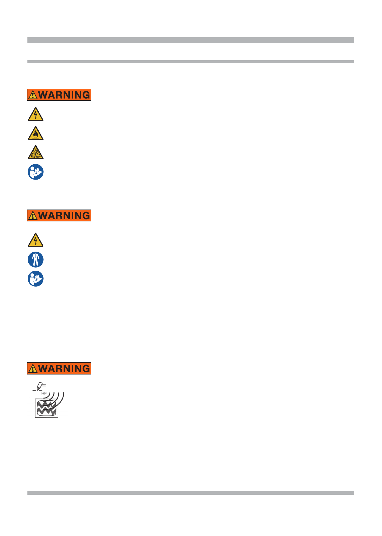
Arc Welding
Electric welding or plasma cutting causes ultraviolet rays and weld spatter.
Bystanders will be exposed to ultraviolet rays
and weld spatter.
Wear welding helmet with appropriate shade
lens while using electric welders or plasma
cutters.
Do not allow bystanders while welding or
cutting.
Wear safety shield and protective clothing.
Ultraviolet rays will burn eyes; weld spatter can
cause injury.
Welding produces heat, sparks, hazard of electric shock and/or hazardous vapors
Wear appropriate gloves, helmets or goggles
and other protective clothing.
Follow all instructions and safe practices
while welding or cutting.
Keep bystanders away from immediate area.
Byproducts of welding can cause burns or other
bodily injury.
Risk of Electrical Shock
Safety messages in this section contain three different
type styles.
• Normal type states the hazard.
• Bold type states how to avoid the hazard.
• Italic type states the possible consequences of not
avoiding the hazard.
An icon, when present, gives a graphical description of
the potential hazard.
Electrical shock can result when contacting live
electrode or internal components
Electrical shock can result from absence of
grounding lug.
Welding machine must be connected to
power source in accordance with applicable
electrical codes.
Do not touch electrode or internal components without protection.
Disconnect power before servicing.
Do not remove the grounding lug in any electrical plug.
Electrical shock can cause injury.
3
Page 4
SAFETY INFORMATION cont'd
Risk of Explosion
Welding causes sparks that can cause explosion.
Use caution and proper procedures when
welding.
Avoid sparks if gasoline vapor and other fuels
are present.
Electrical shock, ames and explosion can cause
serious injury.
Electrical and Magnetic Fields
Welding may cause localized electrical and mag-
netic elds araund cables and power sources.
The magnetic elds created by high currents
may affect the operation of medical equipment.
Route the electrode and work cables together.
Do not place your body between the electrode/torch and work cables.
Never coil the electrode/torch lead around
your body.
Do not work next to welding/cutting power
source.
Electrical shock and Magnetic elds can cause
injury.
Disposal of Equipment
IMPORTANT
Disposal of electrical equipment can be hazardous to the environment.
Contact local regulations prior to disposal.
Improper disposal can cause an environmental
hazard.
FUMES AND GASES can be dangerous to your
health.
ITEMS REQUIRED FOR MIG WELDING WHICH ARE
NOT PROVIDED WITH THE MIG185i.
1. Full cover welding helmet with proper colored lens
(shade 9 to 11, depending on operator's preference).
2. Proper shielding gas and cylinder.
3. Leather welding gloves.
4. 230 volt single phase 30 Amp AC power.
5. Other personal protective equipment, which may vary
to match the welding being performed.
SAVE THESE INSTRUCTIONS
H.F RADIATION can cause interference
• High frequency (H.F.) can interfere with
radio navigation, safety services, computers, and communications equipment.
• Have only qualied persons familiar with
electronic equipment perform this installation.
• The user is responsible for having a qualied electrician promptly correct any interference problem resulting
from the installation.
• If notied by the FCC about interference, stop using the
equipment at once.
• Have the installation regularly checked and maintained.
• Keep high-frequency source doors and panels tightly
shut, keep spark gaps at correct setting, and use grounding and shielding to minimize the possibility of interference.
4
Page 5
1
~
f
1
f
2
SPECIFICATIONS
GENERAL DESCRIPTIONS
This welding machine is a power source developed with
inverter technology, suitable for MIG welding.
This welding machine must not be used to defrost pipes.
EXPLANATION OF TECHNICAL SPECIFICATIONS
LISTED ON THE MACHINE PLATE
This machine is manufactured according to the following
international standards:
IEC 60974-1 / IEC 60974-10 (CL. A) / IEC 61000-3-11 /
IEC 61000-3-12.
No. Serial number. Must be indicated on any re-
quest regarding the welding machine.
Single-phase static transformer-rectier
frequency converter.
MIG Suitable for MIG/MAG welding.
U0. Secondary open-circuit voltage.
X. Duty cycle percentage.
The duty cycle expresses the percentage of
10 minutes during which the welding machine may run at a certain current without
overheating.
I2. Welding current
U2. Secondary voltage with I2 current
U1. Rated supply voltage.
1~ 50/60Hz Single-phase 50 or 50 Hz power supply.
I1 Max Max. absorbed current at the corresponding
I2 current and U2 voltage.
I1 eff This is the maximum value of the actual cur-
rent absorbed, considering the duty cycle.
This value usually corresponds to the capac-
ity of the fuse (delayed type) to be used as a
protection for the equipment.
IP23S Protection rating for the housing. Grade 3
as the second digit means that this machine
may be stored, but it is not suitable for use
outdoors in the rain, unless it is protected.
Suitable for use in high-risk environments.
S
NOTE:
The equipment has also been designed for use in environments with a pollution rating of 3. (See IEC 60664).
SPECIFICATIONS
Power Input
Voltage 230 Volt
Phase Single Phase
Frequency 50/60 Hertz
Current 26 Amps
Power Output
Duty Cycle/Rated Output 100% @ 120 Amps
60% @ 140 Amps
20% @ 200 Amps
Output Control Adjustable 20 - 200 Amps
Torch Cable Length 10 Feet
Ground Cable Length 10 Feet
Power Input Cord 9 Feet
Dimensions
Height 16 Inches
Width 11 Inches
Depth 19 Inches
Weight
Base Unit 46 lb
Shipping 50 lb
PROTECTION DEVICES
Block protection
In case of a welding machine malfunction, the display
A
screen
will show the message WARNING to identify
the type of fault. If this message does not disappear when
the machine is switched off and back on, contact service
at 800-ABC-WELD.
Thermal cutout
This unit is protected by a thermostat which prevents
machine operation whenever acceptable temperatures
are exceeded. In these conditions, the fan continues to
operate and the display screen A shows the message
WARNING tH in ashing mode.
5
Page 6
FEATURES
• Compact inverter-style wire feed synergic MIG welder.
• Easy to read LCD display panel and single-knob for selection and adjustments.
• Multiple synergic curves allow you to weld a variety of materials and thicknesses.
• Preset synergic curves automatically provide the proper settings to each individual situation.
• Individual welding parameters and preset by material, thickness, wire type and size along with shielding gas type.
• LCD screen shows welding parameters such as current, voltage, recommended thickness, wire speed and wire diameter.
• Machine automatically sets heat, wire speed for multiple material thicknesses.
• MIG welding of steel, stainless-steel and MIG brazing of high-strength and Boron steels.
• Welds 5356 and 4047 aluminum with standard torch kit,optional steel torch MIG1855
• Spot weld and pause features with adjustable on time.
• Adjustable arc length, inductance, burnback and soft arc starting.
• Faster set up time and reduced production times.
• Over 30 years of industry-leading technical support by calling 800-ABC-WELD
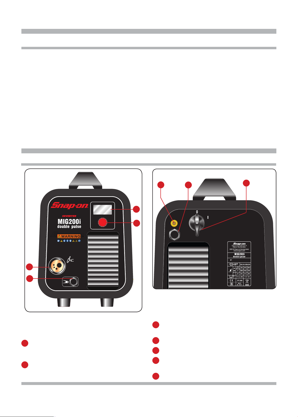
DESCRIPTION OF EQUIPMENT
E
A
B
C
D
G
F
A
DISPLAY SCREEN
This displays both the welding parameters and
welding functions.
B
MULTI-FUNCTION KNOB
Selects and adjusts both the welding functions and
parameters.
C
CENTRALIZED COUPLING
Welding torch connection.
D
GROUND LEAD
E
GAS SUPPLY CONNECTION
F
POWER SWITCH
Turns the machine off and on.
G
POWER INPUT CORD
6
Page 7

ASSEMBLING THE UNIT
Position the welding machine so as to allow the free circulation
of air inside and, as much as possible, prevent metal or other
dusts from penetrating.
• Electrical supply: ensure that there is a 208 or 230 volt,
single phase, 30 ampere electrical supply within easy reach
of the unit. The input cable supplied is 9 feet long.
Attach a suitable plug making sure the green yellow wire is
attached to the ground terminal of the wall plug. All wiring
should be performed by a qualied electrician
• The machine must be installed by professional personnel.
• All the connections must be performed in compliance
with applicable standards (IEC/CEI EN 60974-9) and with
accident-prevention laws.
• Make sure the power supply voltage corresponds to the
welding machine rating.
• The protection fuses must be sized according to the details
shown on the technical data plate.
Make sure the ground wire
compartment, is connected to the negative pole
coming out of the dividing wall.
Alongside the two terminals is positioned a plate, which
explains the correct polarity to be used with cored wire
without gaseous protection or a wire with gaseous
protection.
Connect the ground lead clamp
Open the side door. Install the wire reel according to the
instructions provided below.
NOTE: The wire feed motor is inoperative if hinged
side panel is open
D
, inside the reel
D
to the piece to be welded.
REEL FITTING SEQUENCE
fig.7 fig.8
Electrical shock can result when contacting live
electrode or internal components
Electrical shock can result from absence of
grounding lug.
Welding machine must be connected to
power source in accordance with applicable
electrical codes.
Please refer to the troubleshooting tip section located at our web site (www.800ABCWELD.com) for information on wiring the
230 V plug if needed.
Do not touch electrode or internal components without protection.
Disconnect power before servicing.
Do not remove the grounding lug in any electrical plug.
REEL FITTING SEQUENCE
fig.3 fig.4
fig.5
fi g .1
fig.2
fig.6
Electrical shock can cause injury.
During wire installation, the welder must be switched
off and unplugged to prevent the motor roller from
movingpresenting a risk for the operator.
• Fit the reel on the support inside the compartment as
shown in g. 1.
• The reel must be tted on the support so the wire
unwinds in an clockwise direction. It is important for
the wire to be stopped on the reel on the visible side,
see g. 2. Block the reel on the support, as shown in
the illustration.
• Make sure the drive roller is correctly positioned
according to the diameter and type of wire used. To
remove the roller, align the at part of the roller-bearing
pin at the bottom, so the key can be tted inside the
retention screw. Loosen the screw, remove the roller, t
the roller back on so the race corresponds to the wire
used, see gures 3 and 4.
• Cut the wire with a well-sharpened tool, keeping it
between your ngers so that it cannot unwind, insert it
inside the plastic pipe exiting from the gear motor and,
with the aid of a nger, also insert it inside the brass
adapter, see gures 5-6-7-8.
7
Page 8

ASSEMBLING THE UNIT cont'd
• Close the drive arm, being careful of the wire, which
must be aligned with the roller race,.
• Fit the welding torch.
After tting the reel and torch, switch on the machine, select
the suitable synergic curve, following the instructions given
in the service functions (PROCESS PARAMS) paragraph.
Remove the gas nozzle and unscrew the contact tip of
the torch. Press the torch button until the wire comes out
.
Electrical shock can result when contacting live
electrode or internal components
Electrical shock can result from absence of
grounding lug.
Welding machine must be connected to
power source in accordance with applicable
electrical codes.
Do not touch electrode or internal components without protection.
Disconnect power before servicing.
Do not remove the grounding lug in any electrical plug.
Electrical shock can cause injury.
SET-UP FOR STEEL WELDING
•Insert the wire guide
tube supplied along with
the welding machine inside the torch adapter
C
.
• Replace the wire feed roller (see g. 3), with the roller
suitable for the steel wire you have to weld.
• Install the torch prepared for steel.
MIG WELDING WITHOUT GAS
Install the contact tip and gas nozzle.
Open the tank valve and adjust the gas ow to 20-30 CFH
(8/10 l/min) using the ow meter regulator.
During welding, the display screen
actual work current and voltage. The displayed values
may be slightly different to those set. This can depend
on numerous different factors-type of torch, thickness
different to nominal thickness, distance between contact
tip the material being welded, and the welding speed.
At the end of the weld, the current and voltage values
remains in memory in the display
values, slightly turn the knob
If you press the knob
shows the open circuit voltage (=0).
B
B
.
without welding, the display
A
displays the
A
; to view the set
A
Install a reel of ux cored wire for welding without gas
and select the adequate synergic curve (E71TGS 0.35"),
following the instructions described in the “service
functions (PROCESS PARAMS) paragraph.
Extended welding with ux cored wire will cause the end
of the torch to get hot. This could melt the cover and end
of the torch.
Fit the wire roller suitable to the 0.035" diameter ux cored
wire and the current nozzle on the welding torch.
Connect the terminal of the ground lead, inside the
reel compartment, to the positive pole, while the lead
coming out of the dividing wall must be connected to
the negative pole.
Connect the ground lead clamp to the piece to be
welded.
DIFFERENT TYPES of WIRE
• Flux cored wire
This is typically used for outdoor repairs on steel struc-
tures, for thicknesses of .039" to .240".
• Steel (Fe), with either ArCO2 or CO2
The different curves allows to weld on steel structures
with a thickness of .024" to .236".
Consequently these curves are widely used in the car
body repair, as well as for other small repairs of steel
structures.
8
Page 9

ASSEMBLING THE UNIT cont'd
• Stainless Steel 308L
This is typically used to repair many applications in-
cluding stainless steel tanks and containers with a
thickness of .031" to .177".
• Aluminum (AlMg5-5356 and AlSi12-4047)
It is possible to weld on thicknesses of .031" to .276".
Therefore this is widely used in the car body repair, but
also to repair boats and other aluminum structures.
• CuSi3 (Silicon Bronze) MIG Brazing
It is possible to work on galvanized sheets of .024" to
.197".
The main applications is therefore the car body repair,
but it can also be used for repairing other galvanized
structures within the maximum thickness.
QUICK START GUIDE
1- TURN ON THE WELDER USING THE ON/OFF
SWITCH.
When the machine is
switched on, for a few
moments the display screen
A
displays: the model
number of the machine, the
version and development
date of the software, and the release number of the
synergic curves.
A
The display screen
used, the start mode
2T, 4T ,3L the welding current, the speed of the welding
wire in inches/min, the welding voltage, the thickness of
metal to weld in inches and the welding process
will then show the synergic curve
short
MIG
To increase or decrease the welding parameters, simply
adjust by means of knob
together in a synergic way.
2- SET THE WIRE SIZE AND WELDING GAS
To access these functions, we must start from the main
display page and press the knob
To enter the function, simply select it by means of the knob
B
and press it for less than 2 seconds. To return to the main
display page, press the knob
Select the wire material, wire size and shielding gas to be
used. Return to the main menu by pushing the knob for
at least 2 seconds.
3- SET THE THICKNESS OF THE METAL BY TURNING
KNOB B
or pulse
MIG
B
. The values all change
B
for at least 2 seconds.
B
for at least 2 seconds.
9
Page 10

QUICK START GUIDE cont'd SYNERGIC CURVE (WIRE SELECTION)
Setting Wire Composition
E71TGS .035 Flux Core - Steel none
Fe .023” Steel 75% Argon
Fe .023” Steel 100% CO2 .024”-.157”
Fe .030” Steel 75% Argon
Fe .030” Steel 100% CO2 .024”-.197”
Fe .035” Steel 75% Argon
Fe .035” Steel
Fe .040” Steel
Fe .040” Steel
308L .030” Stainless-Steel
308L .035” Stainless-Steel
308L .040” Stainless-Steel
AlMgMn2.7
5554
AlMgMn2.7
5554
AlMg5
5356
AlMg5
5356
AlMg5
5356
AlSi12
4047
AlSi12
4047
AlSi12
4047
AlSi12
4047
CuSi3
6560
CuSi3
6560
CuSi3
6560
Union x 96 .030” Steel
Union x 96 .030” Steel
.040” Aluminum
Magnesium 2.7%
.045” Aluminum
Magnesium 2.7%
.030” Aluminum
Magnesium 5%
.035” Aluminum
Magnesium 5%
.040” Aluminum
Magnesium 5%
.023” Aluminum
Silicon 12%
.030” Aluminum
Silicon 12%
.035” Aluminum
Silicon 12%
.040” Aluminum
Silicon 12%
.030” Copper
Silicon 3%
.035” Copper
Silicon 3%
.040” Copper
Silicon 3%
Shielding
Gas
25% CO2
25% CO2
25% CO2
100% CO2
75% Argon
25% CO2
100% CO2
98% Argon
2% CO2
98% Argon
2% CO2
98% Argon
2% CO2
100% Argon
100% Argon
100% Argon
100% Argon
100% Argon
100% Argon
100% Argon
100% Argon
100% Argon
100% Argon
100% Argon
100% Argon
Argon +
2 18%
CO
Argon +
CO
2 18%
Material Thickness
MIN/MAX inch
SHORT PULSED
.039 - .240
1 – 6 mm
.024”-.118”
0.6 - 3mm
0.6 - 4mm
.024”-.197”
0.6 - 5mm
0.6 - 5mm
.031”-.197”
0.8 - 5mm
.031”-.165”
0.8 – 4.2mm
.031”-.150”
0.8 – 3.8mm
.031”-.268”
0.8 – 6.8mm
.031”-.157”
0.8 - 4mm
.039”-.263”
1.0 – 6.7mm
.035”-.276”
0.9 – 6.7mm
.039”-.236”
1.0 – 6mm
.047”-.157”
1.2 – 4mm
.031”-.197”
0.8 - 5mm
.031”-.236”
0.8 - 6mm
.035”-.315”
0.9 - 8mm
.024”-.098”
0.6 – 2.5mm
.031”-.197”
0.8 - 5mm
.039”-.315”
1.0 - 8mm
.039”-.236”
1.0 - 6mm
.024”-.118”
0.6 - 3mm
.024”-.157”
0.6 - 4mm
.028”-.197”
0.7 - 5mm
.024”-.197”
0.7 - 5mm
.024”-.197”
0.7 - 5mm
Application
All-purpose steel welding from sheet metal
to structural
.028”-.138”
0.7 – 3.5mm
--- All-purpose steel welding from thin sheet
.031”-.158”
0.8 - 4mm
--- All-purpose steel welding from thin sheet
.031”-.197”
0.8 - 5mm
--- All-purpose steel welding from thin sheet
.031”-.197”
0.8 - 5mm
--- All-purpose steel welding from thin sheet
.024”-.181”
0.6 – 4.6mm
.031”-.209”
0.8 – 5.3mm
.031”-.197”
0.8 – 5mm
.031”-.197”
0.8 – 5mm
.039”-.217”
1 – 5.5mm
.031”-.236”
0.8 - 6mm
.031”-.236”
0.8 - 6mm
.031”-.217”
0.8 – 5.5mm
.031”-.157”
0.8 - 4mm
.024”-.236”
0.6 - 6mm
.024”-.236”
0.6 - 6mm
.031”-.236”
0.8 - 6mm
.031”-.142”
0.8 – 3.6mm
.031”-.197”
0.8 – 5mm
.039”-.157”
1 – 4mm
.031”-.157”
1 – 4mm
.031”-.157”
1 – 4mm
All-purpose steel welding from thin sheet
to structural
to structural
All-purpose steel welding from thin sheet
to structural
to structural
All-purpose steel welding from thin sheet
to structural
to structural
All-purpose steel welding from thin sheet
to structural
to structural
301, 302, 304 and 305 Stainless-Steels
301, 302, 304 and 305 Stainless-Steels
301, 302, 304 and 305 Stainless-Steels
Panel and structural repair as required by OE
manufacturers
Panel and structural repair as required by OE
manufacturers
All-purpose, automotive body panel and structural
repair, pressure vessels boats and truck bodies
All-purpose, automotive body panel and structural
repair, pressure vessels boats and truck bodies
All-purpose, automotive body panel and structural
repair, pressure vessels boats and truck bodies
Welding forged and cast aluminum parts
Welding forged and cast aluminum parts
Welding forged and cast aluminum parts
Welding forged and cast aluminum parts
MIG brazing, automotive body panel and structural
repair with high strength, Boron and galvanized steels
MIG brazing, automotive body panel and structural
repair with high strength, Boron and galvanized steels
MIG brazing, automotive body panel and structural
repair with high strength, Boron and galvanized steels
Welding specific Honda applications
Welding specific Honda applications
Page 11

QUICK START GUIDE cont'd
4- ADJUSTING THE WELDING VOLTAGE (ARC
LENGTH)
If the wire tends to disappear within the gas nozzle while you
would like to see its length, for instance to easily reach corners
or to direct it where you wish, then we need to shorten the arc
by setting it to a lower value of voltage, thus creating a greater
stick out.
With more wire out (stick out), you have a more concentrated
arc that generates a higher, more pronounced and a
slightly stretched out weld bead; if you wish to intervene,
it is necessary to increase the arc voltage value.
A higher arc voltage greater contributes to further spread
the weld bead material, keeping practically unchanged
the penetration that instead depends mainly on the value
of current, on the wire speed and on the inductance.
To change the welding
voltage V, simply press the
knob
seconds. The display screen
will show (Arc Length) an
adjustment bar with central
0. The value can be changed by means of the knob
from -9.9 to 9.9. To exit from the function, briey press the
B
knob
By changing the value, once having exited the sub-menu,
alongside the voltage V, an arrow will appear turned
upwards to indicate a higher adjustment of the set value,
while the arrow turned downwards will indicate a lower
adjustment.
.
B
for less than 2
B
ADVANCED SETTING
• Process
B
Use knob
lecting and pressing Short or Pulsed for at least 2 seconds.
Short indicates that the short synergic welding mode is
Pulsed indicates that the pulsed synergic welding mode
• Welding mode (Start Mode).
To choose the welding start mode 2T, 4T or 3L, select
one of the 2 modes by means of the knob
press the knob
the choice. This operation always returns us to the
previous display page (PROCESS PARAMS).
Mode 2T, the machine starts welding when the torch
button is pressed and stops when this is released.
Mode 4T, to start welding, press and release the torch
button. To complete welding, press and release again.
to choose or conrm a welding mode by se-
selected.
is selected.
B
for less than 2 seconds to conrm
B
and
Mode 3L Specially well suited to weld aluminium.
3 currents are available that can be used in welding by
means of the welding torch start button. The current
and the slope time values are set as follows:
Start Curr, starting current, adjustable from 10 to
200% of set welding current.
Slope time, possibility of adjusting from 0.1 to 10
seconds. Denes the connection time between starting
current (Start Curr) and welding current and between
welding current and crater ller current or crater lling
at the welding end (Crater Curr).Possibility of adjusting
from 10 to 200% of the set welding current.
Welding starts at the welding torch button pressure.
The named current will be the starting current Start
Curr. This current is kept as long as the welding torch
button is held down; when the welding torch button is
released the starting current connects to the welding
current, which is kept as long as the welding torch
button is held down. When the torch trigger is pressed
again, the welding current will connect to the craterller current (Crater- Curr) and it will be maintained
until the torch button is released.
11
Page 12

ADVANCED SETTING cont'd
• Spot and pause time (Spot).
This function is blocked when function 3L is activated.
If we select the spot ON time, the Spot Time function
appears on the display screen. When we select this, we
can adjust it from 0.3 to 25 seconds by means of the
adjustment bar. Besides this function, the display screen
also shows Pause Time. If we select this, by means
of the adjustment bar, we can regulate the pause time
between one welding point or section and another. The
pause time varies between 0 (OFF) and 5 seconds.
To access the Spot Time and Pause Time functions,
press the knob
is always made using knob
press it for less than 2 seconds. Once the choice has
been conrmed, return is always made to the display
page.
B
for less than 2 seconds. Adjustment
B
. To conrm, simply
adjust the starting current (Start Curr) from 10 to 200%
of the welding current (Default 130%). The duration
of this current (S.C. Time) may also be adjusted from
0.1 to 10 seconds (default 0,5 sec.). The switching time
(Slope Time) between the starting current (Start Curr)
and the welding current may also be adjusted from 0.1
to 10 seconds (default 0.5 seconds.).
• CRA (crater ller - nal crater lling).
This function is blocked when function 3L is activated.
It is working during welding 2T, 4T and also in
combination with function HSA.
After activating the function, the operator may adjust
the connection time (Slope Time) between the welding
current and the crater lling current (Crater Curr.) from
0.1 to 10 seconds (default 0.5 seconds.).
The operator may also adjust the crater lling current
(Crater Curr.) from 10 to 200% of the welding current
(Default 60%).
The time (C.C. Time) of the crater lling duration may
also be adjusted from 0.1 to 10 seconds (default 0.5
seconds).
• HSA (Automatic Hot Start).
This function is blocked when function 3L is activated.
Once the function has been enabled, the operator may
• Double Pulse
This type of welding varies the intensity of the current
between two levels and can be included in all synergic
programs.
Before setting welding with a double level, it is
necessary to make a short weld bead, so to dene the
wire speed and consequently the current; This step is
12
Page 13

ADVANCED SETTING cont'd
recommended to obtain the optimal penetration and
width of the bead for the joint to be made. This type of
welding varies the intensity between two levels.
Before setting the double level welding, it is necessary
to make a short bead to determine the wire speed and
the current to obtain the penetration and the bead
width closest to the type of welding to be made.
The wire feed speed is thus determined (and the
corresponding current); the inch/meters per minute that
will be set will be alternatively added to and subtracted
from this value.
Before start working you should not forget that for a
correct bead, the minimum overlapping between two
“meshes”must be 50%.
Activate the function.
Turn the knob to select the frequency on the display.
Press the knob to change its value (adjustment from
0.5 to 5 Hz).
Turn the knob to select the difference in inch/min of the
double pulse on the display. Press the knob to change
its value (adjustment from 3 to 196 in / min).
Turn the knob to select the double pulse duty cycle
on the display. Press the knob to change its value
(adjustment from 25 to 75%) (default 50%).
Turn the knob to select the arc length of the major
current. Press the knob to change the adjustment
value from -9.9 to 9.9 V (default 0).
• Inductance
Adjustment can vary from -9.9 to +9.9. Factory setting
is zero. If the gure is negative, the impedance drops
and the arc becomes harder, while if it increases, the
arc is softer.
To access this function, simply highlight it using the
B
knob
display screen
gure can be changed and conrmed by pressing the
knob B for less than 2 seconds.
• AUTO burnback
The adjustment can vary from -9.9 to +9.9. Its purpose
is to adjust the length of the wire coming out of the gas
nozzle after welding. A positive gure corresponds to
greater wire burning.
Default is Auto (preset function). To access this
function, simply highlight it using the knob
press it for less than 2 seconds. The display screen
shows the adjustment bar. The gure can be changed
and conrmed by pressing the knob
2 seconds.
and press it for less than 2 seconds. The
A
shows the adjustment bar. The
B
and
A
B
for less than
• Soft Start AUTO
Adjustment can vary from 0 to 100%. This is the wire
speed expressed in percentage of the speed set
for welding, before the wire touches the piece to be
welded.
This adjustment is important to always obtain good
starts.
Default is Auto (preset function).
To access this function, simply highlight it using the
B
knob
display screen A shows the adjustment bar. The
gure can be changed and conrmed by pressing the
knob
13
and press it for less than 2 seconds. The
B
for less than 2 seconds.
Page 14

• Pre Gas
OFF
ALL
Factory
. By pressing this for less than 2 seconds, the display
B
screen
the word ALL and briey pressing the knob
made and the display screen
This indicates the reset has been successful. To return to
the previous display page, simply press the knob
more than 2 seconds.
A
shows the words OFF and ALL. By highlighting
B
reset is
A shows Factory Done!!
B
for
The adjustment can vary from 0 to 10 seconds.
To access this function, simply highlight it using the
knob
display screen
gure can be changed and conrmed by pressing the
knob
• Post Gas
The adjustment can vary from 0 to 25 seconds.
To access this function, simply highlight it using the
knob
display screen
gure can be changed and conrmed by pressing the
knob
• LCD Contrast
and press it for less than 2 seconds. The
B
shows the adjustment bar. The
A
B
for less than 2 seconds.
B
and press it for less than 2 seconds. The
A
shows the adjustment bar. The
for less than 2 seconds.
B
NOTE. For all the functions adjusted by means of the
adjustment bar, the initial default value can be reset.
This operation is performed by pressing the knob
for more than 2 seconds only once the adjustment bar
appears on the display screen
A
B
The adjustment may range from 0 to 100%
This function can be used to increase or decrease the
brightness of display screen
To access this function, simply highlight it using the knob
B
and press it for less than 2 seconds. The display
screen
changed and conrmed by pressing the knob
than 2 seconds.
• Factory OFF
The purpose is to return the welding machine to the
original default settings.
To access the function, simply highlight it using the knob
A
shows the adjustment bar. The gure can be
.
A
B
for less
14
Page 15

MAINTENANCE
WELDER MAINTENANCE
Electrical shock can result when contacting live electrode or internal components
Electrical shock can result from absence of grounding lug.
Welding machine must be connected to power source in accordance with applicable electrical codes.
Do not touch electrode or internal components without protection.
Disconnect power before servicing.
Do not remove the grounding lug in any electrical plug.
Electrical shock can cause injury.
In case of maintenance inside the welder, make sure the switch
is disconnected from the mains.
Periodically, also clean the inside of the appliance and remove any metal dust using compressed air.
HOW TO PROCEED AFTER MAKING REPAIRS
After making repairs, always ensure the wires are fully insulated between the primary side and the secondary side of
the machine. Avoid the wires coming into contact with moving parts or parts that heat up during operation. Fit all the
clamps back as on the original machine so as to avoid any contact between the primary and secondary in case of
accidental lead breakage or disconnection.
Also t the screws back on with the toothed washers as on the original machine.
F
is in “O” position and that the power supply cable
15
Page 16

REPLACEMENT PARTS – PARTS LIST
16
Page 17

REPLACEMENT PARTS – PARTS LIST
POS PART N. DESCRIPTION
01 CKSM16001
02 CKS3070304
03 CKSP3002
04 CKS5813958
05 CKS5813792
06 CKS3120068
07 CKS5811251
08 CKS3060401
09 CKS5750546
10 CKS3080152
11 CKS5710268
12 CKS3165001
13A CKS3080397
13B CKS3080914
13C CKS3080915
13D CKS3080918
13E CKS3080920
13F CKS3080396
14 CKS251067
15 CKS5812371
16 CKS251060
17 CKS246946
18 CKSB7018380
19 CKS5605191
FINNED PANEL
FRAME
HANDLE SUPPORT
HANDLE
COVER
HINGE
HINGED SIDE PANEL
SIDE LOCKING
SECURITY SWITCH
ADAP TOR BODY
ADAPTOR RING NUT
WIRE FEED MOTOR
WIRE FEED ROLLER .040'' - .045''
SOLID
WIRE FEED ROLLER .030'' - .040''
ALUMINIUM
WIRE FEED ROLLER .045'' - 1/16
ALUMINIUM
WIRE FEED ROLLER .035'' - .035''
SOLID - ALUMINIUM
WIRE FEED ROLLER .035'' - .035''
SOLID - FLUX CORED
WIRE FEED ROLLER .023" - .030"
SOLID
TERMINAL
FRONT PANEL
RUBBER PROTECTION
KNOB
STRAIN RELIEF
PANEL CIRCUIT
POS PART N. DESCRIPTION
20 CKS5813793
21 CKS5812917
22 CKSB7125370
23 CKS5813427
24 CKSP3011
25 CKS3160014
26 CKSB7018380
27 CKSB7107370
28 CKS5812770
29 CKS3085466
30 CKSP6014
31 CKS3195314
32 CKS5710910
33 CKS3063486
34 CKS5605289
35 CKS3063926
36 CKS5811252
37 CKS5811659
38 CKS3115078
39 CKS5585016
40 CKS5602279
41 CKS3080826
42 CKS3080827
43 CKS5813423
44 CKS3085478
45 CKS5811253
46 CKS5811254
47 CKS3170380
48 CKS3170379
COVER
INSIDE BAFFLE
COIL SUPPORT
SUPPORT
SWITCH PROTECTION
FITTING
SOLENOID VALVE
FITTING
BACK PANEL
COVER
SWITCH
POWER CORD
MOTOR WITH FAN
SUPPORT
POWER CIRCUIT
CONVEYOR
FIXED SIDE PANEL
BOTTOM
FOOT
EARTH CABLE
CIRCUIT
SPACER
SPACER
SUPPORT
CIRCUIT INSUL ATION
FRONT FIXED SIDE PANEL
BACK SIDE PANEL
POSITIVE JUMPER
NEGAT IVE JUMP ER
17
Page 18

WHEN ORDERING SPARE PARTS PLEASE STATE THE MODEL NUMBER AND SERIAL NUMBER AND PART NUMBER NEEDED.
PART N. DESCRIPTION
MIG1855
MIG2056
STEEL TORCH ASS'Y
ALUMINUM TORCH ASS'Y STANDARD
MIG200i TORCH CONSUMABLES
TORCH# MIG1855 + MIG2056
PART N. DESCRIPTION
MIG18523 .023” (0.6mm) contact tip. 10pack
MIG18530 .030” (0.8mm) contact tip. 10pack
MIG18535 .035” (0.9mm) contact tip. 10pack
MIG18540 .040” (1,0mm) contact tip. 10pack
MIG18535AL .035” (0.9mm) Aluminun contact tip. 10pack
MIG18540AL .040” (1.0mm) Aluminun contact tip. 10pack
MIG22545AL .045” (1.2mm) Aluminun contact tip. 10pack
MIG1851 nozzle
MIG1852 spot nozzle
MIG1603 steel liner
MIG160AK aluminum liner
MIG1854 nozzle suppor t
MIG1858 nozzle holder insulator
MIG1857 gas dif fuser - SILICON
MIG1859 torch neck
CKS3055649 handle complete
18
Page 19

WIRING DIAGRAM
WIRING DIAGRAM
19
Page 20

WARRANTY/SERVICE AND REPAIR
Snap-on Tools Company Limited Two (2) Year Warranty
Snap-on Tools Company (the “Seller") warrants only to original purchasers who use the Equipment in their business
that under normal use, care and service, the Equipment (except as otherwise provided herein) shall be free from defects
in material and workmanship for two years from the date of original invoice. Seller does not provide any warranty for
accessories used with the Equipment that are not manufactured by Seller. Seller limits torch assembly to a period
of 30 days.
SELLER'S OBLIGATIONS UNDER THIS WARRANTY ARE LIMITED SOLELY TO THE REPAIR OR, AT SELLER'S OPTION, REPLACEMENT OF EQUIPMENT OR PARTS WHICH TO SELLER'S SATISFACTION ARE DETERMINED TO BE
DEFECTIVE AND WHICH ARE NECESSARY, IN SELLER'S JUDGMENT, TO RETURN THIS EQUIPMENT TO GOOD
OPERATING CONDITION. NO OTHER WARRANTIES, EXPRESS OR IMPLIED OR STATUTORY, INCLUDING WITHOUT
LIMITATION ANY IMPLIED WARRANTY OF MERCHANTABILITY OR FITNESS FOR A PARTICULAR PURPOSE, SHALL
APPLY AND ALL SUCH WARRANTIES ARE HEREBY EXPRESSLY DISCLAIMED.
SELLER SHALL NOT BE LIABLE FOR ANY INCIDENTAL, SPECIAL OR CONSEQUENTIAL COSTS OR DAMAGES
INCURRED BY PURCHASERS OR OTHERS (including, without limitations, lost prots, revenues, and anticipated sales, business opportunities or goodwill, or interruption of business and any other injury or damage).
This warranty does not cover (and separate charges for parts, labor and related expenses shall apply to) any damage to, malfunctioning, inoperability or improper operation of the Equipment caused by, resulting from or attributable
to (A) abuse, misuse or tampering; (B) alteration, modication or adjustment of the Equipment by other than Seller's
authorized representatives; (e) installation, repair or maintenance (other than specied operator maintenance) of the
Equipment or related equipment, attachments, peripherals or optional features by other than Seller's authorized re-
presentatives; (D) improper or negligent use, application, operation, care, cleaning, storage or handling; (E) re, water,
wind, lightning or other natural causes; (F) adverse environmental conditions, including, without limitation, excessive
heat, moisture, corrosive elements, dust or other air contaminants, radio frequency interference, electric power failure,
power line voltages beyond those specied for the Equipment. unusual physical, electrical or electromagnetic stress
and/or any other condition outside of Seller's environmental specications; (G) use of the Equipment in combination or
connection with other equipment, attachments, supplies or consumables not manufactured or supplied by Seller; or (H)
failure to comply with any applicable federal, state or local regulation, requirement or specication governing welders
and related supplies or consumables.
Repairs or replacements qualifying under this Warranty will be performed on regular business days during Seller's normal working hours within a reasonable time following purchaser's request. All requests for Warranty service must be
made during the stated Warranty period. Proof of purchase date is required to make a Warranty request. This Warranty
is nontransferable.
Snap-on Tools Company
Kenosha, Wisconsin 53141-1410
Technical Support Line 800-ABC-WELD
Customer Service and Technical Support 800-ABC-WELD
Monday – Friday 7:00 a.m. – 3:00 p.m. EST
Made in Italy
Snap-on and Wrench “S” are trademarks of Snap-on Incorporated.
©Snap-on Incorporated 2018. All Rights Reserved.
Printed in United States
Snap-on, 2801 80th St., Kenosha, WI 53143
www.snapon.com
20
 Loading...