

Page 1
OPERATING INSTRUCTIONS
3.300.909
FOR MODELS:
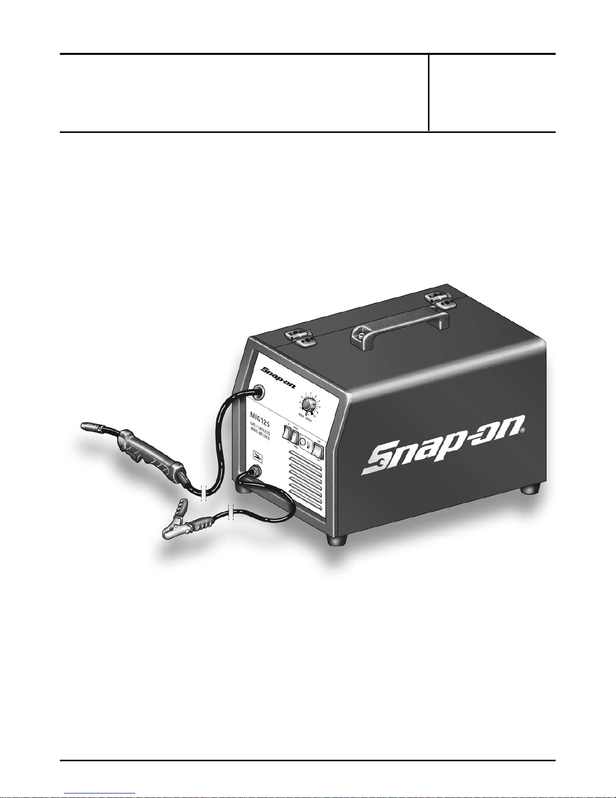
MIG125
IMPORTANT OPERATING INSTRUCTIONS
SAVE THESE INSTRUCTIONS
Page 2

2
DANGER
Electric welding or plasma cutting cause ultraviolet rays and weld spatter.
Bystanders will be exposed to ultraviolet rays and weld spatter.
Wear welding helmet with appropriate shade lens while using electric
welders or plasma cutters.
Do not allow bystanders while welding or cutting.
Wear safety shield and protective clothing (user and bystanders).
Read and follow instructions.
Ultraviolet rays will burn eyes; weld spatter can cause injury.
WARNING
Acetylene gas does not burn safely with torches.
Do not use torches with acetylene gas.
Read and follow instructions.
Uncontrolled burning can cause injury.
Materials can cause sparks or flying metal when heated which can cause
fire.
Wear safety shield and protective clothing (user and bystanders).
Sparks, fire and flying metal can cause injury.
WARNING
Electrical shock can result from absence of grounding prong.
Do not remove or bypass the grounding prong in any electrical plug.
Electrical shock can cause injury.
Smoke, fumes and gases are created by the welding process.
Use only in well ventilated area.
Avoid breathing smoke, fumes and gases.
Smoke, fumes and gases can cause injury.
i
i
i
Page 3
3
INSTRUCTION MANUAL FOR WIRE WELDING MACHINES
WARNING!
READ, UNDERSTAND AND FOLLOW THIS MAN-
UAL CAREFULLY BEFORE INSTALLING, USING,
OR SERVICING THE WELDING MACHINE, PAYING SPECIAL ATTENTION TO SAFETY RULES. CONTACT YOUR
DEALER IF YOU DO NOT FULLY UNDERSTAND THESE
INSTRUCTIONS.
1 INSTALLATION
This machine must be used for welding only. It must not
be used to defrost pipes.
It is also essential to pay special attention to the chapter
on SAFETY PRECAUTIONS.The symbols next to certain
paragraphs indicate points requiring extra attention,
practical advice or simple information.
This manual must be stored carefully in a place familiar to
everyone involved in using the machine. It must be consulted whenever doubts arise and be kept for the entire
life-span of the machine; it will also be used for ordering
replacement parts.
1.1 PLACEMENT
Unpack the machine and place it in an adequately ventilated area, dust-free if possible, taking care not to block
the air intake and outlet from the cooling slots.
CAUTION!
REDUCED AIR CIRCULATION causes overheat-
ing and could damage internal parts.
Keep at least 20 inches of free space around the machine.
Never place any filtering device over the air intake points
of this welding machine.
The warranty shall become void if any type of filtering
device is used.
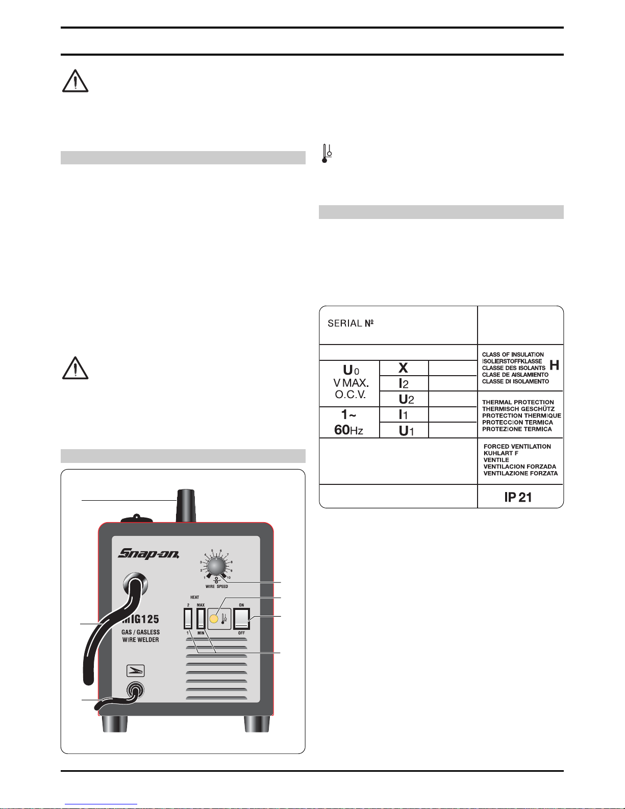
2 DESCRIPTION OF THE MACHINE
A) Switch
Turns the machine on and off.
B) Adjustment switches
By means of these switches one adjusts the welding
voltage.
C) Ground cable
D) Yellow LED
Lights only when the thermostat is tripped and inter-
rupts the machine operation.
F) Welding torch
G) Handle
Use this handle to lift the machine.
3 GENERAL DESCRIPTIONS
3.1 SPECIFICATIONS
This welder is used for welding soft steel, stainless steel
and aluminium.
3.2 EXPLANATION OF TECHNICAL SPECIFICATIONS
N° Serial number, which must always be indicated
in any inquiry regarding the welding machine.
U0 Secondary no-load voltage.
X The duty cycle expresses the percentage of
10 minutes during which the welding machine
can run at a certain current without overheating.
Example: X = 60% at I2 = 100 A
This means that the machine can weld with a
current I2 = 100A for 6 out of 10 minutes, thus
60%.
I2 Welding current
U
2 Secondary voltage with welding current I2
U
1 Rated power voltage.
1~60HzSingle-phase 60-Hz power supply.
I1 Current absorbed at the corresponding welding
current I2
IP21 Degree of housing protection.
Grade one as the second digit means that this
device is not suitable for use outdoors in the rain.
Fig. 1
C
F
G
D
B
E
A
Page 4
4
3.3 DESCRIPTION OF PROTECTION
This device is protected by a normally closed thermostat
on the power transformer.
When the thermostat is tripped the machine stops welding, while the motor-driven fan continues to run and the
yellow LED lights.
After it has been tripped, wait a few minutes to allow the
transformer to cool down.
4 INSTALLATION
WARNING!
The MIG125 must be installed by qualified person-
nel. All connections must be made in full compliance with all applicable rules and regulations.
Make sure that the wire diameter corresponds to the one
indicated on the roller, and mount the wire reel. Make sure
that the welding wire passes through the groove in the
small roller.
Before connecting the power cable 13, make sure that
the power voltage corresponds to that of the welder , then:
a) for permanent connection to the power mains
without a plug, you must insert a main switch having a
suitable capacity in compliance with the rated
specifications.
b) for a plug-socket connection, use a plug having a
suitable capacity in compliance with the rated
specifications. In this case the plug must be used to
completely disconnect the machine from the mains,
after setting the switch 33 to “O” (off).
The yellow-green wire must be connected to the ground
terminal. Connect the ground clamp 21 to the part to be
welded. The welding circuit must not be deliberately
placed in direct or indirect contact with the protection
wire except in the workpiece.
If the workpiece is deliberately grounded using the protection wire, the connection must be as direct as possible, using a wire at least as large as the welding current
return wire, and connected to the workpiece at the same
point as the return wire, using the return wire clamp or a
second grounding clamp placed next to it. All precautions
must be taken to avoid stray welding currents.
Turn the machine on using the switch 33.
Remove the tapered gas tip by turning it clockwise.
Unscrew the contact tip.
Do not press the torch trigger until you have read the
instructions carefully.
It is important to make sure the machine is turned off
whenever changing the wire reel and wire roller, to prevent the wire feed motor from starting accidentally.
Press the torch trigger and release it only when the welding wire comes out.
Welding wire can cause puncture wounds.
Never aim the torch at parts of the body, other people or
metals when loading the welding wire.
Screw the contact tip back on, making sure that the hole
diameter corresponds to the wire used.
Slide the tapered gas welding tip on, always turning
clockwise.
4.1 CONNECTING THE GAS HOSE
The gas cylinder must be equipped with a pressure reg-
ulator and gauge.
If the cylinder is placed on the cylinder holder of the
machine, it must be held in place by the chain provided
and be of an appropriate size to avoid jeopardizing the
stability of the machine.
Connect the gas hose leaving the back of the machine
to the pressure regulator only after the cylinder is in place.
Open the gas cylinder and set the gauge to approxi-
mately 20-25 CFH.
CAUTION: Make sure the gas used is compatible with the
material to be welded.
5 WELDING
5.1 WELDING MILD STEEL
5.1.1 With shielding gas.
Either 75% ARGON + 25% CO2 or 100% CO2 may be
used for welding mild steel.
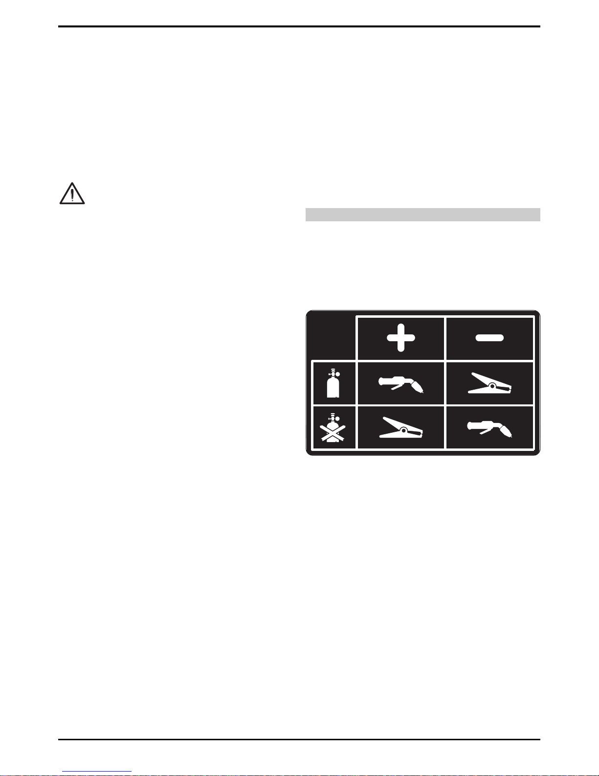
Connect the cables according to the instructionsgiven in
the plate stuck inside the machine (see figure 2).
Select the welding current by means of the switches 35.
Move the torch near the welding point and press the trigger.
Adjust the potentiometer knob 27 until the welding is
done with a constant, continuous noise.
If the speed is too fast, the wire tends to stick to the piece
and cause the torch to skip; if the speed is too low, the
wire melts in spaced drops or the arc does not remain lit.
When you have finished welding, turn off the machine and
close the gas cylinder.
For the correct welding angle see figure 3.
5.1.2 Without shielding gas.
Connect the cables according to the instructionsgiven in
the plate stuck inside the machine (see figure 2).
Use only diam. .035 flux cored wire that complies with
thestandard AWS AS.20 E71 TII or E71 TGS, suitable for
use without shielding gas.
Connect the ground cable clamp to the workpiece.
After connecting the cables, follow the instructions given
in paragraph 5.1.1.
NOTE: For compact, well-protected welds always work
from left to right and from top to bottom.
Remove all waste after each welding operation.
For the correct welding angle see figure 3.
Fig. 2
Page 5

5
5.2 WELDING ALUMINIUM
The welder must be prepared as for welding mild steel
with gas protection, but with the following differences:
- 100% ARGON as the shielding gas for welding.
- A wire having a composition suited to the base material
to be welded.
For welding ALLUMAN: 3÷5% silicon wire
- For welding ANTICORODAL: 3÷5% silicon wire
- For welding PERALUMAN: 5% magnesium wire
- For welding ERGAL: 5% magnesium wire
Use grinding wheels and brushes specifically designed
for aluminium, and never use them on other materials.
REMEMBER that cleanliness is quality!
The wire reels must be stored in nylon bags with dehumidifying packets.
For the correct welding angle see figure 3.
5.3 WELDING STAINLESS STEEL
The welder must be prepared as for welding mild steel
with gas protection, but with the following differences:
- Reel of stainless steel wire compatible with the composition of the material to be welded.
- Cylinder containing 98% ARGON + 2% 02 (recommended composition)
The recommended torch angle and welding direction are
shown in figure 3.
6 MAINTENANCE AND CHECKS
6.1 GENERAL NOTES
WARNING!
Turn off the welder and unplug the power cord from the
socket before each checking and maintenance operation.
Moving parts can cause serious injuries.
Keep away from moving parts.
GLOWING HOT SURFACES can cause serious
burns.
Let the unit cool before servicing.
Periodically remove any dust or foreign matter that may
have deposited on the transformer or diodes; to do so,
use a jet of clean, dry air.
When replacing the wire roller, make sure the groove is
aligned with the wire and corresponds to the diameter of
the wire used.
Always keep the interior of the gas nozzle clean to avoid
metal bridges created by welding dross between the gas
nozzle and the contact tip. Make sure the outlet hole of
the contact tip has not expanded excessively; if so,
replace.
Strictly avoid striking the torch or allowing it to suffer
violent impact.
6.2 TROUBLESHOOTING GUIDE
7 SAFETY PRECAUTIONS
7.1 FIRE
WARNING!
Avoid causing fire because of sparks, slag, hot
metal or pieces.
Make sure that suitable fire-fighting equipment
is available close to welding area.
Remove all flammable and combustible material from
the welding area and its surrounding (32 ft minimum).
Do not weld containers of combustible or flam
mable material, even when empty.
Fig. 3
TROUBLE
The welding machi-
ne supplies limited
current
Welding with a lot
of metal spatter
The wire jams or
entangles between
the drive rolls and
the torch infeed wire
guide
No wire feed or irregular wire feed
Porosity in the welding seam
PROBABLE CAUSE
Line fuse blown
Burnt out diode or diodes
Burnt out electronic board
Loose torch or ground
connections or any other
electrical power connections
Voltage adjustment switch
has a loose contact
Improper adjustment of
welding parameters
Poor ground connection
Contact tip with wrong diameter
Misalignment of the drive
roll groove
Obstructed or clogged
liner
Drive roll with too large a
groove
Obstructed or clogged
liner
Wire holding roller not
completely tightened
Clogged contact tip
Insufficient shielding gas
Excess oxidation of the
edges to be welded
Gas nozzle partially or
completely clogged by
spatter
REMEDY
Replace line fuse
Replace
Replace
Tighten all connections
Replace the switch
Select the correct parameters through the weldingvoltage switch and the
wire-speed adjustment
potentiometer
Check grounding connections
Replace
Realign
Remove and clean
Replace the drive roll
Remove and clean
Tighten all the way
Replace
Increase gas delivery
Thoroughly clean the
edges with a metal brush
Remove and clean or
replace being careful not
to clog the gas outlets
Page 6

6
Allow the welded material to cool down before
touching it or putting it in contact with combusti
ble or flammable material.
Do not weld parts with hollow spaces, containing flam-
mables.
Do not work under conditions with high concentrations
of combustible vapours, gases, or flammable dust.
Always check the work area half an hour after welding
so as to make sure that no fire has started.
Do not keep any combustible material such as lighters
or matches in your pockets.
7.2 BURNS
WARNING!
Wear protective clothing in order to protect
against burns caused by ultraviolet radiation
given off by the arc, and from weld metal sparks
and slag.
Wear protective gloves designed for use in wel
ding, hat and high safety-toe shoes. Button shirt
collar and pocket flaps, and wear cuff-less trou-
sers to avoid entry of sparks and slag.
Wear helmet with safety goggles and
glasses with side shields underneath,
appropriate filter lenses or plates (protected by clear cover glass). This is a MUST for welding to
protect the eyes from radiant energy and flying metal.
Replace cover glass when broken, pitted, or spattered.
Avoid oil or greasy clothing. A spark may ignite them.
Hot metal such as electrode stubs and workpieces
should never be handled without gloves.
Ear plugs should be worn when working on
overhead or in a confined space. A hard hat
should be worn when others work overhead.
Flammable hair preparations should not be used by
persons intending to weld or cut.
7.3 FUMES
WARNING!
Welding operations give off harmful fumes and
metal dusts which may be hazardous to your
health, therefore:
Work in a well-ventilated area.
Keep your head out of fumes.
In closed areas, use suitable exhaust fans.
If ventilation is not enough, use breathing
apparatus approved for this procedure.
Clean the material to be welded of any solvents or halo-
gen degreasers. Some clorine solvents may decompose
with the radiation emitted by the arc, and create phosgene gas.
Do not weld plated metals or those containing lead,
graphite, cadmium, zink, chrome, mercury or beryllium,
unless you have the proper breathing apparatus.
The electric arc creates ozone. A long exposure to high
concentrations may cause headaches, nasal, throat and
eye irritation as well as serious congestions and chest
pains.
IMPORTANT: DO NOT USE OXYGEN FOR VENTILATION.
Gas leaks in a confined space should be avoided.
Leaked gas in large quantities can change oxygen concentration dangerously. Do not bring gas cylinders into a
confined space.
DO NOT WELD where solvent vapors can be drawn into
the welding atmosphere or where the radiant energy can
penetrate to atmospheres containing even minute
amounts of trichloroethylene or perchloroethylene.
7.4 EXPLOSIONS
WARNING!
Do not weld above or near containers under
pressure.
Do not weld in environments containing
explosive dusts, gases or vapors.
This welding machine uses inert gases such as CO2,
ARGON, or a mixture of ARGON + CO2 for the protection
of the arc, thus you should take special precautions:
A) CYLINDERS
Do not directly connect cylinder to the machine gas
hose without a pressure regulator.
Handle or use pressure cylinders in conformity with the
existing rules.
Do not use leaking or damaged cylinders.
Do not use cylinders which are not well secured.
Do not carry cylinders without the protection of the
installed valve.
Do not use cylinders whose content has not been
clearly identified.
Never lubricate cylinder valves with oil or grease.
Do not put the cylinder in electrical contact with the arc.
Do not expose cylinders to excessive heat, sparks, mol-
ten slags or flame.
Do not tamper with the cylinder valves.
Do not try to loosen tight valves by means of hammers,
keys, or any other object.
NEVER DEFACE or alter name, number, or other
markings on a cylinder.
Do not lift cylinders off the ground by their valves or
caps, or by chains, slings or magnets.
Never try to mix any gases in a cylinder.
Never refill any cylinder.
Cylinder fittings should never be modified or exchan-
ged.
B) PRESSURE REGULATORS
Keep pressure regulators in good condition. Damaged
regulators may cause damages or accidents, they should
only be repaired by skilled personnel.
Do not use regulators for gases other than those for
which they are manufactured.
Never use a leaking or damaged regulator.
Never lubricate regulators with oil or grease.
C) HOSES
Replace hoses which appear damaged.
Keep the excess hose wound and out of the working
area in order to avoid any damage.
Page 7

7
7.5 RADIATIONS
WARNING!
Ultra-violet radiation created by the arc may
damage your eyes and burn your skin. Therefore:
Wear proper clothing and helmet.
Do not use contact lenses!!
The intense heat coming from the
arc may cause them to stick to the cornea.
Use masks with grade DIN 10 or DIN 11 safety lenses
at the least.
Protect people in the surrounding welding area.
Remember: the arc may dazzle or damage the eyes. It is
considered dangerous up to a distance of 15 meters (50
feet). Never look at the arc with the naked eye.
Prepare the welding area so as to reduce reflection and
transmission of ultra-violet radiation. Install sheathings or
curtains to reduce ultra-violet transmissions.
Replace mask lenses whenever damaged or broken.
7.6 ELECTRIC SHOCK
WARNING!
Electric shock can kill.
All electric shocks are potentially fatal.
Do not touch live parts.
Insulate yourself from the piece to be welded and from
the ground by wearing insulated gloves and clothing.
Keep garments (gloves, shoes, hats, clothing) and body
dry.
Do not work in humid or wet areas.
Avoid touching the piece to be welded.
Should you work close to or in a dangerous area, use all
possible precautions.
If you should feel even the slightest electric shock sen-
sation, stop welding immediately. Do not use the machine until the problem is identified and solved.
Have an emergency disconnect switch as close to the
machine as possible and make sure all personnel are
aware of the switch’s location.
Frequently inspect the power supply cable.
Disconnect power supply cable from mains before
replacing cables or before removing unit covers.
Do not use the unit without installed covers.
Always replace any damaged parts of the unit, with ori-
ginal material.
Never disconnect unit safety devices.
Make sure that the power supply line is equipped with
a properly grounded plug.
Make sure that the work bench is connected to a good
earth ground.
Any maintenance should only be carried out by qualified
personnel.
7.7 PACE MAKER
WARNING!
Magnetic fields from high currents can affect pace-
maker operation. Persons wearing electronic life support
equipment (pacemaker) should consult their doctor before going near any welding operations.
7.8 WELDING WIRE CAN CAUSE PUNCTURE
WOUNDS.
WARNING!
Do not press gun trigger until instructed to do so.
Do not point gun toward any part of the body, other
people, or any metal when threading welding wire.
7.9. MOVING PARTS CAN CAUSE INJURY.
WARNING!
Moving parts, such as fans, can cut fingers and
hands and catch loose clothing.
Keep all doors, panels, covers, and guards clo-
sed and securely in place.
Have only qualified people remove guards or covers for
maintenance and troubleshooting as necessary.
Keep hands, hair, loose clothing, and tools away from
moving parts.
Reinstall panels or guards and close doors when servi-
cing is finished and before starting the machine.
7.10 NOISE
WARNING!
The welding procedure may produce noise levels
in excess of 80 dB. in which case the machine
operator must take the necessary safety precau-
tions as prescribed by the national safety regulation.
Page 8

8
Part #
Ref. Model Description
# MIG125
1 CKS246948 CLOSING
2 5801616 PANEL SIDE
3 3165110 WIRE FEED MOTOR
4 CKS248427 COIL SUPPORT COMPLETE
4 CKS251030 RING
4 CKS251031 SPRING
4 CKS251027 COIL SUPPORT SPACER
4 CKS251022 COIL SUPPORT
5 CKS251067 TERMINAL BOARD
6 5802830 CENTER DEVIDER
7 3120065 HINGE
8 3055203 HANDLE
9 5801615 FIXED SIDE PANEL
10 CKS260513 SOLENOID VALVE
11 CKS260453 FAN MOTOR
12 CKSB7022370 CABLE HOLDER
13 CKSB7023370 MAIN INPUT CABLE
14 CKSB7015370 RECTIFIER
15 5610061 TRANSFORMER
16 3115078 FOOT
17 CKSB7065370 THERMOSTAT
18 CKSB7028370 THERMOSTAT SUPPORT
21 CKS246983 EARTH CABLE
24 3070081 FRAME
27 CKSB7128370 KNOB
29 CKSB7067370 CIRCUIT BOARD
31 8124700 TORCH
32 5801818 UNDERCARRIAGE
33 CKSB7069370 SWITCH
34 CKS246251 LAMP HOLDER
35 CKSB7070370 SWITCH
36 CKSB7050370 CONTACTOR
37 CKS260568 SUPPORT
38 5803525 SUPPORT
39 MIG1153 STEEL LINER
40 3190066 SWITCH
41 3055629 HANDLE COMPLETE
42 8186000 TORCH NECK
43 CKSB7124370 SPRING
44 MIG1156 DIFFUSER
45 MIG023 .023” (.6MM) CONTACT TIP
45 MIG030 .030” (.8MM) CONTACT TIP
45 MIG035 .035” (.9MM) CONTACT TIP
46 MIG1151 TAPERED NOZZLE
46 MIG1152 SPOT NOZZLE
ALL CONSUMABLES AND REPAIR PARTS
SHOULD BE ORDERED THROUGH YOUR
SNAP-ON DEALER.
Page 9

9
MODEL MIG125
Page 10

10
Page 11

11
Page 12

12
 Loading...