

Page 1

User Manual
June 2010
EAZ0067L10A Rev. A
Page 2

Trademarks
IMPORTANT:
Blue Point, MICROSCAN, Scanner, Snap-on, and ShopStre am Conne ct are trademar ks of Snap- on Inco rpor ated,
registered in the United States and other countries.
All other marks are trademarks or registered tr ademarks of th eir resp ective hold ers.
Copyright Information
©2010 Snap-on Incorporated. All rights rese rved.
Disclaimer of Warranties and Limitation of Liabilities
The information, specifications and illustrations in this manual are based on the latest information available at the
time of printing. While the authors have taken due care in the p rep ara tion of this manua l, nothing con t ained he rein:
• Modifies or alters in any way the standard terms and cond itions of the purchase, lea se, or rent al agre ement
under the terms of which the equipment to which this m anual relate s was acquired.
• Increases in any way the liability to the customer or to third parties.
Snap-on reserves the right to make changes at any time without notice.
Before operating or maintaining this u nit, please read this ma nual carefully paying extra attention to the safety
warnings and precautions.
Visit our websites at:
www.diagnostics.snapon.com/microscan (North America)
snapondiag.com (United Kingdom)
sun-diagnostics.com (United Kingdom)
For Technical Assistance Call
1-800-424-7226 (North America)
CALL +44 (0) 845 601 4736 (United Kingdom)
E-mail DiagnosticsUKproductsupport@snapon.com (United King dom)
For technical assistance in all other markets, cont act your selling agent.
ii
Page 3

Safety Information
!
DANGER
!
WARNING
!
CAUTION
For your own safety and the safety of others, and to prevent damage to the equipment an d
vehicles upon which it is used, it is important that these Safety Messages be read and understood
by all persons operating, or coming into contact with, the equip ment.
This product is intended for use by properly trained and ski lled pro fessional automo tive
technicians. The safety messages presented throughout this manual are reminders to the
operator to exercise extreme care when using this test instrument.
There are many variations in procedures, techniques, tools, and p art s for servicing vehicles, as
well as in the skill of the individual doing the work. Because of the vast number of test applications
and variations in the products that can be tested with this instrument, we cannot possibly
anticipate or provide advice or safety messages to cover every situation. It is the automotive
technician’s responsibility to be knowledgeable of the system being tested. It is essential to use
proper service methods and test procedures. It is import ant to perform tests in an appropriate and
acceptable manner that does not endanger your sa fety, the safety of others in the work area, the
equipment being used, or the vehicle being tested.
It is assumed that the operator has a thorough underst anding of vehicle systems before using this
product. Understanding of these system principl es and oper ating theor ies is nece ssary for
competent, safe and accurate use of this instrument.
Before using the equipment, always refer to and follow the safety messages and app licable te st
procedures provided by the manufacturer of the vehicle or equipment being tested. Use the
equipment only as described in this manual.
Read, understand and follow all safety messag es and instructio ns in this manual, the
accompanying safety manual, and on the test equi pment.
Safety Message Conventions
Safety messages are provided to help prevent personal injury and equipm ent damage. All safety
messages are introduced by a signal word indicating the haza rd level.
Indicates an imminently hazardous situation which, if not avoided, will result in death or serious
injury to the operator or to bystanders.
Indicates a potentially hazardous situation which, if n ot avoided, could result in death o r serious
injury to the operator or to bystanders.
Indicates a potentially hazardous situation which, if not a voided, may r esult in modera te or mino r
injury to the operator or to bystanders.
iii
Page 4

Safety Information Important Safety Instructio ns
!
WARNING
Safety messages contain three different type styles.
• Normal type states the hazard.
• Bold type states how to avoid the hazard.
• Italic type states the possible consequences of not avoid ing th e hazard.
An icon, when present, gives a graphical description of the potential hazard.
Example:
Risk of unexpected vehicle movement.
• Block drive wheels before performing a test with engine running.
A moving vehicle can cause injury.
Important Safety Instructions
For a complete list of safety mess ages, refer to the accomp anying safety manual.
SAVE THESE INSTRUCTIONS
iv
Page 5

Contents
Safety Information..................................................................................................................... iii
Contents...................................................................................................................................... v
Chapter 1: Using This Manual................................................................................................... 1
Conventions.................................................................................................................................. 1
Bold Text................................................................................................................................ 1
Terminology ........................................................................................................................... 1
Notes and Important Messages............................................................................................. 1
Procedures............................................................................................................................. 2
Additional Manuals........... ... .... ... ....................................... ... ... ... ... .... ... ........................................ 2
Chapter 2: Introduction.............................................................................................................. 3
Functional Description...................................... .... ... ... ... .... ... ...................................... .... ... ........... 3
Technical Specifications............................................................................................................... 5
Control Buttons............................................................................................................................. 6
Y (Accept) Button................................................................................................................... 6
N (Back) Button...................................................................................................................... 6
Power Button ......................................................................................................................... 6
Up Button............................................................................................................................... 6
Down Button .......................................................................................................................... 6
Connections.................................................................................................................................. 7
USB Port....................... .... ... ... ... ....................................... ... ... .... ... ... ... .................................. 7
Data Cable Connector ........................................................................................................... 7
Power Supply ............................................................................................................................... 7
Vehicle Power........................................................................................................................ 7
USB Power ... ... .... ... ... ....................................... ... ... .... ... ... ... ....................................... ... ........ 7
Battery Power ........................................................................................................................ 7
Data Cable.................................................................................................................................... 7
Chapter 3: Getting Started......................................................................................................... 8
Supplying Power.................. .... ...................................... .... ... ... ... ... ............................................... 8
Installing the Battery..................................................................................................................... 8
Connecting to Vehicle Power ....................................................................................................... 9
Powering On the Unit ................................................................................................................... 9
Selecting a Language................................................................................................................... 9
Chapter 4: On-Board Diagnostics (OBD) ............................................................................... 10
Global OBD and What it Means ................................................................................................. 10
OBD-II Start-up Phase......................................................................................................... 10
EOBD Start-up Phase.......................................................................................................... 11
OBD-II/EOBD Limitations ..................................... ... ... ... .... ... ... ... ....................................... ... ...... 11
OBD-II/EOBD Advantages ............ ....................................... ... ... ... .... ... ... ................................... 11
Communication Protocols........................................................................................................... 11
What is CAN? ...................................................................................................................... 12
v
Page 6

Contents
Diagnostic Services Introduction...... ... .... ... ... ... .... ...................................... .... ... ... ... ... .... ............12
Readiness Monitor Test Status............................................................................................ 12
MIL Status............................................................................................................................ 14
Diagnostic Service Definitions.............................. ... ....................................... ... ... ... ... .... ... ......... 15
Service $01: Display Current Data....................................................................................... 15
Service $02: Powertrain Freeze Frame Data....................................................................... 15
Service $03: Emission-related DTCs................................................................................... 16
Service $04: Clear/Reset Emission-related Diagnostic Data............................................... 17
Service $05: Oxygen Sensor Monitoring Test Results......................................................... 18
Service $06: Specific Monitored Systems Test Results....................................................... 22
Service $07: Emission-related DTCs detected during Current or
Last Completed Drive Cycle (Pending Codes)..................................................................... 23
Service $08: On-board Activation Tests............................................................................... 24
Service $09: Vehicle Information ...................... ... ... .... ... ... ....................................... ... ... ... ... 24
Service $09: In-use Performance Tracking.......................................................................... 24
Chapter 5: Navigation .............................................................................................................. 26
Screen Layout ............................................................................................................................ 26
Trouble Code Screens................................................................................................................ 26
Menu Screens ......................... ... ... ... ... ....................................... ... .... ... ... ... .... ............................ 27
Main Menu ........................................................................................................................... 28
Global OBD-2/EOBD Menu............................ ... ... ... ....................................... ... ... .... ... ... ... ... 28
Exit Menu............................................................................................................................. 29
Data Screens.............................................................................................................................. 30
Text View ............................................................................................................................. 30
Graph View ..........................................................................................................................31
Screen Messages....................................................................................................................... 33
Loading and Connecting Messages..................................................................................... 33
Confirmation Messages ....................................................................................................... 33
Warning Messages .............................................................................................................. 33
Error Messages.................................................................................................................... 33
Chapter 6: Operations.............................................................................................................. 34
Global OBD-2/EOBD.................................. ... ....................................... ... ... .... ... ... ... ................... 34
Readiness Status................................................................................................................. 34
Current Data . ... .... ... ... ... ....................................... ... .... ... ... ... ... ....................................... ...... 35
Freeze Frame Data........... ... ....................................... ... ... ... ... .... ... ...................................... 35
Confirmed Codes.................................................................................................................36
Clear Codes......................................................................................................................... 36
O2 Monitors ......................................................................................................................... 37
Non-Cont. Monitors..............................................................................................................37
Pending Codes .................................................................................................................... 38
Request Control of On-board System............ ... ... ... .... ... ... ...... .... ... ... ... .... ... ... ... ... .... ... ... ... ... 38
Vehicle Information ..............................................................................................................38
Movie.......................................................................................................................................... 39
Settings....................................................................................................................................... 39
Global OBD-2/EOBD Help................ ... .... ... ....................................... ... ... ... .... ... ... ......................40
Select Protocol ........................................................................................................................... 40
vi
Page 7

Contents
Chapter 7: Data Parameters .................................................................................................... 42
Long Parameter Names .......................... ... ... ... .... ...................................... .... ... ... ... ... .... ............ 42
Short Parameter Names ...................................................................................................... 46
DTC Association .................................................................................................................. 50
Chapter 8: Maintenance........................................................................................................... 54
Cleaning and Damage Inspection .............................................................................................. 54
Replacing the Battery....... ... .... ... ....................................... ... ... ... ... .... ... ...................................... 54
Storage Tips........... .... ... ... ....................................... ... ... .... ... ... ... ................................................ 55
Appendix A: Troubleshooting................................................................................................. 56
Communication Problems ..........................................................................................................56
Erratic or No Communication............................................................................................... 56
Testing the Data Link Connector ......................................................................................... 56
Check the Malfunction Indicator Lamp................................................................................. 58
Appendix B: Downloading and Installing Software Updates ............................................... 59
Check for Service Updates Before Use...................................................................................... 59
Verifying Minimum PC Requirements......................................................................................... 59
Verifying PC System Properties........................................................................................... 60
Downloading and Installing ShopStream Connect..................................................................... 60
Downloading Service Updates ................................................................................................... 62
Before You Begin................................................................................................................. 63
Installing a Service Update .................................................................................................. 63
Appendix C: Software License Agreement............................................................................ 66
Appendix D: Product Warranty............... ... ... .... ... ... ... ....... ... ... ... .... ... ... ... .... ... ... ... ... .... ... ... ... ... 69
Index.......................................................................................................................................... 70
vii
Page 8

Chapter 1 Using This Manual
This manual contains tool usage instructions.
Some of the illustrations shown in this manual may contain modules and optional equipment that
are not included on your system. Contact your sales representative for availability of other
modules and optional equipment.
1.1 Conventions
The following conventions are used.
1.1.1 Bold Text
Bold is used in procedures to highlight selectable items such as bu ttons and menu o ptions.
Example:
• Press the Y button.
1.1.2 Terminology
The term “select” means highlighting a button or menu item u sing the arrow buttons an d pressing
the Y button to confirm the selection.
Example:
• Select Clear Codes.
The above statement abbreviates the following procedu re:
1. Scroll with the arrow buttons to highlight Clear Codes on the menu.
2. Press the Y button.
1.1.3 Notes and Important Messages
The following messages are used.
Notes
A NOTE provides helpful information such as additional explanations, tips, and comment s.
Example:
1
Page 9

Using This Manual Additional Manuals
NOTE:
IMPORTANT:
i For additional information refer to...
Important
IMPORTANT indicates a situation which, if not avoided, may result in damage to the test
equipment or vehicle.
Example:
The Test ID Table below is for CAN Protocol only.
1.1.4 Procedures
An arrow icon indicates a procedure.
Example:
z To change screen views:
1. Scroll to highlight Settings on the main menu and press Y to select.
A sub-menu of language options displays.
2. Highlight the desired language and press Y to select.
1.2 Additional Manuals
This tool works in conjunction with other software products. All of the required manuals are
included on the Diagnostics website. See the appropriate manu al for information regarding these
products.
2
Page 10
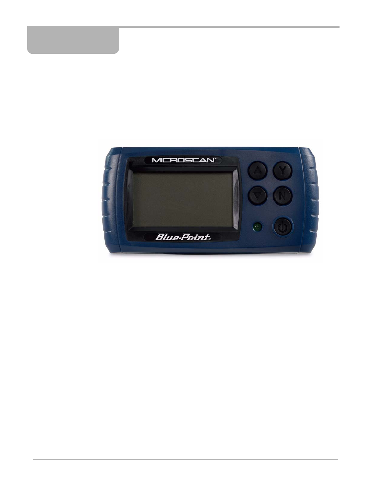
Chapter 2 Introduction
Y our new MICROSCAN™ scan tool provides European On-board Diagnostic (EOBD) trouble
codes and datastream information for electronic vehicle control systems. Your MICROSCAN
can also graph live data parameters, recor d data, clear diagnostic trouble codes (DTCs) from
the electronic control module (ECM), and reset the vehicle malfunction indicator lamp (MIL).
Contact your sales representative for availability of accessories and upgrades.
Figure 2-1
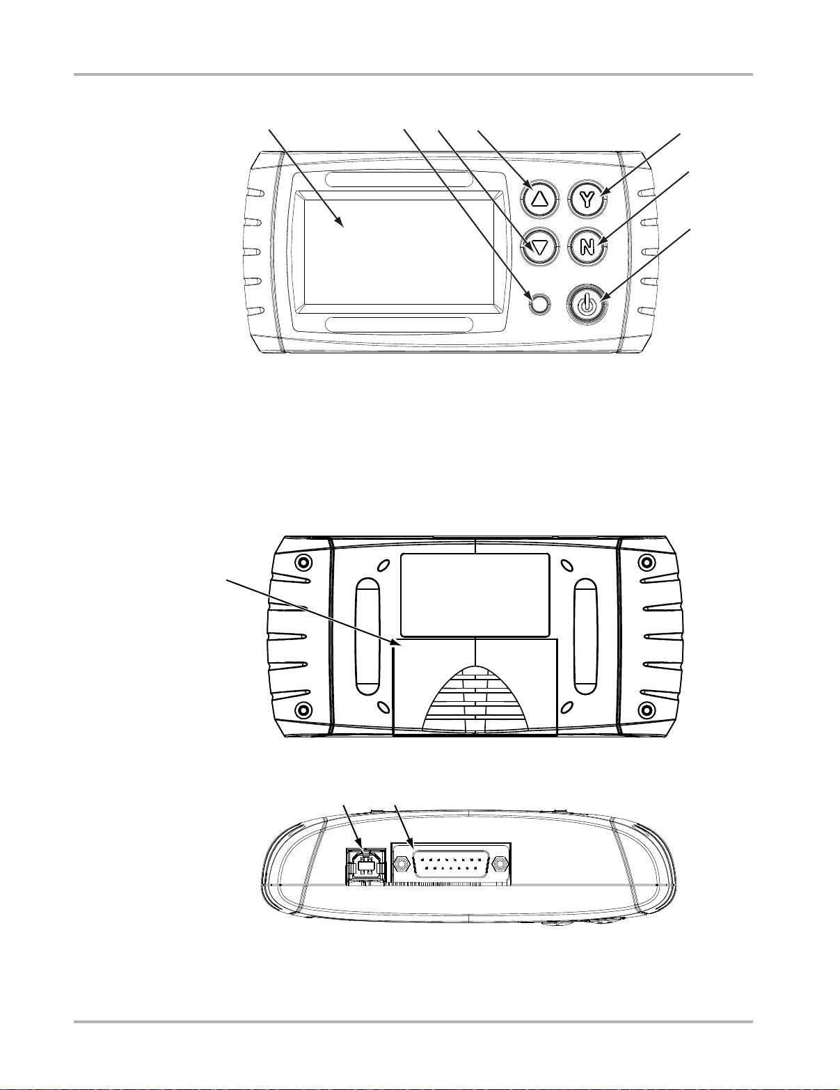
2.1 Functional Description
This section illustrates external features, ports and connectors of the OBD unit.
MICROSCAN
3
Page 11
IntroductionFunctional Description
1234
5
6
7
1
2
1— Liquid Crystal Display (LCD) Screen
2— Power Light emitting Diode (LED)
3— Down or Right Button
4— Up or Left Button
5— Y (Yes) Button
6— N (No) Button
7— Power Button
Figure 2-2
Front view
1
1— Battery Cover
1— USB Port
2— Data Cable Connector
Figure 2-3
Figure 2-4
Back view
T op view
4
Page 12

IntroductionTechnical Specifications
2.2 T echnical S pecifications
Display:
Liquid Crystal display (LCD) backlight monochrome screen
2.83 inch (72 mm) diagonal
Battery:
9-volt
Dimensions:
Width:
5.53 inch
140.4 mm
Height:
2.68 inch
68 mm
Depth:
1.57 inch
40 mm
Weight:
Without battery:
6.4 ounce
199 g
Operating Temperature Range:
14 to 140°F
–10 to 40°C
Storage Temperature Range:
–4 to 149°F
–20 to 65°C
Data Buffer:
64 data frames (values per parameter)
Communication Protocols:
Your MICROSCAN supports the following OBD-II/EOBD communications protocols:
• SAE J1850 (VPW and PWM)
• ISO 9141-2
• ISO 14230-2 (KWP 2000)
• ISO 15765-4 (CAN)
5
Page 13

IntroductionControl Buttons
2.3 Control Buttons
The MICROSCAN has the following control buttons; N (back), Y (accept), b (Up), d (Down),
and Power (Figure 2-2).
2.3.1 Y (Accept) Button
The Y button is used to do the following:
• To select the item that you highlighted using the direction buttons.
• To answer “Yes” when a Yes or No choice is given.
2.3.2 N (Back) Button
The N button is used to do the following:
• To open the Exit Menu
• To exit a menu or program.
• To close an open list and return to the previous menu.
• To answer “No” when a Yes or No choice is given.
• To return to the main menu.
2.3.3 Power Button
The Power button powers up the tool, and turns it off.
2.3.4 Up Button
The Up button is used to do the followin g:
• Move the highlight or cursor up when the screen arr ows are vertically aligned.
• Move the highlight or cursor right when the screen arrows ar e horizontally aligned.
2.3.5 Down Button
The Down button is used to do the following:
• Move the highlight or cursor down when the screen arrows are ver tically aligned.
• Move the highlight or cursor left when the screen ar rows are h orizo nt ally aligne d.
6
Page 14

IntroductionConnections
2.4 Connections
The MICROSCAN scan tool uses two connections; a USB port and a data cab le port
(Figure 2-4 on page 4):
2.4.1 USB Port
The USB port is for connecting to a personal computer (PC) and is used for up dating the
internal software, and for transferring saved files. The scan tool also re ceives power through
the USB port when it is connected to a PC.
2.4.2 Data Cable Connector
The data cable connector is used to connect the MICROSCAN scan tool to a vehicle data link
connector (DLC) for testing.
2.5 Power Supply
The MICROSCAN scan tool can receive power from th e test vehicle or through the USB port
when connected to a personal computer.
2.5.1 V ehicle Power
Vehicle power is required for the scan to ol to proper ly communica te with th e vehicle during
testing. The Data Cable provides power to th e unit throu gh the vehicle dat a link conn ector
(DLC). The scan tool turns on automatically and checks for stored codes whenever it is
connected to a DLC that provides power.
2.5.2 USB Power
The MICROSCAN scan tool can be powered by a personal computer (PC) when connected
to the PC with a standard USB cable.
2.5.3 Battery Power
The MICROSCAN scan tool can receive power from the internal 9V battery. Use battery
power to review saved files only.
2.6 Data Cable
A Data Cable is included with your MICROSCAN scan tool. The data cable plugs directly into
the 16-pin data link connector (DLC) on OBD-II vehicles.
7
Page 15
Chapter 3 Getting Started
To get started using your new MICROSCAN™ supply power to the tool.
3.1 Supplying Power
There are three ways to supply power to this scan tool:
• Install the battery
• Connect to vehicle power
• Connect to a personal computer (PC) with a USB cable
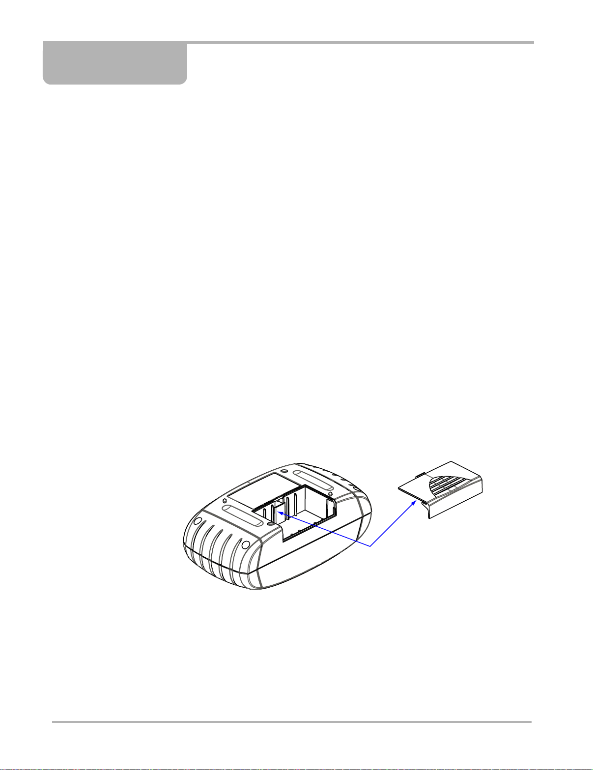
3.2 Installing the Battery
The MICROSCAN scan tool comes with a 9V battery that inst alls into a compartment on the
back side of the unit. When replacing the battery , use a heavy-duty typ e battery from a reliable
manufacturer . Ligh t-duty in expensive batter ies may not pr ovide suf ficient po wer to opera te
the scan tool, and may leak and damage your MICROSCAN.
z To install the battery:
1. Slide the battery cover on the back of the MICROSCAN unit down to release the lock tabs.
2. Pivot the cover up slightly and lift it off of the unit (Figure 3-1).
Figure 3-1
3. Connect a new 9-volt battery to the connector and fit the battery into th e comp artmen t.
4. Fit the center tab on the battery cover into the slot on the tool housing, pivot the cover
down, and slide it into position so that it locks into place on the housing.
Note the following safety warnings when installing batteries.
Battery cover removal
8
Page 16

Getting Started Connecting to Vehicle Power
!
WARNING
Risk of personal injury or harm.
• Always make sure the battery polarities (“+” and “–”) are correct when installing.
• Do not expose batteries to excessive heat.
• Use batteries from a reputable manufacturer only.
• Do not try to recharge batteries that are not specifically designed to be recharged.
• Do not allow children to install batteries unsupervised.
• Follow the battery manufacturer's instructions as to proper handling, storage, and
disposal of batteries.
Improper use of batteries can result in personal harm.
3.3 Connecting to V ehicle Power
The Data Cable, included with your MICROSCAN unit, plugs directly into the data link
connector (DLC) on OBD-II/EOBD vehicles.
z To connect to vehicle power:
1. Attach the 15-pin connector of the Data Cable to the MICROSCAN unit. Tighten the
captive screws to ensure a good connection.
2. Connect the 16-pin connector of the Data Cable to the DLC of the test vehicle.
3. Switch the vehicle ignition on.
4. The MICROSCAN unit automatically powers on and checks for diagnostic trouble codes
(DTCs) stored in the electronic control module (ECM) of the vehicle.
3.4 Powering On the Unit
When vehicle power is not available, you can manually power on your MICROSCAN unit
using the internal 9-volt battery. To manually power the tool, Press the Power button on the
front of the unit. Press the Power button on the front of the unit.
3.5 Selecting a Language
English is the default language selection in the scan tool software. Howe ver , you can ch ange
the language setting if desired.
z To change the language setting:
1. Select Settings from the main menu.
2. Select Languages from the settings menu.
3. Scroll to highlight the desired language and press Y.
4. Press N to exit.
The language remains as selected after powering down.
9
Page 17

Chapter 4 On-Board Diagnostics (OBD)
Y our new MICROSCAN conforms to Global OBD (OBD-II in North America and EOBD in Europe)
standards, and is designed for testing compliant vehicles. This chapter describes Global OBD.
4.1 Global OBD and What it Means
Many countries have enacted strict emission related regulations that will drive increased
technology into the modern automobile in order to reduce the exhaust emissions. Eur opean and
North American countries lead the way by adopting technology that st and ardizes the way these
vehicles can be checked for compliance.
The OBD-I (On-Board Diagnostics I) system was introduced in the ear ly 1980s an d by 1988 all
new cars and light trucks sold in California had to have OBD-I. The fund ament al e lement s of the
OBD-I are the electrical components (which influe nce exhaust emissions) that are mo nitored by
the engine management system. An optical warning signal is given in the event of an OBD-I
relevant failure. This fault can be read out by way of a flashing code.
OBD-II has been compulsory on all vehicles in the US market since January 1 996. EOBD
(European On-Board Diagnostics) is the European e quivalent to OBD-II. It was introduced in 2000
and became effective in January 2001. There a re a few differences between EOBD and OBD-II
but none that will affect scan tool operation. All the communication protocols for both programs are
identical. Vehicle emission strategies an d certification procedures vary betwe en countries, states
and regions. Always use service information specific to the country and emission certification.
EURO-3, also known as EOBD, is a continuation of the emission regulations known as EURO-1
and EURO-2. In addition to introducing stricter emission limits, the directive now also covers the
monitoring of emission related components and fun ctions during opera tion.
The OBD-II and EOBD system must show the failure of an emission related component or system
to the driver using a MIL (Malfunction Indicator).
What does OBD-II and EOBD mean for the Rep air Shop?
A universal connector can now be used on any OBD-II 1996 and newer an d EOBD 2001 and
newer vehicle, giving the shop more diagnostic cove rage th at was not pr eviously possib le.
4.1.1 OBD-II St art-up Phase
About 40% of the vehicles of model year 1995 sold in the USA were OBD-II prepared. Beginning
in 1996, all vehicles sold in the USA were supposed to comply with OBD-II standards.
However, some 1996 and 1 997 ve hicles were not fu lly OBD-II complian t. This mea ns that so me
early OBD-II vehicles may:
• Not have the standardized diagnostic connector location o r
• Have missing or only partially implemented OBD-II monitors.
10
Page 18

On-Board Diagnostics (OBD) OBD-II/EOBD Limitations
4.1.2 EOBD St art-up Phase
The European vehicle manufacturers also needed time to phase in and develop EOBD tests and
software in their electronic control modules (ECMs). Some of th e manufacturer s alre ady had
experience with the USA OBD-II. Others may still have to improve their most recent software
versions. This means that EOBD is experiencing similar phase in problems as OBD-II, with some
2001 and 2002 vehicles having limited EOBD functionality.
4.2 OBD-II/EOBD Limitations
Generic OBD-II/EOBD data is currently limited to:
• Emission diagnostics or
• Problems related to the Malfunction Indicator.
Access to all available data in the ECM (other systems, other parameters, enhanced diagnostics)
will still require a scan tool with manufacturer specific capabilities.
4.3 OBD-II/EOBD Advantages
The advantage of OBD-II and EOBD is the simple “Plug and Play” function:
• Unlike using a manufacturer specific scan tool or vehicle communication sof tware , one does
not have to select the vehicle make, year or model.
• The communication protocol can be automatically dete cted by the scan tool software.
• Depending on the ECM and amount of parameters selected, dat a update rates may vary. By
using functions as Custom Data List and Manual Select PID in Service $01, sometimes data
update rates may be higher than with manu factu rer specific so f tware. This can be help ful in
finding intermittent signal gulches.
Data and monitors that are not described in the OBD/EOBD st anda rds are filtered out, altho ugh
they are selectable.
4.4 Communication Protocols
A communication protocol is a standardized way of dat a commun ication b etween an ECM a nd a
scan tool.
For vehicles that comply with OBD-II and EOBD, the following communi catio n protocol s are
permitted:
• ISO 9141-2 (K-LINE)
• SAE J1850 PWM (Pulse Width Modulation) and VPW (Variable Pulse Width)
• ISO 14230-2 (Keyword Protocol 2000)
• ISO 15765-4 (CAN)
The scan tool can be setup so it will automatically determine the communication protocol used in
the vehicle under test.
11
Page 19

On-Board Diagnostics (OBD) Diagnostic Services Introduction
4.4.1 What is CAN?
CAN stands for Controller Area Network and means tha t control units are part of a network and
can interchange data. Although some car manufacturer s have used CAN for some year s for
communication between electronic control modules (E CMs), it was not d irectly conn ected to the
diagnostic connector . In approximately 2001/2002 for Europe and 2003 for No rth America, the first
car manufacturers started to connect the CAN communication lines to the dia gnostic connecto r.
CAN will be the only required protocol in near future for OBD.
4.5 Diagnostic Services Introduction
The OBD program is divided into several sub programs, called ‘Service $xx’. This complies to the
EOBD/OBD-II standards:
Table 4-1
1. Manual selection of Test IDs is not supported.
Diagnostic services
Service Description
System readiness test status display
$01
$02 Request powertrain freeze frame data
$03
$04 Clear/reset emission-related diagnostic data
$05 Oxygen sensor monitoring test results
$06
$07
$08 Onboard system activation tests
$09 Request vehicle information
$09 In-use Performance Tracking
MIL (malfunction indicator) Status & Control
Request current powertrain diagnostic data
Request emission-related DTCs (Diagnostic Trouble
Codes)
Request on-board monitoring test results for specific
monitored systems
Request Pending Codes (emission related
diagnostic trouble codes) detected during current or
last completed driving cycle
1
4.5.1 Readiness Monitor Test Status
OBD-II/EOBD stipulates the monitoring (continuous or non-continuous) of the functions of the
following emission control related subsystems):
Table 4-2 Continuous or Non-continuous monitors
Readiness Monitor Remark
Misfire monitoring Continuous
Fuel system monitoring Continuous
Comprehensive component monitoring Continuous
† Will only be monitored if the correct conditions are met.
12
Page 20
On-Board Diagnostics (OBD) Diagnostic Services Introduction
NOTE:
Table 4-2 Continuous or Non-continuous monitors
Readiness Monitor Remark
Catalyst monitoring †
Heated catalyst monitoring †
Evaporative system monitoring †
Secondary air system monitoring †
A/C system refrigerant monitoring †
Oxygen sensor monitoring †
Oxygen sensor heater monitoring †
EGR system monitoring †
† Will only be monitored if the correct conditions are met.
i Not all data is applicable or supported by all vehicles.
Each vehicle manufacturer has unique m onitor te st criteria. The Readine ss Test Status indicates
whether a particular diagnostic monitor or function pa ssed it s sp ecific test criteria an d was found
to be within specification.
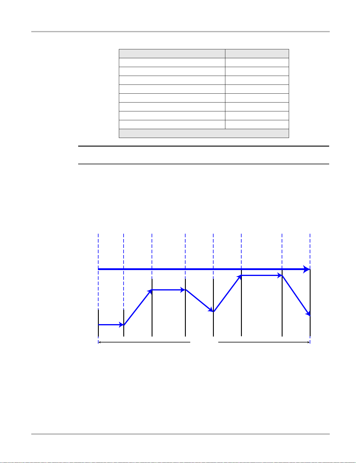
Usually the monitors should run and set the Readiness Test Status during normal vehicle
operation. The OBD-II Drive Cycle (see Figure 4-1: ‘Typical OBD-II Drive Cycle’) can be used to
drive the vehicle in a prescribed manner.
HO2 Heater, Misfire,
AIR, Fuel Trim, and
Purge Monitors
Idle 2.5 Minutes
in Drive, A/C &
Rear Defrost ON
Cold Start
ECT < 50C
Misfire, Fuel Trim, and
Purge Monitors
Accelerate at 50%
Throttle to 55 mph/
89 kph A/C OFF
Misfire, EGR, AIR, Fuel Trim,
HO2, and Purge Monitors
3 Minutes
Steady State Cruise
55 mph/89 kph
Figure 4-1
EGR, Fuel Trim, and
Purge Monitors
Decelerate to
20 mph/32 kph
with the Clutch
Engaged and
No Brakes
Total Time 12 Minutes
Misfire, Fuel Trim, and
Purge Monitors
Accelerate at
75% Throttle to
55 to 60 mph/
89 to 97 kph
Typi cal OB D- II Dr ive Cycl e
Catalyst, Misfire, EGR, Fuel
Trim, HO2, and Purge Monitors
5 Minutes
Steady State Cruise
55 to 60 mph/
89 to 97 kph
EGR, and Purge Monitors
Decelerate to
End of Cycle
Without Brakes
As this is a generic drive cycle, it may have limited results o n some vehicles. If available, use the
drive cycle information as supplied by the vehicle manufacturer.
System malfunctions that occur later and record a DTC (Diagnostic Trouble Code) will not change
the Readiness T est S t atus. When the failure is repaired and the DTC is era sed, all Readiness T est
Status will be reset to a ‘Not Completed’ st atus.
13
Page 21

On-Board Diagnostics (OBD) Diagnostic Services Introduction
NOTE:
NOTE:
Repair validation
Use the following procedure to validate a repair.
z To validate the repair:
1. Perform a drive cycle (generic or vehicle specific).
2. Check Service $07 (refer to 4.6.7: ‘Service $07: Emission-related DTCs detected during
Current or Last Completed Drive Cycle (Pending Codes)’ on page 23) and Service $03 (refer
to 4.6.3: ‘Service $03: Emission-related DTCs’ on page 16).
If no DTCs are reported (that relate to the initial failure), it can be assumed that the fault has been
repaired correctly.
4.5.2 MIL St atus
Emission related malfunctions set failure specific DTC(s). The MIL (Malfunction Indicator Lamp)
may light up as soon as the first emission related DTC has been stor ed and confirme d (stored a
second time). Depending on the type of malfunction, it may take multiple drive cycles before the
MIL turns on.
The MIL is located in the instrument p anel. The MIL may display a symbol of an engine and sho uld
light up as soon as the ignition is switched on . Three different st ates are possible when the engine
is running:
1. OFF: no emission limits exceeded.
2. ON: at least one OBD-II/EOBD emission limit exceeded.
3. Blinking: possibility of damage to the catalytic converter.
Figure 4-2
Example of Malfunction Indicator Lamp
i The MIL may also be called the “Check Engine” lamp.
The ECM transmits the status of the Malfunction Indicator in cluding the id entification of th e ECM
that commanded the MIL to turn on.
i The MIL status indicates “off” during the ignition key on, engine off instrum ent p anel bu lb check
unless the MIL has been commanded “on” for a detected malfunction.
14
Page 22

On-Board Diagnostics (OBD) Diagnostic Service Definitions
NOTE:
NOTE:
4.6 Diagnostic Service Definitions
4.6.1 Service $01: Display Current Data
The ECMs transmit the data value stored by the system. The data is commonly called PID
(Parameter IDentification). All of the sensors parameters show the actual readings. Not default or
substitute values used by the system, because of a fault with that sensor.
Depending on the ECM and amount of parameter s selected, dat a update r ates may vary. Use
Custom Data List to select the parameters to be displayed in Service $01. The fewer data
parameters were selected, the faster the update r ate.
Only OBD/EOBD defined parameters appear in th e Current Dat a Li st. To view not supported
parameters, select Manual Select PID (the last item of the Current Data List).
4.6.2 Service $02: Powertrain Freeze Frame Data
Engine conditions are stored by the ECM at the time a Monitor detects an emission-related fault.
A “Freeze Frame” is such a group of captured information.
Using Freeze Frame for Diagnostic Purposes
Freeze Frame is useful for determining the exact conditions the vehicle was oper ating under when
the DTC was set.
i Freeze Frame is captured and stored when the DTC is set, not when the problem began.
For example, misfire is evaluated every 1000 rpm. A misfire DTC may be stored 60 to 90 seconds
after the misfire initially occurred, at substantially different speed and load co nditio ns.
The Technician can duplicate these conditions to verify the complaint or the repair . In some cases
the on-board tests for a specific DTC may report no problem found. But when the conditions match
the Freeze Frame conditions, that same DTC would set with the MIL on.
i Freeze Frame data is erased whenever codes are cleared.
Does a stored DTC change?
It can be overwritten by higher priority Emission DTCs. Misfire and Fuel System DTCs have the
highest priority. A lower rated DTC may be overwritten by a higher priority DTC.
Only data parameters supporte d by the ECM are included in th e Free ze Frame dat a list.
15
Page 23

On-Board Diagnostics (OBD) Diagnostic Service Definitions
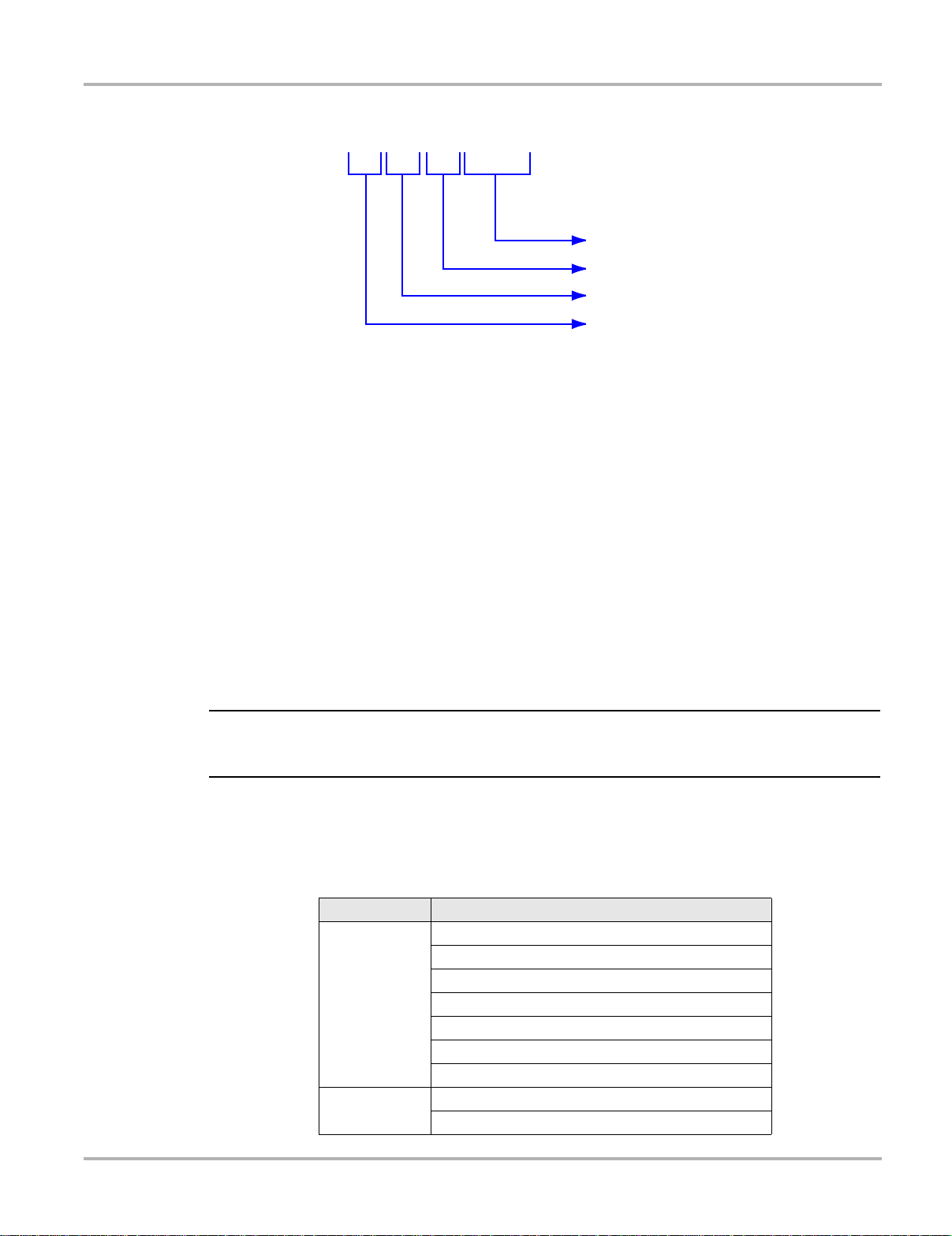
4.6.3 Service $03: Emission-related DTCs
The purpose of this service is to enable the scan tool to obtain stored DTCs from the power train
ECMs that are emission-related.
The OBD-I ECM primarily identifies a faulty signal or a faulty sensor using three steps:
• Signal or component shorted to ground
• Signal or component shorted to battery positive
• No signal or component (open circuit)
For each of these tests, a specific trouble code is set.
With OBD-II/EOBD, expanded diagnostics now includes “rationality” testing. One input signal is
compared against other input signals to de termin e if the read ing is reasona ble, give n the curre nt
operating conditions.
Table 4-3
Diagnostic Trouble Code description
Position Description
P = Power train
1
2
3
4 & 5 Serial numbering of individual components or systems
C = Chassis
B = Body
U = Network
0 = Standardized emission-related trouble code
1 = Manufacturer-specific trouble code
2 = Standardized or Manufacturer-specific trouble code
3 = Standardized or Manufacturer-specific trouble code
0 = Overall system
1 = Secondary air system/Mixture preparation
2 = Fuel system
3 = Ignition system/Misfires
4 = Additional exhaust gas monitoring
5 = Cruise control/Idle speed control
6 = Input/Output signals, Control units
7 = Gearbox/Transmission
8 = Transmission
9 = Transmission
A = Hybrid Propulsion
B = Reserved
16
Page 24
On-Board Diagnostics (OBD) Diagnostic Service Definitions
NOTE:
P0237
Position 4 & 5
Position 3
Position 2
Position 1
Figure 4-3 Example: DTC “P0237”
In this example, definitions listed for Position 3 are only valid for DTCs starting with “P”. For other
codes (C, B, U) there are other definitions. Please refer to ruling OBD standards for more
information.
Code Ranking
OBD-II/EOBD Codes have a priority according to their emission severity , with higher priority codes
overwriting lower priority codes. The priority of the code determines the illumination of the MIL and
the code erase procedure.
Vehicle manufa cturers have implem ented the r anking differently.
4.6.4 Service $04: Clear/Reset Emission-related Diagnostic Data
i It is recommended to perform the Clear Code/Reset function with the engine off and th e ignition
switched on.
The purpose of this service is to clear codes and turn off the MIL. It is recommended to pr int the
DTCs before erasing them, for comparison af ter rep a irs are made.
Clearing the code memory erases all diagnostic information st ated in “Reset Information” below:
Table 4-4 Reset Information (sheet 1 of 2)
Service Items to reset
Status of system monitoring tests
Number of diagnostic trouble codes
Distance travelled while MIL is activated
$01
$02
Number of warm-ups since DTCs cleared
Distance travelled since DTCs cleared
Time run by the engine while MIL is activated
Time since diagnostic trouble codes cleared
Diagnostic trouble code for freeze frame data
Freeze frame data
17
Page 25

On-Board Diagnostics (OBD) Diagnostic Service Definitions
IMPORTANT:
NOTE:
NOTE:
NOTE:
Table 4-4 Reset Information (sheet 2 of 2)
Service Items to reset
$03 Confirmed diagnostic trouble codes
$05 Oxygen sensor test data
$06 Specific on-board monitoring test results
$07 Pending diagnostic trouble codes
The following may occur as well:
• It may also erase engine management adaptive memory (some vehicle manu factur ers only)
when codes are cleared. Depending on the vehicle, adaptive memory ma y not correct it self
without extensive driving.
• Other manufacturer specific actions for clearing and setting may also occur in response to this
request message.
• Normally the MIL automatically turns off after a successful repair , if emissions are normal.
Refer to “Repair validation” on page 14.
For safety and/or technical design reasons, so me ECMs may not respond to this service under all
conditions.
i In most cases, once a MIL is deactivated, the original code remains in memory until forty to eighty
warm-up cycles are completed without the fault reappearing.
4.6.5 Service $05: Oxygen Sensor Monitoring Test Results
The purpose of this service is to allow access to the on-board ox ygen sens or monitoring test
results (if implemented).
i For CAN vehicles, Service $05 is not supported. Oxygen sensor test results are implemented in
Service $06. For non-CAN vehicles, manufacturers can use Service $06 as an alter native to
Service $05.
Different manufacturers may use many methods to calculate test results for this service. The scan
tool converts test values and displays them in the st andard units of measurement.
The ECM transmits the latest test results available from the system. Test results are retained by
the ECM, even over multiple ignition OFF cycles, until replaced by the results of a more recent
test. Test results are requested by Test ID. (See Test ID T able).
Test results can be reported either as a co nst ant or as a calculated value, dep ending on the Test
ID. Calculated values are reported with minimum and maximum limits.
i Depending on the manufacturer, calculated values ma y be roun ded off, which means that a test
may fail despite the values reading within min. and max limits.
18
Page 26

On-Board Diagnostics (OBD) Diagnostic Service Definitions
NOTE:
NOTE:
The scan tool checks if the readiness status of oxygen sensors is completed. If the test is not
completed, the scan tool displays a warning.
$08
Rich
$04
Oxygen
Sensor
$02
$01
Output
$03
Lean
$07
Numbers Refer to Test ID
$06 $05
Figure 4-4
T est ID Values Example
$0A $09
i Refer to Table 4-5 for an explanation of the individual Test ID numbers.
Table 4-5 Test ID Table
Test ID No. Description
$01 Rich to Lean sensor threshold voltage (constant)
$02 Lean to Rich sensor threshold voltage (constant)
$03
$04
$05 Rich to Lean sensor switch time (calculated)
$06 Lean to Rich sensor switch time (calculated)
$07 Minimum sensor voltage for test cycle (calculated)
$08 Maximum sensor voltage for test cycle (calculated)
$09 Time between sensor transitions (calculated)
$0A Sensor Period (calculated)
$0B
$0C
Low sensor voltage for switch time calculation
(constant)
High sensor voltage for switch time calculation
(constant)
EWMA (Exponential Weighted Moving Average)
misfire counts for last 10 driving cycles (calculated)
Calculation: 0.1 * (current counts) + 0.9 * (previous
average)
Initial value for (previous average) = 0
Misfire counts for last/current driving cycles
(calculated)
i Not all test values are applied on or supported by all vehicles. Only supported Test IDs appear in
the selection list.
19
Page 27

On-Board Diagnostics (OBD) Diagnostic Service Definitions
1234
Cylinder Bank & O2S Locations, Examples
Figure 4-5 L4 Cylinder Engine with 1 exhaust bank and 1 Catalyst
1— Engine, exhaust bank
2— Sensor 1
3— Catalyst
4— Sensor 2, (heated)
1— Engine, exhaust bank
2— Sensor 1
3— Catalyst
4— Sensor 2, (heated), Bank 1
5— Catalyst
6— Sensor 3 (heated), Bank 1
1234 56
Figure 4-6
L4 Cylinder Engine with 1 exhaust bank and 2 Catalysts
20
Page 28

On-Board Diagnostics (OBD) Diagnostic Service Definitions
V
561A 2A 3A 4A
1B 2B 3B 4B
Figure 4-7 V8 Cylinder Engine with 2 exhaust banks and 3 Catalysts
1— Exhaust Bank X
2— Sensor 1, Bank X
3— Catalyst
4— Sensor 2, (heated), Bank X
5— Catalyst
6— Sensor 3 (heated), Bank X
1A 2A 3A 4A 5A 6A
V
1B 2B 3B 4B 5B 6B
Figure 4-8
1— Exhaust Bank X
2— Sensor 1, Bank X
3— Catalyst
4— Sensor 2, (heated), Bank X
5— Catalyst
6— Sensor 3 (heated), Bank X
V8 Cylinder Engine with 2 exhaust banks and 4 Catalysts
21
Page 29

On-Board Diagnostics (OBD) Diagnostic Service Definitions
IMPORTANT:
4.6.6 Service $06: Specific Monitored Systems Test Results
The purpose of this service is to allow access to the test result s for on-board diagnostic monitoring
tests of specific components or systems that are continuou sly monitored ( CAN only) and
non-continously monitored.
The misfire monitor is an example of a continuously monitored system, a nd th e cat alyst system
would be an example of a non-continously monitored system.
CAN Protocol
For CAN the T est ID Table from Service $05 is us ed. The request message for test values includes
an OBDMID (On-Board Diagnostic Monitor IDentification) that ind ica tes th e infor matio n
requested. Unit information is given with the values. Test values (results) ar e always reported with
the minimum and maximum test limits.
The Test ID Table below is for CAN Protocol only:
Table 4-6
Test ID No. Description
$01 Rich to Lean sensor threshold voltage, (Constant)
$02 Lean to Rich sensor threshold voltage, (Constant)
$03
$04
$05 Rich to Lean sensor switch time, (Calculated)
$06 Lean to Rich sensor switch time, (Calculated)
$07 Minimum sensor voltage for test cycle, (Calculated)
$08 Maximum sensor voltage for test cycle, (Calculated)
$09 Time between sensor transitions, (Calculated)
$0A Sensor Period, (Calculated)
$0B
$0C
Test ID Table for CAN Protocol
Low sensor voltage for switch time calculation,
(Constant)
High sensor voltage for switch time calculation,
(Constant)
EWMA (Exponential Weighted Moving Average)
misfire counts for last 10 driving cycles (calculated)
Calculation: 0.1 * (current counts) + 0.9 * (previous
average)
Initial value for (previous average) = 0
Misfire counts for last/current driving cycles
(calculated)
If an OBDMID has not been completed at least once since Service $04 or battery disconnect, then
the following properties of the parameter are set to zero by the ECM:
• Test Value (Results)
• Minimum Test Limit
• Maximum Test Limit
22
Page 30

On-Board Diagnostics (OBD) Diagnostic Service Definitions
Non CAN Protocol
The vehicle manufacturer is responsible for assigning Test IDs and Component IDs for tests o f
different systems and componen t s. The la test test re sult s a re to be r et aine d, even over multiple
ignition OFF cycles, until replaced by more recent test results. Test results are r equested by Test
ID. Test results are reported only for supported combinations of test limit type and co mponen t ID
and are reported as positive (unassigned) values. Service $06 test valu es and limit s ar e raw
values that not scaled.
To date, only some manufacturers have provided conversion factors for technicians to use this
data. See the example below for a US Ford version of Service $06 Cat alytic Converter test results.
Table 4-7
Test ID Comp ID Test Value Min. Max
$10 $11
$10 $21
Service $06 Catalytic Converter test results
Cat monitor Switch ratio
Bank1
Cat monitor Switch ratio
Bank2
45 0 48
42 0 48
Ford conversion factor: multiply the value by 0.0156 to get a value from 0 to 1.0.
Table 4-8 Calculated values
Item Factor Result
Bank 1 45 * 0.0156 0.702
Bank 2 42 * 0.0156 0.655
Threshold 48 * 0.0156 0.749
This catalyst is about to fail. Normal readings for a good catalyst should be approximately
0to0.1(switch ratio).
Service $06 Notes
Consider the following when performing this service:
• If in Service $01 (Readiness Test St atus) one of th e test s is not completed, a wa rning
message displays indicating that the values may be invalid or not available.
• Not all test values are applicable or supported by all vehicles. Only supported Test IDs appear
on the selection list. T o be able to select none supported T est IDs, the last item of the selection
list is Manual Selection of Test ID.
• This service can be used as an alternative to Service $05 to report oxygen sensor test results
The values are not converted and are displayed in st andar d unit s.
4.6.7 Service $07: Emission-related DTCs detected during Current or
Last Completed Drive Cycle (Pending Codes)
The purpose of this service is to enable the scan tool to obt ain “pen ding” o r maturing d iagnostic
trouble codes. These are codes for emission-related comp onent s or systems that are tested or
continuously monitored during normal driving conditions th at were detected durin g the current o r
last completed driving cycle.
23
Page 31

On-Board Diagnostics (OBD) Diagnostic Service Definitions
Test results for these components or systems are reported in the same format as the DTCs in
Service $03; refer to “Service $03: Emission-related DTCs” on p age 16.
The intended use of this service is to assist the service techn ician af te r a vehicle r ep air and af ter
clearing diagnostic information, by reporting test results after a sing le driving cycle.
• If a test failed during the driving cycle, the DTC associated with that test will be reported. If the
pending fault does not occur again within 40 to 80 warm-up cycles, the fault is automatically
cleared from memory.
• T est results repo rted by this service do not necessarily indicate a faulty component or system.
If test results indicate a failure again after additional driving, then a DTC will set with Service
$03, indicating a faulty component or system. The MIL will be illuminated.
This service can always be used to request the results of the latest test, independent of the setting
of a DTC.
4.6.8 Service $08: On-board Activation Tests
This service controls the operation of vehicle components, tests or systems. These tests are also
known as “On-Board Activation Tests”.
4.6.9 Service $09: Vehicle Information
The purpose of this service is to enable the scan tool to request vehicle specific vehicle
information such as:
• Vehicle Identification Number (VIN)
• Calibration IDs
• Calibration V erifica tion Numbers (CVN, d isplayed as hexadecimal value)
Some of this information may be required by regulations and so me may be desira ble to be
reported in a standard format, if su pported b y the vehicle manu facturer.
4.6.10 Service $09: In-use Performance T racking
This data is used to support possible regulatory requirements for “In-use Performance Tracking”.
Manufacturers are required to implement sof twa re progr ams that track in-use per formance for
each of the following components or systems:
• Catalyst Bank 1
• Catalyst Bank 2
• Primary Oxygen Sensor Bank 1
• Primary Oxygen Sensor Bank 2
• Evaporative Leak Detection System
• EGR System
• Secondary Air System
24
Page 32

On-Board Diagnostics (OBD) Diagnostic Service Definitions
The completion value tracks the number of times that all conditions necessar y fo r a sp eci fic
monitor to detect a malfunction have been encountered. The condition value ind icates the number
of times that the vehicle has been operated in the specified conditions.
OBD Monitoring Conditions—displays the number of times that the veh icle has be en operated
in the specified OBD monitoring conditions.
Engine Starts—displays the count of the number of times that the engine has been started.
Catalyst Monitor Completion Bank X—displays the number of times that all cond itions
necessary to detect a Catalyst System Bank 1 or 2 malfunction have been encountered.
Catalyst Monitor Conditions Ban k X—disp lays the nu mber of time s that the veh icle has b een
operated in the specified Catalyst monitoring conditions.
O2 Sensor Monitor Completion Bank X—displays th e number o f time that all co nditions
necessary to detect an Oxygen Sensor Bank 1 or 2 malfunction have been encoun tered.
O2 Sensor Monitor Conditions Bank X—displays the number of times that the ve hicle has been
operated in the specified Oxygen Sensor monitoring conditions.
EGR Monitor Completion—displays the number of time that all conditions necessary to dete ct
an EGR system malfunction have been encountered.
EGR Monitor Conditions—displays the number of times that the vehicle has been operated in
the specified EGR system monitoring conditions.
Secondary Air Monitor Completion—displays the number of time th at all conditions necessary
to detect a Secondary Air system malfunction have been encounte red.
Secondary Air Monitor Conditions—displays the number of times that the vehicle has been
operated in the specified Secondary Air system monitoring conditions.
EV AP Monitor Completion—displays the number of tim e that all conditions necessary to detect
an EV AP system le ak malfunction ha ve be en encounter ed.
EV AP Monitor Conditions—displays the n umber of times that the vehicle has been o perated in
the specified EVAP system leak malfunction monitoring conditions.
25
Page 33

Chapter 5 Navigation
ID:$ 11
RPM(1/min.) 1800
TPS(%) 50.2
IAT(°C) 88
ECT(°C) 104
A/F Rate(g/s) 11.52
LIVE DATA
1
2
The following sections describe screen layout, how to navigate the interface, and h ow to make
selections using screen menus and buttons. The various types of screen messa ges are al so
explained in this section.
5.1 Screen Layout
MICROSCAN™ display screens typically consist of two sections:
Figure 5-1
1— Title bar—shows the type of test being performed and the power source
2— Main body—shows test data
One of three basic types of screen displays for most scan tool procedures:
Sample screen
• Trouble code screens
• Menu screens
• Data screens
Each type is explained below.
5.2 T rouble Code Screens
A trouble code screen displays a list of the diagnostic trouble codes (DTCs) stor ed in the
electronic control module (ECM) of the test vehicle. The MICROSCAN automatically tests for
codes on connection to a vehicle data link connector (DLC) on power up . An “establishing
communication” message momentarily displays on the screen while the MICROSCAN gathers
code information. A “No Codes” message displays if there are no stored DTCs in the vehicle ECM.
If there are stored codes, a code report similar to the example shown b elow displays. An arr ow
head in the lower right corner of the screen indicates there are a dditional codes, scroll with the
down (d) button to view the entire list.
26
Page 34

Navigation Menu Screens
IMPORTANT:
Confirmed Codes
TROUBLE CODES
P0115
Intake (A) Camshaft Posit...
Engine Coolant Temperatu...
P0105
Confirmed Codes
TROUBLE CODES
P0115
Coolant Thermostat...
Coolant Thermostat (Coola...
P0128
P0128: Coolant
Thermostat (Coolant Temp
Below Thermostat
Regulating Temperature).
MAIN MENU
Global OBD-2/EOBD
Enhanced Codes
Captured Movies
Settings
Global OBD-2/EOBD Help
Select Protocol
Figure 5-2 Sample code report
A sub-title, which can read Confirmed Codes, Pending Codes, or Permanent Codes, appears at
the top of the report. The sub-title changes as you scro ll through the list if there are mor e than one
type of code in memory. Codes are listed in ascending order with a truncated description on the
line immediately below the DTC. Press Y and a window showing the complete description of the
highlighted DTC opens.
Certain “Enhanced Codes”, which are specific to a p a rticular man ufacturer, do not display in the
standard code list that automatically opens when co nnected to a vehicle. Select Enhance d Codes
from the main menu to view these manufacturer specific DTCs.
5.3 Menu Screens
Menu screens present a list of options from which you can select. Selecting a m enu optio n can
open a test, perform a function, or open a sub-menu of additional choices. A typical “main menu ”
is shown below.
Figure 5-3
Sample DTC description window
Figure 5-4
27
Sample main menu
Page 35

Navigation Menu Screens
GLOBAL OBD-2/EOBD
Current Data
Freeze Frame Data
Confirmed Codes
Clear Codes
O2 Monitors
Non-Cont. Monitors
z To select from a menu:
1. Use the up (b) and down (d) buttons to move the highlight to the desired choice.
2. Press Y to make the selection.
5.3.1 Main Menu
The main menu is the default screen that displays under the following conditio ns:
• The MICROSCAN unit is turned on and powered by the internal battery.
• The MICROSCAN unit is powered by the vehicle but cannot estab lish communication with the
vehicle ECM.
• When exiting from a Trouble Cod es screen.
• When Y is selected from a “No Codes” screen.
The main menu may include the following options:
• Global OBD-2/EOBD—opens a sub-menu of test options.
• Movie—opens a previously recorded data file.
• Settings—opens a menu for configuring the MICROSCAN display characteristics.
• Global OBD-2/EOBD Help—opens a “help” file that explains certain global OBD test s.
• Select Protocol—allows you to choose which communication protocol the scan tool uses.
5.3.2 Global OBD-2/EOBD Menu
The Global OBD2/EOBD menu presents a list of st andard test s fro m which you can cho ose.
Figure 5-5
A brief description of each test is presented here, more de t ailed descr iptions can be fou nd in the
Operations Chapter of this manual.
Sample Global OBD-2/EOBD menu
• Current Data—displays “live” data parameter va lues transmitted by the vehicle ECM.
• Extended Data (Optional)—displays additiona l data values not inclu ded on the standard list.
• Freeze Frame Data—displays certain data values that were captured when a DTC set.
• Confirmed Codes—displays any emissions related DTCs stored in ECM memory.
• Clear Codes—erases DTC and freeze frame records from ECM memo ry.
• O2 Monitors—displays the status of the oxygen (O2) sensor monitors.
• Non-Cont. Monitors—displays the status of the non-con tinuous mon itors.
28
Page 36

Navigation Menu Screens
5.3.3 Exit Menu
The exit menu opens as a “pop-up” when th e N button is pressed from most screens an d offers a
series of functions to choose from. The pop-up presents graphic represent a tions for three
functions and the center option is the one that is activated if th e Y bu tton is presse d.
Table 5-1
Protocol Information
Exit menu graphic definitions
Name Graphic Description
Shows the current communication
protocol, the number of emissions
related DTCs, and the serial number of
MICROSCAN unit.
your
Exit
Settings
Screen Capture
Save Movie
Lock/Unlock
Text/Graph
Min/Max
Returns to the previous screen, this is
the default selection for the exit menu.
Opens a menu for configuring the
MICROSCAN display, this is the
same as the Settings selection from the
main menu.
Saves a copy of the last screen viewed
before the N button was pressed.
Saves a copy of the data recorded in
the data buffer.
Locks or unlocks the parameter
highlighted on the previous screen to
either prevent or allow it to scroll.
Switches the data list between a text
view and a graph view.
Recalibrates the minimum and
maximum data values displayed on a
data graph.
Pause/Play
Clear ECM Memory
Custom Data List
Suspends data collection when viewing
live data to allow closer examination,
and restarts data collection when
viewing paused data.
Erases all data, stored codes, pending
codes, and freeze frame information,
from the vehicle ECM.
Allows you to select which data
parameters display on the data list.
29
Page 37

Navigation Data Screens
NOTE:
GLOBAL OBD-2/EOBD
Current Data
Freeze Frame Data
Confirmed Codes
Clear Codes
O2 Monitors
Non-Cont. Monitors
The up (b) and down (d) buttons scroll the graphics right and left respectively when more than
three options are available. The graphics scroll in a continuous l oop so there is no need to reverse
direction while scrolling.
z To use the Exit menu:
1. Press the N button to open the menu.
2. Press the up (b) button to scroll left or the down (d) button to scroll right until the desired
option is in the center position.
3. Press the Y button to activate the selected function.
5.4 Data Screens
Data screens display serial datastream parameter values, which represent in put and outpu t
information that the ECM is receiving and transmitting to the various actuators, sensors, and
switches in the electronic control system.
Vehicle dat astream information can be displayed in two formats; text view and graph view. Use the
Text/Graph function on the Exit menu to switch between viewing modes.
5.4.1 Text View
Text view screens include a parameter description and a p arameter value. Th e units of the valu e,
such as V for volts, mS for milliseconds, and % for percent, are shown in p arenthe sis af te r the
parameter description. A lock icon appears to the right of th e value if the parameter has been
locked to prevent it from scrolling. Up and down scroll arrows appear to the right of the values
whenever additional parameters are above and belo w those sho wn on the curren t screen.
Figure 5-6
Sample Exit menu
i Parameters display in the order in which they are transmitted by the ECM. Therefore, the display
order can vary considerably depending upon make, model, and yea r.
30
Page 38

Navigation Data Screens
RPM(1/min.) 1800
TPS(%) 50.2
TPS(V) 2.7
IAT(°C) 88
ECT(°C) 104
A/F Rate(g/s) 11.52
LIVE DATA
ECT: Engine Coolant
Temperature (°C)
12 34
LIVE DATA
RPM(1/min.) 1800
TPS(%) 50.2
TPS(V) 2.7
IAT(°C) 88
ECT(°C) 104
A/F Rate(g/s) 11.52
1— Parameter description
2— Parameter value unit
3— Parameter value
4— Lock icon
5— Scroll arrows
Figure 5-7
Up to three parameters can be locked in place to allow side-by-side comparison while in the text
view. Use the L ock/Unlock function on the Exit me nu to lock and release parameters. When a
parameter is locked, it is moved to th e top of the data list, when it is released it returns to its original
position in the data list.
An abbreviated, or short version, of the para meter description i s used so that it fit s on one line.
Highlight a parameter and press Y to open a pop-up with th e complete long p arameter name.
Sample text view screen
5
5
5.4.2 Graph View
Graph view screens include a parameter description a nd a data graph parameter value activity.
The units of the data value, the lock icon, a nd the scr oll arrows are similar as for text view. The
short parameter name is shown, but pressing Y opens a pop-up to reve al the complete name. Due
to the height of the data graphs, only two par ameters are displa yed at a time and only o ne
parameter can be locked. A parameter move s to the top o f the da t a list when it is locked. If mor e
than on parameter was locked when graph view i s selected, the top p arameter in the list remains
locked and the others return to their original positions in the data list.
Figure 5-8
Sample long parameter name pop-up
31
Page 39

Navigation Data Screens
IMPORTANT:
LIVE DATA
TPS(%)
50.2
RPM(1/min.)
1850
13 4 5
6
6
2
1— Parameter description
2— Current data value
3— Parameter value unit
4— Parameter data graph
5— Lock icon
6— Scroll arrows
Figure 5-9
Sample graph view screen
The MICROSCAN constructs the graphs from left to right across the screen and generates a point
on the graph for each data stream tr ansmission from the ECM. How quickly the g raph area of the
screen is filled depends upon the transmission speed of the ECM, so expect g raphing spe ed
differences between makes and models. The screen is wide e nough to disp lay 64 dat a point s on
a graph. Once the graph fills the screen older point at the left edge are hidden as new points on
the right edge are added. The value of the current sample point displays below the pa rameter
name alongside the graph.
A special cursor function that allows you to scroll across the data gr aphs is ava ilable on the exit
menu in graph view. When selected a cursor appears as a vertical line on the graphs, arrows on
either side of the graph show the scrolling directio n has cha nged, an d a fr ame counte r the sh ow
the relative position of the cursor displays in the title bar. The sampled value at the point of the
cursor displays below the parameter description.
1— Cursor
2— Frame counter
Y ou cannot scroll up and down through the data list in cursor mode. Make sure the two p arameters
you want to examine are on the screen before selecting the curso r mode.
LIVE DATA
RPM(1/min.)
1225
TPS(%)
23.7
Figure 5-10
12
28 64
Sample graph with cursor
32
Page 40

Navigation Screen Messages
5.5 Screen Messages
There are four types of on-screen messages:
• Loading and connecting
• Confirmations
• Warnings
• Errors
5.5.1 Loading and Connecting Messages
Loading and connecting messages display when the MICROSCAN unit is performing an internal
operation, such as loading a database, initiating a test, or esta blishing communications with the
vehicle. The message automatically clears once the internal operation is complete.
5.5.2 Confirmation Messages
Confirmation messages inform you when you are about to perform an actio n that cannot be
reversed or when an action that requires your confirm ation to co ntinue has b een initiated.
When a response is not required, the message displays briefly before disappearing.
5.5.3 Warning Messages
Warning messages inform you wh en co mpleting the selected action may result in an irreversible
change or loss of data.
5.5.4 Error Messages
Error messages inform you when a system or procedural error has occurred. Examples of
possible errors include a disconnected cable, a poor connection, or some o ther mechanical failure
that prevents the tool from communicating with the vehicle.
33
Page 41

Chapter 6 Operations
This chapter details the tests and procedur es that are ava ilable from th e main me nu, it includes
the following sections:
• “Global OBD-2/EOBD” on page 34
• “Movie” on page 39
• “Settings” on page 39
• “Global OBD-2/EOBD Help” on page 40
• “Select Protocol” on page 40
6.1 Global OBD-2/EOBD
When Global OBD-2/EOBD is selected a service menu that lists all of the tests available on the
identified vehicle. Menu choices typically in clu de:
• Readiness Status
• Current Data
• Freeze Frame Data
• Confirmed Codes
• Clear Codes
• O2 Monitors
• Non-continuous Monitors
• Pending Codes
• Request Control of On-Board System
• Vehicle Information
6.1.1 Readiness St atus
Designated OBD Mode $00, this selection opens a menu of available test s on monitored systems.
Selecting Readiness St atus from the m ain menu opens a su bmenu with the fo llowing options:
• Complete since DTC Cleared
• Enable Status this Cycle
• Complete this Cycle
Each selection opens a listing of test results.
34
Page 42

Operations Global OBD-2/EOBD
READINESS STATUS
ID: $ 11
Misfire Complete
Fuel System Complete
Catalyst Complete
O2 Sensor Not Complete
O2 Heater Not Complete
RPM(1/min.) 1800
TPS(%) 50.2
TPS(V) 2.7
IAT(°C) 88
ECT(°C) 104
A/F Rate(g/s) 11.52
LIVE DATA
Figure 6-1 Sample readiness status report
There are two types of monitored systems:
• Continuously monitored systems—those that impact vehicle emissio ns, and are r equired to
be monitored by OBD regulations.
• Non-continuously monitored systems—those that do not directly impact vehicle emissions,
and are required to be monitored by OBD regulations.
6.1.2 Current Dat a
Designated OBD Mode $01, this selection displays the current emission related dat a from the
selected electronic control module (ECM) of the vehicle. Displayed data includes ana log inpu t s
and outputs, digital inputs an d output s, and syst em st a tus inform ation broadca st on the veh icle
data stream.
Data can be displayed in either text view or graph vie w . Press N to open the exit m enu and select
Text/Graph to switch view s.
6.1.3 Freeze Frame Data
Designated OBD Mode $02, this selection displays freeze fame dat a for any stor ed emission
related diagnostic trouble codes (DTC). Only one set of freeze fr ame dat a is ret a ined in ECM
memory . In most cases the stored frame is the last DTC that occurred. Certain DTCs, th ose that
have a greater impact on vehicle emission, have a higher priority. In these cases, the highest
priority DTC is the one for which the freeze frame records are re t ained.
Figure 6-2
Sample current data display in text mode
35
Page 43

Operations Global OBD-2/EOBD
RPM(1/min.) 2765
TPS(%) 32.7
TPS(V) 3.4
IAT(°C) 14
ECT(°C) 129
A/F Rate(g/s) 14.31
FREEZE FRAME DATA
Confirmed Codes
TROUBLE CODES
P0115
Intake (A) Camshaft Posit...
Engine Coolant Temperatu...
P0105
Figure 6-3 Sample freeze frame data
Freeze frame data includes a “snap sho t” of crit ical parameter values at the time the DTC set.
6.1.4 Confirmed Codes
Designated OBD Mode $03, this selection displays any stored emission related DTCs reported by
the various ECMs.
The B0XXX, C0XXX, P0XXX, and U0XXX codes are Society of Automotive Engineers (SAE)
controlled and they display along with a description. These codes are the same for all
manufactures.
The B1XXX, B2XXX, C1XXX, C2XXX, P1XXX, P3XXX, U1XXX, and U2XXX codes are
manufacturer controlled, refer to manufacturer dat a for in formation.
6.1.5 Clear Codes
Designated OBD Mode $04, this selection is used to erase all emission related diagnostic data
such as, DTCs, freeze frame data, and test result s from th e memor y of the sele cted ECM. A
confirmation message displays when Clear Codes is selected, press Y to continue and follow the
on screen instructions.
Figure 6-4
36
Sample confirmed codes list
Page 44

Operations Global OBD-2/EOBD
To clear DTCs,
Freeze Frame,
Test Results, and
Readiness Monitors
Key on, Engine off
Press Y; Press N to exit
CLEAR CODES
Figure 6-5 Sample clear codes confirmation message
6.1.6 O2 Monitors
Designated OBD Mode $05, this selection opens a sub-menu of test s available fo r the oxygen
sensor (O2S) monitoring system. Tests display on the screen with an identification (ID) number
and an abbreviated description. Complete test names are shown in the t able below.
Table 6-1 O2 Monitor descriptions
Test ID Abbreviated Description Complete Description
$01 R/L Sensor Threshold Volt. Rich to lean sensor threshold voltage
$02 L/R Sensor Threshold Volt. Lean to rich sensor threshold voltage
$03 Low Sensor Volt Switch Time Low sensor voltage switch time
$04 Hi Sensor Volt Switch Time High sensor voltage switch time
$05 R/L Sensor Switch Time Rich to lean sensor switch time
$06 L/R Sensor Switch Time Lean to rich sensor switch time
$07 Test Cycle Min Sensor Volt Test cycle minimum sensor voltage
$08 Test Cycle Max Sensor Volt Test cycle maximum sensor voltage
$09 Time Between Sensor Trans Time between sensor transitions
6.1.7 Non-Cont. Monitors
Making a selection displays and all of the pertinent O2S p arameters for the specific test.
Designated OBD Mode $06, this selection opens a menu of available test s on non-con tinuously
monitored systems. These are systems that do not directly impact vehicle emissions, but are
required to be monitored by OBD regulations. Tests display on the screen with an i dentification
(ID) number and an abbreviated description.
Table 6-2 Non-continuous Monitor descriptions (sheet 1 of 2)
Test ID Abbreviated Description Complete Description
$21 to $24 Catalyst Bn
$31 to $34 EGR Bn
$39 EVAP (cap off)
$3A EVAP (0.090)
$3B EVAP (0.040)
37
Page 45

Operations Global OBD-2/EOBD
PENDING CODES
P0113
Intake Air Temperatu...
Table 6-2 Non-continuous Monitor descriptions (sheet 2 of 2)
Test ID Abbreviated Description Complete Description
$3C EVAP (0.020)
$3D Purge Flow
$41 to $50 O2 Sensor Htr Bn Sm
$61 to $64 Heated Cat. Bn
$71 to $74 2nd Air n
$81 to $84 Fuel System Bank n
$A1 Misfire General
$A2 to $AD Misfire Cyl n Data
Making a selection displays and all of the pertinent p arameter s for the specific test.
6.1.8 Pending Codes
Designated OBD Mode $07, this selection opens a record of any pendin g codes that set during the
last completed drive cycle. Pending codes are those whose symptoms must occur during more
than one consecutive drive cycle before an actual DTC is set. The code list appears similar to the
standard DTC list.
6.1.9 Request Control of On-board System
6.1.10 V ehicle Information
Figure 6-6
Designated OBD Mode $08, this selection enables bidirectional control of the ECM. In this mode
the scan tool transmits control commands to operat e the vehicle system. This function is useful in
determining how well the ECM responds to a command.
Designated OBD Mode $09, this selection opens a sub-menu that includes:
Sample pending codes list
• Read vehicle identification
• In-use performance tracking
Read vehicle identification displays the vehicle identification numb er (VIN) , the calib ration
identification, and the calibration verification number (CVN) of the test vehicle.
38
Page 46

Operations Movie
CAPTURED MOVIES
Data Capture 1
Data Capture 2
Data Capture 3
Data Capture 4
Data Capture 5
In-use performance tracking displays a record of monitored data. It is basically shows the numb er
of times each of the monitor tests have been completed.
6.2 Movie
This main menu option allows you to open data saved o n the MICROSCAN unit. Saved d at a
includes datastream recordings (movies) as well as individu al screen captu res. A list of sa ved
data displays when Movie is selected from the main menu.
6.3 Settings
Figure 6-7
Data is listed on the menu in the order in which it was saved with the most recent at the top of the
list. A movie includes all of the data and you can scroll up and d own through the list. A screen
capture, or snapshot, includes only what was visible at the time it was taken, other data cannot be
scrolled into view .
This main menu option allows you to select the language for the MICROSCAN display and how
units of measurement display in the data list s . English is the d efault language and Me tric is the
default measurement units.
Sample movie menu
z To change the language setting:
1. Scroll to highlight Settings on the main menu and press Y to select.
A sub-menu of language options displays.
2. Highlight the desired language and press Y to select.
Select Units from the main menu to choose between US Standard or Metric units of measure for
certain data para meters.
Table 6-3 Units of measurement—defaults and options
Measurement Metric US Standard
Temperature degrees Celsius (°C) degrees Fahrenheit (°F)
Air Pressure (including
manifold pressure)
Pressures (all others) kilopascal (kPa) pounds per square inch (psi)
Vehicle Speed kilometers per hour (kph) miles per hour (mph)
kilopascal (kPa) inches of mercury (“Hg)
39
Page 47

Operations Global OBD-2/EOBD Help
GLOBAL OBD-2/EOBD HELP
P0108:
MAP/BARO Circuit High Input
Possible Causes:
Short to Power Circuit;
Faulty BARO Sensor;
Faulty ECM;
GLOBAL OBD-2/EOBD HELP
Service MODE $01:
Current Powertrain Data
System Readiness Test
Display:
MIL or malfunction control;
6.4 Global OBD-2/EOBD Help
This main menu option allows you to access information designed to assist you in making a quick
and accurate diagnosis. Selecting opens a menu with two options:
• Code Tips—provides specific code information that includes setting conditions, test tips, and
probable causes.
• Mode Definitions—provides detailed descriptions of the OBD operating modes and
procedures for performing tests and clearing mo nitors.
Code tips are arranged by group s and you need to navigate through a series of sub-menus to get
to the desired code. Most tips contain more information than will fit on a single screen, scroll to
view the entire tip.
Selecting Mode Definitions opens a sub-menu of modes. Highlight the desired mode a nd press Y
to open the definition. scroll down as needed to view the entire defini tion.
6.5 Select Protocol
This main menu option allows you to select which communication protocol the MICROSCAN unit
uses to retrieve data from the ECM. For most instances, the MICROSCAN software automatically
determines which protocol to use based on the signals received from the ECM.
When the MICROSCAN is connected to the DLC it transmits an inquiry signal and looks for
responses from the vehicle ECMs to determine the protocol. In certain cases a non-emissions
ECM may respond first on a different commun ication line tha n what is used fo r the
emissions-related ECMs. When this happens, the MICROSCAN cannot retrieve DT C and other
pertinent data because it is not receiving the correct data. Th e Select Protocol o ption allows you
Figure 6-8
Figure 6-9
40
Sample code tip
Sample mode definition
Page 48

Operations Select Protocol
SELECT PROTOCOL
ISO 15765-4 (CAN)
ISO 9141-2
ISO 14230-4 (KWP2000)
SAE J1850 (PWM)
SAE J1850 (VPW)
to choose the correct communications link in the rare inst ances when this hap pens. Sele cting
opens a sub-menu.
Figure 6-10
Scroll and press Y to select from the menu.
Sample select protocol menu
41
Page 49

Chapter 7 Data Parameters
NOTE:
Mode $01 and $02 services involve evaluating the vehicle dat a str eam p ara meter value s. This
section provides definitions for the values that display on the viewing screen, along with diagnostic
tips. The information is presented in three ways:
• “Long parameter names” on page 42—lists paramete rs by their comp lete name s
• “Short parameter names” on page 46—lists parameters by their common acro nym
• “DTC association” on page 50—lists parameter names by their correspond ing diagno stic
trouble code (DTC)
Depending upon the vehicle being tested and other va riables, th e screen may display e ither the
long or short parameter names on the data list. The numeric defini tions are based on the last three
characters of the diagnostic trouble code. Refer to “Service $03: Emission-related DTCs” on
page 16 information on DTC structure.
7.1 Long Parameter Names
Table 7-1 lists data parameter definitions alphabetically by their complete name. The complete
name typically displays when viewing data in text mode.
i Counters (like cylinder bank or sensor position) in a parameter name are represen ted by a ‘y’ or
‘x’ in the table.
The vehicle ECM determines the parameter data list, no t all par ameters display on every ve hicle.
Table 7-1
ABSOLUTE LOAD VALUE
ABSOLUTE THROTTLE
POSITION–/B/C
ACCELERATOR PEDAL
POSITION x
AIR FLOW RA T E
Long parameter names (sheet 1 of 4)
Parameter Description for long parameter
Value is presented as a percentage and ranges from 0 to 100 for
naturally aspirated engines, and from 0 to 400 for boosted
engines.
On boosted engines the actual figure displayed is very much
depending on how much boost is used. The higher the boost used,
the higher Absolute Load Value will be.
Shows the absolute throttle position. The output signal is a
proportional percentage to the input voltage (when proportional) or
100% minus the proportional percentage (when inversely
proportional).
See PID $45 for the relative position.
Shows the absolute pedal position. The output signal is a
proportional percentage to the input voltage (when proportional) or
100% minus the proportional percentage (when inversely
proportional).
Shows the flow rate of the intake air as measured by the Mass Air
Flow (MAF) sensor.
42
Page 50

Data Parameters Long Parameter Names
Table 7-1 Long parameter names (sheet 2 of 4)
Parameter Description for long parameter
AMBIENT AIR
TEMPERATURE
BAROMETRIC PRESSURE
CALCULATED LOAD VALUE
CATALYST TEMPERATURE
Bx–Sy
COMMANDED EGR
COMMANDED
EQUIVALENCE RATIO
COMMANDED
EVAPORATIVE PURGE
COMMANDED SEC. AIR
STATUS
Can be obtained from an AAT sensor directly or deducted by the
ECM from other sensor signals.
Can be obtained from a BARO or MAP sensor directly or deducted
by the ECM from other sensor (MAF) signals. If the value at
'ignition key on' and certain driving conditions is stored into a
memory, clearing the memory may lead to inaccurate BARO
values.
The ECM calculates the engine load by dividing the actual
manifold airflow volume (Otto engines) or actual fuel flow (Diesel
engines) by the maximum possible volume with a factor for
pressure and temperature compensation. Correlates with the
engine vacuum. Value is presented as a percentage and ranges
from 0 to 100.
Shows the catalyst substrate temperature for the mentioned bank
or the temperature of the mentioned bank and oxygen sensor. Can
be obtained from a sensor directly or deducted by the ECM from
other sensor signals.
Shows the status of the Exhaust Gas Recirculation system
between 0% (no flow) and 100% (max. flow, max. duty cycle)
Shows the Air/Fuel ratio as commanded by the ECM. To obtain the
actual Air/Fuel ratio, multiply the stoichiometric Air/Fuel ratio by the
equivalence ratio. Conventional oxygen sensors shows the ratio
when in Open Loop only. In Closed Loop '1.0' is shown. Wide
range, or linear, oxygen sensors show the ratio in Open Loop and
Closed Loop.
Shows the status of the Evaporative Purge Control Valve between
0% (no flow) and 100% (max. flow, max. duty cycle)
Shows the position of the Secondary Air system (upstream or
downstream of the first catalytic converter) and/or its status.
COMMANDED THROTTLE
ACT.CONTROL
CONTROL MODULE
VOLTAGE
DISTANCE SINCE DTCs
CLEARED
DISTANCE WHILE MIL
ACTIVE
EGR ERROR
Shows the status of the Throttle Actuator Control between 0%
(closed throttle) and 100% (wide open throttle)
Shows the power input to the ECM. This is not automatically equal
to the battery voltage!
Accumulated distance since the DTCs were cleared. The
maximum number is 65535. To set to 0, reset all DTCs
Conditions for this counter:
1. Resets to zero when MIL state changes from 'deactivated' to
'activated' by the ECM.
2. Accumulates counts in km if MIL is activated (ON).
3. Does not change value while MIL is not activated (OFF).
4. Resets to zero if diagnostic information is cleared either by
service $04 or 40 warm-up cycles without MIL activated.
5. Does not wrap to zero if value is maximum (65535).
The Exhaust Gas Recirculation system control and feedback
devices differ, therefore no 'actual' or 'commanded' status can be
shown. The value is (actual EGR - commanded EGR),
commanded EGR. E.g. (5%-10%)/10%=-50%
43
Page 51

Data Parameters Long Parameter Names
Table 7-1 Long parameter names (sheet 3 of 4)
Parameter Description for long parameter
Shows the temperature as measured by either the engine coolant
ENGINE COOLANT
TEMPERATURE
ENGINE RUN WITH MIL
ACTIVE
ENGINE SPEED Engine speed as calculated by the ECM, based on various signals.
EQUIVALENCE RATIO Bx-Sy
EVAP SYSTEM VAPOR
PRESSURE
FUEL LEVEL INPUT
temperature sensor or the cylinder head temperature sensor. If
neither of these sensors are available, the engine oil temperature
may be shown instead.
Conditions for this counter:
1. Resets to zero when MIL state changes from deactivated to
activated by this ECM.
2. Accumulates counts in minutes if MIL is activated (ON)
3. Does not change value while MIL is not activated (OFF)
4. Resets to zero if diagnostic information is cleared either by
service $04 or 40 warm-up cycles without MIL activated
5. Does not wrap to zero if value is maximum (65535).
Status of the oxygen sensor in V or as a ratio. Designed for linear
or wide-ratio oxygen sensors.
See also PID $14 and up or $34 and up.
Evaporative system vapor pressure, if used by the control module.
Can be obtained from a fuel pressure sensor in the tank or in the
evaporative system vapor line.
Shows the nominal fuel tank liquid fill capacity. For gaseous fuels
the percentage of usable fuel capacity is shown. May either be
obtained directly from a dedicated sensor, or calculated by the
ECM based on other sensor signals.
FUEL PRESSURE GAUGE
FUEL SYSTEM x
IGNITION TIMING ADVANCE
INT AKE AIR TEMPERATURE
INT AKE MAP
LONG TERM FUEL TRIM
BANK x
NR OF WARM-UPS SINCE
DTCs CLEARED
O2S BANK x, SENSOR y
Shows the fuel rail pressure at the engine relative to the
atmosphere (gauge pressure).
Fuel System 'x' does not normally refer to injector banks. It is
intended to represent different fuel systems (for multi-fuel vehicles)
that can independently enter and exit 'Closed Loop'. 'Closed Loop'
means the fuel control system uses the oxygen sensor signal.
Banks of injectors on a V engine are generally not independent
and use the same closed loop criteria.
Ignition timing spark advance fo r cylin der #1. If timing is retarded,
the value will be negative.
Shows the intake manifold air temperature as obtained from a
sensor or as calculated by the ECM (using other inputs).
Shows the absolute pressure in the intake manifold as measured
by the MAP sensor.
Shows the correction used by the Closed Loop and Open Loop
fuel algorithm at the moment this parameter is requested. Negative
values indicate a 'lean' condition, positive values a 'rich' condition.
0% correction will be shown if no correction is used in Open Loop.
A warm-up cycle is valid if the coolant temperature rises, after
starting the engine, at least 22 °C/40 °F and reaches at least 70
°C/160 °F (60 °C/140 °F for Diesel engines). The maximum
number is 255. To set to 0, reset all DTCs.
Shows the presence of oxygen sensor number 'y' per bank 'x'
(group of cylinders). Sensor 1 is closest to the en g i ne
44
Page 52

Data Parameters Long Parameter Names
Table 7-1 Long parameter names (sheet 4 of 4)
Parameter Description for long parameter
O2S CURRENT BANK x,
SENSOR y
O2S VOL TAGE BANK x,
SENSOR y
OBD REQUIREMENTS Shows the OBD requirements that the vehicle was designed for
POWER TAKE OFF (PTO)
STATUS
RELATIVE FUEL PRESSURE
RELATIVE THROTTLE
POSITION
SHORT TERM FUEL TRIM
BANK x
SHORT TERM FUEL TRIM
Bx-Sy
TIME SINCE DTCs
CLEARED
Status of the oxygen sensor in mA or as a ratio. Designed for linear
or wide-ratio oxygen sensors.
See also PID $14 and up or $24 and up.
Shows the status of the oxygen sensor in V or percentages.
Designed for conventional 0 - 1 V oxygen sensors. Sensors with a
different full scale will be adapted. Negative percentages or 0 V
indicate a 'lean' condition. Positive percentages or 1 V indicate a
'rich' condition.
See also PID $24 and up or $34 and up.
Shows Power Take Off (PTO) status.
Shows the fuel rail pressure at the engine relative to the manifold
vacuum.
Shows the 'learned' throttle position. Due to the 'closed throttle
offset', Wide Open Throttle will be much less than 100%. See PID
$11, $47 and $48 for the absolute position.
Shows the correction used by the Closed Loop fuel algorithm.
Negative values indicate a 'lean' condition, positive values a 'rich'
condition. A 0% correction is shown if the fuel system is operating
in Open Loop.
Shows the status of the oxygen sensor in V or percentages.
Designed for conventional 0 - 1 V oxygen sensors. Sensors with a
different full scale will be adapted. Negative percentages or 0 V
indicate a 'lean' condition. Positive percentages or 1 V indicate a
'rich' condition.
See also PID $24 and up or $34 and up.
Accumulated time since the DTCs were cleared. The maximum
number is 65535. To set to 0, reset all DTCs
TIME SINCE ENGINE START
VEHICLE SPEED
The incrementing counter starts when the engine runs. It freezes if
the engine stalls. It resets if the ECM powers up and when the
ignition key enters the 'key-on, engine off' position.
Shows the vehicle speed as obtained from a sensor or as
calculated by the ECM (using other inputs).
45
Page 53

Data Parameters Long Parameter Names
NOTE:
7.1.1 Short Parameter Names
Table 7-2 lists data parameter definitions alphabetically by their abbreviated name. As there is
less display space available on the screen in graphing mode, shor t p aram eter nam es display.
i Counters (like cylinder bank or sensor position) in a parameter name are represen ted by a ‘y’ or
‘x’ in the table.
The vehicle ECM determines the parameter data list, no t all par ameters display on every ve hicle.
Table 7-2
AAT
AIR_STAT
APP_x
BARO
CATEMPx/y
CLR_DIST
CLR_TIME
ECT
ECT_ERR
ECT_PCT
EQ_RAT
Short parameter names (sheet 1 of 4)
Parameter Description for short parameter
Can be obtained from an AAT sensor directly or deducted by the
ECM from other sensor signals.
Shows the position of the Secondary Air system (upstream or
downstream of the first catalytic converter) and/or its status.
Shows the absolute pedal position. The output signal is a
proportional percentage to the input voltage (when proportional) or
100% minus the proportional percentage (when inversely
proportional).
Can be obtained from a BARO or MAP sensor directly or deducted
by the ECM from other sensor (MAF) signals. If the value at
'ignition key on' and certain driving conditions is stored into a
memory, clearing the memory may lead to inaccurate BARO
values.
Shows the catalyst substrate temperature for the mentioned bank
or the temperature of the mentioned bank and oxygen sensor. Can
be obtained from a sensor directly or deducted by the ECM from
other sensor signals.
Accumulated distance since the DTCs were cleared. The
maximum number is 65535. To set to 0, reset all DTCs
Accumulated time since the DTCs were cleared. The maximum
number is 65535. To set to 0, reset all DTCs
Shows the temperature as measured by either the engine coolant
temperature sensor or the cylinder head temperature sensor. If
these sensors are not available, the engine oil temperature may be
shown instead.
The Exhaust Gas Recirculation system control and feedback
devices differ, therefore no 'actual' or 'commanded' status can be
shown. The value is (actual EGR - commanded EGR),
commanded EGR. Example; (5%-10%)/10%=-50%
Shows the status of the Exhaust Gas Recirculation system
between 0% (no flow) and 100% (max. flow, max. duty cycle)
Shows the Air/Fuel ratio as commanded by the ECM. To obtain the
actual Air/Fuel ratio, multiply the stoichiometric Air/Fuel ratio by the
equivalence ratio. Conventional oxygen sensors shows the ration
when in Open Loop only. In Closed Loop '1.0' is shown. Wide
range or linear oxygen sensors show the ratio in Open Loop and
Closed Loop.
46
Page 54

Data Parameters Long Parameter Names
Table 7-2 Short parameter names (sheet 2 of 4)
Parameter Description for short parameter
Status of the oxygen sensor in V or as a ratio. Designed for linear
EQ_RATxy
EVAP_PCT
EVAP_VP
FLI
FRP
FRP_REL
FUELSYSx
IAT
LOAD_ABS
LOAD_PCT
LONGFTx
MAF
MAP
or wide-ratio oxygen sensors.
See also PID $14 and up or $34 and up.
Shows the status of the Evaporative Purge Control Valve between
0% (no flow) and 100% (max. flow, max. duty cycle)
Evaporative system vapor pressure, if used by the control module.
Can be obtained from a fuel pressure sensor in the tank or in the
evaporative system vapor line.
Shows the nominal fuel tank liquid fill capacity. For gaseous fuels
the percentage of usable fuel capacity is shown. Can be obtained
directly from a dedicated sensor or calculated by the ECM from
other sensor signals.
Shows the fuel rail pressure at the engine relative to the
atmosphere (gauge pressure).
Shows the fuel rail pressure at the engine relative to the intake
manifold vacuum.
Fuel System 'x' does not normally refer to injector banks. It is
intended to represent different fuel systems (for multi-fuel vehicles)
that can independently enter and exit 'Closed Loop'. 'Closed Loop'
means the fuel control system uses the oxygen sensor signal.
Banks of injectors on a V-engine are generally not independent
and use the same closed loop criteria.
Shows the intake manifold air temperature as obtained from a
sensor or as calculated by the ECM (using other inputs).
Value is presented as a percentage and ranges from 0 to 100 for
naturally aspirated engines, and from 0 to 400 for boosted
engines.
On boosted engines the actual figure displayed is dependant on
how much boost is used. The higher the boost used, the higher
Absolute Load Value will be.
The ECM calculates the engine load by dividing the actual
manifold airflow volume (Otto engines) or actual fuel flow (Diesel
engines) by the maximum possible volume with a factor for
pressure and temperature compensation. Correlates with the
engine vacuum. Value is presented as a percentage and ranges
from 0 to 100.
Shows the correction used by the Closed Loop and Open Loop
fuel algorithm at the moment this parameter is requested. Negative
values indicate a 'lean' condition, positive values a 'rich' condition.
0% correction will be shown if no correction is used in Open Loop.
Shows the flow rate of the intake air as measured by the Mass Air
Flow (MAF) sensor.
Shows the absolute pressure in the intake manifold as measured
by the MAP sensor.
47
Page 55

Data Parameters Long Parameter Names
Table 7-2 Short parameter names (sheet 3 of 4)
Parameter Description for short parameter
Conditions for this counter:
1. Resets to zero when MIL state changes from 'deactivated' to
'activated' by the ECM.
MIL_DIST
MIL_TIME
O2SLOCxy
O2Sxy
O2Sxy
OBDSUP Shows the OBD requirements that the vehicle was designed for.
PTO_STAT Shows Power Take Off (PTO) status.
RPM Engine speed as calculated by the ECM, based on various signals.
RUNTM
SHRTFTx
SHRTFTxy
SPARKADV
TAC_PCT
2. Accumulates counts in km if MIL is activated (ON)
3. Does not change value while MIL is not activated (OFF)
4. Resets to zero if diagnostic information is cleared either by
service $04 or 40 warm-up cycles without MIL activated
5. Does not wrap to zero if value is maximum (65535).
Conditions for this counter:
1. Resets to zero when MIL state changes from deactivated to
activated by this ECM.
2. Accumulates counts in minutes if MIL is activated (ON).
3. Does not change value while MIL is not activated (OFF).
4. Resets to zero if diagnostic information is cleared either by
service $04 or 40 warm-up cycles without MIL activated.
5. Does not wrap to zero if value is maximum (65535).
Shows the presence of oxygen sensor number 'y' per bank 'x'
(group of cylinders). Sensor 1 is closest to the en g i ne
Shows the status of the oxygen sensor (O2S) in voltage or
percentages. This parameter is designed for a conventional (0
to 1 V range) O2S. Sensors with a different full scale will be
adapted. Negative percentages or below 0.5 V indicates a 'lean'
operating condition. Positive percentages or above 0.5 V indicates
a 'rich' operating condition.
See also PID $24 and up or $34 and up.
Status of the oxygen sensor in mA or as a ratio. Designed for linear
or wide-ratio oxygen sensors.
See also PID $14 and up or $24 and up.
The incrementing counter starts when the engine runs. It freezes if
the engine stalls. It resets if the ECM powers up and when the
ignition key enters the 'key-on, engine off' position.
Shows the correction used by the Closed Loop fuel algorithm.
Negative values indicate a 'lean' condition, positive values indicate
a 'rich' condition. A 0% correction is shown if the fuel system is
operating in Open Loop.
Shows the status of the oxygen sensor (O2S) in voltage or
percentages. This parameter is designed for a conventional (0
to 1 V range) O2S. Sensors with a different full scale will be
adapted. Negative percentages or below 0.5 V indicates a 'lean'
operating condition. Positive percentages or above 0.5 V indicates
a 'rich' operating condition.
See also PID $24 and up or $34 and up.
Ignition timing spark advance fo r cylin der #1. If timing is retarded,
the displayed value is negative.
Shows the status of the Throttle Actuator Control between 0%
(closed throttle) and 100% (wide open throttle)
48
Page 56

Data Parameters Long Parameter Names
Table 7-2 Short parameter names (sheet 4 of 4)
Parameter Description for short parameter
Shows the absolute throttle position. The output signal is a
proportional percentage to the input voltage (when proportional) or
TP/TP_B/TP_C
TP_R
VPWR
VSS
WARM_UPS
100% minus the proportional percentage (when inversely
proportional).
See PID $45 for the relative position.
Shows the 'learned' throttle position. Due to the 'closed throttle
offset', Wide Open Throttle will be much less than 100%.
See PID $11, $47 and $48 for the absolute position.
Shows the power input to the ECM. This is not automatically equal
to the battery voltage!
Shows the vehicle speed as obtained from a sensor or as
calculated by the ECM (using other inputs).
A warm-up cycle is valid if the coolant temperature rises, after
starting the engine, at least 22 °C/40 °F and reaches at least 70
°C/160 °F (60 °C/140 °F Diesel). The maximum number is 255. To
set to 0, reset all DTCs.
49
Page 57

Data Parameters Long Parameter Names
NOTE:
7.1.2 DTC Association
Table 7-3 lists parameter names (short and long) by their associated diagnostic trouble code
(DTC) in numerically ascending order.
i The value listed is the last three characters of the DTC, a “$” indicates a variable value.
Table 7-3
DTC association (sheet 1 of 4)
DTC Name, short Parameter Name, long
$03 FUELSYS1 FUEL SYSTEM 1
$03 FUELSYS2 FUEL SYSTEM 2
$04 LOAD_PCT (%) CALCULATED LOAD VALUE (%)
$05 ECT (°C) ENGINE COOLANT TEMPERATURE (°C)
$06 SHRTFT1 (%) SHORT TERM FUEL TRIM BANK 1 (%)
$07 LONGFT1 (%) LONG TERM FUEL TRIM BANK 1 (%)
$08 SHRTFT2 (%) SHORT TERM FUEL TRIM BANK 2 (%)
$09 LONGFT2 (%) LONG TERM FUEL TRIM BANK 2 (%)
$0A FRP (kPa) FUEL PRESSURE GAUGE (kPa)
$0B MAP (kPa) INTAKE MAP (kPa)
$0C RPM (1/min.) ENGINE SPEED (1/min.)
$0D VSS (km/h) VEHICLE SPEED (km/h)
$0E SPARKADV (°) IGNITION TIMING ADVANCE (°)
$0F IAT (°C) INTAKE AIR TEMPERATURE (°C)
$10 MAF (g/s) AIR FLOW RATE (g/s)
$11 TP (%) ABSOLUTE THROTTLE POSITION (%)
$12 AIR_STAT COMMANDED SEC. AIR STATUS
$13 O2SLOC11 O2S BANK 1 - SENSOR 1
$13 O2SLOC12 O2S BANK 1 - SENSOR 2
$13 O2SLOC13 O2S BANK 1 - SENSOR 3
$13 O2SLOC14 O2S BANK 1 - SENSOR 4
$13 O2SLOC21 O2S BANK 2 - SENSOR 1
$13 O2SLOC22 O2S BANK 2 - SENSOR 2
$13 O2SLOC23 O2S BANK 2 - SENSOR 3
$13 O2SLOC24 O2S BANK 2 - SENSOR 4
$14 O2S11 (V) O2S VOLTAGE BANK 1 - SENSOR 1 (V)
$14 SHRTFT11 (%) SHORT TERM FUEL TRIM B1-S1 (%)
$15 O2S12 (V) O2S VOLTAGE BANK 1 - SENSOR 2 (V)
$15 SHRTFT12 (%) SHORT TERM FUEL TRIM B1-S2 (%)
$16 O2S13 (V) O2S VOLTAGE BANK 1 - SENSOR 3 (V)
$16 SHRTFT13 (%) SHORT TERM FUEL TRIM B1-S3 (%)
50
Page 58

Data Parameters Long Parameter Names
Table 7-3 DTC association (sheet 2 of 4)
DTC Name, short Parameter Name, long
$17 O2S14 (V) O2S VOLTAGE BANK 1 - SENSOR 4 (V)
$17 SHRTFT14 (%) SHORT TERM FUEL TRIM B1-S4 (%)
$18 O2S21 (V) O2S VOLTAGE BANK 2 - SENSOR 1 (V)
$18 O2S31 (V) O2S VOLTAGE BANK 3 - SENSOR 1 (V)
$18 SHRTFT21 (%) SHORT TERM FUEL TRIM B2-S1 (%)
$18 SHRTFT31 (%) SHORT TERM FUEL TRIM B3-S1 (%)
$19 O2S22 (V) O2S VOLTAGE BANK 2 - SENSOR 2 (V)
$19 O2S32 (V) O2S VOLTAGE BANK 3 - SENSOR 2 (V)
$19 SHRTFT22 (%) SHORT TERM FUEL TRIM B2-S2 (%)
$19 SHRTFT32 (%) SHORT TERM FUEL TRIM B3-S2 (%)
$1A O2S23 (V) O2S VOLTAGE BANK 2 - SENSOR 3 (V)
$1A O2S41 (V) O2S VOLTAGE BANK 4 - SENSOR 1 (V)
$1A SHRTFT23 (%) SHORT TERM FUEL TRIM B2-S3 (%)
$1A SHRTFT41 (%) SHORT TERM FUEL TRIM B4-S1 (%)
$1B O2S24 (V) O2S VOLTAGE BANK 2 - SENSOR 4 (V)
$1B O2S42 (V) O2S VOLTAGE BANK 4 - SENSOR 2 (V)
$1B SHRTFT24 (%) SHORT TERM FUEL TRIM B2-S4 (%)
$1B SHRTFT42 (%) SHORT TERM FUEL TRIM B4-S2 (%)
$1C OBDSUP OBD REQUIREMENTS
$1D O2SLOC11 O2S BANK 1 - SENSOR 1
$1D O2SLOC12 O2S BANK 1 - SENSOR 2
$1D O2SLOC21 O2S BANK 2 - SENSOR 1
$1D O2SLOC22 O2S BANK 2 - SENSOR 1
$1D O2SLOC31 O2S BANK 3 - SENSOR 1
$1D O2SLOC32 O2S BANK 3 - SENSOR 2
$1D O2SLOC41 O2S BANK 4 - SENSOR 1
$1D O2SLOC42 O2S BANK 4 - SENSOR 2
$1E PTO_STAT POWER TAKE OFF (PTO) STATUS
$1F RUNTM (s) TIME SINCE ENGINE START (s)
$21 MILL_DIST (km) DISTANCE WHILE MIL ACTIVE (km or miles)
$22 FRP_REL (kPa) RELATIVE FUEL PRESSURE (kPa)
$23 FRP (kPa) FUEL PRESSURE GAUGE (kPa)
$24 EQ_RAT11 EQUIVALENCE RATIO B1-S1 (:1)
$25 EQ_RAT12 EQUIVALENCE RATIO B1-S2 (:1)
$26 EQ_RAT13 EQUIVALENCE RATIO B1-S3 (:1)
$27 EQ_RAT14 EQUIVALENCE RATIO B1-S4 (:1)
$28 EQ_RAT21 EQUIVALENCE RATIO B2-S1 (:1)
$28 EQ_RAT31 EQUIVALENCE RATIO B3-S1 (:1)
51
Page 59

Data Parameters Long Parameter Names
Table 7-3 DTC association (sheet 3 of 4)
DTC Name, short Parameter Name, long
$29 EQ_RAT22 EQUIVALENCE RATIO B2-S2 (:1)
$29 EQ_RAT32 EQUIVALENCE RATIO B3-S2 (:1)
$2A EQ_RAT23 EQUIVALENCE RATIO B2-S3 (:1)
$2A EQ_RAT41 EQUIVALENCE RATIO B4-S1 (:1)
$2B EQ_RAT24 EQUIVALENCE RATIO B2-S4 (:1)
$2B EQ_RAT42 EQUIVALENCE RATIO B4-S2 (:1)
$2C EGR_PCT (%) COMMANDED EGR (%)
$2D EGR_ERR (%) EGR ERROR (%)
$2E EVAP_PCT (%) COMMANDED EVAPORATIVE PURGE (%)
$2F FLI (%) FUEL LEVEL INPUT (%)
$30 WARM_UPS NR OF WARM-UPS SINCE DTCs CLEARED
$31 CLR_DIST DISTANCE SINCE DTCs CLEARED
$32 EVAP_VP (Pa) EVAP SYSTEM VAPOR PRESSURE (Pa)
$33 BARO (kPa) BAROMETRIC PRESSURE (kPa)
$34 O2S11 (mA) O2S CURRENT BANK 1 - SENSOR 1 (mA)
$35 O2S12 (mA) O2S CURRENT BANK 1 - SENSOR 2 (mA)
$36 O2S13 (mA) O2S CURRENT BANK 1 - SENSOR 3 (mA)
$37 O2S14 (mA) O2S CURRENT BANK 1 - SENSOR 4 (mA)
$38 O2S21 (mA) O2S CURRENT BANK 2 - SENSOR 1 (mA)
$38 O2S31 (mA) O2S CURRENT BANK 3 - SENSOR 1 (mA)
$39 O2S22 (mA) O2S CURRENT BANK 2 - SENSOR 2 (mA)
$39 O2S32 (mA) O2S CURRENT BANK 3 - SENSOR 2 (mA)
$3A O2S23 (mA) O2S CURRENT BANK 2 - SENSOR 3 (mA)
$3A O2S41 (mA) O2S CURRENT BANK 4 - SENSOR 1 (mA)
$3B O2S24 (mA) O2S CURRENT BANK 2 - SENSOR 4 (mA)
$3B O2S42 (mA) O2S CURRENT BANK 4 - SENSOR 2 (mA)
$3C CATEMP11 (°C) CATALYST TEMPERATURE B1-S1 (°C)
$3D CATEMP21 (°C) CATALYST TEMPERATURE B2-S1 (°C)
$3E CATEMP12 (°C) CATALYST TEMPERATURE B1-S2 (°C)
$3F CATEMP22 (°C) CATALYST TEMPERATURE B2-S2 (°C)
$42 VPWR (V) CONTROL MODULE VOLTAGE (V)
$43 LOAD_ABS (%) ABSOLUTE LOAD V ALUE (%)
$44 EQ_RAT COMMANDED EQUIVALENCE RATIO
$45 TP_R (%) RELATIVE THROTTLE POSITION (%)
$46 AAT (°C) AMBIENT AIR TEMPERATURE (°C)
$47 TP_B (%) ABSOLUTE THROTTLE POSITION B (%)
$48 TP_C (%) ABSOLUTE THROTTLE POSITION C (%)
$49 APP_D (%) ACCELERATOR PEDAL POSITION D (%)
52
Page 60

Data Parameters Long Parameter Names
Table 7-3 DTC association (sheet 4 of 4)
DTC Name, short Parameter Name, long
$4A APP_E (%) ACCELERATOR PEDAL POSITION E (%)
$4B APP_F (%) ACCELERATOR PEDAL POSITION F (%)
$4C TAC_PCT (%) COMMANDED THROTTLE ACT.CONTROL (%)
$4D MIL_TIME (min.) ENGINE RUN WITH MIL ACTIVE (min.)
$4E CLR_TIME (min.) TIME SINCE DTCs CLEARED (min.)
53
Page 61

Chapter 8 Maintenance
IMPORTANT:
This section covers the following maintenance issues:
• Cleaning and damage inspection
• Replacing the battery
• Storage tip s
8.1 Cleaning and Damage Inspection
When using this MICROSCAN™ scan tool, make sure to do the following:
• Before and after each use, check the housing, wir ing, and connector s for dirt and damag e.
• At the end of each working day, clean the housing, wiring, and connectors with a damp cloth.
Do not use any abrasive cleansers or caustic chemicals to clean the MICROSCAN housing,
display screen, cables, connectors, and adapters.
8.2 Replacing the Battery
When replacing the battery, use a heavy-duty type 9V battery from a reliable manufacturer.
z To Replace the battery:
1. Slide the battery cover on the back of the MICROSCAN unit down to release the lock tabs.
2. Pivot the battery cover up slightly, then lift it off of the unit. (Figure 8-1).
Figure 8-1
Battery cover removal
54
Page 62

Maintenance Storage Tips
!
WARNING
3. Remove the battery from the battery compartment and separate it from the wirin g connector.
4. Connect a new 9-volt battery to the wiring connector and fit the battery into the compar tment.
5. Fit the center tab on the battery cover into the slot on the housing and pivot the co ver down.
6. Slide the battery cover into position so that it locks into place on the housing.
Note the following safety warnings when installing batteries.
Risk of personal injury or harm.
• Always make sure the battery polarities (“+” and “–”) are correct when installing.
• Do not expo se batteries to excessive heat.
• Use batteries from a reputable manufacturer only.
• Do not try to recharge batteries that are not specifically designed to be recharged.
• Do not allow children to install batteries unsupervised.
• Follow the battery manufacturer's instructions as to proper handling, storage, and
disposal of batteries.
Improper use of batteries can result in personal harm.
8.3 Storage Tip s
When storing your MICROSCAN unit, remember the following:
• Always turn the tool off.
• Remove the battery if the tool is going to be in storage for an extended period of time.
• Make sure the tool will be kept within the recommended storage temperature range. See
“Technical Specifications” for details.
55
Page 63

Appendix A Troubleshooting
OBD-II/EOBD vehicles have few problems communicating with a scan tool. However, problems
with the wiring or other circuit parts o n the vehicle may prevent communication between the scan
tool and the vehicle electronic control module (ECM). When this happens, a “no communication ”
message displays on the screen. A vehicle that fails to perform a te st can also be a symptom of a
driveability problem.
A.1 Communication Problems
When the screen displays a “No Communication” messa ge, it means the scan tool and the vehicle
control module are not communicating with each other.
The following conditions will cause the scan tool to display a “No Communication” message:
• The scan tool is unable to establish a communication link with the veh icle.
• Bent, missing, or otherwise damaged connector pins.
• A loose connection.
• A blown vehicle fuse.
• A wiring fault on the vehicle.
Connect the scan tool to another vehicle, if it operates correctly the probl em in th e vehicle.
A.1.1 Erratic or No Communication
A steady source of vehicle power is required for the scan tool to properly oper ate during testing .
The data cable provides power to the unit th rough the vehicle dat a link co nnector ( DLC). Poor or
loose cable connections or damaged cables can cause erratic or no comm unication.
Make sure all connections are clean and tight. Measure re sist ance on susp ect cables. A data
cable may appear perfectly normal, but have intern al damage fro m being pinche d, kinked, or
smashed that creates an open circuit. Use an ohmmeter to check for pin-to-pin contin uity between
the connectors at either end of the data cab le. There shoul d be ve ry little resistance in the cable
and readings should be equal for all of the circuits.
A.1.2 T esting the Data Link Connector
Unfortunately, vehicle manufacturers have different interpret ation s of OBD-II r equireme nt s. T his
makes it rather difficult to define a specific approa ch to DLC proble m diagnosis. Fo r example ,
56
Page 64

Troubleshooting Communication Problems
some manufacturers use the SAE J1850 BUS+ line but not the BUS-, while others use the ISO
9141 K-LINE, but not the L-LINE. See the table below.
Contact General allocation
1 Discretionary
2 Bus positive line of SAE J1850
3 Discretionary
4 Chassis ground, (See Note below)
5 Signal ground, (See Note below)
6 CAN_H line of ISO 15765-4 2)
7 K-LINE of ISO 9141-2 and ISO 14230-4
8 Discretionary
9 Discretionary
10 Bus negative line of SAE J1850
1 1 Discretionary
12 Discretionary
13 Discretionary
14 CAN_L line of ISO 15765-4
15 L-LINE of ISO 9141-2 and ISO 14230-4
16 Permanent positive voltage
1)
Assignment of contacts 1, 3, 8, 9, 11, 12 and 13 in the vehicle connector
is left to the discretion of the vehicle manufacturer.
2)
Note, for contacts 2, 6, 7, 10, 14 and 15 the related diagnostic
communication assignments are shown. These contacts may also be used
for alternate assignments in the vehicle connector.
1)
2)
1)
2)
1)
1)
2)
1)
1)
1)
2)
2)
21 3 4 5 6 7 8
109 11 12 13 14 15 16
Figure A-1
Contact designation for vehicle connector mating end view
Use the following voltage tests at the DLC to help dete rmine the re ason that a vehicle doe s not
communicate. Always use a high-impedance digit al voltmeter.
z To test the DLC:
1. Ground—Connect the voltmeter positive (+) lead to the ground terminal in the diagnostic
connector. Connect the negative ( –) lead dir ectly to the battery nega tive (– ) terminal .
Do not connect the voltmeter negative lead to an engine or chassis ground. This test
measures the voltage drop across the ground side of the DLC. An ideal system ground should
have a voltage drop of 0.1 V or less. An open grou nd can keep a fuel injected eng ine fr om
starting. A high-resistance, or “dirty”, ground can cause over all poor op eration.
2. Battery Volt age—Connect the voltmeter positive (+) lead to the battery voltage terminal at the
diagnostic connector . Connect the negative (–) le ad to the batte ry ground ter minal.
57
Page 65

Troubleshooting Communication Problems
The meter should read battery voltage. This tests the b attery volt age supply to the ECM.
3. ECM Communication Lines—Remember , a stuffed pin does not necessarily predict the
signal type. First determine if the vehicle uses J1850, ISO 9141, ISO 14230 or CAN (ISO
15765) and then determine if it uses both associa ted lines, or ju st one.
For ISO 9141 and ISO 14230 the K-LINE must be used, while the L-LINE is optional. For SAE
J1850 the BUS + LINE must be used, while the BUS – LINE is optional.
For CAN (ISO 15765) both the H-LINE and L-LINE are used. Refe r to a wiri ng diagra m and
use an ohmmeter to check continuity in the J1 850, ISO 9141, ISO 14230 or CAN ( ISO 15765)
circuits to the diagnostic connector. The Scanner uses these lines to communicate with the
ECM. If the circuit is open, the Scanner cannot transmit a reque st to the vehicle ECM no r
receive data from it.
A.1.3 Check the Malfunction Indicator Lamp
On some vehicles, the lamp is labelled simply ENGINE, or has a symbol to indicate the ECM.
Regardless of the label, they all can be referred to as the malfunction indicator lamp ( MIL).
Turn the ignition on and verify th at the MIL lig ht s with th e ignition on a nd the en gine off. If it does
not, troubleshoot and repair the problem before go ing further. It could be as simple as a burne d out
lamp bulb or a blown fuse. Refer to the vehicle manufacturer shop manual for the MIL
troubleshooting procedure on the specific vehicle under test. Common causes of MIL circuit
problems include:
• A blown circuit fuse, (GAUGES or other lamp fuse)
• A burned-out lamp bulb
• A wiring or connector problem
• A defective lamp driver
• A diagnostic connector problem
These vehicles can display a “No Communication” message when there is a communication
problem. If the Scanner displays the message, “No Communication”, it means that the Scan ner
and the control module simply cannot communicate with each other for some reason.
58
Page 66

Appendix B Downloading and Installing
IMPORTANT:
Sof tware Updates
Following are instructions for downloading software updates from the internet and installing the
updates onto the MICROSCAN™ unit.
B.1 Check for Service Updates Before Use
To download and install software service updates yo u need a personal comp uter (PC) r unning
ShopStream Connect™ software, which is a free downloadable program.
Improved versions of the operating system software fo r your handheld diagnostic tool periodically
become available at no cost to you. These “service updates”, which ar e the result of a n ongoing
research and development program, are available through the internet. It is import ant to check for
available updates before using your diagnostic tool for the first time, and on a regular basis a f ter
that, to ensure you have the latest version of the software.
Following are procedures for:
• Verifying your PC me et s the min imum re quir ement s for Shop Stream Connect™ software
• Downloading and Installing ShopStream Connect™ software on your PC
• Downloading service updates to your MICROSCAN unit
B.2 V erifying Minimum PC Requirement s
If your PC does not meet the minimum requirements, do no t attempt to inst all th e ShopStream
Connect software.
Before installing the software, verify your PC meets the following requirements:
• System Properties:
– Operating system—Microsoft Windows 2000 Service Pack 4, Windo ws XP, or Vista. The
system must be upgraded to Microsoft .NET Framework Version 2.
– Processor—Pentium 4 or later, or equivalent
– Memory—256 MB minimum, 512 MB recommended
• Hard Drive—50 MB free space
• CD-ROM, DVD, or DVD-ROM drive
• USB 2.0 or later
• Internet Explorer 6.0 or higher
• Internet connection
• Adobe Reader software (free down load at www.adobe.com/products/reader)
A USB cable is also needed to connect the MICROSCAN unit to the PC.
59
Page 67

Downloading and Installing Software Updates Downloading and Installing ShopStream Connect
1
2
B.2.1 Verifying PC System Properties
Follow the procedures below to check your PC system properties and to determine how much free
space is available on your hard drive.
z To check your PC system properties:
1. On the Desktop, right-click My Computer to open the menu.
2. Select Properties from the menu.
The System Properties dialog box displays with your system information (Figure B-1).
1— System property information
2— Hard drive information
Figure B-1
Sample Windows XP System Properties dialog box
z To check PC hard drive free space:
1. On the Desktop, double-click My Computer.
2. Select View > Details (Figure B-2).
Figure B-2
Sample PC hard drive free space details
B.3 Downloading and Installing ShopS tream Connect
Follow the procedure below to download the ShopStream Connect software.
60
Page 68

Downloading and Installing Software Updates Downloading and Installing ShopStream Connect
NOTE:
z To download the software:
1. From your PC, go to http://diagnostics.snapon.com/ssc using your Internet browser.
2. Locate the ShopStream Connect software download.
3. Follow the on-screen instructions.
After downloading, follow the procedures below to install the Shop S tream Connect sof tware onto
your PC.
z To install the ShopStream Connect software:
1. Locate the ShopSt ream Co nnect sof t ware installer on the PC and double-click
ShopStreamConnect.exe.
i C:\Program Files\ShopStream Connect is the default download location.
2. When the welcome screen displays (Figure B-3), select Next.
Figure B-3
The License Agreement screen displays (Figure B-4).
3. Highlight I accept the terms of the license agreement and select Next to continue.
Figure B-4
The Choose Destination Location screen displays. It is highly recommen ded to allow the
software to install in the default location.
4. Select Next to continue.
5. Select Install when the Ready to Install the Program screen displays to begin the installation.
Sample Welcome screen
Sample License Agreement screen
61
Page 69

Downloading and Insta lling So ftware Updates Downloading Service Up d ates
The Setup St atus scree n tracks progress as the p rogram in st alls (Fig ure B-5).
Figure B-5
6. When the Complete screen displays, select Finish to close the Install Wizard (Figure B-6).
Figure B-6
A ShopStream Conne ct shortcut icon is adde d to your desktop (Figure B-7), double-click the
icon to launch the ShopS tream Connect software.
Sample Setup Status screen
Sample Complete screen
Figure B-7
Sample ShopStream Connect Desktop icon
B.4 Downloading Service Updates
The ShopStre am Connect sof t ware allo ws you to download service upda te s di rect ly to your
handheld diagnostic tools, as well as update its own sof tware. The following p ages contain a brief
description for installing a service up date on a handheld tool. Deta iled procedures for updating the
ShopStream Con nect sof twa re, conne cting ha ndheld diagnostic tools to the PC, and othe r
62
Page 70

Downloading and Insta lling So ftware Updates Downloading Service Up d ates
operations are found in the ShopStream Connect User’s Manual. The ShopStream Connect
User’s Manual is available from the Help button on the Sh opS tream Connect toolba r (Figure B-8).
Figure B-8
B.4.1 Before Y ou Begin
Prior to downloading a service update, be sure to have the fo llowing items on h and:
• A PC with ShopStream Connect software and an internet connection
• A USB cable
B.4.2 Installing a Service Update
Once you have the required items available, use the procedure below to in st all an u pdate.
z To install a service update:
1. Connect the USB cable between the port located on top of the MICROSCAN an d a USB port
on the PC.
The MICROSCAN unit automatically powers up, power is provided through the USB
connection, and displays the service menu.
A “Removable Disk” window may automatically open on the PC (Figure B-9). If so, select
Cancel to close the window.
Sample ShopStream Connect help menu
Figure B-9
2. Double-click the desktop icon to launch ShopStream Connect (Figure B-7).
Sample removable disk window
63
Page 71

Downloading and Insta lling So ftware Updates Downloading Service Up d ates
MICROSCAN(TM)
3. Once ShopStream Connect opens; se lect Tools > Update Software > Scanner from the
Menu bar (Figure B-10).
MICROSCAN™
Figure B-10
Sample Update Software menu
When connectivity is established with the Snap-on Web server, a check for updates
confirmation message displays (Figure B-1 1).
MICROSCAN(TM)
Figure B-11
Sample Check for updates screen
4. Select Next to continue and the software checks to see if an update is ava ilable:
a. If no updates are available, a screen similar to Figure B-12 displays. Select Finish to close
the Update Manager, then skip ahead to Step 7.
Figure B-12
Sample no updates available screen
b. If an update is available, a screen similar to F ig ur e B-13 displays. Sele ct Download to
begin the update process and continue to Step 6.
64
Page 72

Downloading and Insta lling So ftware Updates Downloading Service Up d ates
NOTE:
MICROSCAN(TM)
MICROSCAN 10.2 Service release 2. Please reboot MICROSCAN after update is complete.
Figure B-13 Sample update available screen
i Each service update is unique. The time involved will vary and some additional steps may be
required. Follow any on-screen instructions to complete the process.
5. When the “complete” message displays, select Finish to close the Update Manager.
The update is now downloaded, but not in st a lled.
6. Follow the screen prompts to complete the installation.
When the main menu displays, the installation is complete and your MICROSCAN unit is
ready for use.
65
Page 73

Appendix C Software License Agreement
End User Software License Agreement
IMPORT ANT - THIS LICENSE AGREEMENT (“AGREEMENT”) IS A LEGALLY BINDING AGREEMENT BETWEEN YOU
AND SNAP-ON INCORPORA TED (“SNAP-ON”). YOU SHOULD CAREFULLY READ THE FOLLOWING TERMS AND
CONDITIONS BEFORE INSTALLING THIS SOFTWARE PACKAGE (“SOFTWARE”). WHOEVER INSTALLS THIS
SOFTWARE MUST EITHER BE THE PERSON WHO ACQUIRED THE SOFTWARE OR A PERSON AUTHORIZED BY THE
PERSON OR ENTITY WHO ACQUIRED THE SOFTW ARE TO ACCEPT THE FOLLOWING TERMS ON SUCH PERSON'S OR
ENTITY'S BEHALF . “YOU” AND “YOUR” SHALL REFER TO THE PERSON OR ENTITY WHO ACQUIRED THIS PRODUCT .
INSTALLING THIS SOFTWARE INDICATES YOUR ACCEPTANCE OF THESE TERMS AND CONDITIONS. IF YOU DO NOT
AGREE WITH THEM, YOU SHALL OBTAIN NO LICENSE TO THE SOFTWARE AND YOU SHOULD PROMPTLY RETURN
THE SOFTWARE, UNINSTALLED, TO THE PLACE OF PURCHASE.
1. LICENSE
Upon your acceptance of this Agreement, Snap-on grants, subject to the terms and conditions of this Agreement, to the person
or business entity who originally acquired the Software a non-exclusive, non-transferable (except as permitted below), personal
license to use the Software (“License”). The Software in this package, and any materials associated therewith (“Documentation”)
are a proprietary product of Snap-on and are protected by copyright law, as well as other intellectual property laws. Snap-on
retains title and ownership of the Software and Documentation, and it is being licensed to you and not sold. All rights not expressly
granted to you are reserved by Snap-on.
2. PERMITTED USES
YOU MAY: (i) install the Software on a single automotive diagnostic tool provided you keep the original solely for backup or
archival purposes; (ii) transfer the Software, Documentation and License to another party if the other party agrees to accept the
terms and conditions of this Agreement, you retain no copies of the Software or Documentation, and you transfer all of the
Software and Documentation to such other party .
3. PROHIBITED USES
YOU MAY NOT: (i) copy the Software into any machine readable or printed form for backup or archival purposes; (ii) modify,
merge, translate, decompile, reverse engineer, disassemble, decode, or otherwise alter or attempt to derive the source code of
the Software; (iii) use the Software on more than one computer at the same time; (iv) separate the Software's component parts
for use on more than one computer; (v) transfer, sub-license, assign, rent, lease, sell, or otherwise dispose of the Software on a
temporary or permanent basis except as expressly provided herein; (vi) use the Software in any outsourcing, timesharing or
service bureau arrangement; and/or (vii) provide, disclose, divulge or make available to, or permit use of the Software by any third
party without Snap-on's prior written consent. You will not remove any proprietary notices from the Software and will include such
notices on any authorized copies of the Software.
4. TERM AND TERMINA TION
The License is effective upon your acceptance PERMITTED USES of these terms and conditions and shall continue in effect until
terminated unless you transfer the Software in accordance with Section 2 above. You may terminate the License at any time by
destroying the Software. The License will also terminate automatically without notice from Snap-on if you fail to comply with any
provision of this Agreement. You agree upon such termination to destroy the Software and upon Snap-on's request to certify in
writing that you have so destroyed the Software
© 2010 Snap-on Incorporated. All rights reserved. 8-14063A04 Rev. A
66
Page 74

Software License Agreement End User Software License Agreement
5. LIMITED WARRANTY
Snap-on warrants to the first end-user to whom Snap-on grants a license hereunder, for a period of sixty (60) days from the date
of delivery to you as evidenced by a copy of your sales receipt (“Warranty Period”), that the Software will perform substantially in
accordance with the accompanying technical specifications in the Documentation, under normal use. THIS LIMITED
WARRANTY IS PROVIDED IN LIEU OF ANY OTHER EXPRESS W ARRANTIES (IF ANY), ALL OF WHICH ARE DISCLAIMED
BELOW. THIS LIMITED WARRANTY IS THE ONLY EXPRESS WARRANTY THAT IS PROVIDED TO YOU AND IS NOT
TRANSFERABLE OR ASSIGNABLE.
NO WARRANTIES OR CONDITIONS, EITHER EXPRESS OR IMPLIED, ST ATUTORY OR OTHERWISE, AS TO CONDITION,
QUALITY OR PERFORMANCE, INCLUDING BUT NOT LIMITED TO WARRANTIES AS TO SATISFACTORY QUALITY OR
FITNESS FOR PURPOSE OF THE SOFTWARE OR DOCUMENT A TION (OR IN RESPECT OF NON-INFRINGEMENT OF ANY
RIGHTS OF ANY THIRD PARTY) ARE GIVEN OR ASSUMED BY SNAP-ON OTHER THAN AS SET OUT ABOVE, AND ALL
SUCH WARRANTIES AND CONDITIONS ARE HEREBY EXPRESSLY EXCLUDED EXCEPT TO THE EXTENT THAT SUCH
EXCLUSION IS PROHIBITED BY LAW .
SNAP-ON AND ITS AFFILIA TED COMPANIES DO NOT WARRANT, GUARANTEE, OR MAKE ANY REPRESENTATIONS
REGARDING THE USE, OR THE RESUL T S OF THE US E, OF THE SOFTWARE OR DOCUMENTATION IN TERMS OF
CORRECTNESS, ACCURACY, RELIABILITY, CURRENTNESS, OR IN TERMS OF YOUR REQUIREMENTS. NO ORAL OR
WRITTEN INFORMA TION OR ADVICE GIVEN BY SNAP-ON OR ITS AFFILIATED COMPANIES, OR THEIR RESPECTIVE
AGENTS, DISTRIBUTORS, DEALERS AND EMPLOYEES, SHALL CREA TE A W ARRANTY OR IN ANY WAY INCREASE THE
SCOPE OF THIS WARRANTY, AND YOU MA Y NOT REL Y ON ANY SUCH INFORMA TION OR ADVICE. SNAP-ON DOES NOT
WARRANT THE OPERATION OF THE SOFTWARE TO BE UNINTERRUPTED OR ERROR-FREE, NOR DOES SNAP-ON
MAKE ANY WARRANTY OR REPRESENTATION REGARDING THE USE OR OUTPUT OF THE SOFTW ARE IN TERMS OF
CORRECTNESS, ACCURACY , COMPLETENESS, TIMELINESS, SEQUENCE, RELIABILITY OR OTHERWISE OR THA T THE
SOFTWARE WILL MEET YOUR REQUIREMENTS. SOME JURISDICTIONS DO NOT ALLOW THE EXCLUSION OF IMPLIED
WARRANTIES, SO THE ABOVE EXCLUSIONS MAY NOT APPLY TO YOU T O THE EXTENT SUCH EXCLUSION IS NOT
ALLOWED BY APPLICABLE LAW . THE LIMITED W ARRANTY GIVES YOU SPECIFIC LEGAL RIGHTS, AND YOU ALSO MAY
HAVE OTHER RIGHTS THAT V ARY BY JURISDICTION.
OUR EXCLUSIVE REMEDY. If, during the Warranty Period, the Software fails to comply with the limited warranty set out above,
provided you notify Snap-on within the Warranty Period, Snap-on shall, at Snap-on's discretion, either: (i) the return the price paid
(if any) for the Software; or (ii) repair or replace at no charge, the Software not meeting the Limited Warranty, and which is
returned to Snap-on at your expense with a copy of the sales receipt. THE FOREGOING IS SNAP-ON'S ENTIRE LIABILITY AND
YOUR SOLE AND EXCLUSIVE REMEDY RELA TING TO BREACH OF THE LIMITED WARRANTY. If failure of the Software has
resulted from (i) an accident, loss or damage to the media or system on which the Software is stored; (ii) improper or inadequate
maintenance of the Software; (iii) connection or merger with any software, apparatus or other material not supplied by Snap-on;
or (iv) modification or alteration of the Software, or the media on which it is supplied, by you or any other person, you shall be
ineligible to make a warranty claim and Snap-on shall have no responsibility whatsoever for such failure of the Software. Any
repaired or replaced Software will be warranted from the date of repair or replacement for the remainder of the original Warranty
Period.
6. EXCLUSION OF CONSEQUENTIAL, INCIDENTAL AND CERTAIN OTHER DAMAGES
TO THE MAXIMUM EXTENT PERMITTED BY APPLICABLE LA W, NEITHER SNAP-ON NOR ANY OTHER PERSON OR
ENTITY INVOL VED IN THE CREATION, PRODUCTION, OR DELIVERY OF THE SOFTWARE, INCLUDING BUT NOT
LIMITED TO SNAP-ON'S AFFILIA TED COMPANIES, DISTRIBUTORS OR DEALERS SHALL BE LIABLE TO YOU FOR ANY
INDIRECT, CONSEQUENTIAL, EXEMPLARY, SPECIAL, INCIDENTAL OR PUNITIVE DAMAGES WHATSOEVER
(INCLUDING BUT NOT LIMITED TO DAMAGES FOR LOSS OF BUSINESS OR PERSONAL PROFITS, BUSINESS
INTERRUPTION, LOSS OF BUSINESS OR PERSONAL OR CONFIDENTIAL INFORMA TION, LOSS OF GOODWILL, OR ANY
OTHER PECUNIARY LOSS, LOSS OF ANTICIP ATED SA VINGS, DAMAGES FOR LOSS OF PRIVACY, OR FOR FAILURE TO
MEET ANY DUTY, INCLUDING ANY DUTY OF GOOD F AITH OR TO EXERCISE COMMERICALLY REASONABLE CARE OR
FOR NEGLIGENCE) ARISING OUT OF OR IN ANY WAY RELA TED TO THE USE OR INABILITY TO USE SUCH SOFTW ARE,
EVEN IF SNAP-ON HAS BEEN ADVISED OF THE POSSIBILITY OF SUCH DAMAGES.
67
Page 75

Software License Agreement End User Software License Agreement
IN NO EVENT WILL SNAP-ON'S OR ITS AFFILIA TED COMPANIES' TOTAL LIABILITY FOR ANY AND ALL DAMAGES,
LOSSES AND CAUSES OF ACTION, WHETHER IN CONTRACT, TORT (INCLUDING NEGLIGENCE), STRICT LIABILITY
OR OTHERWISE, EXCEED THE AMOUNT P AID BY YOU FOR THE SOFTWARE. SOME STATES/JURISDICTIONS DO NOT
ALLOW THE EXCLUSION OR LIMITATION OF INCIDENTAL OR CONSEQUENTIAL DAMAGES, SO CERTAIN OF THE
ABOVE LIMIT ATION OR EXCLUSION MA Y NOT APPLY TO YOU.
FOR THE AV OIDANCE OF DOUBT, NOTHING CONTAINED IN THIS AGREEMENT SHALL BE DEEMED TO EXCLUDE OR
RESTRICT SNAP-ON'S LIABILITY FOR DEATH OR PERSONAL INJURY ARISING DUE TO SNAP-ON'S NEGLIGENCE.
7. T AXES AND CHARGES
Y ou will be responsible for all applicable federal, state or local taxes, tariffs or duties, now or hereafter imposed except for those
taxes related to the income of Snap-on.
8. EXPORT ADMINSTRA TION COMPLIANCE
This Agreement is made subject to any restrictions concerning the export of the Software from the United States of America or
the country in which you are located. You will comply fully with all relevant export laws and regulations of the United States and
any local country, and you will not export, directly or indirectly, the Software nor any other technical data received from Snap-on,
nor any part thereof, in violation of such laws.
9. RESTRICTED RIGHTS
The Software is provided with RESTRICTED RIGHTS. Use, duplication, or disclosure by or on behalf of any unit or agency of the
United St a tes Go vernme nt (t he “ Go vernm en t”) i s sub ject to restrictions as set forth in subp aragraph (c)(1) of the Right s in
Technical Data and Computer Licensed Software clause at DFARS 252.227-7013 or subparagraphs (c)(1) and (2) of the
Commercial Computer Licensed Software---Restricted Rights at 48 CFR 52.227-19, as applicable. Manufacturer is Snap-on
Incorporated or one of its affiliates, 2801 80th Street, Kenosha, WI 53143.
10. GOVERNING LAW AND JURISDICTION
This Agreement will be governed by the laws of the State of Wisconsin (excluding its choice of laws principles). YOU CONSENT
TO EXCLUSIVE JURISDICTION AND VENUE IN THE FEDERAL COURTS SITTING IN MILW AUKEE COUNTY, WISCONSIN,
UNLESS NO FEDERAL JURISDICTION EXISTS, IN WHICH CASE YOU CONSENT TO EXCLUSIVE JURISDICTION AND
VENUE IN ANY ST A TE COURT LOCATED IN MIL W AUKEE COUNTY, WISCONSIN. YOU WAI VE ALL DEFENSES OF LACK
OF PERSONAL JURISDICTION AND FORUM NON CONVENIENS. THE PARTIES HEREBY EXPRESSLY AGREE THAT
THIS AGREEMENT SHALL NOT BE GOVERNED BY THE UNITED NA TIONS CONVENTION ON CONTRACTS FOR THE
INTERNATIONAL SALE OF GOODS.
11. GENERAL
You agree that this Agreement is the complete and exclusive statement of the Agreement between you and Snap-on which
supersedes any proposal or prior agreement, oral or written, and any other communications between you and Snap-on relating
to the subject of this Agreement. If for any reason a court of competent jurisdiction finds any provision of this Agreement to be
illegal or unenforceable, that provision will be enforced to the maximum extent permissible so as to effect the intent of the parties,
and the remainder of this Agreement will continue in full force and effect. Any failure by either party to require strict performance
by the other of any provision of this Agreement will not constitute a waiver of such provision or thereafter affect the party's full
rights to require strict performance. This Agreement may only be amended by specific written amendment signed by authorized
representatives of both parties.
YOU ACKNOWLEDGE THAT YOU HA VE READ THIS AGREEMENT, UNDERST AND IT AND AGREE TO BE BOUND BY ITS
TERMS AND CONDITIONS.
68
Page 76

Appendix D Product Warranty
Wa rranty—Professional Use Diagnostic Products
Snap-on Logistics Company or its assigns (“Snap-on”) provides the following warranty to customers who purchased the product
from an authorized Snap-on distribution channel for use in their profession (“Buyer”).
Except as otherwise provided herein, Snap-on warrants the product for twelve (12) months from the date of original purchase
against defects in workmanship and materials that prevent their use. Consumable parts are warranted, at the time of sale, against
defects in workmanship and materials that prevent their use. Consumable parts are goods reasonably expected to be used up or
damaged during use, including but not limited to, cables, sensors and batteries. This warranty only extends to the original Buyer
and cannot be transferred or assigned. In the event that Buyer fails to make continued payments on the product in accordance
with the purchase contract for the product, this warranty will no longer be in effect.
In the event the product fails to give satisfactory service due to a defect in materials or workmanship during the specified warranty
period, at its option, Snap-on will repair or replace the product or provide a refund by repaying or crediting Buyer with an amount
equal to the purchase price of the product. Repair, replacement or refund shall be at the sole election and expense of Snap-on,
and is Buyer’s exclusive remedy in place of all other rights and remedies. To obt ain warranty service, contact Snap-on, or a Snapon representative or dealer. Proof of purchase must be provided with all warranty service requests. By repairing or replacing the
product, or providing a refund, Snap-on does not waive a claim that the product nevertheless has been subject to abnormal use.
Snap-on does NOT provide any warranty for (i) recalibration; or (ii) product subjected to “abnormal use”. “Abnormal use” includes
misuse, accident, modification, alteration, unreasonable or improper use, abuse, neglect, lack of maintenance, use in productrelated service, or use after the product is significantly worn. Further, this warranty does NOT cover any damage to, or
inoperability or improper operation of the product caused by, resulting from or attributable to (1) installation or maintenance; (2)
improper installation of software; (3) fire, water, wind, lightning or other natural causes; (4) damage caused by adverse
environmental conditions, including without limitation, extreme temperatures, moisture, corrosive elements, dust or other air
contaminants, radio frequency interference, electric power failure, power line voltages beyond those specified for the product,
unusual physical, electrical or electromagnetic stress and/or any other condition outside of Snap-on's environmental
specifications; (5) use of the product in combination or connection with other product, attachments, supplies or consumables not
manufactured or distributed by Snap-on; or (6) failure to comply with any applicable federal, state or local regulation, requirement
or specification governing emission analyzers and related supplies or consumables. Parts and labor needed to maintain your
product and any replacement parts necessary due to normal wear and tear are not covered by this written warranty and are the
Buyer’s responsibility.
THE FOREGOING WARRANTY IS IN LIEU OF AND EXCLUDES ALL OTHER W ARRANTIES NOT EXPRESSL Y SET FORTH
HEREIN, WHETHER EXPRESS OR IMPLIED BY OPERATION OF LAW OR OTHERWISE, INCLUDING BUT NOT LIMITED
TO ANY IMPLIED W ARRANTIES OF MERCHANTABILITY OR FITNESS FOR A P ARTICULAR PURPOSE AND SETS
FORTH THE SOLE AND EXCLUSIVE REMEDY IN CONTRACT, T ORT, STRICT LIABILITY OR OTHERWISE. SNAP-ON
DOES NOT GRANT ANY OTHER PERSON OR ENTITY PERMISSION TO CREATE FOR IT ANY W ARRANTY, LIABILITY OR
OBLIGATION IN CONNECTION WITH ITS PRODUCTS.
Snap-on and its affiliated companies shall not be liable for any incidental, special or consequential losses, costs or
damages incurred by Buyer or others, directly or indirectly arising from the sale, handling or use of the products, or
from any other cause with respect to the products or this warranty, whether such claim is based upon breach of
contract, breach of warranty, strict liability in tort, neglige nce or any other legal the ory (including without l imitation, los t
profits, revenues, anticipated sales, business opportunities, goodwill, or interruption of business or other injury or
damage).
To the extent allowed by applicable law, this warranty and all rights and obligations hereunder, including matters of construction,
ity and performance, shall be governed by the substantive laws of the State of Wisconsin, without giving effect to the
valid
principles of conflicts of law thereof.
Snap-on Diagnostics Warranty Information Center
420 Barclay Blvd.
Lincolnshire, IL. 60069
© 2010 Snap-on Incorporated. All rights reserved. 8-15163A01 Rev. D (SF 050305)
69
Page 77

Index
B
Battery
Installing 8
Replacing 54
Buttons
control 6
–9
–55
C
Cable connections 7
CAN 12
clear codes 17
communication problems 56
communication protocol 11
, 22
D
Data cable 7
data screens 30
diagnostic trouble codes 26
DLC
testing 56
Down button 6
DTC structure 16
–32
–58
E
exit menu 29–30
F
freeze frame data 15
G
Global OBD
defined 10
diagnostic services 12
help 40
menu 28
monitor tests 12
–12
, 15–25
–14
L
language
selecting 9
Language selection 9
–58
, 40
–27
manual conventions
description 1
notes 1
manuals, software 2
movie 39
N
N button 6
O
oxygen sensor tests 18–21
P
Parameter Names
DTC association 50
long definition 42
short definition 46
pending codes 23
Power button 6
Power supply 7
Powering on 9
–53
–45
–49
, 8
S
Safety iii–iv
safety
information iii
message conventions iii
safety messages iii
saved data 39
screen layout 26
screen messages 33
select protocol 40
service upgrades
checking for 59
downloading 62
installing 63
ShopStream Connect 60
software
updates 59
software license agreement 66
software manuals 2
software updates 59
–iv
–63
–65
–62
–65
–68
M
main menu 28
malfunction indicator lamp 58
70
Page 78

Index
Tests
bidirectional control 38
clear codes 36
confirmed codes 36
current data 35
freeze frame data 35
non-continuous monitors 37
oxygen sensor monitors 37
pending codes 38
readiness status 34
vehicle information 38
tool settings 39
units of measurement 39
Up button 6
USB port 7
Vehicle connection 9
–37
–36
–35
T
–38
U
V
warranty 69
Y button 6
W
Y
71
 Loading...