

Page 1

User Manual
August 2009
ZEESC312J Rev. B
Page 2

Trademark Acknowledgments
ETHOS and Scanner are trademarks of Snap-on Incorp orated.
All other marks are trademarks or registered trad emarks of their respective holders.
Copyright Information
©2009 Snap-on Incorporated.
All rights reserved.
Patents
US B1 5, 442,170; AU 690,261; US 6,693, 367 B1 Patents Pending.
Disclaimer
The information, specifications and illustrations in this manual are based on the latest information available at
the time of printing.
Snap-on reserves the right to make changes at any time without notice.
Visit our Web site at:
ethos.snapon.com (North America)
snapondiag.com (Europe)
sun-diagnostics.com (Europe)
FOR TECHNICAL ASSISTANCE
CALL 1-800-424-7226 (North America)
CALL +44 (0) 845 601 4736 (United Kingdom)
E-mail DiagnosticsUKproductsupport@sna pon.com (Unite d Kingdom)
For technical assistance in all other markets, cont act your selling age nt.
ii
Page 3

EC-DECLARATION OF CONFORMITY
We,
Snap-on Diagnostics
a division of Snap-on UK Holdings Ltd.
Denney Road, King's Lynn
Norfolk, PE30 4HG
England
declare under our sole responsibility for design and manufacture that the following product,
to which this declaration relates, is in conformity with the following European Directives:
Conforms to:
Product:
Model:
Applied European standards:
King's Lynn 28-03-2007 Name : A. Barker
IEC 60950-1 (2001) First Edition
ETHOS
EESC312 / EESC112
EN 61326-1:1997 + A1:1998 + A2:2001 + A3:2003
EN6100-3-2:2000
EN6100-3-3:1995 + A1:2001
Position : Director European Supply Chain
Signature :
Document number: ce-decl-sod-ethos
iii
Page 4

Safety Information
For your own safety and the safety of others, and to prevent damage to the equipment an d
vehicles upon which it is used, it is important that the accompanying Safety Information be
read and understood by all persons operating, or coming into con tact with, the equipment. We
suggest you store a copy near the unit in sight of the operator
This product is intended for use by properly trained and skilled p rofessional a utomotive
technicians. The safety messages presented throughout this manual are reminders to the
operator to exercise extreme care when using this test instrument.
There are many variations in procedures, techniques, tools, an d p arts for servicing vehicles,
as well as in the skill of the individual doing the work. Because of the vast number of test
applications and variations in the products that can be tested with this instrument, we cannot
possibly anticipate or provide advice or safety messages to cover every situation. It is the
automotive technician’s responsibility to be knowledgeable of the system being tested. It is
essential to use proper service methods and test procedures. It is important to perform test s
in an appropriate and acceptable man ner that do es not e ndanger your safe ty, the safety of
others in the work area, the equipment being used, or the vehicle being tested.
It is assumed that the operator has a thorough understanding of vehicle systems before using
this product. Understanding of these system principles and operating theories is necessary for
competent, safe and accurate use of this instrument.
Before using the equipment, always refer to and follow the safety messages and applicable
test procedures provided by the manufacturer of the veh icle or eq uipment being tested . Use
the equipment only as described in this manual.
Read, understand and follow all safety messag es and instru ctions in this manual , the
accompanying safety manual, and on the test equipme nt.
Safety Message Conventions
Safety messages are provided to help prevent personal injury and equip ment damage . All
safety messages are introduced by a signal word indicating the hazard leve l.
DANGER
!
Indicates an imminently hazardous situation which, if not avoided, will result in death or
serious injury to the operator or to bysta nders.
WARNING
!
Indicates a potentially hazardous situation which, if not avoided, could result in d eath or
serious injury to the operator or to bysta nders.
CAUTION
!
Indicates a potentially hazardous situation which, if not avoided, may result in mod erate or
minor injury to the operator or to bystanders.
iv
Page 5

Safety Information Important Safety Instructions
Safety messages contain three different type styles.
• Normal type states the hazard.
• Bold type states how to avoid the hazard.
• Italic type states the possible consequences of not avoidi ng the ha zard.
An icon, when present, gives a graphical description of the potential hazard.
Example:
WARNING
!
Risk of unexpected vehicle movement.
• Block drive wheels before performing a test with engine running.
A moving vehicle can cause injury.
Important Safety Instructions
For a complete list of safety messag es, refer to the accomp anying safety manual.
SAVE THESE INSTRUCTIONS
v
Page 6

Content s
Safety Information...............................................................................................................iv
Contents...............................................................................................................................vi
Chapter 1: Using This Manual.............................................................................................1
Conventions............................................................................................................................1
Bold Text..........................................................................................................................1
Symbols ...........................................................................................................................1
Terminology .....................................................................................................................1
Notes and Important Messages.......................................................................................2
Procedures.......................................................................................................................2
Additional Manuals............................................... ... ... ... .... ... ... ... ....................................... .....2
Chapter 2: Introduction........................................................................................................3
Functional Description.......................................................................... ... ...............................3
Technical Specifications.........................................................................................................5
Control Buttons.......................................................................................................................6
S Button...........................................................................................................................6
N/x (Back) Button.............................................................................................................7
Y/a (Accept) Button.........................................................................................................7
Directional Buttons...........................................................................................................7
Power Button ...................................................................................................................7
Connections............................................................................................................................7
DC Power Input....... ... ....................................... ... ... .... ... ... ... ... ....................................... ..8
USB Port........................................................... ... ... .... ... ... ....................................... ... .....8
Mini USB Port ............................................................. ...................................... ... .... ... ... ..8
Data Cable Connector .....................................................................................................8
CompactFlash® Card Slot...............................................................................................8
Power Supply .........................................................................................................................8
Vehicle Power..................................................................................................................9
Battery Power ..................................................................................................................9
AC/DC Power Supply.......................................................................................................9
93L Data Cable.....................................................................................................................10
Chapter 3: Getting Started.................................................................................................11
Supplying Power...................... ... ... ... ....................................... ... ... .... ... ................................11
Installing the Batteries..........................................................................................................11
Connecting to Vehicle Power ...............................................................................................12
Connecting the AC/DC Power Supply..................................... ... ... .......................................14
Powering On the Unit ...........................................................................................................14
Selecting a Language...........................................................................................................14
Powering Off the Unit ...........................................................................................................15
Demonstration Programs......................................................................................................15
Chapter 4: Navigation ........................................................................................................16
Screen Layout ......................................................................................................................16
vi
Page 7

Contents
Title Bar..........................................................................................................................16
Toolbar...........................................................................................................................17
Main Body......................................................................................................................18
Making Selections ................................................................................................................18
Screen Messages.................................................................................................................19
Loading and Connecting Messages...............................................................................19
Confirmation Messages .................................................................................................19
Warning Messages ........................................................................................................19
Error Messages..............................................................................................................19
Chapter 5: Operations........................................................................................................20
Selecting from the Main Menu.............................. ... ... ... .... ... ... ... ... .... ... ... ... ..........................21
Identifying the Vehicle ..........................................................................................................21
Main Menu Identification Options...................................................................................22
Selecting a System...............................................................................................................23
Connecting to a Vehicle........................................................................................................24
Selecting from the Vehicle Menu................................ ... .... ... ... ... ... .... ... ... ... .... ... ...................25
Codes Menu......... ... ... ... .... ...................................... .... ... ... ... ... .... ... ................................25
Data Display...................................................................................................................26
Generic Functions..........................................................................................................32
Using Tools...........................................................................................................................33
S Button .........................................................................................................................33
Units...............................................................................................................................34
Setup..............................................................................................................................34
Sys (System Information)...............................................................................................35
Connect-to-PC ...............................................................................................................35
Backup to CF ............................. ... .... ...................................... .... ... ... ... ..........................36
Update from CF .............................................................................................................36
Recording and Viewing Movies............................................................................................36
Service Menu....................... .... ... ... ... ... ....................................... ... .... ... ... ... .... ... ...................36
Chapter 6: Maintenance.....................................................................................................38
Cleaning and Damage Inspection ........................................................................................38
Display Window Replacement..............................................................................................38
Replacing the Batteries .............. ... ... ... .... ... ..........................................................................39
Disposing of the Batteries................. ... ... ... .... ... ... ... .... ... ... ... ... .......................................40
Storage Tips........ ... .... ... ... ... ....................................... ... .... ... ... ... ... .......................................40
Making a Backup CompactFlash® (CF) Card......................................................................41
Restoring from a CompactFlash® (CF) Card.......................................................................41
Updating from a CompactFlash® (CF) Card........................................................................42
Appendix A: Troubleshooting...........................................................................................43
Bent Cable Connector Pin....................................................................................................43
Erratic or No Communication ...............................................................................................43
No Communication Message ...............................................................................................43
Cannot Access the CompactFlash® (CF) Card....................................................................44
Unit Will Not Power On.........................................................................................................44
Unit Will Not Power Off.........................................................................................................44
Restarting the Unit................................................................................................................44
Index....................................................................................................................................45
vii
Page 8

Chapter 1 Using This Manual
This manual contains tool usage instructions. Some of the illustrations shown in this manual
may contain modules and optional equipmen t that are not inclu ded on yo ur syste m.
1.1 Conventions
The following conventions are used.
1.1.1 Bold Text
Bold type is used in procedures to accent selectable items such as buttons and menu options.
Example:
• Press the Y/a button.
1.1.2 Symbols
Different types of arrows are used.
The “greater than” arrow (>) indicates an abbreviated set o f se lection instructions.
Example:
• Select Utilities > T ool Setup > Date.
The previous statement abbreviates the following pr ocedure:
1. Navigate to the Utilities button.
2. Use the directional keys to navigate to and highlight the Tool Setup submenu.
3. Use the directional keys to navigate to and highlight the Date option from the submen u.
4. Press Y/a to confirm the selection.
1.1.3 Terminology
The term “select” means highlighting a button or menu item u sing the directiona l keys and
pressing the Y/a button to confirm the selection.
Example:
• Select Reset.
The above statement abbreviates the following procedure :
1
Page 9

Using This Manual Additional Manuals
1. Navigate to and highlight the Reset button.
2. Press the Y/a button.
1.1.4 Notes and Important Messages
The following messages are used.
Notes
A NOTE provides helpful information such as additional explanations, tips, and comment s.
Example:
NOTE:
i For additional information refer to...
Important
IMPORTANT indicates a situation which, if not avoided, may result in damage to the test
equipment or vehicle.
Example:
IMPORTANT:IMPORTANT:
Do not force the CompactFlash® card into the slot.
1.1.5 Procedures
An arrow icon indicates a procedure.
Example:
z To change screen views:
1. Select the View button.
The drop-down menu displays.
2. Select an option from the menu.
The screen layout changes to the format you selected.
1.2 Additional Manuals
The scan tool hardware works in conjunction with Vehicle Communication Software (VCS),
each version of VCS has its own manual. See the appropriate manual for information
regarding these products.
2
Page 10
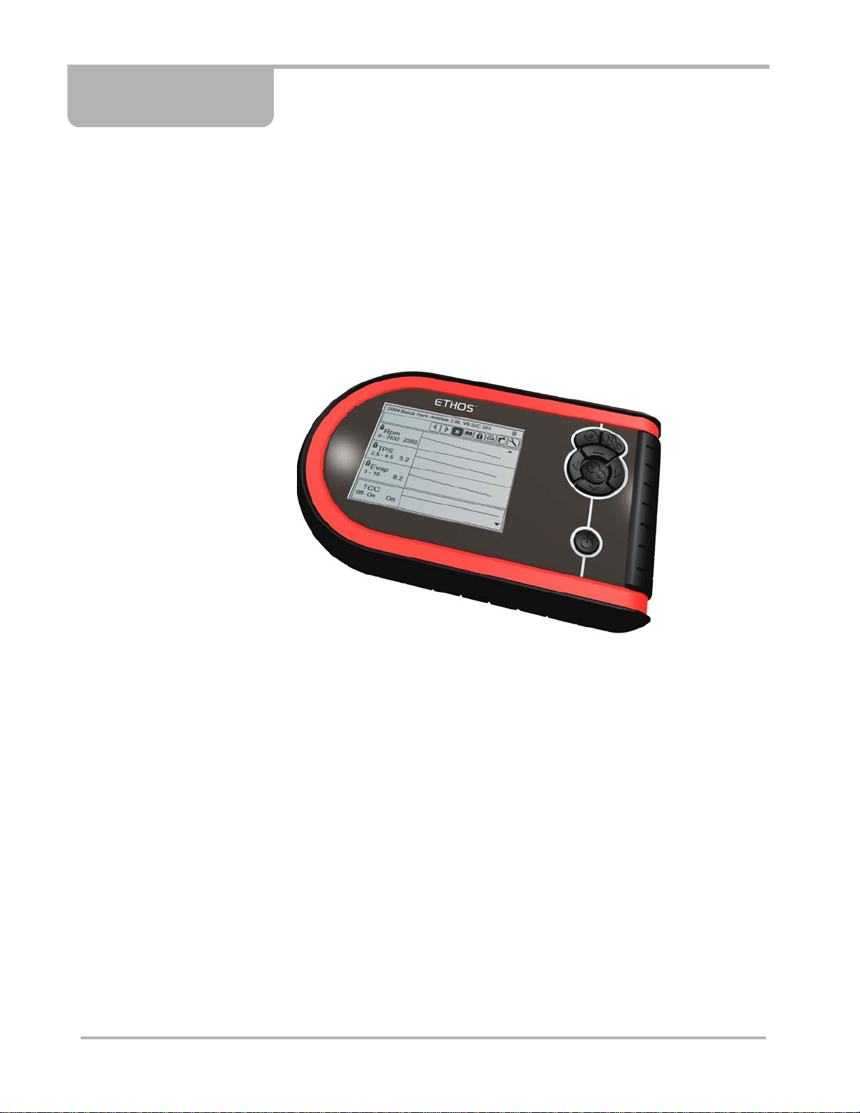
Chapter 2 Introduction
The ETHOS® (Figure 2-1) scan tool uses Vehicle Communication Software to provide
vehicle-specific diagnostic trouble codes (DTCs) and dat astrea m information for various
vehicle control systems such as engine, transmission, antilock brake system (ABS) and more.
Your scan tool can also graph live data parameters, recor d dat a, clear diagn ostic troubl e
codes (DTCs) from the vehicle electronic control module (ECM) memory, and reset the
vehicle malfunction indicator lamp (MIL).
Contact your sales representative for availability of software add-ons and upgrades.
Figure 2-1
2.1 Functional Description
This section illustrates external features, ports and connectors of the ETHOS®.
3
ETHOS® scan tool
Page 11
Introduction Functional Description
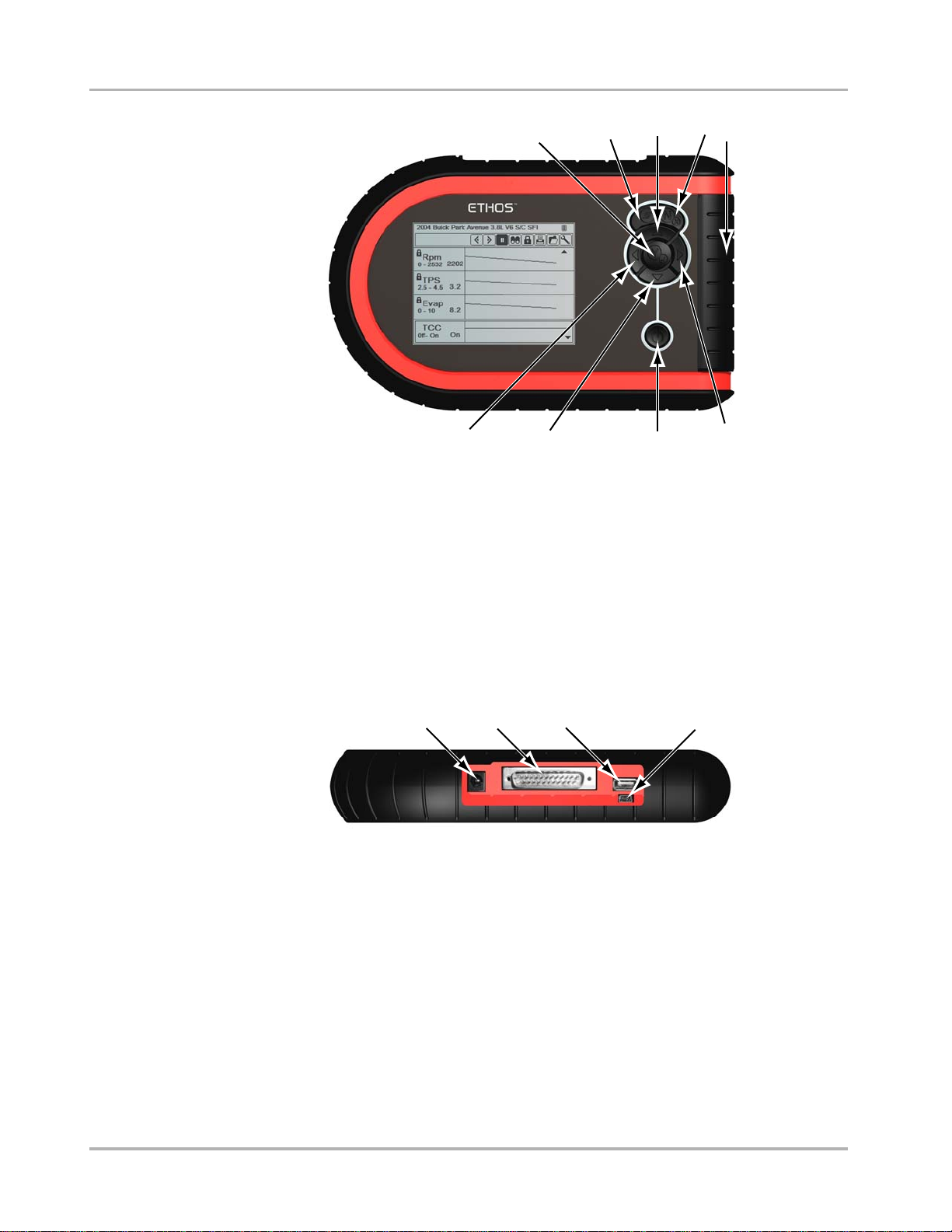
1— Y/a (accep t ) bu tton
2— S button
3— b (Up) button
4— N/x (back) button
5— CompactFlash
®
card slot, under endgrip
6— c (Right) button
7— Power button
8— d (Down) button
9— e (Left) button
1
9
8
2
Figure 2-2 E THOS® unit front view
3
7
4
5
6
1
1— DC power supply input
2— Data cable connector
3— USB port
4— Mini USB port
2
Figure 2-3
4
3
ETHOS® unit top view
4
Page 12
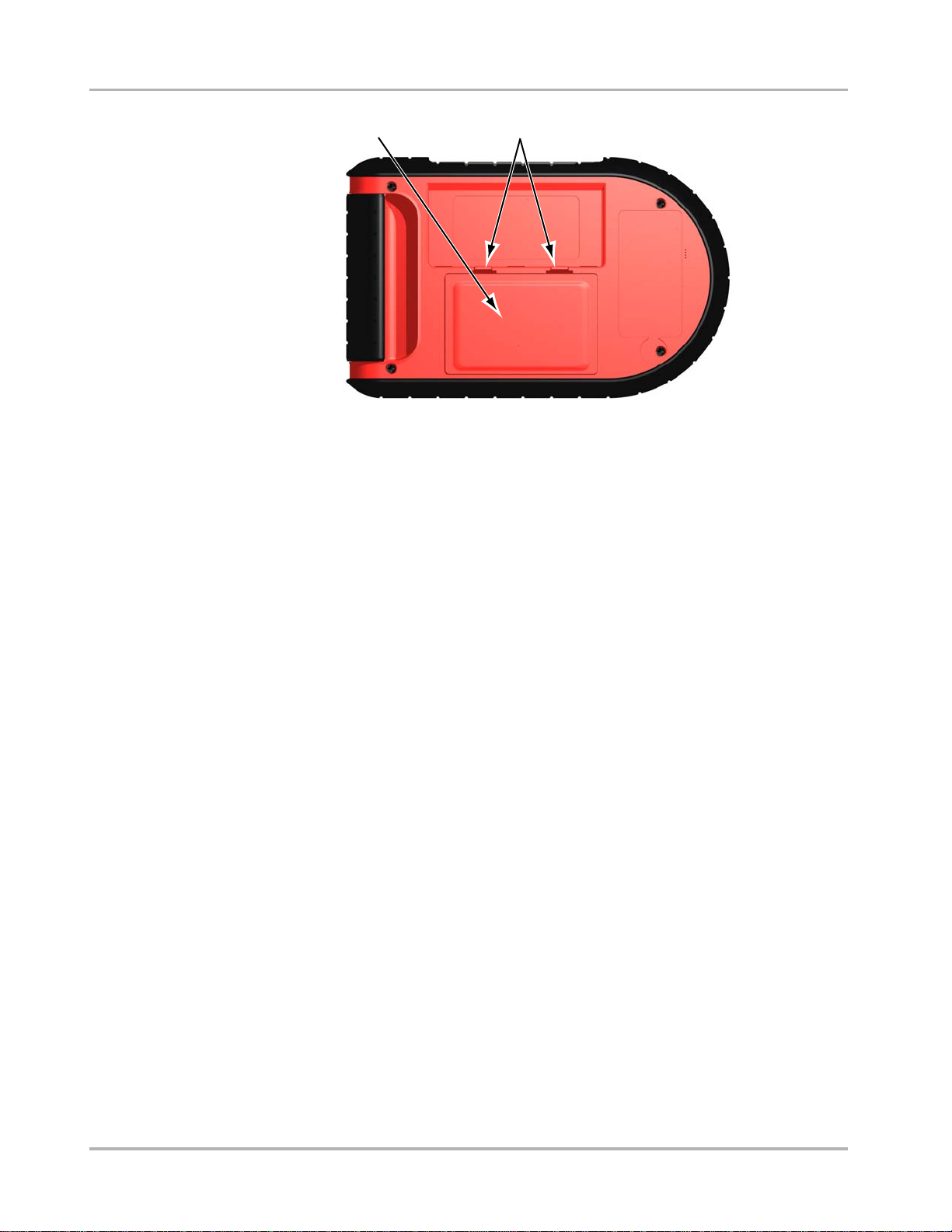
Introduction T echnical Specifications
1
Figure 2-4 ETHOS® unit back view
1— Battery cover
2— Locking tabs
2.2 T echnical S pecifications
2
Display:
Light Emitting Diode (LED) backlight monochrome screen
320 x 240 resolution
4.7 inch (119.38 mm) diagonal
Batteries:
(6) 1.5V AA
AC adapter:
Input: 100–240V, 47–63 Hz
Output: 15V DC
Dimensions:
Width:
9.05 inches
229.9 mm
Height:
5.70 inches
144.7 mm
Depth:
1.67 inches
42.3 mm
5
Page 13

Introduction Control Buttons
Weight:
Without batteries
1.42 lbs
643.5 g
Operating Temperature Range:
14 to 104°F
-10 to 40°C
Storage Temperature Range:
-4 to 149°F
-20 to 65°C
Data Buffer
240 data frames (values per parameter)
Communication Protocols
Your ETHOS scan tool supports the following OBD-II/EOBD communications protocols:
SAE J1850 (VPW)
SAE J1850 (PWM)
ISO 9141-2
ISO 14230-4 (KWP 2000)
ISO 15765-4 (CAN)
In addition, the optional vehicle communications software allows you to access “enhanced”
diagnostic information for specific vehicle manufacturers.
2.3 Control Buttons
The scan tool has the following control buttons (Figur e 2-2 on page 4):
• S (function)
• N/x (back)
• Y/a (accept)
• b (Up)
• d (Down)
• e (Left)
• c (Right)
• Power
2.3.1 S Button
The S button can be customized to perform different functions. See “S Button” on p age 33 for
additional information.
6
Page 14

Introduction Connections
2.3.2 N/x (Back) Button
The N/x button is used to do the following:
• To exit a menu or program.
• To close an open list and return to the previous menu.
• To answer “No” when a Yes or No choice is given.
• To return to the main menu.
2.3.3 Y/a (Accept) Button
The Y/a button is used to do the following:
• To select the item that you highlighted using the direction buttons.
• To answer “Yes” when a Yes or No choice is given.
2.3.4 Directional Buttons
The directional, or arrow, buttons move the cursor or highlight in their respective directions:
• Up (b)
• Down (d)
• Left (e)
• Right (c)
2.3.5 Power Button
The Power button powers up the tool, and turns it off. See “Powe ring On the Unit” on page 14
and “Powering Off the Unit” on p age 15 for details.
2.4 Connections
This scan tool uses the following connections (Figure 2-3 on page 4):
• DC power adapter input
• USB port
• Mini USB port
• Data cable connect or
• CompactFlash
®
(CF) card slot
7
Page 15

Introduction Power Supply
2.4.1 DC Power Input
The DC power input can be used to power the unit via an AC/DC power supply. For related
information, see the following sections:
• “AC/DC Power Supply” on page 9
• “Connecting the AC/DC Power Supply” on page 14
2.4.2 USB Port
This scan tool has a USB port for connecting to a printer.
2.4.3 Mini USB Port
The mini USB port on top of the unit is used for updating the internal software, and for
transferring saved files to a personal computer.
2.4.4 Data Cable Connector
The data cable connector is used to connect the scan tool to a ve hicle dat a link co nnector
(DLC) for testing.
For related information, see the following sections:
• “93L Data Cable” on page 10
• “Connecting to Ve hicle Power” on p age 12
2.4.5 CompactFlash® Card Slot
The CompactFlash® (CF) card slot, located under the handgrip, adds optional functiona lity to
the scan tool. The ETHOS unit does not require a CF card to operate. The CF card slot on the
scan tool is used for creating a backup file of the operating syste m and for accessin g cert ain
update functions.
2.5 Power Supply
This scan tool can receive power from three sources:
• Vehicle power
• Battery power
• AC/DC power supply
For related information, see “Vehicle Power” on page 9.
8
Page 16

Introduction Power Supply
2.5.1 Vehicle Power
Vehicle power is r equired for the scan to ol to proper ly communica te with the vehi cle dur ing
testing. The 93L Data Cable (EAC0093L01A) provides 1 2V power to the unit throu gh the
vehicle data link connector (DLC). The scan tool turns on automatically whene ver it is
connected to a DLC that provides power.
Certain vehicles do not provide vehicle power on the DLC. For these applications, a separate
cable adapter and power cable are needed to power the unit. Optional data cable adap ters are
available for a number of vehicle manufacturers. Contact your sales representative for
availability.
The power cable connects to a port on the cable adapter.
IMPORTANT:IMPORTANT:
Never connect the optional power cable or the AC/DC power supply to the DC po wer supply
input on top of the unit when the scan tool is communicating with the veh icle.
For related information, see “Connecting to Vehicle Power” on page 12.
2.5.2 Battery Power
This scan tool can receive power from six internal type AA batteries. Alkaline or rechargeable
nickel-metal hydride (NiMH) batteries must be used, Standard (lead/zinc) batteries do not
provide sufficient power and have a tendency to leak, which can damage th e scan tool .
Battery power should not be the primary source of power . Vehicle p ower should be the source
of power during testing. Use battery power to review saved files and for identifying a test
vehicle without connecting to the DLC.
For related information, see the following sections:
• “Installing the Batteries” on page 11
• “Replacing the Batteries” on page 39
• “Setup” on page 34
2.5.3 AC/DC Power Supply
The scan tool can be powered from a wall socket using the AC/DC power supply (Figure 2-5).
Figure 2-5
9
AC\DC power supply
Page 17

Introduction 93L Data Cable
For related information, see the following sections:
• “DC Power Input” on page 8
• “Connecting the AC/DC Power Supply” on page 14
2.6 93L Data Cable
An 93L Data Cable (Figure 2-6) is included with your scan tool. The data cable plugs directly
into the 16-pin data link connector (DLC) on OBD-II vehicles.
Figure 2-6
93L Data Cable
10
Page 18

Chapter 3 Getting Started
To get started using your ETHOS® scan tool:
1. Supply power to the tool.
2. Turn on the unit.
3.1 Supplying Power
There are three ways to supply power to this scan tool:
• Install batteries
• Connect to vehicle power
• Connect to an AC/DC power supply
For related information, see “Power Supply” on p age 8.
NOTE:
i T o con serve batteries, we r ecommend alwa ys powerin g the unit from vehicle power or from
the AC/DC power supply.
3.2 Installing the Batteries
The scan tool comes with six alkaline AA batteries. Rechargeable nickel -met al hyd ride
(NiMH) batteries may also be used. Do not use stan dard (l ead/zinc) batterie s as they do not
provide sufficient power to operate the scan tool, and ma y leak and dama ge your ETHOS®.
For related information, see the following sections:
• “Battery Power” on page 9
• “Replacing the Batteries” on page 39
IMPORTANT:IMPORTANT:
Your scan tool will not operate and may be damaged if the battery polarity is incorrect. Refer
to the diagrams on the battery slots for correct battery po larity.
z To install the batteries:
1. Depress the two locking tabs of the battery cover on the back of the scan tool (Figu re 2-4
on page 5).
2. Lift the cover off.
3. Observe correct polarity as shown by the diagrams on the battery slots (Figure 3-1), and
install the batteries.
11
Page 19

Getting Started Connecting to Vehicle Power
Figure 3-1 ETHOS® battery polarity
4. Replace the battery cover.
Note the following safety warnings when installing batteries.
WARNING
!
Risk of personal injury or harm.
• Always make sure the battery polarities (“+” and “–”) are correct when installing.
• Do not expose batteries to excessive heat.
• Use batteries from a reputable manufacturer only.
• When replacing batteries, always replace the co mplete set.
• Do not use different brands of batteries together.
• Do not try to recharge batteries that are not specifically designed to be r echarged.
• Do not allow children to install batteries unsupervised.
• Follow the battery manufacturer's instructions as to proper handling, storage, and
disposal of batteries.
Improper use of batteries can result in personal harm.
3.3 Connecting to V ehicle Power
The 93L Data Cable, included with your scan tool, p lugs directly into the d at a link co nnector
(DLC) on OBD-II/EOBD vehicles. For related information, see the following sections:
• “Data Cable Connector” on page 8
• “Vehi cle Power” on p age 9
• “Connecting to a V ehicle” on page 24
12
Page 20

Getting Started Connecting to Vehicle Power
z To connect to vehicle power:
1. Attach the connector saver to the data ca ble conne ctor on the top of the tool (Figure 3-2
on page 13), and secure it with the captive screws.
IMPORTANT:IMPORTANT:
After installing the connector saver, leave it attached to the unit when storing the scan tool.
Disconnect the data cable from the connector sa ver, but do not remove the connector saver
from the scan tool.
12 3
Figure 3-2
1— Ethos unit
2— Connector saver
3— 93L Data cable
2. Attach the 25-pin connector of the 93L Dat a Ca ble to the connector sa ver (Figu re 3-2).
Tighten the captive screws to e nsure a good conn ection.
3. Connect the 16-pin connector of the 93L Data Cable to the DLC of the test vehicle. See
the appropriate vehicle communication sof tware (VCS) manua l for vehi cle diagnostic
connector locations.
4. Turn the ignition on.
NOTE:
Data cable connections
i This scan tool can communicate with many non-OBD-II/EOBD vehicles, however, a data
cable adapter and other optional equipment may be nee ded to conn ect to the veh icle an d to
power the tool. Contact your sales representa tive for det ails. Refer to the applicab le vehicle
communication manual for connection and test procedures.
13
Page 21

Getting Started Connecting the AC/DC Power Supply
3.4 Connecting the AC/DC Power Supply
The AC/DC power supply (included) provides power from a wall socke t.
For related information, see the following sections:
• “DC Power Input” on page 8
• “AC/DC Power Supply” on page 9
z To connect an AC/DC power supply:
1. Plug the 2.5 mm end of the AC/DC power supply cord into the DC power adapter input on
the top of the tool.
2. Plug the other end of the power cord into an appropriate wall socket.
IMPORTANT:IMPORTANT:
Never connect the AC/DC power supply to the DC power supply input on top of the unit when
the scan tool is communicating with the vehicle.
3.5 Powering On the Unit
When power is supplied, you can power on your scan tool. For related infor mation, se e
“Powering Off the Unit” on page 15.
z To power on the scan tool:
• Press the Power button (Figure 2-2 on page 4).
The unit beeps and the main menu screen displays af ter a few seconds.
3.6 Selecting a Language
NOTE:
i This Selecting a Language section applies to units sold in North America only.
English is the default language selection in the ETHOS software. However, you can change
the language setting if desired.
z To change the language setting:
1. Select Tools from the menu.
2. Select Setup on the toolbar.
3. Select Language on the menu.
4. Select the desired language and press Y/a.
5. Press N/x to exit.
The language remains as selected af te r poweri ng down.
14
Page 22

Getting Started Powering Off the Unit
3.7 Powering Off the Unit
Use the Power button (Figure 2-2 on page 4) to turn the scan tool off.
z To power the unit off:
1. Navigate to a menu.
2. Press the Power button.
The Shut Down System dialog box displays (Figure 3-3).
Power OFF?
Press Y: Power OFF or N: to Continue.
Figure 3-3
3. Press Y/a to power down, or press N/x to cancel.
NOTE:
Sample shut down system message
i The scan tool does not power down when viewing data. Exit data and return to the menu
before attempting to shut off the scan tool.
3.8 Demonstration Programs
The Vehicle Com municatio n Sof tware ( VCS) contains programs to demonstrate many of the
scan tool test capabilities without actually connecting to a vehicle. A sample vehicle with mock
test results is provided to help you become familiar with menus and basic operations. These
simulated programs are available for a number of dif fer ent vehi cle manufacturer s.
z To open the OBD-II demonstration program:
1. Select Global OBDII from the main menu.
2. Press Y/a at the software confirmation screen.
3. Select OBD Training Mode.
4. Select Start Communication to start the program.
Y ou can select fr om any of the menus to see simulated dat a. The scan tool operates just a s it
would if connected to an actual vehicle.
Demonstration programs are available for a numbe r of different vehicle manufacturers when
optional VCS packages are installed on you r scan tool. A “Demonstration” sele ction appears
on the menu when available.
15
Page 23

Chapter 4 Navigation
The following sections describe screen layout, how to navigate the interface, and how to make
selections using screen menus and buttons. The various types of ET HOS® screen messages
are also explained in this section.
4.1 Screen Layout
Scan tool screens (Figure 4-1) typically include the following sections:
• The title bar—shows test and tool status.
• The toolbar—contains test controls.
• The main body—displays menus and test data.
1— Title bar
2— Toolbar
3— Main body
4.1.1 Title Bar
The title bar at the top of the screen, provides basic in formation a bout cu rrent tool operatin g
conditions. Title bar options vary depend ing upon vehicle make and model, wh at test is being
performed or what menu is selected. T itle ba r inform ation may include:
1
2
3
RPM
RPM 1411
TPS(%) 0
TPS(V) 0.00
O2 B1-S1(mV) 677
O2 B2-S1(mV) 482
O2 B1-S2(mV) 786
O2 B2-S2(mV) 790
INJ PW B1(mS) 13.0
INJ PW B2(mS) 13.6
Figure 4-1
Sample ETHOS screen
• The identification (ID) of the test vehicle
• The name of the active menu or database
• The complete name of the highlighted abbreviated p ar ameter name in graph m ode
• A power source indicator
• A vehicle communication indicator
16
Page 24

Navigation Screen Layout
Definitions of title bar icons are shown in Table 4-1.
Table 4-1
Power source
Title bar icon definitions
TYPE ICON DEFINITION
Indicates power is being supplied by
the internal batteries
Indicates the internal batteries are
weak and need replacement
Indicates power is being supplied by
the AC/DC power supply
Indicates power is being supplied by
the vehicle
Depending upon what is being displayed in the main body of the screen, either the vehicle ID
or the active menu is shown at the left side of the title bar.
An icon at the far right side of the title bar indicates whether the tool is being power ed by the
internal batteries, the test vehicle, or the AC\DC power supply.
A vehicle communication icon displays to the left of the power source indicator whenever the
scan tool is actively communicating with a test vehicle.
Four LED indicators appears to the left of th e vehicle communications icon during certain test s
on some vehicles. The LEDs cycle on and off to show cert a in engin e oper ating cond itions
based on parameter values. Default settings for the LEDs va ry by manufacturer.
4.1.2 Toolbar
The toolbar , located under the title bar, contains a number of selectable buttons that contr ol
tool functions. Toolbar button operations are shown in Table 4-2, see “Using Tools” on
page 33 for details.
Vehicle
communication
Indicates an active communication link
with the vehicle ECM
Table 4-2 Data toolbar buttons (part 1 of 2)
BUTTON ICON FUNCTION
Pause
Cursor
Play
Previous Frame
Indicates live data from the vehicle is
being displayed
Moves forward ten frames at a time
when viewing recorded or paused data
Indicates the data being displayed is
paused when reviewing a movie.
Moves back one frame when viewing
recorded or paused data
17
Page 25

Navigation Making Selections
Table 4-2 Data toolbar buttons (part 2 of 2)
BUTTON ICON FUNCTION
Next Frame
Record
Custom Data List
View
Lock/Unlock
Print
Save
Tools Opens the tools menu
Moves forward one frame when
viewing recorded or paused data
When collecting data, indicates the
data being displayed is paused and not
being updated
Lets you selects which parameters to
display from the list
Switches between text and graph
display modes
Locks or unlocks the highlighted
parameter
Sends the current datastream
information to a printer
Saves the current datastream
information to tool memory
4.1.3 Main Body
The main body of the screen is the lower portion, which displays either a menu of available
tests or data from the vehicle .
4.2 Making Selections
Use the following instructions to navigate the interface and make selections.
NOTE:
i The title bar contains read-only information.
z To navigate the Toolbar:
• Press the left (e) and right (c) buttons.
z To navigate the main body:
• Press the up (b) and down (d) buttons.
18
Page 26

Navigation Screen Messages
z To make selections:
1. Highlight a button or menu option.
2. Press Y/a to confirm the selection.
NOTE:
i Menus that only list one item require a press of the Y/a button to advance.
4.3 Screen Messages
There are four types of on-screen messages:
• Loading and connecting
• Confirmations
• Warnings
• Errors
4.3.1 Loading and Connecting Messages
Loading and connecting messages display when this scan tool is per forming an in ternal
operation, such as loading a database, initiating a test, or establishin g communications with
the vehicle. The message automatically clears once th e intern al oper ation is complete.
4.3.2 Confirmation Messages
Confirmation messages inform you when you are about to perform an a ction that can not be
reversed or when an action that requires your confirmation to co ntinue has b een initiated.
When a user-response is not required, the messa ge disp lays briefly befor e disa ppear ing.
4.3.3 Warning Messages
Warning messages inform you when completing the selected action may result in an
irreversible change or loss of data.
4.3.4 Error Messages
Error messages inform you when a system or procedural error has occurre d.
Examples of possible errors include:
• A cable is disconnected.
• A peripheral, such as a printer is powered off.
19
Page 27

Chapter 5 Operations
This section explains general ETHOS® scan tool operations and offers instructions for
customizing certain functions. The following is an outline of basic scan tool operations for
testing a vehicle.
NOTE:
i The sequence of steps and the menu selections may vary depending upon the make o r model
of the test vehicle. See the appropriate Vehicle Communication Software Manual for detailed
procedures.
1. Select from the Main Menu—Select the appropriate vehicle communication software
(VCS) for the manufacturer of the test vehicle. See “Selecting fr om th e Main Menu” on
page 21.
2. Identify the vehicle—Identify the test vehicle to the scan tool by entering VIN characters
and answering questions. See the appropriate Vehicle Communication Software Manua l
for instructions.
3. Select the system—Enter the system to be tested (engine, transmission, ABS, etc.). See
the appropriate V ehicle Comm unication Sof twar e Manual fo r instructio ns.
4. Connect the ETHOS® unit to the vehicle—Follow the on-screen connection
instructions to connect to the vehicle. See the appropriate Vehicle Communication
Software Manual for additional information.
5. Select the required test from the vehicle menu—Select the appropriate test for the
vehicle you have identified. See “Selecting from the V ehicle Menu” o n p age 25.
Select the Vehicle Communication Software
Identify the Vehicle
Select a System
Connect to the Vehicle
Select From the Vehicle Menu
Codes
Menu
Figure 5-1
Data
Display
Basic ETHOS® operations
Generic
Functions
20
Page 28

Operations Selecting from the Main Menu
5.1 Selecting from the Main Menu
When the scan tool is first powered up, the main menu displays. Use the menu selections to
load the correct software dat abase for the test vehi cle (Fig ure 5-2).
Selections vary by market and may include:
• Global OBDII—use to generically test any vehicle that is OBD-II compliant.
• EOBD—use to generically test any vehicle that is EOBD compliant.
• US Domestic Vehicles—use to test vehicles produced by US manufacturers.
• Asian Vehicles—u se to test vehicles produced by Japanese and Kor ean manufacturers.
• European Vehicles—use to test vehicles produced by European manufacturer s
Last Vehicle
Previous Vehicles and Data
Global OBDII
US Domestic Vehicles
Asian Vehicles
European Vehicles
Tools
Figure 5-2
The software selection screen also offers th ese options:
Sample ETHOS® unit main menu
• Last Vehicle—reset s the ID to the last vehicle tested. See “Main Menu Identification
Options” on page 22 for details.
• Previous Vehicles and Data—lets you quickly set the ID of any of the last 20 vehicles
previously tested. This selection is also used to access data files that you saved in tool
memory. See “Main Menu Identification Options” on page 22 for details.
• Tools—opens the T oo ls menu. Se e “Using Tools” on p age 33 for details.
z To Select the VCS
1. From the main menu, select the VCS for the vehicle.
When US Domestic Vehicles, Asian Vehicles, or European Vehicles is selected, a
manufacturer menu displays, select from the menu to continu e.
The software loads, then a confirmation screen displa ys.
2. Press Y/a to continue.
3. Select from the submenus as necessary.
5.2 Identifying the V ehicle
After you select the VCS for the test vehicle, you are re ady to identify the vehicle.
21
Page 29

Operations Identifying the Vehicle
NOTE:
i The identification procedure varies by manufacturer. See the appropriate Vehicle
Communication Software Manual for details.
z To identify a vehicle:
1. From the Software Confirmation screen, press Y/a.
The initial vehicle identification (ID) process begins (Figure 5-3).
Mercedes
Select 10th VIN Character
5 - 2005
4 - 2004
3 - 2003
2 - 2002
1 - 2001
Y - 2000
X - 1999
W - 1998
Figure 5-3
Sample Vehicle ID screen
2. Select the requested VIN characters, and press Y/a or N\x to answer the on-screen
questions as necessary.
A Current Vehicle Identification co nfirmatio n message d isplays when all of the ID
information has been entered.
3. Press Y/a to continue.
5.2.1 Main Menu Identification Options
The main menu offers two options fo r q uic kly i dent ifyi ng t he te st v ehi cle :
• Last Vehicle
• Previous Vehicles an d Dat a
Select Last Vehicle to r euse the id entification info rmation of th e last vehicle th at you tested
(Figure 5-2 on page 21).
z To select the last vehicle tested
1. From the main menu, select Last Vehicle.
The vehicle identification confirmation screen for the last vehicle tested displays.
2. Press Y/a.
The menu for the last vehicle tested displays.
Selecting Previous V e hicles and Data lets you select from the vehicle identifications and
data in tool memory (Figure 5-4).
22
Page 30

Operations Selecting a System
Previous Vehicles and Data
DeleteRestoreLast 20
2004 (10th VIN = 4) S80 2.3L 5CYL TURBO ...
2002 210 (E-SERIES) 210.065 (E-SERIES) ...
2004 HONDA CIVI 1.6L D16V
2000 HONDA S200 2.0L F20C
2001 (10th VIN = 1) NEW BEETLE 1.6 MPI ...
1999 5-SERIES [E39] 2.8L 24V MPI CAT =...
2002 (11th VIN Character = 2) FOCU 1.4L ...
2000 TOYOTA RAV4 1.8L 1ZZ
Figure 5-4 Sample Previous Vehicles and Data list
z To select from the previous vehicles and data list
1. Select Previous Vehicles and Data from the menu.
A list of the last 20 vehicles tested displays in the main body of the screen (F igure 5-4).
The Restore Data and Delete Data selections on the too lbar o pen a l ist of files th at have
been saved to tool memory.
2. Select Restore Data, or Delete Data to o pen a list of save d files (Figure 5-5).
Restore
DeleteRestoreLast 20
09:09:2008 08:17 000000001
2005 (10th VIN = 4) S80 2.3L 5 ...
09:09:2008 09:13 000000002
2002 210 (E-SERIES) 210.065 ...
09:09:2008 11:35 000000003
2004 5-SERIES [E39] 2.8L 24V ...
09:09:2008 14:12 000000003
2000 (11th VIN Character = 2) FOCU 1.4L
Figure 5-5
Sample Restore Data list
File names include the vehicle ID, date, and time.
a. If a selection is made from Restore Data or Delete Data, the movie file opens, or is
erased. A confirmation message must be accepted before files are deleted.
b. If a selection is made from Last 20, a vehicle ID confirmation screen displays after the
software loads. Verify the ID.
3. Press Y/a to continue.
A connection message displays.
4. Connect the data cable to the vehicle, then press Y/a.
The menu for the last system tested on the selected vehicle displays.
5.3 Selecting a System
You must select the vehicle control system you wish to test (Figure 5-6).
23
Page 31

Operations Connecting to a Vehicle
... FOCUS 1.6L DURATEC = U
System List (if Fitted):
Powertrain Control Module
Powertrain Related Systems
ABS Systems
Safety Systems
Security Systems
Undercar Related Systems
Information Systems
Comfort Control Systems
Figure 5-6 Sample sys tem s electi on s cre en
System availability varies by make, model, and year, see the appropriate vehicle
communication software manual for det ails on selecting a system.
5.4 Connecting to a V ehicle
Connection instructions prompt you to connect the scan tool to a vehicle data link conne ctor
(DLC) for testing (Figure 5-7). See the appropriate vehicle communication software manual
for details on connecting to a vehicle.
****ETHOS****
Connect: 93L Cable.
Location: Under left side of dash.
!
Press Y: Continue
Figure 5-7
Sample connection instruction screen
Vehicle power is require d for prop er scan tool to veh icle co mmunication during te sting. The
scan tool receives 12V power through the 93L Dat a Cable when conn ected to the vehicle
DLC. The scan tool turns on automatically when connected to a DLC tha t pro vides power.
Certain vehicles do not provide vehicle power on the DLC. For these applications, a separate
cable adapter and power cable are needed to p ower th e unit, con t act your sales
representative for availability. Optional data cable adapters are available for a number of
vehicle manufacturers. The power cable connects to a por t on the cable a dapter.
IMPORTANT:IMPORTANT:
Never connect the optional power cable or AC/DC power supply to the DC power supply input
on top of the unit when the scan tool is communicating with the vehicle.
If vehicle power is not available from the DLC, a “No power from vehicle” message may
display when the tool is powered up. Should this happen, verify that power is available on the
DLC, or connect the optional auxiliary power cables before continuing.
24
Page 32

Operations Selecting from the Vehicle Menu
5.5 Selecting from the V ehicle Menu
Depending on the make and model, a number of options may be availabl e (Figure 5-8).
... 2.5L 24V MPI CAT = 256S5
Main Menu
Codes Only
Data Only
Functional Tests
Service Reset
Stop Communication
Vehicle menu o ptions vary an d may in clude th e following:
• Codes Menu—displays a submenu of choices for viewing and clearing diagnostic trouble
code (DTC) records.
• Codes Only—displays a list of DTCs stored in the selected control module.
• Service Codes—displays a list of DTCs stored in the selected control module.
• Data Display—displays data parame ter information from the selected co ntrol module.
• Data Only—displays data p aram eter information from th e selected control mod ule.
• Generic Functions—displays a submenu of OBD-II tests availab le for th e vehicle.
• Functional Tests—displays a submenu of tests available for the vehi cle.
• Service Reset—displays a submenu of options for resetting service reminder lam p s.
• Stop Communication—electronically disconnects the scan too l from the vehi cle.
5.5.1 Codes Menu
Selecting Codes Menu opens a submenu (Figur e 5-9 on page 26) that typically includes:
• Trouble Codes—displa ys a subme nu of choices fo r viewing DTC reco rds.
• Clear Codes—erases DTC records from the active electronic control module (ECM) on
the vehicle.
• Freeze Frame/Failure Records—displays OBD-II required dat a fr om the vehicle ECM.
• DTC Status—displays ECM records for the specified tro uble code .
Figure 5-8
Sample vehicle menu
Selection names and the number of selections will vary by make, model and year. Refer to the
appropriate V ehicle Communication So f tware M anual for de t ails.
25
Page 33

Operations Selecting from the Vehicle Menu
... 2004 3.8L V6 ...
Codes Menu
Trouble Codes
Clear Codes
Freeze Frame/Failure Records
DTC Status
Figure 5-9 Sample codes submenu
5.5.2 Data Display
Select Data Display to view live datastream parameters from the vehicle ECM (Figure 5-10).
RPM
1
RPM 1411
TPS(%) 0
TPS(V) 0.00
O2 B1-S1(mV) 677
2
O2 B2-S1(mV) 482
O2 B1-S2(mV) 786
O2 B2-S2(mV) 790
INJ PW B1(mS) 13.0
INJ PW B2(mS) 13.6
Figure 5-10
Sample data display screen
1— Toolbar
2— Main body
In data display mode the screen has an upper too lbar an d a main body.
Toolbar
The buttons on the toolbar operate as shown in Table 4-2 on page 17 while viewing data.
Refer to “Using Tools” on page 33 for button function details.
Main Body
During data display, The main body of the display is horizontally divided into two frame s
(Figure 5-1 1). Three parameters can be fixed at the top of the list, so they do not change as
you scroll through the parameter list in the lower fra me. Use the Lock/Unlock button on the
upper toolbar to select which parameters are fixed (see “L ocking Param eters” on p a ge 30).
26
Page 34

Operations Selecting from the Vehicle Menu
ST TRIM-1(%)
O2 B1-S1(mV) 109
1
2
INJ PW B1(mS) 19.3
ST TRIM-1(%) -1
O2 B2-S1(mV) 143
O2 B1-S2(mV) 781
O2 B2-S2(mV) 777
INJ PW B1(mS) 19.3
INJ PW B2(mS) 14.0
ST TRIM-1(%) -1
Figure 5-11 Sample data display screen
1— Upper frame (locked parameters)
2— Lower frame (unlocked parameters)
Pausing Data Collection
Y ou may “p ause” the collection of data from the vehicle control modu le. When data is paused,
the previous 230 frames of vehicle data, before Y/a was pressed, are stored in tool memory,
and are available for review.
z To pause data collection:
1. While viewing live data, select Pause.
The toolbar icon changes to Record, the Cursor, Previous Frame, and Next Frame
buttons display, and a frame counter displays below the toolbar (Figure 5-12).
TPS(V)
RPM 1963
TPS(%) 0
TPS(V) 0.00
O2 B1-S1(mV) 113
O2 B2-S1(mV) 95
O2 B1-S2(mV) 781
O2 B2-S2(mV) 777
INJ PW B1(mS) 13.7
INJ PW B2(mS) 13.8
1— Cursor button
2— Previous Frame button
3— Next Frame button
4— Record button
5— Frame counter (total number of frames)
6— Frame counter (current frame)
1 3
2
Figure 5-12
30/230
4
5
6
Sample paused frame of data
27
Page 35

Operations Selecting from the Vehicle Menu
2. Scroll to review the data in the fra me.
3. T o switch frames, Highlight Previous Frame or Next Fra me, then press Y/a. Each button
push moves one frame in the selected direction.
z To resume collecting data:
• Select Record.
The display changes to live data and the Pause icon is shown on the toolba r.
The S button can be set to perform the Pause/Play function. See “ S Button” on page 33 for
additional information.
Using the Cursor Button
The Cursor button only displays while data collection paused. When the button is highlighted,
each press of the Y/a button advances the data 10 frames. A vertical line indicates the cursor
position when viewing data graphs (Figure 5-13).
RPM
RPM
1963
755-3274
TPS 1(V)
0.00
0.00-3.55
TPS 1(%)
0
0-98
TPS 2(V)
0.00
0.00-3.55
Figure 5-13
30 / 230
Sample cursor indicator
Customizing the Data List
The Custom Data List button lets you determi ne which parameters display from the list. Not
including unnecessary parameters can speed up the screen update r ate.
z To make a custom data list:
1. Select Custom Data List on the toolbar.
The data selection screen displays (Figure 5-14). Check marks indicate which
parameters are selected for display. A second smaller check box indicates a parameter
that is locked.
28
Page 36

Operations Selecting from the Vehicle Menu
RPM
RPM
TPS(%)
TPS(V)
O2 B1-S1(mV)
O2 B2-S1(mV)
O2 B1-S2(mV)
O2 B2-S2(mV)
INJ PW B1(mS)
INJ PW B2(mS)
Figure 5-14 Sample dat a selection screen
2. Highlight a button on the Custom Data List toolbar.
Use the left (e) and right (c) arrows to move between buttons.
Button Description
Select/Deselect, use to mark individual
parameters to hide or display.
Select All/Deselect All, use to mark all
parameters in the list to hide or display. Any
locked parameters cannot be hidden.
3. With Select All/Deselect All highlighted, press Y/a.
Now, all the p a rameters change to the same co ndition.
4. With Select/Deselect highlighted, use the up (b) and down (d) arrows to navigate to the
targeted parameters.
5. Press Y/a to switch the condition of a highlighted parameter.
6. Once you custom data list is configured, press N/x to return to the data display.
Changing Screen Views
The View button switches the screen view between Text view and Graph view . When Graph
view is selected, the data graphs of four p ara me ters display in th e main body of the scre en
(Figure 5-15). Use the up (b) and down (d) buttons to scroll and view other parameters.
29
Page 37

Operations Selecting from the Vehicle Menu
RPM
RPM
3001
755-3238
TPS(%)
0
0-98
TPS(V)
0.00
0.00-3.55
02 B1S1(m
894
52-911
Figure 5-15 Sample Graph view screen
Any previously set conditions, such as held data or locked lines of data, remain in effect when
the screen view is changed.
z To change the screen view:
• Select the View button.
From Text view the screen changes to a Graph view (Figure 5-15). From Graph view the
display changes to Text vi ew.
Locking Parameters
Use the Lock/Unlock button to lock selected lines of the data in place and prevent them from
scrolling, or to release previously locked lines of dat a. Up to three lines of dat a may be held at
a time, the bottom line of the display cannot be locked. This feature allows you to position
related parameters together , making it easier to monitor their values and spot inconsistencies.
When viewing in text mode, locked data lines move to the uppe r frame on the main body of the
display screen.
When viewing in graph mode, a lock icon appears alongside the parameter name to indicate
it is locked.
RPM
RPM
1963
755-3274
RPM
1963
755-3274
TPS(%)
0
0-98
TPS(V)
0.00
0.00-3.55
Figure 5-16
Sample locked graph
30
Page 38

Operations Selecting from the Vehicle Menu
z To lock parameters:
1. Highlight the parameter to be locked.
NOTE:
i If three parameters are locked, one of them must first be unlocked before anoth er p arameter
can be locked.
2. Select Lock/Unlock.
A lock icon displays next to the parameter name, an d the parameter displays in the upper
frame on the screen.
z To unlock parameters:
1. Highlight the parameter to be unlocked.
2. Select Lock/Unlock.
The lock icon disappears and the parameter ca n be scrolle d as before .
Saving
The Save button is used to record movies of vehicle datastream values into tool memory.
Saving helps when trying to isolate an intermi ttent problem or verify a repair dur ing a road test.
Saved files also provide documentation that helps you explain driveability problems to your
customers.
A number of data movies can be stored, which can later be opened by selecting the Tool
button, or by selecting T ools on the main menu. Each movie contains up to 240 frames of data.
z To save a movie:
• Select Save.
A save movie dialog box displays while data is being saved (Figure 5-17). The movie is
saved when the message box disappears.
****ETHOS****
Saving the Movie.
Figure 5-17
The S button can be programmed to perform the Save Screen or Save Movie function. See “S
Button” on page 33 for details.
Saved files can also be downloaded from the scan tool to a persona l computer through the
Mini USB port.
Sample Save Movie dialog box
31
Page 39

Operations Selecting from the Vehicle Menu
Printing
The Print button lets you print the displayed scr een.
z To print data:
1. Verify that your printer and scan tool are set up properly for printing.
2. Select a Print from the toolbar.
The current screen is sent to the printer.
A screen print includes the vehicle identification, the date and time. Graphed dat a must be
printed one screen at a time.
The S button can be programmed to perform print functions, Prin t Screen or Print Page. See
“S Button” on page 33 for details.
Tools
The Tools button is a shortcut, it is the same as selecting T ools from the ETHOS main menu.
See “Using Tools” on page 33 for details.
5.5.3 Generic Functions
Select Generic Functi ons from a VIN-specific menu and a submenu o f OBD-II tests displays
(Figure 5-18).
Menu choices may include:
• Freeze Frame—displays data stored in ECM memory.
• Readiness Monitors—displays the status of moni tors required for OBD-II compliance.
• Mode 6 Non-Cont—displays the status of monitors that ar e not req uired for OBD- II
compliance.
• Mode 9 Calib. ID—displays ECM calibration information for the test vehicle.
• Mode 9 (CVN)—displays the calibration verification number for the test vehicle.
• Mode 9 (VIN)—displays the vehicle identification number of the test vehicle.
... Q45 SEDAN 4.1L V8 MFI (VH41DE)
Freeze Frame
Readiness Monitors
Mode 6 Non-Cont
Mode 9 Calib. ID
Mode 9 (CVN)
Mode 9 (VIN)
Figure 5-18
Sample Generic Functions menu
32
Page 40

Operations Using Tools
5.6 Using T ools
The Tools button provides access to system information and various system controls. The
tools options are discussed in the following sections:
• “S Button” on page 33
• “Units” on page 34
• “Setup” on page 34
• “Sys (System Information)” on page 35
• “Update from CF” on page 36
Tools Menu
SetupUnitsS
Brightness
Print Screen
Freeze/Run Toggle
Print Page
Save Screen
Save Movie
Show S Menu
i
Sys
5.6.1 S Button
Selecting S button allows you to change tool settings, which lets you perform the set function
with a single button push. Possible function assignments include:
• Brightness—adjusts the backlighting on the display.
• Print Page—sends the current page, which includes the complete list of data p arameters,
to the printer.
• Print Screen—prints only the data currently being displaye d on th e screen.
• Save Movie—works like the Save button in the data display toolbar. See “Saving” on
page 31 for details.
• Save Screen—saves data displayed on the curren t screen to to ol memory.
• Show S Menu Shortcut s —o pens this menu so yo u can quickly reconfigur e the button
setting.
• T oggle Re cord/Pa use—works as the Pa use/Record bu tton when viewing d at a. See
“Pausing Data Collection” on page 27 for details.
z To assign a funct ion to the S button:
1. Select T ools > S.
2. Select a function from the list (Figure 5-19).
The selection is indicated by a check mark.
3. Press N/x to return to the main menu.
Figure 5-19
Sample Tools menu
33
Page 41

Operations Using Tools
5.6.2 Units
Select Units to choose between US customary or metr ic unit s o f measure for cert ain d at a
parameters.
Table 5-1
SETTING DEFAULT OPTION
Temperature degrees Celsius (°C) degrees Fahrenheit (°F)
Air Pressure
(including manifold
pressure)
Pressures
(all others)
Vehicle Speed kilometers per hour (kph) miles per hour (mph)
z To change units:
1. Select Units.
A list of choices displays with the current settings shown in brackets (Figure 5-20).
Units of measurement—defaults and options
kilopascals (kPa) inches of mercury (“Hg)
kilopascals (kPa) pounds per square inch (psi)
Tools Menu
SetupUnitsS
Temperature
Air Pressure
Pressure (all others)
Vehicle Speed
i
[°F]
[°C]
Sys
[[°F]]
[kPa]
[kPa]
[KPH]
2. Highlight a menu item and press Y/a.
A selection menu opens.
3. Highlight the desired setting and press Y/a.
4. Press N/x to return to the main menu.
5.6.3 Setup
The Setup menu includes the following options:
• Printer—configures the scan tool to communicate with a printer through the USB port.
• Time Zone—sets the internal clock.
• Daylight Saving—modifies the internal clock for daylight savings time.
• Battery T ype —sets low battery warning message threshold for disposable or
rechargeable batteries.
• Brightness—opens a widow for adjusting the backlighting on the display screen.
Figure 5-20
34
Sample Units menu
Page 42

Operations Using Tools
• T ext Theme—switch es the appear ance of th e disp lay betwee n a Black on White and
White on Black format.
• DGA Port—Configures the scan tool to interface with a digital gas analyzer (DGA) on
units sold in some European markets.
• Language—changes the displayed language between English a nd Sp anish on units sold
in North America only, see “Selecting a Language” on page 14.
NOTE:
i This scan tool supports printing to PCL 3 (Printer Command Language Level 3) printe rs,
which supports some (color and black & white) printers. Check the manual for, or contact the
manufacturer of, your printer to see if it supports the PCL 3 standard.
z To change setup:
1. Highlight a menu item and press Y/a.
A submenu displays.
2. Highlight a menu item and press Y/a.
3. Press N/x to return to the main menu.
5.6.4 Sys (System Information)
The Sys selection lets you view your scan tool configuration infor mation (Figu re 5-21).
Tools Menu
ETHOS
Copyright 2008 Snap-on Incorporated. All Rights Reserved.
ETHOS
Patents US B15,442,170; AU 630,261; US 6,693,367; Patents Pending
09/09/2008 08:40
Bundle 8.4 Version 1.5.0.4883
RUNTIME 4.2.0.1
Serial Number:
E65F 0102 230C 15EF 1D04 0651
Figure 5-21
z To display system information:
1. Select Sys. The System Information displays.
2. Scroll Down (d) to view all of the information.
3. Press N/x to return to the main menu.
SetupUnitsS
TM
is a trademark of Snap-on Incorporated.
Sample system information screen
i
Sys
5.6.5 Connect-to-PC
The Connect-to-PC selection is used to transfer saved data files back and forth from the scan
tool and a personal computer (PC). Select Connect-to-PC and conn ection instru ctions
display on the screen.
35
Page 43

Operations Recording and Viewing Mov ies
5.6.6 Backup to CF
Select Backup to CF to save a backup copy of the ETHOS® programming and saved data to
a CompactFlash® (CF) card. Follow the screen instructions to cre ate a backup CF. See
“Making a Backup CompactFlash® (CF) Card” on p age 41for additional information.
5.6.7 Update from CF
Select Update from CF to restore the ETHOS® programming from a CF card. See “Restoring
from a CompactFlash® (CF) Card” on pa ge 41 for additional information.
5.7 Recording and Viewing Movies
Select Save while viewing live data to record a movie of vehicle data and store it in internal
memory (see “Saving” on page 31). These movies can be opened and reviewed from the
main menu.
z To review a movie:
1. Select Previous Vehicles and Data from the menu.
2. Select Saved Data on the toolbar.
3. Select a movie.
The movie opens and plays in real time. The Play button changes to the Pause button at
the end of the movie.
Movie reviewing tips:
• The Pause/Play an d View toolbar buttons are active while a movie is playing, so you can
stop the movie or switch to graph view at any time.
• The Previous Frame and Next Frame bu ttons are active if the dat a is p aused .
• The Print button is also active when viewing held data.
5.8 Service Menu
The Service Menu is used to perform tool maintenance and rep air operations, such as update
or restore the system software. The menu ope ns with a special st artup se quence. Th e
following selections display on the Service Menu:
• Disk Utilities
• ETHOS
• PC–LINK
Unless you are specifically instructed to do so and have precise instructions, do not attempt
to use the service menu items.
36
Page 44

Operations Service Menu
IMPORTANT:IMPORTANT:
Improper use of Service Menu items can corrupt the inte rnal file structure and render the scan
tool inoperative.
z To open the Service Menu:
1. Simultaneously hold down the Y/a and N/x buttons.
2. Press the Power button to open the Service Menu.
The Service menu displays.
IMPORTANT:IMPORTANT:
Do not attempt to open, view , or alter any of the files in any of the folders. These are sof tware
operating files and any changes will hamper tool functionality.
37
Page 45

Chapter 6 Maintenance
This section covers the following maintenance issues:
• Cleaning and damage inspection
• Display window replacement
• Replacing the batteries
• Storage tips
• Making a Backup CompactFlash® (CF) Card
• Updating from a CompactFlash® (CF) Card
6.1 Cleaning and Damage Inspection
When using this scan tool, make sure to do the following:
• Before and after each use, check the housing, wiring, an d connectors for dir t and
damage.
• At the end of each working day, clean the housing, wiring, and connectors with a slightly
damp cloth.
6.2 Display Window Replacement
Use the optional Display Window Kit to replace the hard plastic faceplate of the Ethos unit.
Thoroughly clean the scan tool first, and work carefully to keep dirt o ut of the un it during
window replacement.
z To install the Display Window Kit:
1. Lift up the back edge of the endgrip, then roll the hand grip off of the unit.
2. Insert a small screwdriver under the edge of the window at one of the pry slot s
(Figure 6-1).
38
Page 46

Maintenance Replacing the Batteries
1
2
1
2
1
Figure 6-1 Display window replacement.
1— Lock tab
2— Pry slot
3. Apply just enough pressure with the screwdriver to keep the windo w free as you pull back
the three lock tabs one at a time.
4. Tilt the window up to clear the buttons, then slide the window t a bs out o f the slot s on th e
unit (Figure 6-2).
Figure 6-2
5. Fit the new window onto the unit (Figure 6-2).
6. Lightly push down the edge of the window to engage the lock tabs.
7. Fit the endgrip.
6.3 Replacing the Batteries
When replacing the scan tool batteries, use Alkaline or rechargeable nickel-metal hydride
(NiMH) type AA batteries only. Do not use standard (lead/zinc) batteries as they do not
provide sufficient power to operate the scan tool, and ma y leak and dama ge your ETHOS®.
Use the following procedure when replacing batteries in your scan tool.
39
Replacement window
Page 47

Maintenance Storage Tips
z To replace the batteries:
1. Depress the two battery cover lock tabs and lift off the b attery cover (Figur e 6-3).
1
Figure 6-3
1— Battery cover
2— Lock tabs
2. Remove the old batteries.
3. Observing proper polarity (shown on the battery slots), inst all six ne w AA batteries.
IMPORTANT:IMPORTANT:
Your scan tool can be damaged if the battery polarity is incorrect. Refe r to the dia gram in the
battery compartment on the rear of the tool for correct battery polarity.
2
Battery cover lock tabs
4. Replace the battery cover.
NOTE:
i If installing rechargeable batteries, be sure to reset the battery type on the Tools Setup menu
(see “Setup” on page 34). This helps prolong the life of the batteries, and notifies you when it
is time to recharge them.
6.3.1 Disposing of the Batteries
Always dispose of materials according to local regulations.
6.4 Storage Tip s
When storing your scan tool, remember the following:
• Always turn the tool off. See “Powering Off the Unit” on page 15 for details.
• Storage te mperatu re range . See “Technical Specifications” on page 5 for details.
40
Page 48

Maintenance Making a Backup CompactFlash® (CF) Card
6.5 Making a Backup CompactFlash® (CF) Card
As a preventive measure, it is always a good idea to create a backup of the ETHOS®
programming on a (CF) card. The CF can be used to restore the scan tool in the event of a
catastrophic failure. Use the following procedure to cre ate a bootable backup CF card.
z To create a backup CF card:
1. Select Tools from the ETHOS® menu.
2. Select Backup to CF from the toolbar.
3. Remove the right handgrip from the scan tool to access the CF card slot.
4. Install a CF card into the CF card slot.
5. Press Y/a to start the software backup.
Follow any additional screen instructions to complete the backup.
a. Press Y/a to confirm and proceed when the screen reads “Continue?”
b. Press N/X to cancel and exit when the screen reads “Abort?”
NOTE:
i Be patient, creating the backup CF takes some time.
6. Press N/X to exit when prompted.
Once the backup is complete, leave the CF card in your ETHOS®. The backup CF stores
the tool programming as well as your saved data, so it is a good id ea to backup on a
regular basis.
7. Replace the right handgrip and your ETHOS® is ready to use.
6.6 Restoring from a CompactFlash® (CF) Card
The following procedure can be used to restore the scan tool sof tware af ter a cat astr ophic
failure, providing you previously created a bootable backup CF card.
z To restore the scan tool program:
1. Connect the AC/DC Power Supply to the scan tool and an electrical outlet.
2. Remove the right handgrip from the scan tool.
3. Insert the backup CF card into the card slot on the scan tool.
4. Simultaneously hold down the Y/a and N/x buttons, then press the Power button to open
the Service Menu.
5. Select Disk Utilities from the Service Menu.
6. Select Restore from CF from the Disk Utilities Menu.
7. When prompted, press Y/a to restore F AT partition.
8. When “Done” displays, press the Power button.
9. Press Y/a to confirm and shut down the scan tool.
41
Page 49

Maintenance Updating from a CompactFlash® (CF) Card
6.7 Updating from a Comp actFlash® (CF) Card
The following procedure can be used to update the scan tool sof tware fro m a CF card.
z To update the scan tool program:
1. Connect the AC/DC Power Supply to the scan tool and an electrical outlet.
2. Remove the right handgrip from the scan tool.
3. Insert the update CF card into the card slot on the scan tool.
4. Press the Power button to open the ETHOS® Menu.
5. Select Tools > Disk Utilities from the menu.
6. Scroll down to read the entire message.
The version of the software currently inst alled on your ETHOS® displays at the bo ttom of
the screen.
7. When prompted, press Y/a to read the software version on the CF.
The software version on the CF card displays, make sure it is a more recent version than
what is currently installed (Figure 6-4).
Tools Menu
Update from CF
Software installation will not proceed
without good batteries and the AC
adapter connected.
Current version installed on ETHOS(tm):
8.5 Version 1.1.0.2686
Version available for installation from
CF: 1.5.0
Press Y to start software update from CF
Figure 6-4
CF software version confirmation screen
8. Press Y/a to continue with the installation.
9. Follow the screen prompts and refer to the installation instructions supplied with the CF
card to complete the update.
After updating the software, remove th e CF card and store it in a safe place. The CF card can
be used to restore your ETHOS® programming in the event of a ca t astrophic failure.
42
Page 50

Appendix A Troubleshooting
This section addresses issues that may arise when using the ETHOS® scan tool.
A.1 Bent Cable Connector Pin
The contact pins of the data cable co nnector saver may brea k or b ecome bent. Be nt pins
make it difficult or impossible to connect the cable, and missing pin cause communicatio n
problems. Replace the connector saver to repair damaged pins, see “Connecting to Vehicle
Power” on page 12 for details.
A.2 Erratic or No Communication
A steady source of vehicle power is required for the scan tool to properly operate d uring
testing. The 93L Data Cable provides 12V power to the unit thr ough the vehicle d at a link
connector (DLC). For vehicles that do not provide vehicle power on the DLC, a sep arate cable
adapter and power cable are needed to power th e u nit. Poor or loose cable con nections o r
damaged cables can cause erratic or no communication.
Make sure all connections are clean and tight. Measur e resistance on suspect cables. If using
an optional power cable, make sure it is properly connected. The power cable conne ct s to a
port on the cable adapter. Never connect the optional power cable or the AC/DC power
adapter to the DC power supply input on top of the unit when the scan tool is communicating
with the vehicle.
A.3 No Communication Message
When the screen displays a “No Communication” (Figure A-1) message, it means the scan
tool and the vehicle control module are not communicating with e ach other.
****ETHOS****
No communication. Is key On?
Ensure Scanner is Connected.
See ETHOS User Manual.
!
Press N: Exit
Figure A-1
The following conditions will cause the scan tool to display a “No Communication” message:
Sample No Communication message
43
Page 51

Troubleshooting Cannot Access the CompactFlash® (CF) Card
• The scan tool is unable to establish a communication link with the vehicle .
• You selected a system that is not part of the vehicle equipment (for example, ABS).
• Bent or missing pins on the connector saver.
• There is a loose connection.
• There is a blown vehicle fuse.
• There is a wiring fault on the vehicle.
• Incorrect vehicle identification is entered.
Refer to the appropriate Vehicle Communication Software (VCS) manual for
manufacturer-specific problems.
A.4 Cannot Access the CompactFlash® (CF) Card
The CF card slot is reserved for future development. A CF card does not need to be in the slot
for the scan tool to operate.
A.5 Unit Will Not Power On
The following conditions will prevent your scan tool from powering on:
• Missing or expired internal batteries (see “Battery Power” on page 9 and “Installing the
Batteries” on page 1 1)
• You are connected to a vehicle diagnostic connector that does not supply power.
A.6 Unit Will Not Power Off
The scan tool should not be shut down if it is actively communicating with the vehicle. Exit to
a menu before attempting to shut down. See “Powering Off the Unit” on page 15.
A.7 Restarting the Unit
If your ETHOS® freezes or will not power off, you can restart the unit as follows:
z To perform a restart:
1. Disconnect the data cable, and disconnect the AC/DC power supply, if in use
2. Remove the battery cover.
3. Remove one of the batteries.
4. Reinstall the battery .
5. Replace the battery cover.
6. Press the Power button to restart the unit.
44
Page 52

Index
A
AC/DC power supply, 8, 9, 14
B
Batteries
Installing, 11–12
Replacing, 39
Buttons
Control, 4, 6–7
Toolbar, 17, 33–36
C
Cable connections, 4, 7
Changing screen views, 29
Codes menu, 25
Cursor button, 28
D
Data cable, 8, 10
Data display, 26
Demonstration programs, 15
Directional buttons, 7
Display window replacement, 38
Downloading saved files, 37
G
Generic functions, 32
L
Language selection, 14
Last vehicle, 21
Locking parameters, 30
M
Main body, 26
Main menu, 21
Making selections, 18
Manual conventions
Description, 1
N
N button, 7
P
Pausing data, 27
Power button, 7
Power supply, 8–10, 11
Powering off, 15
Powering on, 14
Previous vehicles and data, 21
Printing, 32, 34
R
Restarting, 44
S
S button, 6, 33
Safety, iv–v
safety
information, iv
Saving, 31
Screen layout, 16–18
Screen messages, 19
Service menu, 36
System information, 35
System selection, 23
T
Technical specifications, 5–6
Title bar, 16
Toolbar, 17, 26
Tools, 33
Troubleshooting, 43
U
Units, 34
USB port, 8
V
Vehicle communication software (VCS), 20
Vehicle co nnection, 12–13, 24
Vehicle identification, 21
Viewing movies, 36
Y
Y button, 7
45
 Loading...