

Page 1
ServiceManualforInstallers
SUNNY BOY 1.5 / 2.5
SB15-25-SG-en-10 | Version 1.0
ENGLISH
Page 2

Table of Contents
SMA Solar Technology AG
Table of Contents
1 Information on this Document ................................................. 4
1.1 Validity................................................................................................ 4
1.2 Target Group...................................................................................... 4
1.3 Symbols .............................................................................................. 4
1.4 Nomenclature..................................................................................... 4
2 Safety......................................................................................... 5
2.1 Disconnecting the Inverter from Voltage Sources ............................ 5
2.2 Safety Information.............................................................................. 6
3 Calling Up the Inverter User Interface via Direct
Connection................................................................................. 8
4 Event Messages ........................................................................ 10
5 Cleaning the Inverter................................................................ 25
6 Checking the PV System for Ground Faults............................ 26
7 Opening the Inverter................................................................ 29
8 Recommissioning the Inverter.................................................. 30
9 Decommissioning the Inverter ................................................. 31
10 Spare Parts ................................................................................ 32
11 Contact....................................................................................... 33
Service Manual for InstallersSB15-25-SG-en-102
Page 3

SMA Solar Technology AG
Legal Provisions
Legal Provisions
The information contained in these documents is property of SMA Solar Technology AG. Any
publication, whether in whole or in part, requires prior written approval by SMA Solar Technology
AG. Internal reproduction used solely for the purpose of product evaluation or other proper use is
allowed and does not require prior approval.
SMA Warranty
You can download the current warranty conditions from the Internet at www.SMA-Solar.com.
Trademarks
All trademarks are recognized, even if not explicitly identified as such. A lack of identification does
not mean that a product or symbol is not trademarked.
The BLUETOOTH® word mark and logos are registered trademarks of BluetoothSIG,Inc. and any
use of these marks by SMASolarTechnologyAG is under license.
Modbus® is a registered trademark of Schneider Electric and is licensed by the Modbus
Organization, Inc.
QR Code is a registered trademark of DENSO WAVE INCORPORATED.
Phillips® and Pozidriv® are registered trademarks of Phillips Screw Company.
Torx® is a registered trademark of Acument Global Technologies, Inc.
SMASolarTechnologyAG
Sonnenallee 1
34266 Niestetal
Germany
Tel. +49 561 9522-0
Fax +49 561 9522-100
www.SMA.de
E-mail: info@SMA.de
© 2004 to 2015SMASolarTechnologyAG. All rights reserved.
Service Manual for Installers 3SB15-25-SG-en-10
Page 4
1 Information on this Document
SMA Solar Technology AG
1 Information on this Document
1.1 Validity
This document is valid for the following device types from firmware version 2.0.1.R:
• SB1.5-1VL-40 (Sunny Boy 1.5)
• SB2.5-1VL-40 (Sunny Boy 2.5)
1.2 Target Group
The tasks described in this document must only be performed by qualified persons. Qualified
persons must have the following skills:
• Knowledge of how an inverter works and is operated
• Training in how to deal with the dangers and risks associated with installing and using
electrical devices and installations
• Training in the installation and commissioning of electrical devices and installations
• Knowledge of the applicable standards and directives
• Knowledge of and compliance with this document and all safety information
1.3 Symbols
Symbol Explanation
Indicates a hazardous situation which, if not
avoided, will result in death or serious injury
Indicates a hazardous situation which, if not
avoided, can result in death or serious injury
Indicates a hazardous situation which, if not
avoided, can result in minor or moderate injury
Indicates a situation which, if not avoided, can
result in property damage
Information that is important for a specific topic
or goal, but is not safety-relevant
Indicates a requirement for meeting a specific
goal
Desired result
A problem that might occur
1.4 Nomenclature
Complete designation Designation in this document
SunnyBoy Inverter, product
Service Manual for InstallersSB15-25-SG-en-104
Page 5
1
2
SMA Solar Technology AG
2 Safety
2.1 Disconnecting the Inverter from Voltage Sources
Prior to performing any work on the inverter, always disconnect it from all voltage sources as
described in this section. Always adhere to the prescribed sequence.
Procedure:
1. Disconnect the circuit breaker and secure it against reconnection.
2. If an external DC load-break switch is installed, disconnect the external DC load-break switch
from all voltage sources.
3. Set the DC load-break switch of the inverter to O
.
4. Wait until the LEDs have gone out.
5. Use a current clamp to ensure that no current is present in the DC cables.
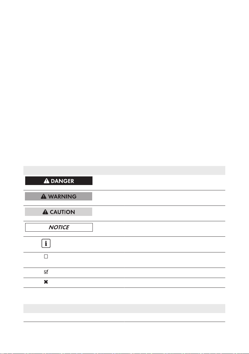
6. Release and remove all DC connectors. To do
this, insert a flat-blade screwdriver or an angled
screwdriver (blade width 3.5mm) into one of
the slide slots and pull the DC connectors out in
a downward direction. Do not pull on the cable.
2 Safety
Service Manual for Installers 5SB15-25-SG-en-10
Page 6
L
N
1
1
2
2 Safety
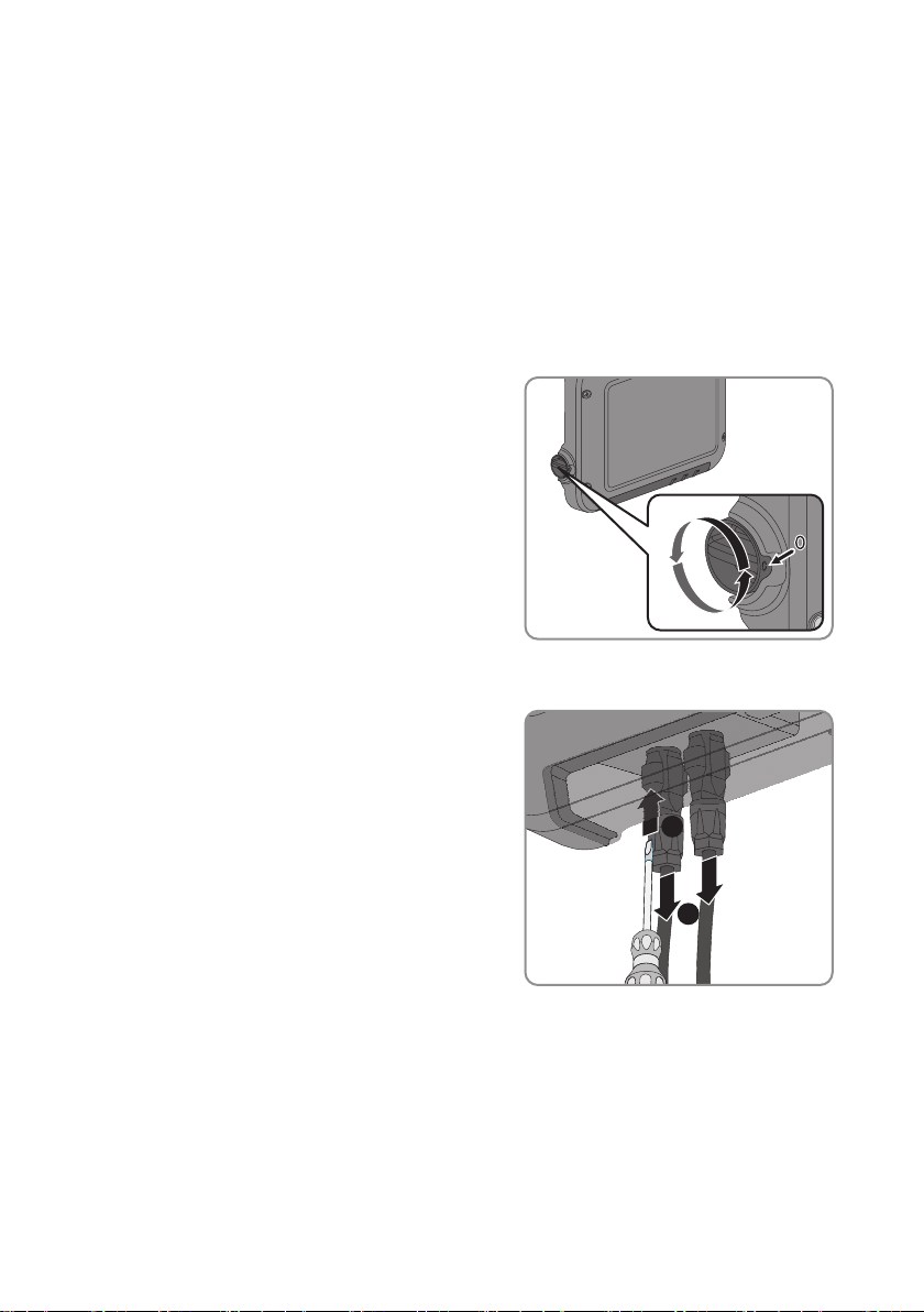
7. Ensure that no voltage is present at the DC
inputs on the inverter using a suitable measuring
device.
8. Loosen the swivel nuts.
9. Loosen the screws of the connection cap and
remove the connection cap.
SMA Solar Technology AG
10. Use a suitable measuring device to check that no voltage is present at the AC connector
between L and N and between L and the grounding conductor. To do so, insert the test probe
(maximum diameter: 2mm) into each round opening of the connecting terminal plate.
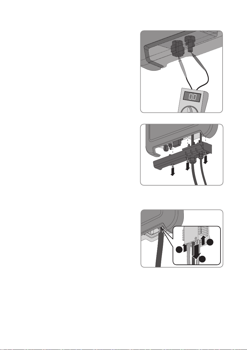
11. Release and disconnect the AC connector using
the sliders located on the side.
2.2 Safety Information
This section contains safety information that must be observed at all times when working on or with
the product.
To prevent personal injury and property damage and to ensure long-term operation of the product,
read this section carefully and observe all safety information at all times.
Service Manual for InstallersSB15-25-SG-en-106
Page 7
SMA Solar Technology AG
2 Safety
Danger to life due to high voltages of the PV array
When exposed to sunlight, the PV array generates dangerous DC voltage which is present in the
DC conductors and the live components of the inverter. Touching the DC conductors or the live
components can lead to lethal electric shocks. If you disconnect the DC connectors from the
inverter under load, an electric arc may occur leading to electric shock and burns.
• Do not touch non-insulated cable ends.
• Do not touch the DC conductors.
• Do not touch any live components of the inverter.
• Have the inverter mounted, installed and commissioned only by qualified persons with the
appropriate skills.
• If an error occurs, have it rectified by qualified persons only.
• Prior to performing any work on the inverter, disconnect it from all voltage sources as
described in this document (see Section2.1 "Disconnecting the Inverter from Voltage
Sources", page5).
Danger to life due to electric shock
Touching an ungrounded PV module or array frame can cause a lethal electric shock.
• Connect and ground the PV modules, array frame and electrically conductive surfaces so
that there is continuous conduction. Observe the applicable local regulations.
Damage to the inverter due to the use of cleaning agents
• If the inverter is dirty, clean the enclosure, the enclosure lid, the type label and the LEDs using
only clean water and a cloth.
Service Manual for Installers 7SB15-25-SG-en-10
Page 8
3 Calling Up the Inverter User Interface via Direct Connection
SMA Solar Technology AG
3 Calling Up the Inverter User Interface via Direct
Connection
You can call up the inverter user interface outside of a network via a direct connection between
computer, tablet PC or smartphone and the inverter. There are two methods available for this:
• Direct connection via WLAN
• Direct connection via Ethernet
Inverter SSID and IP address and necessary passwords
• Inverter SSID in WLAN: SMA[serial number] (e.g. SMA2130019815)
• Standard WLAN password: SMA12345 (usable for initial configuration prior to
completion of the first ten operating hours)
• Device-specific WLAN password: see WPA2-PSK on the inverter type label or the rear
side of the Quick Installation Guide included in delivery
• Standard inverter IP address for direct connection via WLAN outside of a local network:
192.168.100.1
• Standard inverter IP address for direct connection via Ethernet outside of a local network:
169.254.100.1
Direct connection via WLAN
Requirements:
☐ The inverter must be commissioned.
☐ A smartphone, tablet PC or computer with WLAN interface must be available.
☐ One of the following web browsers must be installed: Firefox (as of version 32), Internet
Explorer (as of version 10), Safari (as of version 6) or Google Chrome (as of version 32).
☐ The personal SMA Grid Guard code of the Installer must be available for the changing of
grid-relevant settings after completion of the first ten operating hours (see certificate
"Application for SMAGridGuard Code" at www.SMA-Solar.com).
File export via Safari web browser not possible
When using the Safari web browser, the exporting of files (e.g. saving the current inverter
configuration or exporting events) is not possible for technical reasons.
• Use a different supported web browser.
Procedure:
1. If your smartphone, tablet PC or computer has a WPS function:
• Tap twice on the lid of the inverter to activate the inverter WPS function.
☑ The inverter signalizes the open interface via the rapid flashing of the blue LED.
• Activate the WPS on your device.
☑ The connection with your device will be established automatically. Please note that
establishment of the connection to devices with Windows 7 or 8.1 can take up to 20
seconds.
2. If your smartphone, tablet PC or computer does not have a WPS function:
Service Manual for InstallersSB15-25-SG-en-108
Page 9
SMA Solar Technology AG
3 Calling Up the Inverter User Interface via Direct Connection
• Search for WLAN networks with your device.
• Select the inverter SSID SMA[serial number].
• Enter the inverter WLAN password. Within the first ten operating hours and prior to
closing the installation assistant for the first time, you can use the standard WLAN
password SMA12345. After this, you must use the device-specific inverter WLAN
password (WPA2-PSK), which is printed on the type label and the rear side of the Quick
Installation Guide included in delivery.
3. Enter 192.168.100.1 in the address line of the web browser and press the enter key.
☑ The login page of the user interface opens.
4. Log in as Installer or User. A new password must be assigned upon logging in for the first
time. To configure the inverter for the first time, login as an Installer.
5. Configure the inverter as desired.
Direct connection via Ethernet
Requirements:
☐ The inverter must be commissioned.
☐ A computer with an Ethernet interface must be available.
☐ One of the following web browsers must be installed: Firefox (as of version 32), Internet
Explorer (as of version 10), Safari (as of version 6) or Google Chrome (as of version 32).
☐ The inverter must be connected directly to a computer.
☐ The personal SMA Grid Guard code of the Installer must be available for the changing of
grid-relevant settings after completion of the first ten operating hours (see certificate
"Application for SMAGridGuard Code" at www.SMA-Solar.com).
File export via Safari web browser not possible
When using the Safari web browser, the exporting of files (e.g. saving the current inverter
configuration or exporting events) is not possible for technical reasons.
• Use a different supported web browser.
Procedure:
1. Enter 169.254.100.1 in the address line of the web browser and press the enter key.
☑ The login page of the user interface opens.
2. Log in as Installer or User. A new password must be assigned upon logging in for the first
time. The initial configuration of the inverter may only be performed by a qualified person. In
this case, login as an Installer.
3. Configure the inverter as desired.
Service Manual for Installers 9SB15-25-SG-en-10
Page 10

4 Event Messages
4 Event Messages
Event number Message, cause and corrective measures
101 to 103
202 to 205
Grid fault
The grid voltage or grid impedance at the connection point of the inverter is
too high. The inverter has disconnected from the utility grid.
Corrective measures:
• Check whether the grid voltage at the connection point of the inverter is
permanently in the permissible range.
If the grid voltage is outside the permissible range due to local grid
conditions, contact the grid operator. The grid operator must agree with
an adjustment of the voltage at the feed-in point or with a change of the
monitored operating limits.
If the grid voltage is permanently within the permissible range and this
message is still displayed, contact the Service (see Section11 "Contact",
page33).
Grid fault
The utility grid has been disconnected, the AC cable is damaged or the grid
voltage at the connection point of the inverter is too low. The inverter has disconnected from the utility grid.
Corrective measures:
• Make sure that the circuit breaker is switched on.
• Ensure that the AC cable is not damaged and that it is connected
correctly.
• Ensure that the country data set has been configured correctly.
• Check whether the grid voltage at the connection point of the inverter is
permanently in the permissible range.
If the grid voltage is outside the permissible range due to local grid
conditions, contact the grid operator. The grid operator must agree with
an adjustment of the voltage at the feed-in point or with a change of the
monitored operating limits.
If the grid voltage is permanently within the permissible range and this
message is still displayed, contact the Service (see Section11 "Contact",
page33).
.
SMA Solar Technology AG
Service Manual for InstallersSB15-25-SG-en-1010
Page 11
SMA Solar Technology AG
Event number Message, cause and corrective measures
301
Grid fault
The ten-minute average value of the grid voltage is no longer within the permissible range. The grid voltage or grid impedance at the connection point is
too high. The inverter disconnects from the utility grid to maintain power quality.
Corrective measures:
• During the feed-in operation, check whether the grid voltage at the
connection point of the inverter is permanently in the permissible range.
If the grid voltage is outside the permissible range due to local grid
conditions, contact the grid operator. The grid operator must agree with
an adjustment of the voltage at the feed-in point or with a change of the
monitored operating limits.
If the grid voltage is permanently within the permissible range and this
message is still displayed, contact the Service (see Section11 "Contact",
page33).
302
Temperature AC voltage
The inverter has reduced its power due to a too-high grid voltage to ensure
grid stability.
Corrective measures:
• If possible, check the grid voltage and observe how often fluctuations
occur. If fluctuations occur frequently and this message is displayed often,
contact the grid operator and request approval to change the operating
parameters of the inverter. If the grid operator gives his approval, discuss
any changes to the operating parameters with Service (see Section11
"Contact", page33).
401to 404
Grid fault
The inverter has disconnected from the utility grid. A stand-alone grid or a very
large change in the power frequency was detected.
Corrective measures:
• Check the grid connection for significant short-term frequency fluctuations.
4 Event Messages
Service Manual for Installers 11SB15-25-SG-en-10
Page 12

4 Event Messages
Event number Message, cause and corrective measures
501
Grid fault
The power frequency is not within the permissible range. The inverter has disconnected from the utility grid.
Corrective measures:
• If possible, check the power frequency and observe how often
fluctuations occur.
If fluctuations occur frequently and this message is displayed often,
contact the grid operator and request approval to change the operating
parameters of the inverter.
If the grid operator gives his approval, discuss any changes to the
operating parameters with Service (see Section11 "Contact", page33).
507
Temperature AC frequency
The inverter has reduced its power due to a too-high power frequency to ensure grid stability.
Corrective measures:
• If possible, check the power frequency and observe how often
fluctuations occur. If fluctuations occur frequently and this message is
displayed often, contact the grid operator and request approval to
change the operating parameters of the inverter. If the grid operator
gives his approval, discuss any changes to the operating parameters with
Service (see Section11 "Contact", page33).
601
Grid fault
The inverter has detected an excessively high proportion of direct current in
the grid current.
Corrective measures:
• Check the grid connection for direct current.
• If this message is displayed frequently, contact the grid operator and
check whether the monitoring threshold on the inverter can be raised.
701
Frq. not permitted > Check parameter
The power frequency is not within the permissible range. The inverter has disconnected from the utility grid.
Corrective measures:
• If possible, check the power frequency and observe how often
fluctuations occur.
If fluctuations occur frequently and this message is displayed often,
contact the grid operator and request approval to change the operating
parameters of the inverter.
If the grid operator gives his approval, discuss any changes to the
operating parameters with Service (see Section11 "Contact", page33).
SMA Solar Technology AG
Service Manual for InstallersSB15-25-SG-en-1012
Page 13

SMA Solar Technology AG
Event number Message, cause and corrective measures
801
Waiting for grid voltage > Grid failure > Check AC circuit breaker
The AC cable is not correctly connected or the country data set is not correctly
configured.
Corrective measures:
• Make sure that the circuit breaker is switched on.
• Ensure that the AC cable is not damaged and that it is connected
correctly.
• Ensure that the country data set has been configured correctly.
• Check whether the grid voltage at the connection point of the inverter is
permanently in the permissible range.
If the grid voltage is outside the permissible range due to local grid
conditions, contact the grid operator. The grid operator must agree with
an adjustment of the voltage at the feed-in point or with a change of the
monitored operating limits.
If the grid voltage is permanently within the permissible range and this
message is still displayed, contact the Service (see Section11 "Contact",
page33).
.
901
PE conn. missing > Check connection
The grounding conductor is not correctly connected.
Corrective measures:
• Ensure that PE is correctly connected (see operating manual of the
inverter).
1001
L/N swapped > Check connection
The connection of L and N is swapped.
Corrective measures:
• Ensure that L and N are correctly connected (see operating manual of
the inverter).
1101
Installation fault > Check connection
A second line conductor is connected to N.
Corrective measures:
• Connect the neutral conductor to N.
4 Event Messages
Service Manual for Installers 13SB15-25-SG-en-10
Page 14

4 Event Messages
Event number Message, cause and corrective measures
1302
Waiting for grid voltage > Installation failure grid connection > Check
grid and fuses
L or N not connected.
Corrective measures:
• Ensure that L and N are connected.
• Make sure that the circuit breaker is switched on.
• Ensure that the AC cable is not damaged and that it is connected
correctly.
1501
Reconnection fault grid
The changed country data set or the value of a parameter you have set does
not correspond to the local requirements. The inverter cannot connect to the
utility grid.
Corrective measures:
• Ensure that the country data set has been configured correctly. To do this,
select the parameter Set country standard and check the value.
3301 to 3303
Unstable operation
There is not enough power at the DC input of the inverter for stable operation.
The inverter cannot connect to the utility grid.
Corrective measures:
• Ensure that the PV array is designed correctly.
• Ensure that the PV array is not covered by snow or otherwise shaded.
• Ensure that the PV array is free of errors.
3401
DC overvoltage > Disconnect generator
Overvoltage at the DC input. This can destroy the inverter.
This message is signalized additionally by rapid flashing of the LEDs.
Corrective measures:
• Immediately disconnect the inverter from all voltage sources (see
Section2.1, page5).
• Check whether the DC voltage is below the maximum input voltage of
the inverter. If the DC voltage is below the maximum input voltage of the
inverter, reconnect the DC connectors to the inverter.
• If the DC voltage exceeds the maximum input voltage of the inverter,
ensure that the PV array has been correctly rated or contact the installer
of the PV array.
• If this message is repeated frequently, contact the Service (see
Section11 "Contact", page33).
SMA Solar Technology AG
Service Manual for InstallersSB15-25-SG-en-1014
Page 15

SMA Solar Technology AG
Event number Message, cause and corrective measures
3501
Insulation failure > Check generator
The inverter has detected a ground fault in the PV array.
Corrective measures:
• Check the PV system for ground faults (see Section6, page26).
3601
High discharge curr. > Check generator
The leakage current of the inverter and the PV array is too high. There is a
ground fault, a residual current or a malfunction.
The inverter interrupts feed-in operation immediately after exceeding a threshold. When the fault is eliminated, the inverter automatically reconnects to the
utility grid.
Corrective measures:
• Check the PV system for ground faults (see Section6, page26).
3701
Resid.curr.too.high > Check generator
The inverter has detected a residual current due to temporary grounding of the
PV array.
Corrective measures:
• Check the PV system for ground faults (see Section6, page26).
3801
DC overcurrent > Check generator
Overcurrent at the DC input. The inverter briefly interrupts feed-in operation.
Corrective measures:
• If this message is displayed frequently, ensure that the PV array has been
correctly rated and wired.
3901 to 3902
Waiting for DC start conditions > Start cond. not met
The feed-in conditions for the utility grid are not yet fulfilled.
Corrective measures:
• Ensure that the PV array is not covered by snow or otherwise shaded.
• Wait for higher irradiation.
• If this message is displayed frequently in the morning, increase the
voltage limit for starting grid feed-in. Change the parameter Critical
voltage to start feed-in.
• If this message is displayed frequently with medium irradiation, ensure
that the PV array is correctly rated.
6001 to 6438
Self diagnosis > Interference device
The cause must be determined by the SMAServiceLine.
Corrective measures:
• Contact the Service (see Section11 "Contact", page33).
4 Event Messages
Service Manual for Installers 15SB15-25-SG-en-10
Page 16

4 Event Messages
Event number Message, cause and corrective measures
6501 to 6509
Self-diagnosis > Overtemperature
The inverter has switched off due to excessive temperature.
Corrective measures:
• Clean the cooling fins on the rear of the enclosure and the air ducts on
the top using a soft brush.
• Ensure that the inverter has sufficient ventilation.
• Ensure that the ambient temperature 40°C has not been exceeded.
• Ensure that the inverter is not exposed to direct solar irradiation.
6512
Minimum operating temperature not reached
The inverter will only recommence feeding into the utility grid once the temperature has reached at least -25°C.
6603to 6604
Self-diagnosis > Overload
The cause must be determined by the Service.
Corrective measures:
• Contact the Service (see Section11 "Contact", page33).
6701to 6702
Communication disturbed
Error in the communication processor, the inverter continues feeding in, however. The cause must be determined by the Service.
Corrective measures:
• If this message is displayed frequently, contact the Service (see
Section11 "Contact", page33).
7001to 7002
Sensor fault
A temperature sensor in the inverter is defective and the inverter interrupts the
feed-in operation. The cause must be determined by the Service.
Corrective measures:
• Contact the Service (see Section11 "Contact", page33).
7201to 7202
Data stor. not poss.
Internal error. The inverter continues to feed into the utility grid.
Corrective measures:
• Contact the Service (see Section11 "Contact", page33).
7303
Update main CPU failed
The cause must be determined by the Service.
Corrective measures:
• Contact the Service (see Section11 "Contact", page33).
7320
The device with serial number [x] was successfully updated to
firmware version [x].
The firmware update was completed successfully.
SMA Solar Technology AG
Service Manual for InstallersSB15-25-SG-en-1016
Page 17

SMA Solar Technology AG
Event number Message, cause and corrective measures
7329
Condition test successful
The testing of the update conditions was successful. The firmware update
package is suitable for this inverter.
7330
Condition test failed
The testing of the update conditions was not successful. The firmware update
package is not suitable for this inverter.
Corrective measures:
• Retry update.
• Ensure that the selected update file is suitable for this inverter.
• If this message is displayed again, contact the Service (see Section11
"Contact", page33).
7331
Update transport started
Update file is being copied.
7332
Update transport successful
Update file was copied successfully to the inverter's internal memory.
7333
Update transport failed
Update file could not be copied to the inverter's internal memory. In the event
of connection with the inverter via WLAN, a poor connection quality can be
the cause.
Corrective measures:
• Retry update.
• For WLAN connection: Improve the WLAN connection quality (e.g. via
WLAN repeater) or establish connection with the inverter via Ethernet.
• If this message is displayed again, contact the Service (see Section11
"Contact", page33).
7341
Update Bootloader
The inverter is performing a bootloader update.
7342
Update Bootloader failed
The bootloader update failed.
Corrective measures:
• Retry update.
• If this message is displayed again, contact the Service (see Section11
"Contact", page33).
4 Event Messages
Service Manual for Installers 17SB15-25-SG-en-10
Page 18

4 Event Messages
Event number Message, cause and corrective measures
7347
Incompatible file
The configuration file is not suitable for this inverter.
Corrective measures:
• Ensure that the selected configuration file is suitable for this inverter.
• Retry import.
7348
Incorrect file format
The configuration file is not of the required format or is damaged.
Corrective measures:
• Ensure that the selected configuration file is of the required format and is
not damaged.
• Retry import.
7349
Incorrect login rights for configuration file
The user group logged in does not have the user rights necessary to be able
to import a configuration.
Corrective measures:
• Log in as Installer.
• Import configuration file again.
7350
Transfer of a configuration file has started
The configuration file is being transferred.
7351
Update WLAN
The inverter is updating the WLAN module.
7352
Update of WLAN not successful
The update of the WLAN module failed.
Corrective measures:
• Retry update.
• If this message is displayed again, contact the Service (see Section11
"Contact", page33).
7353
Update time zone database
The inverter is updating the time zone database.
7354
Update of time zone database not successful
The update of the time zone database failed.
Corrective measures:
• Retry update.
• If this message is displayed again, contact the Service (see Section11
"Contact", page33).
SMA Solar Technology AG
Service Manual for InstallersSB15-25-SG-en-1018
Page 19

SMA Solar Technology AG
Event number Message, cause and corrective measures
7355
Update WebUI
The inverter is updating the inverter user interface.
7356
Update of the WebUI not successful
The update of the inverter user interface failed.
Corrective measures:
• Retry update.
• If this message is displayed again, contact the Service (see Section11
"Contact", page33).
7619
Communication fault with meter unit > Check communication to meter
The inverter is not receiving any data from the energy meter.
Corrective measures:
• Ensure that the energy meter is correctly integrated into the same network
as the inverter (see energy meter manual).
• For WLAN connection: Improve the WLAN connection quality (e.g. via
WLAN repeater) or connect the inverter with the DHCP server (router) via
Ethernet.
7701to 7703
Self diagnosis > Interference device
The cause must be determined by the Service.
Corrective measures:
• Contact the Service (see Section11 "Contact", page33).
8003
Temperature derating
The inverter has reduced its power output for more than ten minutes due to excessive temperature.
Corrective measures:
• Clean the cooling fins on the rear of the enclosure and the air ducts on
the top using a soft brush.
• Ensure that the inverter has sufficient ventilation.
• Ensure that the ambient temperature 40°C has not been exceeded.
• Ensure that the inverter is not exposed to direct solar irradiation.
4 Event Messages
Service Manual for Installers 19SB15-25-SG-en-10
Page 20

4 Event Messages
Event number Message, cause and corrective measures
8708
Timeout in communication for active power limitation
Communication to the system control absent. Depending on the fall-back setting, either the last received values will be retained or the active power will be
limited to the set percentage value of the inverter nominal power.
Corrective measures:
• Ensure that the connection to the system manager (e.g.
SunnyHomeManager) is intact and that no cables are damaged or that
no plugs have been pulled.
SMA Solar Technology AG
8709
8710
9002
9003
Timeout in communication for reactive power spec.
Communication to the system control absent. Depending on the fall-back setting, either the last received values will be retained or the reactive power will
be set to the set value.
Corrective measures:
• Ensure that the connection to the system manager (e.g.
SunnyHomeManager) is intact and that no cables are damaged or that
no plugs have been pulled.
Timeout in communication for cos-Phi spec.
Communication to the system control absent. Depending on the fall-back setting, either the last received values will be retained or the displacement power
factor will be set to the set value.
Corrective measures:
• Ensure that the connection to the system manager (e.g.
SunnyHomeManager) is intact and that no cables are damaged or that
no plugs have been pulled.
SMA Grid Guard code invalid
The SMAGridGuard code entered is incorrect. The operating parameters are
still protected and cannot be changed.
Corrective measures:
• Enter the correct SMAGridGuard code.
Grid parameter locked
Changes to the grid parameters are now blocked. In order to be able to make
changes to the grid parameters, from now on you must log in using the SMA
Grid Guard code.
Service Manual for InstallersSB15-25-SG-en-1020
Page 21

SMA Solar Technology AG
Event number Message, cause and corrective measures
9005
Changing of grid parameters not possible > Ensure DC supply.
This error can have the following causes:
• The parameters to be changed are protected.
• The DC voltage at the DC input is not sufficient to run the main CPU.
Corrective measures:
• Enter the SMA Grid Guard code.
• Ensure that at least the DC start voltage is available (green LED is
flashing, pulsing or glowing).
9007
Abort self-test
The self-test (Italy only) was terminated.
Corrective measures:
• Ensure that the AC connection is correct.
• Restart the self-test (see the inverter operating manual at www.SMASolar.com).
10110
Time synchronization failed [x]
No time information could be called up from the set NTP server.
Corrective measures:
• Ensure that the NTP server was configured correctly.
• Ensure that the inverter is integrated into a local network with Internet
connection.
10248
[Interface]: network busy
The network is busy. Data exchange between the devices is not at an optimum
and is greatly delayed.
Corrective measures:
• Increase the query intervals.
• If necessary, reduce the number of devices in the network.
10249
[Interface]: network overloaded
The network is overloaded. There is no data exchange between the devices.
Corrective measures:
• Reduce the number of devices in the network.
• If necessary, increase the data query intervals.
4 Event Messages
Service Manual for Installers 21SB15-25-SG-en-10
Page 22

4 Event Messages
Event number Message, cause and corrective measures
10250
[Interface]: package error rate [ok / high]
The package error rate has changed. If the package error rate is high, the network is overloaded or the connection to the network switch or DHCP server
(router) is disturbed.
Corrective measures if the package error rate is high:
• Ensure that with an Ethernet connection, the network cable and the
network connector are not damaged and that the network connector is
correctly plugged.
• If necessary, increase the data query intervals.
• If necessary, reduce the number of devices in the network.
10251
[Interface]: communication status goes to [OK / Warning / Error /
Not connected]
The communication status to the network switch or DHCP server (router) has
changed. An additional error message may be displayed.
10252
[Interface]: communication disrupted
There is no valid signal on the network line.
Corrective measures:
• Ensure that with an Ethernet connection, the network cable and the
network connector are not damaged and that the network connector is
correctly plugged.
• Ensure that the DHCP server (router) and any network switches are
signalizing correct operation.
10253
[Interface]: connection speed goes to [100Mbit / 10Mbit]
The data transfer rate has changed. The cause for the status [10 Mbit] can be
a defective plug, a defective cable or the pulling or plugging of the network
connector.
Corrective measures if the status is [10 Mbit]:
• Ensure that with an Ethernet connection, the network cable and the
network connector are not damaged and that the network connector is
correctly plugged.
• Ensure that the DHCP server (router) and any network switches are
signalizing correct operation.
SMA Solar Technology AG
Service Manual for InstallersSB15-25-SG-en-1022
Page 23

SMA Solar Technology AG
Event number Message, cause and corrective measures
10254
[Interface]: duplex mode goes to [Full / Half]
The duplex mode (data transfer mode) has changed. The cause for the status
[Half] can be a defective plug, a defective cable or the pulling or plugging of
the network connector.
Corrective measures if the status is [Half]:
• Ensure that with an Ethernet connection, the network cable and the
network connector are not damaged and that the network connector is
correctly plugged.
• Ensure that the DHCP server (router) and any network switches are
signalizing correct operation.
10255
[Interface]: Network load OK
The network load has returned to a normal range after being busy.
10282
[User group]-Login via [protocol] locked
After several incorrect login attempts, login has been blocked for a limited
time. In this case, the User login will be blocked for 15minutes, the
GridGuard login for 12hours.
Corrective measures:
• Wait until the given time has expired and then retry login.
10283
WLAN module faulty
The WLAN module integrated in the inverter is defective.
Corrective measures:
• Contact the Service (see Section11 "Contact", page33).
10284
No WLAN connection possible
The inverter does not currently have a WLAN connection to the selected network.
Corrective measures:
• Ensure that the SSID, the WLAN password and the encryption method
have been entered correctly. The encryption method is specified by your
WLAN router or WLAN Access Point and can be changed there.
• Ensure that the WLAN router or WLAN Access Point is in range and is
signalizing correct operation.
• If this message is displayed often, improve the WLAN connection by
using a WLAN repeater.
10285
WLAN connection established
Connection to the selected WLAN network has been established.
4 Event Messages
Service Manual for Installers 23SB15-25-SG-en-10
Page 24

4 Event Messages
Event number Message, cause and corrective measures
10286
WLAN connection lost
The inverter has lost WLAN connection to the selected network.
Corrective measures:
• Ensure that the WLAN router or WLAN Access Point is still active.
• Ensure that the WLAN router or WLAN Access Point is in range and is
signalizing correct operation.
• If this message is displayed often, improve the WLAN connection by
using a WLAN repeater.
27301
Update communication
The inverter is updating the communication component.
27302
Update main CPU
The inverter is updating the inverter component.
27312
Update completed
The inverter has successfully completed the update.
29004
Grid parameter unchanged
Changing the grid parameters is not possible.
20901
Inst. code valid
The entered GridGuard code is valid. Protected parameters have now been
unlocked and you can adjust the parameters. The parameters will be automatically locked again after ten feed-in hours.
20906
Self-test
The self-test is in progress.
SMA Solar Technology AG
Service Manual for InstallersSB15-25-SG-en-1024
Page 25

SMA Solar Technology AG
5 Cleaning the Inverter
5 Cleaning the Inverter
Damage to the inverter due to the use of cleaning agents
• If the inverter is dirty, clean the enclosure, the enclosure lid, the type label and the LEDs using
only clean water and a cloth.
• Ensure that the inverter is free of dust, foliage and other dirt.
Service Manual for Installers 25SB15-25-SG-en-10
Page 26

6 Checking the PV System for Ground Faults
SMA Solar Technology AG
6 Checking the PV System for Ground Faults
If the inverter displays the event numbers 3501, 3601 or 3701, there could be a ground fault. The
electrical insulation from the PV system to ground is defective or insufficient.
Danger to life due to electric shock
In the event of a ground fault, high voltages can be present.
• Touch the cables of the PV array on the insulation only.
• Do not touch any parts of the substructure or frame of the PV array.
• Do not connect PV strings with ground faults to the inverter.
Destruction of the measuring device due to overvoltage
• Only use measuring devices with a DC input voltage range of 1,000 V or higher.
Procedure:
In order to check the PV system for ground faults, perform the following actions in the prescribed
order. The exact procedure is described in the following sections.
• Check the PV system for ground faults by measuring the voltage.
• If the voltage measurement was not successful, check the PV system via insulation resistance
measurement for ground faults.
Test by Measuring the Voltage
Proceed as follows to check each string in the PV system for ground faults.
Procedure:
1.
Danger to life due to high voltages
• Disconnect the inverter from all voltage sources (see Section2.1, page5).
2. Measure the voltages:
• Measure the voltage between the positive terminal and the ground potential (PE).
• Measure the voltage between the negative terminal and the ground potential (PE).
• Measure the voltage between the positive and negative terminals.
If the following results are present at the same time, there is a ground fault in the PV
system:
☑ All measured voltages are stable.
☑ The sum of the two voltages to ground potential is approximately equal to the
voltage between the positive and negative terminals.
• If a ground fault is present, determine the location of the ground fault via the ratio of the
two measured voltages and eliminate the ground fault.
Service Manual for InstallersSB15-25-SG-en-1026
Page 27

SMA Solar Technology AG
6 Checking the PV System for Ground Faults
Example: Location of the ground fault
The example shows a ground fault between the second and third PV module.
3. If a definite ground fault cannot be measured and the message is still displayed, measure the
insulation resistance.
4. Reconnect the strings without ground faults to the inverter and recommission the inverter (see
Section8, page30).
Test by Measuring the Insulation Resistance
If the voltage measurement does not provide sufficient evidence of a ground fault, the insulation
resistance measurement can provide more exact results.
Figure 1: Schematic diagram of the measurement
Service Manual for Installers 27SB15-25-SG-en-10
Page 28

total
6 Checking the PV System for Ground Faults
SMA Solar Technology AG
Calculating the insulation resistance
The expected total resistance of the PV system or of an individual string can be calculated
using the following formula:
The exact insulation resistance of a PV module can be obtained from the module manufacturer
or the datasheet.
For the resistance of a PV module an average value can be assumed: for thin-film PV modules
approximately 40MOhm and for polycrystalline and monocrystalline PV modules
approximately50MOhm per PV module (for further information on calculating the insulation
resistance see the Technical Information "Insulation Resistance (Riso) of Non-Galvanically
Isolated PV Systems" at www.SMA-Solar.com).
Required devices:
☐ Suitable device for safe disconnection and short-circuiting
☐ Measuring device for insulation resistance
Device required for safe disconnection and short-circuiting of the PV array
The insulation resistance can only be measured with a suitable device for safe disconnection
and short-circuiting of the PV array. If no suitable device is available, the insulation
measurement must not be carried out.
Procedure:
1. Calculate the expected insulation resistance per string.
2.
Danger to life due to high voltages
• Disconnect the inverter from all voltage sources (see Section2.1, page5).
3. Install the short circuit device.
4. Connect the measuring device for insulation resistance.
5. Short-circuit the first string.
6. Set the test voltage. The test voltage should be as close as possible to the maximum system
voltage of the PV modules but must not exceed it (see datasheet of the PV modules).
7. Measure the insulation resistance.
8. Eliminate the short circuit.
9. Measure the remaining strings in the same manner.
☑ If the insulation resistance of a string deviates considerably from the theoretically
calculated value, there is a ground fault present in that string.
10. Reconnect to the inverter only those strings from which the ground fault has been eliminated.
11. Reconnect all other strings to the inverter.
12. Recommission the inverter (see Section8, page30).
13. If the inverter still displays an insulation error, contact the Service (see Section11 "Contact",
page33). The PV modules might not be suitable for the inverter in the present quantity.
Service Manual for InstallersSB15-25-SG-en-1028
Page 29

SMA Solar Technology AG
7 Opening the Inverter
7 Opening the Inverter
If you have to open the inverter enclosure lid for repairs or replacement, proceed as described in
the following.
Damage to the seal of the enclosure lid in sub-zero conditions
If you open the enclosure lid in sub-zero conditions, the sealing of the enclosure lid can be
damaged. This can lead to moisture entering the inverter.
• Do not open the inverter at ambient temperatures lower than -5°C.
• If a layer of ice has formed on the seal of the enclosure lid in sub-zero conditions, remove it
prior to opening the inverter (e.g. by melting the ice with warm air). Observe the applicable
safety regulations.
Procedure:
1.
Danger to life due to high voltages
• Disconnect the inverter from all voltage sources (see Section2.1, page5).
• Wait five minutes until the capacitors have discharged.
2. To prevent water or dust entering the interior of the inverter, clean and dry the lid prior to
removal.
3. Unscrew all four enclosure lid screws using a Torx screwdriver (TX25) and store safely.
4. Carefully remove the enclosure lid.
5.
Damage to the inverter due to electrostatic discharge
The internal components of the inverter can be irreparably damaged by electrostatic
discharge.
• Ground yourself before touching any component.
6. Perform the repair or replacement.
7. Replace the enclosure lid with the four screws onto the enclosure and hold in place.
8. Tighten all four screws using a Torx screwdriver (TX25) crosswise (torque: 6Nm).
9. Recommission the inverter (see Section8, page30).
Service Manual for Installers 29SB15-25-SG-en-10
Page 30

1
2
3
8 Recommissioning the Inverter
SMA Solar Technology AG
8 Recommissioning the Inverter
Requirements:
☐ The inverter must be correctly mounted.
☐ The circuit breaker must be correctly rated.
☐ All cables must be correctly connected.
Procedure:
1. Attach the connection cap to the inverter using
the three screws and a Torx screwdriver (TX20)
(torque: 3.5Nm).
2. Tighten the swivel nuts of the AC cable gland and network connection hand-tight.
3. Set the DC load-break switch of the inverter to position 1.
4. Switch on the circuit breaker.
☑ The green LED flashes slowly on and off or glows permanently. Feed-in operation begins.
✖ Green LED is flashing?
The DC input voltage is still too low.
• Once the DC input voltage is sufficiently high, feed-in operation begins.
✖ The red LED is glowing?
There is probably an error.
• Call up the inverter user interface (see Section3 "Calling Up the Inverter User
Interface via Direct Connection", page8).
• Call up the menu Events and identify the error via the event ID.
• Rectify the error (see Section4 "Event Messages", page10).
5. If required, configure the inverter via the user interface.
Service Manual for InstallersSB15-25-SG-en-1030
Page 31

SMA Solar Technology AG
9 Decommissioning the Inverter
9 Decommissioning the Inverter
To decommission the inverter completely upon completion of its service life, proceed as described
in this Section.
Risk of injury when lifting the inverter, or if it is dropped
The inverter weighs 9kg. There is risk of injury if the inverter is lifted incorrectly or dropped while
being transported or when attaching it to or removing it from the wall mounting bracket.
• Transport and lift the inverter carefully.
1.
Danger to life due to high voltages
• Disconnect the inverter from all voltage sources (see Section2.1, page5).
2.
Risk of burns due to hot enclosure parts
• Wait 30 minutes for the enclosure to cool down.
3. If an additional grounding or an equipotential
bonding is connected, remove the cylindrical
screw using a Torx screwdriver (TX25) and
remove the grounding cable.
4. Remove the inverter from the wall.
5. If the inverter is to be stored or shipped, pack the inverter. Use the original packaging or
packaging that is suitable for the weight and dimensions of the inverter.
6. Dispose of the inverter in accordance with the locally applicable disposal regulations for
electronic waste.
Service Manual for Installers 31SB15-25-SG-en-10
Page 32

10 Spare Parts
SMA Solar Technology AG
10 Spare Parts
You will find the spare parts for your product in the following overview. If required, these can be
ordered from SMA Solar Technology AG or your distributor.
Designation Brief description SMA order
number
Enclosure lid Enclosure lid red 90-157500.02
Connection cap Connection cap for covering the connection
area
accessory kit Accessory kit with DC connectors, grounding ter-
minal for additional grounding and AC connector
Switching lever of the DC
load-break switch
Switching lever of the DC load-break switch as
spare part
90-133100.06
85-101600.01
90-206200.01
Service Manual for InstallersSB15-25-SG-en-1032
Page 33

SMA Solar Technology AG
11 Contact
11 Contact
If you have technical problems with our products, please contact the SMAServiceLine. We need
the following information in order to provide you with the necessary assistance:
Australia SMA Australia Pty Ltd.
Sydney
Toll free for Australia:
1800SMAAUS
(1800762287)
International: +61294914200
Argentina
Brasil
Chile
Perú
Danmark
Deutschland
Österreich
Schweiz
España
Portugal
SMA South America SPA
Santiago
+562 2820 2101
SMA Solar Technology AG
Niestetal
SMA Online Service Center:
www.SMA.de/Service
Sunny Boy, Sunny Mini Central,
SunnyTripower:
+495619522‑1499
Monitoring Systems (Kommunikationsprodukte):
+495619522‑2499
Fuel Save Controller (PV-DieselHybridsysteme):
+495619522-3199
Sunny Island, Sunny Backup, Hydro Boy: +495619522-399
Sunny Central:
+495619522-299
SMA Ibérica Tecnología Solar,
S.L.U.
Barcelona
+34935635099
Belgien
Belgique
België
Luxemburg
Luxembourg
Nederland
Česko
Magyarország
Polska
România
Slovensko
France SMA France S.A.S.
India SMA Solar India Pvt. Ltd.
SMA Benelux BVBA/SPRL
Mechelen
+3215286 730
SMA Central & Eastern
Europes.r.o.
Praha
+420235010417
Lyon
Sunny Boy, Sunny Mini Central,
Sunny Tripower:
+33472090440
Monitoring Systems:
+33472090441
Sunny Island :
+33472090442
Sunny Central :
+33472090443
Mumbai
+912261713888
Service Manual for Installers 33SB15-25-SG-en-10
Page 34

5%6!78%
9:;*<+%,='3)>+%
/01,234
9:;
11 Contact
SMA Solar Technology AG
South Africa SMA Solar Technology South
Africa Pty Ltd.
Centurion (Pretoria)
08600SUNNY
(0860078669)
International:
+27(12)6223000
Italia SMA Italia S.r.l.
Milano
+39028934-7299
SMA Solar (Thailand) Co., Ltd.
+6626706999
SMA Middle East LLC
+9712234-6177
Ελλάδα
Κύπρος
Kıbrıs
България
United
Kingdom
대한민국 SMA Technology Korea Co.,
Other countries International SMA Service Line
SMA Hellas AE
Αθήνα
8012229222
International:
+302122229222
SMA Solar UK Ltd.
Milton Keynes
+441908304899
Ltd.
서울
+82-2-520-2666
Niestetal
Toll free worldwide:
00800SMASERVICE
(+8007627378423)
Service Manual for InstallersSB15-25-SG-en-1034
Page 35

Page 36

SMA Solar Technology
www.SMA-Solar.com
 Loading...